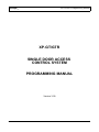
1
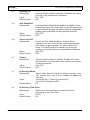
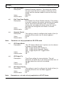
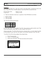
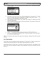
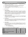
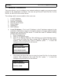
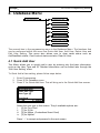
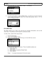
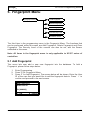
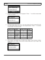
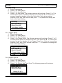
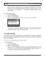
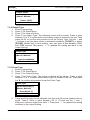
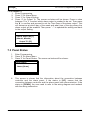
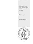
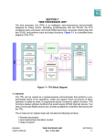
MicroEngine ®
XP-GT/GTR Programming Manual
XP-GT/GTR
SINGLE DOOR ACCESS
CONTROL SYSTEM
PROGRAMMING MANUAL
Version 3.00
V3.00
1
MicroEngine ®
XP-GT/GTR Programming Manual
MicroEngine XP-GT/GTR Controller Programming Manual
Revision History
Version Date
Remarks
1.00
1/1/2007
First Release of Manual
2.00
8/3/2008
Updated arrangements and drawings
2.10
17/7/2008
Updated drawings and included the XP-GTR series to the manual. Also
added a page to indicate scope of manual.
3.00
20/7/2009
Updated System Menu, added Alarm Menu and wiring diagram for XPGTR to MIO44. Also added the connection for XP-GT/GTR using
sounder and fire release feature.
V3.00
2
MicroEngine ®
XP-GT/GTR Programming Manual
Scope:
This manual covers the following products
1.
2.
3.
4.
5.
6.
7.
8.
V3.00
XP-GT1200
XP-GT3200
XP-GT1200L
XP-GT3200L
XP-GTR1200
XP-GTR3000
XP-GTR1200L
XP-GTR3000L
3
MicroEngine ®
XP-GT/GTR Programming Manual
Table of Contents
1.XP-GT/GTR Single Door Access Control System........................................................6
1.1Powering Up..................................................................................................................................6
1.2Idle Mode.......................................................................................................................................7
1.3Token Operation ..........................................................................................................................7
1.4Token+PIN Operation ..................................................................................................................8
1.5Token+Fingerprint Operation .......................................................................................................8
1.6Token+PIN+Fingerprint Operation ...............................................................................................8
1.7Symbols........................................................................................................................................9
2.Programming Environment........................................................................................10
2.1Programming Menu Layout........................................................................................................10
2.2Keypad Button Functions Keypad Button Functions..................................................................10
2.3Entering Programming Mode......................................................................................................10
3.System Menu..............................................................................................................12
3.1Set Date and Time......................................................................................................................12
3.2Door Parameter..........................................................................................................................13
3.3Time Set .....................................................................................................................................18
3.4Time Zone ..................................................................................................................................20
3.5Holiday Setting............................................................................................................................23
3.6General Parameter.....................................................................................................................24
3.7Network Parameters...................................................................................................................26
3.8Sounder Setting..........................................................................................................................28
3.9O/P Trigger Events.....................................................................................................................29
4.Database Menu..........................................................................................................30
4.1Quick Add User...........................................................................................................................30
4.2Add User.....................................................................................................................................31
4.3Delete User.................................................................................................................................33
4.4Edit User Settings.......................................................................................................................34
4.5Clear Anti PassBack...................................................................................................................35
4.6Clear Card LockOut....................................................................................................................36
4.7Clear All User..............................................................................................................................36
V3.00
4
MicroEngine ®
XP-GT/GTR Programming Manual
5.Fingerprint Menu........................................................................................................38
5.1Add Fingerprint............................................................................................................................38
5.2Delete Fingerprint.......................................................................................................................40
5.3Clear Fingerprint.........................................................................................................................40
5.4Template Enrolled.......................................................................................................................41
5.5Set Security Level.......................................................................................................................41
6.Maintenance Menu.....................................................................................................43
6.1Master PIN..................................................................................................................................43
6.2Clear Transaction........................................................................................................................44
6.3Test Watchdog............................................................................................................................44
6.4Version........................................................................................................................................45
6.5Information..................................................................................................................................45
7.Alarm Menu................................................................................................................46
7.1Input Setting................................................................................................................................46
7.2Output Setting.............................................................................................................................48
7.3Panel Status................................................................................................................................50
8.Exit Programming Menu.............................................................................................51
Appendix 1 – General Wiring for XP-GT using MAS-RBT..............................................................52
Appendix 2 – General Wiring for XP-GTR using MAS-RBU...........................................................53
Appendix 3 – General Wiring for two XP-GT using MAS-RBT........................................................54
Appendix 4 - Connection for XP-GT using sounder feature............................................................55
Appendix 5 - Connection for XP-GTR using sounder feature.........................................................56
Appendix 6 - Connection for XP-GT and XP-GTR using fire release feature.................................57
Appendix 7 - Connection for XP-GTR to MIO44..............................................................................58
V3.00
5
MicroEngine ®
XP-GT/GTR Programming Manual
1. XP-GT/GTR Single Door Access Control System
1.1 Powering Up
Before powering up the device for the first time, please check that all the connection of
the hardware are connected properly according to the wiring diagram.
When powering up the reader for the first time, be sure to perform a ColdStart
operation. ColdStart is a process that will erase all the memory in the device and reset
all the settings to default. User only needs to do a ColdStart once for new installation
unless advised to do so.
To perform a ColdStart, please follow the steps below:
1.
Turn ON the power supply. The screen below will be shown
MicroEngine
XP-GT3200L
v3.00
Starting up...
2.
3.
4.
V3.00
While the console is starting up, press the # button. You will be prompted with
an option to ColdStart.
Press ' √ ' if you wish to ColdStart the system, or ' X ' if you want to cancel.
Press ' √ ' again if you would like to confirm the ColdStart. Wait until the
ColdStart process is finished and the console will enter Idle Mode.
6
MicroEngine ®
XP-GT/GTR Programming Manual
1.2 Idle Mode
In Idle Mode, the LCD display is shown as below.
Good Day
Please Present
Token
10:38:55
Tue,07/17
The controller will give audio and visual indication to users in different circumstances.
Table below shows normal response in Idle Mode:
Condition
Idle Mode
LCD Display
1. Request for a token to be presented.
Buzzer
OFF
2. Indicate time, date and day in 'HH:MM:SS' and
'DAY,MM/DD' format.
3. Backlight is dimmed.
1.3 Token Operation
Token only the default operation mode of device. If the token type is set as a card,
then the user has to present a card to identify himself. If the token type is a pin, then
the user has to present a card to identify himself. To read the card, place the card near
the keypad area. The time interval between successive reading of the same card
number is 2 seconds. The card is installed using the Database Menu, by adding a New
User or Quick Add User. Various verification mode can be selected, as explained later
in the manual.
V3.00
7
MicroEngine ®
XP-GT/GTR Programming Manual
Table below shows response in Card Operation Mode:
Condition
Valid
Token
LCD Display
Buzzer
1 beep
Valid Entry
ID: [801208]
10:38:55
Tue,07/17
Invalid
Token
3 beeps
InValid Access
ID: [801208]
10:38:55
Tue,07/17
1.4 Token+PIN Operation
Every user will have its own four-digit pin number. In Card+PIN Operation Mode, users
need to enter the pin number after flashing. This provides higher security.
Note: All newly installed cards by using the Card DB menu will have a default pin
number of 1234. To change the pin number please refer to Edit User Setting.
1.5 Token+Fingerprint Operation
Users can opt to use the Card+Fingerprint mode for higher security. Each user can
enrol up to 5 fingerprints for this purpose. For enrolment of fingerprint, please refer
Fingerprint Menus.
1.6 Token+PIN+Fingerprint Operation
For maximum security, the console can be set to accept Card+Pin+Fingerprint before
allowing access.
Note: All items in the fingerprint functions are only applicable to XP-GT series of
controllers
V3.00
8
MicroEngine ®
XP-GT/GTR Programming Manual
1.7 Symbols
Listed below are the common symbols that are used in the operation.
Symbol
Name
Indication
V3.00
AntiPassBack
AntiPassBack Mode enabled. Once enabled,
the user will not be able to use the same
card to gain access through the same
direction repeatedly without gaining access
on the opposite direction.
CardLockOut
CardLockOut Mode enable. Once enabled,
the token will be locked permanently after
failure to gain access for three consecutive
times. The failure might be caused by wrong
pin number, wrong time zone or anti pass
back violations.
Higher Security
In Higher Security Mode, users need to enter
the comply to the pre-set verification mode
after to gain access. This provides higher
security.
Security On
Security Mode enabled. Users must adhere
to the verification mode settings to gain
access.
Security Off
Security Mode Disabled, which will cause the
lock to be permanently released.
Uplink communication
Communication has been established with
the remote server to allow the sending and
receiving of data when this icon is blinking.
Downlink
Communication
Communication has been established with
the relay board when this icon appears
9
MicroEngine ®
XP-GT/GTR Programming Manual
2. Programming Environment
This section covers the programming environment of the MicroEngine XP-GT/GTR
series of controllers. These controllers have an LCD display and 4x4 keypad to allow
user to perform programming.
2.1 Programming Menu Layout
The diagram below shows the menu layout when the controller is in programming
mode.
2.2 Keypad Button Functions Keypad Button Functions
1.
2.
3.
4.
5.
To choose a menu or function, just key in the number correspond to menu or
function. E.g. In the Main Menu, pressing '1' will enter the System Menu.
Use '0-9' to key in card number, pin number or numeric value for certain functions.
Use ' X ' to cancel a function or go to the previous screen.
Use ' √ ' to select a parameter to change/confirm a setting or value.
Press '↑' or '↓' to toggle between options/scroll up or down the menu.
2.3 Entering Programming Mode
The controller can be programmed through two methods:
i.
ii.
MicroEngine xPortal2005/xPortal2007 software application.
On-board keypad programming.
This manual will describe how to configure the controller using the built in keypad. To
enter Programming Mode you need to follow these procedure:
1.
2.
Press '*' (asterisk).
Key in the 6 digits MasterPIN (default MasterPIN = 123456). The MasterPIN can
be configured in the Maintenance Menu.
Once you have entered the Programming Mode, you will be able to see options as
shown in figure below.
In general, the System option will contain all settings which has to do with the
operation of the unit. The Database option contains all settings related to the
management of card holders like adding and deleting cards and changing settings for
each individual cards. The Fingerprint option contains settings related to fingerprint
recognition, including adding new fingerprint. The Maintenance option contain settings
related to the housekeeping of the unit. This option will also provide information on
number of users installed and firmware version. Further details of these configurations
will be covered in the coming chapters.
V3.00
10
MicroEngine ®
Programming Menu
XP-GT/GTR Programming Manual
1) System Menu
1) Set Date/Time
2) Door Para.
3) Time Setting
4) Time Zone
5) Holiday Setting
6) General Para.
7) Network Setting
8) Sounder Setting
-
Lock Release Time
Door Open Time
Lock Release TZ
Exit Button TZ
Autopin Mode
Security Off
AntiPassBack
Card Lock Out
Tamper
Hi Security Mode
Hi Security TZ
As Exit Reader
Exit TZ Enable
Sounder Period
GP Output Mode
GP Output Period
GP Output TZ
Fire Release
Double Leaf
-
System Address
Advance Comm.
Facility Code
System Mode
-
Local IP Addr.
Local Port No.
Remote IP Addr
Remote Port No.
Subnet Mask
Gateway IP
Mac Address
9) O/P Trigger Events
2) Database Menu
1) Quick Add User
2) Add User
3) Delete User
4) Edit User Setting
5) Clear AntiPassBack
6) Clear Card LockOut
7) Clear All User
3) Fingerprint Menu
1) Add Fingerprint
2) Delete Fingerprint
3) Clear Fingerprint
4) Set Security Level
5) Calibrate Sensor
4) Maintenance
1) Change Master Pin
2) Clear Transaction
3) Test watchdog
4) Show Information
5) Show Information
1) Arm/Disarm Sensor
2) Arm Delay
5) Alarm Menu
1) Input Setting
3) Trigger Delay
4) Sensor Arm TZ
5) View Sensor State
2) Output Setting
1) Output On/Off
2) Output Type
3) Event Type
3) Panel Status
V3.00
4) Output TZ
11
MicroEngine ®
XP-GT/GTR Programming Manual
3. System Menu
1) System Menu
1) Set Date/Time
2) Door Para.
3) Time Setting
4) Time Zone
5) Holiday Setting
6) General Para.
7) Network Setting
8) Sounder Setting
9) O/P Trigger Events
-
Lock Release Time
Door Open Time
Lock Release TZ
Exit Button TZ
Autopin Mode
Security Off
AntiPassBack
Card Lock Out
Tamper
Hi Security Mode
Hi Security TZ
As Exit Reader
Exit TZ Enable
Sounder Period
GP Output Mode
GP Output Period
GP Output TZ
Fire Release
Double Leaf
-
System Address
Advance Comm.
Facility Code
System Mode
-
Local IP Addr.
Local Port No.
Remote IP Addr
Remote Port No.
Subnet Mask
Gateway IP
Mac Address
3.1 Set Date and Time
This menu allows user to change the date and time of the device. The system date
and time is important because it will affect event transactions logging, time and date
dependent functions that uses Time Set and Time Zone and also holiday settings.
To edit the date and time setting, please follow steps below:
1.
2.
3.
Enter Programming Mode.
Press '1' for System Menu.
Press '1' for Set Date/Time. Screen as below will be shown.
Set Date & Time
Y(2008) M[03] D[23]
h[13] m[23]
√ - OK
V3.00
X - Cancel
12
MicroEngine ®
4.
5.
6.
7.
8.
9.
XP-GT/GTR Programming Manual
The field with the '( )' is the value currently editing. Press ' √ ' to accept the
pre-set values or press ' X ' any time to exit from Set Date/Time menu without
saving any changes.
Key in four digits value for year and press ' √ ' to confirm and proceed on to
next field.
Key in two digits value for month and press ' √ ' to confirm and proceed to
next field.
Key in two digits value for date and press ' √ ' to confirm and proceed to next
field.
Key in two digits value for hour. The time is in 24-Hour format. Press ' √ ' to
confirm and proceed to next field.
Key in two digits value for minute and press ' √ ' to confirm and a confirmation
screen will be shown as below.
Set Date & Time
Save Changes?
√ - OK
X - Cancel
Tips: If the controller has established communication with the software
application, the date and time will be automatically synchronize with the PCs
date and time.
3.2 Door Parameter
This menu lets user set the operation of the controller.
To edit the door parameter setting, please follow steps below:
1.
2.
3.
4.
5.
6.
7.
Enter Programming Mode.
Press '1' for System Menu.
Press '2' for Door Parameter. The screen below will be displayed.
Use the '↑' and '↓' buttons to navigate the menu to the desired parameter.
Edit the values for the parameter by pressing ' √ ' , followed by the desired
value and ' √ ' again to confirm.
The changes will not be saved if the configuration is interrupted midway.
The menu is shown below, with the list of parameters that can be set.
Door Parameter
▸Lock Release Time 10
Door Open Time
15
Lock Release TZ
00
Exit Button TZ
01
√ - OK
X - Cancel
V3.00
13
MicroEngine ®
8.
9.
XP-GT/GTR Programming Manual
User the ' X ' button to return to the system menu.
You will be prompted to confirm your changes before exiting. Press ' √ ' to
confirm changes.
Door Parameter
Save Changes?
√ - OK
1.
i)
V3.00
X - Cancel
List of parameters includes:
Lock Release Time
Description
: Duration for the lock to be released every time a valid
access is gained.
Value
: 00 - 99 seconds.
Default value
: 10 seconds.
ii)
Door Open Time
Description
: Duration for the Door to be open before being
considered as Door Left Open.
Value
: 00 - 99 seconds.
Default value
: 15 seconds.
iii)
Lock Release Time Zone
Description
: Time Zone setting for Automatic Lock Release. This
will determine at which day of the week and what time
of the day will the lock be automatically released.
Value
: 00 – 50.
Default value
: 00.
iv)
Exit Button Time Zones
Description
: Time Zone setting for Exit Button. This will determine
at which day of the week and what time of the day
where the exit push button will be enabled.
Value
: 00 – 50.
Default value
: 01.
v)
Auto Pin Mode
Description
: AutoPin Mode enable or disable. Enable will allow
user to gain access by keying in preprogrammed pin
numbers only.
Value
: ON, OFF.
Default value
: OFF.
14
MicroEngine ®
vi)
XP-GT/GTR Programming Manual
Security Off
Description
Value
Default value
vii)
Anti PassBack
Description
: Anti Pass Back Mode Mode enable or disable. Once
enabled,the user will not be able to use the same card
to gain access through the same direction repeatedly
without gaining access on the opposite direction.
Value
: ON, OFF.
Default value
: OFF.
viii)
Card Lock Out
Description
: Card Lock Out Mode enable or disable. Once
enabled, the user's card will be locked permanently
after failure to gain access for three consecutive
times. The failure might be caused by wrong pin
number, wrong time zone or antipassback violations.
Value
: ON, OFF.
Default value
: OFF.
ix)
Tamper
Description
Value
Default value
V3.00
: Security Mode enable or disable. Disabled will cause
the lock to be permanently released.
: NO, YES.
: NO.
: Tamper Mode enable or disable. Enable will cause
the controller to sound the buzzer continuously when
it is being opened.
: ON, OFF.
: OFF.
x)
Hi Security Mode
Description
: Select High Security mode for higher security. User
can choose from one of the 3 modes for additional
security.
Value
: Token+Pin(00), Token+Fingerprint(01),
Token+Pin+Fingerprint(02).
Default value
: 00
xi)
Hi Security Time Zone
Description
: Determines the verification mode for the door
according to the Time Zone.
Value
: 00-50
Default value
: 00
15
MicroEngine ®
XP-GT/GTR Programming Manual
xii)
As Exit Reader
Description
: Reader Direction selection. This setting will enable
the user to set the built in reader to become an exit
reader and the external reader to become the entry
reader.
Value
: ON, OFF.
Default value
: OFF.
xiii)
Exit Time Zone Enable
Description
: Exit Reader Time Zone Enable selection. This setting
is used to configure the system so that the exit reader
will be Time Zone enforced as well. In its default
setting, the exit reader will always allow the user to
gain exit even though the time zone is incorrect.
Value
: ON, OFF.
Default value
: OFF.
xiv)
Sounder Period
Description
: This setting is used to configure the length of time (in
seconds) the sounder turn on when triggered.
Value
: 00-99.
Default value
: 00.
Note:
Parameter xiv only applicable to XP-GTR series
xv)
GP Output Mode
Description
: The GP Output Mode has 3 options can be chosen
to trigger the output system.
[00] – Trigger by the GP Output Tz
[01] – Trigger by the Sounder Setting
[02] – Trigger by the O/P Trigger Event
Value
: 00-02.
Default value
: 00.
xvi)
GP Output Tz
Description
Value
Default value
xvii)
Note:
V3.00
: Time Zone setting for siren activation. This will
determine at which day of the week and what time of
the day where the siren will be enabled.
: 00-50.
: 00.
GP Output Period
Description
: This setting is used to configure the length of time (in
seconds) the siren turn on when triggered.
Value
: 00-99.
Default value
: 00.
Parameter xv, xvi and xvii only applicable to XP-GT Series
16
MicroEngine ®
xviii)
XP-GT/GTR Programming Manual
Fire Release
Description
Value
Default value
xix)
Double Leaf
Description
Value
Default value
V3.00
: Fire Release Enable selection. This setting is
connected with the fire alarm system. It is used to
configure the system so that the lock will be
release while the fire alarm is enable.
: NO, YES.
: NO.
: Double Leaf Enable selection. This setting is used for
double leaf door only. For an example, if the Double
Leaf is [YES], both of the door can be opened and it
will follow the duration of the Lock Release Time. On
the contrary, if the Double Leaf is [NO] and the
Double Leaf door is not opened at the same time, one
of the door will be lock once another door is opened.
: NO, YES.
: NO.
17
MicroEngine ®
XP-GT/GTR Programming Manual
3.3 Time Set
Time Set is the time interval setting that defines the activation period of an operation or
function. Time Set consists of three intervals of time period that gives the user options
to have three time intervals within a single day.
There are 50 Time Sets. Time Set 00 and Time Set 01 are default Time Sets. You
can't edit or delete these two Time Sets. Users definable Time Set numbers are from
02 to 49.
The default setting for Time Set 00 and Time Set 01 are as follow:
Time Set 00
Interval 1
Interval 2
Interval 3
From To
00:00 00:00
00:00 00:00
00:00 00:00
Time Set 01
Interval 1
Interval 2
Interval 3
From To
00:00 23:59
00:00 00:00
00:00 00:00
Example 1:
During normal office hour, the lock of the company's main door will be released to
ease customers going in and out of the door. The door is locked all the time other than
office hour.
Normal Office Hour
Lunch Hour
: 08:30 to 17:30
: 12:00 to 13:00
i.e. the lock will be released from 08:30 to 12:00 and from 13:00 to 17:30.
The sample Time Set is as below:
Time Set 02 From To
Interval 1
08:30 12:00
Interval 2
13:00 17:30
Interval 3
00:00 00:00
The Time Set above defines the time interval that the lock will be released.
The Time Set can't be used directly to control the Auto Lock Release function. It has to
be attached in Time Zone before assigning the Time Zone to Auto Lock Release
function.
The diagram below shows the relationship between Time Set and Time Zone:
Time
Time Set
Set
attach
Time
Time Zone
Zone
assign
Functions
Functions
Example functions are Auto Lock Release, Card+PIN, Exit Button, AutoPIN and Door
Access.
V3.00
18
MicroEngine ®
XP-GT/GTR Programming Manual
More detailed description of Time Zone will be discussed later in this manual.
Example 2:
During normal office hour, users only need to use their cards to access the store room
door. After office hour, all staffs require to use Card+PIN to access the door.
Normal Office Hour
Lunch Hour
: 08:30 to 17:30
: 12:00 to 13:00
i.e. The time intervals for the door to operate in Card+PIN Mode is as follow:
➢ 00:00 to 08:29
➢ 12:01 to 12:59
➢ 17:31 to 23:59
The Time Set will be set as follow:
Time Set 03 From To
Interval 1
00:00 08:29
Interval 2
12:01 12:59
Interval 3
17:31 05:59
For this case, there is no reusable Time Set. User needs to create another new Time
Set for this function. In this case, we have created Time Set 03.
Always remember, Time Set defines the time intervals which, you want certain function
to be activated. As you can see, we need to use all three intervals for this Time Set.
To edit the Time Set setting, please follow steps below:
1.
2.
3.
Enter Programming.
Press '1' for System Menu.
Press '3' for Time Set. The screen as below will be shown:
Time Set Setting
Enter Time Set Number
(Min = 02, Max = 49)
[00]
√ - OK
V3.00
X - Cancel
19
MicroEngine ®
4.
XP-GT/GTR Programming Manual
Enter two digits Time Set number that you want to set. The screen as below
will be shown.
Time Set Setting
TimeSet No 02
I1 (00): 00 ▸ 00 : 00
I2 00 : 00 ▸ 00 : 00
I3 00 : 00 ▸ 00 : 00
√ - OK
X - Cancel
5.
6.
7.
The field on the left is the 'From' field and the field on the right is 'To' field.
Enter four digits value that correspond to HHMM at each field. Press ' √ ' to
accept the value displayed at the field in focus.
After setting the first interval, the screen will prompt for second and third
intervals respectively.
When finished setting the time for all three intervals, the screen as shown will
prompt user to save changes.
Time Set Setting
Save Changes?
√ - OK
1.
2.
X - Cancel
Press ' √ ' to confirm saving changes and return to Set TimeSet menu.
You can continue doing setting for other Time Set number or you can press '
X ' to return to System menu.
Tips: For functions that require the same time intervals, existing Time Sets can be
reused.
3.4 Time Zone
Time Zone can be considered as the grouping of Time Set for 7 days a week plus a
holiday. Each individual day of a Time Zone can have different Time Set.
device has 50 sets of Time Zone. Time Zone 00 and Time Zone 01 are defaults Time
Zone. They can't be deleted nor edited. Users definable Time Zone numbers are from
02 to 49.
V3.00
20
MicroEngine ®
XP-GT/GTR Programming Manual
The default setting for Time Zone 00 and Time Zone 01 are as follow:
Time Zone #
Sun
Mon
Tue
Wed
Thu
Fri
Sat
Hol
Time Zone 00
Time Zone 01
00
01
00
01
00
01
00
01
00
01
00
01
00
01
00
01
Time Set numbers
Time Zone 00 has all Time Set 00 for everyday in the group and the interval for Time
Set 00 is 00:00 to 00:00, that means no time interval. This Time Set is also known as
No Access Time Zone. The functions that has been assigned this Time Zone will be
disabled 24 hours a day, 7 days a week including holiday.
Time Zone 01 has all Time Set 01 for everyday in the group and the interval for Time
Set 01 is 00:00 to 23:59, that means the time interval is 24 hours. This Time Set is
also known as Free Access Time Zone. The functions that has been assigned this
Time Zone will be enabled 24 hours a day, 7 days a week including a holiday.
Example 1:
During normal office hour, the lock of the company's main door will be released to
ease customers going in and out of the door. The door is locked all the time other than
office hour including Saturday, Sunday and Holiday.
i.e. The lock will be auto released at time as below:
➢ Mon – Fri
➢ Sun, Sat and Hol
: 08:30 to 12:00 and 13:00 to 17:30 (Time Set 02)
: No auto lock release the whole day (Time Set 00)
The Time Zone should be configured as below:
Time Zone #
Sun
Mon
Tue
Wed
Thu
Fri
Sat
Hol
Time Zone 02
00
02
02
02
02
02
00
00
Time Set numbers
(refer to Example 1 in Time Set setting for detailed information of the Time Set)
After creating Time Zone 02, it needs to be assigned to Auto Lock Release TZ setting
in Door Parameter menu.
Example 2:
During normal office hour, users only need to use their cards to access the store room
door. After office hour, all staffs require to use Card+PIN to access the door.
Due to long Friday Prayer period, the management decided that the door should
operate in Card+PIN mode the whole day on Friday as well.
Normal Office Hour
Lunch Hour
V3.00
: 08:30 to 17:30
: 12:00 to 13:00
21
MicroEngine ®
XP-GT/GTR Programming Manual
i.e. The time for the door to operate in Card+PIN Mode is as follow:
➢ Mon – Thu
: 00:00 to 08:29, 12:01 to 12:59 and 17:31 to 23:59
(Time Set 03)
➢ Fri, Sat, Sun and Hol : Card+PIN operation whole day (Time Set 01)
Time Zone #
Sun
Mon
Tue
Wed
Thu
Fri
Sat
Hol
Time Zone 03
01
03
03
03
03
01
01
01
Time Set numbers
(refer to Example 2 in Time Set setting for detailed information of the Time Set)
After creating Time Zone 03, it needs to be assigned to Card+PIN TZ setting in Door
Parameter menu.
To edit the Time Zone setting, please follow steps below:
1.
2.
3.
Enter Programming.
Press '1' for System Menu.
Press '4' for Time Zone. The screen as below will be shown:
Time Zone Setting
Enter TimeZone Number
(Min = 02, Max = 99)
[00]
√ - OK
4.
X - Cancel
Enter two digits Time Zone number that you want to set. The screen as below
will be shown.
Time Zone Setting
Time Zone No 2
S(00) M[00] T[00] W[00]
T[00] F [00] S[00] H[00]
√ - OK
X - Cancel
5.
6.
7.
8.
V3.00
Enter two digits Time Set number in the field that you wish to use for Sunday
and the press '↓' to continue setting for Monday and so on.
The device will cycle in day sequence as below everytime a '↓' is pressed.
Sun – Mon – Tue – Wed – Thu – Fri – Sat – Hol
When finished setting the Time Set numbers for all the day, the screen as
shown will prompt user to save changes.
22
MicroEngine ®
XP-GT/GTR Programming Manual
Time Zone Setting
Save Changes?
√ - OK
X - Cancel
9. Press ' √ ' to confirm saving changes and return to Set TimeZone menu.
10. You can continue doing setting for other Time Zone number or you can press
' X ' to return to System menu.
Tips: Functions that require the same Time Zone can reuse Time Zones already
created.
3.5 Holiday Setting
Holiday setting is used to define dates that are declared as holidays. device has 30
sets of Holiday setting.
When a date falls into holiday, its original Time Set setting in the Time Zone will be
overrided by the Holiday Time Set setting in the same Time Zone.
Example
Supposed 01 Jan falls on Thursday and the Time Set number for Thursday is 02. But
because 01 Jan is a holiday, the Time Set number is overrided by Holiday Time Set
number, which in this case is 00.
All functions that utilized this particular Time Zone will operate according to Holiday
Time Set setting on holiday.
To edit the Holiday setting, please follow steps below:
1.
2.
3.
Enter Programming.
Press '1' for System Menu.
Press '5' for Holiday Sets. The screen as below will be shown. Enter two
digits Holiday number (from 00 to 29) that you want to set. Press ' √ ' to
confirm. The screen as below will be shown.
Holiday Setting
Enter Holiday Record
(Min = 00, Max = 29)
[00]
√ - OK
V3.00
X - Cancel
23
MicroEngine ®
XP-GT/GTR Programming Manual
Holiday Setting
Holiday No 05
Day (00) Month [00]
√ - OK
1.
2.
X - Cancel
Enter two digits value for Day. Press '↓' to move the field to the Month field.
Enter two digits value for Month and press ' √ '. A screen as below will be
shown.
Holiday Setting
Save Changes?
√ - OK
3.
4.
X - Cancel
Press ' √ ' to confirm saving changes. You will automatically be redirected
back to the System Menu.
Note that the holiday date configurations does not have a year setting and
therefore these settings must be renewed every year for holidays that does
not fall on the same date every year.
3.6 General Parameter
This menu lets you set some general parameters of device. The settings can be done
here are:
i.
ii.
iii.
iv.
Address setting
Communication Mode
Facility Code
System Mode
To edit the General Parameter setting, please follow steps below:
1.
2.
3.
Enter Programming.
Press '1' for System menu.
Press '6' for General Parameter. This will bring us to the General Parameter
Setting screen.
General Parameter
▸System Address
00
Advance Comm
OFF
Facility Code
0000
System Mode
DA
√ - OK
X - Cancel
V3.00
24
MicroEngine ®
4.
5.
6.
7.
8.
9.
1.
XP-GT/GTR Programming Manual
Use the '↑' and '↓' buttons to navigate the menu to the desired parameter.
Edit the values for the parameter by pressing ' √ ' , followed by the desired
value and ' √ ' again to confirm.
The changes will not be saved if the configuration is interrupted midway.
The menu is shown below, with the list of parameters that can be set.
User the ' X ' button to return to the system menu.
You will be prompted to confirm your changes before exiting. Press ' √ ' to
confirm changes.
List of parameters:
i.
System Address
This option lets user change the address setting of the controller. An address
is a unique number assigned to the controller in a system to differentiate
between controllers. For system that uses direct RS232 connection, the
address number must be set to 00. System that has MCI can set addresses
starting from 00 up to 15, depends on the number of controllers connected to
the system. Enter two digits value for the address setting.
ii.
Advance Communication
This option lets user can specify the communication mode between the
device and the host of the system. Cycle between the option between 'NOR'
and 'EHD'. The default value is 'NOR'.
iii. Facility Code
This option lets user set the four digits Facility Code of the cards to the
system. Facility Code is the first four-digit of the 10-digit card number. ie. If a
card number is 1234567890, the Facility Code will be '1234' and '567890' is
the card number. The default value is '0000'.
iv. System Mode
This option lets the user set the System Operating Mode for the unit. There
are two System Mode to choose from and different settings will enable or
disable certain features that are only applicable to individual Modes. The two
available modes are :
i.
DA – Door Access Mode
ii. TA – Time Attendance Mode
Below is a list showing the features available and unavailable for each Modes. All
features that are not stated here are supported by all Modes.
Features
Door Access Time Attendance
1 Number of MASRBU supported
1
0
2 Transaction Buffer full overwrite
No
Yes
3 Transaction Buffer almost full warning
No
Yes
4 Double Clocking
No
Yes
V3.00
25
MicroEngine ®
XP-GT/GTR Programming Manual
3.7 Network Parameters
This menu allows you to configure your network setting to enable your access control
system to be connected to a server. You can set your local IP and Port No. for the
device, as well as for the remote server.
The settings which are accessible in this menu are:
i.
ii.
iii.
iv.
v.
vi.
vii.
Local IP Address
Local Port Number
Remote IP Address
Remote Port Number
Subnet Mask
Gateway IP
MAC Address
1.
Local IP Address - The Local IP Address is the IP address assigned to the
controller. It should be unique in the entire network, to ensure communication
between the console and the server. To enter the Local IP Address setting,
please follow steps below:
1. Enter Programming.
2. Press '1' for System menu.
3. Press '7' for Network Settings. This will bring you to the following screen.
This screen will allow the user to enter the IP Address for the device
console. After entering the Local IP Address, press ' √ ' to save the
changes and proceed to the next screen.
Network Settings
Enter Local IP Addr.
(192).[168].[001].[023]
√ - OK
1.
X - Cancel
This screen will allow the user to enter the Local Port No. for the device
console. After entering in the Local Port No., press ' √ ' to save the
changes and proceed to the next screen.
Network Settings
Enter Local Port No
Port No.: (6268)
√ - OK
V3.00
X - Cancel
26
MicroEngine ®
1.
XP-GT/GTR Programming Manual
This screen will allow the user to enter the IP Address for the remote
server. After entering the IP Address of the remote server, press ' √ ' to
save the changes and proceed to the next screen.
Network Settings
Enter Remote IP Addr.
(192).[168].[001].[100]
√ - OK
2.
X - Cancel
This screen will allow the user to enter the Remote Port No. for the
remote server. After entering in the Remote Port No., press ' √ ' to save
the changes and proceed to the next screen.
Network Settings
Enter Remote Port No.
Port No.: (6268)
√ - OK
3.
X - Cancel
This screen will allow the user to enter the Subnet Mask for the network.
After entering in the Subnet Mask, press ' √ ' to save the changes and
proceed to the next screen.
Network Settings
Enter Subnet Mask
(255).[255].[255].[000]
√ - OK
4.
X - Cancel
This screen will allow the user to enter the Gateway IP for the network.
After entering in the Gateway IP, press ' √ ' to save the changes and
proceed to the next screen.
Network Settings
Enter Gateway
(192).[168].[001].[001]
√ - OK
5.
6.
V3.00
X - Cancel
Press ' √ ' to confirm saving changes and return to System Menu.
Please note that your changes will only take effect after a restart.
27
MicroEngine ®
XP-GT/GTR Programming Manual
Network Setting
Save Changes?
√ - OK
X - Cancel
3.8 Sounder Setting
This menu lets user schedule the sounder to activate at certain time of the day. It is
able to cater to up to 3 times a day and different configurations can be implemented
on different days of the week including the holiday.
To edit the
1.
2.
3.
Sounder Setting, please follow steps below:
Enter Programming.
Press '1' for System menu.
Press '7' for Sounder Setting. This will bring user to the Sounder Setting
screen. This screen will allow the user to enter a day of the week. Use the
'↑' and '↓' buttons to choose a day. After select the day, press ' √ ' to save
the changes and proceed to the next screen.
Sounder Setting
Select the Day of Week
(Sun > Hol)
[Sun]
√ - OK
4.
X - Cancel
This screen will allow user to configure the 3 different times to activate the
sounder. Use the '↑' and '↓' buttons to select the Time 00, 01, and 02, then
enter the time user want to enable the alarm output. After entering the
times, press ' √ ' to save the changes and proceed to the next screen.
Sounder Setting
Day of Week : Sun
Time 00 [99:99]
Time 01 [99:99]
Time 02 [99:99]
√ - OK
X - Cancel
5.
V3.00
Press ' √ ' to confirm saving changes and return to System Menu.
28
MicroEngine ®
XP-GT/GTR Programming Manual
Sounder Setting
Sounder Time
Updated
√ - OK
X - Cancel
3.9 O/P Trigger Events
This menu allow user decide which event is needed to trigger the alarm output. There
are total 62 events, as shown at the table 1, and only 10 events can be selected.
To edit the
1.
2.
3.
Sounder Setting, please follow steps below:
Enter Programming.
Press '1' for System menu.
Press '8' for O/P Trigger Events. This will bring you to the following
screen. Use the '↑' and '↓' buttons to select the event and press ' √ ' to set
the next trigger event. Continue to press ' √ ' key until the 10 events have
been gone through. After that, the save page will appear and return to the
system menu.
O/P Trigger Event
Event No. 0: [/]
√ - OK
Event
Code
Event
X - Cancel
Event
Code
Event
Event
Code
Event
Event
Code
Event
0
Valid Entry Access
G
Door Forced Open
W
Output Isolated
m
Tr m
1
AntiPassBack Violation
H
Card Locked Out
X
Input On
n
Tr n
2
Unknown Card Number
I
Reset Lock Out
Y
Input Off
o
Door Supervisor Off
3
Wrong Facility Code
J
Wrong Time Zone
Z
Change PIN
p
Fire Alarm On
4
Reader Reset
K
Duress Alarm
a
Valid PIN Access
q
Fire Alarm Off
5
Reader Up
L
Door Interlocked
b
Card Disabled
r
Tamper On
6
Reader Down
M
Alarm On
c
Card Enabled
s
Mains Fail
7
Controller Reset
N
Alarm Off
d
Pulse Door Open
t
Mains Normal
8
Enter Prog Mode
O
Door Security
e
Door Open
u
Power Low
9
Exit Prog Mode
P
Alarm Delay Arm St
f
Invalid PIN Access
v
Power Normal
A
Memory Cleared
Q
Alarm Armed
g
Inactive Card
w
Door Inhibit On
B
Reset Antipassback
R
Alarm Trigger
h
Card Expired
x
Door Inhibit Off
C
Door Supervisor On
S
Alarm Disarm
i
Valid Exit Access
y
Door Inhibited
D
Wrong PIN/Password
T
Alarm Isolated
j
Cold Start
z
Not Supervisor Door
E
Door Left Open
U
Output On
k
Door Security On
F
Door Closed
V
Output Off
l
Door Security Off
Table 1 is shown that the 62 event that able to use to trigger the output.
V3.00
29
MicroEngine ®
XP-GT/GTR Programming Manual
4. Database Menu
2) Database Menu
1) Quick Add User
2) Add User
3) Delete User
4) Edit User Setting
5) Clear AntiPassBack
6) Clear Card LockOut
7) Clear All User
The second item in the programming menu is the Database Menu. The functions that
can be performed within this menu are Quick Add User, Add User, Delete User and
Edit User Setting. This menu also allows user to clear cards status such as
AntiPassBack status, Card Lockout status and also Clear All User.
4.1 Quick Add User
This Menu allows you to quickly add a user by entering only the basic information,
such as the User Type and ID. Detailed information can be edited later through the
“Edit User Setting” menu.
To Quick Add a User setting, please follow steps below:
1.
2.
3.
Enter Programming.
Press '2' for Database menu.
Press '1' for Quick Add User. This will bring us to the Quick Add User screen.
Quick Add User
Enter User Type
User Type :[0]
Prox Card
√ - OK
X - Cancel
Select the user type in this screen. They 4 available options are:
i.
[0] for Prox Card
ii. [1] for ID No.
iii. [2] for Mifare (Contactless Smart Card)
iv. [3] for MyKad
Press ' √ ' to accept and proceed to the next screen.
V3.00
30
MicroEngine ®
4.
XP-GT/GTR Programming Manual
Enter the User No. in this screen. Press ' √ ' to confirm.
Quick Add User
Enter User ID
ID :[000000]
√ - OK
5.
X - Cancel
If the ID entered has not been added before, you will see a success notice as
shown below. Enter another User ID to Quick Add another User, or ' X ' to
return to Database Menu.
Quick Add User
New User
Installed
√ - OK
X - Cancel
4.2 Add User
This Menu allows you to add a user with the its complete information, such as the
Time Zone, 1:N operation and the specific verification mode.
To Add a User, please follow steps below:
1.
2.
3.
Enter Programming.
Press '2' for Database menu.
Press '2' for Add User. This will bring us to the Add User screen.
Add User
Enter User Type
User Type :[0]
Prox Card
√ - OK
X - Cancel
Select the user type in this screen. There 4 available options are :
i.
[0] for Prox Card
ii. [1] for ID No.
iii. [2] for Mifare (Contactless Smart Card)
iv. [3] for MyKad
Press ' √ ' to accept and proceed to the next screen.
V3.00
31
MicroEngine ®
4.
XP-GT/GTR Programming Manual
Enter the User ID in this screen. Press ' √ ' to confirm.
Add User
Enter User Number
ID :[000000]
√ - OK
5.
X - Cancel
Enter the TimeZone No. for this user. Press ' √ ' to confirm.
Add User
Enter TimeZone No.
TimeZone :[00]
√ - OK
6.
X - Cancel
Choose to allow 1:N operation for this user. Press ' √ ' to confirm.
Add User
Allow 1:N Operation?
1:N :[ No]
√ - OK
7.
X - Cancel
This screen allows you to select the Verification Mode for the user. Enter a
number to choose the verification mode. There are 7 modes to choose from:
1.
2.
3.
4.
5.
6.
7.
[0] is by door (The verification mode for the user will be according to the
current verification mode of the door entered/exited)
[1] is by Token only
[2] is by Token and Pin
[3] is by Token and Fingerprint
[4] is by Token, Pin and Fingerprint
[5] is by Fingerprint only
[6] is by Fingerprint and Pin
Add User
Enter Verification Mode
Verification Mode :[ 0]
By Door
√ - OK
V3.00
X - Cancel
32
MicroEngine ®
8.
XP-GT/GTR Programming Manual
A confirmation that the new user is installed will appear as shown in the
screen below, should all the information entered is correct and valid. Repeat
steps 3 to 7 to add a new user, or press ' X ' to return to Database Menu.
Add User
New User
Installed
√ - OK
X - Cancel
4.3 Delete User
This Menu allows you to delete an existing user from the database. To delete a user,
please follow steps below:
1.
2.
3.
Enter Programming.
Press '2' for Database menu.
Press '3' for Quick Add User. This will bring us to the Delete User screen.
Enter the user ID to select the user to be deleted.
Delete User
Enter User No.
ID: [000000]
√ - OK
4.
X - Cancel
If the user exists, a confirmation will appear to notify you that the user has
been deleted. Enter a new User No. to delete another user, or Press ' X ' to
return to Database Menu.
Delete User
Enter User No.
ID: [000000]
User Deleted
√ - OK
V3.00
X - Cancel
33
MicroEngine ®
XP-GT/GTR Programming Manual
4.4 Edit User Settings
Every user installed to the system will have default settings. These settings can be
changed in this menu. The settings are Time Zone No., Verification Mode, and Default
Pin Number.
To edit card settings, please follow steps below:
1.
2.
3.
Enter Programming.
Press '2' for Database Menu.
Press '4' for Edit User Settings. This will bring us to the Edit User Setting
screen. Enter the ID of the user which you want to edit. Press ' √ ' to confirm.
Edit User Setting
Enter User No.
ID: [000000]
√ - OK
4.
X - Cancel
This screen allows you to edit the user's TimeZone No. You can select from
the TimeZones that you've set earlier in the System Menu. Press ' √ ' to
confirm and proceed to the next screen.
Edit User Setting
Edit TimeZone No.
TimeZone: [00]
√ - OK
5.
X - Cancel
This screen allows you to edit the Verification Mode for the user. Enter a
number to change the verification mode. There are 7 modes to choose from:
i.
[0] is by door (The verification mode for the user will be according to the
current verification mode of the door entered/exited)
ii. [1] by Token only
iii. [2] is by Token and Pin
iv. [3] is by Token and Fingerprint
v. [4] is by Token, Pin and Fingerprint
vi. [5] is by Fingerprint only
vii. [6] is by Fingerprint and Pin
Press ' √ ' to confirm and proceed to the next screen.
V3.00
34
MicroEngine ®
XP-GT/GTR Programming Manual
Edit User Setting
Edit Verification Mode
Verification Mode: [0]
By Door
√ - OK
6.
X - Cancel
This screen allows you to edit the default Pin No. for the user. All users will
have a default pin number of [1234]. Press ' √ ' to confirm after keying in a
new Pin No. A confirmation will appear to notify that the user setting has been
edited, should all the information entered is correct and valid. Enter another
User No. to edit another user setting, or press ' X ' to return to Database
Menu.
Edit User Setting
Edit Pin No.
Pin No: [1234]
√ - OK
X - Cancel
4.5 Clear Anti PassBack
The Clear Anti PassBack menu will let user clear the Anti PassBack status of all users.
To Clear Anti PassBack for all users, please follow steps below:
1.
2.
3.
Enter Programming.
Press '2' for Database Menu
Press '5' for Clear Anti PassBack. This will bring us to the Clear Anti
PassBack screen. Press ' √ ' to proceed with clearing AntiPassBack.
Clear AntiPassback
Clear AntiPassback?
Press √ to proceed
√ - OK
4.
V3.00
X - Cancel
This screen will appear when the console is clearing All User's AntiPassBack.
A confirmation will be shown once all the AntiPassBack is cleared, and you
will automatically be redirected back to the Database Menu.
35
MicroEngine ®
XP-GT/GTR Programming Manual
Clear AntiPassback
Clearing All User
AntiPassback....
√ - OK
X - Cancel
4.6 Clear Card LockOut
The Clear CardLockOut menu will let user clear the Card Lockout status of all the
cards. To clear the Card Lockout for all users, please follow steps below:
1.
2.
3.
Enter Programming.
Press '2' for Database Menu.
Press '6' for Clear All Card LockOut. The screen below will be shown. Press '
√ ' to proceed with clearing All Card LockOut.
Clear Card LockOut
Clear All Card Lockout?
Press √ to proceed.
√ - OK
4.
X - Cancel
This screen will appear when the console is clearing All User's AntiPassBack.
A confirmation will be shown once the Card LockOut is cleared, and you will
automatically be redirected back to the Database Menu.
Clear Card LockOut
Clearing All User
Card LockOut....
√ - OK
X - Cancel
4.7 Clear All User
The Clear All User menu will allow the user to delete all records of the User
Database. Warning: This will delete all of the User Data contained in the console.
Proceed only if you are sure you want to remove data of all users.
To Clear All User Data, please follow steps below:
1.
V3.00
Enter Programming.
36
MicroEngine ®
2.
3.
XP-GT/GTR Programming Manual
Press '2' for Database Menu.
Press '7' for Clear All User. The screen below will be shown. Press ' √ ' to
proceed with Clearing All User.
Clear All User
Delete All Users?
Press √ to proceed.
√ - OK
4.
X - Cancel
This screen will appear when the console is Clearing All User. A confirmation
will be shown once All User is Cleared, and you will automatically be
redirected back to the Database Menu.
Clear All User
Deleting Entire User
Database....
√ - OK
V3.00
X - Cancel
37
MicroEngine ®
XP-GT/GTR Programming Manual
5. Fingerprint Menu
3) Fingerprint Menu
1) Add Fingerprint
2) Delete Fingerprint
3) Clear Fingerprint
4) Set Security Level
5) Calibrate Sensor
The third item in the programming menu is the Fingerprint Menu. The functions that
can be performed within this menu are Add Fingerprint, Delete Fingerprint and Clear
Fingerprint. The Security Level of the console can also be set, and the Sensor
calibrated in this menu.
Note: All items in the fingerprint menu is only applicable to XP-GT series of
controllers
5.1 Add Fingerprint
This menu lets user add a new user fingerprint into the database. To Add a
Fingerprint, please follow steps below:
1.
2.
3.
Enter Programming.
Press '3' for Fingerprint Menu.
Press '1' for Add Fingerprint. The screen below will be shown. Enter the User
ID of the user that you would like to add the fingerprint data to. Press ' √ ' to
confirm and proceed to the next screen.
Add Fingerprint
Enter User ID
ID: [000000]
√ - OK
V3.00
X - Cancel
38
MicroEngine ®
XP-GT/GTR Programming Manual
Add Fingerprint
Enter Template Index
Template Index :[0]
√ - OK
4.
X - Cancel
Enter the Template Index of the fingerprint. Press ' √ ' to confirm and proceed
to the next screen.
Add Fingerprint
Enter Finger Index
Finger Index :[1]
√ - OK
5.
X - Cancel
Enter the finger index of the user. You may choose from the number [0] to [9].
The table below shows the finger index representation. Press ' √ ' to confirm
and proceed to the next screen.
Finger Index Finger
6.
Finger Index Finger
0
R-Thumb
5
L-Thumb
1
R-Index
6
L-Index
2
R-Middle
7
L-Middle
3
R-Ring
8
L-Ring
4
R-Little
9
L-Little
This screen will prompt you to place your finger on the sensor surface.
Please place your finger on the sensor surface and wait for your finger to be
detected.
Add Fingerprint
Please place finger on
the sensor surface.
√ - OK
V3.00
X - Cancel
39
MicroEngine ®
7.
XP-GT/GTR Programming Manual
Your fingerprint will be enrolled into the database shortly thereafter. A
confirmation will be received when your fingerprint is successfully enrolled
into the database. Do not remove your finger until the enrolment process is
complete. Enter another User ID to add another fingerprint, or press ' X ' to
return to the Fingerprint Menu.
Note: You will receive a message informing you that no finger is detected,
and operation time out should you fail to place your finger on the sensor
within the time limit for detection.
5.2 Delete Fingerprint
This menu lets user delete a user fingerprint from the database. To Add a Fingerprint,
please follow steps below:
1.
2.
3.
Enter Programming.
Press '3' for Fingerprint Menu.
Press '2' for Add Fingerprint. The screen below will be shown. Enter the User
ID of the user's fingerprint that is to be deleted.
Delete Fingerprint
Enter User ID
ID: [000000]
√ - OK
4.
X - Cancel
Select the template index of the user's fingerprint. You will receive a
notification to notify you when the template has been deleted. Enter another
User ID to delete another fingerprint, or press ' X ' to return to Fingerprint
Menu.
Delete Fingerprint
Enter Template Index
[?]
1-5 - Template Index
0 - All User Template
√ - OK
X - Cancel
5.3 Clear Fingerprint
This menu lets user delete all fingerprints contained in the database. To Clear
Fingerprint, please follow steps below.
V3.00
40
MicroEngine ®
1.
2.
3.
XP-GT/GTR Programming Manual
Enter Programming.
Press '3' for Fingerprint Menu.
Press '3' for Clear Fingerprint. The screen below will be shown. Press ' √ ' to
proceed.
Warning: Using this function will delete all the fingerprints in the
database. Proceed only if you are sure you want to remove all of the
fingerprints.
Clear Fingerprint
Delete All Templates?
Press √ to proceed.
√ - OK
4.
X - Cancel
You will receive a notification to notify you when all fingerprints have been
cleared, and be automatically redirected back to the Fingerprint Menu.
5.4 Template Enrolled
This menu will indicate how many templates are currently being installed in the
fingerprint module. When selected, the following screen will be displayed to show the
relevant information. To view, please follow steps below:
1.
2.
3.
Enter Programming.
Press '3' for Fingerprint Menu.
Press '4' to view template enrolled. The screen below will be shown.
Templates Enrolled
Templates Enrolled
=>0288
√ - OK
X - Cancel
5.5 Set Security Level
This menu lets user set the security level of the Fingerprint Access Control System.
To Set Security Level, please follow steps below:
1.
2.
3.
V3.00
Enter Programming.
Press '3' for Fingerprint Menu.
Press '5' to Set Security Level. The screen below will be shown. Select the
security level of preference. The options available are from [0-4]. A higher
selection will indicate a higher security level.
41
MicroEngine ®
XP-GT/GTR Programming Manual
Security Level
Enter Security Level
Security Level [1]
√ - OK
4.
X - Cancel
Once a security level is selected, press ' √ ' to save. You will receive a
notification that the security level has been changed, and automatically be
redirected back to the Fingerprint Menu.
Security Level
Press √ to save.
Security Level [1]
√ - OK
V3.00
X - Cancel
42
MicroEngine ®
XP-GT/GTR Programming Manual
6. Maintenance Menu
The Maintenance Menu consist of several items which are related to the maintenance
of the system. These items include function test and also latest information/status of
the controller.
4) Maintenance
1) Change Master Pin
2) Clear Transaction
3) Test watchdog
4) Show Information
5) Show Information
6.1 Master PIN
Master PIN is a six-digit PIN that is used to access the Programming Menu. The
default Master PIN is '123456'. To edit the MasterPIN setting, please follow steps
below:
1.
2.
3.
Enter Programming.
Press '4' for Maintenance menu.
Press '1' for Master PIN. The screen as below will be shown. Enter the new
six MasterPIN digits. Press ' √ ' to accept.
Change Master Pin
Enter New Master Pin
Pin :[- - - - - -]
√ - OK
4.
X - Cancel
Re-enter the new six MasterPIN digits. Press ' √ ' to accept.
Change Master Pin
Re-enter New Master Pin
Pin :[- - - - - -]
√ - OK
5.
V3.00
X - Cancel
If both set of digits entered are the same, the change will be accepted and a
notification will appear to confirm that the MasterPIN is updated.
43
MicroEngine ®
XP-GT/GTR Programming Manual
6.2 Clear Transaction
Clear Transaction lets user clear the whole transactions database in the controller. To
clear the transaction database, please follow the steps below:
1.
2.
3.
Enter Programming.
Press '4' for Maintenance menu.
Press '2' for Clear Transaction. The screen as below will be shown:
Clear Transaction
Confirm to Clear
All Transactions?
Press √ to proceed.
√ - OK
X - Cancel
4.
The transaction database will be cleared. You will be automatically be
redirected to the Maintenance Menu.
6.3 Test Watchdog
The test watchdog function is used to test whether the internal watchdog is in good
condition. The function of the watchdog is to ensure that the controller is able to exit
from a latched condition which might be caused by numerous situations. To perform
the Test Watchdog function , please follow steps below:
1.
2.
3.
Enter Programming.
Press '4' for Maintenance menu.
Press '3' for Test Watchdog. The screen as below will be shown:
Test Watchdog
Confirm to Test
Watchdog?
Press √ to proceed.
√ - OK
X - Cancel
4.
Press the ' √ ' key to proceed with the test. The following screen will be
shown. To cancel, just press the ' X ' key.
Test Watchdog
Please wait for
Controller to Reset....
√ - OK
V3.00
X - Cancel
44
MicroEngine ®
5.
XP-GT/GTR Programming Manual
The controller should reset itself in not more than 10 seconds. If it takes
longer than that or does not reset at all, then there might be a fault in the unit
and should be returned to the manufacturer for further investigation.
6.4 Version
The Version screen will display the firmware version number for the controller and the
model number of the controller. To view the Version, please follow steps below.
1.
2.
3.
Enter Programming.
Press '4' for Maintenance menu.
Press '4' for Version. The following screen will be displayed. The screen will
return to the Maintenance Menu after 4 seconds.
Maintenance Menu
MicroEngine
XP-GT1200
v1.01
08/2007
√ - OK
X - Cancel
6.5 Information
The Information screen will display the number of card users installed and transactions
conducted. To view the Information screen, please follow steps below:
1.
2.
3.
4.
Enter Programming.
Press '4' for Maintenance menu.
Press '5' for Information.
The following screen will be displayed. The screen will return to the
Maintenance Menu after 4 seconds.
Maintenance Menu
Cards Count :00028
Trans. Count :00288
√ - OK
X - Cancel
V3.00
45
MicroEngine ®
XP-GT/GTR Programming Manual
7. Alarm Menu
The last item in the programming menu is the Alarm Menu. This menu is mainly for the
setting of alarm panel. Beside that, the output's type, timer, time zone and trigger
event can also set by user.
Note: This Alarm Menu only applicable to XP-GTR series.
1) Arm/Disarm Sensor
2) Arm Delay
5) Alarm Menu
1) Input Setting
3) Trigger Delay
4) Sensor Arm TZ
5) View Sensor State
2) Output Setting
1) Output On/Off
2) Output Type
3) Event Type
3) Panel Status
4) Output TZ
7.1 Input Setting
The Input Setting lets the user to decide which sensor is needed to be activated at
which time zone. The user can also set the delay time of the sensor and the alarm at
this portion.
In order to set the Input Setting, please follow steps below:
7.1.1 Arm/Disarm Sensor
1. Enter Programming.
2. Press '5' for Alarm Menu.
3. Press '1' for Input Setting.
4. Press '1' for Arm/Disarm Sensor. The following screen will be shown. Press
'1' or '2' to select which sensor is needed to be set. Use the '↑' and '↓' buttons
to Arm or Disarm the Input and press ' √ ' to updated the setting and back to
the Input Setting.
Arm/Disarm Sensor
Enter Input No.[?]
(Min=01, Max=02)
Status : [Disarm]
√ - OK
X - Cancel
V3.00
46
MicroEngine ®
XP-GT/GTR Programming Manual
7.1.2 Arm Delay
1. Enter Programming.
2. Press '5' for Alarm Menu.
3. Press '1' for Input Setting.
4. Press '2' for Arm Delay. The following screen will be shown. Press '1' or '2' to
select which sensor is needed to be set. Then press the '# ' to confirm and
proceed to set the duration of the Arm Delay time. Enter a time setting
between '0000' and '3599' second and press ' √ ' to updated the setting and
back to the Input Setting.
Arm Delay
Enter Input No.[?]
(Min=01, Max=02)
Arm Delay: [0000]s
√ - OK
X - Cancel
7.1.3 Trigger Delay
1. Enter Programming.
2. Press '5' for Alarm Menu.
3. Press '1' for Input Setting.
4. Press '3' for Trigger Delay. The following screen will be shown. Press '1' or '2'
to select which sensor is needed to be set. Then press the '# ' to confirm and
proceed to set the duration of the Trigger Delay time. Enter a time setting
between '0000' and '3599' second and press ' √ ' to updated the setting and
back to the Input Setting.
Trigger Delay
Enter Input No.[?]
(Min=01, Max=02)
Trigger Delay: [0000]s
√ - OK
X - Cancel
7.1.4 Sensor Arm Tz
1. Enter Programming.
2. Press '5' for Alarm Menu.
3. Press '1' for Input Setting.
4. Press '4' for Sensor Arm Time Zone. The following screen will be shown.
Sensor Arm TZ
Enter Input No.[?]
(Min=01, Max=02)
Arming TZ: [FF]
√ - OK
X - Cancel
V3.00
47
MicroEngine ®
5.
XP-GT/GTR Programming Manual
From this screen, the user can key in '1' or '2' to select which sensor is
needed to be set. Then press the '# ' to confirm and proceed to set the Time
Zone to arm the input sensor. This will determine at which day of the week
and what time of the day where the sensor will be enabled. After the Time
Zone has been set, then press ' √ ' to updated the setting and back to the
Input Setting.
7.1.5 View Sensor State
1. Enter Programming.
2. Press '5' for Alarm Menu.
3. Press '1' for Input Setting.
4. Press '5' for View Sensor state. The screen as below will be shown:
View Sensor State
Current Sensor State
S[E] S[E] S[E] S[E]
√ - OK
5.
X - Cancel
This screen is shown the status of the sensor. If the input sensor is not
connected, the screen will show [E]. Otherwise, If the sensor has connection
with the alarm panel, the screen will show [N].
7.2 Output Setting
The output setting is used to enable the alarm output where the user need to activate.
User also can set the alarm trigger period, decide which event is needed to trigger the
alarm and determine at which day of the week and what time of the day where the
alarm will be enabled.
To set the Output Setting, please follow steps below:
7.2.1 Output On/Off
1. Enter Programming.
2. Press '5' for Alarm Menu.
3. Press '2' for Output Setting.
4. Press '1' for Output On/Off. The screen as below will be shown. Press a value
between '0' to '3' to select which which alarm output is needed to be set. Use
the '↑' and '↓' buttons to switch ON or switch OFF the output. Then press ' √ '
to updated the setting and back to the output Setting.
V3.00
48
MicroEngine ®
XP-GT/GTR Programming Manual
Output On/Off
Switch Output No.[?]
(Min=01, Max=04)
Status : [OFF]
√ - OK
X - Cancel
7.2.2 Output Type
1. Enter Programming.
2. Press '5' for Alarm Menu.
3. Press '2' for Output Setting.
4. Press '2' for Output Type. The following screen will be shown. Press a value
between '0' to '3' to select which which alarm output is needed to be set. Then
press the '# ' to confirm and proceed to set the Output Type. Use the '↑' and
'↓' buttons to set the alarm output is activated constantly, [CONST], or pulse,
[PULSE]. Beside that is timer setting, user can enter a time between '0000'
and '3599' second. Then press ' √ ' to updated the setting and back to the
output Setting.
Output Type
Switch Output No.[?]
(Min=01, Max=04)
Type [Conts][0000]s
√ - OK
X - Cancel
7.2.3 Event Type
1. Enter Programming.
2. Press '5' for Alarm Menu.
3. Press '2' for Output Setting.
4. Press '3' for Event Type. The screen as below will be shown. Press a value
between '0' to '3' to select which alarm output is needed to be set. Then press
the '# ' to confirm and proceed to set the Event Type.
Event Type
Switch Output No.[?]
(Min=01, Max=04)
Event No.[00 :[/]
√ - OK
X - Cancel
5.
V3.00
There are 20 events can be selected from the total 62 events (please refer to
pg.29, Table1). Enter a value between '00' to '19' and use the '↑' and '↓'
buttons to choose a event from table 1. Then press ' √ ' to updated the setting
and back to the output Setting.
49
MicroEngine ®
XP-GT/GTR Programming Manual
7.2.4 Output TZ
1. Enter Programming.
2. Press '5' for Alarm Menu.
3. Press '2' for Output Setting.
4. Press '4' for Output Tz. The screen as below will be shown. Press a value
between '0' to '3' to select which alarm output is needed to be set. Then press
the '# ' to confirm and proceed to set the Time Zone of the alarm output. This
will determine at which day of the week and what time of the day where the
alarm output will be enabled. Then press ' √ ' to updated the setting and back
to the output Setting.
Switch Output No.[?]
(Min=01, Max=04)
Output TZ: [FF]
√ - OK
X - Cancel
7.3 Panel Status
1.
2.
3.
Enter Programming.
Press '5' for Alarm Menu.
Press '3' for Panel Status. The screen as below will be shown:
Panel Status
Status [Down]
√ - OK
4.
V3.00
X - Cancel
This screen is shown that the information about the connection between
controller and the alarm panel. If the status is [UP], means that the
connection between controller and the alarm panel has communication. If the
status is [DOWN], the user need to refer to the wiring diagram and recheck
with the wiring connection.
50
MicroEngine ®
XP-GT/GTR Programming Manual
8. Exit Programming Menu
If there is no activity for 30 seconds inside the Programming Menu, device will
automatically exit from Programming Menu and return to Idle Mode.
User can also exit the Programming Mode by pressing the ' X ' button at the main
programming menu.
V3.00
51
D/S
Relay
RELAY
RED
RED
BUZ
0V
EM LOCK
Emergency
Break
Glass
VPP
VCC
RIN0
DC_TX DC_RX
RIN1
ROUT0
ROUT1
LED1
LED2
GRN RED
ACTIVITY
GND (Violet/White) 5
RX (Yellow) 3
TX (Green)
2
Push
Button
0V
BUZZER
RS232
Linkto PC
(Use Either One)
C- (Yellow) CC+ (Green) C+
MPS-320
+12Vdc, 3A
Power Supply
C_TX C_RX
GRN RED
Console
L/RET
Address
J1
J2
J3
J4
L/NO
A0
A1
A2
A3
P/B
Tamper
L/NC
F
E
S
U
A
.5
0
EARTH
+12V
+12V
Main
0V
0V
XOP
CM+
ICD
C+
RS485
IC
C-
DC+
DC-
RS485
IC
DC+
V3.00
DC-
Uplink, Uplink,
RS232 RS485
Exit
Reader
Power/
Downlink
MicroEngine ®
XP-GT/GTR Programming Manual
Appendix 1 – General Wiring for XP-GT using MAS-RBT
+12Vdc (Red)
0V (Black)
DC- (Orange)
DC+ (Blue)
To MCI
Door
Sensor
52
MicroEngine ®
XP-GT/GTR Programming Manual
Appendix 2 – General Wiring for XP-GTR using MAS-RBU
Emergency
Break
Glass
Door
Sensor
EM LOCK
Push
Button
0V
+12 Vdc
Uplink, Uplink,
RS232 RS485
Exit
Reader
Power/
Downlink
L/RET
L/NC
L/NO
L/CM+
0V
D/S
P/B
GPIO
Relay
MASRBG
0V
+12
RB-
RB+
MPS-320
+12Vdc, 3A
Power Supply
+12 Vdc
+12Vdc (Red)
0V (Black)
DC- (Orange)
DC+ (Blue)
C- (Yellow) CC+ (Green) C+
GND (Violet/White) 5
RX (Yellow) 3
TX (Green) 2
J1
J2
0V
To MCI
RS232
Linkto PC
(Use Either One)
V3.00
53
MicroEngine ®
XP-GT/GTR Programming Manual
To Other
Controller
Exit
Reader
BUZ
LED2
LED1
DATA1
DATA0
0V
VPP
To Power
Supply
Power/
Downlink
12V
0V
DC+
DC-
0V
CC+
Uplink,
RS485
Entry Reader
To Power
Supply
Appendix 3 – General Wiring for two XP-GT using MAS-RBT
F
E
S
U
A
.5
0
+12V
0V
Main
ICD
Address
P/B
Console
RS485
IC
GRN RED
C+
C-
C_TX C_RX
2 core
twisted pair
Push
Button
CN5
EARTH
Uplink,
RS232
0V
RX
TX
D/S
To Power
Supply
Tamper
XOP
CM+
RS485
IC
BUZZER
DC-
RED
DC+
BUZ
LED2
LED1
ROUT1
ROUT0
2 core
twisted pair
ACTIVITY
Emergency
Break Glass
12V
RIN1
GRN RED
RIN0
DC_TX DC_RX
0V
EM LOCK
L/NC
12V
0V
DC+
DC-
Power/
Downlink
L/NO
VPP
Exit
Reader
BUZ
LED2
LED1
DATA1
DATA0
0V
VPP
0V
CC+
Uplink,
RS485
To MCI
CN5
Uplink,
RS232
0V
RX
TX
2 core
twisted pair
Exit Reader
J1
J2
J3
J4
RED
L/RET
VCC
V3.00
0V
RELAY
0V
Door
Sensor
A0
A1
A2
A3
54
+12 0V Lock
MPS-320
+12Vdc, 3A
Power Supply
F
E
S
U
A
.5
0
EARTH
C_TX C_RX
GRN RED
Console
Push
Button
0V
D/S
]
Relay
+12V
+12V
Main
0V
0V
Address
RED
Relay
RELAY
L/RET
ICD
C+
RS485
IC
C-
J1
J2
J3
J4
L/NO
A0
A1
A2
A3
P/B
Tamper
L/NC
L/CM+
DC+
DC-
XOP
CM+
L/NC
RED
BUZ
LED1
LED2
Uplink, Uplink,
RS232 RS485
GND (Violet/White) 5
RX (Yellow) 3
TX (Green) 2
RS232
Linkto PC
(Use Either One)
C- (Yellow) CC+ (Green) C+
EM LOCK
Emergency
Break
Glass
VPP
VCC
0V
RIN0
RIN1
ROUT0
ROUT1
DC_TX DC_RX
GRN RED
ACTIVITY
BUZZER
RS485
IC
L/NO
DC+
V3.00
L/RET
DC-
Output to Sounder.
Output can be connected
as a dry contact output or
a 12Vdc output.
Exit
Reader
Power/
Downlink
MicroEngine ®
XP-GT/GTR Programming Manual
Appendix 4 - Connection for XP-GT using sounder feature
+12Vdc (Red)
0V (Black)
DC- (Orange)
DC+ (Blue)
To MCI
Door
Sensor
MASRB
55
MicroEngine ®
XP-GT/GTR Programming Manual
Appendix 5 - Connection for XP-GTR using sounder feature
C- (Yellow) CC+ (Green) C+
RS232
Linkto PC
+12 Vdc
0V
EM LOCK
MPS-320
+12Vdc, 3A
Power Supply
Door
Sensor
GND (Violet/White) 5
RX (Yellow) 3
TX (Green) 2
To MCI
(Use Either One)
Uplink, Uplink,
RS232 RS485
Exit
Reader
Power/
Downlink
+12Vdc (Red)
0V (Black)
DC- (Orange)
DC+ (Blue)
+12 Vdc
0V
Relay
Emergency
Break
Glass
L/RET
L/NC
0V
+12
0V
MASRBG
L/CM+
GPIO
L/NO
J1
J2
RB-
P/B
RB+
L/NC
L/NO
Relay
L/RET
L/CM+
+12 0V Lock
Push
Button
D/S
MASRB
V3.00
56
MicroEngine ®
XP-GT/GTR Programming Manual
Appendix 6 - Connection for XP-GT and XP-GTR using fire
release feature
J1
J2
J3
J4
Address
XOP
BUZZER
Tamper
ICD
A0
A1
A2
A3
Fire Alarm
Panel
Console
BUZ
RED
LED2
ACTIVITY
LED1
ROUT1
ROUT0
RED
RIN1
RELAY
0V
IC
VCC
DC-
DC+ RS485
CM+
L/NC
L/RET
D/S
0V
RS485
IC
P/B
C-
0V
C+
RIN0
DC_TX DC_RX
VPP
DC+
DC-
0V
Main
+12V
+12V
EARTH
GRN RED
Relay
C_TX C_RX
L/NO
ESUF
A5. 0
GRN RED
MPS-320
+12Vdc, 3A
Power Supply
Emergency
Break
Glass
EM LOCK
Door
Sensor
To GT
controller
Push
Button
Connection for XP-GT controller using fire release feature
EM LOCK
Push
Button
0V
+12 Vdc
L/RET
L/NC
L/NO
L/CM+
0V
D/S
P/B
Fire Alarm
Panel
GPIO
Relay
MASRBG
0V
+12
RB-
RB+
MPS-320
+12Vdc, 3A
Power Supply
J1
J2
0V
+12 Vdc
To GTR
Controller
Connection for XP-GTR controller using fire release feature
V3.00
57
MicroEngine ®
XP-GT/GTR Programming Manual
Appendix 7 - Connection for XP-GTR to MIO44
+12V
MPS-320
+12Vdc, 3A
Power Supply
0V
RS232
Linkto PC
0V
GND (Violet/White) 5
RX (Yellow) 3
TX (Green) 2
To MCI
(Use Either One)
C- (Yellow) CC+ (Green) C+
EM LOCK
Door
Sensor
Uplink, Uplink,
RS232 RS485
Exit
Reader
Power/
Downlink
+12Vdc (Red)
0V (Black)
DC- (Orange)
DC+ (Blue)
+12 Vdc
Relay
Emergency
Break
Glass
L/RET
L/NC
0V
+12
0V
MASRBG
L/CM+
GPIO
L/NO
J1
J2
RB-
P/B
RB+
Push
Button
D/S
NC3
NO3
GND
NC2
Relay
CM3+
NO2
GND
NC1
NO1
CM1+
V3.00
Relay
CM2+
C+ C-
GND
Relay
CM4+
+12 0V
NO4
ZN2+ZN2ZN4+ZN4ZN3+ZN3ZN1+ZN1-
NC4
Relay
GND
IN1 IN2 0V
S2 need to
shorted for GTR
Controller
58