1
Keysight X-Series
Signal Generators
N5181A/82A RF
N5183A Microwave
N5171B/72B/81B/82B RF
N5173B/83B Microwave
Notice: This document contains references to Agilent.
Please note that Agilent’s Test and Measurement business has become Keysight Technologies. For more information, go to www.keysight.com.
Programming
Guide
Notices
© Keysight Technologies 2006-2014
No part of this manual may be reproduced in any form or by any means
(including electronic storage and
retrieval or translation into a foreign
language) without prior agreement and
written consent from Keysight Technologies, Inc. as governed by United
States and international copyright laws.
Manual Part Number
N5180-90074
Edition
November 2014
Published in USA
Keysight Technologies
1400 Fountaingrove Pkwy.
Santa Rosa, CA 95403 USA
Warranty
THE MATERIAL CONTAINED IN
THIS DOCUMENT IS PROVIDED
“AS IS,” AND IS SUBJECT TO
BEING CHANGED, WITHOUT
NOTICE, IN FUTURE EDITIONS.
FURTHER, TO THE MAXIMUM
EXTENT PERMITTED BY APPLICABLE LAW, KEYSIGHT DISCLAIMS
ALL WARRANTIES, EITHER
EXPRESS OR IMPLIED WITH
REGARD TO THIS MANUAL AND
ANY INFORMATION CONTAINED
HEREIN, INCLUDING BUT NOT
LIMITED TO THE IMPLIED WARRANTIES OF MERCHANTABILITY
AND FITNESS FOR A PARTICULAR
PURPOSE. KEYSIGHT SHALL NOT
BE LIABLE FOR ERRORS OR FOR
INCIDENTAL OR CONSEQUENTIAL
DAMAGES IN CONNECTION WITH
THE FURNISHING, USE, OR PERFORMANCE OF THIS DOCUMENT
OR ANY INFORMATION CONTAINED HEREIN. SHOULD KEYSIGHT AND THE USER HAVE A
SEPARATE WRITTEN AGREEMENT
WITH WARRANTY TERMS COVERING THE MATERIAL IN THIS DOCUMENT THAT CONFLICT WITH
THESE TERMS, THE WARRANTY
TERMS IN THE SEPARATE AGREEMENT WILL CONTROL.
data pursuant to FAR 12.211 (Technical
Data) and 12.212 (Computer Software)
and, for the Department of Defense,
DFARS 252.227-7015 (Technical Data Commercial Items) and DFARS
227.7202-3 (Rights in Commercial
Computer Software or Computer Software Documentation).
Safety Notices
A CAUTION notice denotes a hazard. It calls attention to an operating procedure, practice, or the like
that, if not correctly performed or
adhered to, could result in damage
to the product or loss of important
data. Do not proceed beyond a
CAUTION notice until the indicated
conditions are fully understood and
met.
Technology Licenses
The hardware and/or software
described in this document are furnished under a license and may be used
or copied only in accordance with the
terms of such license.
Restricted Rights Legend
U.S. Government Restricted Rights.
Software and technical data rights
granted to the federal government
include only those rights customarily
provided to end user customers. Keysight provides this customary commercial license in Software and technical
A WARNING notice denotes a hazard. It calls attention to an operating procedure, practice, or the like
that, if not correctly performed or
adhered to, could result in personal
injury or death. Do not proceed
beyond a WARNING notice until
the indicated conditions are fully
understood and met.
Contents
Table of Contents
1.
Getting Started with Remote Operation
Programming and Software/Hardware Layers. . . . . . . . . . . . . . . . . . . . . . . . . . . . . . . . . . . . . . . . . . . . . . . . . . . . . 1-2
Interfaces. . . . . . . . . . . . . . . . . . . . . . . . . . . . . . . . . . . . . . . . . . . . . . . . . . . . . . . . . . . . . . . . . . . . . . . . . . . . . . . . . . 1-3
IO Libraries and Programming Languages. . . . . . . . . . . . . . . . . . . . . . . . . . . . . . . . . . . . . . . . . . . . . . . . . . . . . . . . 1-4
Keysight IO Libraries Suite . . . . . . . . . . . . . . . . . . . . . . . . . . . . . . . . . . . . . . . . . . . . . . . . . . . . . . . . . . . . . . . . 1-4
Windows XP, 2000 Professional and Vista Business Keysight IO Libraries 15.0 (and Newer). . . . . . . . . . . . . 1-6
Windows NT and Keysight IO Libraries M (and Earlier) . . . . . . . . . . . . . . . . . . . . . . . . . . . . . . . . . . . . . . . . . . 1-8
Selecting IO Libraries for GPIB . . . . . . . . . . . . . . . . . . . . . . . . . . . . . . . . . . . . . . . . . . . . . . . . . . . . . . . . . . . . 1-10
Selecting IO Libraries for LAN. . . . . . . . . . . . . . . . . . . . . . . . . . . . . . . . . . . . . . . . . . . . . . . . . . . . . . . . . . . . . 1-10
Programming Languages . . . . . . . . . . . . . . . . . . . . . . . . . . . . . . . . . . . . . . . . . . . . . . . . . . . . . . . . . . . . . . . . 1-11
Using the Web Browser . . . . . . . . . . . . . . . . . . . . . . . . . . . . . . . . . . . . . . . . . . . . . . . . . . . . . . . . . . . . . . . . . . . . .
Modifying the Signal Generator Configuration. . . . . . . . . . . . . . . . . . . . . . . . . . . . . . . . . . . . . . . . . . . . . . . .
Enabling the Signal Generator Web Server . . . . . . . . . . . . . . . . . . . . . . . . . . . . . . . . . . . . . . . . . . . . . . . . . .
LAN Configuration System Defaults . . . . . . . . . . . . . . . . . . . . . . . . . . . . . . . . . . . . . . . . . . . . . . . . . . . . . . . .
Displaying the LAN Configuration Summary . . . . . . . . . . . . . . . . . . . . . . . . . . . . . . . . . . . . . . . . . . . . . . . . .
1-12
1-13
1-15
1-17
1-18
Preferences . . . . . . . . . . . . . . . . . . . . . . . . . . . . . . . . . . . . . . . . . . . . . . . . . . . . . . . . . . . . . . . . . . . . . . . . . . . . . . . 1-19
Configuring the Display for Remote Command Setups . . . . . . . . . . . . . . . . . . . . . . . . . . . . . . . . . . . . . . . . . 1-19
Getting Key Help . . . . . . . . . . . . . . . . . . . . . . . . . . . . . . . . . . . . . . . . . . . . . . . . . . . . . . . . . . . . . . . . . . . . . . . 1-19
Troubleshooting . . . . . . . . . . . . . . . . . . . . . . . . . . . . . . . . . . . . . . . . . . . . . . . . . . . . . . . . . . . . . . . . . . . . . . . . . . . 1-20
Error Messages . . . . . . . . . . . . . . . . . . . . . . . . . . . . . . . . . . . . . . . . . . . . . . . . . . . . . . . . . . . . . . . . . . . . . . . . . . . . 1-21
Error Message File. . . . . . . . . . . . . . . . . . . . . . . . . . . . . . . . . . . . . . . . . . . . . . . . . . . . . . . . . . . . . . . . . . . . . . 1-21
Error Message Types . . . . . . . . . . . . . . . . . . . . . . . . . . . . . . . . . . . . . . . . . . . . . . . . . . . . . . . . . . . . . . . . . . . . 1-22
2.
Using IO Interfaces
Using GPIB . . . . . . . . . . . . . . . . . . . . . . . . . . . . . . . . . . . . . . . . . . . . . . . . . . . . . . . . . . . . . . . . . . . . . . . . . . . . . . .
Installing the GPIB Interface . . . . . . . . . . . . . . . . . . . . . . . . . . . . . . . . . . . . . . . . . . . . . . . . . . . . . . . . . . . . . .
Set Up the GPIB Interface . . . . . . . . . . . . . . . . . . . . . . . . . . . . . . . . . . . . . . . . . . . . . . . . . . . . . . . . . . . . . . . .
Verify GPIB Functionality. . . . . . . . . . . . . . . . . . . . . . . . . . . . . . . . . . . . . . . . . . . . . . . . . . . . . . . . . . . . . . . . .
GPIB Interface Terms . . . . . . . . . . . . . . . . . . . . . . . . . . . . . . . . . . . . . . . . . . . . . . . . . . . . . . . . . . . . . . . . . . .
2-24
2-24
2-25
2-26
2-26
GPIB Programming Interface Examples . . . . . . . . . . . . . . . . . . . . . . . . . . . . . . . . . . . . . . . . . . . . . . . . . . . . . . . . .
Before Using the GPIB Examples . . . . . . . . . . . . . . . . . . . . . . . . . . . . . . . . . . . . . . . . . . . . . . . . . . . . . . . . . .
Interface Check using HP Basic and GPIB . . . . . . . . . . . . . . . . . . . . . . . . . . . . . . . . . . . . . . . . . . . . . . . . . . .
Interface Check Using NI–488.2 and C++ . . . . . . . . . . . . . . . . . . . . . . . . . . . . . . . . . . . . . . . . . . . . . . . . . . .
2-28
2-28
2-28
2-29
Using LAN . . . . . . . . . . . . . . . . . . . . . . . . . . . . . . . . . . . . . . . . . . . . . . . . . . . . . . . . . . . . . . . . . . . . . . . . . . . . . . .
Setting Up the LAN Interface . . . . . . . . . . . . . . . . . . . . . . . . . . . . . . . . . . . . . . . . . . . . . . . . . . . . . . . . . . . . .
Setting up Private LAN . . . . . . . . . . . . . . . . . . . . . . . . . . . . . . . . . . . . . . . . . . . . . . . . . . . . . . . . . . . . . . . . . .
Verifying LAN Functionality. . . . . . . . . . . . . . . . . . . . . . . . . . . . . . . . . . . . . . . . . . . . . . . . . . . . . . . . . . . . . . .
Using VXI–11 . . . . . . . . . . . . . . . . . . . . . . . . . . . . . . . . . . . . . . . . . . . . . . . . . . . . . . . . . . . . . . . . . . . . . . . . .
Using Sockets LAN . . . . . . . . . . . . . . . . . . . . . . . . . . . . . . . . . . . . . . . . . . . . . . . . . . . . . . . . . . . . . . . . . . . . .
Using Telnet LAN . . . . . . . . . . . . . . . . . . . . . . . . . . . . . . . . . . . . . . . . . . . . . . . . . . . . . . . . . . . . . . . . . . . . . .
Using FTP . . . . . . . . . . . . . . . . . . . . . . . . . . . . . . . . . . . . . . . . . . . . . . . . . . . . . . . . . . . . . . . . . . . . . . . . . . . .
Using LXI Class B Features (N51xxA MXG Signal Generators Only) . . . . . . . . . . . . . . . . . . . . . . . . . . . . . . .
2-30
2-31
2-33
2-34
2-38
2-39
2-40
2-44
2-46
Using USB . . . . . . . . . . . . . . . . . . . . . . . . . . . . . . . . . . . . . . . . . . . . . . . . . . . . . . . . . . . . . . . . . . . . . . . . . . . . . . . . 2-60
Selecting I/O Libraries for USB . . . . . . . . . . . . . . . . . . . . . . . . . . . . . . . . . . . . . . . . . . . . . . . . . . . . . . . . . . . 2-61
iii
Contents
Setting Up the USB Interface . . . . . . . . . . . . . . . . . . . . . . . . . . . . . . . . . . . . . . . . . . . . . . . . . . . . . . . . . . . . . 2-61
3.
Programming Examples
Using the Programming Interface Examples . . . . . . . . . . . . . . . . . . . . . . . . . . . . . . . . . . . . . . . . . . . . . . . . . . . . .
Programming Examples Development Environment . . . . . . . . . . . . . . . . . . . . . . . . . . . . . . . . . . . . . . . . . . .
Running C++ Programs . . . . . . . . . . . . . . . . . . . . . . . . . . . . . . . . . . . . . . . . . . . . . . . . . . . . . . . . . . . . . . . . . .
Running C# Examples . . . . . . . . . . . . . . . . . . . . . . . . . . . . . . . . . . . . . . . . . . . . . . . . . . . . . . . . . . . . . . . . . . .
Running Basic Examples . . . . . . . . . . . . . . . . . . . . . . . . . . . . . . . . . . . . . . . . . . . . . . . . . . . . . . . . . . . . . . . . .
Running Java Examples . . . . . . . . . . . . . . . . . . . . . . . . . . . . . . . . . . . . . . . . . . . . . . . . . . . . . . . . . . . . . . . . .
Running MATLAB Examples . . . . . . . . . . . . . . . . . . . . . . . . . . . . . . . . . . . . . . . . . . . . . . . . . . . . . . . . . . . . . .
Running Perl Examples . . . . . . . . . . . . . . . . . . . . . . . . . . . . . . . . . . . . . . . . . . . . . . . . . . . . . . . . . . . . . . . . . .
3-64
3-64
3-65
3-66
3-66
3-67
3-68
3-68
Using GPIB . . . . . . . . . . . . . . . . . . . . . . . . . . . . . . . . . . . . . . . . . . . . . . . . . . . . . . . . . . . . . . . . . . . . . . . . . . . . . . . 3-69
Installing the GPIB Interface Card . . . . . . . . . . . . . . . . . . . . . . . . . . . . . . . . . . . . . . . . . . . . . . . . . . . . . . . . . 3-69
GPIB Programming Interface Examples . . . . . . . . . . . . . . . . . . . . . . . . . . . . . . . . . . . . . . . . . . . . . . . . . . . . . . . . . 3-70
Before Using the GPIB Examples . . . . . . . . . . . . . . . . . . . . . . . . . . . . . . . . . . . . . . . . . . . . . . . . . . . . . . . . . . 3-70
GPIB Function Statements (Command Messages) . . . . . . . . . . . . . . . . . . . . . . . . . . . . . . . . . . . . . . . . . . . . 3-70
Interface Check using HP Basic and GPIB . . . . . . . . . . . . . . . . . . . . . . . . . . . . . . . . . . . . . . . . . . . . . . . . . . . 3-74
Interface Check Using NI-488.2 and C++. . . . . . . . . . . . . . . . . . . . . . . . . . . . . . . . . . . . . . . . . . . . . . . . . . . . 3-75
Interface Check for GPIB Using VISA and C. . . . . . . . . . . . . . . . . . . . . . . . . . . . . . . . . . . . . . . . . . . . . . . . . . 3-77
Local Lockout Using HP Basic and GPIB . . . . . . . . . . . . . . . . . . . . . . . . . . . . . . . . . . . . . . . . . . . . . . . . . . . . 3-78
Local Lockout Using NI-488.2 and C++ . . . . . . . . . . . . . . . . . . . . . . . . . . . . . . . . . . . . . . . . . . . . . . . . . . . . . 3-80
Queries Using HP Basic and GPIB . . . . . . . . . . . . . . . . . . . . . . . . . . . . . . . . . . . . . . . . . . . . . . . . . . . . . . . . . 3-82
Queries Using NI-488.2 and Visual C++ . . . . . . . . . . . . . . . . . . . . . . . . . . . . . . . . . . . . . . . . . . . . . . . . . . . . . 3-84
Queries for GPIB Using VISA and C . . . . . . . . . . . . . . . . . . . . . . . . . . . . . . . . . . . . . . . . . . . . . . . . . . . . . . . . 3-87
Generating a CW Signal Using VISA and C . . . . . . . . . . . . . . . . . . . . . . . . . . . . . . . . . . . . . . . . . . . . . . . . . . 3-90
Generating an Externally Applied AC-Coupled FM Signal Using VISA and C. . . . . . . . . . . . . . . . . . . . . . . . 3-93
Generating an Internal FM Signal Using VISA and C. . . . . . . . . . . . . . . . . . . . . . . . . . . . . . . . . . . . . . . . . . . 3-95
Generating a Step-Swept Signal Using VISA and C++ . . . . . . . . . . . . . . . . . . . . . . . . . . . . . . . . . . . . . . . . . 3-98
Generating a Swept Signal Using VISA and Visual C++ . . . . . . . . . . . . . . . . . . . . . . . . . . . . . . . . . . . . . . . 3-100
Saving and Recalling States Using VISA and C . . . . . . . . . . . . . . . . . . . . . . . . . . . . . . . . . . . . . . . . . . . . . . 3-103
Reading the Data Questionable Status Register Using VISA and C . . . . . . . . . . . . . . . . . . . . . . . . . . . . . . 3-106
Reading the Service Request Interrupt (SRQ) Using VISA and C . . . . . . . . . . . . . . . . . . . . . . . . . . . . . . . . 3-112
LAN Programming Interface Examples . . . . . . . . . . . . . . . . . . . . . . . . . . . . . . . . . . . . . . . . . . . . . . . . . . . . . . . .
VXI-11 Programming . . . . . . . . . . . . . . . . . . . . . . . . . . . . . . . . . . . . . . . . . . . . . . . . . . . . . . . . . . . . . . . . . .
VXI-11 Programming Using SICL and C++. . . . . . . . . . . . . . . . . . . . . . . . . . . . . . . . . . . . . . . . . . . . . . . . . .
VXI-11 Programming Using VISA and C++ . . . . . . . . . . . . . . . . . . . . . . . . . . . . . . . . . . . . . . . . . . . . . . . . .
Sockets LAN Programming and C . . . . . . . . . . . . . . . . . . . . . . . . . . . . . . . . . . . . . . . . . . . . . . . . . . . . . . . .
Queries for Lan Using Sockets . . . . . . . . . . . . . . . . . . . . . . . . . . . . . . . . . . . . . . . . . . . . . . . . . . . . . . . . . . .
Sockets LAN Programming Using Java . . . . . . . . . . . . . . . . . . . . . . . . . . . . . . . . . . . . . . . . . . . . . . . . . . . .
Sockets LAN Programming Using Perl . . . . . . . . . . . . . . . . . . . . . . . . . . . . . . . . . . . . . . . . . . . . . . . . . . . . .
TCP-IP (LAN) Programming Using Matlab . . . . . . . . . . . . . . . . . . . . . . . . . . . . . . . . . . . . . . . . . . . . . . . . . .
4.
3-117
3-117
3-118
3-120
3-122
3-126
3-152
3-155
3-156
Programming the Status Register System
Overview . . . . . . . . . . . . . . . . . . . . . . . . . . . . . . . . . . . . . . . . . . . . . . . . . . . . . . . . . . . . . . . . . . . . . . . . . . . . . . . . 4-172
Overall Status Byte Register Systems . . . . . . . . . . . . . . . . . . . . . . . . . . . . . . . . . . . . . . . . . . . . . . . . . . . . . 4-174
Status Register Bit Values . . . . . . . . . . . . . . . . . . . . . . . . . . . . . . . . . . . . . . . . . . . . . . . . . . . . . . . . . . . . . . . . . . 4-176
Example: Enable a Register . . . . . . . . . . . . . . . . . . . . . . . . . . . . . . . . . . . . . . . . . . . . . . . . . . . . . . . . . . . . . 4-176
iv
Contents
Example: Query a Register . . . . . . . . . . . . . . . . . . . . . . . . . . . . . . . . . . . . . . . . . . . . . . . . . . . . . . . . . . . . . . 4-176
Accessing Status Register Information . . . . . . . . . . . . . . . . . . . . . . . . . . . . . . . . . . . . . . . . . . . . . . . . . . . . . . . . 4-177
Determining What to Monitor . . . . . . . . . . . . . . . . . . . . . . . . . . . . . . . . . . . . . . . . . . . . . . . . . . . . . . . . . . . . 4-177
Deciding How to Monitor . . . . . . . . . . . . . . . . . . . . . . . . . . . . . . . . . . . . . . . . . . . . . . . . . . . . . . . . . . . . . . . 4-177
Status Register SCPI Commands . . . . . . . . . . . . . . . . . . . . . . . . . . . . . . . . . . . . . . . . . . . . . . . . . . . . . . . . . 4-180
Status Byte Group. . . . . . . . . . . . . . . . . . . . . . . . . . . . . . . . . . . . . . . . . . . . . . . . . . . . . . . . . . . . . . . . . . . . . . . . . 4-182
Status Byte Register . . . . . . . . . . . . . . . . . . . . . . . . . . . . . . . . . . . . . . . . . . . . . . . . . . . . . . . . . . . . . . . . . . . 4-183
Service Request Enable Register . . . . . . . . . . . . . . . . . . . . . . . . . . . . . . . . . . . . . . . . . . . . . . . . . . . . . . . . . 4-183
Status Groups . . . . . . . . . . . . . . . . . . . . . . . . . . . . . . . . . . . . . . . . . . . . . . . . . . . . . . . . . . . . . . . . . . . . . . . . . . . . 4-184
Standard Event Status Group . . . . . . . . . . . . . . . . . . . . . . . . . . . . . . . . . . . . . . . . . . . . . . . . . . . . . . . . . . . . 4-185
Standard Operation Status Group . . . . . . . . . . . . . . . . . . . . . . . . . . . . . . . . . . . . . . . . . . . . . . . . . . . . . . . . 4-187
Data Questionable Status Group . . . . . . . . . . . . . . . . . . . . . . . . . . . . . . . . . . . . . . . . . . . . . . . . . . . . . . . . . 4-190
Data Questionable Power Status Group . . . . . . . . . . . . . . . . . . . . . . . . . . . . . . . . . . . . . . . . . . . . . . . . . . . . 4-193
Data Questionable Frequency Status Group . . . . . . . . . . . . . . . . . . . . . . . . . . . . . . . . . . . . . . . . . . . . . . . . 4-196
Data Questionable Calibration Status Group . . . . . . . . . . . . . . . . . . . . . . . . . . . . . . . . . . . . . . . . . . . . . . . . 4-199
Data Questionable BERT Status Group . . . . . . . . . . . . . . . . . . . . . . . . . . . . . . . . . . . . . . . . . . . . . . . . . . . . 4-202
5.
Creating and Downloading Waveform Files
Overview of Downloading and Extracting Waveform Files . . . . . . . . . . . . . . . . . . . . . . . . . . . . . . . . . . . . . . . . . 5-206
Waveform Data Requirements . . . . . . . . . . . . . . . . . . . . . . . . . . . . . . . . . . . . . . . . . . . . . . . . . . . . . . . . . . . 5-207
Understanding Waveform Data . . . . . . . . . . . . . . . . . . . . . . . . . . . . . . . . . . . . . . . . . . . . . . . . . . . . . . . . . . . . . . 5-208
Bits and Bytes . . . . . . . . . . . . . . . . . . . . . . . . . . . . . . . . . . . . . . . . . . . . . . . . . . . . . . . . . . . . . . . . . . . . . . . . 5-208
LSB and MSB (Bit Order). . . . . . . . . . . . . . . . . . . . . . . . . . . . . . . . . . . . . . . . . . . . . . . . . . . . . . . . . . . . . . . . 5-209
Little Endian and Big Endian (Byte Order) . . . . . . . . . . . . . . . . . . . . . . . . . . . . . . . . . . . . . . . . . . . . . . . . . . 5-209
Byte Swapping. . . . . . . . . . . . . . . . . . . . . . . . . . . . . . . . . . . . . . . . . . . . . . . . . . . . . . . . . . . . . . . . . . . . . . . . 5-210
DAC Input Values. . . . . . . . . . . . . . . . . . . . . . . . . . . . . . . . . . . . . . . . . . . . . . . . . . . . . . . . . . . . . . . . . . . . . . 5-211
2’s Complement Data Format . . . . . . . . . . . . . . . . . . . . . . . . . . . . . . . . . . . . . . . . . . . . . . . . . . . . . . . . . . . . 5-214
I and Q Interleaving . . . . . . . . . . . . . . . . . . . . . . . . . . . . . . . . . . . . . . . . . . . . . . . . . . . . . . . . . . . . . . . . . . . . 5-214
Waveform Structure . . . . . . . . . . . . . . . . . . . . . . . . . . . . . . . . . . . . . . . . . . . . . . . . . . . . . . . . . . . . . . . . . . . . . . . 5-216
File Header . . . . . . . . . . . . . . . . . . . . . . . . . . . . . . . . . . . . . . . . . . . . . . . . . . . . . . . . . . . . . . . . . . . . . . . . . . 5-216
Marker File. . . . . . . . . . . . . . . . . . . . . . . . . . . . . . . . . . . . . . . . . . . . . . . . . . . . . . . . . . . . . . . . . . . . . . . . . . . 5-216
I/Q File . . . . . . . . . . . . . . . . . . . . . . . . . . . . . . . . . . . . . . . . . . . . . . . . . . . . . . . . . . . . . . . . . . . . . . . . . . . . . . 5-218
Waveform . . . . . . . . . . . . . . . . . . . . . . . . . . . . . . . . . . . . . . . . . . . . . . . . . . . . . . . . . . . . . . . . . . . . . . . . . . . 5-218
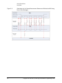
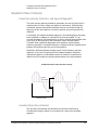
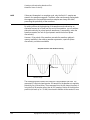
Waveform Phase Continuity . . . . . . . . . . . . . . . . . . . . . . . . . . . . . . . . . . . . . . . . . . . . . . . . . . . . . . . . . . . . . . . . . 5-219
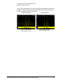
Phase Discontinuity, Distortion, and Spectral Regrowth . . . . . . . . . . . . . . . . . . . . . . . . . . . . . . . . . . . . . . . 5-219
Avoiding Phase Discontinuities. . . . . . . . . . . . . . . . . . . . . . . . . . . . . . . . . . . . . . . . . . . . . . . . . . . . . . . . . . . 5-219
Waveform Memory . . . . . . . . . . . . . . . . . . . . . . . . . . . . . . . . . . . . . . . . . . . . . . . . . . . . . . . . . . . . . . . . . . . . . . . . 5-222
Memory Allocation . . . . . . . . . . . . . . . . . . . . . . . . . . . . . . . . . . . . . . . . . . . . . . . . . . . . . . . . . . . . . . . . . . . . 5-224
Memory Size . . . . . . . . . . . . . . . . . . . . . . . . . . . . . . . . . . . . . . . . . . . . . . . . . . . . . . . . . . . . . . . . . . . . . . . . . 5-226
Commands for Downloading and Extracting Waveform Data. . . . . . . . . . . . . . . . . . . . . . . . . . . . . . . . . . . . . . . 5-228
Waveform Data Encryption . . . . . . . . . . . . . . . . . . . . . . . . . . . . . . . . . . . . . . . . . . . . . . . . . . . . . . . . . . . . . . 5-228
File Transfer Methods . . . . . . . . . . . . . . . . . . . . . . . . . . . . . . . . . . . . . . . . . . . . . . . . . . . . . . . . . . . . . . . . . . 5-229
SCPI Command Line Structure . . . . . . . . . . . . . . . . . . . . . . . . . . . . . . . . . . . . . . . . . . . . . . . . . . . . . . . . . . . 5-230
Commands and File Paths for Downloading and Extracting Waveform Data . . . . . . . . . . . . . . . . . . . . . . . 5-230
FTP Procedures . . . . . . . . . . . . . . . . . . . . . . . . . . . . . . . . . . . . . . . . . . . . . . . . . . . . . . . . . . . . . . . . . . . . . . . 5-234
Creating Waveform Data . . . . . . . . . . . . . . . . . . . . . . . . . . . . . . . . . . . . . . . . . . . . . . . . . . . . . . . . . . . . . . . . . . . 5-238
Code Algorithm . . . . . . . . . . . . . . . . . . . . . . . . . . . . . . . . . . . . . . . . . . . . . . . . . . . . . . . . . . . . . . . . . . . . . . . 5-238
v
Contents
Downloading Waveform Data . . . . . . . . . . . . . . . . . . . . . . . . . . . . . . . . . . . . . . . . . . . . . . . . . . . . . . . . . . . . . . . 5-244
Using Simulation Software . . . . . . . . . . . . . . . . . . . . . . . . . . . . . . . . . . . . . . . . . . . . . . . . . . . . . . . . . . . . . . 5-244
Using Advanced Programming Languages . . . . . . . . . . . . . . . . . . . . . . . . . . . . . . . . . . . . . . . . . . . . . . . . . 5-246
Loading, Playing, and Verifying a Downloaded Waveform . . . . . . . . . . . . . . . . . . . . . . . . . . . . . . . . . . . . . . . . .
Loading a File from Non–Volatile Memory . . . . . . . . . . . . . . . . . . . . . . . . . . . . . . . . . . . . . . . . . . . . . . . . . .
Playing the Waveform . . . . . . . . . . . . . . . . . . . . . . . . . . . . . . . . . . . . . . . . . . . . . . . . . . . . . . . . . . . . . . . . . .
Verifying the Waveform. . . . . . . . . . . . . . . . . . . . . . . . . . . . . . . . . . . . . . . . . . . . . . . . . . . . . . . . . . . . . . . . .
Building and Playing Waveform Sequences. . . . . . . . . . . . . . . . . . . . . . . . . . . . . . . . . . . . . . . . . . . . . . . . .
5-250
5-250
5-250
5-252
5-252
Using the Download Utilities . . . . . . . . . . . . . . . . . . . . . . . . . . . . . . . . . . . . . . . . . . . . . . . . . . . . . . . . . . . . . . . . 5-254
Downloading E443xB Signal Generator Files . . . . . . . . . . . . . . . . . . . . . . . . . . . . . . . . . . . . . . . . . . . . . . . . . . . 5-255
E443xB Data Format . . . . . . . . . . . . . . . . . . . . . . . . . . . . . . . . . . . . . . . . . . . . . . . . . . . . . . . . . . . . . . . . . . . 5-256
SCPI Commands . . . . . . . . . . . . . . . . . . . . . . . . . . . . . . . . . . . . . . . . . . . . . . . . . . . . . . . . . . . . . . . . . . . . . . 5-256
Programming Examples . . . . . . . . . . . . . . . . . . . . . . . . . . . . . . . . . . . . . . . . . . . . . . . . . . . . . . . . . . . . . . . . . . . .
C++ Programming Examples. . . . . . . . . . . . . . . . . . . . . . . . . . . . . . . . . . . . . . . . . . . . . . . . . . . . . . . . . . . . .
MATLAB Programming Examples . . . . . . . . . . . . . . . . . . . . . . . . . . . . . . . . . . . . . . . . . . . . . . . . . . . . . . . . .
Visual Basic Programming Examples . . . . . . . . . . . . . . . . . . . . . . . . . . . . . . . . . . . . . . . . . . . . . . . . . . . . . .
HP Basic Programming Examples . . . . . . . . . . . . . . . . . . . . . . . . . . . . . . . . . . . . . . . . . . . . . . . . . . . . . . . .
5-257
5-258
5-288
5-305
5-312
Troubleshooting Waveform Files . . . . . . . . . . . . . . . . . . . . . . . . . . . . . . . . . . . . . . . . . . . . . . . . . . . . . . . . . . . . . 5-321
Configuring the Pulse/RF Blank . . . . . . . . . . . . . . . . . . . . . . . . . . . . . . . . . . . . . . . . . . . . . . . . . . . . . . . . . . 5-322
6.
Creating and Downloading User–Data Files
Overview . . . . . . . . . . . . . . . . . . . . . . . . . . . . . . . . . . . . . . . . . . . . . . . . . . . . . . . . . . . . . . . . . . . . . . . . . . . . . . . . 6-324
vi
Signal Generator Memory . . . . . . . . . . . . . . . . . . . . . . . . . . . . . . . . . . . . . . . . . . . . . . . . . . . . . . . . . . . . . . . . . .
Memory Allocation . . . . . . . . . . . . . . . . . . . . . . . . . . . . . . . . . . . . . . . . . . . . . . . . . . . . . . . . . . . . . . . . . . . .
Memory Size . . . . . . . . . . . . . . . . . . . . . . . . . . . . . . . . . . . . . . . . . . . . . . . . . . . . . . . . . . . . . . . . . . . . . . . . .
Checking Available Memory . . . . . . . . . . . . . . . . . . . . . . . . . . . . . . . . . . . . . . . . . . . . . . . . . . . . . . . . . . . . .
6-325
6-327
6-328
6-329
User File Data (Bit/Binary) Downloads. . . . . . . . . . . . . . . . . . . . . . . . . . . . . . . . . . . . . . . . . . . . . . . . . . . . . . . . .
User File Bit Order (LSB and MSB) . . . . . . . . . . . . . . . . . . . . . . . . . . . . . . . . . . . . . . . . . . . . . . . . . . . . . . . .
Bit File Type Data . . . . . . . . . . . . . . . . . . . . . . . . . . . . . . . . . . . . . . . . . . . . . . . . . . . . . . . . . . . . . . . . . . . . .
Binary File Type Data . . . . . . . . . . . . . . . . . . . . . . . . . . . . . . . . . . . . . . . . . . . . . . . . . . . . . . . . . . . . . . . . . .
User File Size. . . . . . . . . . . . . . . . . . . . . . . . . . . . . . . . . . . . . . . . . . . . . . . . . . . . . . . . . . . . . . . . . . . . . . . . .
Determining Memory Usage for Custom User File Data . . . . . . . . . . . . . . . . . . . . . . . . . . . . . . . . . . . . . . .
Downloading User Files . . . . . . . . . . . . . . . . . . . . . . . . . . . . . . . . . . . . . . . . . . . . . . . . . . . . . . . . . . . . . . . .
Commands for Bit File Downloads . . . . . . . . . . . . . . . . . . . . . . . . . . . . . . . . . . . . . . . . . . . . . . . . . . . . . . . .
Commands for Binary File Downloads . . . . . . . . . . . . . . . . . . . . . . . . . . . . . . . . . . . . . . . . . . . . . . . . . . . . .
Selecting a Downloaded User File as the Data Source . . . . . . . . . . . . . . . . . . . . . . . . . . . . . . . . . . . . . . . .
Modulating and Activating the Carrier . . . . . . . . . . . . . . . . . . . . . . . . . . . . . . . . . . . . . . . . . . . . . . . . . . . . .
Modifying User File Data. . . . . . . . . . . . . . . . . . . . . . . . . . . . . . . . . . . . . . . . . . . . . . . . . . . . . . . . . . . . . . . .
Real–Time Custom High Data Rates . . . . . . . . . . . . . . . . . . . . . . . . . . . . . . . . . . . . . . . . . . . . . . . . . . . . . .
6-331
6-332
6-332
6-335
6-336
6-337
6-338
6-342
6-343
6-345
6-345
6-345
6-348
Pattern RAM (PRAM) Data Downloads . . . . . . . . . . . . . . . . . . . . . . . . . . . . . . . . . . . . . . . . . . . . . . . . . . . . . . . .
Understanding PRAM Files . . . . . . . . . . . . . . . . . . . . . . . . . . . . . . . . . . . . . . . . . . . . . . . . . . . . . . . . . . . . . .
PRAM File Size . . . . . . . . . . . . . . . . . . . . . . . . . . . . . . . . . . . . . . . . . . . . . . . . . . . . . . . . . . . . . . . . . . . . . . .
SCPI Command for a List Format Download . . . . . . . . . . . . . . . . . . . . . . . . . . . . . . . . . . . . . . . . . . . . . . . .
SCPI Command for a Block Data Download . . . . . . . . . . . . . . . . . . . . . . . . . . . . . . . . . . . . . . . . . . . . . . . .
Selecting a Downloaded PRAM File as the Data Source . . . . . . . . . . . . . . . . . . . . . . . . . . . . . . . . . . . . . . .
Modulating and Activating the Carrier . . . . . . . . . . . . . . . . . . . . . . . . . . . . . . . . . . . . . . . . . . . . . . . . . . . . .
Storing a PRAM File to Non–Volatile Memory and Restoring to Volatile Memory . . . . . . . . . . . . . . . . . . .
6-350
6-350
6-353
6-355
6-355
6-358
6-360
6-360
Contents
Extracting a PRAM File . . . . . . . . . . . . . . . . . . . . . . . . . . . . . . . . . . . . . . . . . . . . . . . . . . . . . . . . . . . . . . . . . 6-360
Modifying PRAM Files . . . . . . . . . . . . . . . . . . . . . . . . . . . . . . . . . . . . . . . . . . . . . . . . . . . . . . . . . . . . . . . . . . 6-362
FIR Filter Coefficient Downloads . . . . . . . . . . . . . . . . . . . . . . . . . . . . . . . . . . . . . . . . . . . . . . . . . . . . . . . . . . . . . 6-364
Data Requirements . . . . . . . . . . . . . . . . . . . . . . . . . . . . . . . . . . . . . . . . . . . . . . . . . . . . . . . . . . . . . . . . . . . . 6-364
Data Limitations . . . . . . . . . . . . . . . . . . . . . . . . . . . . . . . . . . . . . . . . . . . . . . . . . . . . . . . . . . . . . . . . . . . . . . 6-364
Downloading FIR Filter Coefficient Data . . . . . . . . . . . . . . . . . . . . . . . . . . . . . . . . . . . . . . . . . . . . . . . . . . . 6-365
Selecting a Downloaded User FIR Filter as the Active Filter . . . . . . . . . . . . . . . . . . . . . . . . . . . . . . . . . . . . 6-366
Using the Equalization Filter . . . . . . . . . . . . . . . . . . . . . . . . . . . . . . . . . . . . . . . . . . . . . . . . . . . . . . . . . . . . . . . . 6-368
Save and Recall Instrument State Files . . . . . . . . . . . . . . . . . . . . . . . . . . . . . . . . . . . . . . . . . . . . . . . . . . . . . . . . 6-369
Save and Recall SCPI Commands . . . . . . . . . . . . . . . . . . . . . . . . . . . . . . . . . . . . . . . . . . . . . . . . . . . . . . . . 6-369
Save and Recall Programming Example Using VISA and C# . . . . . . . . . . . . . . . . . . . . . . . . . . . . . . . . . . . . 6-370
User Flatness Correction Downloads Using C++ and VISA . . . . . . . . . . . . . . . . . . . . . . . . . . . . . . . . . . . . . . . . . 6-383
Data Transfer Troubleshooting . . . . . . . . . . . . . . . . . . . . . . . . . . . . . . . . . . . . . . . . . . . . . . . . . . . . . . . . . . . . . . . 6-388
User File Download Problems . . . . . . . . . . . . . . . . . . . . . . . . . . . . . . . . . . . . . . . . . . . . . . . . . . . . . . . . . . . . 6-388
PRAM Download Problems . . . . . . . . . . . . . . . . . . . . . . . . . . . . . . . . . . . . . . . . . . . . . . . . . . . . . . . . . . . . . . 6-390
User FIR Filter Coefficient File Download Problems. . . . . . . . . . . . . . . . . . . . . . . . . . . . . . . . . . . . . . . . . . . 6-391
vii
Contents
viii
Keysight Technologies
X-Series Signal Generators
Programming Guide
1
Getting Started with Remote Operation
CAUTION
Keysight does not recommend going backwards in firmware versions (loading
older firmware versions into newer instruments) as hardware/firmware
conflicts can result.
NOTE
Full LXI Class B feature implementation is only available on N51xxA MXG
signal generators. A license may be required to enable this feature and to
download the required firmware versions >A.01.50. For information on new
firmware releases, go to http://www.keysight.com/find/upgradeassistant.
— Programming and Software/Hardware Layers on page 2
— Interfaces on page 3
— IO Libraries and Programming Languages on page 4
— Using the Web Browser on page 12
— Preferences on page 19
— Error Messages on page 21
1
Getting Started with Remote Operation
Programming and Software/Hardware Layers
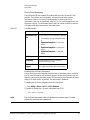
Programming and Software/Hardware Layers
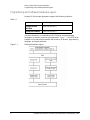
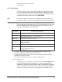
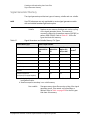
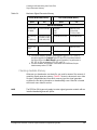
Keysight X-Series signal generators support the following interfaces:
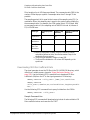
Table 1-1
Instrument
Interfaces Supported
Keysight N51xxB
EXG/MXG
GPIB, LAN, and USB 2.0
Keysight N51xxAMXG
GPIB, LAN, and USB 2.0
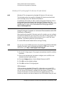
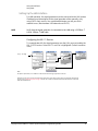
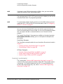
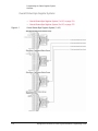
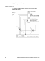
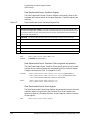
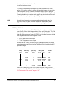
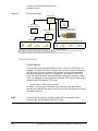
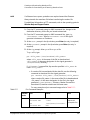
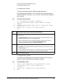
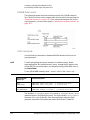
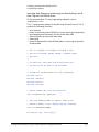
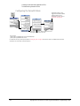
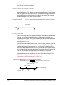
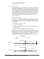
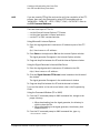
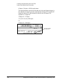
Use these interfaces, in combination with IO libraries and programming
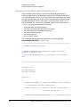
languages, to remotely control a signal generator. Figure 1-1 uses GPIB as an
example of the relationships between the interface, IO libraries, programming
language, and signal generator.
Figure 1-1
2
Software/Hard ware Layers
Keysight EXG and MXG X-Series Signal Generators Programming Guide
Getting Started with Remote Operation
Interfaces
Interfaces
Table 1-2
GPIB
GPIB is used extensively when a dedicated computer is available for remote control of
each instrument or system. Data transfer is fast because GPIB handles information in bytes
with data transfer rates of up to 8 MBps. GPIB is physically restricted by the location and
distance between the instrument/system and the computer; cables are limited to an
average length of two meters per device with a total length of 20 meters.
For more information on configuring the signal generator to communicate over the GPIB,
refer to “Using GPIB” on page 24.
LAN
Data transfer using the LAN is fast as the LAN handles packets of data. The single cable
distance between a computer and the signal generator is limited to 100 meters
(100Base-T and 10Base-T).
The following protocols can be used to communicate with the signal generator over the
LAN:
—
—
—
—
VXI-11 (recommended)
Sockets
TELNET
FTP
The Keysight N51xxA MXG supports LXI Class Ba functionality. The Keysight N51xxB
EXG/MXG supports LXI Class C functionality. For more information on the LXI standards,
refer to http://www.lxistandard.org/home.
For more information on configuring the signal generator to communicate over the LAN,
refer to “Using LAN” on page 30.
USB
— The rear panel Type-B or Mini-B 5-pin connector is a device USB and can
be used to connect a controller for remote operation.
— The Type-A front panel connector is a host USB and can be used to
connect a mouse, a keyboard, or a USB 1.1/2.0 flash drive.
USB 2.0’s 64 MBps communication speed is faster than GPIB for data transfers >1 KB;
however, longer latency makes small USB transfers slower and less efficient than GPIB.
For additional information, refer to the Keysight SICL or VISA User’s Guide.)
For more information on connecting the signal generator to the USB, refer to the
“Keysight IO Libraries Suite” on page 4 and the Keysight Connection Expert in the
Keysight IO Libraries Help.
For more information on configuring the signal generator to communicate over the USB,
refer to “Using USB” on page 60.
a. LXI Class B Compliance testing using IEEE 1588-2008 not available at release.
Keysight EXG and MXG X-Series Signal Generators Programming Guide
3
Getting Started with Remote Operation
IO Libraries and Programming Languages
IO Libraries and Programming Languages
The IO libraries is a collection of functions used by a programming language to
send instrument commands and receive instrument data. Before you can
communicate and control the signal generator, you must have an IO library
installed on your computer. The Keysight IO libraries are included on an
Automation-Ready CD with your signal generator and Keysight GPIB interface
board, or they can be downloaded from the Keysight website:
http://www.keysight.com.
NOTE
To learn about using IO libraries with Windows XP or newer operating
systems, refer to the Keysight IO Libraries Suite’s help located on the
Automation-Ready CD that ships with your signal generator. Other sources of
this information, can be found with the Keysight GPIB interface board’s CD, or
downloaded from the Keysight website: http://www.keysight.com.
To better understand setting up Windows XP operating systems and newer,
using PC LAN port settings, refer to Chapter 2.
Keysight IO Libraries Suite
The Keysight IO Libraries Suite replaces earlier versions of the Keysight IO
Libraries. Keysight IO Libraries Suite does not support Windows NT. If you are
using the Windows NT platform, you must use Keysight IO Libraries version M
or earlier.
CAUTION
The USB interface requires Keysight IO Libraries Suite 14.1 or newer. For
more information on connecting instruments using USB, refer to the Keysight
Connection Expert in the Keysight IO Libraries Help.
NOTE
The signal generator ships with an Automation-Ready CD that contains the
Keysight IO Libraries Suite 14.0 for users who use Windows 98 and Windows
ME. These older systems are no longer supported in Keysight IO Libraries
Suite version 14.1 and higher.
Once the libraries are loaded, you can use the Keysight Connection Expert,
Interactive IO, or VISA Assistant to configure and communicate with the signal
generator over different IO interfaces. Follow instructions in the setup wizard to
install the libraries.
4
Keysight EXG and MXG X-Series Signal Generators Programming Guide
Getting Started with Remote Operation
IO Libraries and Programming Languages
NOTE
Before setting the LAN interface, the signal generator must be configured for
VXI-11 SCPI. Refer to “Configuring the VXI–11 Service” on page 31.
Refer to the Keysight IO Libraries Suite Help documentation for details about
this software.
Keysight EXG and MXG X-Series Signal Generators Programming Guide
5
Getting Started with Remote Operation
IO Libraries and Programming Languages
Windows XP, 2000 Professional and Vista Business Keysight IO
Libraries 15.0 (and Newer)
NOTE
Windows NT is not supported on Keysight IO Libraries 14.0 and newer.
For additional information on older versions of Keysight IO libraries, refer to
the Keysight Connection Expert in the Keysight IO Libraries Help. The
Keysight IO libraries are included with your signal generator or Keysight GPIB
interface board, or they can be downloaded from the Keysight website:
http://www.keysight.com.
VISA Assistant
VISA is an industry standard IO library API. It allows the user to send SCPI
commands to instruments and to read instrument data in a variety of formats.
Refer to the VISA Assistant Help menu and the Keysight VISA User’s Manual
(available on Keysight’s website) for more information.
VISA Configuration (Automatic)
1. Run the VISA Assistant program:
Start > All Programs > Keysight IO Libraries Suite > Keysight Connection
Expert > Tools > Visa Assistant >.
2. Click on the interface you want to use for sending commands to the signal
generator.
3. Click the Formatted I/O tab.
4. Select SCPI in the Instr. Lang. section.
You can enter SCPI commands in the text box and send the command using
the viPrintf button.
6
Keysight EXG and MXG X-Series Signal Generators Programming Guide
Getting Started with Remote Operation
IO Libraries and Programming Languages
Using VISA Configuration (Manual)
Use the Keysight IO Libraries Suite 15.0 to perform the following steps to use
the Connection Expert and VISA to manually configure an interface.
1. Run the Keysight Connection Expert program: Start > All Programs >
Keysight IO Libraries Suite > Keysight Connection Expert >.
2. On the tool bar select the Add Interface button.
3. Click LAN Interface in the Available interface types text box.
4. Click the ADD button.
5. Verify that the Auto (automatically detect protocol) bubble is checked.
Click O.K. to use the default settings.
6. Click LAN(TCPIPO) in the Instrument I/O on this PC text box.
7. On the tool bar select the Add Instrument button.
8. Click the Add Address button in the Add LAN Instruments window.
9. Enter the hostname of the instrument or select the Use IP Address check
box and enter the IP address.
10.Click OK.
Keysight EXG and MXG X-Series Signal Generators Programming Guide
7
Getting Started with Remote Operation
IO Libraries and Programming Languages
Windows NT and Keysight IO Libraries M (and Earlier)
NOTE
Windows NT is not supported on Keysight IO Libraries 14.0 and newer.
The following sections are specific to Keysight IO Libraries versions M and
earlier and apply only to the Windows NT platform.
For additional information on older versions of Keysight IO libraries, refer to
the Keysight Connection Expert in the Keysight IO Libraries Help. The
Keysight IO libraries are included with your signal generator or Keysight GPIB
interface board, or they can be downloaded from the Keysight website:
http://www.keysight.com.
Using IO Config for Computer-to-Instrument Communication with VISA
(Automatic or Manually)
After installing the Keysight IO Libraries version M or earlier, you can configure
the interfaces available on your computer by using the IO Config program. This
program can setup the interfaces that you want to use to control the signal
generator. The following steps set up the interfaces.
1. Install GPIB interface boards before running IO Config.
NOTE
You can also connect GPIB instruments using the Keysight 82357A USB/GPIB
Interface Converter, which eliminates the need for a GPIB card. For more
information, go to http://www.keysight.com/find/gpib.
2. Run the IO Config program. The program automatically identifies available
interfaces.
3. Click on the interface type you want to configure, such as GPIB, in the
Available Interface Types text box.
4. Click the Configure button. Set the Default Protocol to AUTO.
5. Click OK to use the default settings.
6. Click OK to exit the IO Config program.
VISA Assistant
VISA is an industry standard IO library API. It allows the user to send SCPI
commands to instruments and to read instrument data in a variety of formats.
You can use the VISA Assistant, available with the Keysight IO Libraries
versions M and earlier, to send commands to the signal generator. If the
interface you want to use does not appear in the VISA Assistant then you must
8
Keysight EXG and MXG X-Series Signal Generators Programming Guide
Getting Started with Remote Operation
IO Libraries and Programming Languages
manually configure the interface. See the Manual VISA Configuration section
below. Refer to the VISA Assistant Help menu and the Keysight VISA User’s
Manual (available on Keysight’s website) for more information.
VISA Configuration (Automatic)
1. Run the VISA Assistant program.
2. Click on the interface you want to use for sending commands to the signal
generator.
3. Click the Formatted I/O tab.
4. Select SCPI in the Instr. Lang. section.
You can enter SCPI commands in the text box and send the command using
the viPrintf button.
VISA Configuration (Manual)
Perform the following steps to use IO Config and VISA to manually configure an
interface.
1. Run the IO Config Program.
2. Click on GPIB in the Available Interface Types text box.
3. Click the Configure button. Set the Default Protocol to AUTO and then
click OK to use the default settings.
4. Click on GPIB0 in the Configured Interfaces text box.
5. Click Ed it...
6. Click the Ed it VISA Config... button.
7. Click the Add device button.
8. Enter the GPIB address of the signal generator.
9. Click the OK button in this form and all other forms to exit the IO Config
program.
Keysight EXG and MXG X-Series Signal Generators Programming Guide
9
Getting Started with Remote Operation
IO Libraries and Programming Languages
Selecting IO Libraries for GPIB
The IO libraries are included with the GPIB interface card, and can be
downloaded from the National Instruments website or the Keysight website.
See also, “IO Libraries and Programming Languages” on page 4 for
information on IO libraries. The following is a discussion on these libraries.
CAUTION
Because of the potential for portability problems, running Keysight SICL
without the VISA overlay is not recommended by Keysight Technologies.
VISA
VISA is an IO library used to develop IO applications and
instrument drivers that comply with industry standards.
It is recommended that the VISA library be used for
programming the signal generator. The NI-VISA™ and
Keysight VISA libraries are similar implementations of
VISA and have the same commands, syntax, and
functions. The differences are in the lower level IO
libraries; NI-488.2 and SICL respectively. It is best to
use the Keysight VISA library with the Keysight GPIB
interface card or NI-VISA with the NI PCI-GPIB interface
card.
SICL
Keysight SICL can be used without the VISA overlay.
The SICL functions can be called from a program.
However, if this method is used, executable programs
will not be portable to other hardware platforms. For
example, a program using SICL functions will not run on
a computer with NI libraries (PCI-GPIB interface card).
NI-488.2
NI-488.2 can be used without the VISA overlay. The
NI-488.2 functions can be called from a program.
However, if this method is used, executable programs
will not be portable to other hardware platforms. For
example, a program using NI-488.2 functions will not
run on a computer with Keysight SICL (Keysight GPIB
interface card).
Selecting IO Libraries for LAN
The TELNET and FTP protocols do not require IO libraries to be installed on
your computer. However, to write programs to control your signal generator,
an IO library must be installed on your computer and the computer configured
for instrument control using the LAN interface.
.
10
NI-VISA is a registered trademark of National Instruments Corporation.
Keysight EXG and MXG X-Series Signal Generators Programming Guide
Getting Started with Remote Operation
IO Libraries and Programming Languages
The Keysight IO libraries Suite is available on the Automation-Ready CD, which
was shipped with your signal generator. The libraries can also be downloaded
from the Keysight website. The following is a discussion on these libraries.
Keysight VISA
VISA is an IO library used to develop IO applications and
instrument drivers that comply with industry standards.
Use the Keysight VISA library for programming the
signal generator over the LAN interface.
SICL
Keysight SICL is a lower level library that is installed
along with Keysight VISA.
Programming Languages
Along with Standard Commands for Programming Instructions (SCPI) and IO
library functions, you use a programming language to remotely control the
signal generator. Common programming languages include:
—
—
—
—
—
—
—
C/C++
C#
MATLAB® (MATLAB is a registered trademark of The MathWorks.)
HP Basic
LabView
Java™ (Java is a U.S. trademark of Sun Microsystems, Inc.)
Visual Basic® (Visual Basic is a registered trademark of Microsoft
Corporation.)
— PERL
— Keysight VEE
For examples, using some of these languages, refer to Chapter 3.
Keysight EXG and MXG X-Series Signal Generators Programming Guide
11
Getting Started with Remote Operation
Using the Web Browser
Using the Web Browser
NOTE
The following example for accessing the Web-Enabled X-Series web page
uses the newly shipped instrument’s predetermined default hostname
(a-<instrument model number>-<last 5 d igits of the instrument serial
number>).
The procedure that follows assumes the signal generator is running firmware
A.01.20 or later.
MXG Web-Enabled SCPI command capability is not available for versions of
Internet Explorer ≥7.0. (The SCPI Telnet softkey is inactive for these
versions.) To use the Telnet SCPI, refer to the figure on page 13.
For more information on LAN Connectivity, refer to the Keysight Connectivity
Guide (E2094-90009) or to the LAN Connectivity FAQs for details on using the
instrument over LAN.
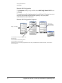
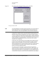
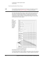
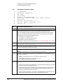
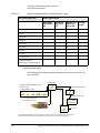
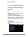
The instrument can be accessed through a standard web browser, when it is
connected to the LAN. To access through the web browser, enter the
instrument IP address or the hostname as the URL in your browser. Refer to
Figure 1-2, “The Signal Generator Web Service” on page 13.
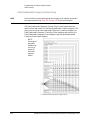
The signal generator web page, shown at right and page 16, provides general
information on the signal generator, FTP access to files stored on the signal
generator, and a means to control the instrument using either a remote
front-panel interface or SCPI commands. The web page also has links to
Keysight’s products, support, manuals, and website. For additional information
on memory catalog access (file storing), and FTP, refer to the User’s Guide and
“Waveform Memory” on page 222 and for FTP, see “Using FTP” on page 44
and “FTP Procedures” on page 234.
The Web Server service is compatible with the Microsoft Internet Explorer (6.0
and newer) web browser and operating systems Windows 2000, Windows XP,
and newer. For more information on using the Web Server, refer to “Enabling
the Signal Generator Web Server” on page 15.
12
Keysight EXG and MXG X-Series Signal Generators Programming Guide
Getting Started with Remote Operation
Using the Web Browser
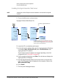
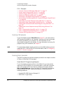
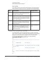
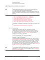
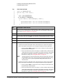
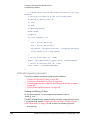
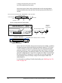
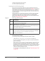
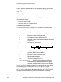
Figure 1-2
The Signal Generator Web Service
The Keysight N51xxA MXG supports LXI Class B* functionality. The Keysight N51xxB
EXG/MXG supports LXI Class C functionality. For more information on the LXI standards,
refer to http://www.lxistandard.org/home.
*Option ALB on the MXG enables LAN LXI class B compliance. This option is included
standard on all new MXG’s shipped since June 2009. MXG’s shipped before June 2009 can
be upgraded by ordering option N51xxAK-ALB. Contact Keysight for more details.
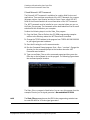
To operate the signal generator, click the
keys.
NOTE: If you do not see this window,
check to see if the window is hidden behind your browser window or your web browser
settings are set to block pop-ups. To use this feature, you need to set your web browser to
allow pop-ups for your instrument’s IP address.
Remote SCPI commands requires the Telnet feature on the computer. The Telnet feature
is available from a variety of sources. Some software updates can block (break) this Telnet
connection (e.g. Internet Explorer 7). When using Internet Explorer as a browser, only
versions <Internet Explorer 7 enable the Web-Enabled MXG SCPI feature.
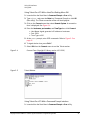
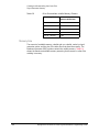
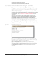
Modifying the Signal Generator Configuration
NOTE
Use Help with this Page for assistance with the Web-Enabled interface.
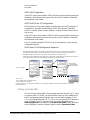
1. From the welcome page of the Web-Enabled interface, click View &
Mod ify Configuration to show the instrument’s currently assigned IP
address and other parameters.
Keysight EXG and MXG X-Series Signal Generators Programming Guide
13
Getting Started with Remote Operation
Using the Web Browser
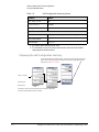
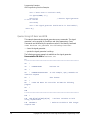
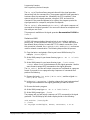
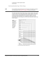
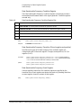
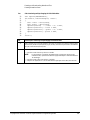
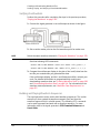
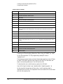
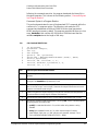
2. Enter the new settings and click Save.
3. Click Renew LAN Settings to cause the new settings to take effect.
Figure 1-3
14
View & Modify Configuration
Keysight EXG and MXG X-Series Signal Generators Programming Guide
Getting Started with Remote Operation
Using the Web Browser
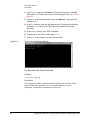
Enabling the Signal Generator Web Server
NOTE
Javascript or Active Scripts must be enabled to use the web front panel
controls.
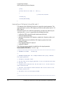
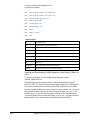
1. Turn on the Web server as shown below.
Keysight X-Series Web Server On
If necessary, toggle Web Server to
On.
For details on each key and for equivalent SCPI commands,
use the key help. Refer to “Getting Key Help” on page 19 and
the User’s Guide. For additional SCPI command information,
refer to the SCPI Command Reference.
2. Launch the PC or workstation web browser.
3. In the web browser address field, enter the signal generator’s IP address.
For example, http://101.101.101.101 (where 101.101.101.101 is the
signal generator’s IP address).
The IP (internet protocol) address can change depending on the LAN
configuration (see “Using LAN” on page 30).
4. On the computer’s keyboard, press Enter. The web browser displays the
signal generator’s homepage.
5. Click the Signal Generator Web Control menu button on the left of the
page. The LXI password box is displayed on the computer. Refer to the
Web-Enabled MXG Help.
6. Click Submit.
7. The front panel web page displays.
Keysight EXG and MXG X-Series Signal Generators Programming Guide
15
Getting Started with Remote Operation
Using the Web Browser
NOTE
If you are experiencing problems with opening the signal generator’s
remote front panel web page, verify that the pop-up blocker is turned off on
your web browser.
In some cases the Web-Enabled front panel may appear behind the main
browser window, so you must move the browser window to see the
Web-Enabled front panel.
To control the signal generator, either click the front panel keys or enter
SCPI commands.
FTP enables the transfer
of files between the
instrument and a
computer. The FTP
access button provides
drag-and-drop file
capability.
The FTP access button opens a window that displays the signal
generator’s memory catalog files.
Use the FTP window to drag and drop files from the FTP page to
your computer.
16
Keysight EXG and MXG X-Series Signal Generators Programming Guide
Getting Started with Remote Operation
Using the Web Browser
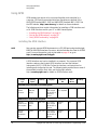
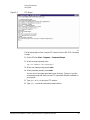
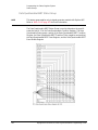
LAN Configuration System Defaults
NOTE
The instrument’s LAN configuration system information can be found on the
signal generator’s homepage and on the signal generator. Refer to “Enabling
the Signal Generator Web Server” on page 15 and to “Displaying the LAN
Configuration Summary” on page 18.
If the instrument has been restored to the factory defaults from the LAN Setup
menu the signal generator will revert to the values displayed in Table on page 17.
Refer to “Displaying the LAN Configuration Summary” on page 18.
To reset the instrument LXI password to “agilent” and the LAN settings to their
factory default values, press the following key sequence on the signal
generator:
Utility > I/O Config > LAN Setup > Ad vanced Settings > More 2 of 2 >
Restore LAN Settings to Default Values > Confirm Restore LAN Settings to
Default Values
NOTE
There are no SCPI commands associated with this LXI password factory reset.
For more information, refer to the signal generator’s Web Server Interface
Help.
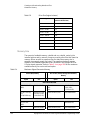
Table 1-3
LAN Configuration Summary Values
Parameter
Defaul t
Signal Generator LAN Configuration Summary
Hostname:
Keysight–<model number>–<last_5_chars_of_serial_number>
Config Type:
AUTO
IP Address:
127.0.0.1
Connection
Monitoring:
On
Subnet:
255.255.255.0
DNS Server Override:
Off
Gateway:
0.0.0.0
Dynamic DNS Naming:
On
RFC NETBIOS Naming:
On
DNS Server:
0.0.0.0
Keysight EXG and MXG X-Series Signal Generators Programming Guide
17
Getting Started with Remote Operation
Using the Web Browser
Table 1-3
LAN Configuration Summary Values
Parameter
Defaul t
TCP Keep Alive:
On
Domain Name:a
<empty>
TCP Keep Alive Timeout:
1800.0 sec
Signal Generator Web Server Interface
Description:
Keysight <model_number>(<serial_number>)
SICL Interface Nameb:
gpib0
Web Password:
agilent
a. The Domain Name defaults to a null field.
b. This information is part of the “Advanced Information about this Web-Enabled
<signal generator model number>”
Displaying the LAN Configuration Summary
Confirm Restore Settings to Factory Defaults: Confirming this action configures the signal
generator to its original factory default settings. For information regarding those default
settings, refer to Table 1-3 on page 17.
Utility > IO Config
SCPI command:
Not applicable
For details on each key and for equivalent SCPI commands (if applicable),
use the key help (described in the User’s Guide).
18
Keysight EXG and MXG X-Series Signal Generators Programming Guide
Getting Started with Remote Operation
Preferences
Preferences
The following commonly-used manual command sections are included here:
“Configuring the Display for Remote Command Setups” on page 19
“Getting Key Help” on page 19
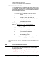
Configuring the Display for Remote Command Setups
Select Update in Remote until On is
highlighted.
SCPI commands:
:DISPlay:REMote ON|OFF|1|0
:DISPlay:REMote?
For details on each key and for equivalent SCPI commands (if applicable), use the key help (described below and in the User’s Guide).
Getting Key Help
When you press the front-panel Help button:
Help displays for the next key you press.
The “key help” includes a description of the key’s functionality and a list of equivalent SCPI
commands (if they exist). This feature is especially useful if you are building a SCPI program
based on front-panel key presses.
Use the cursor keys, Page Up, Page Down, and the RPG knob to scroll the help text. Then
press Cancel to close the help window or press any other key to close the help window and
execute that key.
For details on each key and for equivalent SCPI commands (if applicable), use the key help (described in User’s Guide).
Keysight EXG and MXG X-Series Signal Generators Programming Guide
19
Getting Started with Remote Operation
Troubleshooting
Troubleshooting
In each section of this document, there is information that is related to
troubleshooting that topic, if applicable. Refer to those corresponding sections
in this document as well as to the User’s Guide, before using the diagnostics
mode referred to in the Service Guide and in the caution below.
CAUTION
All X-Series signal generators have a fail-safe and diagnostic mode that
should only be used if all other troubleshooting mentioned in this document
has been attempted and failed. If the diagnostic mode is determined to be
needed, refer to the Service Guide.
NOTE
If the LAN Reset hardkey has been pressed and then the power is cycled on
the instrument, the web-server will be enabled after reboot.
20
Keysight EXG and MXG X-Series Signal Generators Programming Guide
Getting Started with Remote Operation
Error Messages
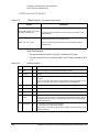
Error Messages
If an error condition occurs in the signal generator, it is reported to both the
SCPI (remote interface) error queue and the front panel display error queue.
These two queues are viewed and managed separately; for information on the
front panel display error queue, refer to the User’s Guide.
For additional general information on troubleshooting problems with your
connections, refer to the Help in the Keysight IO Libraries and documentation.
NOTE
When accessing error messages using the SCPI (remote interface) error queue,
the error numbers and the <error_description> portions of the error query
response are displayed on the host terminal.
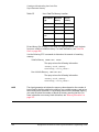
Characteristic
SCPI Remote Interface Error Queue
Capacity (#errors)
30
Overflow Handling
Linear, first-in/first-out.
Replaces newest error with: -350, Queue overflow
Viewing Entriesa
Use SCPI query SYSTem:ERRor[:NEXT]?
Clearing the Queueb
Power up
Send a *CLS command
Read last item in the queue
Unresolved Errorsc
Re-reported after queue is cleared.
No Errors
When the queue is empty (every error in the queue has been read, or the queue is cleared), the
following message appears in the queue:
+0, "No error"
a. Using this SCPI command to read out the error messages clears the display of the ERR
annunciator and the error message at the bottom of the screen.
b. Executing the SCPI command *CLS clears the display of the ERR annunciator and the error
message at the bottom of the screen.
c. Errors that still exist after clearing the error queue. For example, unlock.
Error Message File
A complete list of error messages is provided in the file errormessages.pd f, on
the CD-ROM supplied with your instrument. In the error message list, an
explanation is generally included with each error to further clarify its meaning.
The error messages are listed numerically. In cases where there are multiple
listings for the same error number, the messages are in alphabetical order.
Keysight EXG and MXG X-Series Signal Generators Programming Guide
21
Getting Started with Remote Operation
Error Messages
Error Message Types
Events generate only one type of error. For example, an event that generates a
query error will not generate a device-specific, execution, or command error.
Query Errors (–499 to –400) indicate that the instrument’s output queue
control has detected a problem with the message exchange protocol described
in IEEE 488.2, Chapter 6. Errors in this class set the query error bit (bit 2) in the
event status register (IEEE 488.2, section 11.5.1). These errors correspond to
message exchange protocol errors described in IEEE 488.2, 6.5. In this case:
— Either an attempt is being made to read data from the output queue when
no output is either present or pending, or
— data in the output queue has been lost.
Device Specific Errors (–399 to –300, 201 to 703, and 800 to 810) indicate
that a device operation did not properly complete, possibly due to an abnormal
hardware or firmware condition. These codes are also used for self-test
response errors. Errors in this class set the device-specific error bit (bit 3) in the
event status register (IEEE 488.2, section 11.5.1).
The <error_message> string for a positive error is not defined by SCPI. A
positive error indicates that the instrument detected an error within the GPIB
system, within the instrument’s firmware or hardware, during the transfer of
block data, or during calibration.
Execution Errors (–299 to –200) indicate that an error has been detected by
the instrument’s execution control block. Errors in this class set the execution
error bit (bit 4) in the event status register (IEEE 488.2, section 11.5.1). In this
case:
— Either a <PROGRAM DATA> element following a header was evaluated by
the device as outside of its legal input range or is otherwise inconsistent
with the device’s capabilities, or
— a valid program message could not be properly executed due to some
device condition.
Execution errors are reported after rounding and expression evaluation
operations are completed. Rounding a numeric data element, for example, is
not reported as an execution error.
Command Errors (–199 to –100) indicate that the instrument’s parser
detected an IEEE 488.2 syntax error. Errors in this class set the command error
bit (bit 5) in the event status register (IEEE 488.2, section 11.5.1). In this case:
— Either an IEEE 488.2 syntax error has been detected by the parser (a
control-to-device message was received that is in violation of the IEEE
488.2 standard. Possible violations include a data element that violates
device listening formats or whose type is unacceptable to the device.), or
— an unrecognized header was received. These include incorrect
device-specific headers and incorrect or unimplemented IEEE 488.2
common commands.
22
Keysight EXG and MXG X-Series Signal Generators Programming Guide
Keysight Technologies
X-Series Signal Generators
Programming Guide
2
Using IO Interfaces
Using the programming examples with GPIB, LAN, and USB interfaces:
— Using GPIB on page 24
— Using LAN on page 30
— Using USB on page 60
23
Using IO Interfaces
Using GPIB
Using GPIB
GPIB enables instruments to be connected together and controlled by a
computer. GPIB and its associated interface operations are defined in the
ANSI/IEEE Standard 488.1–1987 and ANSI/IEEE Standard 488.2–1992. See
the IEEE website, http://www.ieee.org, for details on these standards.
The following sections contain information for installing a GPIB interface card
or NI–GPIB interface card for your PC or UNIX–based system.
— “Installing the GPIB Interface” on page 24
— “Set Up the GPIB Interface” on page 25
— “Verify GPIB Functionality” on page 26
Installing the GPIB Interface
You can also connect GPIB instruments to a PC USB port using the Keysight
82357A USB/GPIB Interface Converter, which eliminates the need for a GPIB
card. For more information, refer to the table on page 24 or go to
http://www.keysight.com/find/gpib.
NOTE
A GPIB interface card can be installed in a computer. Two common GPIB
interface cards are the Keysight GPIB interface card and the National
Instruments (NI) PCI–GPIB card. Follow the interface card instructions for
installing and configuring the card. The following table provide lists on some of
the available interface cards. Also, see the Keysight website,
http://www.keysight.com for details on GPIB interface cards.
Interface
Type
Operating
System
IO Library
Languages
Backplane/
BUS
Max IO
(kB/sec)
Buffering
USB/GPIB Interface Converter for PC–Based Systems
Keysight
82357A
Converter
Windows
98(SE)/ME/
2000/XP
VISA / SICL
C/C++, Visual
Basic, Keysight
VEE, HP Basic for
Windows, NI
Labview
USB 2.0
(1.1 compatible
)
850
Built–in
GPIB Interface Card for PC–Based Systems
24
Keysight
82341C for ISA
bus computers
Windows
95/98/NT
/2000
VISA / SICL
C/C++, Visual
Basic, Keysight
VEE, HP Basic for
Windows
ISA/EISA,
16 bit
750
Built–in
Keysight
82341D
Plug&Play for
PC
Windows
95
VISA / SICL
C/C++, Visual
Basic, Keysight
VEE, HP Basic for
Windows
ISA/EISA,
16 bit
750
Built–in
Keysight EXG and MXG X-Series Signal Generators Programming Guide
Using IO Interfaces
Using GPIB
Interface
Type
Operating
System
IO Library
Languages
Backplane/
BUS
Max IO
(kB/sec)
Buffering
USB/GPIB Interface Converter for PC–Based Systems
Keysight
82350A for PCI
bus computers
Windows
95/98/NT
/2000
VISA / SICL
C/C++, Visual
Basic, Keysight
VEE, HP Basic for
Windows
PCI 32 bit
750
Built–in
Keysight
82350B for PCI
bus computers
Windows
98(SE)/ME/200
0/XP
VISA / SICL
C/C++, Visual
Basic, Keysight
VEE, HP Basic for
Windows
PCI 32 bit
> 900
Built–in
NI–GPIB Interface Card for PC–Based Systems
National
Instruments
PCI–GPIB
Windows
95/98/2000/
ME/NT
VISA
NI–488.2 a
C/C++,
Visual BASIC,
LabView
PCI 32 bit
1.5 MBps
Built–in
National
Instruments
PCI–GPIB+
Windows
NT
VISA
NI–488.2
C/C++,
Visual BASIC,
LabView
PCI 32 bit
1.5 MBps
Built–in
GPIB Interface Card for HP–UX Workstations
Keysight
E2071C
HP–UX 9.x,
HP–UX 10.01
VISA/SICL
ANSI C,
Keysight VEE,
HP BASIC,
HP–UX
EISA
750
Built–in
Keysight
E2071D
HP–UX 10.20
VISA/SICL
ANSI C,
Keysight VEE,
HP BASIC,
HP–UX
EISA
750
Built–in
Keysight
E2078A
HP–UX 10.20
VISA/SICL
ANSI C,
Keysight VEE,
HP BASIC,
HP–UX
PCI
750
Built–in
a. NI–488.2 is a trademark of National Instruments Corporation.
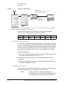
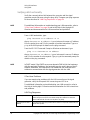
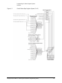
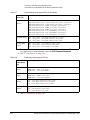
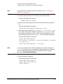
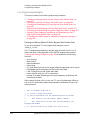
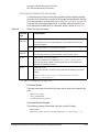
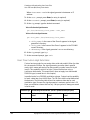
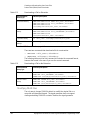
Set Up the GPIB Interface
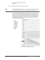
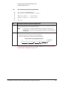
Enter the GPIB address as shown in Figure 2-1.
Keysight EXG and MXG X-Series Signal Generators Programming Guide
25
Using IO Interfaces
Using GPIB
Figure 2-1
Setting the GPIB Address
SCPI commands:
:SYSTem:COMMunicate:GPIB:ADDRess <number>
:SYSTem:COMMunicate:GPIB:ADDRess?
Default address: 19
Range: 0–30
For details on each key, use the key help. Refer to “Getting Key Help” on page 19 and the User’s Guide. For additional SCPI
command information, refer to the SCPI Command Reference.
Connect a GPIB interface cable between the signal generator and the
computer. (The following table lists cable part numbers.)
Model
10833A
10833B
10833C
10833D
10833F
10833G
Length
1 meter
2 meters
4 meters
.5 meter
6 meters
8 meters
Verify GPIB Functionality
To verify GPIB functionality, use the VISA Assistant, available with the Keysight
IO Library or the Getting Started Wizard available with the National Instrument
IO Library. These utility programs enable you to communicate with the signal
generator and verify its operation over GPIB. For information and instructions
on running these programs, refer to the Help menu available in each utility.
If You Have Problems
1. Verify that the signal generator’s address matches the address declared in
the program (example programs in Chapter 3).
2. Remove all other instruments connected through GPIB and rerun the
program.
3. Verify that the GPIB card’s name or id number matches the GPIB name or
id number configured for your PC.
GPIB Interface Terms
An instrument that is part of a GPIB network is categorized as a listener, talker,
or controller, depending on its current function in the network.
listener
26
A listener is a device capable of receiving data or
commands from other instruments. Several instruments
in the GPIB network can be listeners simultaneously.
Keysight EXG and MXG X-Series Signal Generators Programming Guide
Using IO Interfaces
Using GPIB
talker
A talker is a device capable of transmitting data. To
avoid confusion, a GPIB system allows only one device
at a time to be an active talker.
controller
A controller, typically a computer, can specify the talker
and listeners (including itself) for an information
transfer. Only one device at a time can be an active
controller.
Keysight EXG and MXG X-Series Signal Generators Programming Guide
27
Using IO Interfaces
GPIB Programming Interface Examples
GPIB Programming Interface Examples
NOTE
The portions of the programming examples discussed in this section are
taken from the full text of these programs that can be found in Chapter 3,
“Programming Examples.”
— “Interface Check using HP Basic and GPIB” on page 28
— “Interface Check Using NI–488.2 and C++” on page 29
Before Using the GPIB Examples
If the Keysight GPIB interface card is used, the Keysight VISA library should be
installed along with Keysight SICL. If the National Instruments PCI–GPIB
interface card is used, the NI–VISA library along with the NI–488.2 library
should be installed. Refer to “Selecting IO Libraries for GPIB” on page 10 and
the documentation for your GPIB interface card for details.
HP Basic addresses the signal generator at 719. The GPIB card is addressed at
7 and the signal generator at 19. The GPIB address designator for other
libraries is typically GPIB0 or GPIB1.
The following sections contain HP Basic and C++ lines of programming
removed from the programming interface examples in Chapter 3,
“Programming Examples.” these portions of programming demonstrate the
important features to consider when developing programming for use with the
GPIB interface.
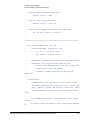
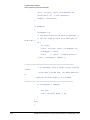
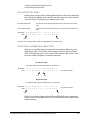
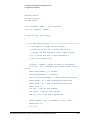
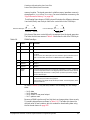
Interface Check using HP Basic and GPIB
This portion of the example program “Interface Check using HP Basic and
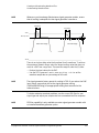
GPIB” on page 28, causes the signal generator to perform an instrument reset.
The SCPI command *RST places the signal generator into a pre–defined state
and the remote annunciator (R) appears on the front panel display.
The following program example is available on the signal generator
Documentation CD–ROM as basicex1.txt. For the full text of this program, refer
to “Interface Check using HP Basic and GPIB” on page 74 or to the signal
generator’s documentation CD–ROM.
28
160
Sig_gen=719
generator's address
! Declares a variable to hold the signal
170
! Places the signal generator into Local mode
LOCAL Sig_gen
180
CLEAR Sig_gen
parser
! Clears any pending data I/O and resets the
190
REMOTE 719
! Puts the signal generator into remote mode
200
CLEAR SCREEN
! Clears the controllers display
Keysight EXG and MXG X-Series Signal Generators Programming Guide
Using IO Interfaces
GPIB Programming Interface Examples
210
REMOTE 719
220
OUTPUT Sig_gen;"*RST"
defined state
! Places the signal generator into a
Interface Check Using NI–488.2 and C++
This portion of the example program “Interface Check Using NI–488.2 and
C++” on page 29, uses the NI–488.2 library to verify that the GPIB connections
and interface are functional.
The following program example is available on the signal generator
Documentation CD–ROM as niex1.cpp. For the full text of this program, refer
to “Interface Check Using NI-488.2 and C++” on page 75 or to the signal
generator’s documentation CD–ROM.
#include "stdafx.h"
#include <iostream>
#include "windows.h"
#include "Decl-32.h"
using namespace std;
int GPIB0=
0;
// Board handle
Addr4882_t Address[31]; // Declares an array of type Addr4882_t
int main(void)
{
int sig;
variable
// Declares a device descriptor
sig = ibdev(0, 19, 0, 13, 1, 0); // Aquires a device descriptor
ibclr(sig);
to signal generator
ibwrt(sig, "*RST", 4);
into a defined state
// Sends device clear message
// Places the signal generator
Keysight EXG and MXG X-Series Signal Generators Programming Guide
29
Using IO Interfaces
Using LAN
Using LAN
The signal generator can be remotely programmed through a 100Base–T LAN
interface or 10Base–T LAN interface and LAN–connected computer using one
of several LAN interface protocols. The LAN allows instruments to be
connected together and controlled by a LAN–based computer. LAN and its
associated interface operations are defined in the IEEE 802.2 standard. For
more information refer to http://www.ieee.org.
NOTE
For more information on configuring your signal generator for LAN, refer to
the User’s Guide for your signal generator. You can also refer to
www.keysight.com and search on the FAQs: Hard ware Configurations and
Installation.
The signal generator supports the following LAN interface protocols:
—
—
—
—
—
VXI–11 (See page 38)
Sockets LAN (See page 39)
Telephone Network (TELNET) (See page 40)
File Transfer Protocol (FTP) (See page 44)
LXI (See page 46)
VXI–11 and sockets LAN are used for general programming using the LAN
interface, TELNET is used for interactive, one command at a time instrument
control, and FTP is for file transfer. LXI is used to communicate with multiple
instruments through LAN events using precision time protocols.
For more information on the LXI standards, refer to www.keysight.com/find/lxi.
NOTE
For more information on configuring the signal generator to communicate
over the LAN, refer to “Using VXI–11” on page 38.
The following sections contain information on selecting and connecting IO
libraries and LAN interface hardware that are required to remotely program the
signal generator through LAN to a LAN–based computer and combining those
choices with one of several possible LAN interface protocols.
— “Setting Up the LAN Interface” on page 31
— “Verifying LAN Functionality” on page 34
30
Keysight EXG and MXG X-Series Signal Generators Programming Guide
Using IO Interfaces
Using LAN
Setting Up the LAN Interface
For LAN operation, the signal generator must be connected to the LAN, and an
IP address must be assigned to the signal generator either manually or by
using DHCP client service. Your system administrator can tell you which
method to use. (Most modern LAN networks use DHCP.)
Verify that the signal generator is connected to the LAN using a 100Base–T
LAN or 10Base–T LAN cable.
NOTE
Configuring the VXI–11 Service
To communicate with the signal generator over the LAN, you must enable the
VXI–11 SCPI service. Select VXI–11 until On is highlighted. (Default condition
is On.)
Utility > IO Config
NOTE
For optimum performance, use a 100Base–T LAN cable to connect the signal generator to the LAN.
For details on each key or for a list of equivalent SCPI commands, use the front-panel key help. For information describing the
key help, refer to “Getting Key Help” on page 19 and the User’s Guide. For additional SCPI command information, refer to the
SCPI Command Reference.
Keysight EXG and MXG X-Series Signal Generators Programming Guide
31
Using IO Interfaces
Using LAN
Manual LAN Configuration
The Hostname softkey is only available when LAN Config Manual DHCP is set
to Manual.
To remotely access the signal generator from a different LAN subnet, you must
also enter the subnet mask and default gateway. See your system
administrator for more information.
Manual LAN Configuration Sequence
MXG-A signal
generator models
only (not X-Series)
Utility > IO Config
Your hostname can be up to 20 characters long.
SCPI commands:
:SYSTem:COMMunicate:LAN:CONFig MANual
:SYSTem:COMMunicate:LAN:CONFig?
For details on each key, use the key help (described in User’s Guide). For additional SCPI command information, refer to the SCPI
Command Reference.
32
Keysight EXG and MXG X-Series Signal Generators Programming Guide
Using IO Interfaces
Using LAN
DHCP LAN Configuration
If the DHCP server uses dynamic DNS to link the hostname with the assigned
IP address, the hostname may be used in place of the IP address. Otherwise,
the hostname is not usable.
AUTO (DHCP/Auto–IP) Configuration
DHCP and Auto–IP are used together to make automatic (AUTO) mode for IP
configuration. Automatic mode attempts DHCP first and then if that fails
Auto–IP is used to detect a private network. If neither is found, Manual is the
final choice.
If the DHCP server uses dynamic DNS to link the hostname with the assigned
IP address, the hostname may be used in place of the IP address. Otherwise,
the hostname is not usable.
Auto–IP provides automatic TCP/IP set–up for instruments on any manually
configured networks.
DHCP/Auto-IP LAN Configuration Sequence
AUTO (DHCP/Auto–IP): Request a new IP address in the following sequence: 1) from the DHCP (server–based LAN), 2)
Auto–IP (private network without a network administrator) or if neither is available, 3) Manual setting is selected.
DHCP (MXG-A models only): Request a new IP address from the DHCP server each power cycle.
Confirming this action configures the signal generator as a DHCP client. In DHCP mode, the signal generator will request a
new IP address from the DHCP server upon rebooting to determine the assigned IP address.
MXG-A signal
generator models
only (not X-Series)
Utility > IO Config
SCPI commands:
:SYSTem:COMMunicate:LAN:CONFig DHCP|AUTO
:SYSTem:COMMunicate:LAN:CONFig?
For details on each key, use the key help (described in User’s Guide). For additional SCPI command information, refer to the SCPI
Command Reference.
Setting up Private LAN
You can connect the Keysight X-Series signal generator directly to a PC using
a crossover cable. To do this, you should either choose to set IP addresses of
the PC and signal generator to differ only in the last digit (example: PC’s IP:
1.1.1.1 and Signal generator’s IP: 1.1.1.2); or you can use the DHCP feature or
Auto–IP feature if your PC supports them. For more information go to
www.keysight.com, and search on the Connectivity Guide (E2094–90009) or
use the Keysight Connection Expert’s Help to see the Connection Guide.
Keysight EXG and MXG X-Series Signal Generators Programming Guide
33
Using IO Interfaces
Using LAN
Verifying LAN Functionality
Verify the communications link between the computer and the signal
generator remote file server using the ping utility. Compare your ping response
to those described in “LAN Ping Responses” on page 34.
NOTE
For additional information on troubleshooting your LAN connection, refer to
“If You Have Problems” on page 34 and to the Help in the Keysight IO
Libraries and documentation for LAN connections and problems.
From a UNIX workstation, type:
ping <hostname or IP address> 64 10
where <hostname or IP address> is your instrument’s name or IP address,
64 is the packet size, and 10 is the number of packets transmitted. Type man
ping at the UNIX prompt for details on the ping command.
From the MS–DOS Command Prompt or Windows environment, type:
ping -n 10 <hostname or IP address>
where <hostname or IP address> is your instrument’s name or IP address
and 10 is the number of echo requests. Type ping at the command prompt for
details on the ping command.
NOTE
In DHCP mode, if the DHCP server uses dynamic DNS to link the hostname
with the assigned IP address, the hostname may be used in place of the IP
address. Otherwise, the hostname is not usable and you must use the IP
address to communicate with the signal generator over the LAN.
If You Have Problems
If you are experiencing problems with the LAN connection on the signal
generator, verify the rear panel LAN connector green LED is on.
For additional information on troubleshooting your LAN connection, refer to
the Help in the Keysight IO Libraries and documentation for LAN connections
and problems.
LAN Ping Responses
34
Normal Response for UNIX
A normal response to the ping command will be a total of 9 or 10 packets received with a
minimal average round–trip time. The minimal average will be different from network to
network. LAN traffic will cause the round–trip time to vary widely.
Normal Response for DOS or
Windows
A normal response to the ping command will be a total of 9 or 10 packets received if 10 echo
requests were specified.
Keysight EXG and MXG X-Series Signal Generators Programming Guide
Using IO Interfaces
Using LAN
Error Messages
If error messages appear, then check the command syntax before continuing with
troubleshooting. If the syntax is correct, resolve the error messages using your network
documentation or by consulting your network administrator.
If an unknown host error message appears, try using the IP address instead of the hostname.
Also, verify that the host name and IP address for the signal generator have been registered by
your IT administrator.
Check that the hostname and IP address are correctly entered in the node names database. To
do this, enter the nslookup <hostname> command from the command prompt.
No Response
If there is no response from a ping, no packets were received. Check that the typed address or
hostname matches the IP address or hostname assigned to the signal generator in the System
LAN Setup menu. For more information, refer to “DHCP/Auto-IP LAN Configuration
Sequence” on page 33.
Ping each node along the route between your workstation and the signal generator, starting
with your workstation. If a node doesn’t respond, contact your IT administrator.
If the signal generator still does not respond to ping, you should suspect a hardware problem.
— Check the signal generator LAN connector lights
— Verify the hostname is not being used with DHCP addressing
Intermittent Response
If you received 1 to 8 packets back, there maybe a problem with the network. In networks with
switches and bridges, the first few pings may be lost until these devices ‘learn’ the location of
hosts. Also, because the number of packets received depends on your network traffic and
integrity, the number might be different for your network. Problems of this nature are best
resolved by your IT department.
Using Interactive IO
Use the VISA Assistant utility available in the Keysight IO Libraries Suite to
verify instrument communication over the LAN interface. Refer to the section
on the “IO Libraries and Programming Languages” on page 4 for more
information.
The Keysight IO Libraries Suite is supported on all platforms except Windows
NT. If you are using Windows NT, refer to the section below on using the VISA
Assistant to verify LAN communication. See the section on “Windows NT and
Keysight IO Libraries M (and Earlier)” on page 8 for more information.
NOTE
The following sections are specific to Keysight IO Libraries versions M and
earlier and apply only to the Windows NT platform.
Keysight EXG and MXG X-Series Signal Generators Programming Guide
35
Using IO Interfaces
Using LAN
Using VISA Assistant
Use the VISA Assistant, available with the Keysight IO Library versions M and
earlier, to communicate with the signal generator over the LAN interface.
However, you must manually configure the VISA LAN client. Refer to the Help
menu for instructions on configuring and running the VISA Assistant program.
1. Run the IO Config program.
2. Click on TCPIP0 in the Available Interface Types text box.
3. Click the Configure button. Then Click OK to use the default settings.
4. Click on TCPIP0 in the Configured Interfaces text box.
5. Click Ed it...
6. Click the Ed it VISA Config... button.
7. Click the Add device button.
8. Enter the TCPIP address of the signal generator. Leave the Device text box
empty.
9. Click the OK button in this form and all subsequent forms to exit the IO
Config program.
If You Have Problems
1. Verify the signal generator’s IP address is valid and that no other
instrument is using the IP address.
2. Switch between manual LAN configuration and DHCP using the front
panel LAN Config softkey and run the ping program using the different IP
addresses.
NOTE
36
For Keysight IO Libraries versions M and earlier, you must manually configure
the VISA LAN client in the IO Config program if you want to use the VISA
Assistant to verify LAN configuration. Refer to the IO Libraries Installation
Guide for information on configuring IO interfaces. The IO Config program
interface is shown in Figure 2-3 on page 39.
Keysight EXG and MXG X-Series Signal Generators Programming Guide
Using IO Interfaces
Using LAN
Figure 2-2
IO Config Form (Windows NT)
Check to see that the Default Protocol is set to Automatic.
1. Run the IO Config program.
2. Click on TCPIP in the Configured Interfaces text box. If there is no TCPIP0
in the box, follow the steps shown in the section “Using VISA Assistant” on
page 36.
3. Click the Ed it button.
4. Click the radio button for AUTO (automatically detect protocol).
5. Click OK, OK to end the IO Config program.
Keysight EXG and MXG X-Series Signal Generators Programming Guide
37
Using IO Interfaces
Using LAN
Using VXI–11
The signal generator supports the LAN interface protocol described in the
VXI–11 standard. VXI–11 is an instrument control protocol based on Open
Network Computing/Remote Procedure Call (ONC/RPC) interfaces running
over TCP/IP. It is intended to provide GPIB capabilities such as SRQ (Service
Request), status byte reading, and DCAS (Device Clear State) over a LAN
interface. This protocol is a good choice for migrating from GPIB to LAN as it
has full Keysight VISA/SICL support.
NOTE
It is recommended that the VXI–11 protocol be used for instrument
communication over the LAN interface.
Configuring for VXI–11
The Keysight IO library has a program, IO Config, that is used to setup the
computer/signal generator interface for the VXI–11 protocol. Download the
latest version of the Keysight IO library from the Keysight website. Refer to the
Keysight IO library user manual, documentation, and Help menu for
information on running the IO Config program and configuring the VXI–11
interface.
Use the IO Config program to configure the LAN client. Once the computer is
configured for a LAN client, you can use the VXI–11 protocol and the VISA
library to send SCPI commands to the signal generator over the LAN interface.
Example programs for this protocol are included in “LAN Programming
Interface Examples” on page 117 of this programming guide.
NOTE
To communicate with the signal generator over the LAN interface you must
enable the VXI–11 SCPI service. For more information, refer to
“DHCP/Auto-IP LAN Configuration Sequence” on page 33.
If you are using the Windows NT platform, refer to “Windows NT and Keysight
IO Libraries M (and Earlier)” on page 8 for information on using Keysight IO
Libraries versions M or earlier to configure the interface.
For Keysight IO library version J.01.0100, the “Identify devices at run–time”
check box must be unchecked. Refer to Figure 2-3.
38
Keysight EXG and MXG X-Series Signal Generators Programming Guide
Using IO Interfaces
Using LAN
Figure 2-3
Show Devices Form (Keysight IO Library version J.01.0100)
Using Sockets LAN
NOTE
Users with Windows XP operating systems and newer can use this section to
better understand how to use the signal generator with port settings. For
more information, refer to the help software of the IO libraries being used.
Sockets LAN is a method used to communicate with the signal generator over
the LAN interface using the Transmission Control Protocol/Internet Protocol
(TCP/IP). A socket is a fundamental technology used for computer networking
and allows applications to communicate using standard mechanisms built into
network hardware and operating systems. The method accesses a port on the
signal generator from which bidirectional communication with a network
computer can be established.
Sockets LAN can be described as an internet address that combines Internet
Protocol (IP) with a device port number and represents a single connection
between two pieces of software. The socket can be accessed using code
libraries packaged with the computer operating system. Two common versions
of socket libraries are the Berkeley Sockets Library for UNIX systems and
Winsock for Microsoft operating systems.
Your signal generator implements a sockets Applications Programming
Interface (API) that is compatible with Berkeley socket for UNIX systems, and
Winsock for Microsoft systems. The signal generator is also compatible with
other standard sockets APIs. The signal generator can be controlled using SCPI
commands that are output to a socket connection established in your program.
Keysight EXG and MXG X-Series Signal Generators Programming Guide
39
Using IO Interfaces
Using LAN
Before you can use sockets LAN, you must select the signal generator’s
sockets port number to use:
— Standard mode. Available on port 5025. Use this port for simple
programming.
— TELNET mode. The telnet SCPI service is available on port 5024.
NOTE
For MXG firmware versions A.01.51 and later, the default telnet port is 5024.
Telnet port 5023 is still available for backwards compatibility. Refer to the
SCPI Command Reference.
An example using sockets LAN is given in “LAN Programming Interface
Examples” on page 117 of this programming guide.
Using Telnet LAN
Telnet provides a means of communicating with the signal generator over the
LAN. The Telnet client, run on a LAN connected computer, will create a login
session on the signal generator. A connection, established between computer
and signal generator, generates a user interface display screen with SCPI>
prompts on the command line.
Using the Telnet protocol to send commands to the signal generator is similar
to communicating with the signal generator over GPIB. You establish a
connection with the signal generator and then send or receive information
using SCPI commands. Communication is interactive: one command at a time.
NOTE
Some systems use a command prompt style interface for the Telnet client.
Refer to the Figure 2-6 on page 42 for an example of this interface.
For Windows XP and newer, use this section to better understand how to use
the signal generator with port settings. For more information, refer to the help
software of the IO libraries being used.
For Windows 7, Telnet functionality is disabled by default. To enable Telnet,
got to Start > Control Panel > Programs and Features > Turn Windows
features on or off and select the Telnet Client checkbox. Click OK and restart
your PC.
The following telnet LAN connections are discussed:
— “Using Telnet On a PC With a Host/Port Setting Menu GUI” on page 41
— “Using Telnet On a PC With a Command Prompt Interface” on page 41
— “The Standard UNIX Telnet Command” on page 42
A Telnet example is provided in “Unix Telnet Example” on page 44.
40
Keysight EXG and MXG X-Series Signal Generators Programming Guide
Using IO Interfaces
Using LAN
Using Telnet On a PC With a Host/Port Setting Menu GUI
1. Launch either the Start Menu’s Command Prompt or Run utility.
2. Type Telnet and press the Enter key (Command Prompt) or click OK
(Run utility). The Telnet connection screen will be displayed.
3. Click on the Connect menu then select Remote System. A connection
form is displayed. See Figure 2-4.
4. Enter the hostname, port number, and TermType then click Connect.
— Host Name−signal generator’s IP address or hostname
— Port−5024
— Term Type−vt100
5. At the SCPI> prompt, enter SCPI commands. Refer to Figure 2-5 on
page 41.
6. To signal device clear, press Ctrl–C.
7. Select Exit from the Connect menu to end the Telnet session.
Figure 2-4
Figure 2-5
Connect Form (Keysight IO Library version J.01.0100)
Telnet Window
Using Telnet On a PC With a Command Prompt Interface
1. Launch either the Start Menu’s Command Prompt or Run utility.
Keysight EXG and MXG X-Series Signal Generators Programming Guide
41
Using IO Interfaces
Using LAN
2. Type Telnet and press the Enter key (Command Prompt) or click OK
(Run utility). The Telnet client screen will be displayed. See Figure 2-6 on
page 42.
3. Type open at the prompt and then press the Enter key. The prompt will
change to (to).
4. At the (to) prompt, enter the signal generator’s IP address followed by a
space and 5024, which is the Telnet port associated with the signal
generator.
5. At the SCPI> prompt, enter SCPI commands.
6. To escape from the SCPI> session type Ctrl-].
7. Type quit at the prompt to end the Telnet session.
Figure 2-6
Telnet Command Prompt Window
The Standard UNIX Telnet Command
Synopsis
telnet [host [port]]
Description
This command is used to communicate with another host using the Telnet
protocol. When the command telnet is invoked with host or port
arguments, a connection is opened to the host, and
42
Keysight EXG and MXG X-Series Signal Generators Programming Guide
Using IO Interfaces
Using LAN
input is sent from the user to the host.
Options and Parameters
The command telnet operates in character–at–a–time or line–by–line mode.
In line–by–line mode, typed text is echoed to the screen. When the line is
completed (by pressing the Enter key), the text line is sent to host. In
character–at–a–time mode, text is echoed to the screen and sent to host as it
is typed. At the UNIX prompt, type man telnet to view the options and
parameters available with the telnet command.
NOTE
If your Telnet connection is in line–by–line mode, there is no local echo. This
means you cannot see the characters you are typing until you press the Enter
key. To remedy this, change your Telnet connection to
character–by–character mode. Escape out of Telnet, and at the telnet>
prompt, type mode char. If this does not work, consult your Telnet program's
documentation.
Keysight EXG and MXG X-Series Signal Generators Programming Guide
43
Using IO Interfaces
Using LAN
Unix Telnet Example
To connect to the instrument with host name myInstrument and port number
5024, enter the following command on the command line: telnet
myInstrument 5024.
When you connect to the signal generator, the UNIX window will display a
welcome message and a SCPI command prompt. The instrument is now ready
to accept your SCPI commands. As you type SCPI commands, query results
appear on the next line. When you are done, break the Telnet connection using
an escape character. For example, Ctrl-],where the control key and the] are
pressed at the same time. The following example shows Telnet commands:
$ telnet myinstrument 5024
Trying....
Connected to signal generator
Escape character is ‘^]’.
Keysight Technologies, N51xx SN-US00000001
Firmware:
Hostname: your instrument
IP :xxx.xx.xxx.xxx
SCPI>
Using FTP
FTP allows users to transfer files between the signal generator and any
computer connected to the LAN. For example, you can use FTP to download
instrument screen images to a computer. When logged onto the signal
generator with the FTP command, the signal generator’s file structure can be
accessed. Figure 2-7 shows the FTP interface and lists the directories in the
signal generator’s user level directory.
NOTE
44
File access is limited to the signal generator’s /user directory.
Keysight EXG and MXG X-Series Signal Generators Programming Guide
Using IO Interfaces
Using LAN
Figure 2-7
FTP Screen
The following steps outline a sample FTP session from the MS–DOS Command
Prompt:
1. On the PC click Start > Programs > Command Prompt.
2. At the command prompt enter:
ftp < IP address > or < hostname >
3. At the user name prompt, press enter.
4. At the password prompt, press enter.
You are now in the signal generator’s user directory. Typing help at the
command prompt will show you the FTP commands that are available on
your system.
5. Type quit or bye to end your FTP session.
6. Type exit to end the command prompt session.
Keysight EXG and MXG X-Series Signal Generators Programming Guide
45
Using IO Interfaces
Using LAN
Using LXI Class B Features (N51xxA MXG Signal Generators Only)
NOTE
Full LXI Class B feature implementation is only available on N51xxA MXG
signal generators. A license may be required to enable this feature and to
download the required firmware versions >A.01.50. For information on new
firmware releases, go to http://www.keysight.com/find/upgradeassistant.
This section does not apply to N51xxB EXG/MXG signal generators, which are
LXI Class C-compliant instruments.
This section assumes general familiarity with the LXI-B class of instruments
and aims to clarify a number of general use cases for measurement
synchronization between an MXA signal analyzer and an N51xxA MXG signal
generator using a LAN connection. Refer to
http://www.lxistandard.org/home and www.keysight.com/find/lxi for more
information.
This LXI section contains the following:
— “IEEE 1588” on page 46
— “Peer to Peer Messaging” on page 49
— “Configuring LXI Triggers” on page 51
— “Using the LXI Event Log” on page 52
— “Setting up and executing a list sweep measurement” on page 52
— “Synchronize a List Sweep Measurement Between an MXA and an MXG
using Peer to Peer Messages” on page 53
— “For More Information” on page 59
IEEE 1588
The IEEE 1588 standard defines a Precision Time Protocol (PTP) for
synchronizing various clocks connected by Ethernet. This will give your
measurement instrumentation a common sense of time. To ensure that the
MXA and MXG are operating with synchronized PTP clocks, follow the
procedure outlined in the table below.
Time Synchronization using an MXA Signal Analyzer and a MXG Signal
Generator
To ensure that the MXA and MXG are operating with synchronized PTP clocks,
follow this procedure:
1. Connect the MXA and MXG to the same Ethernet switch and the ensure
that both instruments are configured for LAN operation.
2. Power on the MXA and MXG.
3. Send the following SCPI command to both the MXA and MXG:
46
Keysight EXG and MXG X-Series Signal Generators Programming Guide
Using IO Interfaces
Using LAN
:LXI:CLOCk:PTP:DOMain 1
This parameter may be any integer between 0 to 127. The default value is
0.
Keysight EXG and MXG X-Series Signal Generators Programming Guide
47
Using IO Interfaces
Using LAN
Verifying Time Synchronization
To verify that both instruments are running PTP, open the Interactive LXI
tool from a PC which is connected to the same switch as the MXA and MXG.
This program is bundled with the Keysight IO Libraries Suite.
1. Open Interactive LXI.
From a PC connected to the same subnet as the instrument go to: Start >
All Programs > Keysight IO Libraries Suite > Utilities > Interactive LXI.
2. Open the Timing menu.
Click on the tab labeled Timing.
3. Choose an active domain.
From the Active Domain pull down menu, select the PTP domain entered
in step 3 of the previous procedure.
4. Update the clocks.
Click Update Clock List.
5. Check that the MXA and MXG are located in the expected domain.
Click on the Clock Names listed in the Clock List, then examine the Clock
Information panel for the IP Addresses of the MXA and MXG.
6. View the PTP LAN traffic.
Click the PTP Messages tab and select the Timing Messages checkbox.
48
Keysight EXG and MXG X-Series Signal Generators Programming Guide
Using IO Interfaces
Using LAN
Peer to Peer Messaging
The MXA and MXG are capable of sending and receiving LXI specific LAN
packets. The packets are configurable, and may be sent when various
instrument events occur during a measurement or state recall. Each
instrument event has an associated sense of 0 or 1 to indicate whether or not
the event is active. The instrument events that can cause an MXG to send an
LXI LAN packet are summarized in the table below.
Table 2-1
LXI LAN Packets
Instrument Event
Description
OperationComp
lete
Indicates whether or not an operation is underway.
— For example, a single sweep will result
in:
— OperationComplete = 1 before the
sweep.
— OperationComplete = 0 during the
sweep.
— OperationComplete = 1 after the
sweep.
Settling
Indicates the instrument is settling.
Sweeping
Indicates whether or not the instrument is
currently performing a sweep.
Waiting For
Trigger
Indicates whether or not the instrument is waiting
for a trigger event before a measurement begins.
Enabling the LXI Event Subsystem
Due to the high priority response time demands of handling events, enabling
the LXI event subsystem can adversely impact certain specifications such as
frequency and power switching speed. This becomes more noticeable at higher
rates of LXI event traffic. By default, the subsystem is disabled.
To enable the LXI event subsystem from the front panel:
— Press Utility > More > LXI–B > LXI–B Enabled
To enable or disable the LXI event subsystem from SCPI:
— :LXI:STATe ON|OFF
NOTE
The LXI Event subsystem state is a persistent instrument state; it is not
affected by normal preset operations.
Keysight EXG and MXG X-Series Signal Generators Programming Guide
49
Using IO Interfaces
Using LAN
Using the Front Panel to Configure LXI Events
The MXG can be configured to send output LAN events for the pre–defined LXI
events through the front panel softkeys.
1. Press Utility > More > LXI–B > Configure LXI Events > Configure LXI
Output Events
2. From the Output Events menu:
Press Select Source. Choose the instrument status event to be used as a
source for the output LAN event.
3. Press Toggle Event State to enable the highlighted output LAN event.
Using SCPI to configure an LXI Output Events
More configuration options and the ability to configure custom events are
available to the system integrator through SCPI commands. The following
procedure provides a minimum set of commands to configure an output
LAN event. Refer to the SCPI Command Reference.
1. Reset the MXG:
Send the following SCPI command:
*RST
2. Set the LXI Output LAN Event’s source:
Send the following SCPI command:
:LXI:EVENt:LAN:SOURce "LAN0", "Sweeping"
3. Enable the LXI Output Event:
Send the following SCPI command:
:LXI:EVENt:LAN:ENABled "LAN0", 1
Verifying LXI Output LAN Events using LXI Interactive
Peer to peer message transmission can be verified by running LXI
Interactive from a PC on the same subnet as the MXA.
1. From a PC connected to the same subnet as the instrument, go to Start
> All Programs > Keysight IO Libraries Suite > Utilities > Interactive LXI.
2. Click the Start button in the LXI Event Receive box.
3. Incoming LAN Events will be displayed in the text box.
If the initial setup had been configured using the front panel as on
page 49 or SCPI commands (page 50), two LAN Events are expected
per sweep: the rising and falling edges of the LAN Event "LAN0".
50
Keysight EXG and MXG X-Series Signal Generators Programming Guide
Using IO Interfaces
Using LAN
Configuring LXI Triggers
The MXA and MXG are capable of reacting to incoming LXI LAN Events. Both
instruments may be triggered by the receipt of a peer to peer message.
Using the front panel to configure an LXI Trigger on the MXG
The MXG is capable of reacting to an incoming LXI LAN Event by treating it as
a trigger. The following procedure describes how to set up the MXG sweep
trigger to use an LXI event through the front panel soft keys.
1. Select the LXI LAN trigger as the source for sweep triggers.
Press Sweep > More > Sweep Trigger > More > LXI LAN
2. Select a Trigger LAN Event.
Press Utility > More > LXI–B > Configure LXI Events > Configure LXI
Trigger Events
3. Enable the Trigger LAN Event.
Press the Toggle Event State softkey.
Using SCPI to configure an LXI Trigger on the MXG
The MXG is capable of reacting to an incoming LXI LAN Event by treating it as
a trigger. The following procedure describes how to set up the MXG sweep
trigger to use an LXI event through SCPI commands.
1. Reset the MXG
Send the following SCPI command:
*RST
2. Select the LXI LAN trigger as the source for sweep triggers.
Send the following SCPI command:
:TRIGger:SOURce LAN3
3. Enable a Trigger LAN Event.
Send the following SCPI command:
:TRIGger:LXI:LAN:ENABled "LAN0",1
Verifying an LXI Trigger using LXI Interactive
Peer to peer message transmission can be verified by running LXI Interactive
from a PC on the same subnet as the MXG.
1. Open Interactive LXI.
From a PC connected to the same subnet as the instrument, go to Start >
All Programs > Keysight IO Libraries Suite > Utilities > Interactive LXI.
Keysight EXG and MXG X-Series Signal Generators Programming Guide
51
Using IO Interfaces
Using LAN
2. Choose LAN Event.
Select the desired LAN trigger from the Event ID dropdown menu.
3. Send LAN Event.
Press the Send button. This puts the trigger out on the line.
4. Monitor Response as on page 50.
This may be done assuming that the Output LAN event had been
configured from the front panel (page 49) or SCPI commands (page 50).
Using the LXI Event Log
The LXI subsystem also provides an Event Log. The event log records all of
the enabled LXI Event and Instrument Event activity and associates each
action with an IEEE 1588 timestamp. Instrument Events are enabled by default,
and will therefore appear in the log. Since many instrument events occur
during every sweep, logging all of them may flood the event log. They may be
disabled by sending the SCPI command:
:LXI:EVENt:STATus:ENABled “instrumentEvent”,0
where the parameter “instrumentEvent” may be any event listed in Table
2-1. Note that the event must be re–enabled before being used as the source
of an LXI Output LAN Event.
To view the LXI Event Log from the front panel, press the hard key System and
then the softkeys Show, LXI, LXI Event Log. Once the Event Log is displayed,
the arrow keys may be used to scroll through the list. The Event Log may also
be queried through SCPI command.
Setting up and executing a list sweep measurement
The following examples will illustrate procedures for setting up and executing a
list sweep measurement using an MXA and an MXG synchronized with LXI.
Before launching into the procedure, it is important to understand the theory
behind the method. The MXA and MXG use their LXI Output LAN Events to
communicate internal state changes to each other. In the following
synchronization, the rising edge of the Waiting For Trigger instrument
event will be used to communicate to the other device that the next step may
be executed.
For clarity, the MXG's Waiting For Trigger instrument event is mapped to
the LAN0 output event. Likewise, the MXA's Waiting For Trigger
instrument event is mapped to the LAN1 output event. The MXA is configured
to trigger when it receives the LAN0 event with a rising edge. The MXG is
configured to trigger when it receives the LAN1 event with a rising edge. Also,
the OperationComplete output event is enabled, which has the
OperationComplete instrument event mapped to it by default.
52
Keysight EXG and MXG X-Series Signal Generators Programming Guide
Using IO Interfaces
Using LAN
The MXG's list sweep is started first, causing it to source the first signal in its
list. We then start the MXA's list sweep. The OperationComplete instrument
event transitions low, causing an OperationComplete output event to go out
on the LAN with a falling edge. The MXA takes a measurement at the first
frequency in its list. When the MXA has finished its measurement, it moves on
to the next entry in its list. The Waiting For Trigger instrument event
transitions high, causing a LAN1 output event to go out onto the LAN with a
rising edge, and the MXA waits for its next trigger.
The MXG receives the LAN1 event and triggers. The MXG's
Waiting For Trigger instrument event transitions low, and a LAN0 output
event goes onto the LAN with a falling edge. The MXA takes no action, since it
is configured to trigger only on rising edges. The MXG is now sourcing the next
signal in its list. Once that signal has settled, it prepares to move on to its list's
next entry. The MXG's Waiting For Trigger instrument event transitions
high, and a LAN0 output event goes onto the LAN with a rising edge. The MXG
waits for its next trigger.
The MXA receives the LAN0 event and triggers. The MXA's
Waiting For Trigger instrument event transitions low, and a LAN1 output
event goes onto the LAN with a falling edge. The MXG takes no action, since it
is configured to trigger only on rising edges. The MXA completes its
measurement and prepares to move on to the next frequency in its list. The
MXA's Waiting For Trigger instrument event transitions high, and a LAN1
output event goes onto the LAN with a rising edge. The MXA waits for its next
trigger.
The two instruments continue to step through their lists until the MXA has
completed measurements at every frequency in its list. Once the final
measurement has completed, the OperationComplete instrument event
transitions high, causing the OperationComplete output event to go out
onto the LAN with a rising edge. This event may be caught by a controller to
signal the end of the measurement. The controller may then retrieve the list
sweep measurement results from the MXA.
Synchronize a List Sweep Measurement Between an MXA and an MXG
using Peer to Peer Messages
1. Disable LXI Output LAN Events on the MXG:
Send the following SCPI command:
:LXI:EVENt:OUTPut:LAN:DISable:ALL
2. Reset the MXG:
Send the following SCPI command:
*RST
3. Choose the MXG's PTP domain:
Send the following SCPI command:
Keysight EXG and MXG X-Series Signal Generators Programming Guide
53
Using IO Interfaces
Using LAN
:LXI:CLOCk:PTP:DOMain 0
The parameter may be any integer between 0 to 127.
4. Choose the MXG's LXI domain:
Send the following SCPI command:
:LXI:EVENt:DOMain 0
The parameter may be any integer between 0 to 127.
5. Preset the MXG's list sweep:
Send the following SCPI command:
:LIST:TYPE:LIST:INIT:PRES
6. Sets the MXG to expect a list of frequencies:
Send the following SCPI command:
:FREQ:MODE LIST
7. Sets the MXG to expect a list of powers:
Send the following SCPI command:
:POW:MODE LIST
8. Sets the MXG how the lists will be entered:
Send the following SCPI command:
:LIST:TYPE LIST
An arbitrary list will be used instead of range and step size arguments.
9. Send the MXG a list of frequencies:
Send the following SCPI command:
:LIST:FREQ 100MHz,200MHz,300MHz,400MHz,500MHz
The MXG will put out signals at these frequencies and in this order.
10.Send the MXG a list of powers:
Send the following SCPI command:
:LIST:POW 0dBm,-1dBm,-2dBm,-3dBm,-4dBm
The MXG will put out signals at these powers and in this order.
11.Turn off MXG signal modulation:
Send the following SCPI command:
:OUTP:MOD OFF
12.Turn MXG signal output on:
Send the following SCPI command:
54
Keysight EXG and MXG X-Series Signal Generators Programming Guide
Using IO Interfaces
Using LAN
:OUTP ON
13.Configure the MXG's LXI Output LAN Event:
Send the following SCPI commands:
:LXI:EVENt:OUTPut:LAN:DRIVe "LAN0",NORMal
:LXI:EVENt:OUTPut:LAN:SLOPe "LAN0",POS
:LXI:EVENt:OUTPut:LAN:SOURce "LAN0","Waiting For Trigger"
Together, these commands will cause the MXG to send a "LAN0" peer to
peer message every time the “Waiting For Trigger” instrument event
changes state.
14.Set the MXG's trigger source:
Send the following SCPI command:
:LIST:TRIG:SOUR LAN
15.Enable the MXG's LXI LAN Event trigger:
Send the following SCPI command:
:TRIG:LXI:LAN:ENABled "LAN1",1
16.Enable the MXG's LXI Output LAN Event:
Send the following SCPI command:
:LXI:EVENt:OUTPut:LAN:ENABled "LAN0",1
17.Disable LXI Output LAN Events on the MXA:
Send the following SCPI command:
:LXI:EVENt:OUTPut:LAN:DISable:ALL
18.Put the MXA into SA mode:
Send the following SCPI command:
:INST:SEL SA
19.Put the MXA into single sweep mode:
Send the following SCPI command:
:INIT:CONT OFF
20.Choose the MXA's PTP domain:
Send the following SCPI command:
:LXI:CLOCk:PTP:DOMain 0
The parameter value should match the one used in step 3.
21.Choose the MXA's LXI domain:
Send the following SCPI command:
Keysight EXG and MXG X-Series Signal Generators Programming Guide
55
Using IO Interfaces
Using LAN
:LXI:EVENt:DOMain 0
The parameter value should match the one used in step 4.
22.Move the MXA into the list sweep measurement:
Send the following SCPI command:
:CONF:LIST
23.Send the MXA a list of frequencies:
Send the following SCPI command:
:LIST:FREQ 100MHz,200MHz,300MHz,400MHz,500MHz
The MXA will put out signals at these frequencies and in this order.
24.Configure the MXA's list sweep parameters:
Send the following SCPI commands:
:LIST:ATT 10dB
:LIST:BAND:RES:TYPE FLAT
:LIST:BAND:RES 300kHz
:LIST:BAND:VID 3MHz
:LIST:SWE:TIME 1e-6 s
:LIST:TRIG:DEL 0
:LIST:DET RMS
25.Make sure the MXA's LXI LAN triggers are disabled:
Send the following SCPI command:
:TRIG:LXI:LAN:DISable:ALL
26.Set the MXA's trigger source to LXI LAN:
Send the following SCPI command:
:LIST:TRIG:SOUR LAN
27.Configure the MXA's LXI Output LAN Event:
Send the following SCPI commands:
:LXI:EVENt:OUTPut:LAN:DRIVe "LAN1",NORMal
:LXI:EVENt:OUTPut:LAN:SLOPe "LAN1",POS
:LXI:EVENt:OUTPut:LAN:SOURce "LAN1","WaitingForTrigger"
This will cause the MXA to take a measurement at the first frequency in its
list. It will also begin waiting for the "LAN0" peer to peer message before
moving on to the next measurement.
28.Enable the MXA's LXI LAN Event trigger:
56
Keysight EXG and MXG X-Series Signal Generators Programming Guide
Using IO Interfaces
Using LAN
Send the following SCPI commands:
:TRIG:LXI:LAN:ENABled "LAN0",1
29.Enable the MXA's "OperationComplete" LXI Output LAN Event:
Send the following SCPI commands:
:LXI:EVENt:OUTPut:LAN:ENABled "OperationComplete",1
The MXA will send an "OperationComplete" peer to peer message when
the "OperationComplete" instrument event changes state.
30.Begin the MXG's list sweep:
Send the following SCPI commands:
:INIT:CONT ON
This will cause the MXG to put out a signal at the first frequency in its list.
It will also begin waiting for the "LAN1" peer to peer message before
moving on to the next signal.
31.Begin the MXA's list sweep:
Send the following SCPI commands:
:INIT:LIST
This will cause the MXA to take a measurement at the first frequency in its
list. It will also begin waiting for the "LAN0" peer to peer message before
moving on to the next measurement.
32.Enable the MXA's “LAN1” LXI Output LAN Event:
Send the following SCPI commands:
:LXI:EVENt:OUTPut:LAN:ENABled "LAN1",1
The "LAN1" peer to peer message is now enabled.
33.Send the MXG a "LAN1" peer to peer message:
Using Interactive LXI or the Keysight IO Libraries TMFramework LXI
library: send a "LAN1" peer to peer message to the MXG.
This will start the synchronization sequence.
34.The MXA waits for the "OperationComplete" instrument event:
Detect the peer to peer traffic using Interactive LXI. To programmatically
listen for LXI peer to peer messages, use the Keysight IO Libraries
TMFramework LXI library.
When the MXA has completed its list, it will send the peer to peer
message "OperationComplete" with a rising edge to MXG.
35.Send query to MXA for the measurement results:
:FETCh:LIST?
Keysight EXG and MXG X-Series Signal Generators Programming Guide
57
Using IO Interfaces
Using LAN
Figure 2-8
58
Illustration of a List Sweep Measurement Between an MXA and an MXG using
Peer to Peer Messages.
Keysight EXG and MXG X-Series Signal Generators Programming Guide
Using IO Interfaces
Using LAN
For More Information
For more information on using LXI see the Keysight website dedicated to LXI
instrumentation:
www.keysight.com/find/lxi.
Keysight LXI Application Notes:
— Using LXI to go beyond GPIB, PXI and VXI (AN 1465–20)
— 10 Good Reasons to Switch to LXI (AN 1465–21)
— Transitioning from GPIB to LXI (AN 1465–22)
— How to Use VXI and PXI in Your New LXI Test System (AN 1465–23)
— Using Synthetic Instruments in Your Test System (AN 1465–24)
— Migrating system software from GPIB to LAN/LXI (AN 1465–25)
— Modifying a GPIB System to Include LAN/LXI (AN 1465–26)
Keysight EXG and MXG X-Series Signal Generators Programming Guide
59
Using IO Interfaces
Using USB
Using USB
CAUTION
USB cables are not industrial graded and potentially allows data loss in noisy
environments.
USB cables do not have a latching mechanism and the cables can be pulled
out of the PC or instrument relatively easily.
The maximum length for USB cables is 30 m, including the use of inline
repeaters.
NOTE
The USB 2.0 interface supports USBTMC or USBTMC–USB488 specifications.
For more information on connecting instruments to the USB, refer to the
Keysight Connection Expert in the Keysight IO Libraries Help.
USB 2.0 connectors can be used to communicate with the signal generator.
N51xxA MXG signal generators are equipped with a Mini–B 5 pin rear panel
connector (device USB). N51xxB EXG/MXG signal generators are equipped
with a Type-B rear panel connector (device USB). Use a Type–A to Mini–USB 5
pin cable to connect the signal generator to the computer (Refer to “Setting
Up the USB Interface” on page 61). Connect the Type–A front panel connector
(host USB) can be used to connect a mouse, a keyboard, or a USB 1.1/2.0 flash
drive (USB media). (Refer to the User’s Guide.) ARB waveform encryption of
proprietary information is supported. Many functions provided by GPIB,
including GET, non–SCPI remote languages, and remote mode are available
using the USB interface.
NOTE
For a list of compatible flash drives to use with the USB external interface.
Refer to http://www.keysight.com/find/mxg.
Do not use the front panel USB (Type-A) connector to connect to a computer.
The following sections contain information on selecting and connecting I/O
libraries and the USB interface that are required to remotely program the signal
generator through the computer and combining those choices with one of
several possible USB interface protocols.
— “Selecting I/O Libraries for USB” on page 61
— “Setting Up the USB Interface” on page 61
— “Verifying USB Functionality” on page 62
60
Keysight EXG and MXG X-Series Signal Generators Programming Guide
Using IO Interfaces
Using USB
Selecting I/O Libraries for USB
CAUTION
The Keysight X-Series USB interface requires Keysight IO Libraries Suite 14.1
or newer to run properly. For more information on connecting instruments to
the USB, refer to the Keysight Connection Expert in the Keysight IO Libraries
Help.
The I/O libraries can be downloaded from the National Instrument website,
http://www.ni.com, or Keysight’s website, http://www.keysight.com. The
following is a discussion on these libraries.
NOTE
CAUTION
I/O applications such as IVI–COM or VXIplug&play can be used in place of
VISA.
VISA
VISA is an I/O library used to develop I/O applications
and instrument drivers that comply with industry
standards. It is recommended that the VISA library be
used for programming the signal generator. The
NI–VISA and Keysight VISA libraries are similar
implementations of VISA and have the same
commands, syntax, and functions. The differences are in
the lower level I/O libraries used to communicate over
the USB; NI–488.2 and SICL respectively.
NI–488.2
NI–488.2 I/O libraries can be used to develop
applications for the USB interface. See National
Instrument’s website for information on NI–488.2.
SICL
Keysight SICL can be used to develop applications for
the USB interface. See Keysight’s website for
information on SICL.
Because of the potential for portability problems, running Keysight SICL
without the VISA overlay is not recommended by Keysight Technologies.
Setting Up the USB Interface
Rear Panel Interface (Mini–B 5 pin)
To use USB, connect the USB cable (Refer to Table 2-2, “USB
Interface Cable,” on page 62, for USB cable information.) between the
computer and the signal generator’s rear panel Mini–B 5–pin USB connector.
Keysight EXG and MXG X-Series Signal Generators Programming Guide
61
Using IO Interfaces
Using USB
Table 2-2
USB Interface Cable
Quantity
Description
Keysight Part Number
1
USB cable Mini–B 5 pin to Type–A
82357–61601
Front Panel USB (Type–A)
For details on using the front panel USB (Type–A) and the front panel USB
Media operation, refer to the User’s Guide.
Verifying USB Functionality
Mini–B 5 Pin Rear Panel Connector
NOTE
For information on verifying your Mini–B 5 pin USB (rear panel) functionality,
refer to the Keysight Connection Expert in the Keysight IO Libraries Help. The
Keysight IO libraries are included with your signal generator or Keysight GPIB
interface board, or they can be downloaded from the Keysight website:
http://www.keysight.com.
Type–A Front Panel USB Connector
For details on using the front panel USB (Type–A) and the front panel USB
Media operation, refer to the User’s Guide.
62
Keysight EXG and MXG X-Series Signal Generators Programming Guide
Keysight Technologies
X-Series Signal Generators
Programming Guide
3
Programming Examples
— Using the Programming Interface Examples on page 64
— GPIB Programming Interface Examples on page 70
— LAN Programming Interface Examples on page 117
63
Programming Examples
Using the Programming Interface Examples
Using the Programming Interface Examples
The programming examples for remote control of the signal generator use the
GPIB and LAN interfaces and demonstrate instrument control using different
IO libraries and programming languages. Many of the example programs in this
chapter are interactive; the user will be prompted to perform certain actions or
verify signal generator operation or functionality. Example programs are
written in the following languages:
HP Basic
C#
C/C++
Microsoft Visual Basic 6.0
Java
MATLAB
Perl
These example programs are also available on the signal generator
Documentation CD-ROM, enabling you to cut and paste the examples into a
text editor.
NOTE
The example programs set the signal generator into remote mode; front panel
keys, except the Keysight MXG Local/Esc/Cancel key, are disabled. Press the
Keysight MXG Local/Esc/Cancel key to revert to manual operation.
To have the signal generator’s front panel update with changes caused by
remote operations, enable the signal generator’s Update in Remote function.
NOTE
The Update in Remote function will slow test execution. For faster test
execution, disable the Update in Remote function. For more information, refer
to or “Configuring the Display for Remote Command Setups” on page 19.
Programming Examples Development Environment
The C/C++ examples were written using an IBM-compatible personal
computer (PC), configured as follows:
—
—
—
—
Pentium processor (Pentium is a registered trademark of Intel Corporation.)
Windows NT 4.0 operating system or later
C/C++ programming language with the Microsoft Visual C++ 6.0 IDE
National Instruments PCI-GPIB interface card or Keysight GPIB interface
card
— National Instruments VISA Library or Keysight VISA library
— LAN interface card
The HP Basic examples were run on a UNIX 700 series workstation.
64
Keysight EXG and MXG X-Series Signal Generators Programming Guide
Programming Examples
Using the Programming Interface Examples
Running C++ Programs
When using Microsoft Visual C++ 6.0 to run the example programs, include the
following files in your project.
When using the VISA library:
— add the visa32.lib file to the Resource Files
— add the visa.h file to the Header Files
When using the NI-488.2 library:
— add the GPIB-32.OBJ file to the Resource Files
— add the windows.h file to the Header Files
— add the Deci-32.h file to the Header Files
For information on the NI-488.2 library and file requirements refer to the
National Instrument website. For information on the VISA library see the
Keysight website or National Instrument’s website.
NOTE
To communicate with the signal generator over the LAN interface you must
enable the VXI-11 SCPI service. For more information, refer to “DHCP/Auto-IP
LAN Configuration Sequence” on page 33.
Keysight EXG and MXG X-Series Signal Generators Programming Guide
65
Programming Examples
Using the Programming Interface Examples
C/C++ Examples
—
—
—
—
—
—
—
—
—
—
—
—
—
“Interface Check for GPIB Using VISA and C” on page 77
“Local Lockout Using NI-488.2 and C++” on page 80
“Queries Using NI-488.2 and Visual C++” on page 84
“Queries for GPIB Using VISA and C” on page 87
“Generating a CW Signal Using VISA and C” on page 90
“Generating an Externally Applied AC-Coupled FM Signal Using VISA and
C” on page 93
“Generating an Internal FM Signal Using VISA and C” on page 95
“Generating a Step-Swept Signal Using VISA and C++” on page 98
“Reading the Data Questionable Status Register Using VISA and C” on
page 106
“Reading the Service Request Interrupt (SRQ) Using VISA and C” on
page 112
“VXI-11 Programming Using SICL and C++” on page 118
“VXI-11 Programming Using VISA and C++” on page 120
“Sockets LAN Programming and C” on page 122
Running C# Examples
To run the example program State_Files.cs on page 371, you must have the
.NET framework installed on your computer. You must also have the Keysight
IO Libraries installed on your computer. The .NET framework can be
downloaded from the Microsoft website. For more information on running C#
programs using .NET framework, see Chapter 6.
NOTE
To communicate with the signal generator over the LAN interface you must
enable the VXI-11 SCPI service. For more information, refer to “Configuring
the VXI–11 Service” on page 31.
Running Basic Examples
The BASIC programming interface examples provided in this chapter use either
HP Basic or Visual Basic 6.0 languages.
Visual Basic 6.0 Programming Examples
To run the example programs written in Visual Basic 6.0 you must include
references to the IO Libraries. For more information on VISA and IO libraries,
refer to the Keysight VISA User’s Manual, available on Keysight’s website:
http://www.keysight.com. In the Visual Basic IDE (Integrated Development
Environment) go to Project–References and place a check mark on the
following references:
— Keysight VISA COM Resource Manager 1.0
— VISA COM 1.0 Type Library
66
Keysight EXG and MXG X-Series Signal Generators Programming Guide
Programming Examples
Using the Programming Interface Examples
NOTE
If you want to use VISA functions such as viWrite, then you must add the
visa32.bas module to your Visual Basic project.
The signal generator’s VXI-11 SCPI service must be on before you can run the
Download Visual Basic 6.0 programming example.
NOTE
To communicate with the signal generator over the LAN interface you must
enable the VXI-11 SCPI service. For more information, refer to “Configuring
the VXI–11 Service” on page 31.
You can start a new Standard EXE project and add the required references.
Once the required references are included, you can copy the example programs
into your project and add a command button to Form1 that will call the
program.
The example Visual Basic 6.0 programs are available on the signal generator
Documentation CD-ROM, enabling you to cut and paste the examples into
your project.
Visual Basic Examples
The Visual Basic examples enable the use of waveform files and are located in
Chapter 5.
— “Creating I/Q Data—Little Endian Order” on page 305
— “Downloading I/Q Data” on page 308
HP Basic Examples
— “Interface Check using HP Basic and GPIB” on page 74
— “Local Lockout Using HP Basic and GPIB” on page 78
— “Queries Using HP Basic and GPIB” on page 82
Running Java Examples
The Java program “Sockets LAN Programming Using Java” on page 152,
connects to the signal generator through sockets LAN. This program requires
Java version 1.1 or later be installed on your PC. For more information on
sockets LAN programming with Java, refer to “Sockets LAN Programming
Using Java” on page 152.
Keysight EXG and MXG X-Series Signal Generators Programming Guide
67
Programming Examples
Using the Programming Interface Examples
Running MATLAB Examples
For information regarding programming examples and files required to create
and play waveform files, refer to Chapter 5.
NOTE
To communicate with the signal generator over the LAN interface you must
enable the VXI-11 SCPI service. For more information, refer to “Configuring
the VXI–11 Service” on page 31.
Running Perl Examples
The Perl example “Sockets LAN Programming Using Perl” on page 155, uses
PERL script to control the signal generator over the sockets LAN interface.
68
Keysight EXG and MXG X-Series Signal Generators Programming Guide
Programming Examples
Using GPIB
Using GPIB
GPIB enables instruments to be connected together and controlled by a
computer. GPIB and its associated interface operations are defined in the
ANSI/IEEE Standard 488.1-1987 and ANSI/IEEE Standard 488.2-1992. See the
IEEE website, http://www.ieee.org, for details on these standards.
The following sections contain information for installing a GPIB interface card
or NI-GPIB interface card for your PC or UNIX-based system.
— “Installing the GPIB Interface Card” on page 69
For more information on setting up a GPIB interface card or NI-GPIB interface
card, refer to:
— “Set Up the GPIB Interface” on page 25
— “Verify GPIB Functionality” on page 26
NOTE
You can also connect GPIB instruments to a PC USB port using the Keysight
82357A USB/GPIB Interface Converter, which eliminates the need for a GPIB
card. For more information, go to http://www.keysight.com/find/gpib.
Installing the GPIB Interface Card
Refer to “Installing the GPIB Interface” on page 24.
Keysight EXG and MXG X-Series Signal Generators Programming Guide
69
Programming Examples
GPIB Programming Interface Examples
GPIB Programming Interface Examples
•
•
•
•
•
•
•
•
•
•
•
•
•
•
•
•
“Interface Check using HP Basic and GPIB” on page 74
“Interface Check Using NI-488.2 and C++” on page 75
“Interface Check for GPIB Using VISA and C” on page 77
“Local Lockout Using HP Basic and GPIB” on page 78
“Local Lockout Using NI-488.2 and C++” on page 80
“Queries Using HP Basic and GPIB” on page 82
“Queries Using NI-488.2 and Visual C++” on page 84
“Queries for GPIB Using VISA and C” on page 87
“Generating a CW Signal Using VISA and C” on page 90
“Generating an Externally Applied AC-Coupled FM Signal Using VISA and
C” on page 93
“Generating an Internal FM Signal Using VISA and C” on page 95
“Generating a Step-Swept Signal Using VISA and C++” on page 98
“Generating a Swept Signal Using VISA and Visual C++” on page 100
“Saving and Recalling States Using VISA and C” on page 103
“Reading the Data Questionable Status Register Using VISA and C” on
page 106
“Reading the Service Request Interrupt (SRQ) Using VISA and C” on
page 112
Before Using the GPIB Examples
HP Basic addresses the signal generator at 719. The GPIB card is addressed at
7 and the signal generator at 19. The GPIB address designator for other
libraries is typically GPIB0 or GPIB1.
GPIB Function Statements (Command Messages)
Function statements are the basis for GPIB programming and instrument
control. These function statements, combined with SCPI, provide management
and data communication for the GPIB interface and the signal generator.
This section describes functions used by different IO libraries. For more
information, refer to the NI-488.2 Function Reference Manual for Windows,
Keysight Standard Instrument Control Library reference manual, and Microsoft
Visual C++ 6.0 documentation.
Abort Function
The HP Basic function ABORT and the other listed IO library functions terminate
listener/talker activity on the GPIB and prepare the signal generator to receive
a new command from the computer. Typically, this is an initialization command
used to place the GPIB in a known starting condition.
70
Library
Function Statement
Initialization Command
HP Basic
The ABORT function stops all GPIB activity.
10 ABORT 7
Keysight EXG and MXG X-Series Signal Generators Programming Guide
Programming Examples
GPIB Programming Interface Examples
Library
Function Statement
Initialization Command
VISA Library
In VISA, the viTerminate command requests a VISA session to
terminate normal execution of an asynchronous operation. The
parameter list describes the session and job id.
viTerminate
(parameter list)
NI-488.2
The NI-488.2 library function aborts any asynchronous read,
write, or command operation that is in progress. The
parameter ud is the interface or device descriptor.
ibstop(int ud)
SICL
The Keysight SICL function aborts any command currently
executing with the session id. This function is supported with
C/C++ on Windows 3.1 and Series 700 HP-UX.
iabort (id)
Remote Function
The HP Basic function REMOTE and the other listed IO library functions change
the signal generator from local operation to remote operation. In remote
operation, the front panel keys are disabled except for the Local key and the
line power switch. Pressing the Local key restores manual operation.
Library
Function Statement
Initialization Command
HP Basic
The REMOTE 719 function disables the front panel
operation of all keys with the exception of the Local key.
10 REMOTE 719
VISA Library
The VISA library, at this time, does not have a similar
command.
N/A
NI-488.2
The NI-488.2 library function asserts the Remote Enable
(REN) GPIB line. All devices listed in the parameter list are put
into a listen-active state although no indication is generated
by the signal generator. The parameter list describes the
interface or device descriptor.
EnableRemote
(parameter list)
SICL
The Keysight SICL function puts an instrument, identified by
the id parameter, into remote mode and disables the front
panel keys. Pressing the Local key on the signal generator
front panel restores manual operation. The parameter id is the
session identifier.
iremote (id)
Keysight EXG and MXG X-Series Signal Generators Programming Guide
71
Programming Examples
GPIB Programming Interface Examples
Local Lockout Function
The HP Basic function LOCAL LOCKOUT and the other listed IO library functions
disable the front panel keys including the Local key. With the Local key
disabled, only the controller (or a hard reset of line power) can restore local
control.
Library
Function Statement
Initialization Command
HP Basic
The LOCAL LOCKOUT function disables all front-panel
signal generator keys. Return to local control can occur only
by cycling power on the instrument, when the LOCAL
command is sent or if the Preset key is pressed.
10 LOCAL LOCKOUT
719
VISA Library
The VISA library, at this time, does not have a similar
command.
N/A
NI-488.2
The LOCAL LOCKOUT function disables all front-panel
signal generator keys. Return to local control can occur only
by cycling power on the instrument, when the LOCAL
command is sent or if the Preset key is pressed.
SetRWLS (parameter
list)
SICL
The Keysight SICL igpibllo prevents function prevents user
access to front panel keys operation. The function puts an
instrument, identified by the id parameter, into remote mode
with local lockout. The parameter id is the session identifier
and instrument address list.
igpibllo (id)
Local Function
The HP Basic function LOCAL and the other listed functions return the signal
generator to local control with a fully enabled front panel.
72
Library
Function Statement
Initialization Command
HP Basic
The LOCAL 719 function returns the signal generator to
manual operation, allowing access to the signal generator’s
front panel keys.
10 LOCAL 719
VISA Library
The VISA library, at this time, does not have a similar
command.
N/A
NI-488.2
The NI-488.2 library function places the interface in local
mode and allows operation of the signal generator’s front
panel keys. The ud parameter in the parameter list is the
interface or device descriptor.
ibloc (int ud)
SICL
The Keysight SICL function puts the signal generator into
Local operation; enabling front panel key operation. The id
parameter identifies the session.
iloc (id)
Keysight EXG and MXG X-Series Signal Generators Programming Guide
Programming Examples
GPIB Programming Interface Examples
Clear Function
The HP Basic function CLEAR and the other listed IO library functions clear the
signal generator.
Library
Function Statement
Initialization Command
HP Basic
The CLEAR 719 function halts all pending
output-parameter operations, resets the parser (interpreter of
programming codes) and prepares for a new programming
code, stops any sweep in progress, and turns off continuous
sweep.
10 CLEAR 719
VISA Library
The VISA library uses the viClear function. This function
performs an IEEE 488.1 clear of the signal generator.
viClear (ViSession
vi)
NI-488.2
The NI-488.2 library function sends the GPIB Selected Device
Clear (SDC) message to the device described by ud.
ibclr (int ud)
SICL
The Keysight SICL function clears a device or interface. The
function also discards data in both the read and write
formatted IO buffers. The id parameter identifies the session.
iclear (id)
Output Function
The HP Basic IO function OUTPUT and the other listed IO library functions put
the signal generator into a listen mode and prepare it to receive ASCII data,
typically SCPI commands.
Library
Function Statement
Initialization Command
HP Basic
The function OUTPUT 719 puts the signal generator into
remote mode, makes it a listener, and prepares it to receive
data.
10 OUTPUT 719
VISA Library
The VISA library uses the above function and associated
parameter list to output data. This function formats according
to the format string and sends data to the device. The
parameter list describes the session id and data to send.
viPrintf
(parameter list)
NI-488.2
The NI-488.2 library function addresses the GPIB and writes
data to the signal generator. The parameter list includes the
instrument address, session id, and the data to send.
ibwrt (parameter
list)
SICL
The Keysight SICL function converts data using the format
string. The format string specifies how the argument is
converted before it is output. The function sends the
characters in the format string directly to the instrument. The
parameter list includes the instrument address, data buffer to
write, and so forth.
iprintf (parameter
list)
Keysight EXG and MXG X-Series Signal Generators Programming Guide
73
Programming Examples
GPIB Programming Interface Examples
Enter Function
The HP Basic function ENTER reads formatted data from the signal generator.
Other IO libraries use similar functions to read data from the signal generator.
Library
Function Statement
Initialization Command
HP Basic
The function ENTER 719 puts the signal generator into
remote mode, makes it a talker, and assigns data or status
information to a designated variable.
10 ENTER 719;
VISA Library
The VISA library uses the viScanf function and an associated
parameter list to receive data. This function receives data from
the instrument, formats it using the format string, and stores
the data in the argument list. The parameter list includes the
session id and string argument.
viScanf (parameter
list)
NI-488.2
The NI-488.2 library function addresses the GPIB, reads data
bytes from the signal generator, and stores the data into a
specified buffer. The parameter list includes the instrument
address and session id.
ibrd (parameter
list)
SICL
The Keysight SICL function reads formatted data, converts it,
and stores the results into the argument list. The conversion is
done using conversion rules for the format string. The
parameter list includes the instrument address, formatted
data to read, and so forth.
iscanf (parameter
list)
Interface Check using HP Basic and GPIB
This simple program causes the signal generator to perform an instrument
reset. The SCPI command *RST places the signal generator into a pre-defined
state and the remote annunciator (R) appears on the front panel display.
The following program example is available on the signal generator
Documentation CD-ROM as basicex1.txt.
10
!******************************************************************
20
!
30
!
40
!
basicex1.txt
50
! PROGRAM DESCRIPTION:
connections and
This program verifies that the GPIB
60
!
interface are functional.
70
!
80
!
cable.
90
74
PROGRAM NAME:
Connect a controller to the signal generator using a GPIB
!
Keysight EXG and MXG X-Series Signal Generators Programming Guide
Programming Examples
GPIB Programming Interface Examples
100
!
110
! CLEAR and RESET the controller and type in the following
commands and then
120
!
130
!
RUN the program:
140
!******************************************************************
150
!
160
Sig_gen=719
generator's address
! Declares a variable to hold the signal
170
! Places the signal generator into Local mode
LOCAL Sig_gen
180
CLEAR Sig_gen
parser
! Clears any pending data I/O and resets the
190
REMOTE 719
! Puts the signal generator into remote mode
200
CLEAR SCREEN
! Clears the controllers display
210
REMOTE 719
220
OUTPUT Sig_gen;"*RST"
defined state
! Places the signal generator into a
230
PRINT "The signal generator should now be in REMOTE."
240
PRINT
250 PRINT "Verify that the remote [R] annunciator is on. Press the
`Local' key, "
260
PRINT "on the front panel to return the signal generator to
local control."
270
PRINT
280
PRINT "Press RUN to start again."
290
END
! Program ends
Interface Check Using NI-488.2 and C++
This example uses the NI-488.2 library to verify that the GPIB connections and
interface are functional. Launch Microsoft Visual C++ 6.0, add the required
files, and enter the following code into your .cpp source file.
The following program example is available on the signal generator
Documentation CD-ROM as niex1.cpp.
//
*******************************************************************
//
// PROGRAM NAME: niex1.cpp
Keysight EXG and MXG X-Series Signal Generators Programming Guide
75
Programming Examples
GPIB Programming Interface Examples
//
// PROGRAM DESCRIPTION: This program verifies that the GPIB
connections and
// interface are functional.
//
// Connect a GPIB cable from the PC GPIB card to the signal
generator
// Enter the following code into the source .cpp file and execute
the program
//
//
*******************************************************************
#include "stdafx.h"
#include <iostream>
#include "windows.h"
#include "Decl-32.h"
using namespace std;
int GPIB0=
0;
// Board handle
Addr4882_t Address[31]; // Declares an array of type Addr4882_t
int main(void)
{
int sig;
variable
// Declares a device descriptor
sig = ibdev(0, 19, 0, 13, 1, 0); // Aquires a device descriptor
ibclr(sig);
to signal generator
ibwrt(sig, "*RST", 4);
into a defined state
// Sends device clear message
// Places the signal generator
// Print data to the output window
cout << "The signal generator should now be in REMOTE. The
remote indicator"<<endl;
76
Keysight EXG and MXG X-Series Signal Generators Programming Guide
Programming Examples
GPIB Programming Interface Examples
cout <<"annunciator R should appear on the signal generator
display"<<endl;
return 0;
}
Interface Check for GPIB Using VISA and C
This program uses VISA library functions and the C language to communicate
with the signal generator. The program verifies that the GPIB connections and
interface are functional. Launch Microsoft Visual C++ 6.0, add the required
files, and enter the following code into your .cpp source file. visaex1.cpp
performs the following functions:
— verifies the GPIB connections and interface are functional
— switches the signal generator into remote operation mode
The following program example is available on the signal generator
Documentation CD-ROM as visaex1.cpp.
//*****************************************************************
// PROGRAM NAME:visaex1.cpp
//
// PROGRAM DESCRIPTION:This example program verifies that the GPIB
connections and
// and interface are functional.
// Turn signal generator power off then on and then run the program
//
//*****************************************************************
#include <visa.h>
#include <stdio.h>
#include "StdAfx.h"
#include <stdlib.h>
void main ()
{
ViSession defaultRM, vi;
ViSession
// Declares a variable of type
// for instrument communication
Keysight EXG and MXG X-Series Signal Generators Programming Guide
77
Programming Examples
GPIB Programming Interface Examples
ViStatus viStatus = 0;
// Opens a session to the GPIB
device
// at address 19
viStatus=viOpenDefaultRM(&defaultRM);
viStatus=viOpen(defaultRM, "GPIB::19::INSTR", VI_NULL, VI_NULL,
&vi);
if(viStatus){
printf("Could not open ViSession!\n");
printf("Check instruments and connections\n");
printf("\n");
exit(0);}
viPrintf(vi, "*RST\n");
// initializes signal generator
// prints to the output window
printf("The signal generator should now be in REMOTE. The remote
indicator\n");
printf("annunciator R should appear on the signal generator
display\n");
printf("\n");
viClose(vi);
// closes session
viClose(defaultRM);
// closes default session
}
Local Lockout Using HP Basic and GPIB
This example demonstrates the Local Lockout function. Local Lockout disables
the front panel signal generator keys. basicex2.txt performs the following
functions:
— resets instrument
— places signal generator into local
— places signal generator into remote
The following program example is available on the signal generator
Documentation CD-ROM as basicex2.txt.
10
!******************************************************************
20
78
!
Keysight EXG and MXG X-Series Signal Generators Programming Guide
Programming Examples
GPIB Programming Interface Examples
30
!
40
!
PROGRAM NAME:
basicex2.txt
50
! PROGRAM DESCRIPTION:
generators
In REMOTE mode, access to the signal
60
!
disabled except for
functional front panel keys are
70
!
LOCKOUT
80
the Local and Contrast keys.
!
The LOCAL
command will disable the Local key.
90
!
controller, is then
The LOCAL command, executed from the
100
!
generator to front panel,
the only way to return the signal
110
Local, control.
!
120
!******************************************************************
130
Sig_gen=719
generator address
! Declares a variable to hold signal
140
CLEAR Sig_gen
any output
! Resets signal generator parser and clears
150
LOCAL Sig_gen
! Places the signal generator in local mode
160
REMOTE Sig_gen
! Places the signal generator in remote mode
170
CLEAR SCREEN
! Clears the controllers display
180
OUTPUT Sig_gen;"*RST"
defined state
! Places the signal generator in a
190
! The following print statements are user prompts
200
PRINT "The signal generator should now be in remote."
210
PRINT "Verify that the 'R' and 'L' annunciators are visable"
220
PRINT ".......... Press Continue"
230
PAUSE
240
LOCAL LOCKOUT 7
mode
! Puts the signal generator in LOCAL LOCKOUT
250
PRINT
! Prints user prompt messages
260
PRINT "Signal generator should now be in LOCAL LOCKOUT mode."
270
PRINT
280 PRINT "Verify that all keys including `Local' (except Contrast
keys) have no effect."
290
PRINT
Keysight EXG and MXG X-Series Signal Generators Programming Guide
79
Programming Examples
GPIB Programming Interface Examples
300
PRINT ".......... Press Continue"
310
PAUSE
320
PRINT
330
LOCAL 7
340
! The following print statements are user prompts
350
PRINT "Signal generator should now be in Local mode."
360
PRINT
! Returns signal generator to Local control
370 PRINT "Verify that the signal generator's front-panel keyboard
is functional."
380
PRINT
390
PRINT "To re-start this program press RUN."
400
END
Local Lockout Using NI-488.2 and C++
This example uses the NI-488.2 library to set the signal generator local lockout
mode. Launch Microsoft Visual C++ 6.0, add the required files, and enter the
following code into your .cpp source file. niex2.cpp performs the following
functions:
—
—
—
—
all front panel keys, except the contrast key
places the signal generator into remote
prompts the user to verify the signal generator is in remote
places the signal generator into local
The following program example is available on the signal generator
Documentation CD-ROM as niex2.cpp.
//
*******************************************************************
// PROGRAM NAME: niex2.cpp
//
// PROGRAM DESCRIPTION: This program will place the signal generator
into
// LOCAL LOCKOUT mode. All front panel keys, except the Contrast
key, will be disabled.
// The local command, 'ibloc(sig)' executed via program code, is the
only way to
// return the signal generator to front panel, Local, control.
//
*******************************************************************
80
Keysight EXG and MXG X-Series Signal Generators Programming Guide
Programming Examples
GPIB Programming Interface Examples
#include "stdafx.h"
#include <iostream>
#include "windows.h"
#include "Decl-32.h"
using namespace std;
int GPIB0=
0;
// Board handle
Addr4882_t Address[31];
type Addr4882_t
// Declares a variable of
int main()
{
int sig;
interface descriptor
// Declares variable to hold
sig = ibdev(0, 19, 0, 13, 1, 0);
device descriptor
ibclr(sig);
Clear (SDC) message
// Opens and initialize a
// Sends GPIB Selected Device
ibwrt(sig, "*RST", 4);
in a defined state
// Places signal generator
cout << "The signal generator should now be in REMOTE. The
remote mode R "<<endl;
cout <<"annunciator should appear on the signal generator
display."<<endl;
cout <<"Press Enter to continue"<<endl;
cin.ignore(10000,'\n');
SendIFC(GPIB0);
// Resets the GPIB interface
Address[0]=19;
// Signal generator's address
Address[1]=NOADDR;
array. Defined in
DECL-32.H
SetRWLS(GPIB0, Address);
with Lockout State.
// Signifies end element in
//
// Places device in Remote
cout<< "The signal generator should now be in LOCAL LOCKOUT.
Verify that all
keys"<<endl;
cout<< "including the 'Local' key are disabled (Contrast keys
are not
affected)"<<endl;
Keysight EXG and MXG X-Series Signal Generators Programming Guide
81
Programming Examples
GPIB Programming Interface Examples
cout <<"Press Enter to continue"<<endl;
cin.ignore(10000,'\n');
ibloc(sig);
to local control
// Returns signal generator
cout<<endl;
cout <<"The signal generator should now be in local mode\n";
return 0;}
}
Queries Using HP Basic and GPIB
This example demonstrates signal generator query commands. The signal
generator can be queried for conditions and setup parameters. Query
commands are identified by the question mark as in the identify command
*IDN? basicex3.txt performs the following functions:
— clears the signal generator
— queries the signal generator’s settings
The following program example is available on the signal generator
Documentation CD-ROM as basicex3.txt.
10
!******************************************************************
20
!
30
!
40
!
PROGRAM NAME:
basicex3.txt
50
! PROGRAM DESCRIPTION:
used with response
In this example, query commands are
60
!
data formats.
70
!
80
! CLEAR and RESET the controller and RUN the following
program:
90
!
100
!******************************************************************
110
!
120
DIM A$[10],C$[100],D$[10]
string response data
130
INTEGER B
response data
82
! Declares variables to hold
! Declares variable to hold integer
Keysight EXG and MXG X-Series Signal Generators Programming Guide
Programming Examples
GPIB Programming Interface Examples
140
Sig_gen=719
generator address
150
mode
LOCAL Sig_gen
! Declares variable to hold signal
! Puts signal generator in Local
160
CLEAR Sig_gen
pending output
! Resets parser and clears any
170
! Clears the controller’s display
CLEAR SCREEN
180
OUTPUT Sig_gen;"*RST"
defined state
! Puts signal generator into a
190
OUTPUT Sig_gen;"FREQ:CW?"
frequency setting
! Querys the signal generator CW
200
ENTER Sig_gen;F
! Enter the CW frequency setting
210
! Print frequency setting to the controller display
220
PRINT "Present source CW frequency is: ";F/1.E+6;"MHz"
230
PRINT
240
OUTPUT Sig_gen;"POW:AMPL?"
power level
! Querys the signal generator
250
ENTER Sig_gen;W
! Enter the power level
260
! Print power level to the controller display
270
PRINT "Current power setting is: ";W;"dBM"
280
PRINT
290
OUTPUT Sig_gen;"FREQ:MODE?" ! Querys the signal generator for
frequency mode
300
List
ENTER Sig_gen;A$
310
! Print frequency mode to the controller display
320
PRINT "Source's frequency mode is: ";A$
330
PRINT
340
off
OUTPUT Sig_gen;"OUTP OFF"
350 OUTPUT Sig_gen;"OUTP?"
signal generator
360
ENTER Sig_gen;B
! Enter in the mode: CW, Fixed or
! Turns signal generator RF state
! Querys the operating state of the
! Enter in the state (0 for off)
370
! Print the on/off state of the signal generator to the
controller display
380
390
400
IF B>0 THEN
PRINT "Signal Generator output is: on"
ELSE
Keysight EXG and MXG X-Series Signal Generators Programming Guide
83
Programming Examples
GPIB Programming Interface Examples
410
PRINT "Signal Generator output is: off"
420
END IF
430
OUTPUT Sig_gen;"*IDN?"
! Querys for signal generator ID
440
ENTER Sig_gen;C$
! Enter in the signal generator ID
450
! Print the signal generator ID to the controller display
460
PRINT
470
PRINT "This signal generator is a ";C$
480
PRINT
490
! The next command is a query for the signal generator's GPIB
address
500
OUTPUT Sig_gen;"SYST:COMM:GPIB:ADDR?"
510
ENTER Sig_gen;D$
address
! Enter in the signal generator's
520 ! Print the signal generator's GPIB address to the controllers
display
530
PRINT "The GPIB address is ";D$
540
PRINT
550
! Print user prompts to the controller's display
560
PRINT "The signal generator is now under local control"
570
PRINT "or
580
END
Press RUN to start again."
Queries Using NI-488.2 and Visual C++
This example uses the NI-488.2 library to query different instrument states and
conditions. Launch Microsoft Visual C++ 6.0, add the required files, and enter
the following code into your .cpp source file. niex3.cpp performs the
following functions:
— resets the signal generator
— queries the signal generator for various settings
— reads the various settings
The following program example is available on the signal generator
Documentation CD-ROM as niex3.cpp.
//*****************************************************************
// PROGRAM NAME: niex3.cpp
//
// PROGRAM DESCRIPTION: This example demonstrates the use of query
commands.
84
Keysight EXG and MXG X-Series Signal Generators Programming Guide
Programming Examples
GPIB Programming Interface Examples
//
// The signal generator can be queried for conditions and instrument
states.
// These commands are of the type "*IDN?" where the question mark
indicates
// a query.
//
//*****************************************************************
#include "stdafx.h"
#include <iostream>
#include "windows.h"
#include "Decl-32.h"
using namespace std;
int GPIB0=
0;
Addr4882_t Address[31];
Addr4882_t
// Board handle
// Declare a variable of type
int main()
{
int sig;
interface descriptor
// Declares variable to hold
int num;
char rdVal[100];
instrument responses
// Declares variable to read
sig = ibdev(0, 19, 0, 13, 1, 0); // Open and initialize a device
descriptor
ibloc(sig);
local mode
// Places the signal generator in
ibclr(sig);
message
// Sends Selected Device Clear(SDC)
ibwrt(sig, "*RST", 4);
defined state
// Places signal generator in a
ibwrt(sig, ":FREQuency:CW?",14); // Querys the CW frequency
ibrd(sig, rdVal,100);
rdVal
// Reads in the response into
Keysight EXG and MXG X-Series Signal Generators Programming Guide
85
Programming Examples
GPIB Programming Interface Examples
rdVal[ibcntl] = '\0';
of array
// Null character indicating end
cout<<"Source CW frequency is "<<rdVal;
signal generator
// Print frequency of
cout<<"Press any key to continue"<<endl;
cin.ignore(10000,'\n');
ibwrt(sig, "POW:AMPL?",10);
// Querys the signal generator
ibrd(sig, rdVal,100);
power level
// Reads the signal generator
rdVal[ibcntl] = '\0';
of array
// Null character indicating end
// Prints signal generator power
level
cout<<"Source power (dBm) is : "<<rdVal;
cout<<"Press any key to continue"<<endl;
cin.ignore(10000,'\n');
ibwrt(sig, ":FREQ:MODE?",11);
// Querys source frequency mode
ibrd(sig, rdVal,100);
mode
// Enters in the source frequency
rdVal[ibcntl] = '\0';
of array
// Null character indicating end
cout<<"Source frequency mode is "<<rdVal; // Print source
frequency mode
cout<<"Press any key to continue"<<endl;
cin.ignore(10000,'\n');
ibwrt(sig, "OUTP OFF",12);
ibwrt(sig, "OUTP?",5);
instrument
ibrd(sig,rdVal,2);
// Turns off RF source
// Querys the on/off state of the
// Enter in the source state
rdVal[ibcntl] = '\0';
num = (int (rdVal[0]) -('0'));
if (num > 0){
cout<<"Source RF state is : On"<<endl;
}else{
cout<<"Source RF state is : Off"<<endl;}
cout<<endl;
ibwrt(sig, "*IDN?",5);
86
// Querys the instrument ID
Keysight EXG and MXG X-Series Signal Generators Programming Guide
Programming Examples
GPIB Programming Interface Examples
ibrd(sig, rdVal,100);
rdVal[ibcntl] = '\0';
of array
cout<<"Source ID is : "<<rdVal;
// Reads the source ID
// Null character indicating end
// Prints the source ID
cout<<"Press any key to continue"<<endl;
cin.ignore(10000,'\n');
ibwrt(sig, "SYST:COMM:GPIB:ADDR?",20); //Querys source address
ibrd(sig, rdVal,100);
rdVal[ibcntl] = '\0';
array
// Reads the source address
// Null character indicates end of
// Prints the signal generator
address
cout<<"Source GPIB address is : "<<rdVal;
cout<<endl;
cout<<"Press the 'Local' key to return the signal generator to
LOCAL control”<<endl;
cout<<endl;
return 0;
}
Queries for GPIB Using VISA and C
This example uses VISA library functions to query different instrument states
and conditions. Launch Microsoft Visual C++ 6.0, add the required files, and
enter the following code into your .cpp source file. visaex3.cpp performs the
following functions:
— verifies the GPIB connections and interface are functional
— resets the signal generator
— queries the instrument (CW frequency, power level, frequency mode, and
RF state)
— reads responses into the rdBuffer (CW frequency, power level, and
frequency mode)
— turns signal generator RF state off
— verifies RF state off
The following program example is available on the signal generator
Documentation CD-ROM as visaex3.cpp.
//*****************************************************************
// PROGRAM FILE NAME:visaex3.cpp
//
// PROGRAM DESCRIPTION:This example demonstrates the use of query
commands. The signal
Keysight EXG and MXG X-Series Signal Generators Programming Guide
87
Programming Examples
GPIB Programming Interface Examples
// generator can be queried for conditions and instrument states.
These commands are of
// the type "*IDN?"; the question mark indicates a query.
//
//*****************************************************************
#include <visa.h>
#include "StdAfx.h"
#include <iostream>
#include <conio.h>
#include <stdlib.h>
using namespace std;
void main ()
{
ViSession defaultRM, vi;
ViSession
// Declares variables of type
// for instrument communication
ViStatus viStatus = 0;
ViStatus
// Declares a variable of type
// for GPIB verifications
char rdBuffer [256];
data
int num;
data
// Declares variable to hold string
// Declares variable to hold integer
// Initialize the VISA system
viStatus=viOpenDefaultRM(&defaultRM);
// Open session to GPIB device at
address 19
viStatus=viOpen(defaultRM, "GPIB::19::INSTR", VI_NULL, VI_NULL,
&vi);
if(viStatus){
// If problems, then prompt user
printf("Could not open ViSession!\n");
printf("Check instruments and connections\n");
printf("\n");
88
Keysight EXG and MXG X-Series Signal Generators Programming Guide
Programming Examples
GPIB Programming Interface Examples
exit(0);}
viPrintf(vi, "*RST\n");
// Resets signal generator
viPrintf(vi, "FREQ:CW?\n");
// Querys the CW frequency
viScanf(vi, "%t", rdBuffer);
// Reads response into rdBuffer
// Prints the source frequency
printf("Source CW frequency is : %s\n", rdBuffer);
printf("Press any key to continue\n");
printf("\n");
the display
// Prints new line character to
getch();
viPrintf(vi, "POW:AMPL?\n");
viScanf(vi, "%t", rdBuffer);
rdBuffer
// Querys the power level
// Reads the response into
// Prints the source power level
printf("Source power (dBm) is : %s\n", rdBuffer);
printf("Press any key to continue\n");
printf("\n");
the display
// Prints new line character to
getch();
viPrintf(vi, "FREQ:MODE?\n");
viScanf(vi, "%t", rdBuffer);
rdBuffer
// Querys the frequency mode
// Reads the response into
// Prints the source freq mode
printf("Source frequency mode is : %s\n", rdBuffer);
printf("Press any key to continue\n");
printf("\n");
the display
// Prints new line character to
getch();
viPrintf(vi, "OUTP OFF\n");
// Turns source RF state off
viPrintf(vi, "OUTP?\n");
RF state
// Querys the signal generator's
viScanf(vi, "%1i", &num);
value)
// Reads the response (integer
// Prints the on/off RF state
if (num > 0 ) {
printf("Source RF state is : on\n");
Keysight EXG and MXG X-Series Signal Generators Programming Guide
89
Programming Examples
GPIB Programming Interface Examples
}else{
printf("Source RF state is : off\n");
}
// Close the sessions
viClose(vi);
viClose(defaultRM);
}
Generating a CW Signal Using VISA and C
This example uses VISA library functions to control the signal generator. The
signal generator is set for a CW frequency of 500 kHz and a power level of −2.3
dBm. Launch
Microsoft Visual C++ 6.0, add the required files, and enter the code into your
.cpp source file. visaex4.cpp performs the following functions:
— verifies the GPIB connections and interface are functional
— resets the signal generator
— queries the instrument (CW frequency, power level, frequency mode, and
RF state)
— reads responses into the rdBuffer (CW frequency, power level, and
frequency mode)
— turns signal generator RF state off
— verifies RF state off
The following program example is available on the signal generator
Documentation CD-ROM as visaex4.cpp.
//*****************************************************************
// PROGRAM FILE NAME:
visaex4.cpp
//
// PROGRAM DESCRIPTION: This example demonstrates query commands.
The signal generator
// frequency and power level.
// The RF state of the signal generator is turn on and then the state
is queried. The
// response will indicate that the RF state is on. The RF state is
then turned off and
// queried. The response should indicate that the RF state is off.
The query results are
// printed to the to the display window.
//
//*****************************************************************
90
Keysight EXG and MXG X-Series Signal Generators Programming Guide
Programming Examples
GPIB Programming Interface Examples
#include "StdAfx.h"
#include <visa.h>
#include <iostream>
#include <stdlib.h>
#include <conio.h>
void main ()
{
ViSession
ViSession
defaultRM, vi;
// Declares variables of type
// for instrument communication
ViStatus viStatus = 0;
ViStatus
// Declares a variable of type
// for GPIB verifications
char rdBuffer [256];
string data
int num;
data
// Declare variable to hold
// Declare variable to hold integer
viStatus=viOpenDefaultRM(&defaultRM);
system
// Initialize VISA
// Open session to GPIB device at
address 19
viStatus=viOpen(defaultRM, "GPIB::19::INSTR", VI_NULL, VI_NULL,
&vi);
if(viStatus){
// If problems then prompt user
printf("Could not open ViSession!\n");
printf("Check instruments and connections\n");
printf("\n");
exit(0);}
viPrintf(vi, "*RST\n");
// Reset the signal generator
viPrintf(vi, "FREQ 500 kHz\n"); // Set the source CW frequency
for 500 kHz
viPrintf(vi, "FREQ:CW?\n");
viScanf(vi, "%t", rdBuffer);
// Query the CW frequency
// Read signal generator response
Keysight EXG and MXG X-Series Signal Generators Programming Guide
91
Programming Examples
GPIB Programming Interface Examples
printf("Source CW frequency is : %s\n", rdBuffer);
frequency
viPrintf(vi, "POW:AMPL -2.3 dBm\n");
-2.3 dBm
viPrintf(vi, "POW:AMPL?\n");
viScanf(vi, "%t", rdBuffer);
rdBuffer
// Print the
// Set the power level to
// Query the power level
// Read the response into
printf("Source power (dBm) is : %s\n", rdBuffer); // Print the
power level
viPrintf(vi, "OUTP:STAT ON\n"); // Turn source RF state on
viPrintf(vi, "OUTP?\n");
RF state
// Query the signal generator's
viScanf(vi, "%1i", &num);
value)
// Read the response (integer
// Print the on/off RF state
if (num > 0 ) {
printf("Source RF state is : on\n");
}else{
printf("Source RF state is : off\n");
}
printf("\n");
printf("Verify RF state then press continue\n");
printf("\n");
getch();
viClear(vi);
viPrintf(vi,"OUTP:STAT OFF\n"); // Turn source RF state off
viPrintf(vi, "OUTP?\n");
RF state
viScanf(vi, "%1i", &num);
// Query the signal generator's
// Read the response
// Print the on/off RF state
if (num > 0 ) {
printf("Source RF state is now: on\n");
}else{
printf("Source RF state is now: off\n");
}
// Close the sessions
92
Keysight EXG and MXG X-Series Signal Generators Programming Guide
Programming Examples
GPIB Programming Interface Examples
printf("\n");
viClear(vi);
viClose(vi);
viClose(defaultRM);
}
Generating an Externally Applied AC-Coupled FM Signal Using VISA
and C
In this example, the VISA library is used to generate an ac-coupled FM signal
at a carrier frequency of 700 MHz, a power level of −2.5 dBm, and a deviation
of 20 kHz. Before running the program:
— Connect the output of a modulating signal source to the signal generator’s
EXT 2 input connector.
— Set the modulation signal source for the desired FM characteristics.
Launch Microsoft Visual C++ 6.0, add the required files, and enter the code into
your .cpp source file. visaex5.cpp performs the following functions:
—
—
—
—
—
—
—
—
error checking
resets the signal generator
sets up the EXT 2 connector on the signal generator for FM
sets up FM path 2 coupling to AC
sets up FM path 2 deviation to 20 kHz
sets carrier frequency to 700 MHz
sets the power level to -2.5 dBm
turns on frequency modulation and RF output
The following program example is available on the signal generator
Documentation CD-ROM as visaex5.cpp.
//*****************************************************************
// PROGRAM FILE NAME:visaex5.cpp
//
// PROGRAM DESCRIPTION:This example sets the signal generator FM
source to External 2,
// coupling to AC, deviation to 20 kHZ, carrier frequency to 700 MHz
and the power level
// to -2.5 dBm. The RF state is set to on.
//
//*****************************************************************
#include <visa.h>
#include "StdAfx.h"
Keysight EXG and MXG X-Series Signal Generators Programming Guide
93
Programming Examples
GPIB Programming Interface Examples
#include <iostream>
#include <stdlib.h>
#include <conio.h>
void main ()
{
ViSession defaultRM, vi;
ViSession
// Declares variables of type
// for instrument
communication
ViStatus viStatus = 0;
type ViStatus
// Declares a variable of
// for GPIB verifications
// Initialize VISA session
viStatus=viOpenDefaultRM(&defaultRM);
// open session to gpib device at
address 19
viStatus=viOpen(defaultRM, "GPIB::19::INSTR", VI_NULL, VI_NULL,
&vi);
if(viStatus){
user
// If problems, then prompt
printf("Could not open ViSession!\n");
printf("Check instruments and connections\n");
printf("\n");
exit(0);}
printf("Example program to set up the signal generator\n");
printf("for an AC-coupled FM signal\n");
printf("Press any key to continue\n");
printf("\n");
getch();
printf("\n");
viPrintf(vi, "*RST\n");
generator
viPrintf(vi, "FM:SOUR EXT2\n");
94
// Resets the signal
// Sets EXT 2 source for FM
Keysight EXG and MXG X-Series Signal Generators Programming Guide
Programming Examples
GPIB Programming Interface Examples
viPrintf(vi, "FM:EXT2:COUP AC\n");
to AC
viPrintf(vi, "FM:DEV 20 kHz\n");
to 20 kHz
viPrintf(vi, "FREQ 700 MHz\n");
700 MHz
// Sets FM path 2 coupling
// Sets FM path 2 deviation
// Sets carrier frequency to
viPrintf(vi, "POW:AMPL -2.5 dBm\n"); // Sets the power level to
-2.5 dBm
viPrintf(vi, "FM:STAT ON\n");
modulation
viPrintf(vi, "OUTP:STAT ON\n");
// Turns on frequency
// Turns on RF output
// Print user information
printf("Power level : -2.5 dBm\n");
printf("FM state : on\n");
printf("RF output : on\n");
printf("Carrier Frequency : 700 MHZ\n");
printf("Deviation : 20 kHZ\n");
printf("EXT2 and AC coupling are selected\n");
printf("\n");
// Prints a carrage return
// Close the sessions
viClose(vi);
viClose(defaultRM);
}
Generating an Internal FM Signal Using VISA and C
In this example the VISA library is used to generate an internal FM signal at a
carrier frequency of 900 MHz and a power level of −15 dBm. The FM rate will
be 5 kHz and the peak deviation will be 100 kHz. Launch Microsoft Visual C++
6.0, add the required files, and enter the following code into your .cpp source
file. visaex6.cpp performs the following functions:
—
—
—
—
—
—
—
error checking
resets the signal generator
sets up the signal generator for FM path 2 and internal FM rate of 5 kHz
sets up FM path 2 deviation to 100 kHz
sets carrier frequency to 900 MHz
sets the power level to -15 dBm
turns on frequency modulation and RF output
The following program example is available on the signal generator
Documentation CD-ROM as visaex6.cpp.
Keysight EXG and MXG X-Series Signal Generators Programming Guide
95
Programming Examples
GPIB Programming Interface Examples
//*****************************************************************
// PROGRAM FILE NAME:visaex6.cpp
//
// PROGRAM DESCRIPION:This example generates an internal FM signal
at a 900
// MHz carrier frequency and a power level of -15 dBm. The FM rate is
5 kHz and the peak
// deviation 100 kHz
//
//*****************************************************************
#include <visa.h>
#include "StdAfx.h"
#include <iostream>
#include <stdlib.h>
#include <conio.h>
void main ()
{
ViSession defaultRM, vi;
ViSession
// Declares variables of type
// for instrument communication
ViStatus viStatus = 0;
ViStatus
// Declares a variable of type
// for GPIB verifications
viStatus=viOpenDefaultRM(&defaultRM); // Initialize VISA session
// open session to gpib device at
address 19
viStatus=viOpen(defaultRM, "GPIB::19::INSTR", VI_NULL, VI_NULL,
&vi);
if(viStatus){
user
// If problems, then prompt
printf("Could not open ViSession!\n");
printf("Check instruments and connections\n");
printf("\n");
96
Keysight EXG and MXG X-Series Signal Generators Programming Guide
Programming Examples
GPIB Programming Interface Examples
exit(0);}
printf("Example program to set up the signal generator\n");
printf("for an AC-coupled FM signal\n");
printf("\n");
printf("Press any key to continue\n");
getch();
viClear(vi);
generator
// Clears the signal
viPrintf(vi, "*RST\n");
generator
// Resets the signal
viPrintf(vi, "FM2:INT:FREQ 5 kHz\n"); // Sets FM path 2 to
internal at a modulation rate of 5 kHz
viPrintf(vi, "FM2:DEV 100 kHz\n");
modulation deviation rate of 100 kHz
// Sets FM path 2
viPrintf(vi, "FREQ 900 MHz\n");
to 900 MHz
// Sets carrier frequency
viPrintf(vi, "POW -15 dBm\n");
-15 dBm
// Sets the power level to
viPrintf(vi, "FM2:STAT ON\n");
modulation
// Turns on frequency
viPrintf(vi, "OUTP:STAT ON\n");
printf("\n");
// Turns on RF output
// Prints a carriage return
// Print user information
printf("Power level : -15 dBm\n");
printf("FM state : on\n");
printf("RF output : on\n");
printf("Carrier Frequency : 900 MHZ\n");
printf("Deviation : 100 kHZ\n");
printf("Internal modulation : 5 kHz\n");
printf("\n");
// Print a carrage return
// Close the sessions
viClose(vi);
viClose(defaultRM);
}
Keysight EXG and MXG X-Series Signal Generators Programming Guide
97
Programming Examples
GPIB Programming Interface Examples
Generating a Step-Swept Signal Using VISA and C++
In this example the VISA library is used to set the signal generator for a
continuous step sweep on a defined set of points from 500 MHz to 800 MHz.
The number of steps is set for 10 and the dwell time at each step is set to 500
ms. The signal generator will then be set to local mode which allows the user
to make adjustments from the front panel. Launch Microsoft Visual C++ 6.0,
add the required files, and enter the following code into your .cpp source file.
visaex7.cpp performs the following functions:
—
—
—
—
—
—
clears and resets the signal generator
sets up the instrument for continuous step sweep
sets up the start and stop sweep frequencies
sets up the number of steps
sets the power level
turns on the RF output
The following program example is available on the signal generator
Documentation CD-ROM as visaex7.cpp.
//*****************************************************************
// PROGRAM FILE NAME:visaex7.cpp
//
// PROGRAM DESCRIPTION:This example will program the signal
generator to perform a step
// sweep from 500-800 MHz with a .5 sec dwell at each frequency
step.
//
//*****************************************************************
#include <visa.h>
#include "StdAfx.h"
#include <iostream>
void main ()
{
ViSession defaultRM, vi;// Declares variables of type ViSession
// vi establishes instrument communication
ViStatus viStatus = 0;// Declares a variable of type ViStatus
// for GPIB verifications
viStatus=viOpenDefaultRM(&defaultRM); // Initialize VISA session
98
Keysight EXG and MXG X-Series Signal Generators Programming Guide
Programming Examples
GPIB Programming Interface Examples
// Open session to GPIB device at address 19
viStatus=viOpen(defaultRM, "GPIB::19::INSTR", VI_NULL, VI_NULL,
&vi);
if(viStatus){// If problems, then prompt user
printf("Could not open ViSession!\n");
printf("Check instruments and connections\n");
printf("\n");
exit(0);}
viClear(vi);
generator
// Clears the signal
viPrintf(vi, "*RST\n");
generator
// Resets the signal
viPrintf(vi, "*CLS\n");
register
// Clears the status byte
viPrintf(vi, "FREQ:MODE LIST\n");
mode to list
// Sets the sig gen freq
viPrintf(vi, "LIST:TYPE STEP\n");
to step
// Sets sig gen LIST type
viPrintf(vi, "FREQ:STAR 500 MHz\n");
// Sets start frequency
viPrintf(vi, "FREQ:STOP 800 MHz\n");
// Sets stop frequency
viPrintf(vi, "SWE:POIN 10\n");
mHz/step)
viPrintf(vi, "SWE:DWEL .5 S\n");
ms/step
viPrintf(vi, "POW:AMPL -5 dBm\n");
-5 dBm
viPrintf(vi, "OUTP:STAT ON\n");
viPrintf(vi, "INIT:CONT ON\n");
operation
// Sets number of steps (30
// Sets dwell time to 500
// Sets the power level for
// Turns RF output on
// Begins the step sweep
// Print user information
printf("The signal generator is in step sweep mode. The
frequency range
is\n");
mHz
printf("500 to 800 mHz. There is a .5 sec dwell time at each 30
step.\n");
printf("\n");
return/line feed
viPrintf(vi, "OUTP:STAT OFF\n");
Keysight EXG and MXG X-Series Signal Generators Programming Guide
// Prints a carriage
// Turns the RF output off
99
Programming Examples
GPIB Programming Interface Examples
printf("Press the front panel Local key to return the\n");
printf("signal generator to manual operation.\n");
// Closes the sessions
printf("\n");
viClose(vi);
viClose(defaultRM);
}
Generating a Swept Signal Using VISA and Visual C++
This example sets up the signal generator for a frequency sweep from 1 to 2
GHz with 101 points and a .01 second dwell period for each point. A loop is
used to generator 5 sweep operations. The signal generator triggers each
sweep with the :INIT command. There is a wait introduced in the loop to
allow the signal generator to complete all operations such as set up and
retrace before the next sweep is generated. visaex11.cpp performs the
following functions:
— sets up the signal generator for a 1 to 2 GHz frequency sweep
— sets up the signal generator to have a dwell time of .01 seconds and 101
points in the sweep
— sleep function is used to allow the instrument to complete its sweep
operation
The following program example is available on the signal generator
Documentation CD-ROM as visaex11.cpp.
//*****************************************************************
// PROGRAM FILE NAME: visaex11.cpp
//
// PROGRAM DESCRIPTION: This program sets up the signal generator to
// sweep from 1-2 GHz. A loop and counter are used to generate 5
sweeps.
// Each sweep consists of 101 points with a .01 second dwell at each
point.
//
// The program uses a Sleep function to allow the signal generator
to
// complete it's sweep operation before the INIT command is sent.
// The Sleep function is available with the windows.h header file
which is
// included in the project.
//
100
Keysight EXG and MXG X-Series Signal Generators Programming Guide
Programming Examples
GPIB Programming Interface Examples
// NOTE: Change the TCPIP0 address in the instOpenString declaration
to
// match the IP address of your signal generator.
//
//*****************************************************************
#include "stdafx.h"
#include "visa.h"
#include <iostream>
#include <windows.h>
void main ()
{
ViStatus stat;
ViSession defaultRM,inst;
int npoints = 101;
double dwell = 0.01;
int intCounter=5;
char* instOpenString = "TCPIP0::141.121.93.101::INSTR";
stat = viOpenDefaultRM(&defaultRM);
stat = viOpen(defaultRM,instOpenString,VI_NULL,VI_NULL,
&inst);
// preset to start clean
stat = viPrintf( inst, "*RST\n" );
// set power level for -10dBm
stat = viPrintf(inst, "POW -10DBM\n");
// set the start and stop frequency for the sweep
stat = viPrintf(inst, "FREQ:START 1GHZ\n");
stat = viPrintf(inst, "FREQ:STOP 2GHZ\n");
// setup dwell per point
Keysight EXG and MXG X-Series Signal Generators Programming Guide
101
Programming Examples
GPIB Programming Interface Examples
stat = viPrintf(inst, "SWEEP:DWELL %e\n", dwell);
// setup number of points
stat = viPrintf(inst, "SWEEP:POINTS %d\n", npoints);
// set interface timeout to double the expected sweep time
// sweep takes (~15ms + dwell) per point * number of points
// the timeout should not be shorter then the sweep, set it
// longer
long timeoutMS = long(2*npoints*(.015+dwell)*1000);
// set the VISA timeout
stat = viSetAttribute(inst, VI_ATTR_TMO_VALUE, timeoutMS);
// set continuous trigger mode off
stat = viPrintf(inst, "INIT:CONT OFF\n");
// turn list sweep on
stat = viPrintf(inst, "FREQ:MODE LIST\n");
int sweepNo = 0;
while(intCounter>0 )
{
// start the sweep (initialize)
stat = viPrintf(inst, "INIT\n");
printf("Sweep %d started\n",++sweepNo);
// wait for the sweep completion with *OPC?
int res ;
stat = viPrintf(inst, "*OPC?\n");
stat = viScanf(inst, "%d", &res);
// handle possible errors here (most likely a timeout)
// err_handler( inst, stat );
puts("Sweep ended");
// delay before sending next INIT since instrument
// may not be ready to receive it yet
Sleep(15);
102
Keysight EXG and MXG X-Series Signal Generators Programming Guide
Programming Examples
GPIB Programming Interface Examples
intCounter = intCounter-1;
}
printf("End of Program\n\n");
}
Saving and Recalling States Using VISA and C
In this example, instrument settings are saved in the signal generator’s save
register. These settings can then be recalled separately; either from the
keyboard or from the signal generator’s front panel. Launch Microsoft Visual
C++ 6.0, add the required files, and enter the following code into your .cpp
source file. visaex8.cpp performs the following functions:
—
—
—
—
—
—
—
—
—
error checking
clears the signal generator
resets the status byte register
resets the signal generator
sets up the signal generator frequency, ALC off, power level, RF output on
checks for operation complete
saves to settings to instrument register number one
recalls information from register number one
prompts user input to put instrument into Local and checks for operation
complete
The following program example is available on the signal generator
Documentation CD-ROM as visaex8.cpp.
//*****************************************************************
// PROGRAM FILE NAME:visaex8.cpp
//
// PROGRAM DESCRIPTION:In this example, instrument settings are
saved in the signal
// generator's registers and then recalled.
// Instrument settings can be recalled from the keyboard or, when
the signal generator
// is put into Local control, from the front panel.
// This program will initialize the signal generator for an
instrument state, store the
// state to register #1. An *RST command will reset the signal
generator and a *RCL
// command will return it to the stored state. Following this remote
operation the user
Keysight EXG and MXG X-Series Signal Generators Programming Guide
103
Programming Examples
GPIB Programming Interface Examples
// will be instructed to place the signal generator in Local mode.
//
//*****************************************************************
#include <visa.h>
#include "StdAfx.h"
#include <iostream>
#include <conio.h>
void main ()
{
ViSession defaultRM, vi;// Declares variables of type ViSession
// for instrument communication
ViStatus viStatus = 0;// Declares a variable of type ViStatus
// for GPIB verifications
long lngDone = 0;
// Operation complete flag
viStatus=viOpenDefaultRM(&defaultRM);
session
// Initialize VISA
// Open session to gpib device at address 19
viStatus=viOpen(defaultRM, "GPIB::19::INSTR", VI_NULL, VI_NULL,
&vi);
if(viStatus){// If problems, then prompt user
printf("Could not open ViSession!\n");
printf("Check instruments and connections\n");
printf("\n");
exit(0);}
printf("\n");
viClear(vi);
generator
// Clears the signal
viPrintf(vi, "*CLS\n");
register
// Resets the status byte
// Print user information
printf("Programming example using the
commands\n");
*SAV,*RCL
SCPI
printf("used to save and recall an instrument's state\n");
104
Keysight EXG and MXG X-Series Signal Generators Programming Guide
Programming Examples
GPIB Programming Interface Examples
printf("\n");
viPrintf(vi, "*RST\n");
generator
// Resets the signal
viPrintf(vi, "FREQ 5 MHz\n");
// Sets sig gen frequency
viPrintf(vi, "POW:ALC OFF\n");
// Turns ALC Off
viPrintf(vi, "POW:AMPL -3.2 dBm\n");
// Sets power for -3.2 dBm
viPrintf(vi, "OUTP:STAT ON\n");
// Turns RF output On
viPrintf(vi, "*OPC?\n");
complete
// Checks for operation
while (!lngDone)
viScanf (vi ,"%d",&lngDone);
complete
// Waits for setup to
viPrintf(vi, "*SAV 1\n");
register #1
// Saves sig gen state to
// Print user information
printf("The current signal generator operating state will be
saved\n");
printf("to Register #1. Observe the state then press Enter\n");
printf("\n");
// Prints new line character
getch();
// Wait for user input
lngDone=0;
complete flag
// Resets the operation
viPrintf(vi, "*RST\n");
generator
// Resets the signal
viPrintf(vi, "*OPC?\n");
complete
// Checks for operation
while (!lngDone)
viScanf (vi ,"%d",&lngDone);
complete
// Waits for setup to
// Print user infromation
printf("The instrument is now in it's Reset operating state.
Press the\n");
#1
printf("Enter key to return the signal generator to the Register
state\n");
printf("\n");
getch();
lngDone=0;
complete flag
Keysight EXG and MXG X-Series Signal Generators Programming Guide
// Prints new line character
// Waits for user input
// Reset the operation
105
Programming Examples
GPIB Programming Interface Examples
viPrintf(vi, "*RCL 1\n");
#1 state
// Recalls stored register
viPrintf(vi, "*OPC?\n");
complete
// Checks for operation
while (!lngDone)
viScanf (vi ,"%d",&lngDone);
complete
// Waits for setup to
// Print user information
#1
printf("The signal generator has been returned to it's Register
state\n");
printf("Press Enter to continue\n");
printf("\n");
getch();
// Prints new line character
// Waits for user input
lngDone=0;
complete flag
// Reset the operation
viPrintf(vi, "*RST\n");
generator
// Resets the signal
viPrintf(vi, "*OPC?\n");
complete
// Checks for operation
while (!lngDone)
viScanf (vi ,"%d",&lngDone);
complete
// Waits for setup to
// Print user information
printf("Press Local on instrument front panel to return to
manual mode\n");
printf("\n");
// Prints new line character
// Close the sessions
viClose(vi);
viClose(defaultRM);
}
Reading the Data Questionable Status Register Using VISA and C
In this example, the signal generator’s data questionable status register is
read. You will be asked to set up the signal generator for error generating
conditions. The data questionable status register will be read and the program
will notify the user of the error condition that the setup caused. Follow the user
prompts presented when the program runs. Launch Microsoft Visual C++ 6.0,
add the required files, and enter the following code into your .cpp source file.
visaex9.cpp performs the following functions:
106
Keysight EXG and MXG X-Series Signal Generators Programming Guide
Programming Examples
GPIB Programming Interface Examples
—
—
—
—
—
—
—
—
error checking
clears the signal generator
resets the signal generator
the data questionable status register is enabled to read an unleveled
condition
prompts user to manually set up the signal generator for an unleveled
condition
queries the data questionable status register for any set bits and converts
the string data to numeric
based on the numeric value, program checks for a corresponding status
check value
similarly checks for over or undermodulation condition
The following program example is available on the signal generator
Documentation CD-ROM as visaex9.cpp.
//*****************************************************************
// PROGRAM NAME:visaex9.cpp
//
// PROGRAM DESCRIPTION:In this example, the data questionable status
register is read.
// The data questionable status register is enabled to read an
unleveled condition.
// The signal generator is then set up for an unleveled condition
and the data
// questionable status register read. The results are then displayed
to the user.
// The status questionable register is then setup to monitor a
modulation error condition.
// The signal generator is set up for a modulation error condition
and the data
// questionable status register is read.
// The results are displayed to the active window.
//
//*****************************************************************
#include <visa.h>
#include "StdAfx.h"
#include <iostream>
#include <conio.h>
void main ()
Keysight EXG and MXG X-Series Signal Generators Programming Guide
107
Programming Examples
GPIB Programming Interface Examples
{
ViSession defaultRM, vi;// Declares a variables of type
ViSession
// for instrument communication
ViStatus viStatus = 0;// Declares a variable of type ViStatus
// for GPIB verifications
int num=0;// Declares a variable for switch statements
char rdBuffer[256]={0};
response data
// Declare a variable for
viStatus=viOpenDefaultRM(&defaultRM);
session
// Initialize VISA
// Open session to GPIB device at
address 19
viStatus=viOpen(defaultRM, "GPIB::19::INSTR", VI_NULL, VI_NULL,
&vi);
if(viStatus){
// If problems, then prompt user
printf("Could not open ViSession!\n");
printf("Check instruments and connections\n");
printf("\n");
exit(0);}
printf("\n");
viClear(vi);// Clears the signal generator
// Prints user information
printf("Programming example to demonstrate reading the signal
generator's
Status Byte\n");
printf("\n");
printf("Manually set up the sig gen for an unleveled output
condition:\n");
printf("* Set signal generator output amplitude to +20 dBm\n");
printf("* Set frequency to maximum value\n");
printf("* Turn On signal generator's RF Output\n");
printf("* Check signal generator's display for the UNLEVEL
annunciator\n");
printf("\n");
108
Keysight EXG and MXG X-Series Signal Generators Programming Guide
Programming Examples
GPIB Programming Interface Examples
printf("Press Enter when ready\n");
printf("\n");
getch();
user input
// Waits for keyboard
viPrintf(vi, "STAT:QUES:POW:ENAB 2\n");
Questionable
// Enables the Data
// Power Condition
Register Bits
// Bits '0' and '1'
viPrintf(vi, "STAT:QUES:POW:COND?\n");
for any
// Querys the register
// set bits
viScanf(vi, "%s", rdBuffer);
of the
// Reads the decimal sum
// set bits
num=(int (rdBuffer[1]) -('0'));
// Converts string data
to
// numeric
switch (num)
value
// Based on the decimal
{
case 1:
printf("Signal Generator Reverse Power Protection
Tripped\n");
printf("/n");
break;
case 2:
printf("Signal Generator Power is Unleveled\n");
printf("\n");
break;
default:
printf("No Power Unleveled condition detected\n");
printf("\n");
}
viClear(vi);
generator
Keysight EXG and MXG X-Series Signal Generators Programming Guide
// Clears the signal
109
Programming Examples
GPIB Programming Interface Examples
// Prints user information
printf("-------------------------------------------------------------\n");
printf("\n");
printf("Manually set up the sig gen for an unleveled output
condition:\n");
printf("\n");
printf("* Select AM modulation\n");
printf("* Select AM Source Ext 1 and Ext Coupling AC\n");
printf("* Turn On the modulation.\n");
printf("* Do not connect any source to the input\n");
printf("* Check signal generator's display for the EXT1 LO
annunciator\n");
printf("\n");
printf("Press Enter when ready\n");
printf("\n");
getch();
user input
// Waits for keyboard
viPrintf(vi, "STAT:QUES:MOD:ENAB 16\n");
Questionable
// Enables the Data
// Modulation Condition
Register
// bits '0','1','2','3' and
viPrintf(vi, "STAT:QUES:MOD:COND?\n");
for any
'4'
// Querys the register
// set bits
viScanf(vi, "%s", rdBuffer);
of the
// Reads the decimal sum
// set bits
num=(int (rdBuffer[1]) -('0')); // Converts string data to
numeric
switch (num)
value
// Based on the decimal
{
case 1:
printf("Signal Generator Modulation 1 Undermod\n");
110
Keysight EXG and MXG X-Series Signal Generators Programming Guide
Programming Examples
GPIB Programming Interface Examples
printf("\n");
break;
case 2:
printf("Signal Generator Modulation 1 Overmod\n");
printf("\n");
break;
case 4:
printf("Signal Generator Modulation 2 Undermod\n");
printf("\n");
break;
case 8:
printf("Signal Generator Modulation 2 Overmod\n");
printf("\n");
break;
case 16:
printf("Signal Generator Modulation Uncalibrated\n");
printf("\n");
break;
default:
printf("No Problems with Modulation\n");
printf("\n");
}
// Close the sessions
viClose(vi);
viClose(defaultRM);
}
Keysight EXG and MXG X-Series Signal Generators Programming Guide
111
Programming Examples
GPIB Programming Interface Examples
Reading the Service Request Interrupt (SRQ) Using VISA and C
This example demonstrates use of the Service Request (SRQ) interrupt. By
using the SRQ, the computer can attend to other tasks while the signal
generator is busy performing a function or operation. When the signal
generator finishes its operation, or detects a failure, then a Service Request
can be generated. The computer will respond to the SRQ and, depending on
the code, can perform some other operation or notify the user of failures or
other conditions.
This program sets up a step sweep function for the signal generator and, while
the operation is in progress, prints out a series of asterisks. When the step
sweep operation is complete, an SRQ is generated and the printing ceases.
Launch Microsoft Visual C++ 6.0, add the required files, and enter the following
code into your .cpp source file. visaex10.cpp performs the following
functions:
—
—
—
—
—
—
—
—
—
—
—
error checking
clears the signal generator
resets the signal generator
prompts user to manually begin the step sweep and waits for response
clears the status register
sets up the operation status group to respond to an end of sweep
the data questionable status register is enabled to read an unleveled
condition
prompts user to manually set up the signal generator for an unleveled
condition
queries the data questionable status register for any set bits and converts
the string data to numeric
based on the numeric value, program checks for a corresponding status
check value
similarly checks for over or undermodulation condition
The following program example is available on the signal generator
Documentation CD-ROM as visaex10.cpp.
//*****************************************************************
//
// PROGRAM FILE NAME:visaex10.cpp
//
// PROGRAM DESCRIPTION: This example demonstrates the use of a
Service Request (SRQ)
// interrupt. The program sets up conditions to enable the SRQ and
then sets the signal
// generator for a step mode sweep. The program will enter a
printing loop which prints
// an * character and ends when the sweep has completed and an SRQ
received.
112
Keysight EXG and MXG X-Series Signal Generators Programming Guide
Programming Examples
GPIB Programming Interface Examples
//
//*****************************************************************
#include "visa.h"
#include <stdio.h>
#include "StdAfx.h"
#include "windows.h"
#include <conio.h>
#define
MAX_CNT 1024
int sweep=1;
// End of sweep flag
/* Prototypes */
ViStatus _VI_FUNCH interupt(ViSession vi, ViEventType eventType,
ViEvent event, ViAddr addr);
int main ()
{
ViSession defaultRM, vi;// Declares variables of type ViSession
// for instrument communication
ViStatus viStatus = 0;// Declares a variable of type ViStatus
// for GPIB verifications
char rdBuffer[MAX_CNT];// Declare a block of memory data
viStatus=viOpenDefaultRM(&defaultRM);// Initialize VISA session
if(viStatus < VI_SUCCESS){// If problems, then prompt user
printf("ERROR initializing VISA... exiting\n");
printf("\n");
return -1;}
// Open session to gpib device at
address 19
Keysight EXG and MXG X-Series Signal Generators Programming Guide
113
Programming Examples
GPIB Programming Interface Examples
viStatus=viOpen(defaultRM, "GPIB::19::INSTR", VI_NULL, VI_NULL,
&vi);
if(viStatus){
// If problems then prompt user
printf("ERROR: Could not open communication with
instrument\n");
printf("\n");
return -1;}
viClear(vi);
// Clears the signal generator
viPrintf(vi, "*RST\n");
// Resets signal generator
// Print program header and
information
printf("** End of Sweep Service Request **\n");
printf("\n");
printf("The signal generator will be set up for a step sweep mode
operation.\n");
printf("An ’*’ will be printed while the instrument is sweeping.
The end of
\n");
printf("sweep will be indicated by an SRQ on the GPIB and the
program will
end.\n");
printf("\n");
printf("Press Enter to continue\n");
printf("\n");
getch();
viPrintf(vi, "*CLS\n");// Clears signal generator status byte
viPrintf(vi, "STAT:OPER:NTR 8\n");// Sets the Operation Status
Group // Negative Transition Filter to indicate a // negative
transition in Bit 3 (Sweeping)
// which will set a corresponding event in
// the Operation
Event Register. This occurs
// at the end of a sweep.
viPrintf(vi, "STAT:OPER:PTR 0\n");// Sets the Operation Status
Group // Positive Transition Filter so that no
// positive transition on Bit 3 affects the // Operation Event
Register. The positive // transition occurs at the start of a
sweep.
viPrintf(vi, "STAT:OPER:ENAB 8\n");// Enables Operation Status
Event Bit 3 // to report the event to Status Byte // Register
Summary Bit 7.
114
Keysight EXG and MXG X-Series Signal Generators Programming Guide
Programming Examples
GPIB Programming Interface Examples
viPrintf(vi, "*SRE 128\n");// Enables Status Byte Register
Summary Bit 7
// The next line of code indicates the
event
// function to call on an
viStatus = viInstallHandler(vi, VI_EVENT_SERVICE_REQ, interupt,
rdBuffer);
// The next line of code enables the
// detection of an event
viStatus = viEnableEvent(vi, VI_EVENT_SERVICE_REQ, VI_HNDLR,
VI_NULL);
viPrintf(vi, "FREQ:MODE LIST\n");// Sets frequency mode to list
viPrintf(vi, "LIST:TYPE STEP\n");// Sets sweep to step
viPrintf(vi, "LIST:TRIG:SOUR IMM\n");// Immediately trigger the
sweep
viPrintf(vi, "LIST:MODE AUTO\n");// Sets mode for the list sweep
viPrintf(vi, "FREQ:STAR 40 MHZ\n"); // Start frequency set to 40
MHz
viPrintf(vi, "FREQ:STOP 900 MHZ\n");// Stop frequency set to 900
MHz
viPrintf(vi, "SWE:POIN 25\n");// Set number of points for the
step sweep
viPrintf(vi, "SWE:DWEL .5 S\n");// Allow .5 sec dwell at each
point
viPrintf(vi, "INIT:CONT OFF\n");// Set up for single sweep
viPrintf(vi, "TRIG:SOUR IMM\n");// Triggers the sweep
viPrintf(vi, "INIT\n");
// Takes a single sweep
printf("\n");
// While the instrument is sweeping have the
// program busy with printing to the display.
// The Sleep function, defined in the header
// file windows.h, will pause the program
// operation for .5 seconds
while (sweep==1){
printf("*");
Sleep(500);}
printf("\n");
// The following lines of code will stop the
Keysight EXG and MXG X-Series Signal Generators Programming Guide
115
Programming Examples
GPIB Programming Interface Examples
// events and close down the session
viStatus = viDisableEvent(vi,
VI_ALL_ENABLED_EVENTS,VI_ALL_MECH);
viStatus = viUninstallHandler(vi, VI_EVENT_SERVICE_REQ,
interupt,
rdBuffer);
viStatus = viClose(vi);
viStatus = viClose(defaultRM);
return 0;
}
// The following function is called when an SRQ event occurs. Code
specific to your
// requirements would be entered in the body of the function.
ViStatus _VI_FUNCH interupt(ViSession vi, ViEventType eventType,
ViEvent event, ViAddr
addr)
{
ViStatus status;
ViUInt16 stb;
status = viReadSTB(vi, &stb);// Reads the Status Byte
sweep=0;// Sets the flag to stop the ’*’ printing
printf("\n");// Print user information
printf("An SRQ, indicating end of sweep has occurred\n");
viClose(event);// Closes the event
return VI_SUCCESS;
}
116
Keysight EXG and MXG X-Series Signal Generators Programming Guide
Programming Examples
LAN Programming Interface Examples
LAN Programming Interface Examples
NOTE
The LAN programming examples in this section demonstrate the use of
VXI-11 and Sockets LAN to control the signal generator.
To use these programming examples you must change references to the IP
address and hostname to match the IP address and hostname of your signal
generator.
—
—
—
—
—
—
“VXI-11 Programming Using SICL and C++” on page 118
“VXI-11 Programming Using VISA and C++” on page 120
“Sockets LAN Programming and C” on page 122
“Sockets LAN Programming Using Java” on page 152
“Sockets LAN Programming Using Perl” on page 155
“TCP-IP (LAN) Programming Using Matlab” on page 156
For additional LAN programming examples that work with user-data files, refer
to:
— “Save and Recall Instrument State Files” on page 369
VXI-11 Programming
The signal generator supports the VXI-11 standard for instrument
communication over the LAN interface. Keysight IO Libraries support the
VXI-11 standard and must be installed on your computer before using the
VXI-11 protocol. Refer to “Using VXI–11” on page 38 for information on
configuring and using the VXI-11 protocol.
The VXI-11 examples use TCPIP0 as the board address.
Using VXI-11 with GPIB Programs
The GPIB programming examples that use the VISA library, and are listed in
“GPIB Programming Interface Examples” on page 70, can be easily changed
to use the LAN VXI-11 protocol by changing the address string. For example,
change the "GPIB::19::INSTR" address string to "TCPIP::hostname::INSTR"
where hostname is the IP address or hostname of the signal generator. The
VXI-11 protocol has the same capabilities as GPIB. See the section “Setting Up
the LAN Interface” on page 31 for more information.
NOTE
To communicate with the signal generator over the LAN interface you must
enable the VXI-11 SCPI service. For more information, refer to “Configuring
the VXI–11 Service” on page 31.
Keysight EXG and MXG X-Series Signal Generators Programming Guide
117
Programming Examples
LAN Programming Interface Examples
VXI-11 Programming Using SICL and C++
The following program uses the VXI-11 protocol and SICL to control the signal
generator. Before running this code, you must set up the interface using the
Keysight IO Libraries IO Config utility. vxisicl.cpp performs the following
functions:
— sets signal generator to 1 GHz CW frequency
— queries signal generator for an ID string
— error checking
The following program example is available on the signal generator
Documentation CD-ROM as vxisicl.cpp.
//*****************************************************************
//
// PROGRAM NAME:vxisicl.cpp
//
// PROGRAM DESCRIPTION:Sample test program using SICL and the VXI-11
protocol
//
// NOTE: You must have the Keysight IO Libraries installed to run
this program.
//
// This example uses the VXI-11 protocol to set the signal generator
for a 1 gHz CW // frequency. The signal generator is queried for
operation complete and then queried
// for its ID string. The frequency and ID string are then printed
to the display.
//
// IMPORTANT: Enter in your signal generators hostname in the
instrumentName declaration
// where the "xxxxx" appears.
//
//*****************************************************************
#include "stdafx.h"
#include <sicl.h>
#include <stdlib.h>
#include <stdio.h>
118
Keysight EXG and MXG X-Series Signal Generators Programming Guide
Programming Examples
LAN Programming Interface Examples
int main(int argc, char* argv[])
{
INST id;
// Device session id
int opcResponse;
response flag
// Variable for
char instrumentName[] = "xxxxx"; // Put your instrument's
hostname here
char instNameBuf[256];// Variable to hold instrument name
char buf[256];// Variable for id string
ionerror(I_ERROR_EXIT);// Register SICL error handler
// Open SICL instrument handle using VXI-11 protocol
sprintf(instNameBuf, "lan[%s]:inst0", instrumentName);
id = iopen(instNameBuf);// Open instrument session
itimeout(id, 1000);// Set 1 second timeout for operations
printf("Setting frequency to 1 Ghz...\n");
iprintf(id, "freq 1 GHz\n");// Set frequency to 1 GHz
printf("Waiting for source to settle...\n");
iprintf(id, "*opc?\n");// Query for operation complete
iscanf(id, "%d", &opcResponse);
// Operation complete flag
if (opcResponse != 1)// If operation fails, prompt user
{
printf("Bad response to 'OPC?'\n");
iclose(id);
exit(1);
}
iprintf(id, "FREQ?\n");// Query the frequency
iscanf(id, "%t", &buf);// Read the signal generator frequency
printf("\n");// Print the frequency to the display
printf("Frequency of signal generator is
Keysight EXG and MXG X-Series Signal Generators Programming Guide
%s\n", buf);
119
Programming Examples
LAN Programming Interface Examples
ipromptf(id, "*IDN?\n", "%t", buf);// Query for id string
printf("Instrument ID: %s\n", buf);// Print id string to display
iclose(id);// Close the session
return 0;
}
VXI-11 Programming Using VISA and C++
The following program uses the VXI-11 protocol and the VISA library to control
the signal generator. The signal generator is set to a –5 dBm power level and
queried for its ID string. Before running this code, you must set up the interface
using the Keysight IO Libraries IO Config utility. vxivisa.cpp performs the
following functions:
— sets signal generator to a –5 dBm power level
— queries signal generator for an ID string
— error checking
The following program example is available on the signal generator
Documentation CD-ROM as vxivisa.cpp.
//*****************************************************************
// PROGRAM FILE NAME:vxivisa.cpp
// Sample test program using the VISA libraries and the VXI-11
protocol
//
// NOTE: You must have the Keysight Libraries installed on your
computer to run
// this program
//
// PROGRAM DESCRIPTION:This example uses the VXI-11 protocol and
VISA to query
// the signal generator for its ID string. The ID string is then
printed to the
// screen. Next the signal generator is set for a -5 dBm power level
and then
// queried for the power level. The power level is printed to the
screen.
//
// IMPORTANT: Set up the LAN Client using the IO Config utility
//
120
Keysight EXG and MXG X-Series Signal Generators Programming Guide
Programming Examples
LAN Programming Interface Examples
//*****************************************************************
#include <visa.h>
#include <stdio.h>
#include "StdAfx.h"
#include <stdlib.h>
#include <conio.h>
#define MAX_COUNT 200
int main (void)
{
ViStatus status;// Declares a type ViStatus variable
ViSession defaultRM, instr;// Declares a type ViSession variable
ViUInt32 retCount;// Return count for string I/O
ViChar buffer[MAX_COUNT];// Buffer for string I/O
status = viOpenDefaultRM(&defaultRM);
system
// Initialize the
// Open communication
with Serial
// Port 2
status = viOpen(defaultRM, "TPCIP0::19::INSTR", VI_NULL,
VI_NULL, &instr);
if(status){
user
// If problems then prompt
printf("Could not open ViSession!\n");
printf("Check instruments and connections\n");
printf("\n");
exit(0);}
// Set timeout for 5
seconds
viSetAttribute(instr, VI_ATTR_TMO_VALUE, 5000);
Keysight EXG and MXG X-Series Signal Generators Programming Guide
121
Programming Examples
LAN Programming Interface Examples
// Ask for sig gen ID
string
status = viWrite(instr, (ViBuf)"*IDN?\n", 6, &retCount);
// Read the sig gen
response
status = viRead(instr, (ViBuf)buffer, MAX_COUNT, &retCount);
buffer[retCount]= '\0';
the string
// Indicate the end of
printf("Signal Generator ID = ");
// Print header for ID
printf(buffer);
// Print the ID string
printf("\n");
// Print carriage return
// Flush the read buffer
// Set sig gen power to
-5dbm
status = viWrite(instr, (ViBuf)"POW:AMPL -5dbm\n", 15,
&retCount);
// Query the power level
status = viWrite(instr, (ViBuf)"POW?\n",5,&retCount);
// Read the power level
status = viRead(instr, (ViBuf)buffer, MAX_COUNT, &retCount);
buffer[retCount]= '\0';
the string
// Indicate the end of
printf("Power level = ");
screen
// Print header to the
printf(buffer);
level
// Print the queried power
printf("\n");
status = viClose(instr);
// Close down the system
status = viClose(defaultRM);
return 0;
}
Sockets LAN Programming and C
The program listing shown in “Queries for Lan Using Sockets” on page 126
consists of two files; lanio.c and getopt.c. The lanio.c file has two main
functions; int main() and an int main1().
122
Keysight EXG and MXG X-Series Signal Generators Programming Guide
Programming Examples
LAN Programming Interface Examples
The int main() function allows communication with the signal generator
interactively from the command line. The program reads the signal generator's
hostname from the command line, followed by the SCPI command. It then
opens a socket to the signal generator, using port 5025, and sends the
command. If the command appears to be a query, the program queries the
signal generator for a response, and prints the response.
The int main1(), after renaming to int main(), will output a sequence of
commands to the signal generator. You can use the format as a template and
then add your own code.
This program is available on the signal generator Documentation CD-ROM as
lanio.c.
Sockets on UNIX
In UNIX, LAN communication through sockets is very similar to reading or
writing a file. The only difference is the openSocket() routine, which uses a
few network library routines to create the TCP/IP network connection. Once
this connection is created, the standard fread() and fwrite() routines are
used for network communication. The following steps outline the process:
1. Copy the lanio.c and getopt.c files to your home UNIX directory. For
example, /users/mydir/.
2. At the UNIX prompt in your home directory type: cc -Aa -O -o lanio
lanio.c
3. At the UNIX prompt in your home directory type: ./lanio xxxxx
“*IDN?” where xxxxx is the hostname for the signal generator. Use this
same format to output SCPI commands to the signal generator.
The int main1() function will output a sequence of commands in a program
format. If you want to run a program using a sequence of commands then
perform the following:
1. Rename the lanio.c int main1() to int main() and the original int
main() to int main1().
2. In the main(), openSocket() function, change the “your hostname here”
string to the hostname of the signal generator you want to control.
3. Re-save the lanio.c program.
4. At the UNIX prompt type: cc -Aa -O -o lanio lanio.c
5. At the UNIX prompt type: ./lanio
The program will run and output a sequence of SCPI commands to the signal
generator. The UNIX display will show a display similar to the following:
unix machine: /users/mydir
$ ./lanio
ID: Keysight Technologies, E4438C, US70000001, C.02.00
Keysight EXG and MXG X-Series Signal Generators Programming Guide
123
Programming Examples
LAN Programming Interface Examples
Frequency: +2.5000000000000E+09
Power Level: -5.00000000E+000
Sockets on Windows
In Windows, the routines send() and recv() must be used, since fread()
and fwrite() may not work on sockets. The following steps outline the
process for running the interactive program in the Microsoft Visual C++ 6.0
environment:
1. Rename the lanio.c to lanio.cpp and getopt.c to getopt.cpp and add them
to the Source folder of the Visual C++ project.
NOTE
The int main() function in the lanio.cpp file will allow commands to be
sent to the signal generator in a line-by-line format; the user types in SCPI
commands. The int main1(0) function can be used to output a sequence of
commands in a “program format.” See Programming Using main1() Function
below.
2. Click Rebuild All from Build menu. Then Click Execute Lanio.exe. The
Debug window will appear with a prompt “Press any key to continue.” This
indicates that the program has compiled and can be used to send
commands to the signal generator.
3. Click Start, click Programs, then click Command Prompt. The command
prompt window will appear.
4. At the command prompt, cd to the directory containing the lanio.exe file
and then to the Debug folder. For example C:\SocketIO\Lanio\Debug.
5. After you cd to the directory where the lanio.exe file is located, type in the
following command at the command prompt: lanio xxxxx “*IDN?”. For
example:
C:\SocketIO\Lanio\Debug>lanio xxxxx “*IDN?” where the xxxxx is
the hostname of your signal generator. Use this format to output SCPI
commands to the signal generator in a line by line format from the
command prompt.
6. Type exit at the command prompt to quit the program.
Programming Using main1() Function
The int main1() function will output a sequence of commands in a program
format. If you want to run a program using a sequence of commands then
perform the following:
1. Enter the hostname of your signal generator in the openSocket function of
the main1() function of the lanio.cpp program.
124
Keysight EXG and MXG X-Series Signal Generators Programming Guide
Programming Examples
LAN Programming Interface Examples
2. Rename the lanio.cpp int main1() function to int main() and the
original int main() function to int main1().
3. Select Rebuild All from Build menu. Then select Execute Lanio.exe.
The program will run and display results similar to those shown in Figure 3-1.
Figure 3-1
Program Output Screen
Keysight EXG and MXG X-Series Signal Generators Programming Guide
125
Programming Examples
LAN Programming Interface Examples
Queries for Lan Using Sockets
lanio.c and getopt.c perform the following functions:
— establishes TCP/IP connection to port 5025
— resultant file descriptor is used to “talk” to the instrument using regular
socket I/O mechanisms
— maps the desired hostname to an internal form
— error checks
— queries signal generator for ID
— sets frequency on signal generator to 2.5 GHz
— sets power on signal generator to –5 dBm
— gets option letter from argument vector and checks for end of file (EOF)
The following programming examples are available on the signal generator
Documentation CD-ROM as lanio.c and getopt.c.
/******************************************************************
*
$Header: lanio.c 04/24/01
*
$Revision: 1.1 $
*
$Date: 10/24/01
*
PROGRAM NAME:
lanio.c
*
* $Description:
generator
*
Functions to talk to an Keysight signal
via TCP/IP.
Uses command-line arguments.
*
*
and
A TCP/IP connection to port 5025 is established
*
to the
the resultant file descriptor is used to "talk"
*
$
instrument using regular socket I/O mechanisms.
*
*
*
*
Examples:
*
*
*
Query the signal generator frequency:
lanio xx.xxx.xx.x 'FREQ?'
*
126
Keysight EXG and MXG X-Series Signal Generators Programming Guide
Programming Examples
LAN Programming Interface Examples
*
Query the signal generator power level:
*
lanio xx.xxx.xx.x
'POW?'
*
*
Check for errors (gets one error):
*
lanio xx.xxx.xx.x
'syst:err?'
*
*
Send a list of commands from a file, and number them:
*
cat scpi_cmds | lanio -n xx.xxx.xx.x
*
*******************************************************************
*
*
This program compiles and runs under
*
- HP-UX 10.20 (UNIX), using HP cc or gcc:
*
+ cc -Aa
-O -o lanio
lanio.c
*
+ gcc -Wall -O -o lanio
lanio.c
*
*
- Windows 95, using Microsoft Visual C++ 4.0 Standard Edition
*
- Windows NT 3.51, using Microsoft Visual C++ 4.0
*
+ Be sure to add WSOCK32.LIB
*
to your list of libraries!
+ Compile both lanio.c and getopt.c
*
getopt.cpp
+ Consider re-naming the files to lanio.cpp and
*
*
Considerations:
*
- On UNIX systems, file I/O can be used on network sockets.
*
This makes programming very convenient, since routines like
*
getc(), fgets(), fscanf() and fprintf() can be used.
*
calls.
These
routines typically use the lower level read() and write()
*
*
- In the Windows environment, file operations such as read(),
write(),
*
to
and close() cannot be assumed to work correctly when applied
Keysight EXG and MXG X-Series Signal Generators Programming Guide
127
Programming Examples
LAN Programming Interface Examples
*
used.
sockets.
Instead, the functions send() and recv() MUST be
*****************************************************************/
/* Support both Win32 and HP-UX UNIX environment */
#ifdef _WIN32
#
/* Visual C++ 6.0 will define this */
define WINSOCK
#endif
#ifndef WINSOCK
#
ifndef _HPUX_SOURCE
#
define _HPUX_SOURCE
#
endif
#endif
#include <stdio.h>
/* for fprintf and NULL
*/
#include <string.h>
/* for memcpy and memset */
#include <stdlib.h>
/* for malloc(), atol() */
#include <errno.h>
/* for strerror
*/
#ifdef WINSOCK
#include <windows.h>
128
#
ifndef _WINSOCKAPI_
#
include <winsock.h>
#
endif
// BSD-style socket functions
#else
/* UNIX with BSD sockets */
#
include <sys/socket.h>
/* for connect and socket*/
#
include <netinet/in.h>
/* for sockaddr_in
*/
#
include <netdb.h>
/* for gethostbyname
*/
Keysight EXG and MXG X-Series Signal Generators Programming Guide
Programming Examples
LAN Programming Interface Examples
#
define SOCKET_ERROR (-1)
#
define INVALID_SOCKET (-1)
typedef
int SOCKET;
#endif /* WINSOCK */
#ifdef WINSOCK
/* Declared in getopt.c.
See example programs disk. */
extern char *optarg;
extern int
optind;
extern int getopt(int argc, char * const argv[], const char*
optstring);
#else
#
include <unistd.h>
/* for getopt(3C) */
#endif
#define COMMAND_ERROR
#define NO_CMD_ERROR
#define SCPI_PORT
(1)
(0)
5025
#define INPUT_BUF_SIZE (64*1024)
/******************************************************************
* Display usage
******************************************************************/
static void usage(char *basename)
{
fprintf(stderr,"Usage: %s [-nqu] <hostname> [<command>]\n",
basename);
Keysight EXG and MXG X-Series Signal Generators Programming Guide
129
Programming Examples
LAN Programming Interface Examples
fprintf(stderr,"
basename);
%s [-nqu] <hostname> < stdin\n",
fprintf(stderr,"
-n, number output lines\n");
fprintf(stderr,"
-q, quiet; do NOT echo lines\n");
fprintf(stderr,"
done\n");
-e, show messages in error queue when
}
#ifdef WINSOCK
int init_winsock(void)
{
WORD wVersionRequested;
WSADATA wsaData;
int err;
wVersionRequested = MAKEWORD(1, 1);
wVersionRequested = MAKEWORD(2, 0);
err = WSAStartup(wVersionRequested, &wsaData);
if (err != 0) {
/* Tell the user that we couldn't find a useable */
/* winsock.dll.
*/
fprintf(stderr, "Cannot initialize Winsock 1.1.\n");
return -1;
}
return 0;
}
int close_winsock(void)
{
WSACleanup();
return 0;
130
Keysight EXG and MXG X-Series Signal Generators Programming Guide
Programming Examples
LAN Programming Interface Examples
}
#endif /* WINSOCK */
/******************************************************************
*
> $Function: openSocket$
*
* $Description:
$
open a TCP/IP socket connection to the instrument
*
* $Parameters:
*
$
(const char *) hostname . . . . Network name of instrument.
*
notation.
*
This can be in dotted decimal
(int) portNumber
. . . . . . . The TCP/IP port to talk to.
*
Use 5025 for the SCPI port.
*
* $Return:
open(1).$
(int)
. . . . . . . . A file descriptor similar to
*
* $Errors:
returns -1 if anything goes wrong $
*
******************************************************************/
SOCKET openSocket(const char *hostname, int portNumber)
{
struct hostent *hostPtr;
struct sockaddr_in peeraddr_in;
SOCKET s;
memset(&peeraddr_in, 0, sizeof(struct sockaddr_in));
Keysight EXG and MXG X-Series Signal Generators Programming Guide
131
Programming Examples
LAN Programming Interface Examples
/***********************************************/
/* map the desired host name to internal form. */
/***********************************************/
hostPtr = gethostbyname(hostname);
if (hostPtr == NULL)
{
fprintf(stderr,"unable to resolve hostname '%s'\n",
hostname);
return INVALID_SOCKET;
}
/*******************/
/* create a socket */
/*******************/
s = socket(AF_INET, SOCK_STREAM, 0);
if (s == INVALID_SOCKET)
{
fprintf(stderr,"unable to create socket to '%s': %s\n",
hostname, strerror(errno));
return INVALID_SOCKET;
}
memcpy(&peeraddr_in.sin_addr.s_addr, hostPtr->h_addr,
hostPtr->h_length);
peeraddr_in.sin_family = AF_INET;
peeraddr_in.sin_port = htons((unsigned short)portNumber);
if (connect(s, (const struct sockaddr*)&peeraddr_in,
sizeof(struct sockaddr_in)) == SOCKET_ERROR)
{
fprintf(stderr,"unable to create socket to '%s': %s\n",
hostname, strerror(errno));
return INVALID_SOCKET;
}
132
Keysight EXG and MXG X-Series Signal Generators Programming Guide
Programming Examples
LAN Programming Interface Examples
return s;
}
/******************************************************************
*
> $Function: commandInstrument$
*
* $Description:
send a SCPI command to the instrument.$
*
* $Parameters:
$
*
(FILE *) . . . . . . . . . file pointer associated with TCP/IP
socket.
*
(const char *command)
* $Return:
. . SCPI command string.
(char *) . . . . . . a pointer to the result string.
*
* $Errors:
returns 0 if send fails $
*
******************************************************************/
int commandInstrument(SOCKET sock,
const char *command)
{
int count;
/* fprintf(stderr, "Sending \"%s\".\n", command);
*/
if (strchr(command, '\n') == NULL) {
fprintf(stderr, "Warning: missing newline on command %s.\n",
command);
}
count = send(sock, command, strlen(command), 0);
if (count == SOCKET_ERROR) {
Keysight EXG and MXG X-Series Signal Generators Programming Guide
133
Programming Examples
LAN Programming Interface Examples
return COMMAND_ERROR;
}
return NO_CMD_ERROR;
}
/******************************************************************
* recv_line(): similar to fgets(), but uses recv()
******************************************************************/
char * recv_line(SOCKET sock, char * result, int maxLength)
{
#ifdef WINSOCK
int cur_length = 0;
int count;
char * ptr = result;
int err = 1;
while (cur_length < maxLength) {
/* Get a byte into ptr */
count = recv(sock, ptr, 1, 0);
/* If no chars to read, stop. */
if (count < 1) {
break;
}
cur_length += count;
/* If we hit a newline, stop. */
if (*ptr == '\n') {
ptr++;
err = 0;
break;
134
Keysight EXG and MXG X-Series Signal Generators Programming Guide
Programming Examples
LAN Programming Interface Examples
}
ptr++;
}
*ptr = '\0';
if (err) {
return NULL;
} else {
return result;
}
#else
/******************************************************************
* Simpler UNIX version, using file I/O.
recv() version works
too.
* This demonstrates how to use file I/O on sockets, in UNIX.
******************************************************************/
FILE * instFile;
instFile = fdopen(sock, "r+");
if (instFile == NULL)
{
fprintf(stderr, "Unable to create FILE * structure : %s\n",
strerror(errno));
exit(2);
}
return fgets(result, maxLength, instFile);
#endif
}
/******************************************************************
Keysight EXG and MXG X-Series Signal Generators Programming Guide
135
Programming Examples
LAN Programming Interface Examples
*
> $Function: queryInstrument$
*
* $Description:
response.$
send a SCPI command to the instrument, return a
*
* $Parameters:
$
*
(FILE *) . . . . . . . . . file pointer associated with TCP/IP
socket.
*
(const char *command)
. . SCPI command string.
*
(char *result) . . . . . . where to put the result.
*
(size_t) maxLength . . . . maximum size of result array in
bytes.
*
* $Return:
buffer.
(long) . . . . . . . The number of bytes in result
*
* $Errors:
returns 0 if anything goes wrong. $
*
******************************************************************/
long queryInstrument(SOCKET sock,
const char *command, char *result, size_t
maxLength)
{
long ch;
char tmp_buf[8];
long resultBytes = 0;
int command_err;
int count;
/*********************************************************
* Send command to signal generator
*********************************************************/
command_err = commandInstrument(sock, command);
if (command_err) return COMMAND_ERROR;
136
Keysight EXG and MXG X-Series Signal Generators Programming Guide
Programming Examples
LAN Programming Interface Examples
/*********************************************************
* Read response from signal generator
********************************************************/
count = recv(sock, tmp_buf, 1, 0); /* read 1 char */
ch = tmp_buf[0];
if ((count < 1) || (ch == EOF)
|| (ch == '\n'))
{
*result = '\0';
/* null terminate result for ascii */
return 0;
}
/* use a do-while so we can break out */
do
{
if (ch == '#')
{
/* binary data encountered - figure out what it is */
long numDigits;
long numBytes = 0;
/* char length[10]; */
count = recv(sock, tmp_buf, 1, 0); /* read 1 char */
ch = tmp_buf[0];
if ((count < 1) || (ch == EOF)) break; /* End of file */
if (ch < '0' || ch > '9') break;
/* unexpected char */
numDigits = ch - '0';
if (numDigits)
{
/* read numDigits bytes into result string. */
Keysight EXG and MXG X-Series Signal Generators Programming Guide
137
Programming Examples
LAN Programming Interface Examples
count = recv(sock, result, (int)numDigits, 0);
result[count] = 0;
/* null terminate */
numBytes = atol(result);
}
if (numBytes)
{
resultBytes = 0;
/* Loop until we get all the bytes we requested. */
/* Each call seems to return up to 1457 bytes, on
HP-UX 9.05 */
do {
int rcount;
rcount = recv(sock, result, (int)numBytes, 0);
resultBytes += rcount;
result
+= rcount;
/* Advance pointer */
} while ( resultBytes < numBytes );
/************************************************************
* For LAN dumps, there is always an extra trailing
newline
* Since there is no EOI line.
For ASCII dumps this
is
* great but for binary dumps, it is not needed.
***********************************************************/
if (resultBytes == numBytes)
{
char junk;
count = recv(sock, &junk, 1, 0);
}
}
else
{
138
Keysight EXG and MXG X-Series Signal Generators Programming Guide
Programming Examples
LAN Programming Interface Examples
/* indefinite block ... dump til we can an extra line
feed */
do
{
if (recv_line(sock, result, maxLength) == NULL)
break;
if (strlen(result)==1 && *result == '\n') break;
resultBytes += strlen(result);
result += strlen(result);
} while (1);
}
}
else
{
/* ASCII response (not a binary block) */
*result = (char)ch;
if (recv_line(sock, result+1, maxLength-1) == NULL)
return 0;
/* REMOVE trailing newline, if present.
And terminate
string. */
resultBytes = strlen(result);
if (result[resultBytes-1] == '\n') resultBytes -= 1;
result[resultBytes] = '\0';
}
} while (0);
return resultBytes;
}
/******************************************************************
*
Keysight EXG and MXG X-Series Signal Generators Programming Guide
139
Programming Examples
LAN Programming Interface Examples
> $Function: showErrors$
*
* $Description: Query the SCPI error queue, until empty.
results. $
Print
*
* $Return:
(void)
*
******************************************************************/
void showErrors(SOCKET sock)
{
const char * command = "SYST:ERR?\n";
char result_str[256];
do {
queryInstrument(sock, command, result_str,
sizeof(result_str)-1);
/******************************************************************
* Typical result_str:
*
-221,"Settings conflict; Frequency span reduced."
*
+0,"No error"
* Don't bother decoding.
******************************************************************/
if (strncmp(result_str, "+0,", 3) == 0) {
/* Matched +0,"No error" */
break;
}
puts(result_str);
} while (1);
}
140
Keysight EXG and MXG X-Series Signal Generators Programming Guide
Programming Examples
LAN Programming Interface Examples
/******************************************************************
*
> $Function: isQuery$
*
* $Description: Test current SCPI command to see if it a query. $
*
* $Return: (unsigned char) . . . non-zero if command is a query. 0
if not.
*
******************************************************************/
unsigned char isQuery( char* cmd )
{
unsigned char q = 0 ;
char *query ;
/*********************************************************/
/* if the command has a '?' in it, use queryInstrument.
*/
/* otherwise, simply send the command.
*/
/* Actually, we must be a more specific so that
*/
/* marker value querys are treated as commands.
/* Example:
SENS:FREQ:CENT (CALC1:MARK1:X?)
*/
*/
/*********************************************************/
if ( (query = strchr(cmd,'?')) != NULL)
{
/* Make sure we don't have a marker value query, or
* any command with a '?' followed by a ')' character.
* This kind of command is not a query from our point of
view.
* The signal generator does the query internally, and uses
the result.
*/
query++ ;
/* bump past '?' */
while (*query)
{
Keysight EXG and MXG X-Series Signal Generators Programming Guide
141
Programming Examples
LAN Programming Interface Examples
if (*query == ' ') /* attempt to ignore white spc */
query++ ;
else break ;
}
if ( *query != ')' )
{
q = 1 ;
}
}
return q ;
}
/******************************************************************
*
> $Function: main$
*
* $Description: Read command line arguments, and talk to signal
generator.
Send query results to stdout. $
*
* $Return:
(int) . . . non-zero if an error occurs
*
******************************************************************/
int main(int argc, char *argv[])
{
SOCKET instSock;
char *charBuf = (char *) malloc(INPUT_BUF_SIZE);
char *basename;
int chr;
char command[1024];
142
Keysight EXG and MXG X-Series Signal Generators Programming Guide
Programming Examples
LAN Programming Interface Examples
char *destination;
unsigned char quiet = 0;
unsigned char show_errs = 0;
int number = 0;
basename = strrchr(argv[0], '/');
if (basename != NULL)
basename++ ;
else
basename = argv[0];
while ( ( chr = getopt(argc,argv,"qune")) != EOF )
switch (chr)
{
case 'q':
quiet = 1; break;
case 'n':
number = 1; break ;
case 'e':
show_errs = 1; break ;
case 'u':
case '?':
usage(basename); exit(1) ;
}
/* now look for hostname and optional <command>*/
if (optind < argc)
{
destination = argv[optind++] ;
strcpy(command, "");
if (optind < argc)
{
while (optind < argc) {
/* <hostname> <command> provided; only one command
string */
strcat(command, argv[optind++]);
if (optind < argc) {
strcat(command, " ");
Keysight EXG and MXG X-Series Signal Generators Programming Guide
143
Programming Examples
LAN Programming Interface Examples
} else {
strcat(command, "\n");
}
}
}
else
{
/*Only <hostname> provided; input on <stdin> */
strcpy(command, "");
if (optind > argc)
{
usage(basename);
exit(1);
}
}
}
else
{
/* no hostname! */
usage(basename);
exit(1);
}
/******************************************************
/* open a socket connection to the instrument
/******************************************************/
#ifdef WINSOCK
if (init_winsock() != 0) {
exit(1);
}
#endif /* WINSOCK */
144
Keysight EXG and MXG X-Series Signal Generators Programming Guide
Programming Examples
LAN Programming Interface Examples
instSock = openSocket(destination, SCPI_PORT);
if (instSock == INVALID_SOCKET) {
fprintf(stderr, "Unable to open socket.\n");
return 1;
}
/* fprintf(stderr, "Socket opened.\n"); */
if (strlen(command) > 0)
{
/*******************************************************
/* if the command has a '?' in it, use queryInstrument. */
/* otherwise, simply send the command.
*/
/*******************************************************/
if ( isQuery(command) )
{
long bufBytes;
bufBytes = queryInstrument(instSock, command,
charBuf, INPUT_BUF_SIZE);
if (!quiet)
{
fwrite(charBuf, bufBytes, 1, stdout);
fwrite("\n", 1, 1, stdout) ;
fflush(stdout);
}
}
else
{
commandInstrument(instSock, command);
}
}
else
{
/* read a line from <stdin> */
while ( gets(charBuf) != NULL )
Keysight EXG and MXG X-Series Signal Generators Programming Guide
145
Programming Examples
LAN Programming Interface Examples
{
if ( !strlen(charBuf) )
continue ;
if ( *charBuf == '#' || *charBuf == '!' )
continue ;
strcat(charBuf, "\n");
if (!quiet)
{
if (number)
{
char num[10];
sprintf(num,"%d: ",number);
fwrite(num, strlen(num), 1, stdout);
}
fwrite(charBuf, strlen(charBuf), 1, stdout) ;
fflush(stdout);
}
if ( isQuery(charBuf) )
{
long bufBytes;
/* Put the query response into the same buffer as
the*/
/* command string appended after the null
terminator.*/
bufBytes = queryInstrument(instSock, charBuf,
charBuf + strlen(charBuf)
+ 1,
INPUT_BUF_SIZE
-strlen(charBuf) );
146
Keysight EXG and MXG X-Series Signal Generators Programming Guide
Programming Examples
LAN Programming Interface Examples
if (!quiet)
{
fwrite("
", 2, 1, stdout) ;
fwrite(charBuf + strlen(charBuf)+1, bufBytes, 1,
stdout);
fwrite("\n", 1, 1, stdout) ;
fflush(stdout);
}
}
else
{
commandInstrument(instSock, charBuf);
}
if (number) number++;
}
}
if (show_errs) {
showErrors(instSock);
}
#ifdef WINSOCK
closesocket(instSock);
close_winsock();
#else
close(instSock);
#endif /* WINSOCK */
return 0;
}
/* End of lanio.cpp
*
Keysight EXG and MXG X-Series Signal Generators Programming Guide
147
Programming Examples
LAN Programming Interface Examples
/*****************************************************************/
/* $Function: main1$
*/
/* $Description: Output a series of SCPI commands to the signal
generator */
/*
*/
Send query results to stdout. $
/*
*/
/* $Return: (int) . . . non-zero if an error occurs
*/
/*
*/
/*****************************************************************/
/* Rename this int main1() function to int main(). Re-compile and
the
*/
/* execute the program
*/
/*****************************************************************/
int main1()
{
SOCKET instSock;
long bufBytes;
char *charBuf = (char *) malloc(INPUT_BUF_SIZE);
/*********************************************/
/* open a socket connection to the instrument*/
/*********************************************/
#ifdef WINSOCK
if (init_winsock() != 0) {
exit(1);
}
148
Keysight EXG and MXG X-Series Signal Generators Programming Guide
Programming Examples
LAN Programming Interface Examples
#endif /* WINSOCK */
instSock = openSocket("xxxxxx", SCPI_PORT); /* Put your hostname
here */
if (instSock == INVALID_SOCKET) {
fprintf(stderr, "Unable to open socket.\n");
return 1;
}
/* fprintf(stderr, "Socket opened.\n"); */
bufBytes = queryInstrument(instSock, "*IDN?\n", charBuf,
INPUT_BUF_SIZE);
printf("ID: %s\n",charBuf);
commandInstrument(instSock, "FREQ 2.5 GHz\n");
printf("\n");
bufBytes = queryInstrument(instSock, "FREQ:CW?\n", charBuf,
INPUT_BUF_SIZE);
printf("Frequency: %s\n",charBuf);
commandInstrument(instSock, "POW:AMPL -5 dBm\n");
bufBytes = queryInstrument(instSock, "POW:AMPL?\n", charBuf,
INPUT_BUF_SIZE);
printf("Power Level: %s\n",charBuf);
printf("\n");
#ifdef WINSOCK
closesocket(instSock);
close_winsock();
#else
close(instSock);
#endif /* WINSOCK */
return 0;
}
/******************************************************************
Keysight EXG and MXG X-Series Signal Generators Programming Guide
149
Programming Examples
LAN Programming Interface Examples
getopt(3C)
getopt(3C)
PROGRAM FILE NAME: getopt.c
getopt - get option letter from argument vector
SYNOPSIS
int getopt(int argc, char * const argv[], const char
*optstring);
extern char *optarg;
extern int optind, opterr, optopt;
PRORGAM DESCRIPTION:
getopt returns the next option letter in argv (starting from
argv[1])
that matches a letter in optstring.
optstring is a string of
recognized option letters; if a letter is followed by a colon,
the
option is expected to have an argument that may or may not be
separated from it by white space.
the start
optarg is set to point to
of the option argument on return from getopt.
getopt places in optind the argv index of the next argument to
be
processed.
The external variable optind is initialized to 1
before
the first call to the function getopt.
When all options have been processed (i.e., up to the first
non-option
argument), getopt returns EOF.
used to
The special option -- can be
delimit the end of the options; EOF is returned, and -- is
skipped.
150
Keysight EXG and MXG X-Series Signal Generators Programming Guide
Programming Examples
LAN Programming Interface Examples
******************************************************************/
#include <stdio.h>
/* For NULL, EOF */
#include <string.h>
/* For strchr() */
char
*optarg;
/* Global argument pointer. */
int
optind = 0;
/* Global argv index. */
static char
*scan = NULL;
/* Private scan pointer. */
int getopt( int argc, char * const argv[], const char* optstring)
{
char c;
char *posn;
optarg = NULL;
if (scan == NULL || *scan == '\0') {
if (optind == 0)
optind++;
if (optind >= argc || argv[optind][0] != '-' ||
argv[optind][1] == '\0')
return(EOF);
if (strcmp(argv[optind], "--")==0) {
optind++;
return(EOF);
}
scan = argv[optind]+1;
optind++;
}
Keysight EXG and MXG X-Series Signal Generators Programming Guide
151
Programming Examples
LAN Programming Interface Examples
c = *scan++;
posn = strchr(optstring, c);
/* DDP */
if (posn == NULL || c == ':') {
fprintf(stderr, "%s: unknown option -%c\n", argv[0], c);
return('?');
}
posn++;
if (*posn == ':') {
if (*scan != '\0') {
optarg = scan;
scan = NULL;
} else {
optarg = argv[optind];
optind++;
}
}
return(c);
}
Sockets LAN Programming Using Java
In this example the Java program connects to the signal generator through
sockets LAN. This program requires Java version 1.1 or later be installed on
your PC. To run the program perform the following steps:
1. In the code example below, type in the hostname or IP address of your
signal generator. For example, String instrumentName = (your
signal generator’s hostname).
2. Copy the program as ScpiSockTest.java and save it in a convenient
directory on your computer. For example save the file to the
C:\jdk1.3.0_2\bin\javac directory.
3. Launch the Command Prompt program on your computer. Click Start >
Programs > Command Prompt.
152
Keysight EXG and MXG X-Series Signal Generators Programming Guide
Programming Examples
LAN Programming Interface Examples
4. Compile the program. At the command prompt type: javac
ScpiSockTest.java.
The directory path for the Java compiler must be specified. For example:
C:\>jdk1.3.0_02\bin\javac ScpiSockTest.java
5. Run the program by typing java ScpiSockTest at the command
prompt.
6. Type exit at the command prompt to end the program.
Generating a CW Signal Using Java
The following program example is available on the signal generator
Documentation CD-ROM as javaex.txt.
//*****************************************************************
// PROGRAM NAME: javaex.txt
// Sample
java program to talk to the signal generator via SCPI-over-sockets
// This program requires Java version 1.1 or later.
// Save this code as ScpiSockTest.java
// Compile by typing: javac ScpiSockTest.java
// Run by typing: java ScpiSockTest
// The signal generator is set for 1 GHz and queried for its id
string
//*****************************************************************
import java.io.*;
import java.net.*;
class ScpiSockTest
{
public static void main(String[] args)
{
String instrumentName = "xxxxx";
hostname here
// Put instrument
try
{
Socket t = new Socket(instrumentName,5025);
instrument
// Connect to
//
Setup read/write mechanism
Keysight EXG and MXG X-Series Signal Generators Programming Guide
153
Programming Examples
LAN Programming Interface Examples
BufferedWriter out =
new BufferedWriter(
new OutputStreamWriter(t.getOutputStream()));
BufferedReader in =
new BufferedReader(
new InputStreamReader(t.getInputStream()));
System.out.println("Setting frequency to 1 GHz...");
out.write("freq 1GHz\n");
// Sets
frequency
out.flush();
System.out.println("Waiting for source to settle...");
out.write("*opc?\n");
// Waits for
completion
out.flush();
String opcResponse = in.readLine();
if (!opcResponse.equals("1"))
{
System.err.println("Invalid response to '*OPC?'!");
System.exit(1);
}
System.out.println("Retrieving instrument ID...");
out.write("*idn?\n");
// Querys the id
string
out.flush();
String idnResponse = in.readLine();
// Reads the id
string
// Prints the id string
System.out.println("Instrument ID: " + idnResponse);
}
catch (IOException e)
{
System.out.println("Error" + e);
}
}
}
154
Keysight EXG and MXG X-Series Signal Generators Programming Guide
Programming Examples
LAN Programming Interface Examples
Sockets LAN Programming Using Perl
This example uses PERL to control the signal generator over the sockets LAN
interface. The signal generator frequency is set to 1 GHz, queried for operation
complete and then queried for it’s identify string. This example was developed
using PERL version 5.6.0 and requires a PERL version with the IO::Socket
library.
1. In the code below, enter your signal generator’s hostname in place of the
xxxxx in the code line: my $instrumentName= “xxxxx”; .
2. Save the code listed below using the filename lanperl.
3. Run the program by typing perl lanperl at the UNIX term window
prompt.
Setting the Power Level and Sending Queries Using PERL
The following program example is available on the signal generator
Documentation CD-ROM as perl.txt.
#!/usr/bin/perl
# PROGRAM NAME: perl.txt
# Example of talking to the signal generator via SCPI-over-sockets
#
use IO::Socket;
# Change to your instrument's hostname
my $instrumentName = "xxxxx";
# Get socket
$sock = new IO::Socket::INET ( PeerAddr => $instrumentName,
PeerPort => 5025,
Proto => 'tcp',
);
die "Socket Could not be created, Reason: $!\n" unless $sock;
# Set freq
print "Setting frequency...\n";
print $sock "freq 1 GHz\n";
# Wait for completion
print "Waiting for source to settle...\n";
Keysight EXG and MXG X-Series Signal Generators Programming Guide
155
Programming Examples
LAN Programming Interface Examples
print $sock "*opc?\n";
my $response = <$sock>;
chomp $response;
# Removes newline from response
if ($response ne "1")
{
die "Bad response to '*OPC?' from instrument!\n";
}
# Send identification query
print $sock "*IDN?\n";
$response = <$sock>;
chomp $response;
print "Instrument ID: $response\n";
TCP-IP (LAN) Programming Using Matlab
The examples in this section are meant to be used in one of three ways:
— Using a PSA to directly calculate and load an Equalization filter into the
MXG. (This process can be easily automated.)
1. Set up the PSA to measure the modulation.
2. Turn on the equalization filter.
3. Call loadPsaEqFilterFreq (example 1) in Matlab to read out the
equalization channel response over LAN via SCPI and calculate the
correct equalization filter.
4. Call writeMxgFir (example 4) in Matlab to write out the equalization
filter over LAN via SCPI to the MXG.
— Manual process using the VSA 89600 software to measure the channel
response, calculate the correction equalization filter and load that filter into
the MXG:
1. Setup to measure the modulation.
2. Turn on the equalization filter.
3. View the equalization channel response trace, either “Eq Ch Freq
Resp” or “Eq Impls Resp”.
4. Save the trace as ".mat" file, with the header included.
5. Call loadVsaEqFilter (example 3) in Matlab to read the file and
calculate a correction filter.
156
Keysight EXG and MXG X-Series Signal Generators Programming Guide
Programming Examples
LAN Programming Interface Examples
6. Call writeMxgFir (example 4) in Matlab to write out the equalization
filter over LAN via SCPI to the MXG.
— Takes a user-created filter in Matlab—either an equalization filter or a
modulation filter—and writes it to a FIR file in the MXG.
This section contains the following examples:
1. “Example 1: Reading Out the Channel Response and Calculating
Corrections for an Equalization Filter Using Matlab”
2. “Example 2: Reading a PXA Trace and Setting up the Equalization Filter
Using Matlab”
3. “Example 3: Reading a VSA Trace and Setting up the Equalization Filter
Using Matlab”
4. “Example 4: Downloading a FIR filter in Matlab to the MXG”
Keysight EXG and MXG X-Series Signal Generators Programming Guide
157
Programming Examples
LAN Programming Interface Examples
Example 1: Reading Out the Channel Response and Calculating
Corrections for an Equalization Filter Using Matlab
NOTE
This example is written for N51xxA MXG signal generators. For N51xxB
EXG/MXG signal generators, replace the 125MHz value with 200MHz.
This example reads out the channel response from a PSA and calculates a
correction equalization filter that can be loaded into the MXG.
The following program example is available on the signal generator
Documentation CD-ROM as loadPsaEQFilterFreq.m.
function [corrFilter] = loadPsaEqFilter(psaDev, destRate)
% [corrFilter] = loadPsaEqFilter(psaDev[, destRate])
% Reads out the current Equalization filter active on the PSA
specified.
% The communication is over TCP-IP (LAN).
% destRate is assumed to be 125e6 if missing
% Example: [corrFilter] = loadPsaEqFilter('psa4')
% output of corrFilter is in time domain.
% NOTE: The equalization filter feature in the PSA Digital
Modulation
% Modulation Analysis mode must be ON for this script to work.
% It can be set to EQ Hold ON.
%
% Typically followed with something like:
%
writeMxgFir('a-n5182a-00211', 'EQ_1GHZ_62MHZ', corrFilter);
if (nargin<1 || nargin>2)
error('[corrFilter] = loadPsaEqFilter(psaDev[, destRate]) -destRate is assumed to be 125e6 if missing');
end
if (nargin<2)
destRate=125e6;
end
% contact PSA using LAN
t=tcpip(psaDev, 5025);
t.OutputBufferSize=1*1024*1024;
t.InputBufferSize=1*1024*1024;
158
Keysight EXG and MXG X-Series Signal Generators Programming Guide
Programming Examples
LAN Programming Interface Examples
fopen(t);
fprintf(t, ':FETCh:EVM9?\n');
magDb = readArrayOfDoubles(t);
fprintf(t, ':FETCh:EVM10?\n');
phaseDeg = readArrayOfDoubles(t);
fprintf(t, ':FETCh:EVM21?\n');
xSteps = readArrayOfDoubles(t);
fclose(t);
freqStep = xSteps(1 + 9*2 + 1);
oversample = 1/xSteps(1 + 8*2 +1);
% /10 compensates for issue with PSA (should be /20)
% this issue will be corrected in a future release
linmag = 10.^(magDb./10);
% *2 compensates for issue with PSA (should be *1)
% this issue will be corrected in a future release
phaseRad = phaseDeg./(360/(2*pi)).*2;
coeffs = linmag.*cos(phaseRad)+j*linmag.*sin(phaseRad);
rate = oversample*round(freqStep*length(coeffs)); % frequency range
is also rate
% we now have a centered frequency domain version of the channel
response
% invert so that we will cancel the channel response
invertedFreqDomain = 1./coeffs;
% convert to time domain (first placing the 0 frequency at the left
edge)
timeDomain=ifft(ifftshift(invertedFreqDomain));
% put time domain 0 time in center
len=length(timeDomain);
if (mod(length(timeDomain), 2)==1) % odd
center=ceil(len/2);
centeredTime(1:(center-1)) = timeDomain(center+1:end);
centeredTime(center:len) = timeDomain(1:center);
else % even
topHalf = (length(timeDomain)/2)+1;
centeredTime(1:(topHalf-1)) = timeDomain(topHalf:end);
Keysight EXG and MXG X-Series Signal Generators Programming Guide
159
Programming Examples
LAN Programming Interface Examples
centeredTime(topHalf:len) = timeDomain(1:(topHalf-1));
end
% resample to desired rate if necessary
if (abs(destRate-rate)>1e-6)
% note that this resample function only works with integer rates
resampledTime = resample(centeredTime, destRate, rate, 30);
resampledTime = resampledTime.*(rate/destRate);
else
resampledTime = centeredTime;
end
% clip off the center 256 (if necessary)
if (length(resampledTime)>256)
% the peak point is assumed to be the center
[maxval, index] = max(abs(resampledTime));
center=index;
left = center-127;
right = left+255;
clippedTime=resampledTime((left):(right));
else
clippedTime = resampledTime;
end
corrFilter=clippedTime;
end
function array = readArrayOfDoubles(fid)
line = fgets(fid);
array = sscanf(line, '%g%*c');
end
160
Keysight EXG and MXG X-Series Signal Generators Programming Guide
Programming Examples
LAN Programming Interface Examples
Example 2: Reading a PXA Trace and Setting up the Equalization Filter
Using Matlab
NOTE
This example is written for N51xxB EXG/MXG signal generators. For N51xxA
MXG signal generators, replace the 200MHz value with 125MHz.
This example reads a PXA trace of “Eq Ch Freq Resp” or “Eq Impls Resp” and
creates an equalization filter compatible with X-Series signal generators.
function [corrFilter] = loadPxaEqFilter(pxaAddress, destRate,
displayCorr)
% [corrFilter] = loadPxaEqFilter(pxaAddress[, destRate[,
displayCorr]])
% Reads out the current Equalization filter active on the PXA
specified.
% The communication is over TCP-IP (LAN).
% destRate is assumed to be 200e6 if missing
% displayCorr is assumed to 0 (off) if missing
% Example: [corrFilter] = loadPxaEqFilter('pxa4')
% output of corrFilter is in time domain.
% NOTE: The equalization filter feature on the PXA must be ON for
this
% script to work. It can be EQ Hold ON.
%
% Typically followed with something like:
%
writeMxgFir('a-n5182b-00211', 'EQ_1GHZ_62MHZ', corrFilter);
if (nargin<1 || nargin>3)
error('[corrFilter] = loadPxaEqFilter(pxaAddress[, destRate[,
displayCorr]]) -- destRate is assumed to be 200e6 if missing');
end
if (nargin<2)
destRate=200e6;
end
if (nargin<3)
displayCorr=0;
end
Keysight EXG and MXG X-Series Signal Generators Programming Guide
161
Programming Examples
LAN Programming Interface Examples
% contact PXA
t=tcpip(pxaAddress, 5025);
t.OutputBufferSize=1*1024*1024;
t.InputBufferSize=1*1024*1024;
fopen(t);
fprintf(t, ':DISPlay:DDEM:TRAC2:FEED "Eq Impulse Response1"\n');
fprintf(t, 'DISP:DDEM:TRACe2:FORMat REAL\n');
fprintf(t, 'calc:DDEM:DATA2?\n');
realTime = readArrayOfDoubles(t);
fprintf(t, 'DISP:DDEM:TRACe2:FORMat IMAG\n');
fprintf(t, 'calc:DDEM:DATA2?\n');
imagTime = readArrayOfDoubles(t);
coeffs = realTime + 1i.*imagTime;
fprintf(t, 'calc:DDEM:DATA2:HEAD? "XDelta"\n');
timeStep = readArrayOfDoubles(t);
rate = ceil(1 / timeStep - 1e-9);
% mirror coefficients
coeffs = coeffs(length(coeffs):-1:1);
% convert to frequency coefficients (null group delay with
ifftshift)
coeffs = fft(ifftshift(coeffs));
% invert phase in frequency domain
mag = abs(coeffs);
ang = -angle(coeffs);
coeffs = mag.*cos(ang)+1i*mag.*sin(ang);
% display the frequency domain version again
fprintf(t, ':DISPlay:DDEM:TRAC2:FEED "Ch Frequency Response1"\n');
fprintf(t, ':DISPlay:DDEM:TRAC2:FORMat MLOG\n');
fprintf(t, ':DISPlay:DDEM:TRAC2:Y:AUTO:ONCE\n');
% must center frequency domain (to match what comes in frequency
domain)
coeffs = fftshift(coeffs);
fclose(t);
% convert to time domain (first placing the 0 frequency at the left
edge)
162
Keysight EXG and MXG X-Series Signal Generators Programming Guide
Programming Examples
LAN Programming Interface Examples
timeDomain=ifft(ifftshift(coeffs));
centeredTime = fftshift(timeDomain);
if (abs(destRate-rate)>1e-6)
% this simple resample function may be insuffient for some rates
resampledTime = resample(centeredTime, destRate, rate, 30);
resampledTime = resampledTime.*(rate/destRate);
else
resampledTime = centeredTime;
end
%%%
% display resulting corrections
if displayCorr~=0
fcorr = fftshift(fft(resampledTime));
displayOversample = 100;
xcoordsOversample =
((1:(displayOversample*length(fcorr)))-(displayOversample*lengt
h(fcorr)+2)/2)/(length(fcorr))*destRate/displayOversample;
% plot amplitude correction
figure;plot(xcoordsOversample,
resample(20*log10(abs(fcorr)),displayOversample,1,100));
% plot phase correction
fcorrz = fftshift(fft(ifftshift(resampledTime)));
figure;plot(xcoordsOversample,
resample(unwrap(angle(fcorrz)),displayOversample,1,100)/pi*180);
end
% clip off the center 256 (if necessary)
if (length(resampledTime)>256)
[~, index] = max(abs(resampledTime));
center=index;
left = center-127;
right = left+255;
clippedTime=resampledTime((left):(right));
else
clippedTime = resampledTime;
end
Keysight EXG and MXG X-Series Signal Generators Programming Guide
163
Programming Examples
LAN Programming Interface Examples
corrFilter=clippedTime;
end
function array = readArrayOfDoubles(fid)
line = fgets(fid);
array = sscanf(line, '%g%*c');
end
Example 3: Reading a VSA Trace and Setting up the Equalization Filter
Using Matlab
NOTE
This example is written for N51xxA MXG signal generators. For N51xxB
EXG/MXG signal generators, replace the 125MHz value with 200MHz.
This example reads a VSA trace of “Eq Ch Freq Resp” or “Eq Impls Resp” and
creates an equalization filter compatible with the MXG.
The following program Matlab example is available on the signal generator
Documentation CD-ROM as loadVsaEQFilterFreq.m.
function [corrFilter] = loadVsaEqFilter(filename, destRate)
% [corrFilter] = loadVsaFilter(filename[, destRate])
% filename must reference an 89600 Equalization filter saved as .mat
file with the header included.
% destRate is assumed to be 125e6 if missing
% output of corrFilter is in time domain.
% Typically followed with:
%
writeMxgFir('a-n5182a-00211', 'cft', corrFilter);
if (nargin<1 || nargin>2)
error('[corrFilter] = loadVsaEqFilter(filename[, destRate]) -destRate is assumed to be 125e6 if missing');
end
if (nargin<2)
destRate=125e6;
end
% load filter struct from .mat file
filterStruct=load(filename);
coeffs = double(filterStruct.Y);
164
Keysight EXG and MXG X-Series Signal Generators Programming Guide
Programming Examples
LAN Programming Interface Examples
if (filterStruct.XDomain==1) % frequency
rate = filterStruct.XDelta*length(coeffs); % frequency range is
also rate
% VSA software supplies centered frequency domain
else % time domain is 2
rate = 1/filterStruct.XDelta; % inverse of time step is
frequency
% convert to frequency domain
% must center frequency domain (to match what comes from the VSA
% software)
coeffs = fftshift(fft(coeffs));
end
% invert
invertedFreqDomain = 1./coeffs;
% convert to time domain (first placing the 0 frequency at the left
edge)
timeDomain=ifft(ifftshift(invertedFreqDomain));
if (filterStruct.XDomain==1) % frequency
% put time domain 0 time in center
len=length(timeDomain);
if (mod(length(timeDomain), 2)==1) % odd
center=ceil(len/2);
centeredTime(1:(center-1)) = timeDomain(center+1:end);
centeredTime(center:len) = timeDomain(1:center);
else % even
topHalf = (length(timeDomain)/2)+1;
centeredTime(1:(topHalf-1)) = timeDomain(topHalf:end);
centeredTime(topHalf:len) = timeDomain(1:(topHalf-1));
end
else % already centered in time domain
centeredTime = timeDomain;
end
if (abs(destRate-rate)>1e-6)
resampledTime = resample(centeredTime, destRate, rate, 30);
resampledTime = resampledTime.*(rate/destRate);
Keysight EXG and MXG X-Series Signal Generators Programming Guide
165
Programming Examples
LAN Programming Interface Examples
else
resampledTime = centeredTime;
end
% clip off the center 256 (if necessary)
if (length(resampledTime)>256)
[maxval, index] = max(abs(resampledTime));
center=index;
left = center-127;
right = left+255;
clippedTime=resampledTime((left):(right));
else
clippedTime = resampledTime;
end
corrFilter=clippedTime;
end
Example 4: Downloading a FIR filter in Matlab to the MXG
NOTE
This example is written for N51xxA MXG signal generators. For N51xxB
EXG/MXG signal generators, replace the 125MHz value with 200MHz.
This example uses Matlab to control the MXG over the TCP-IP (LAN) interface.
This example takes a filter in Matlab and writes it to a FIR file in the MXG. This
example can be can be used in combination with either the automatable
loadPsaEqFilterFreq.m example (1) or the loadVsaEqFilter.m (example 3) to
manually work with the VSA 89600 software. This example can also be used to
create real modulation FIRs.
The following program example is available on the signal generator
Documentation CD-ROM as writeMxgFir.m.
function [rateAdjustedFilter]=writeMxgFir(host, instrumentFilename,
timeDomainFilter, osr, rate, destRate, maxTaps)
% writeMxgEqFir(host, instrumentFilename, timeDomainFilter, osr,
rate, destRate, maxTaps);
% writes filter to 'instrumentFilename' on 'host' using tcp-ip. Real
or complex is
% auto-detected.
assumed
166
osr is assumed to be 1 if it is missing.
rate is
Keysight EXG and MXG X-Series Signal Generators Programming Guide
Programming Examples
LAN Programming Interface Examples
% to be 125Mhz if missing.
missing.
destRate is assumed to be 125Mhz if
% maxTaps is the hardware limit of the MXG (256 if not specified).
% This value should be 256 for the Equalization filter and 32*osr
for the
% Arb Modulation filter.
window
Note that the filter has a rectangular
% applied with a width of maxTaps centered about the peak point.
% Example: writeMxgEqFir('mxg1', 'a', [-0.1 0.1 0.4 0.1 0.4 0.1
-0.1]);
if (nargin<3 || nargin>7)
error('usage: writeMxgFir(host, instrumentFilename,
timeDomainFilter[, osr[, rate[, destRate[, maxTaps]]]])');
end
if (nargin<4)
osr=1;
end
if (nargin<5)
rate=125e6;
end
if (nargin<6)
destRate=125e6;
end
if (nargin<7)
maxTaps=1024;
end
% adjust coefficients for destination rate
if (rate ~= destRate)
timeDomainFilter = resample(double(timeDomainFilter), destRate,
rate, 30);
timeDomainFilter = timeDomainFilter.*(rate/destRate);
end
if (length(timeDomainFilter)>maxTaps)
[maxval, index] = max(abs(timeDomainFilter));
center=index;
left = center-(maxTaps/2-1);
Keysight EXG and MXG X-Series Signal Generators Programming Guide
167
Programming Examples
LAN Programming Interface Examples
if (left<1)
left=1;
end
right = left+(maxTaps-1);
while (right > length(timeDomainFilter))
right = right-1;
end
timeDomainFilter = timeDomainFilter((left):(right));
end
rateAdjustedFilter = timeDomainFilter;
% open tcp connection
t=tcpip(host, 5025);
t.OutputBufferSize=1024*1024; % plenty big for filters
% write file contents
fopen(t);
%for writing to a file instead to see what is being output
%t=fopen('test', 'w');
% send command with filename
fprintf(t, '%s', horzcat(':MEM:DATA:FIR "', instrumentFilename,
'",'));
% send type
if (isreal(timeDomainFilter))
fprintf(t, '%s', 'REAL,');
else % convert complex to a real array
fprintf(t, '%s', 'COMP,');
temp=zeros(1,length(timeDomainFilter)*2);
temp(1:2:end)=real(timeDomainFilter);
temp(2:2:end)=imag(timeDomainFilter);
timeDomainFilter=temp;
end
% output osr
fprintf(t, '%d', osr);
% send coefficients
fprintf(t, ',%g', timeDomainFilter);
168
Keysight EXG and MXG X-Series Signal Generators Programming Guide
Programming Examples
LAN Programming Interface Examples
% send terminator
fprintf(t, '\n');
fclose(t);
end
Keysight EXG and MXG X-Series Signal Generators Programming Guide
169
Programming Examples
LAN Programming Interface Examples
170
Keysight EXG and MXG X-Series Signal Generators Programming Guide
Keysight Technologies
X-Series Signal Generators
Programming Guide
4
Programming the Status Register System
This chapter provides the following major sections:
— Overview on page 172
— Status Register Bit Values on page 176
— Accessing Status Register Information on page 177
— Status Byte Group on page 182
— Status Groups on page 184
171
Programming the Status Register System
Overview
Overview
NOTE
Some of the status bits and register groups only apply to select signal
generators with certain options. For more specific information on each
exception, refer to the following:
—
—
—
—
Standard Operation Condition Register bits (see Table on page 188)
Data Questionable Condition Register bits (see Table on page 191)
Data Questionable Power Condition Register bits (see Table on page 194)
Data Questionable Frequency Condition Register bits (see Table on
page 197)
— Data Questionable Calibration Condition Register bit (see Table on
page 200)
— Data Questionable BERT Status Group (see page 202)
During remote operation, you may need to monitor the status of the signal
generator for error conditions or status changes. You can use the signal
generator’s status register system to monitor error conditions, or condition
changes, or both. In general, the error queue is easier to use than the status
registers, but the status registers provide some additional information not
found in the error queue. For more information on using the signal generator’s
SCPI commands to query the signal generator’s error queue, refer to the SCPI
Command Reference.
The signal generator’s status register system provides two major advantages:
— You can monitor the settling of the signal generator using the settling bit of
the Standard Operation Status Group’s condition register.
— You can use the service request (SRQ) interrupt technique to avoid status
polling, therefore giving a speed advantage.
The signal generator’s instrument status system provides complete SCPI
compliant data structures for reporting instrument status using the register
model.
The SCPI register model of the status system has multiple registers that are
arranged in a hierarchical order. The lower-priority status registers propagate
their data to the higher-priority registers using summary bits. The Status Byte
Register is at the top of the hierarchy and contains the status information for
lower level registers. The lower level registers monitor specific events or
conditions.
The lower level status registers are grouped according to their functionality.
For example, the Data Questionable Frequency Status Group consists of five
registers. This chapter may refer to a group as a register so that the
cumbersome longer description is avoided. For example, the Standard
172
Keysight EXG and MXG X-Series Signal Generators Programming Guide
Programming the Status Register System
Overview
Operation Status Group’s Condition Register can be referred to as the
Standard Operation Status register. Refer to “Status Groups” on page 184 for
more information.
Figure 4-1 and Figure 4-2 show the EXG/MXG’s signal generator status byte
register system and hierarchy.
The status register systems use IEEE 488.2 commands (those beginning with *)
to access the higher-level summary registers (refer to the SCPI Command
Reference). Access Lower-level registers by using STATus commands.
Keysight EXG and MXG X-Series Signal Generators Programming Guide
173
Programming the Status Register System
Overview
Overall Status Byte Register Systems
— “Overall Status Byte Register System (1 of 2)” on page 174
— “Overall Status Byte Register System (2 of 2)” on page 175
Figure 4-1
174
Overall Status Byte Register System (1 of 2)
Keysight EXG and MXG X-Series Signal Generators Programming Guide
Programming the Status Register System
Overview
Figure 4-2
Overall Status Byte Register System (2 of 2)
Keysight EXG and MXG X-Series Signal Generators Programming Guide
175
Programming the Status Register System
Status Register Bit Values
Status Register Bit Values
Each bit in a register is represented by a decimal value based on its location in
the register (see Table 4-1).
— To enable a particular bit in a register, send its value with the SCPI
command. Refer to the signal generator’s SCPI command listing for more
information.
— To enable more than one bit, send the sum of all the bits that you want to
enable.
— To verify the bits set in a register, query the register.
Example: Enable a Register
To enable bit 0 and bit 6 of the Standard Event Status Group’s Event Register:
1. Add the decimal value of bit 0 (1) and the decimal value of bit 6 (64) to
give a decimal value of 65.
2. Send the sum with the command: *ESE 65.
Example: Query a Register
To query a register for a condition, send a SCPI query command. For example,
if you want to query the Standard Operation Status Group’s Condition Register,
send the command:
STATus:OPERation:CONDition?
If bit 7, bit 3 and bit 2 in this register are set (bits = 1) then the query will return
the decimal value 140. The value represents the decimal values of bit 7, bit 3
and bit 2: 128 + 8 + 4 = 140.
NOTE
176
Decimal
Value
16384
8192
4096
2048
1024
512
256
128
64
32
16
8
4
2
1
Status Register Bit Decimal Values
Always 0
Table 4-1
Bit Number
15
14
13
12
11
10
9
8
7
6
5
4
3
2
1
0
Bit 15 is not used and is always set to zero.
Keysight EXG and MXG X-Series Signal Generators Programming Guide
Programming the Status Register System
Accessing Status Register Information
Accessing Status Register Information
1. Determine which register contains the bit that reports the condition. Refer
to Figure 4-1 on page 174 and Figure 4-2 on page 175 for register location
and names.
2. Send the unique SCPI query that reads that register.
3. Examine the bit to see if the condition has changed.
Determining What to Monitor
You can monitor the following conditions:
— current signal generator hardware and firmware status
— whether a particular condition (bit) has occurred
Monitoring Current Signal Generator Hardware and Firmware Status
To monitor the signal generator’s operating status, you can query the
condition registers. These registers represent the current state of the signal
generator and are updated in real time. When the condition monitored by a
particular bit becomes true, the bit sets to 1. When the condition becomes
false, the bit resets to 0.
Monitoring Whether a Condition (Bit) has Changed
The transition registers determine which bit transition (condition change)
should be recorded as an event. The transitions can be positive to negative,
negative to positive, or both. To monitor a certain condition, enable the bit
associated with the condition in the associated positive and negative registers.
Once you have enabled a bit through the transition registers, the signal
generator monitors it for a change in its condition. If this change in condition
occurs, the corresponding bit in the event register will be set to 1. When a bit
becomes true (set to 1) in the event register, it stays set until the event register
is read or is cleared. You can thus query the event register for a condition even
if that condition no longer exists.
To clear the event register, query its contents or send the *CLS command,
which clears all event registers.
Monitoring When a Condition (Bit) Changes
Once you enable a bit, the signal generator monitors it for a change in its
condition. The transition registers are preset to register positive transitions (a
change going from 0 to 1). This can be changed so the selected bit is detected
if it goes from true to false (negative transition), or if either transition occurs.
Deciding How to Monitor
You can use either of two methods described below to access the information
in status registers (both methods allow you to monitor one or more conditions).
Keysight EXG and MXG X-Series Signal Generators Programming Guide
177
Programming the Status Register System
Accessing Status Register Information
— The polling method
In the polling method, the signal generator has a passive role. It tells the
controller that conditions have changed only when the controller asks the
right question. This is accomplished by a program loop that continually
sends a query.
The polling method works well if you do not need to know about changes
the moment they occur. Use polling in the following situations:
— when you use a programming language/development environment or
IO interface that does not support SRQ interrupts
— when you want to write a simple, single-purpose program without
the complexity of setting up an SRQ handler
— The service request (SRQ) method
In the SRQ method (described in the following section), the signal
generator takes a more active role. It tells the controller when there has
been a condition change without the controller asking. Use the SRQ
method to detect changes using the polling method, where the program
must repeatedly read the registers.
Use the SRQ method if you must know immediately when a condition
changes. Use the SRQ method in the following situations:
— when you need time-critical notification of changes
— when you are monitoring more than one device that supports SRQs
— when you need to have the controller do something else while
waiting
— when you can’t afford the performance penalty inherent to polling
Using the Service Request (SRQ) Method
The programming language, I/O interface, and programming environment
must support SRQ interrupts (for example: BASIC or VISA used with GPIB and
VXI-11 over the LAN). Using this method, you must do the following:
1. Determine which bit monitors the condition.
2. Send commands to enable the bit that monitors the condition (transition
registers).
3. Send commands to enable the summary bits that report the condition
(event enable registers).
4. Send commands to enable the status byte register to monitor the
condition.
5. Enable the controller to respond to service requests.
The controller responds to the SRQ as soon as it occurs. As a result, the time
the controller would otherwise have used to monitor the condition, as in a loop
method, can be used to perform other tasks. The application determines how
the controller responds to the SRQ.
178
Keysight EXG and MXG X-Series Signal Generators Programming Guide
Programming the Status Register System
Accessing Status Register Information
When a condition changes and that condition has been enabled, the request
service summary (RQS) bit in the status byte register is set. In order for the
controller to respond to the change, the Service Request Enable Register
needs to be enabled for the bit(s) that will trigger the SRQ.
Generating a Service Request
The Service Request Enable Register lets you choose the bits in the Status
Byte Register that will trigger a service request. Send the *SRE <num>
command where <num> is the sum of the decimal values of the bits you want
to enable.
For example, to enable bit 7 on the Status Byte Register (so that whenever the
Standard Operation Status register summary bit is set to 1, a service request is
generated) send the command *SRE 128.
Refer to Figure 4-1 on page 174 and Figure 4-2 on page 175 for bit positions
and values.
The query command *SRE? returns the decimal value of the sum of the bits
previously enabled with the *SRE <num> command.
To query the Status Byte Register, send the command *STB?. The response will
be the decimal sum of the bits which are set to 1. For example, if bit 7 and bit 3
are set, the decimal sum will be 136 (bit 7 = 128 and bit 3 = 8).
NOTE
Multiple Status Byte Register bits can assert an SRQ, however only one bit at
a time can set the RQS bit. All bits that are asserting an SRQ will be read as
part of the status byte when it is queried or serial polled.
The SRQ process asserts SRQ as true and sets the status byte’s RQS bit to 1.
Both actions are necessary to inform the controller that the signal generator
requires service. Asserting SRQ informs the controller that some device on the
bus requires service. Setting the RQS bit allows the controller to determine
which signal generator requires service.
This process is initiated if both of the following conditions are true:
— The corresponding bit of the Service Request Enable Register is also set to
1.
— The signal generator does not have a service request pending.
A service request is considered to be pending between the time the signal
generator’s SRQ process is initiated and the time the controller reads the
status byte register.
If a program enables the controller to detect and respond to service requests, it
should instruct the controller to perform a serial poll when SRQ is true. Each
device on the bus returns the contents of its status byte register in response to
this poll. The device whose request service summary (RQS) bit is set to 1 is the
device that requested service.
Keysight EXG and MXG X-Series Signal Generators Programming Guide
179
Programming the Status Register System
Accessing Status Register Information
NOTE
When you read the signal generator’s Status Byte Register with a serial poll,
the RQS bit is reset to 0. Other bits in the register are not affected.
If the status register is configured to SRQ on end-of-sweep or measurement
and the mode set to continuous, restarting the measurement (INIT command)
can cause the measuring bit to pulse low. This causes an SRQ when you have
not actually reached the “end-of-sweep” or measurement condition. To avoid
this, do the following:
1. Send the command INITiate:CONTinuous OFF.
2. Set/enable the status registers.
3. Restart the measurement (send INIT).
Status Register SCPI Commands
Most monitoring of signal generator conditions is done at the highest level
using the IEEE 488.2 common commands listed below. You can set and query
individual status registers using the commands in the STATus subsystem.
*CLS (clear status) clears the Status Byte Register by emptying the error
queue and clearing all the event registers.
*ESE, *ESE? (event status enable) sets and queries the bits in the Standard
Event Enable Register which is part of the Standard Event Status Group.
*ESR? (event status register) queries and clears the Standard Event Status
Register which is part of the Standard Event Status Group.
*OPC, *OPC? (operation complete) sets bit #0 in the Standard Event Status
Register to 1 when all commands have completed. The query stops any new
commands from being processed until the current processing is complete,
then returns a 1.
*PSC, *PSC? (power-on state clear) sets the power-on state so that it clears
the Service Request Enable Register, the Standard Event Status Enable
Register, and device-specific event enable registers at power on. The query
returns the flag setting from the *PSC command.
*SRE, *SRE? (service request enable) sets and queries the value of the
Service Request Enable Register.
*STB? (status byte) queries the value of the status byte register without
erasing its contents.
:STATus:PRESet presets all transition filters, non-IEEE 488.2 enable
registers, and error/event queue enable registers. (Refer to Table .)
180
Keysight EXG and MXG X-Series Signal Generators Programming Guide
Programming the Status Register System
Accessing Status Register Information
Table 4-2
Effects of :STATus:PRESet
Registera
Value after
:STATus:PRESet
:STATus:OPERation:ENABle
0
:STATus:OPERation:NTRansition
0
:STATus:OPERation:PTRransition
32767
:STATus:QUEStionable:CALibration:ENABle
32767
:STATus:QUEStionable:CALibration:NTRansition
32767
:STATus:QUEStionable:CALibration:PTRansition
32767
:STATus:QUEStionable:ENABle
0
:STATus:QUEStionable:NTRansition
0
:STATus:QUEStionable:PTRansition
32767
:STATus:QUEStionable:FREQuency:ENABle
32767
:STATus:QUEStionable:FREQuency:NTRansition
32767
:STATus:QUEStionable:FREQuency:PTRansition
32767
:STATus:QUEStionable:POWer:ENABle
32767
:STATus:QUEStionable:POWer:NTRansition
32767
:STATus:QUEStionable:POWer:PTRansition
32767
:STATus:QUEStionable:BERT:ENABle
32767
:STATus:QUEStionable:BERT:NTRansition
32767
:STATus:QUEStionable:BERT:PTRansition
32767
a. Table reflects :STAT:PRES values for EXG and MXG models with all options. Refer to Figure
4-1 on page 174, Figure 4-2 on page 175, and Table on page 183 through Table
on page 203.
Keysight EXG and MXG X-Series Signal Generators Programming Guide
181
Programming the Status Register System
Status Byte Group
Status Byte Group
The Status Byte Group includes the Status Byte Register and the Service
Request Enable Register.
NOTE: Some
signal generator
models may use
only a subset of
the status
registers shown.
182
Keysight EXG and MXG X-Series Signal Generators Programming Guide
Programming the Status Register System
Status Byte Group
Status Byte Register
Bit
Description
0,1
Unused. These bits are always set to 0.
2
Error/Event Queue Summary Bit. A 1 in this bit position indicates that the SCPI error queue is not empty. The
SCPI error queue contains at least one error message.
3
Data Questionable Status Summary Bit. A 1 in this bit position indicates that the Data Questionable summary
bit has been set. The Data Questionable Event Register can then be read to determine the specific condition that
caused this bit to be set.
4
Message Available. A 1 in this bit position indicates that the signal generator has data ready in the output queue.
There are no lower status groups that provide input to this bit.
5
Standard Event Status Summary Bit. A 1 in this bit position indicates that the Standard Event summary bit has
been set. The Standard Event Status Register can then be read to determine the specific event that caused this bit to
be set.
6
Request Service (RQS) Summary Bit. A 1 in this bit position indicates that the signal generator has at least one
reason to require service. This bit is also called the Master Summary Status bit (MSS). The individual bits in the Status
Byte are individually ANDed with their corresponding service request enable register, then each individual bit value is
ORed and input to this bit.
7
Standard Operation Status Summary Bit. A 1 in this bit position indicates that the Standard Operation Status
Group’s summary bit has been set. The Standard Operation Event Register can then be read to determine the specific
condition that caused this bit to be set.
Query:
*STB?
Response:
The decimal sum of the bits set to 1 including the master summary status bit (MSS) bit 6.
Example:
The decimal value 136 is returned when the MSS bit is set low (0).
Decimal sum = 128 (bit 7) + 8 (bit 3)
The decimal value 200 is returned when the MSS bit is set high (1).
Decimal sum = 128 (bit 7) + 8 (bit 3) + 64 (MSS bit)
Service Request Enable Register
The Service Request Enable Register lets you choose which bits in the Status
Byte Register trigger a service request.
*SRE <data>
<data> is the sum of the decimal values of the bits you want to enable except bit 6. Bit 6 cannot
be enabled on this register. Refer to Figure 4-1 on page 174 and Figure 4-2 on page 175.
Example:
To enable bits 7 and 5 to trigger a service request when either corresponding status group
register summary bit sets to 1, send the command *SRE 160 (128 + 32).
Query:
*SRE?
Response:
The decimal value of the sum of the bits previously enabled with the *SRE <data> command.
Keysight EXG and MXG X-Series Signal Generators Programming Guide
183
Programming the Status Register System
Status Groups
Status Groups
The Standard Operation Status Group and the Data Questionable Status Group
consist of the registers listed below. The Standard Event Status Group is similar
but does not have negative or positive transition filters or a condition register.
Condition
Register
Negative
Transition
Filter
Positive
Transition
Filter
Event
Register
Event
Enable
Register
A condition register continuously monitors the
hardware and firmware status of the signal generator.
There is no latching or buffering for a condition register;
it is updated in real time.
A negative transition filter specifies the bits in the
condition register that will set corresponding bits in the
event register when the condition bit changes from 1 to
0.
A positive transition filter specifies the bits in the
condition register that will set corresponding bits in the
event register when the condition bit changes from 0 to
1.
An event register latches transition events from the
condition register as specified by the positive and
negative transition filters. Once the bits in the event
register are set, they remain set until cleared by either
querying the register contents or sending the *CLS
command.
An enable register specifies the bits in the event register
that generate the summary bit. The signal generator
logically ANDs corresponding bits in the event and
enable registers and ORs all the resulting bits to
produce a summary bit. Summary bits are, in turn, used
by the Status Byte Register.
A status group is a set of related registers whose contents are programmed to
produce status summary bits. In each status group, corresponding bits in the
condition register are filtered by the negative and positive transition filters and
stored in the event register. The contents of the event register are logically
ANDed with the contents of the enable register and the result is logically ORed
to produce a status summary bit in the Status Byte Register.
184
Keysight EXG and MXG X-Series Signal Generators Programming Guide
Programming the Status Register System
Status Groups
Standard Event Status Group
The Standard Event Status Group is used to determine the specific event that
set bit 5 in the Status Byte Register. This group consists of the Standard Event
Status Register (an event register) and the Standard Event Status Enable
Register.
NOTE:
Some signal
generator
models may
use only a
subset of
the status
registers
shown.
Standard Event Status Register
Bit
Description
0
Operation Complete. A 1 in this bit position indicates that all pending signal generator operations were completed
following execution of the *OPC command.
1
Request Control. This bit is always set to 0. (The signal generator does not request control.)
2
Query Error. A 1 in this bit position indicates that a query error has occurred. Query errors have instrument error
numbers from −499 to −400.
3
Device Dependent Error. A 1 in this bit position indicates that a device dependent error has occurred. Device
dependent errors have instrument error numbers from −399 to −300 and 1 to 32767.
Keysight EXG and MXG X-Series Signal Generators Programming Guide
185
Programming the Status Register System
Status Groups
Bit
Description
4
Execution Error. A 1 in this bit position indicates that an execution error has occurred. Execution errors have
instrument error numbers from −299 to −200.
5
Command Error. A 1 in this bit position indicates that a command error has occurred. Command errors have
instrument error numbers from −199 to −100.
6
User Request Key (Local). A 1 in this bit position indicates that the Local key has been pressed. This is true even
if the signal generator is in local lockout mode.
7
Power On. A 1 in this bit position indicates that the signal generator has been turned off and then on.
Query:
*ESR?
Response:
The decimal sum of the bits set to 1
Example:
The decimal value 136 is returned. The decimal sum = 128 (bit 7) + 8 (bit 3).
Standard Event Status Enable Register
The Standard Event Status Enable Register lets you choose which bits in the
Standard Event Status Register set the summary bit (bit 5 of the Status Byte
Register) to 1.
186
*ESE <data>
<data> is the sum of the decimal values of the bits you want to enable.
Example:
To enable bit 7 and bit 6 so that whenever either of those bits are set to 1, the Standard Event
Status summary bit of the Status Byte Register is set to 1. Send the command *ESE 192 (128
+ 64).
Query:
*ESE?
Response:
Decimal value of the sum of the bits previously enabled with the *ESE <data> command.
Keysight EXG and MXG X-Series Signal Generators Programming Guide
Programming the Status Register System
Status Groups
Standard Operation Status Group
NOTE
Some of the bits in this status group do not apply to all models, and return
zero when queried. See Table 4-3 on page 188 for more information.
The SCPI command :STAT:OPER:SUPP can suppress the managing of this
status group and save 50 us from the switching time. Refer to the SCPI
Command Reference.
The Operation Status Group is used to determine the specific event that set bit
7 in the Status Byte Register. This group consists of the Standard Operation
Condition Register, the Standard Operation Transition Filters (negative and
positive), the Standard Operation Event Register, and the Standard Operation
Event Enable Register.
NOTE: Some signal
generator models
may use only a
subset of the
status registers
shown.
Keysight EXG and MXG X-Series Signal Generators Programming Guide
187
Programming the Status Register System
Status Groups
Standard Operation Condition Register
The Standard Operation Condition Register continuously monitors the
hardware and firmware status of the signal generator. Condition registers are
read only.
Table 4-3
Standard Operation Condition Register Bits
Bit
Description
0a
I/Q Calibrating. A 1 in this position indicates an I/Q calibration is in process.
1
Settling. A 1 in this bit position indicates that the signal generator is settling.
2
Unused. This bit position is always set to 0.
3
Sweeping. A 1 in this bit position indicates that a sweep is in progress.
4b
Measuring. A 1 in this bit position indicates that a bit error rate test is in progress.
5
Waiting for Trigger. A 1 in this bit position indicates that the source is in a “wait for trigger”
state.
6-14
Unused. These bits are always set to 0.
15
Al ways 0.
a. In analog models, this bit is always set to 0.
b. Always set to 0 if Option UN7 not present.
Query:
STATus:OPERation:CONDition?
Response:
The decimal sum of the bits set to 1
Example:
The decimal value 40 is returned. The decimal sum = 32 (bit 5) + 8 (bit 3).
Standard Operation Transition Filters (negative and positive)
The Standard Operation Transition Filters specify which types of bit state
changes in the condition register set corresponding bits in the event register.
Changes can be positive (0 to 1) or negative (1 to 0).
188
Commands:
STATus:OPERation:NTRansition <value> (negative transition), or
STATus:OPERation:PTRansition <value> (positive transition), where
<value> is the sum of the decimal values of the bits you want to enable.
Queries:
STATus:OPERation:NTRansition?
STATus:OPERation:PTRansition?
Keysight EXG and MXG X-Series Signal Generators Programming Guide
Programming the Status Register System
Status Groups
Standard Operation Event Register
The Standard Operation Event Register latches transition events from the
condition register as specified by the transition filters. Event registers are
destructive read only. Reading data from an event register clears the content of
that register.
Query:
STATus:OPERation[:EVENt]?
Standard Operation Event Enable Register
The Standard Operation Event Enable Register lets you choose which bits in
the Standard Operation Event Register set the summary bit (bit 7 of the Status
Byte Register) to 1.
Command:
STATus:OPERation:ENABle <value>, where
<value> is the sum of the decimal values of the bits you want to enable.
Example:
To enable bit 5and bit 3 so that whenever either of those bits are set to 1, the Standard Operation
Status summary bit of the Status Byte Register is set to 1. Send the command STAT:OPER:ENAB
40 (32 + 8).
Query:
STATus:OPERation:ENABle?
Response:
Decimal value of the sum of the bits previously enabled with the STATus:OPERation:ENABle
<value> command.
Keysight EXG and MXG X-Series Signal Generators Programming Guide
189
Programming the Status Register System
Status Groups
Data Questionable Status Group
NOTE
Some of the bits in this status group do not apply to all models, and return
zero when queried. See Table 4-4 on page 191 for more information.
The Data Questionable Status Group is used to determine the specific event
that set bit 3 in the Status Byte Register. This group consists of the Data
Questionable Condition Register, the Data Questionable Transition Filters
(negative and positive), the Data Questionable Event Register, and the Data
Questionable Event Enable Register.
NOTE:
Some signal
generator
models may
use only a
subset of
the status
registers
shown.
Data Questionable Condition Register
The Data Questionable Condition Register continuously monitors the hardware
and firmware status of the signal generator. Condition registers are read only.
190
Keysight EXG and MXG X-Series Signal Generators Programming Guide
Programming the Status Register System
Status Groups
Table 4-4
Data Questionable Condition Register Bits
Bit
Description
0-2
Unused. These bits are always set to 0.
3
Power (summary). This is a summary bit taken from the QUEStionable:POWer register. A 1 in this bit
position indicates that one of the following may have happened: The ALC (Automatic Leveling Control) is unable
to maintain a leveled RF output power (i.e., ALC is UNLEVELED), the reverse power protection circuit has been
tripped. See the “Data Questionable Power Status Group” on page 193 for more information.
4
Unused. This bit is always set to 0.
5
Frequency (summary). This is a summary bit taken from the QUEStionable:FREQuency register. A 1 in this
bit position indicates that one of the following may have happened: synthesizer PLL unlocked, 10 MHz
reference VCO PLL unlocked, 1 GHz reference unlocked, sampler, YO loop unlocked or baseband 1 unlocked.
For more information, see the “Data Questionable Frequency Status Group” on page 196.
6, 7
Unused. These bits are always set to 0.
8a
Calibration (summary). This is a summary bit taken from the QUEStionable:CALibration register. A 1 in this
bit position indicates that one of the following may have happened: an error has occurred in the DCFM zero
calibration, or an error has occurred in the I/Q calibration. See the “Data Questionable Calibration Status
Group” on page 199 for more information.
9
Sel f Test. A 1 in this bit position indicates that a self-test has failed during power-up. Reset this bit by cycling
the signal generator’s line power. *CLS will not clear this bit.
10, 11
12b
13, 14
15
Unused. These bits are always set to 0.
BERT (summary). This is a summary bit taken from the QUEStionable:BERT register. A 1 in this bit position
indicates that one of the following occurred: no BCH/TCH synchronization, no data change, no clock input,
PRBS not synchronized, demod/DSP unlocked, or demod unleveled. See the “Data Questionable BERT
Status Group” on page 202 for more information.
Unused. These bits are always set to 0.
Al ways 0.
a. The data reported by this bit depends on the installed options.
b. In models that do not support Bit Error Rate Testing (Option UN7), this bit is always set to 0.
Query:
STATus:QUEStionable:CONDition?
Response:
The decimal sum of the bits set to 1
Example:
The decimal value 520 is returned. The decimal sum = 512 (bit 9) + 8 (bit 3).
Keysight EXG and MXG X-Series Signal Generators Programming Guide
191
Programming the Status Register System
Status Groups
Data Questionable Transition Filters (negative and positive)
The Data Questionable Transition Filters specify which type of bit state
changes in the condition register set corresponding bits in the event register.
Changes can be positive (0 to 1) or negative (1 to 0).
Commands:
STATus:QUEStionable:NTRansition <value> (negative transition), or
STATus:QUEStionable:PTRansition <value> (positive transition), where
<value> is the sum of the decimal values of the bits you want to enable.
Queries:
STATus:QUEStionable:NTRansition?
STATus:QUEStionable:PTRansition?
Data Questionable Event Register
The Data Questionable Event Register latches transition events from the
condition register as specified by the transition filters. Event registers are
destructive read-only. Reading data from an event register clears the content
of that register.
Query:
STATus:QUEStionable[:EVENt]?
Data Questionable Event Enable Register
The Data Questionable Event Enable Register lets you choose which bits in the
Data Questionable Event Register set the summary bit (bit 3 of the Status Byte
Register) to 1.
192
Command:
STATus:QUEStionable:ENABle <value> where <value> is the sum of the decimal values
of the bits you want to enable.
Example:
Enable bit 9 and bit 3 so that whenever either of those bits are set to 1, the Data Questionable Status
summary bit of the Status Byte Register is set to 1. Send the command STAT:QUES:ENAB 520
(512 + 8).
Query:
STATus:QUEStionable:ENABle?
Response:
Decimal value of the sum of the bits previously enabled with the
STATus:QUEStionable:ENABle <value> command.
Keysight EXG and MXG X-Series Signal Generators Programming Guide
Programming the Status Register System
Status Groups
Data Questionable Power Status Group
NOTE
Some of the bits in this status group do not apply to all models, and return
zero when queried. See Table 4-5 on page 194 for more information.
The Data Questionable Power Status Group is used to determine the specific
event that set bit 3 in the Data Questionable Condition Register. This group
consists of the Data Questionable Power Condition Register, the Data
Questionable Power Transition Filters (negative and positive), the Data
Questionable Power Event Register, and the Data Questionable Power Event
Enable Register.
NOTE:
Some signal
generator
models may
use only a
subset of
the status
registers
shown.
Keysight EXG and MXG X-Series Signal Generators Programming Guide
193
Programming the Status Register System
Status Groups
Data Questionable Power Condition Register
The Data Questionable Power Condition Register continuously monitors the
hardware and firmware status of the signal generator. Condition registers are
read only.
Table 4-5
Data Questionable Power Condition Register Bits
Bit
Description
0
Reverse Power Protection Tripped. A 1 in this bit position indicates that the reverse power protection (RPP)
circuit has been tripped. There is no output in this state. Any conditions that may have caused the problem should be
corrected. Reset the RPP circuit by sending the remote SCPI command: OUTput:PROTection:CLEar. Resetting the
RPP circuit bit, resets this bit to 0.
1
Unleveled. A 1 in this bit position indicates that the output leveling loop is unable to set the output power.
2
IQ Mod Overdrive. A 1 in this bit position indicates that the signal level into the IQ modulator is too high.
3
Unused. This bit is always set to 0.
4
ALC Heater Detector (Cold). A 1 in this bit position indicates that the ALC detector is cold.
5−14
15
Unused. These bits are always set to 0.
Al ways 0.
Query:
STATus:QUEStionable:POWer:CONDition?
Response:
The decimal sum of the bits set to 1.
Data Questionable Power Transition Filters (negative and positive)
The Data Questionable Power Transition Filters specify which type of bit state
changes in the condition register set corresponding bits in the event register.
Changes can be positive (0 to 1) or negative (1 to 0).
Commands:
STATus:QUEStionable:POWer:NTRansition <value> (negative transition), or
STATus:QUEStionable:POWer:PTRansition <value> (positive transition), where
<value> is the sum of the decimal values of the bits you want to enable.
Queries:
STATus:QUEStionable:POWer:NTRansition?
STATus:QUEStionable:POWer:PTRansition?
Data Questionable Power Event Register
The Data Questionable Power Event Register latches transition events from the
condition register as specified by the transition filters. Event registers are
destructive read-only. Reading data from an event register clears the content
of that register.
Query:
194
STATus:QUEStionable:POWer[:EVENt]?
Keysight EXG and MXG X-Series Signal Generators Programming Guide
Programming the Status Register System
Status Groups
Data Questionable Power Event Enable Register
The Data Questionable Power Event Enable Register lets you choose which bits
in the Data Questionable Power Event Register set the summary bit (bit 3 of
the Data Questionable Condition Register) to 1.
Command:
STATus:QUEStionable:POWer:ENABle <value> where <value> is the sum of the
decimal values of the bits you want to enable
Example:
Enable bit 3 and bit 2 so that whenever either of those bits are set to 1, the Data Questionable Power
summary bit of the Data Questionable Condition Register is set to 1. Send the command
STAT:QUES:POW:ENAB 12 (8 + 4).
Query:
STATus:QUEStionable:POWer:ENABle?
Response:
Decimal value of the sum of the bits previously enabled with the
STATus:QUEStionable:POWer:ENABle <value> command.
Keysight EXG and MXG X-Series Signal Generators Programming Guide
195
Programming the Status Register System
Status Groups
Data Questionable Frequency Status Group
NOTE
Some of the bits in this status group do not apply to all models, and return
zero when queried. See Table 4-6 on page 197 for more information.
The Data Questionable Frequency Status Group is used to determine the
specific event that set bit 5 in the Data Questionable Condition Register. This
group consists of the Data Questionable Frequency Condition Register, the
Data Questionable Frequency Transition Filters (negative and positive), the
Data Questionable Frequency Event Register, and the Data Questionable
Frequency Event Enable Register.
NOTE:
Some signal
generator
models may
use only a
subset of
the status
registers
shown.
196
Keysight EXG and MXG X-Series Signal Generators Programming Guide
Programming the Status Register System
Status Groups
Data Questionable Frequency Condition Register
The Data Questionable Frequency Condition Register continuously monitors
the hardware and firmware status of the signal generator. Condition registers
are read-only.
Table 4-6
Data Questionable Frequency Condition Register Bits
Bit
Description
0
Synth. Unlocked. A 1 in this bit position indicates that the synthesizer is unlocked.
1
10 MHz Ref Unlocked. A 1 in this bit position indicates that the 10 MHz reference signal is unlocked.
2
Frequency Clipped. A 1 in this bit position indicates that the 1 GHz reference signal is unlocked.
3−14
15
Unused. These bits are always set to 0.
Al ways 0.
Query:
STATus:QUEStionable:FREQuency:CONDition?
Response:
The decimal sum of the bits set to 1.
Data Questionable Frequency Transition Filters (negative and positive)
Specifies which types of bit state changes in the condition register set
corresponding bits in the event register. Changes can be positive (0 to 1) or
negative (1 to 0).
Commands:
STATus:QUEStionable:FREQuency:NTRansition <value> (negative transition) or
STATus:QUEStionable:FREQuency:PTRansition <value> (positive transition) where
<value> is the sum of the decimal values of the bits you want to enable.
Queries:
STATus:QUEStionable:FREQuency:NTRansition?
STATus:QUEStionable:FREQuency:PTRansition?
Data Questionable Frequency Event Register
Latches transition events from the condition register as specified by the
transition filters. Event registers are destructive read-only. Reading data from
an event register clears the content of that register.
Query:
STATus:QUEStionable:FREQuency[:EVENt]?
Keysight EXG and MXG X-Series Signal Generators Programming Guide
197
Programming the Status Register System
Status Groups
Data Questionable Frequency Event Enable Register
Lets you choose which bits in the Data Questionable Frequency Event Register
set the summary bit (bit 5 of the Data Questionable Condition Register) to 1.
198
Command:
STATus:QUEStionable:FREQuency:ENABle <value>, where <value> is the sum of the
decimal values of the bits you want to enable.
Example:
Enable bit 5 and bit 2 so that whenever either of those bits are set to 1, the Data Questionable
Frequency summary bit of the Data Questionable Condition Register is set to 1. Send the command
STAT:QUES:FREQ:ENAB 36 (32 + 4).
Query:
STATus:QUEStionable:FREQuency:ENABle?
Response:
Decimal value of the sum of the bits previously enabled with the
STATus:QUEStionable:FREQuency:ENABle <value> command.
Keysight EXG and MXG X-Series Signal Generators Programming Guide
Programming the Status Register System
Status Groups
Data Questionable Calibration Status Group
NOTE
Some of the bits in this status group do not apply to all models, and return
zero when queried. See Table 4-7 on page 200 for more information.
The Data Questionable Calibration Status Group is used to determine the
specific event that set bit 8 in the Data Questionable Condition Register. This
group consists of the Data Questionable Calibration Condition Register, the
Data Questionable Calibration Transition Filters (negative and positive), the
Data Questionable Calibration Event Register, and the Data Questionable
Calibration Event Enable Register.
NOTE:
Some signal
generator
models may
use only a
subset of
the status
registers
shown.
Keysight EXG and MXG X-Series Signal Generators Programming Guide
199
Programming the Status Register System
Status Groups
Data Questionable Calibration Condition Register
The Data Questionable Calibration Condition Register continuously monitors
the calibration status of the signal generator. Condition registers are read only.
Table 4-7
Data Questionable Calibration Condition Register Bits
Bit
Description
0
DCFM Calibration Failure. A 1 in this bit position indicates that the DCFM zero calibration routine has failed. This
is a critical error. The output of the source has no validity until the condition of this bit is 0.
1
I/Q Calibration Failure. A 1 in this bit position indicates that the I/Q modulation calibration experienced a failure.
2−14
Unused. These bits are always set to 0.
15
Al ways 0.
Query:
STATus:QUEStionable:CALibration:CONDition?
Response:
The decimal sum of the bits set to 1.
Data Questionable Calibration Transition Filters (negative and positive)
The Data Questionable Calibration Transition Filters specify which type of bit
state changes in the condition register set corresponding bits in the event
register. Changes can be positive (0 to 1) or negative (1 to 0).
Commands:
STATus:QUEStionable:CALibration:NTRansition <value> (negative transition),
or STATus:QUEStionable:CALibration:PTRansition <value> (positive transition),
where <value> is the sum of the decimal values of the bits you want to enable.
Queries:
STATus:QUEStionable:CALibration:NTRansition?
STATus:QUEStionable:CALibration:PTRansition?
Data Questionable Calibration Event Register
The Data Questionable Calibration Event Register latches transition events
from the condition register as specified by the transition filters. Event registers
are destructive read-only. Reading data from an event register clears the
content of that register.
Query:
200
STATus:QUEStionable:CALibration[:EVENt]?
Keysight EXG and MXG X-Series Signal Generators Programming Guide
Programming the Status Register System
Status Groups
Data Questionable Calibration Event Enable Register
The Data Questionable Calibration Event Enable Register lets you choose
which bits in the Data Questionable Calibration Event Register set the
summary bit (bit 8 of the Data Questionable Condition register) to 1.
Command:
STATus:QUEStionable:CALibration:ENABle <value>, where <value> is the sum of
the decimal values of the bits you want to enable.
Example:
Enable bit 1 and bit 0 so that whenever either of those bits are set to 1, the Data Questionable
Calibration summary bit of the Data Questionable Condition Register is set to 1. Send the command
STAT:QUES:CAL:ENAB 3 (2 + 1).
Query:
STATus:QUEStionable:CALibration:ENABle?
Response:
Decimal value of the sum of the bits previously enabled with the
STATus:QUEStionable:CALibration:ENABle <value> command.
Keysight EXG and MXG X-Series Signal Generators Programming Guide
201
Programming the Status Register System
Status Groups
Data Questionable BERT Status Group
NOTE
This status group applies only to signal generator models with Option UN7.
Refer to Table 4-8 on page 203 for more information.
The Data Questionable BERT Status Group is used to determine the specific
event that set bit 12 in the Data Questionable Condition Register. The Data
Questionable Status group consists of the Data Questionable BERT Condition
Register, the Data Questionable BERT Transition Filters (negative and positive),
the Data Questionable BERT Event Register, and the Data Questionable BERT
Event Enable Register.
202
Keysight EXG and MXG X-Series Signal Generators Programming Guide
Programming the Status Register System
Status Groups
Data Questionable BERT Condition Register
The Data Questionable BERT Condition Register continuously monitors the
hardware and firmware status of the signal generator. Condition registers are
read only.
Table 4-8
Data Questionable BERT Condition Register Bits
Bit
Description
0
No Clock. A 1 in this bit position indicates no clock input for more than 3 seconds.
1
No Data Change. A 1 in this bit position indicates no data change occurred during the last 200 clock signals.
2
PRBS Sync Loss. A 1 is set while PRBS synchronization is not established. *RST sets the bit to zero.
3−14
15
Unused. These bits are always set to 0.
Al ways 0.
Query:
STATus:QUEStionable:BERT:CONDition?
Response:
The decimal sum of the bits set to 1.
Data Questionable BERT Transition Filters (negative and positive)
The Data Questionable BERT Transition Filters specify which type of bit state
changes in the condition register set corresponding bits in the event register.
Changes can be positive (0 to 1) or negative (1 to 0).
Commands:
STATus:QUEStionable:BERT:NTRansition <value> (negative transition), or
STATus:QUEStionable:BERT:PTRansition <value> (positive transition), where
<value> is the sum of the decimal values of the bits you want to enable.
Queries:
STATus:QUEStionable:BERT:NTRansition?
STATus:QUEStionable:BERT:PTRansition?
Keysight EXG and MXG X-Series Signal Generators Programming Guide
203
Programming the Status Register System
Status Groups
Data Questionable BERT Event Register
The Data Questionable BERT Event Register latches transition events from the
condition register as specified by the transition filters. Event registers are
destructive read-only. Reading data from an event register clears the content
of that register.
Query:
STATus:QUEStionable:BERT[:EVENt]?
Data Questionable BERT Event Enable Register
The Data Questionable BERT Event Enable Register lets you choose which bits
in the Data Questionable BERT Event Register set the summary bit (bit 3 of the
Data Questionable Condition Register) to 1.
204
Command:
STATus:QUEStionable:BERT:ENABle <value> where <value> is the sum of the
decimal values of the bits you want to enable
Example:
Enable bit 2 and bit 1 so that whenever either of those bits are set to 1, the Data Questionable BERT
summary bit of the Data Questionable Condition Register is set to 1. Send the command
STAT:QUES:BERT:ENAB 6 (4 + 2).
Query:
STATus:QUEStionable:BERT:ENABle?
Response:
Decimal value of the sum of the bits previously enabled with the
STATus:QUEStionable:BERT:ENABle <value> command.
Keysight EXG and MXG X-Series Signal Generators Programming Guide
Keysight Technologies
X-Series Signal Generators
Programming Guide
5
NOTE
Creating and Downloading Waveform Files
The ability to play externally created waveform data in the signal generator is
available only in vector signal generator models with an installed internal
baseband generator option (refer to the Data Sheet for more information).
This chapter explains how to create Arb–based waveform data and download it
into the signal generator.
— “Overview of Downloading and Extracting Waveform Files” on page 206
— “Understanding Waveform Data” on page 208
— “Waveform Structure” on page 216
— “Waveform Phase Continuity” on page 219
— “Waveform Memory” on page 222
— “Commands for Downloading and Extracting Waveform Data” on
page 228
— “Creating Waveform Data” on page 238
— “Downloading Waveform Data” on page 244
— “Loading, Playing, and Verifying a Downloaded Waveform” on page 250
— “Using the Download Utilities” on page 254
— “Downloading E443xB Signal Generator Files” on page 255
— “Programming Examples” on page 257
— “Troubleshooting Waveform Files” on page 321
205
Creating and Downloading Waveform Files
Overview of Downloading and Extracting Waveform Files
Overview of Downloading and Extracting Waveform Files
The signal generator lets you download and extract waveform files. You can
create these files externally and download them to the signal generator. The
signal generator also accepts waveforms files created for some earlier signal
generator models. For file extractions, the signal generator encrypts the
waveform file information. The exception to encrypted file extraction is
user–created I/Q data. The signal generator lets you extract this type of file
unencrypted. After extracting a waveform file, you can download it into another
Keysight signal generator that has the same option or software license required
to play it. Waveform files consist of three items:
1. I/Q data
2. Marker data
3. File header
NOTE
This order of download is required, as the I/Q data downloads results in the
overwriting of all of these three parts of the file.
The signal generator automatically creates the marker file and the file header if
the two items are not part of the download. In this situation, the signal
generator sets the file header information to unspecified (no settings saved)
and sets all markers to zero (off).
There are three ways to download waveform files: FTP, programmatically, or
using one of the available free download utilities created by Keysight
Technologies:
— N7622A Signal Studio Toolkit 2
http://www.keysight.com/find/signalstudio
— Keysight Waveform Download Assistant for use only with MATLAB
http://www.keysight.com/find/downloadassistant
206
Keysight EXG and MXG X-Series Signal Generators Programming Guide
Creating and Downloading Waveform Files
Overview of Downloading and Extracting Waveform Files
Waveform Data Requirements
To be successful in downloading files, you must first create the data in the
required format.
— Signed 2’s complement
— 2–byte integer values
— Input data range of –32768 to 32767
— Minimum of 60 samples per waveform (60 I and 60 Q data points)
— Interleaved I and Q data
— Big-endian byte order
— The same name for the marker, header, and I/Q file
This is only a requirement if you create and download a marker file and or
file header, otherwise the signal generator automatically creates the marker
file and or file header using the I/Q data file name.
NOTE
FTP can be used without programming commands to transfer files from the
PC to the signal generator or from the signal generator to the PC.
For more information, see “Waveform Structure” on page 216.
For more information on waveform data, see “Understanding Waveform Data”
on page 208.
Keysight EXG and MXG X-Series Signal Generators Programming Guide
207
Creating and Downloading Waveform Files
Understanding Waveform Data
Understanding Waveform Data
The signal generator accepts binary data formatted into a binary I/Q file. This
section explains the necessary components of the binary data, which uses ones
and zeros to represent a value.
Bits and Bytes
Binary data uses the base–two number system. The location of each bit within
the data represents a value that uses base two raised to a power (2n–1). The
exponent is n – 1 because the first position is zero. The first bit position, zero, is
located at the far right. To find the decimal value of the binary data, sum the
value of each location:
1101 = (1 x 23) + (1 x 22) + (0 x 21) + (1 x 20)
= (1 x 8) + (1 x 4) + (0 x 2) + (1 x 1)
= 13 (decimal value)
Notice that the exponent identifies the bit position within the data, and we read
the data from right to left.
The signal generator accepts data in the form of bytes. Bytes are groups of
eight bits:
01101110 = (0 x 27) + (1 x 26) + (1 x 25) + (0 x 24) +(1 x 23) + (1 x 22) + (1 x 21)
+ (0 x 20)
= 110 (decimal value)
The maximum value for a single unsigned byte is 255 (11111111 or 28–1), but
you can use multiple bytes to represent larger values. The following shows two
bytes and the resulting integer value:
01101110 10110011= 28339 (decimal value)
The maximum value for two unsigned bytes is 65535. Since binary strings
lengthen as the value increases, it is common to show binary values using
hexadecimal (hex) values (base 16), which are shorter. The value 65535 in hex
is FFFF. Hexadecimal consists of the values 0, 1, 2, 3, 4, 5, 6, 7, 8, 9, A, B, C, D,
E, and F. In decimal, hex values range from 0 to 15 (F). It takes 4 bits to
represent a single hex value.
1 = 0001
2 = 0010
3 = 0011
4 = 0100
5 = 0101
6 = 0110
7 = 0111
8 = 1000
9 = 1001
A = 1010
B = 1011
C = 1100
D = 1101
E = 1110
F = 1111
For I and Q data, the signal generator uses two bytes to represent an integer
value.
208
Keysight EXG and MXG X-Series Signal Generators Programming Guide
Creating and Downloading Waveform Files
Understanding Waveform Data
LSB and MSB (Bit Order)
Within groups (strings) of bits, we designate the order of the bits by identifying
which bit has the highest value and which has the lowest value by its location
in the bit string. The following is an example of this order.
Most Significant Bit (MSB)
This bit has the highest value (greatest weight) and is located at the far left of the bit
string.
Least Significant Bit (LSB)
This bit has the lowest value (bit position zero) and is located at the far right of the bit
string.
Bit Position
15 14 13 12 11 10
Data
1 0 1 1 0 1
9
8
1 1
7
6
5
4
3 2
1
0
1 1 1 0 1 0 0 1
MSB
LSB
Because we are using 2 bytes of data, the LSB appears in the second byte.
Little Endian and Big Endian (Byte Order)
When you use multiple bytes (as required for the waveform data), you must
identify their order. This is similar to identifying the order of bits by LSB and
MSB. To identify byte order, use the terms little endian and big endian. These
terms are used by designers of computer processors.
Little Endian Order
The lowest order byte that contains bits 0–7 comes first.
Bit Position
7
Data
6
5
4
3
2
1
0
15 14 13 12 11 10
1 1 1 0 1 0 0 1
1 0 1 1 0 1
LSB
9
8
Hex values = E9 B7
1 1
MSB
Big Endian Order
The highest order byte that contains bits 8–15 comes first.
Bit Position
15 14 13 12 11 10
Data
1 0 1 1 0 1
9
8
1 1
7
6
5
4
3 2
1
0
Hex values = B7 E9
1 1 1 0 1 0 0 1
MSB
LSB
Notice in the previous figure that the LSB and MSB positioning changes with
the byte order. In little endian order, the LSB and MSB are next to each other in
the bit sequence.
Keysight EXG and MXG X-Series Signal Generators Programming Guide
209
Creating and Downloading Waveform Files
Understanding Waveform Data
NOTE
For I/Q data downloads, Keysight signal generators require big-endian order.
For each I/Q data point, the signal generator uses four bytes (two integer
values), two bytes for the I point and two bytes for the Q point.
The byte order, little-endian or big-endian, depends on the type of processor
used with your development platform. Intel© processors and its clones use
little endian. Sun™ and Motorola processors use big endian. The Apple
PowerPC processor, while big-endian oriented, also supports the little-endian
order. Always refer to the processor’s manufacturer to determine the order they
use for bytes and if they support both, to understand how to ensure that you
are using the correct byte order.
Development platforms include any product that creates and saves waveform
data to a file. This includes Keysight Technologies Advanced Design System
EDA software, C++, MATLAB, and so forth.
The byte order describes how the system processor stores integer values as
binary data in memory. If you output data from a little-endian system to a text
file (ASCII text), the values are the same as viewed from a big endian system.
The order only becomes important when you use the data in binary format, as
is done when downloading data to the signal generator.
Byte Swapping
While the processor for the development platform determines the byte order,
the recipient of the data may require the bytes in the reverse order. In this
situation, you must reverse the byte order before downloading the data. This is
commonly referred to as byte swapping. You can swap bytes either
programmatically or by using the Signal Studio Toolkit 2 software. For the
signal generator, byte swapping is the method to change the byte order of little
endian to big endian. For more information on little endian and big endian
order, see “Little Endian and Big Endian (Byte Order)” on page 209.
The following figure shows the concept of byte swapping for the signal
generator. Remember that we can represent data in hex format (4 bits per hex
value), so each byte (8 bits) in the figure shows two example hex values.
Little Endian
0
1
2
E9
B7 53
3
2A
16–bit integer values (2 bytes = 1 integer value)
I data = bytes 0 and 1
Q data = bytes 2 and 3
Big Endian
B7
0
1
I
210
53
E9 2A
2
3
Q
Keysight EXG and MXG X-Series Signal Generators Programming Guide
Creating and Downloading Waveform Files
Understanding Waveform Data
To correctly swap bytes, you must group the data to maintain the I and Q
values. One common method is to break the two–byte integer into one–byte
character values (0–255). Character values use 8 bits (1 byte) to identify a
character. Remember that the maximum unsigned 8–bit value is 255 (28 – 1).
Changing the data into character codes groups the data into bytes. The next
step is then to swap the bytes to align with big endian order.
NOTE
Keysight signal generators always assume that downloaded data is in
big-endian order, so there is no data order check. Downloading data in
little-endian order will produce an undesired output signal.
DAC Input Values
The signal generator uses a 16–bit DAC (digital–to–analog converter) to
process each of the 2–byte integer values for the I and Q data points. The DAC
determines the range of input values required from the I/Q data. Remember
that with 16 bits we have a range of 0–65535, but the signal generator divides
this range between positive and negative values:
— 32767 = positive full scale output
— 0 = 0 volts
— –32768 = negative full scale output
Because the DAC’s range uses both positive and negative values, the signal
generator requires signed input values. The following list illustrates the DAC’s
input value range.
DAC Range
Input Range
Binary Data
Hex Data
Vmax
65535
32767
01111111 11111111
7FFF
1
0
-1
00000000 00000001
00000000 00000000
11111111 11111111
0001
0 Volts
32768
32767
32766
0000
FFFF
Vmin
0
–32768
10000000 00000000
8000
Voltage
Notice that it takes only 15 bits (215) to reach the Vmax (positive) or Vmin
(negative) values. The MSB determines the sign of the value. This is covered in
“2’s Complement Data Format” on page 214.
Keysight EXG and MXG X-Series Signal Generators Programming Guide
211
Creating and Downloading Waveform Files
Understanding Waveform Data
Using E443xB ESG DAC Input Values
Keysight E443xBsignal generator models have a DAC input range that is
different from other Keysight signal generator models. For E443xB models, the
input values are all positive (unsigned) and the data is contained within 14 bits
plus 2 bits for markers. This means that the E443xB DAC has a smaller range:
— 0 = negative full scale output
— 8192 = 0 volts
— 16383 = positive full scale output
Although X-Series and MXG signal generators use signed input values, they
accept unsigned data created for the E443xB and convert it to the proper DAC
values. To download an E443xB files to an X-Series or MXG signal generator,
use the same command syntax as for the E443xB models. For more information
on downloading E443xB files, see “Downloading E443xB Signal Generator
Files” on page 255.
Scaling DAC Values
The signal generator uses an interpolation algorithm (sampling between the
I/Q data points) when reconstructing the waveform. For common waveforms,
this interpolation can cause overshoot, which may exceed the limits of the
signal process path’s internal number representation, causing arithmatic
overload. This will be reported as a data path overload error. Because of the
interpolation, the error condition can occur even when all the I and Q values
are within the DAC input range. To avoid the DAC over–range problem, you
must scale (reduce) the I and Q input values, so that any overshoot remains
within the DAC range.
212
Keysight EXG and MXG X-Series Signal Generators Programming Guide
Creating and Downloading Waveform Files
Understanding Waveform Data
NOTE
Whenever you interchange files between signal generator models, ensure
that all scaling is adequate for that signal generator’s waveform.
Interpolation
Interpolation
32767
Max input value
Scaling effect
DAC over–range
No over–range
–32768
There is no single scaling value that is optimal for all waveforms. To achieve
the maximum dynamic range, select the largest scaling value that does not
result in a DAC over–range error. There are two ways to scale the I/Q data:
— Reduce the input values for the DAC.
— Use the SCPI command :RADio:ARB:RSCaling <val> to set the
waveform amplitude as a percentage of full scale.
NOTE
The signal generator factory preset for scaling is 70%. If you reduce the DAC
input values, ensure that you set the signal generator scaling
(:RADio:ARB:RSCaling) to an appropriate setting that accounts for the
reduced values.
To further minimize overshoot problems, use the correct FIR filter for your
signal type and adjust your sample rate to accommodate the filter response.
NOTE
FIR filter capability is only available on vector signal generator models with
an installed baseband generator option.
Keysight EXG and MXG X-Series Signal Generators Programming Guide
213
Creating and Downloading Waveform Files
Understanding Waveform Data
2’s Complement Data Format
The signal generator requires signed values for the input data. For binary data,
two’s complement is a way to represent positive and negative values. The most
significant bit (MSB) determines the sign.
— 0 equals a positive value (01011011 = 91 decimal)
— 1 equals a negative value (10100101 = –91 decimal)
Like decimal values, if you sum the binary positive and negative values, you get
zero. The one difference with binary values is that you have a carry, which is
ignored. The following shows how to calculate the two’s complement using
16–bits. The process is the same for both positive and negative values.
Convert the decimal value to binary.
23710 = 01011100 10011110
Notice that 15 bits (0–14) determine the value and bit 16 (MSB) indicates a positive value.
Invert the bits (1 becomes 0 and 0 becomes 1).
10100011 01100001
Add one to the inverted bits. Adding one makes it a two’s complement of the original binary value.
10100011 01100001
+ 00000000 00000001
10100011 01100010
The MSB of the resultant is one, indicating a negative value (–23710).
Test the results by summing the binary positive and negative values; when correct, they produce zero.
01011100 10011110
+ 10100011 01100010
00000000 00000000
I and Q Interleaving
When you create the waveform data, the I and Q data points typically reside in
separate arrays or files. The signal generator requires a single I/Q file for
waveform data playback. The process of interleaving creates a single array with
alternating I and Q data points, with the Q data following the I data. This array
is then downloaded to the signal generator as a binary file. The interleaved file
comprises the waveform data points where each set of data points, one I data
point and one Q data point, represents one I/Q waveform point.
214
Keysight EXG and MXG X-Series Signal Generators Programming Guide
Creating and Downloading Waveform Files
Understanding Waveform Data
NOTE
The signal generator can accept separate I and Q files created for the earlier
E443xB ESG models. For more information on downloading E443xB files, see
“Downloading E443xB Signal Generator Files” on page 255.
The following figure illustrates interleaving I and Q data. Remember that it
takes two bytes (16 bits) to represent one I or Q data point.
MSB
I Data
LSB
MSB
Binary 11001010 01110110 01110111 00111110
Hex CA
Q Data
LSB
76
77
3E
Binary 11101001 11001010 01011110 01110010
Hex E9
CA
5E
72
Interleaved Binary Data
Waveform data point
Waveform data point
11001010 01110110 11101001 11001010 01110111 00111110 01011110 01110010
I Data
Q Data
I Data
Q Data
Interleaved Hex Data
Waveform
data point
Waveform
data point
CA 76 E9 CA 77 3E 5E 72
I Data Q Data
I Data Q Data
Keysight EXG and MXG X-Series Signal Generators Programming Guide
215
Creating and Downloading Waveform Files
Waveform Structure
Waveform Structure
To play back waveforms, the signal generator uses data from the following
three files:
— File header
— Marker file
— I/Q file
All three files have the same name, the name of the I/Q data file, but the signal
generator stores each file in its respective directory (headers, markers, and
waveform). For information on file extractions, see “Commands for
Downloading and Extracting Waveform Data” on page 228.
File Header
The file header contains settings for the ARB modulation format such as
sample rate, marker polarity, I/Q modulation attenuator setting and so forth.
When you create and download I/Q data, the signal generator automatically
creates a file header with all saved parameters set to unspecified. With
unspecified header settings, the waveform either uses the signal generator
default settings, or if a waveform was previously played, the settings from that
waveform. Ensure that you configure and save the file header settings for each
waveform.
NOTE
If you have no RF output when you play back a waveform, ensure that the
marker RF blanking function has not been set for any of the markers. The
marker RF blanking function is a header parameter that can be inadvertently
set active for a marker by a previous waveform. To check for and turn RF
blanking off manually, refer to “Configuring the Pulse/RF Blank” on page 322.
Marker File
The marker file uses one byte per I/Q waveform point to set the state of the
four markers either on (1) or off (0) for each I/Q point. When a marker is active
(on), an output trigger signal is sent to a corresponding rear-panel BNC and/or
AUX IO connector pin. (For more information on active markers and their
output trigger signal location, refer to your signal generator’s User’s Guide.)
Because markers are set at each waveform point, the marker file contains the
same number of bytes as there are waveform points. For example, for 200
waveform points, the marker file contains 200 bytes.
Although a marker point is one byte, the signal generator uses only bits 0–3 to
configure the markers; bits 4–7 are reserved and set to zero. The following
example shows a marker byte.
216
Keysight EXG and MXG X-Series Signal Generators Programming Guide
Creating and Downloading Waveform Files
Waveform Structure
4 3 2 1 Marker Number Position
Marker Byte
0000 1 0 1 1
Reserved
Example of Setting a Marker Byte
Binary
Hex
0000 0101
05
Sets markers 1 and 3 on for a waveform point
The following example shows a marker binary file (all values in hex) for a
waveform with 200 points. Notice the first marker point, 0f, shows all four
markers on for only the first waveform point.
0f = All markers on
01 = Marker 1 on
05 = Markers 1 and
04 = Marker 3 on
00 = No active mark
If you create your own marker file, its name must be the same as the waveform
file. If you download I/Q data without a marker file, the signal generator
automatically creates a marker file with all points set to zero. For more
information on markers, see the User’s Guide.
NOTE
Downloading marker data using a file name that currently resides on the
signal generator overwrites the existing marker file without affecting the I/Q
(waveform) file. However, downloading just the I/Q data with the same file
name as an existing I/Q file also overwrites the existing marker file setting all
bits to zero.
Keysight EXG and MXG X-Series Signal Generators Programming Guide
217
Creating and Downloading Waveform Files
Waveform Structure
I/Q File
The I/Q file contains the interleaved I and Q data points (signed 16–bit integers
for each I and Q data point). Each I/Q point equals one waveform point. The
signal generator stores the I/Q data in the waveform directory.
NOTE
If you download I/Q data using a file name that currently resides on the signal
generator, it also overwrites the existing marker file setting all bits to zero and
the file header setting all parameters to unspecified.
Waveform
A waveform consists of samples. When you select a waveform for playback, the
signal generator loads settings from the file header. When the ARB is on, it
creates the waveform samples from the data in the marker and I/Q (waveform)
files. The file header, while required, does not affect the number of bytes that
compose a waveform sample. One sample contains five bytes:
I/Q Data
2 bytes I
(16 bits)
2 bytes Q
(16 bits)
+
Marker Data
=
1byte (8 bits)
Bits 4–7 reserved—Bits 0–3 set
1 Waveform Sample
5 bytes
To create a waveform, the signal generator requires a minimum of 60 samples.
To help minimize signal imperfections, use an even number of samples (for
information on waveform continuity, see “Waveform Phase Continuity” on
page 219). When you store waveforms, the signal generator saves changes to
the waveform file, marker file, and file header.
218
Keysight EXG and MXG X-Series Signal Generators Programming Guide
Creating and Downloading Waveform Files
Waveform Phase Continuity
Waveform Phase Continuity
Phase Discontinuity, Distortion, and Spectral Regrowth
The most common arbitrary waveform generation use case is to play back a
waveform that is finite in length and repeat it continuously. Although often
overlooked, a phase discontinuity between the end of a waveform and the
beginning of the next repetition can lead to periodic spectral regrowth and
distortion.
For example, the sampled sinewave segment in the following figure may have
been simulated in software or captured off the air and sampled. It is an
accurate sinewave for the time period it occupies, however the waveform does
not occupy an entire period of the sinewave or some multiple thereof.
Therefore, when repeatedly playing back the waveform by an arbitrary
waveform generator, a phase discontinuity is introduced at the transition point
between the beginning and the end of the waveform.
Repetitions with abrupt phase changes result in high frequency spectral
regrowth. In the case of playing back the sinewave samples, the phase
discontinuity produces a noticeable increase in distortion components in
addition to the line spectra normally representative of a single sinewave.
Sampled Sinewave with Phase Discontinuity
Phase
discontinuity
Waveform length
Avoiding Phase Discontinuities
You can easily avoid phase discontinuities for periodic waveforms by
simulating an integer number of cycles when you create your waveform
segment.
Keysight EXG and MXG X-Series Signal Generators Programming Guide
219
Creating and Downloading Waveform Files
Waveform Phase Continuity
NOTE
If there are N samples in a complete cycle, only the first N–1 samples are
stored in the waveform segment. Therefore, when continuously playing back
the segment, the first and Nth waveform samples are always the same,
preserving the periodicity of the waveform.
By adding off time at the beginning of the waveform and subtracting an
equivalent amount of off time from the end of the waveform, you can address
phase discontinuity for pulsed periodic waveforms. Consequently, when the
waveform repeats, the lack of signal present avoids the issue of phase
discontinuity.
However, if the period of the waveform exceeds the waveform playback
memory available in the arbitrary waveform generator, a periodic phase
discontinuity could be unavoidable.
Sampled Sinewave with No Discontinuity
Added sample
Waveform length
The following figures illustrate the influence a single sample can have. The
generated 3–tone test signal requires 100 samples in the waveform to maintain
periodicity for all three tones. The measurement on the left shows the effect of
using the first 99 samples rather than all 100 samples. Notice all the distortion
products (at levels up to –35 dBc) introduced in addition to the wanted 3–tone
220
Keysight EXG and MXG X-Series Signal Generators Programming Guide
Creating and Downloading Waveform Files
Waveform Phase Continuity
signal. The measurement on the right shows the same waveform using all 100
samples to maintain periodicity and avoid a phase discontinuity. Maintaining
periodicity removes the distortion products.
Phase Discontinuity
3–tone – 20 MHz Bandwidth
Measured distortion = 35 dBc
Keysight EXG and MXG X-Series Signal Generators Programming Guide
Phase Continuity
3–tone – 20 MHz Bandwidth
Measured distortion = 86 dBc
221
Creating and Downloading Waveform Files
Waveform Memory
Waveform Memory
The signal generator provides two types of memory, volatile and non–volatile.
You can download files to either memory type.
NOTE
The X-Series and MXG’s ARB Waveform File Cache is limited to 128 files.
Consequently, once the 128 file cache limit has been reached, the waveform
switching speed will be much slower for files loaded into the volatile
waveform memory (BBG).
Volatile
Random access memory that does not survive cycling
of the signal generator power. This memory is
commonly referred to as waveform memory (WFM1) or
waveform playback memory. To play back waveforms,
they must reside in volatile memory. The following file
types share this memory:
Table 5-1
Signal Generators and Volatile Memory Types
Volatile Memory Type
Non–volatile
222
Model of Signal Generator
N5172B,
N5182B with an
installed BBG
option
N5182A with
an installed
BBG option
I/Q
x
x
Marker
x
x
File header
x
x
User PRAM
–
–
Storage memory where files survive cycling the signal
generator power. Files remain until overwritten or
deleted. To play back waveforms after cycling the signal
generator power, you must load waveforms from
non–volatile waveform memory (NVWFM) to volatile
waveform memory (WFM1). On the Keysight X-Series
Keysight EXG and MXG X-Series Signal Generators Programming Guide
Creating and Downloading Waveform Files
Waveform Memory
and MXG the non–volatile memory is referred to as
internal media and external media. The following file
types share this memory:
Table 5-2
Signal Generators and Non–Volatile Memory Types
Non–Volatile Memory Type
Model of Signal Generator
N5172B,
N5182B with
an installed
BBG option
N5182A with
an installed
BBG option
I/Q
x
x
Marker
x
x
File header
x
x
Sweep List
x
x
User Data
x
x
User PRAM
x
–
Instrument State
x
x
Waveform Sequences
(multiple I/Q files played
together)
x
x
The following figure on Figure 5-1 on page 224 shows the locations within the
signal generator for volatile and non–volatile waveform data.
Keysight EXG and MXG X-Series Signal Generators Programming Guide
223
Creating and Downloading Waveform Files
Waveform Memory
Figure 5-1
File Structure Map
Root directory
USER
Non–volatile
Waveform sequences
3
NONVOLATILE
X-Series and MXG media:
File listing with extentions1
Volatile waveform
directory
SEQ
BBG1
Volatile waveform data
HEADER
MARKERS
WAVEFORM
Non–volatile waveform data (internal storage 2)
SECUREWAVE
HEADER
MARKERS
WAVEFORM
SECUREWAVE
1 The Keysight X-Series and MXG use an optional “USB media” to store non–volatile waveform data.
2 The Keysight X-Series and MXG internal non–volatile memory is referred to as “internal storage”. These internal storage directories
contain pointers to the files, which are located in the NONVOLATILE directory.
3 The NONVOLATILE directory shows the files with the same extensions as the USB media and is useful with ftp.
Memory Allocation
Volatile Memory
The signal generator allocates volatile memory in blocks of 1024 bytes. For
example, a waveform file with 60 samples (the minimum number of samples)
has 300 bytes (5 bytes per sample x 60 samples), but the signal generator
allocates 1024 bytes of memory. If a waveform is too large to fit into 1024
bytes, the signal generator allocates additional memory in multiples of 1024
bytes. For example, the signal generator allocates 3072 bytes of memory for a
waveform with 500 samples (2500 bytes).
3 x 1024 bytes = 3072 bytes of memory
As shown in the examples, waveforms can cause the signal generator to
allocate more memory than what is actually used, which decreases the amount
of available memory.
NOTE
224
In the first block of data of volatile memory that is allocated for each
waveform file, the file header requires 512 bytes.
Keysight EXG and MXG X-Series Signal Generators Programming Guide
Creating and Downloading Waveform Files
Waveform Memory
Non–Volatile Memory
NOTE
If the signal generator’s external USB flash memory port is used, the USB
flash memory can provide actual physical storage of non–volatile data in the
SECUREWAVE directory versus the “virtual” only data.
ARB waveform encryption of proprietary information is supported on the
external non–volatile USB flash memory.
To copy unencrypted data files from an external media (as in USB Flash Drive
[UFD]) for playing on a signal generator, the full filename extension is
required (i.e. .MARKER, .HEADER, .WAVEFORM, etc.). For more information
on unencrypted data, refer to “Commands for Downloading and Extracting
Waveform Data” on page 228. For more information on how to work with files,
refer to the User’s Guide.
To copy compatible licensed encrypted data files (i.e. .SECUREWAVE) from
an external media, download (copy) the files to the signal generator (refer to
the User’s Guide for information on how to work with files). When using the
external media along with the signal generator’s Use as or Copy File to
Instrument softkey menus, encrypted data files can be automatically
detected by the signal generator, regardless of the suffix (e.g. .wfm, .wvfm,
and no suffix, etc.). These various waveform files can be selected and played
by the signal generator. For more information on encrypted data, refer to
“Commands for Downloading and Extracting Waveform Data” on page 228.
When using the Copy File to Instrument, the signal generator prompts the
user to select between BBG Memory and Internal Storage memories as
locations to copy the files.
Non–volatile files are stored on the non–volatile internal signal generator
memory (internal storage) or to an USB media, if available.
The non–volatile internal memory is allocated according to a Microsoft
compatible file allocation table (FAT) file system. The signal generator allocates
non–volatile memory in clusters according to the drive size (see Table on
page 226). For example, referring to Table on page 226, if the drive size is 15
MB and if the file is less than or equal to 4K bytes, the file uses only one 4 KB
cluster of memory. For files larger than 4 KB, and with a drive size of 15 MB,
the signal generator allocates additional memory in multiples of 4KB clusters.
For example, a file that has 21,538 bytes consumes 6 memory clusters (24,000
bytes).
For more information on default cluster sizes for FAT file structures, refer to
Table on page 226 and to http://support.microsoft.com/.
Keysight EXG and MXG X-Series Signal Generators Programming Guide
225
Creating and Downloading Waveform Files
Waveform Memory
Table 5-3
Drive Size (logical volume)
Drive Size (logical volume)
Cluster Size (Bytes)
(Minimum Allocation Size)
0 MB – 15 MB
4K
16 MB – 127 MB
2K
128 MB – 255 MB
4K
256 MB – 511 MB
8K
512 MB – 1023 MB
16K
1024 MB – 2048 MB
32K
2048 MB – 4096 MB
64K
4096 MB – 8192 MB
128K
8192 MB – 16384 MB
256K
Memory Size
The amount of available memory, volatile and non–volatile, varies by the
installed options and by amount of memory used by other files that share the
memory. When we refer to waveform files, we state the memory size in
samples (one sample equals five bytes). The waveform playback memory
resides on the baseband generator that is installed in the Keysight MXG or
X-Series signal generator. Refer to Table 5-4 on page 226 for the maximum
available memory for each model and option.
Table 5-4
Maximum Signal Generator Memory
Volatile (BBG) Memory
Option
Non–Volatile (Internal Storage and USB Med ia)
Memory
Size
Option
Size
N5172B and N5182B
653, 655, 656, 657
(BBG)
32 MSa (160 MB)
Standard
006
009
600 MSa (3 GB)
2 GSa (8 GB)
7.5 GSa (30 GB)
021 (N5172B only)
022
023 (N5182B only)
256 MSa (1.25 GB)
512 MSa (2.5 GB)
1024 MSa (5 GB)
USB Flash Drive (UFD)
user determined
N5182A
651, 652, 654a
(BBG)
019
226
8 MSa (40 MB)
364 MSa (20 MB)
Standard
800 MSa (4 GB)b
USB Flash Drive (UFD)
user determined
Keysight EXG and MXG X-Series Signal Generators Programming Guide
Creating and Downloading Waveform Files
Waveform Memory
a. The internal baseband generator speed upgrade Options 670, 671, and 672 are option
upgrades that require Option 651 and 652 to have been loaded at the factory (refer to
the Data Sheet for more information). Any references to 651, 652, or 654 are inclusive
of 671, 672, and 674.
b. For serial numbers <MY4818xxxx, US4818xxxx, and SG4818xxxx, the persistent memory
value = 512 MB.
Keysight EXG and MXG X-Series Signal Generators Programming Guide
227
Creating and Downloading Waveform Files
Commands for Downloading and Extracting Waveform Data
Commands for Downloading and Extracting Waveform Data
You can download I/Q data, the associated file header, and marker file
information (collectively called waveform data) into volatile or non–volatile
memory. For information on waveform structure, see “Waveform Structure” on
page 216.
The signal generator provides the option of downloading waveform data either
for extraction or not for extraction. When you extract waveform data, the signal
generator may require it to be read out in encrypted form. The SCPI download
commands determine whether the waveform data is extractable.
You can download or extract waveform data created in any of the following
ways:
— with signal simulation software, such as MATLAB or Keysight Advanced
Design System (ADS)
— with advanced programming languages, such as C++, VB or VEE
— with Keysight Signal Studio software
— with the signal generator
Waveform Data Encryption
You can download encrypted waveform data extracted from one signal
generator into another signal generator with the same option or software
license for the modulation format. You can also extract encrypted waveform
data created with software such as MATLAB or ADS, providing the data was
downloaded to the signal generator using the proper command.
When you download an exported waveform using a Keysight Signal Studio
software product, you can use the FTP process and the securewave directory or
SCPI commands, to extract the encrypted file to the non–volatile memory on
the signal generator. Refer to “File Transfer Methods” on page 229.
Encrypted I/Q Files and the Securewave Directory
The signal generator uses the securewave directory to perform file encryption
(extraction) and decryption (downloads). The securewave directory is not an
actual storage directory, but rather a portal for the encryption and decryption
process. While the securewave directory contains file names, these are
actually pointers to the true files located in signal generator memory (volatile
or non–volatile). When you download an encrypted file, the securewave
directory decrypts the file and unpackages the contents into its file header, I/Q
data, and marker data. When you extract a file, the securewave directory
packages the file header, I/Q data, and marker data and encrypts the
waveform data file. When you extract the waveform file (I/Q data file), it
includes the other two files, so there is no need to extract each one
individually.
The signal generator uses the following securewave directory paths for file
extractions and encrypted file downloads:
228
Keysight EXG and MXG X-Series Signal Generators Programming Guide
Creating and Downloading Waveform Files
Commands for Downloading and Extracting Waveform Data
NOTE
Volatile
/user/bbg1/securewave/file_name or swfm:file_name
Non–volatile
/user/securewave or snvwfm1:file_name
To extract files (other than user–created I/Q files) and to download encrypted
files, you must use the securewave directory. If you attempt to extract
previously downloaded encrypted files (including Signal Studio downloaded
files) without using the securewave directory, the signal generator generates
an error and displays:
ERROR: 221, Access Denied.
Encrypted I/Q Files and the Securewave Directory
NOTE
Header parameters of files stored on the Keysight X-Series or MXG’s internal
or USB media cannot be changed unless the file is copied to the volatile BBG
memory. For more information on modifying header parameters, refer to the
User’s Guide.
When downloading encrypted files (.SECUREWAVE) from the USB media that
have had the file suffix changed to something other than .SECUREWAVE, you
must use the Use As or Copy File to Instrument menus to play an encrypted
waveform file in the signal generator.
File Transfer Methods
— SCPI using VXI–11 (VMEbus Extensions for Instrumentation as defined in
VXI–11)
— SCPI over the GPIB or RS 232
— SCPI with sockets LAN (using port 5025)
— File Transfer Protocol (FTP)
Keysight EXG and MXG X-Series Signal Generators Programming Guide
229
Creating and Downloading Waveform Files
Commands for Downloading and Extracting Waveform Data
SCPI Command Line Structure
The signal generator expects to see waveform data as block data (binary files).
The IEEE standard 488.2–1992 section 7.7.6 defines block data. The following
example shows how to structure a SCPI command for downloading waveform
data (#ABC represents the block data):
:MMEM:DATA "<file_name>",#ABC
"<file_name>" the I/Q file name and file path within the signal
generator
#
indicates the start of the data block
A
the number of decimal digits present in B
B
a decimal number specifying the number of data bytes
to follow in C
C
the actual binary waveform data
The following example demonstrates this structure:
MMEM:DATA “WFM1:my_file”,#3 240 12%S!4&07#8g*Y9@7...
file_name
A
B
C
WFM1:
the file path
my_file
the I/Q file name as it will appear in the signal
generator’s memory catalog
#
indicates the start of the data block
3
B has three decimal digits
240
240 bytes of data to follow in C
12%S!4&07#8g*Y9@7... the ASCII representation of some of the
binary data downloaded to the signal generator,
however not all ASCII values are printable
Commands and File Paths for Downloading and Extracting Waveform
Data
NOTE
Filenames should not exceed 23 characters.
You can download or extract waveform data using the commands and file
paths in the following tables:
— Table 5-5, “Downloading Unencrypted Files for No Extraction,” on
page 231
— Table 5-6, “Downloading Encrypted Files for No Extraction,” on page 231
230
Keysight EXG and MXG X-Series Signal Generators Programming Guide
Creating and Downloading Waveform Files
Commands for Downloading and Extracting Waveform Data
— Table 5-7, “Downloading Unencrypted Files for Extraction,” on page 231
— Table 5-9, “Downloading Encrypted Files for Extraction,” on page 233
— Table 5-10, “Extracting Encrypted Waveform Data,” on page 233
Table 5-5
Downloading Unencrypted Files for No Extraction
Download Method/
Memory Type
Command Syntax Options
SCPI/volatile memory
MMEM:DATA "WFM1:<file_name>",<blockdata>
MMEM:DATA "MKR1:<file_name>",<blockdata>
MMEM:DATA "HDR1:<file_name>",<blockdata>
SCPI/volatile memory with
full directory path
MMEM:DATA "user/bbg1/waveform/<file_name>",<blockdata>
MMEM:DATA "user/bbg1/markers/<file_name>",<blockdata>
MMEM:DATA "user/bbg1/header/<file_name>",<blockdata>
SCPI/non–volatile memory
MMEM:DATA "NVWFM:<file_name>",<blockdata>
MMEM:DATA "NVMKR:<file_name>",<blockdata>
MMEM:DATA "NVHDR:<file_name>",<blockdata>
SCPI/non–volatile memory
with full directory path
MMEM:DATA /user/waveform/<file_name>",<blockdata>
MMEM:DATA /user/markers/<file_name>",<blockdata>
MMEM:DATA /user/header/<file_name>",<blockdata>
Table 5-6
Downloading Encrypted Files for No Extraction
Download Method
/Memory Type
Command Syntax Options
SCPI/volatile memory
MMEM:DATA "user/bbg1/securewave/<file_name>",<blockdata>
MMEM:DATA "SWFM1:<file_name>",<blockdata>
MMEM:DATA "file_name@SWFM1",<blockdata>
SCPI/non–volatile memory
MMEM:DATA "user/securewave/<file_name>",<blockdata>
MMEM:DATA "SNVWFM:<file_name>",<blockdata>
MMEM:DATA "file_name@SNVWFM",<blockdata>
Table 5-7
Downloading Unencrypted Files for Extraction
Download Method/
Memory Type
Command Syntax Options
SCPI/volatile
memorya
MEM:DATA:UNPRotected
MEM:DATA:UNPRotected
MEM:DATA:UNPRotected
MEM:DATA:UNPRotected
MEM:DATA:UNPRotected
MEM:DATA:UNPRotected
MEM:DATA:UNPRotected
MEM:DATA:UNPRotected
MEM:DATA:UNPRotected
"/user/bbg1/waveform/file_name",<blockdata>
"/user/bbg1/markers/file_name",<blockdata>
"/user/bbg1/header/file_name",<blockdata>
"WFM1:file_name",<blockdata>
"MKR1:file_name",<blockdata>
"HDR1:file_name",<blockdata>
"file_name@WFM1",<blockdata>
"file_name@MKR1",<blockdata>
"file_name@HDR1",<blockdata>
Keysight EXG and MXG X-Series Signal Generators Programming Guide
231
Creating and Downloading Waveform Files
Commands for Downloading and Extracting Waveform Data
Table 5-7
Downloading Unencrypted Files for Extraction
Download Method/
Memory Type
Command Syntax Options
SCPI/non–volatile
memorya
MEM:DATA:UNPRotected
MEM:DATA:UNPRotected
MEM:DATA:UNPRotected
MEM:DATA:UNPRotected
MEM:DATA:UNPRotected
MEM:DATA:UNPRotected
MEM:DATA:UNPRotected
MEM:DATA:UNPRotected
MEM:DATA:UNPRotected
FTP/volatile memoryb
put <file_name> /user/bbg1/waveform/<file_name>
put <file_name> /user/bbg1/markers/<file_name>
put <file_name> /user/bbg1/header/<file_name>
FTP/non–volatile
memoryb
put <file_name> /user/waveform/<file_name>
put <file_name> /user/markers/<file_name>
put <file_name> /user/header/<file_name>
"/user/waveform/file_name",<blockdata>
"/user/markers/file_name",<blockdata>
"/user/header/file_name",<blockdata>
"NVWFM:file_name",<blockdata>
"NVMKR:file_name",<blockdata>
"NVHDR:file_name",<blockdata>
"file_name@NVWFM",<blockdata>
"file_name@NVMKR",<blockdata>
"file_name@NVHDR",<blockdata>
a. The :MEM:DATA:UNPRotected command is not required to be able to extract files (i.e.
use :MEM:DATA). For more information, refer to the SCPI Command Reference.
b. See “FTP Procedures” on page 234.
Table 5-8
Extracting Unencrypted I/Q Data
Download
Method/Memory
Type
Command Syntax Options
SCPI/volatile
memory
MMEM:DATA? "/user/bbg1/waveform/<file_name>"
MMEM:DATA? "WFM1:<file_name>"
MMEM:DATA? "<file_name>@WFM1"
SCPI/non–volatile
memory
MMEM:DATA? "/user/waveform/<file_name>"
MMEM:DATA? "NVWFM:<file_name>"
MMEM:DATA? "<file_name>@NVWFM"
FTP/volatile
memorya
get /user/bbg1/waveform/<file_name>
get /user/bbg1/markers/<file_name>
get /user/bbg1/header/<file_name>
FTP/non–volatile
memorya
get /user/waveform/<file_name>
get /user/markers/<file_name>
get /user/header/<file_name>
a. See “FTP Procedures” on page 234.
232
Keysight EXG and MXG X-Series Signal Generators Programming Guide
Creating and Downloading Waveform Files
Commands for Downloading and Extracting Waveform Data
Table 5-9
Downloading Encrypted Files for Extraction
Download
Method/Memory
Type
Command Syntax Options
SCPI/volatilea
memory
MEM:DATA:UNPRotected "/user/bbg1/securewave/file_name",<blockdata>
MEM:DATA:UNPRotected "SWFM1:file_name",<blockdata>
MEM:DATA:UNPRotected "file_name@SWFM1",<blockdata>
SCPI/non–volatile
memorySCPI/n
MEM:DATA:UNPRotected "/user/securewave/file_name",<blockdata>
MEM:DATA:UNPRotected "SNVWFM:file_name",<blockdata>
MEM:DATA:UNPRotected "file_name@SNVWFM",<blockdata>
FTP/volatile
memoryb
put <file_name> /user/bbg1/securewave/<file_name>
FTP/non–volatile
memoryb
put <file_name> /user/securewave/<file_name>
on–volatile
memorya
a. The :MEM:DATA:UNPRotected command is not required to be able to extract files (i.e.
use :MEM:DATA). For more information, refer to the SCPI Command Reference.
b. See “FTP Procedures” on page 234.
Table 5-10
Extracting Encrypted Waveform Data
Download
Method/Memory
Type
Command Syntax Options
SCPI/volatile
memory
MMEM:DATA? "/user/bbg1/securewave/file_name"
MMEM:DATA? "SWFM1:file_name"
MMEM:DATA? "file_name@SWFM1"
SCPI/non–volatile
memory
MMEM:DATA? "/user/securewave/file_name"
MMEM:DATA? "SNVWFM:file_name"
MMEM:DATA? "file_name@SNVWFM"
FTP/volatile
memorya
get /user/bbg1/securewave/<file_name>
FTP/non–volatile
memorya
get /user/securewave/<file_name>
a. See “FTP Procedures” on page 234.
Keysight EXG and MXG X-Series Signal Generators Programming Guide
233
Creating and Downloading Waveform Files
Commands for Downloading and Extracting Waveform Data
FTP Procedures
CAUTION
Avoid using the *OPC? or *WAI commands to verify that the FTP process has
been completed. These commands can potentially hang up due to the
processing of other SCPI parser operations. Refer to the SCPI Command
Reference.
NOTE
If you are remotely FTPing files and need to verify the completion of the FTP
process, then query the instrument by using SCPI commands such as:
':MEM:DATA:', ':MEM:CAT', '*STB?', 'FREQ?', '*IDN?', 'OUTP:STAT?'. Refer to
the SCPI Command Reference.
There are three ways to FTP files:
— use the Microsoft Internet Explorer FTP feature
— use the PC’s or UNIX command window
— use the signal generator’s internal web server
Using Microsoft Internet Explorer
1. Enter the signal generator’s hostname or IP address as part of the FTP
URL.
ftp://<host name> or
ftp://<IP address>
2. Press Enter on the keyboard or Go from the Internet Explorer window.
The signal generator files appear in the Internet Explorer window.
3. Drag and drop files between the PC and the Internet Explorer window
Using the Command Window (PC or UNIX)
This procedure downloads to non–volatile memory. To download to volatile
memory, change the file path.
CAUTION
234
Get and Put commands write over existing files by the same name in
destination directories. Remember to change remote and local filenames to
avoid the loss of data.
Keysight EXG and MXG X-Series Signal Generators Programming Guide
Creating and Downloading Waveform Files
Commands for Downloading and Extracting Waveform Data
NOTE
If a filename has a space, quotations are required around the filename.
Always transfer the waveform file before transferring the marker file.
For additional information on FTP commands, refer to the operating system’s
Window Help and Support Center.
1. From the PC command prompt or UNIX command line, change to the
destination directory for the file you intend to download.
2. From the PC command prompt or UNIX command line, type ftp
<instrument name>. Where instrument name is the signal
generator’s hostname or IP address.
3. At the User: prompt in the ftp window, press Enter (no entry is required).
4. At the Password: prompt in the ftp window, press Enter (no entry is
required).
5. At the ftp prompt, either put a file or get a file:
To put a file, type:
put <file_name> /user/waveform/<file_name1>
where <file_name> is the name of the file to download and
<file_name1> is the name designator for the signal generator’s
/user/waveform/ directory.
If <filename1> is unspecified, ftp uses the specified <file_name> to
name <file_name1>.
— If a marker file is associated with the data file, use the following
command to download it to the signal generator:
put <marker file_name> /user/markers/<file_name1>
where <marker file_name> is the name of the file to download and
<file_name1> is the name designator for the file in the signal
generator’s /user/markers/ directory. Marker files and the
associated I/Q waveform data have the same name.
For more examples of put command usage refer to Table 5-11.
Table 5-11
Put Command Examples
Command
Resul ts
Local
Remote
Notes
Incorrect
put
<filename.wfm>
/user/waveform/<filename
1.wfm>
put
<filename.mkr>
/user/marker/<filename1.
mkr>
Produces two
separate and
incompatible files.
Keysight EXG and MXG X-Series Signal Generators Programming Guide
235
Creating and Downloading Waveform Files
Commands for Downloading and Extracting Waveform Data
Table 5-11
Put Command Examples
Command
Resul ts
Local
Remote
Notes
Correct
put
<filename.wfm>
/user/waveform/<filename
1>
put
<filename.mkr>
/user/marker/<filename1>
Creates a waveform
file and a
compatible marker
file.
To get a file, type:
get /user/waveform/<file_name1> <file_name>
where <file_name1> is the file to download from the signal generator’s
/user/waveform/ directory and <file_name> is the name designator for
the local PC/UNIX.
— If a marker file is associated with the data file, use the following
command to download it to the local PC/UNIX directory:
get /user/markers/<file_name1> <marker file_name>
where <marker file_name1> is the name of the marker file to
download from the signal generator’s /user/markers/ directory
and <marker file_name> is the name of the file to be downloaded
to the local PC/UNIX.
For more examples of get command usage refer to Table 5-12.
Table 5-12
Get Command Examples
Command
Resul ts
Local
Remote
Notes
Incorrect
get
/user/waveform/file
file1
Results in file1 containing only the
marker data.
file1
get /user/marker/file
Correct
get
/user/waveform/file
file1.wfm
file1.mkr
get /user/marker/file
Creates a waveform file and a
compatible marker file. It is easier to
keep files associated by varying the
extenders.
6. At the ftp prompt, type: bye
7. At the command prompt, type: exit
Using the Signal Generator’s Internal Web Server
1. Enter the signal generator’s hostname or IP address in the URL.
http://<host name> or <IP address>
2. Click the Signal Generator FTP Access button located on the left side of
the window.
236
Keysight EXG and MXG X-Series Signal Generators Programming Guide
Creating and Downloading Waveform Files
Commands for Downloading and Extracting Waveform Data
The signal generator files appear in the web browser’s window.
3. Drag and drop files between the PC and the browser’s window
For more information on the web server feature, see Chapter 1.
Keysight EXG and MXG X-Series Signal Generators Programming Guide
237
Creating and Downloading Waveform Files
Creating Waveform Data
Creating Waveform Data
This section examines the C++ code algorithm for creating I/Q waveform data
by breaking the programming example into functional parts and explaining the
code in generic terms. This is done to help you understand the code algorithm
in creating the I and Q data, so you can leverage the concept into your
programming environment. The SCPI Command Reference, contains
information on how to use SCPI commands to define the markers (polarity,
routing, and other marker settings). If you do not need this level of detail, you
can find the complete programming examples in “Programming Examples” on
page 257.
You can use various programming environments to create ARB waveform data.
Generally there are two types:
— Simulation software— this includes MATLAB, Keysight Technologies EESof
Advanced Design System (ADS), Signal Processing WorkSystem (SPW),
and so forth.
— Ad vanced programming languages—this includes, C++, VB, VEE, MS
Visual Studio.Net, Labview, and so forth.
No matter which programming environment you use to create the waveform
data, make sure that the data conforms to the data requirements shown on
page 207. To learn about I/Q data for the signal generator, see
“Understanding Waveform Data” on page 208.
Code Algorithm
This section uses code from the C++ programming example “Importing, Byte
Swapping, Interleaving, and Downloading I and Q Data—Big and Little Endian
Order” on page 279 to demonstrate how to create and scale waveform data.
There are three steps in the process of creating an I/Q waveform:
1. Create the I and Q data.
2. Save the I and Q data to a text file for review.
3. Interleave the I and Q data to make an I/Q file, and swap the byte order for
little–endian platforms.
For information on downloading I/Q waveform data to a signal generator, refer
to “Commands and File Paths for Downloading and Extracting Waveform
Data” on page 230 and “Downloading Waveform Data” on page 244.
1. Create I and Q data.
The following lines of code create scaled I and Q data for a sine wave. The I
data consists of one period of a sine wave and the Q data consists of one
period of a cosine wave.
238
Keysight EXG and MXG X-Series Signal Generators Programming Guide
Creating and Downloading Waveform Files
Creating Waveform Data
Line
1
2
3
4
5
6
7
8
9
10
11
Line
Code—Create I and Q data
const int NUMSAMPLES=500;
main(int argc, char* argv[]);
{
short idata[NUMSAMPLES];
short qdata[NUMSAMPLES];
int numsamples = NUMSAMPLES;
for(int index=0; index<numsamples; index++);
{
idata[index]=23000 * sin((2*3.14*index)/numsamples);
qdata[index]=23000 * cos((2*3.14*index)/numsamples);
}
Code Description—Create I and Q data
1
Define the number of waveform points. Note that the maximum number of waveform points that you can set is
based on the amount of available memory in the signal generator. For more information on signal generator
memory, refer to “Waveform Memory” on page 222.
2
Define the main function in C++.
4
Create an array to hold the generated I values. The array length equals the number of the waveform points.
Note that we define the array as type short, which represents a 16–bit signed integer in most C++ compilers.
5
Create an array to hold the generated Q values (signed 16–bit integers).
6
Define and set a temporary variable, which is used to calculate the I and Q values.
7–11
Create a loop to do the following:
— Generate and scale the I data (DAC values). This example uses a simple sine equation,
where 2*3.14 equals one waveform cycle. Change the equation to fit your application.
— The array pointer, index, increments from 0–499, creating 500 I data points over
one period of the sine waveform.
— Set the scale of the DAC values in the range of –32768 to 32767, where the values
–32768 and 32767 equal full scale negative and positive respectively. This example
uses 23000 as the multiplier, resulting in approximately 70% scaling. For more
information on scaling, see “Scaling DAC Values” on page 212.
NOTE
The signal generator comes from the factory with I/Q scaling set to 70%. If you
reduce the DAC input values, ensure that you set the signal generator scaling
(:RADio:ARB:RSCaling) to an appropriate setting that accounts for the
reduced values.
— Generate and scale the Q data (DAC value). This example uses a simple cosine equation,
where 2*3.14 equals one waveform cycle. Change the equation to fit your application.
— The array pointer, index, increments from 0–499, creating 500 Q data points over
one period of the cosine waveform.
— Set the scale of the DAC values in the range of –32767 to 32768, where the values
–32767 and 32768 equal full scale negative and positive respectively. This example
uses 23000 as the multiplier, resulting in approximately 70% scaling. For more
information on scaling, see “Scaling DAC Values” on page 212.
Keysight EXG and MXG X-Series Signal Generators Programming Guide
239
Creating and Downloading Waveform Files
Creating Waveform Data
2. Save the I/Q data to a text file to review.
The following lines of code export the I and Q data to a text file for validation.
After exporting the data, open the file using Microsoft Excel or a similar
spreadsheet program, and verify that the I and Q data are correct.
Line
12
13
14
15
16
17
18
19
Line
12
Code Description—Saving the I/Q Data to a Text File
char *ofile = "c:\\temp\\iq.txt";
FILE *outfile = fopen(ofile, "w");
if (outfile==NULL) perror ("Error opening file to write");
for(index=0; index<numsamples; index++)
{
fprintf(outfile, "%d, %d\n", idata[index], qdata[index]);
}
fclose(outfile);
Code Description—Saving the I/Q Data to a Text File
Set the absolute path of a text file to a character variable. In this example, iq.txt is the file name and *ofile
is the variable name.
For the file path, some operating systems may not use the drive prefix (‘c:’ in this example), or may require only
a single forward slash (/), or both ("/temp/iq.txt")
13
Open the text file in write format.
14
If the text file does not open, print an error message.
15–18
19
Create a loop that prints the array of generated I and Q data samples to the text file.
Close the text file.
3. Interleave the I and Q data, and byte swap if using little endian
order.
This step has two sets of code:
— Interleaving and byte swapping I and Q data for little endian order
— Interleaving I and Q data for big endian order
For more information on byte order, see “Little Endian and Big Endian (Byte
Order)” on page 209.
240
Keysight EXG and MXG X-Series Signal Generators Programming Guide
Creating and Downloading Waveform Files
Creating Waveform Data
Line
20
21
22
23
24
25
26
27
28
29
30
Line
20
21–29
Code—Interleaving and Byte Swapping for Little End ian Order
char iqbuffer[NUMSAMPLES*4];
for(index=0; index<numsamples; index++)
{
short ivalue = idata[index];
short qvalue = qdata[index];
iqbuffer[index*4]
= (ivalue >> 8) & 0xFF;
iqbuffer[index*4+1] = ivalue & 0xFF;
iqbuffer[index*4+2] = (qvalue >> 8) & 0xFF;
iqbuffer[index*4+3] = qvalue & 0xFF;
}
return 0;
Code Description—Interleaving and Byte Swapping for Little End ian Order
Define a character array to store the interleaved I and Q data. The character array makes byte swapping easier,
since each array location accepts only 8 bits (1 byte). The array size increases by four times to accommodate
two bytes of I data and two bytes of Q data.
Create a loop to do the following:
— Save the current I data array value to a variable.
NOTE
In rare instances, a compiler may define short as larger than 16 bits. If this
condition exists, replace short with the appropriate object or label that defines a
16–bit integer.
— Save the current Q data array value to a variable.
— Swap the low bytes (bits 0–7) of the data with the high bytes of the data (done for both
Keysight EXG and MXG X-Series Signal Generators Programming Guide
241
Creating and Downloading Waveform Files
Creating Waveform Data
Line
21–29
Code Description—Interleaving and Byte Swapping for Little End ian Order
the I and Q data), and interleave the I and Q data.
— shift the data pointer right 8 bits to the beginning of the high byte (ivalue >> 8)
Little Endian Order
7
6
5
4
3
2
1
0
15 14 13 12 11 10
1 1 1 0 1 0 0 1
1 0 1 1 0 1
9
8
1 1
Bit Position
Data
Hex values = E9 B7
Data pointer
Data pointer shifted 8 bits
— AND (boolean) the high I byte with 0xFF to make the high I byte the value to store
in the IQ array—(ivalue >> 8) & 0xFF
15 14 13 12 11 10
9
8
Hex value =B7
Hex value =FF
1 0 1 1 0 1 1 1
1 1 1 1 1 1 1 1
1 0 1 1 0 1 1 1
Hex value =B7
— AND (boolean) the low I byte with 0xFF (ivalue & 0xFF) to make the low I byte the
value to store in the I/Q array location just after the high byte [index * 4 + 1]
I Data in I/Q Array after Byte Swap (Big Endian Order)
Bit Position
Data
Hex value = B7 E9
— Swap the Q byte order within the same loop. Notice that the I and Q data interleave
with each loop cycle. This is due to the I/Q array shifting by one location for each I
and Q operation [index * 4 + n].
15 14 13 12 11 10
1 0 1 1 0 1
9
8
1 1
7
6
5
4
3
2
1
0
1 1 1 0 1 0 0 1
Interleaved I/Q Array in Big Endian Order
15...................... 8
7....................
0
15...................... 8
7....................
0
Bit Position
1 0 1 1 0 1 1 1 1 1 1 0 1 0 0 1 1 1 1 0 0 1 0 1 0 1 1 0 1 0 1 1 Data
I Data
242
Q Data
Keysight EXG and MXG X-Series Signal Generators Programming Guide
Creating and Downloading Waveform Files
Creating Waveform Data
Line
20
21
22
23
24
25
26
Line
20
Code—Interleaving I and Q data for Big End ian Order
short iqbuffer[NUMSAMPLES*2];
for(index=0; index<numsamples; index++)
{
iqbuffer[index*2]
= idata[index];
iqbuffer[index*2+1] = qdata[index];
}
return 0;
Code Description—Interleaving I and Q data for Big End ian Order
Define a 16–bit integer (short) array to store the interleaved I and Q data. The array size increases by two times
to accommodate two bytes of I data and two bytes of Q data.
NOTE
21–25
In rare instances, a compiler may define short as larger than 16 bits. If this
condition exists, replace short with the appropriate object or label that defines a
16–bit integer.
Create a loop to do the following:
— Store the I data values to the I/Q array location [index*2].
— Store the Q data values to the I/Q array location [index*2+1].
Interleaved I/Q Array in Big Endian Order
15...................... 8
7....................
0
15...................... 8
7....................
0
Bit Position
1 0 1 1 0 1 1 1 1 1 1 0 1 0 0 1 1 1 1 0 0 1 0 1 0 1 1 0 1 0 1 1 Data
I Data
Q Data
To download the data created in the above example, see “Using Advanced
Programming Languages” on page 246.
Keysight EXG and MXG X-Series Signal Generators Programming Guide
243
Creating and Downloading Waveform Files
Downloading Waveform Data
Downloading Waveform Data
This section examines methods of downloading I/Q waveform data created in
MATLAB (a simulation software) and C++ (an advanced programming
language). For more information on simulation and advanced programming
environments, see “Creating Waveform Data” on page 238.
To download data from simulation software environments, it is typically easier
to use one of the free download utilities (described on page 254), because
simulation software usually saves the data to a file. In MATLAB however, you
can either save data to a .mat file or create a complex array. To facilitate
downloading a MATLAB complex data array, Keysight created the Keysight
Waveform Download Assistant (one of the free download utilities), which
downloads the complex data array from within the MATLAB environment. This
section shows how to use the Waveform Download Assistant.
For advanced programming languages, this section closely examines the code
algorithm for downloading I/Q waveform data by breaking the programming
examples into functional parts and explaining the code in generic terms. This is
done to help you understand the code algorithm in downloading the
interleaved I/Q data, so you can leverage the concept into your programming
environment. While not discussed in this section, you may also save the data to
a binary file and use one of the download utilities to download the waveform
data (see “Using the Download Utilities” on page 254).
If you do not need the level of detail this section provides, you can find
complete programming examples in “Programming Examples” on page 257.
Prior to downloading the I/Q data, ensure that it conforms to the data
requirements shown on page 207. To learn about I/Q data for the signal
generator, see “Understanding Waveform Data” on page 208. For creating
waveform data, see “Creating Waveform Data” on page 238.
NOTE
To avoid overwriting the current waveform in volatile memory, before
downloading files into volatile memory (WFM1), change the file name or turn
off the ARB. For more information, on manually turning off the ARB, refer to
the User’s Guide.
To turn off the ARB remotely, send: :SOURce:RADio:ARB:STATe OFF.
Using Simulation Software
This procedure uses a complex data array created in MATLAB and uses the
Keysight Waveform Download Assistant to download the data. To obtain the
Keysight Waveform Download Assistant, see “Using the Download Utilities” on
page 254.
There are two steps in the process of downloading an I/Q waveform:
1. Open a connection session.
244
Keysight EXG and MXG X-Series Signal Generators Programming Guide
Creating and Downloading Waveform Files
Downloading Waveform Data
2. Download the I/Q data.
1. Open a connection session with the signal generator.
The following code establishes a LAN connection with the signal generator,
sends the IEEE SCPI command *idn?, and if the connection fails, displays an
error message.
Line
1
2
3
4
5
Line
Code—Open a Connection Session
io = agt_newconnection('tcpip','IP address');
%io = agt_newconnection('gpib',<primary address>,<secondary
address>);
[status,status_description,query_result] = agt_query(io,'*idn?');
if status == -1
display ‘fail to connect to the signal generator’;
end;
Code Description—Open a Connection Session with the Signal Generator
1
Sets up a structure (indicated above by io) used by subsequent function calls to establish a LAN connection to
the signal generator.
— agt_newconnection() is the function of Keysight Waveform Download Assistant used in
MATLAB to build a connection to the signal generator.
— If you are using GPIB to connect to the signal generator, provide the board, primary
address, and secondary address: io = agt_newconnection('gpib',0,19);
Change the GPIB address based on your instrument setting.
2
Send a query to the signal generator to verify the connection.
— agt_query() is an Keysight Waveform Download Assistant function that sends a query to
the signal generator.
— If signal generator receives the query *idn?, status returns zero and query_result returns
the signal generator’s model number, serial number, and firmware version.
3–5
If the query fails, display a message.
2. Download the I/Q data
The following code downloads the generated waveform data to the signal
generator, and if the download fails, displays a message.
Line
6
7
8
9
Code—Download the I/Q data
[status, status_description] = agt_waveformload(io, IQwave,
'waveformfile1', 2000, 'no_play','norm_scale');
if status == -1
display ‘fail to download to the signal generator’;
end;
Keysight EXG and MXG X-Series Signal Generators Programming Guide
245
Creating and Downloading Waveform Files
Downloading Waveform Data
Line
Code Description—Download the I/Q data
6
Download the I/Q waveform data to the signal generator by using the function call (agt_waveformload) from
the Keysight Waveform Download Assistant. Some of the arguments are optional as indicated below, but if one
is used, you must use all arguments previous to the one you require.
Notice that with this function, you can perform the following actions:
— download complex I/Q data
— name the file (optional argument)
— set the sample rate (optional argument)
If you do not set a value, the signal generator uses its preset value of 125 MHz
(N5162A/82A) or 100 MHz (E4438C/E8267D), or if a waveform was previously play, the
value from that waveform.
— start or not start waveform playback after downloading the data (optional argument)
Use either the argument play or the argument no_play.
— whether to normalize and scale the I/Q data (optional argument)
If you normalize and scale the data within the body of the code, then use no_normscale,
but if you need to normalize and scale the data, use norm_scale. This normalizes the
waveform data to the DAC values and then scales the data to 70% of the DAC values.
— download marker data (optional argument)
If there is no marker data, the signal generator creates a default marker file, all marker set
to zero.
To verify the waveform data download, see “Loading, Playing, and Verifying a Downloaded Waveform” on page 250.
7–9
If the download fails, display an error message.
Using Advanced Programming Languages
This procedure uses code from the C++ programming example “Importing,
Byte Swapping, Interleaving, and Downloading I and Q Data—Big and Little
Endian Order” on page 279.
For information on creating I/Q waveform data, refer to “Creating Waveform
Data” on page 238.
There are two steps in the process of downloading an I/Q waveform:
1. Open a connection session.
2. Download the I/Q data.
246
Keysight EXG and MXG X-Series Signal Generators Programming Guide
Creating and Downloading Waveform Files
Downloading Waveform Data
1. Open a connection session with the signal generator.
The following code establishes a LAN connection with the signal generator or
prints an error message if the session is not opened successfully.
Line
1
2
3
4
5
6
7
Line
Code Description—Open a Connection Session
char* instOpenString ="lan[hostname or IP address]";
//char* instOpenString ="gpib<primary addr>,<secondary addr>";
INST id=iopen(instOpenString);
if (!id)
{
fprintf(stderr, "iopen failed (%s)\n", instOpenString);
return -1;
}
Code Description—Open a Connection Session
1
Assign the signal generator’s LAN hostname, IP address, or GPIB address to a character string.
— This example uses the Keysight IO library’s iopen() SICL function to establish a LAN
connection with the signal generator. The input argument, lan[hostname or IP address]
contains the device, interface, or commander address. Change it to your signal generator
host name or just set it to the IP address used by your signal generator. For example:
“lan[999.137.240.9]”
— If you are using GPIB to connect to the signal generator, use the commented line in place
of the first line. Insert the GPIB address based on your instrument setting, for example
“gpib0,19”.
— For the detailed information about the parameters of the SICL function iopen(), refer to the
online “Keysight SICL User’s Guide for Windows.”
2
Open a connection session with the signal generator to download the generated I/Q data.
The SICL function iopen() is from the Keysight IO library and creates a session that returns an identifier to id.
— If iopen() succeeds in establishing a connection, the function returns a valid session id. The
valid session id is not viewable, and can only be used by other SICL functions.
— If iopen() generates an error before making the connection, the session identifier is always
set to zero. This occurs if the connection fails.
— To use this function in C++, you must include the standard header
#include <sicl.h> before the main() function.
3–7
If id = 0, the program prints out the error message and exits the program.
2. Download the I/Q data.
The following code sends the SCPI command and downloads the generated
waveform data to the signal generator.
Keysight EXG and MXG X-Series Signal Generators Programming Guide
247
Creating and Downloading Waveform Files
Downloading Waveform Data
Line
8
9
10
11
12
13
14
15
16
Line
CodeDescription—Download the I/Q Data
int bytesToSend;
bytesToSend = numsamples*4;
char s[20];
char cmd[200];
sprintf(s, "%d", bytesToSend);
sprintf(cmd, ":MEM:DATA \"WFM1:FILE1\", #%d%d", strlen(s),
bytesToSend);
iwrite(id, cmd, strlen(cmd), 0, 0);
iwrite(id, iqbuffer, bytesToSend, 0, 0);
iwrite(id, "\n", 1, 1, 0);
Code Description—Download the I/Q data
8
Define an integer variable (bytesToSend) to store the number of bytes to send to the signal generator.
9
Calculate the total number of bytes, and store the value in the integer variable defined in line 8.
In this code, numsamples contains the number of waveform points, not the number of bytes. Because it
takes four bytes of data, two I bytes and two Q bytes, to create one waveform point, we have to multiply
numsamples by four. This is shown in the following example:
numsamples = 500 waveform points
numsamples x 4 = 2000 (four bytes per point)
bytesToSend = 2000 (numsamples x 4)
For information on setting the number of waveform points, see “1. Create I and Q data.” on page 238.
10
Create a string large enough to hold the bytesToSend value as characters. In this code, string s is set to 20
bytes (20 characters—one character equals one byte)
11
Create a string and set its length (cmd[200]) to hold the SCPI command syntax and parameters. In this code,
we define the string length as 200 bytes (200 characters).
12
Store the value of bytesToSend in string s. For example, if bytesToSend = 2000; s = ”2000”
sprintf() is a standard function in C++, which writes string data to a string variable.
13
Store the SCPI command syntax and parameters in the string cmd. The SCPI command prepares the signal
generator to accept the data.
— strlen() is a standard function in C++, which returns length of a string.
— If bytesToSend = 2000, then s = “2000”, strlen(s) = 4, so
cmd = :MEM:DATA ”WFM1:FILE1\” #42000.
14
Send the SCPI command stored in the string cmd to the signal generator, which is represented by the session
id.
— iwrite() is a SICL function in Keysight IO library, which writes the data (block data) specified
in the string cmd to the signal generator (id).
— The third argument of iwrite(), strlen(cmd), informs the signal generator of the number of
bytes in the command string. The signal generator parses the string to determine the
number of I/Q data bytes it expects to receive.
— The fourth argument of iwrite(), 0, means there is no END of file indicator for the string. This
lets the session remain open, so the program can download the I/Q data.
248
Keysight EXG and MXG X-Series Signal Generators Programming Guide
Creating and Downloading Waveform Files
Downloading Waveform Data
Line
15
Code Description—Download the I/Q data
Send the generated waveform data stored in the I/Q array (iqbuffer) to the signal generator.
— iwrite() sends the data specified in iqbuffer to the signal generator (session identifier
specified in id).
— The third argument of iwrite(), bytesToSend, contains the length of the iqbuffer in bytes. In
this example, it is 2000.
— The fourth argument of iwrite(), 0, means there is no END of file indicator in the data.
In many programming languages, there are two methods to send SCPI commands and
data:
— Method 1 where the program stops the data download when it encounters the first
zero (END indicator) in the data.
— Method 2 where the program sends a fixed number of bytes and ignores any zeros
in the data. This is the method used in our program.
For your programming language, you must find and use the equivalent of method two.
Otherwise you may only achieve a partial download of the I and Q data.
16
Send the terminating carriage (\n) as the last byte of the waveform data.
— iwrite() writes the data “\n” to the signal generator (session identifier specified in id).
— The third argument of iwrite(), 1, sends one byte to the signal generator.
— The fourth argument of iwrite(), 1, is the END of file indicator, which the program uses to
terminate the data download.
To verify the waveform data download, see “Loading, Playing, and Verifying a Downloaded
Waveform” on page 250.
Keysight EXG and MXG X-Series Signal Generators Programming Guide
249
Creating and Downloading Waveform Files
Loading, Playing, and Verifying a Downloaded Waveform
Loading, Playing, and Verifying a Downloaded Waveform
The following procedures show how to perform the steps using SCPI
commands. For front panel key commands, refer to the User’s Guide or to the
Key help in the signal generator.
Loading a File from Non–Volatile Memory
Select the downloaded I/Q file in non–volatile waveform memory (NVWFM)
and load it into volatile waveform memory (WFM1). The file comprises three
items: I/Q data, marker file, and file header information.
Send one of the following SCPI command to copy the I/Q file, marker file and
file header information:
:MEMory:COPY:NAME "<NVWFM:file_name>","<WFM1:file_name>"
:MEMory:COPY:NAME "<NVMKR:file_name>","<MKR1:file_name>"
:MEMory:COPY:NAME "<NVHDR:file_name>”,"<HDR:file_name>"
NOTE
When you copy a waveform file, marker file, or header file information from
volatile or non–volatile memory, the waveform and associated marker and
header files are all copied. Conversely, when you delete an I/Q file, the
associated marker and header files are deleted. It is not necessary to send
separate commands to copy or delete the marker and header files.
Playing the Waveform
NOTE
If you would like to build and play a waveform sequence, refer to “Building
and Playing Waveform Sequences” on page 252.
Play the waveform and use it to modulate the RF carrier.
1. List the waveform files from the volatile memory waveform list:
Send the following SCPI command:
:MMEMory:CATalog? "WFM1:"
2. Select the waveform from the volatile memory waveform list:
Send the following SCPI command:
:SOURce:RADio:ARB:WAVeform "WFM1:<file_name>"
3. Play the waveform:
Send the following SCPI commands:
250
Keysight EXG and MXG X-Series Signal Generators Programming Guide
Creating and Downloading Waveform Files
Loading, Playing, and Verifying a Downloaded Waveform
:SOURce:RADio:ARB:STATe ON
:OUTPut:MODulation:STATe ON
:OUTPut:STATe ON
Keysight EXG and MXG X-Series Signal Generators Programming Guide
251
Creating and Downloading Waveform Files
Loading, Playing, and Verifying a Downloaded Waveform
Verifying the Waveform
Perform this procedure after completing the steps in the previous procedure,
“Playing the Waveform” on page 250.
1. Connect the signal generator to an oscilloscope as shown in the figure.
2. Set an active marker point on the first waveform point for marker one.
NOTE
Select the same waveform selected in “Playing the Waveform” on page 250.
Send the following SCPI commands:
:SOURce:RADio:ARB:MARKer:CLEar:ALL "WFM1:<file_name>",1
:SOURce:RADio:ARB:MARKer:SET "WFM1:<file_name>",1,1,1,0.
3. Compare the oscilloscope display to the plot of the I and Q data from the
text file you created when you generated the data.
If the oscilloscope display, and the I and Q data plots differ, recheck your
code. For detailed information on programmatically creating and
downloading waveform data, see “Creating Waveform Data” on page 238
and “Downloading Waveform Data” on page 244. For information on the
waveform data requirements, see “Waveform Data Requirements” on
page 207.
Building and Playing Waveform Sequences
The signal generator can be used to build waveform sequences. This section
assumes you have created the waveform segment file(s) and have the
waveform segment file(s) in volatile memory. The following SCPI commands
can be used to generate and work with a waveform sequence. For more
information refer to the signal generator’s SCPI Command Reference and
User’s Guide.
252
Keysight EXG and MXG X-Series Signal Generators Programming Guide
Creating and Downloading Waveform Files
Loading, Playing, and Verifying a Downloaded Waveform
NOTE
If you would like to verify the waveform sequence, refer to “Verifying the
Waveform” on page 252.
1. List the waveform files from the volatile memory waveform list:
Send the following SCPI command:
:MMEMory:CATalog? "WFM1:"
2. Select the waveform segment file(s) from the volatile memory waveform
list:
Send the following SCPI command:
:SOURce:RADio:ARB:WAVeform "WFM1:<file_name>"
3. Save the waveform segment(s) (“<waveform1>”, “<waveform2>”, ...), to
non–volatile memory as a waveform sequence (“<file_name>”), define
the number of repetitions (<reps>), each waveform segment plays, and
enable/disable markers (M1|M2|M3|M4|...), for each waveform segment:
Send the following SCPI command:
:SOURce:RADio:ARB:SEQuence
"<file_name>","<waveform1>",<reps>,M1|M2|M3|M4,{"<waveform
2>",<reps>,ALL}
:SOURce:RADio:ARB:SEQuence? "<file_name>"
NOTE
M1|M2|M3|M4 represent the number parameter of the marker selected (i.e.
1|2|3|4). Entering M1|M2|M3|M4 causes the signal generator to display an
error. For more information on this SCPI command, refer to the signal
generator’s SCPI Command Reference.
4. Play the waveform sequence:
Send the following SCPI commands:
:SOURce:RADio:ARB:STATe ON
:OUTPut:MODulation:STATe ON
:OUTPut:STATe ON
Keysight EXG and MXG X-Series Signal Generators Programming Guide
253
Creating and Downloading Waveform Files
Using the Download Utilities
Using the Download Utilities
Keysight provides free download utilities to download waveform data into the
signal generator. The table in this section describes the capabilities of three
such utilities.
For more information and to install the utilities, refer to the following URLs:
— Keysight Signal Studio Toolkit 2:
http://www.keysight.com/find/signalstudio
This software provides a graphical interface for downloading files.
— Keysight Waveform Download Assistant:
http://www.keysight.com/find/downloadassistant
This software provides functions for the MATLAB environment to download
waveform data.
Table 5-13
Features
Keysight Signal
Stud io Toolkit 2
Downloads encrypted waveform files
Keysight
Waveform
Download
Assistant
X
Downloads complex MATLAB waveform data
X
Downloads MATLAB files (.mat)
X
Downloads unencrypted interleaved 16–bit I/Q files a
X
Interleaves and downloads earlier 14–bit E443xB I and Q files
X
Swaps bytes for little endian order
Manually select big endian byte order for 14–bit and 16–bit I/Q
files
X
Downloads user–created marker files
X
X
Performs scaling
X
X
Starts waveform play back
X
X
Sends SCPI Commands and Queries
X
X
Builds a waveform sequence
X
X
a. ASCII or binary format.
254
Keysight EXG and MXG X-Series Signal Generators Programming Guide
Creating and Downloading Waveform Files
Downloading E443xB Signal Generator Files
Downloading E443xB Signal Generator Files
To download earlier E443xB model I and Q files, use the same SCPI commands
as if downloading files to an E443xB signal generator. The signal generator
automatically converts the E443xB files to the proper file format as described
in “Waveform Structure” on page 216 and stores them in the signal
generator’s memory. This conversion process causes the signal generator to
take more time to download the earlier file format. To minimize the time to
convert earlier E443xB files to the proper file format, store E443xB file
downloads to volatile memory, and then transfer them over to non–volatile
(NVWFM) memory.
NOTE
You cannot extract waveform data downloaded as E443xB files.
Keysight EXG and MXG X-Series Signal Generators Programming Guide
255
Creating and Downloading Waveform Files
Downloading E443xB Signal Generator Files
E443xB Data Format
The following diagram describes the data format for the E443xB waveform
files. This file structure can be compared with the new style file format shown in
“Waveform Structure” on page 216. If you create new waveform files for the
signal generator, use the format shown in “Waveform Data Requirements” on
page 207.
SCPI Commands
Use the following commands to download E443xB waveform files into the
signal generator.
NOTE
To avoid overwriting the current waveform in volatile memory, before
downloading files into volatile memory (WFM1), change the file name or turn
off the ARB. For more information, on manually turning off the ARB, refer to
the User’s Guide.
To turn off the ARB remotely, send: :SOURce:RADio:ARB:STATe OFF.
Extraction Method/
Memory Type
Command Syntax Options
SCPI/
volatile memory
:MMEM:DATA "ARBI:<file_name>", <I waveform block data>
:MMEM:DATA "ARBQ:<file_name>", <Q waveform data>
SCPI/
non–volatile memory
:MMEM:DATA "NVARBI:<file_name>", <I waveform block data>
:MMEM:DATA "NVARBQ:<file_name>", <Q waveform block data>
The variables <I waveform block data> and <Q waveform block data>
represents data in the E443xB file format. The string variable <file_name> is
the name of the I and Q data file. After downloading the data, the signal
generator associates a file header and marker file with the I/Q data file.
256
Keysight EXG and MXG X-Series Signal Generators Programming Guide
Creating and Downloading Waveform Files
Programming Examples
Programming Examples
NOTE
The programming examples contain instrument–specific information.
However, users can still use these programming examples by substituting in
the instrument–specific information for your signal generator. Model specific
exceptions for programming use will be noted at the top of each
programming section.
The programming examples use GPIB or LAN interfaces and are written in the
following languages:
—
—
—
—
C++ (page 258)
MATLAB (page 288)
Visual Basic (page 305)
HP Basic (page 312)
See Chapter 2 of this programming guide for information on interfaces and IO
libraries.
The example programs are also available on the signal generator
Documentation CD–ROM, which allows you to cut and paste the examples
into an editor.
Keysight EXG and MXG X-Series Signal Generators Programming Guide
257
Creating and Downloading Waveform Files
Programming Examples
C++ Programming Examples
This section contains the following programming examples:
— “Creating and Storing Offset I/Q Data—Big and Little Endian Order” on
page 258
— “Creating and Storing I/Q Data—Little Endian Order” on page 264
— “Creating and Downloading I/Q Data—Big and Little Endian Order” on
page 266
— “Importing and Downloading I/Q Data—Big Endian Order” on page 271
— “Importing and Downloading Using VISA—Big Endian Order” on page 273
— “Importing, Byte Swapping, Interleaving, and Downloading I and Q
Data—Big and Little Endian Order” on page 279
— “Calculating the RMS Voltage for a Waveform Programming Using C++”
on page 287
Creating and Storing Offset I/Q Data—Big and Little Endian Order
On the documentation CD, this programming example’s name is
“offset_iq_c++.txt.”
This C++ programming example (compiled using Microsoft Visual C++ 6.0)
follows the same coding algorithm as the MATLAB programming example
“Creating and Storing I/Q Data” on page 288 and performs the following
functions:
—
—
—
—
—
—
—
—
—
error checking
data creation
data normalization
data scaling
I/Q signal offset from the carrier (single sideband suppressed carrier signal)
byte swapping and interleaving for little endian order data
I and Q interleaving for big endian order data
binary data file storing to a PC or workstation
reversal of the data formatting process (byte swapping, interleaving, and
normalizing the data)
After creating the binary file, you can use FTP, one of the download utilities, or
one of the C++ download programming examples to download the file to the
signal generator.
// This C++ example shows how to
// 1.) Create a simple IQ waveform
// 2.) Save the waveform into the ESG/PSG Internal Arb format
//
This format is for the E4438C, E8267C, E8267D
//
This format will not work with the ESG E443xB or the
Keysight MXG N518xA
// 3.) Load the internal Arb format file into an array
258
Keysight EXG and MXG X-Series Signal Generators Programming Guide
Creating and Downloading Waveform Files
Programming Examples
#include <stdio.h>
#include <string.h>
#include <math.h>
const int POINTS = 1000;
// Size of waveform
const char *computer = “PCWIN”;
int main(int argc, char* argv[])
{
// 1.) Create Simple IQ Signal ***********************************
// This signal is a single tone on the upper
// side of the carrier and is usually refered to as
// a Single Side Band Suppressed Carrier (SSBSC) signal.
// It is nothing more than a cosine wavefomm in I
// and a sine waveform in Q.
int points = POINTS; // Number of points in the waveform
int cycles = 101; // Determines the frequency offset from the
carrier
double Iwave[POINTS]; // I waveform
double Qwave[POINTS]; // Q waveform
short int waveform[2*POINTS]; // Holds interleaved I/Q data
double maxAmp = 0; // Used to Normalize waveform data
double minAmp = 0; // Used to Normalize waveform data
double scale = 1;
char buf; // Used for byte swapping
char *pChar; // Used for byte swapping
bool PC = true; // Set flag as appropriate
double phaseInc = 2.0 * 3.141592654 * cycles / points;
double phase = 0;
int i = 0;
Keysight EXG and MXG X-Series Signal Generators Programming Guide
259
Creating and Downloading Waveform Files
Programming Examples
for( i=0; i<points; i++ )
{
phase = i * phaseInc;
Iwave[i] = cos(phase);
Qwave[i] = sin(phase);
}
// 2.) Save waveform in internal format **********************
// Convert the I and Q data into the internal arb format
// The internal arb format is a single waveform containing
interleaved IQ
// data. The I/Q data is signed short integers (16 bits).
// The data has values scaled between +-32767 where
//
DAC Value
//
32767
//
0
//
-32767
Description
Maximum positive value of the DAC
Zero out of the DAC
Maximum negative value of the DAC
// The internal arb expects the data bytes to be in Big Endian
format.
// This is opposite of how short integers are saved on a PC
(Little Endian).
// For this reason the data bytes are swapped before being saved.
// Find the Maximum amplitude in I and Q to normalize the data
between +-1
maxAmp = Iwave[0];
minAmp = Iwave[0];
for( i=0; i<points; i++)
{
if( maxAmp < Iwave[i] )
maxAmp = Iwave[i];
else if( minAmp > Iwave[i] )
minAmp = Iwave[i];
if( maxAmp < Qwave[i] )
260
Keysight EXG and MXG X-Series Signal Generators Programming Guide
Creating and Downloading Waveform Files
Programming Examples
maxAmp = Qwave[i];
else if( minAmp > Qwave[i] )
minAmp = Qwave[i];
}
maxAmp = fabs(maxAmp);
minAmp = fabs(minAmp);
if( minAmp > maxAmp )
maxAmp = minAmp;
// Convert to short integers and interleave I/Q data
scale = 32767 / maxAmp;
// Watch out for divide by zero.
for( i=0; i<points; i++)
{
waveform[2*i] = (short)floor(Iwave[i]*scale + 0.5);
waveform[2*i+1] = (short)floor(Qwave[i]*scale + 0.5);
}
// If on a PC swap the bytes to Big Endian
if( strcmp(computer,”PCWIN”) == 0 )
//if( PC )
{
pChar = (char *)&waveform[0];
int data
// Character pointer to short
for( i=0; i<2*points; i++ )
{
buf = *pChar;
*pChar = *(pChar+1);
*(pChar+1) = buf;
pChar+= 2;
}
}
// Save the data to a file
// Use FTP or one of the download assistants to download the file
to the
// signal generator
char *filename = “C:\\Temp\\PSGTestFile”;
Keysight EXG and MXG X-Series Signal Generators Programming Guide
261
Creating and Downloading Waveform Files
Programming Examples
FILE *stream = NULL;
stream = fopen(filename, “w+b”);// Open the file
if (stream==NULL) perror (“Cannot Open File”);
int numwritten = fwrite( (void *)waveform, sizeof( short ),
points*2, stream );
fclose(stream);// Close the file
// 3.) Load the internal Arb format file *********************
// This process is just the reverse of saving the waveform
// Read in waveform as unsigned short integers.
// Swap the bytes as necessary
// Normalize between +-1
// De-interleave the I/Q Data
// Open the file and load the internal format data
stream = fopen(filename, “r+b”);// Open the file
if (stream==NULL) perror (“Cannot Open File”);
int numread = fread( (void *)waveform, sizeof( short ),
points*2, stream );
fclose(stream);// Close the file
// If on a PC swap the bytes back to Little Endian
if( strcmp(computer,”PCWIN”) == 0 )
{
pChar = (char *)&waveform[0];
int data
// Character pointer to short
for( i=0; i<2*points; i++ )
{
buf = *pChar;
*pChar = *(pChar+1);
*(pChar+1) = buf;
pChar+= 2;
}
}
// Normalize De-Interleave the IQ data
double IwaveIn[POINTS];
double QwaveIn[POINTS];
262
Keysight EXG and MXG X-Series Signal Generators Programming Guide
Creating and Downloading Waveform Files
Programming Examples
for( i=0; i<points; i++)
{
IwaveIn[i] = waveform[2*i] / 32767.0;
QwaveIn[i] = waveform[2*i+1] / 32767.0;
}
return 0;
}
Keysight EXG and MXG X-Series Signal Generators Programming Guide
263
Creating and Downloading Waveform Files
Programming Examples
Creating and Storing I/Q Data—Little Endian Order
On the documentation CD, this programming example’s name is
“CreateStore_Data_c++.txt.”
This C++ programming example (compiled using Metrowerks CodeWarrior 3.0)
performs the following functions:
—
—
—
—
error checking
data creation
byte swapping and interleaving for little endian order data
binary data file storing to a PC or workstation
After creating the binary file, you can use FTP, one of the download utilities, or
one of the C++ download programming examples to download the file to the
signal generator.
#include <iostream>
#include <fstream>
#include <math.h>
#include <stdlib.h>
using namespace std;
int main ( void )
{
ofstream out_stream;
// write the I/Q data to a file
const unsigned int SAMPLES =200;
the waveform
const short AMPLITUDE = 32000;
full scale dac value
// number of sample pairs in
// amplitude between 0 and
const double two_pi = 6.2831853;
//allocate buffer for waveform
short* iqData = new short[2*SAMPLES];// need two bytes for each
integer
if (!iqData)
{
cout << "Could not allocate data buffer." << endl;
return 1;
}
264
Keysight EXG and MXG X-Series Signal Generators Programming Guide
Creating and Downloading Waveform Files
Programming Examples
out_stream.open("IQ_data");// create a data file
if (out_stream.fail())
{
cout << "Input file opening failed" << endl;
exit(1);
}
//generate the sample data for I and Q. The I channel will have
a sine
//wave and the Q channel will a cosine wave.
for (int i=0; i<SAMPLES; ++i)
{
iqData[2*i] = AMPLITUDE * sin(two_pi*i/(float)SAMPLES);
iqData[2*i+1] = AMPLITUDE * cos(two_pi*i/(float)SAMPLES);
}
// make sure bytes are in the order MSB(most significant byte)
first. (PC only).
char* cptr = (char*)iqData;// cast the integer values to
characters
for (int i=0; i<(4*SAMPLES); i+=2)// 4*SAMPLES
{
char temp = cptr[i];// swap LSB and MSB bytes
cptr[i]=cptr[i+1];
cptr[i+1]=temp;
}
// now write the buffer to a file
out_stream.write((char*)iqData, 4*SAMPLES);
return 0;
}
Keysight EXG and MXG X-Series Signal Generators Programming Guide
265
Creating and Downloading Waveform Files
Programming Examples
Creating and Downloading I/Q Data—Big and Little Endian Order
On the documentation CD, this programming example’s name is
“CreateDwnLd_Data_c++.txt.”
This C++ programming example (compiled using Microsoft Visual C++ 6.0)
performs the following functions:
—
—
—
—
—
—
—
—
error checking
data creation
data scaling
text file creation for viewing and debugging data
byte swapping and interleaving for little endian order data
interleaving for big endian order data
data saving to an array (data block)
data block download to the signal generator
// This C++ program is an example of creating and scaling
// I and Q data, and then downloading the data into the
// signal generator as an interleaved I/Q file.
// This example uses a sine and cosine wave as the I/Q
// data.
//
// Include the standard headers for SICL programming
#include <sicl.h>
#include <stdlib.h>
#include <stdio.h>
#include <string.h>
#include <math.h>
// Choose a GPIB, LAN, or RS-232 connection
char* instOpenString =”lan[galqaDhcp1]”;
//char* instOpenString =”gpib0,19”;
// Pick some maximum number of samples, based on the
// amount of memory in your computer and the signal generator.
const int NUMSAMPLES=500;
int main(int argc, char* argv[])
266
Keysight EXG and MXG X-Series Signal Generators Programming Guide
Creating and Downloading Waveform Files
Programming Examples
{
// Create a text file to view the waveform
// prior to downloading it to the signal generator.
// This verifies that the data looks correct.
char *ofile = “c:\\temp\\iq.txt”;
// Create arrays to hold the I and Q data
int idata[NUMSAMPLES];
int qdata[NUMSAMPLES];
// save the number of sampes into numsamples
int numsamples = NUMSAMPLES;
// Fill the I and Q buffers with the sample data
for(int index=0; index<numsamples; index++)
{
// Create the I and Q data for the number of waveform
// points and Scale the data (20000 * ...) as a precentage
// of the DAC full scale (-32768 to 32767). This example
// scales to approximately 70% of full scale.
idata[index]=23000 * sin((4*3.14*index)/numsamples);
qdata[index]=23000 * cos((4*3.14*index)/numsamples);
}
// Print the I and Q values to a text file. View the data
// to see if its correct and if needed, plot the data in a
// spreadsheet to help spot any problems.
FILE *outfile = fopen(ofile, “w”);
if (outfile==NULL) perror (“Error opening file to write”);
for(index=0; index<numsamples; index++)
{
Keysight EXG and MXG X-Series Signal Generators Programming Guide
267
Creating and Downloading Waveform Files
Programming Examples
fprintf(outfile, “%d, %d\n”, idata[index], qdata[index]);
}
fclose(outfile);
// Little endian order data, use the character array and for
loop.
// If big endian order, comment out this character array and for
loop,
// and use the next loop (Big Endian order data).
// We need a buffer to interleave the I and Q data.
// 4 bytes to account for 2 I bytes and 2 Q bytes.
char iqbuffer[NUMSAMPLES*4];
// Interleave I and Q, and swap bytes from little
// endian order to big endian order.
for(index=0; index<numsamples; index++)
{
int ivalue = idata[index];
int qvalue = qdata[index];
iqbuffer[index*4]
= (ivalue >> 8) & 0xFF; // high byte of i
iqbuffer[index*4+1] = ivalue & 0xFF;
// low byte of i
iqbuffer[index*4+2] = (qvalue >> 8) & 0xFF; // high byte of q
iqbuffer[index*4+3] = qvalue & 0xFF;
// low byte of q
}
// Big Endian order data, uncomment the following lines of code.
// Interleave the I and Q data.
// short iqbuffer[NUMSAMPLES*2];
uncomment this line
// Big endian order,
// for(index=0; index<numsamples; index++) // Big endian order,
uncomment this line
// {
uncomment this line
268
// Big endian order,
Keysight EXG and MXG X-Series Signal Generators Programming Guide
Creating and Downloading Waveform Files
Programming Examples
//
iqbuffer[index*2]
uncomment this line
= idata[index];
// Big endian order,
//
iqbuffer[index*2+1] = qdata[index];
uncomment this line
// Big endian order,
// }
uncomment this line
// Big endian order,
// Open a connection to write to the instrument
INST id=iopen(instOpenString);
if (!id)
{
fprintf(stderr, “iopen failed (%s)\n”, instOpenString);
return -1;
}
// Declare variables to hold portions of the SCPI command
int bytesToSend;
char s[20];
char cmd[200];
bytesToSend = numsamples*4;
bytes
// calculate the number of
sprintf(s, “%d”, bytesToSend); // create a string s with that
number of bytes
// The SCPI command has four parts.
//
Part 1 = :MEM:DATA “filename”,#
//
Part 2 = length of Part 3 when written to a string
//
above.
//
Part 3 = length of the data in bytes.
This is in s from
Part 4 = the buffer of data
// Build parts 1, 2, and 3 for the I and Q data.
sprintf(cmd, “:MEM:DATA \”WFM1:FILE1\”, #%d%d”, strlen(s),
bytesToSend);
// Send parts 1, 2, and 3
Keysight EXG and MXG X-Series Signal Generators Programming Guide
269
Creating and Downloading Waveform Files
Programming Examples
iwrite(id, cmd, strlen(cmd), 0, 0);
// Send part 4.
many
Be careful to use the correct command here.
In
// programming languages, there are two methods to send SCPI
commands:
//
//
data.
Method 1 = stop at the first ‘0’ in the data
Method 2 = send a fixed number of bytes, ignoring ‘0’ in the
// You must find and use the correct command for Method 2.
iwrite(id, iqbuffer, bytesToSend, 0, 0);
// Send a terminating carriage return
iwrite(id, “\n”, 1, 1, 0);
printf(“Loaded file using the E4438C, E8267C and E8267D
format\n”);
return 0;
}
270
Keysight EXG and MXG X-Series Signal Generators Programming Guide
Creating and Downloading Waveform Files
Programming Examples
Importing and Downloading I/Q Data—Big Endian Order
On the documentation CD, this programming example’s name is
“impDwnLd_c++.txt.”
This C++ programming example (compiled using Metrowerks CodeWarrier 3.0)
assumes that the data is in big endian order and performs the following
functions:
— error checking
— binary file importing from the PC or workstation.
— binary file download to the signal generator.
// Description: Send a file in blocks of data to a signal generator
//
#include <sicl.h>
#include <stdlib.h>
#include <stdio.h>
#include <string.h>
// ATTENTION:
// - Configure these three lines appropriately for your instrument
//
//
and use before compiling and running
char* instOpenString = "gpib7,19"; //for LAN replace with
“lan[<hostname or IP address>]”
const char* localSrcFile = "D:\\home\\TEST_WAVE"; //enter file
location on PC/workstation
const char* instDestFile = "/USER/BBG1/WAVEFORM/TEST_WAVE"; //for
non-volatile memory
//remove BBG1 from file path
// Size of the copy buffer
const int BUFFER_SIZE = 100*1024;
int
main()
{
INST id=iopen(instOpenString);
if (!id)
Keysight EXG and MXG X-Series Signal Generators Programming Guide
271
Creating and Downloading Waveform Files
Programming Examples
{
fprintf(stderr, "iopen failed (%s)\n", instOpenString);
return -1;
}
FILE* file = fopen(localSrcFile, "rb");
if (!file)
{
fprintf(stderr, "Could not open file: %s\n", localSrcFile);
return 0;
}
if( fseek( file, 0, SEEK_END ) < 0 )
{
fprintf(stderr,"Cannot seek to the end of file.\n" );
return 0;
}
long lenToSend = ftell(file);
printf("File size = %d\n", lenToSend);
if (fseek(file, 0, SEEK_SET) < 0)
{
fprintf(stderr,"Cannot seek to the start of file.\n");
return 0;
}
char* buf = new char[BUFFER_SIZE];
if (buf && lenToSend)
{
// Prepare and send the SCPI command header
char s[20];
sprintf(s, "%d", lenToSend);
int lenLen = strlen(s);
272
Keysight EXG and MXG X-Series Signal Generators Programming Guide
Creating and Downloading Waveform Files
Programming Examples
char s2[256];
sprintf(s2, "mmem:data \"%s\", #%d%d", instDestFile, lenLen,
lenToSend);
iwrite(id, s2, strlen(s2), 0, 0);
// Send file in BUFFER_SIZE chunks
long numRead;
do
{
numRead = fread(buf, sizeof(char), BUFFER_SIZE, file);
iwrite(id, buf, numRead, 0, 0);
} while (numRead == BUFFER_SIZE);
// Send the terminating newline and EOM
iwrite(id, "\n", 1, 1, 0);
delete [] buf;
}
else
{
fprintf(stderr, "Could not allocate memory for copy
buffer\n");
}
fclose(file);
iclose(id);
return 0;
}
Importing and Downloading Using VISA—Big Endian Order
On the documentation CD, this programming example’s name is
“DownLoad_Visa_c++.txt.”
This C++ programming example (compiled using Microsoft Visual C++ 6.0)
assumes that the data is in big endian order and performs the following
functions:
— error checking
Keysight EXG and MXG X-Series Signal Generators Programming Guide
273
Creating and Downloading Waveform Files
Programming Examples
— binary file importing from the PC or workstation
— binary file download to the signal generator’s non–volatile memory
To load the waveform data to volatile (WFM1) memory, change the instDestfile
declaration to: “USER/BBG1/WAVEFORM/”.
//*****************************************************************
// PROGRAM NAME:Download_Visa_c++.cpp
//
// PROGRAM DESCRIPTION:Sample test program to download ARB waveform
data. Send a
// file in chunks of ascii data to the signal generator.
//
// NOTE: You must have the Keysight IO Libraries installed to run
this program.
//
// This example uses the LAN/TCPIP to download a file to the signal
generator's
// non-volatile memory. The program allocates a memory buffer on the
PC or
// workstation of 102400 bytes (100*1024 bytes). The actual size of
the buffer is
// limited by the memory on your PC or workstation, so the buffer
size can be
// increased or decreased to meet your system limitations.
//
// While this program uses the LAN/TCPIP to download a waveform file
into
// non-volatile memory, it can be modified to store files in
volatile memory
// WFM1 using GPIB by setting the instrOpenString =
"TCPIP0::xxx.xxx.xxx.xxx::INSTR"
// declaration with "GPIB::19::INSTR"
//
// The program also includes some error checking to alert you when
problems arise
// while trying to download files. This includes checking to see if
the file exists.
//*****************************************************************
// IMPORTANT: Replace the xxx.xxx.xxx.xxx IP address in the
instOpenString declaration
274
Keysight EXG and MXG X-Series Signal Generators Programming Guide
Creating and Downloading Waveform Files
Programming Examples
// in the code below with the IP address of your signal generator.
(or you can use the
// instrument's hostname). Replace the localSrcFile and instDestFile
directory paths
// as needed.
//*****************************************************************
#include <stdlib.h>
#include <stdio.h>
#include <string.h>
#include
"visa.h"
//
// IMPORTANT:
//
Configure the following three lines correctly before compiling
and running
char* instOpenString ="TCPIP0::xxx.xxx.xxx.xxx::INSTR"; // your
instrument's IP address
const char* localSrcFile = "\\Files\\IQ_DataC";
const char* instDestFile = "/USER/WAVEFORM/IQ_DataC";
const int BUFFER_SIZE = 100*1024;// Size of the copy buffer
int main(int argc, char* argv[])
{
ViSession defaultRM, vi;
ViStatus status = 0;
status = viOpenDefaultRM(&defaultRM);// Open the default
resource manager
// TO DO: Error handling here
Keysight EXG and MXG X-Series Signal Generators Programming Guide
275
Creating and Downloading Waveform Files
Programming Examples
status = viOpen(defaultRM, instOpenString, VI_NULL, VI_NULL,
&vi);
if (status)// If any errors then display the error and exit the
program
{
fprintf(stderr, "viOpen failed (%s)\n", instOpenString);
return -1;
}
FILE* file = fopen(localSrcFile, "rb");// Open local source file
for binary reading
if (!file) // If any errors display the error and exit the
program
{
fprintf(stderr, "Could not open file: %s\n", localSrcFile);
return 0;
}
if( fseek( file, 0, SEEK_END ) < 0 )
{
fprintf(stderr,"Cannot lseek to the end of file.\n" );
return 0;
}
long lenToSend = ftell(file);// Number of bytes in the file
printf("File size = %d\n", lenToSend);
if (fseek(file, 0, SEEK_SET) < 0)
{
fprintf(stderr,"Cannot lseek to the start of file.\n");
return 0;
}
276
Keysight EXG and MXG X-Series Signal Generators Programming Guide
Creating and Downloading Waveform Files
Programming Examples
unsigned char* buf = new unsigned char[BUFFER_SIZE]; // Allocate
char buffer memory
if (buf && lenToSend)
{
// Do not send the EOI (end of instruction) terminator on any
write except the
// last one
viSetAttribute( vi, VI_ATTR_SEND_END_EN, 0 );
// Prepare and send the SCPI command header
char s[20];
sprintf(s, "%d", lenToSend);
int lenLen = strlen(s);
unsigned char s2[256];
// Write the command mmem:data and the header.The number lenLen
represents the
// number of bytes and the actual number of bytes is the variable
lenToSend
sprintf((char*)s2, "mmem:data \"%s\", #%d%d", instDestFile,
lenLen, lenToSend);
// Send the command and header to the signal generator
viWrite(vi, s2, strlen((char*)s2), 0);
long numRead;
// Send file in BUFFER_SIZE chunks to the signal generator
Keysight EXG and MXG X-Series Signal Generators Programming Guide
277
Creating and Downloading Waveform Files
Programming Examples
do
{
numRead = fread(buf, sizeof(char), BUFFER_SIZE, file);
viWrite(vi, buf, numRead, 0);
} while (numRead == BUFFER_SIZE);
// Send the terminating newline and EOI
viSetAttribute( vi, VI_ATTR_SEND_END_EN, 1 );
char* newLine = "\n";
viWrite(vi, (unsigned char*)newLine, 1, 0);
delete [] buf;
}
else
{
fprintf(stderr, "Could not allocate memory for copy
buffer\n");
}
fclose(file);
viClose(vi);
viClose(defaultRM);
return 0;
}
278
Keysight EXG and MXG X-Series Signal Generators Programming Guide
Creating and Downloading Waveform Files
Programming Examples
Importing, Byte Swapping, Interleaving, and Downloading I and Q
Data—Big and Little Endian Order
On the documentation CD, this programming example’s name is
“impDwnLd2_c++.txt.”
This C++ programming example (compiled using Microsoft Visual C++ 6.0)
performs the following functions:
—
—
—
—
—
—
error checking
binary file importing (earlier E443xB or current model signal generators)
byte swapping and interleaving for little endian order data
data interleaving for big endian order data
data scaling
binary file download for earlier E443xB data or current signal generator
formatted data
// This C++ program is an example of loading I and Q
// data into an E443xB, E4438C, E8267C, or E8267D signal
// generator.
//
// It reads the I and Q data from a binary data file
// and then writes the data to the instrument.
// Include the standard headers for SICL programming
#include <sicl.h>
#include <stdlib.h>
#include <stdio.h>
#include <string.h>
// Choose a GPIB, LAN, or RS-232 connection
char* instOpenString =”gpib0,19”;
// Pick some maximum number of samples, based on the
// amount of memory in your computer and your waveforms.
const int MAXSAMPLES=50000;
int main(int argc, char* argv[])
Keysight EXG and MXG X-Series Signal Generators Programming Guide
279
Creating and Downloading Waveform Files
Programming Examples
{
// These are the I and Q input files.
// Some compilers will allow ‘/’ in the directory
// names.
Older compilers might need ‘\\’ in the
// directory names.
It depends on your operating system
// and compiler.
char *ifile = “c:\\SignalGenerator\\data\\BurstA1I.bin”;
char *qfile = “c:\\SignalGenerator\\data\\BurstA1Q.bin”;
// This is a text file to which we will write the
// I and Q data just for debugging purposes.
It is
// a good programming practice to check your data
// in this way before attempting to write it to
// the instrument.
char *ofile = “c:\\SignalGenerator\\data\\iq.txt”;
// Create arrays to hold the I and Q data
int idata[MAXSAMPLES];
int qdata[MAXSAMPLES];
// Often we must modify, scale, or offset the data
// before loading it into the instrument.
// buffers are used for that purpose.
These
Since each
// sample is 16 bits, and a character only holds
// 8 bits, we must make these arrays twice as long
// as the I and Q data arrays.
char ibuffer[MAXSAMPLES*2];
char qbuffer[MAXSAMPLES*2];
// For the E4438C or E8267C/67D, we might also need to interleave
// the I and Q data.
// purpose.
This buffer is used for that
In this case, this buffer must hold
// both I and Q data so it needs to be four times
// as big as the data arrays.
280
Keysight EXG and MXG X-Series Signal Generators Programming Guide
Creating and Downloading Waveform Files
Programming Examples
char iqbuffer[MAXSAMPLES*4];
// Declare variables which will be used later
bool done;
FILE *infile;
int index, numsamples, i1, i2, ivalue;
// In this example, we’ll assume the data files have
// the I and Q data in binary form as unsigned 16 bit integers.
// This next block reads those binary files.
If your
// data is in some other format, then replace this block
// with appropriate code for reading your format.
// First read I values
done = false;
index = 0;
infile = fopen(ifile, “rb”);
if (infile==NULL) perror (“Error opening file to read”);
while(!done)
{
i1 = fgetc(infile);
// read the first byte
if(i1==EOF) break;
i2 = fgetc(infile);
// read the next byte
if(i2==EOF) break;
ivalue=i1+i2*256;
// put the two bytes together
// note that the above format is for a little endian
// processor such as Intel.
Reverse the order for
// a big endian processor such as Motorola, HP, or Sun
idata[index++]=ivalue;
if(index==MAXSAMPLES) break;
}
fclose(infile);
// Then read Q values
index = 0;
Keysight EXG and MXG X-Series Signal Generators Programming Guide
281
Creating and Downloading Waveform Files
Programming Examples
infile = fopen(qfile, “rb”);
if (infile==NULL) perror (“Error opening file to read”);
while(!done)
{
i1 = fgetc(infile);
// read the first byte
if(i1==EOF) break;
i2 = fgetc(infile);
// read the next byte
if(i2==EOF) break;
ivalue=i1+i2*256;
// put the two bytes together
// note that the above format is for a little endian
// processor such as Intel.
Reverse the order for
// a big endian processor such as Motorola, HP, or Sun
qdata[index++]=ivalue;
if(index==MAXSAMPLES) break;
}
fclose(infile);
// Remember the number of samples which were read from the file.
numsamples = index;
// Print the I and Q values to a text file.
If you are
// having trouble, look in the file and see if your I and
// Q data looks correct.
Plot the data from this file if
// that helps you to diagnose the problem.
FILE *outfile = fopen(ofile, “w”);
if (outfile==NULL) perror (“Error opening file to write”);
for(index=0; index<numsamples; index++)
{
fprintf(outfile, “%d, %d\n”, idata[index], qdata[index]);
}
fclose(outfile);
// The E443xB, E4438C, E8267C or E8267D all use big-endian
// processors.
282
If your software is running on a little-endian
Keysight EXG and MXG X-Series Signal Generators Programming Guide
Creating and Downloading Waveform Files
Programming Examples
// processor such as Intel, then you will need to swap the
// bytes in the data before sending it to the signal generator.
// The arrays ibuffer and qbuffer are used to hold the data
// after any byte swapping, shifting or scaling.
// In this example, we’ll assume that the data is in the format
// of the E443xB without markers.
In other words, the data
// is in the range 0-16383.
//
0 gives negative full-scale output
//
8192 gives 0 V output
//
16383 gives positive full-scale output
// If this is not the scaling of your data, then you will need
// to scale your data appropriately in the next two blocks.
// ibuffer and qbuffer will hold the data in the E443xB format.
// No scaling is needed, however we need to swap the byte order
// on a little endian computer.
Remove the byte swapping
// if you are using a big endian computer.
for(index=0; index<numsamples; index++)
{
int ivalue = idata[index];
int qvalue = qdata[index];
ibuffer[index*2]
= (ivalue >> 8) & 0xFF; // high byte of i
ibuffer[index*2+1] = ivalue & 0xFF;
qbuffer[index*2]
// low byte of i
= (qvalue >> 8) & 0xFF; // high byte of q
qbuffer[index*2+1] = qvalue & 0xFF;
// low byte of q
}
// iqbuffer will hold the data in the E4438C, E8267C, E8267D
// format.
In this format, the I and Q data is interleaved.
// The data is in the range -32768 to 32767.
//
//
-32768 gives negative full-scale output
0 gives 0 V output
Keysight EXG and MXG X-Series Signal Generators Programming Guide
283
Creating and Downloading Waveform Files
Programming Examples
//
32767 gives positive full-scale output
// From these ranges, it appears you should offset the
// data by 8192 and scale it by 4.
However, due to the
// interpolators in these products, it is better to scale
// the data by a number less than four.
Commonly a good
// choice is 70% of 4 which is 2.8.
// By default, the signal generator scales data to 70%
// If you scale the data here, you may want to change the
// signal generator scaling to 100%
// Also we need to swap the byte order on a little endian
// computer.
This code also works for big endian order data
// since it swaps bytes based on the order.
for(index=0; index<numsamples; index++)
{
int iscaled = 2.8*(idata[index]-8192); // shift and scale
int qscaled = 2.8*(qdata[index]-8192); // shift and scale
iqbuffer[index*4]
= (iscaled >> 8) & 0xFF; // high byte of
i
iqbuffer[index*4+1] = iscaled & 0xFF;
// low byte of i
iqbuffer[index*4+2] = (qscaled >> 8) & 0xFF; // high byte of
q
iqbuffer[index*4+3] = qscaled & 0xFF;
// low byte of q
}
// Open a connection to write to the instrument
INST id=iopen(instOpenString);
if (!id)
{
fprintf(stderr, “iopen failed (%s)\n”, instOpenString);
return -1;
}
// Declare variables which will be used later
int bytesToSend;
284
Keysight EXG and MXG X-Series Signal Generators Programming Guide
Creating and Downloading Waveform Files
Programming Examples
char s[20];
char cmd[200];
// The E4438C, E8267C and E8267D accept the E443xB format.
// so we can use this next section on any of these signal
generators.
// However the E443xB format only uses 14 bits.
bytesToSend = numsamples*2;
bytes
// calculate the number of
sprintf(s, “%d”, bytesToSend); // create a string s with that
number of bytes
// The SCPI command has four parts.
//
Part 1 = :MEM:DATA “filename”,
//
Part 2 = length of Part 3 when written to a string
//
above.
//
Part 3 = length of the data in bytes.
This is in s from
Part 4 = the buffer of data
// Build parts 1, 2, and 3 for the I data.
sprintf(cmd, “:MEM:DATA \”ARBI:FILE1\”, #%d%d”, strlen(s),
bytesToSend);
// Send parts 1, 2, and 3
iwrite(id, cmd, strlen(cmd), 0, 0);
// Send part 4.
many
Be careful to use the correct command here.
In
// programming languages, there are two methods to send SCPI
commands:
//
//
data.
Method 1 = stop at the first ‘0’ in the data
Method 2 = send a fixed number of bytes, ignoring ‘0’ in the
// You must find and use the correct command for Method 2.
iwrite(id, ibuffer, bytesToSend, 0, 0);
// Send a terminating carriage return
iwrite(id, “\n”, 1, 1, 0);
Keysight EXG and MXG X-Series Signal Generators Programming Guide
285
Creating and Downloading Waveform Files
Programming Examples
// Identical to the section above, except for the Q data.
sprintf(cmd, “:MEM:DATA \”ARBQ:FILE1\”, #%d%d”,
strlen(s),bytesToSend);
iwrite(id, cmd, strlen(cmd), 0, 0);
iwrite(id, qbuffer, bytesToSend, 0, 0);
iwrite(id, “\n”, 1, 1, 0);
printf(“Loaded FILE1 using the E443xB format\n”);
// The E4438C, E8267C and E8267D have a newer faster format which
// allows 16 bits to be used.
accepted in
// the E443xB.
E443xB.
However this format is not
Therefore do not use this next section for the
printf(“Note: Loading FILE2 on a E443xB will cause \”ERROR: 208,
I/O error\”\n”);
// Identical to the I and Q sections above except
//
a) The I and Q data are interleaved
//
b) The buffer of I+Q is twice as long as the I buffer was.
//
c) The SCPI command uses WFM1 instead of ARBI and ARBQ.
bytesToSend = numsamples*4;
sprintf(s, “%d”, bytesToSend);
sprintf(cmd, “:mem:data \”WFM1:FILE2\”, #%d%d”,
strlen(s),bytesToSend);
iwrite(id, cmd, strlen(cmd), 0, 0);
iwrite(id, iqbuffer, bytesToSend, 0, 0);
iwrite(id, “\n”, 1, 1, 0);
printf(“Loaded FILE2 using the E4438C, E8267C and E8267D
format\n”);
return 0;
}
286
Keysight EXG and MXG X-Series Signal Generators Programming Guide
Creating and Downloading Waveform Files
Programming Examples
Calculating the RMS Voltage for a Waveform Programming Using C++
This example calculates the RMS voltage value of a waveform segment stored
as 16-bit alternating I/Q twos complement DAC values. Refer to the User’s
Guide. On the Documentation CD, this example is named:
“calculate_rms_data_c++.txt.”
NOTE
For a short the value must be a 16 bit quantity.
For waveforms of 4 Gsa or more, samples must be an int64.
Internally, the MXG ignores two or more zeros in a row when calculating RMS
voltage values.
There is no interface version of this example in the Programming Examples
chapter.
#include <math.h>
#ifndef WIN32
typedef long long int int64;
typedef long long unsigned uint64;
#else // WIN32
typedef __int64 int64;
typedef unsigned __int64 uint64;
#endif // WIN32
static const int NUM_DAC_BITS=16;
static const int DAC_MAX=(1 << NUM_DAC_BITS);
//----------------------------------------------------------------// calculates the rms of a chunk of a waveform stored as 16-bit
alternating
// I/Q twos complement DAC values.
// NOTE: short must be a 16 bit quantity.
// Also NOTE: For 4Gsa or more, samples must be an int64.
double
calcRmsWaveformSegment(const signed short* iq_data, unsigned
samples)
{
Keysight EXG and MXG X-Series Signal Generators Programming Guide
287
Creating and Downloading Waveform Files
Programming Examples
// a double cannot hold the full number accurately for very long
waveforms
// This type can handle up to (but not including) 8Gsa.
uint64 sum_of_squares_accum = 0;
int ival;
int qval;
unsigned mag_squared;
double rmsDac;
unsigned i;
for (i=0; i<samples; i++)
{
ival = (int)(iq_data[i*2]);
qval = (int)(iq_data[i*2+1]);
mag_squared = (unsigned)(ival*ival) + (unsigned)(qval*qval);
sum_of_squares_accum += mag_squared;
}
// the rms in DAC counts (0 - 32768)
rmsDac = sqrt((double)sum_of_squares_accum / (double)samples);
// convert to normalized form (0 - 1.414).
return rmsDac * 2.0/(double)(DAC_MAX);
}
MATLAB Programming Examples
This section contains the following programming examples:
— “Creating and Storing I/Q Data” on page 288
— “Creating and Downloading a Pulse” on page 293
— “Downloading a Waveform, Markers, and Setting the Waveform Header”
on page 295
— “Playing Downloaded Waveforms” on page 303
Creating and Storing I/Q Data
On the documentation CD, this programming example’s name is
“offset_iq_ml.m.”
This MATLAB programming example follows the same coding algorithm as the
C++ programming example “Creating and Storing Offset I/Q Data—Big and
Little Endian Order” on page 258 and performs the following functions:
— error checking
288
Keysight EXG and MXG X-Series Signal Generators Programming Guide
Creating and Downloading Waveform Files
Programming Examples
—
—
—
—
—
—
—
—
data creation
data normalization
data scaling
I/Q signal offset from the carrier (single sideband suppressed carrier signal)
byte swapping and interleaving for little endian order data
I and Q interleaving for big endian order data
binary data file storing to a PC or workstation
reversal of the data formatting process (byte swapping, interleaving, and
normalizing the data)
function main
%
% Program name: offset_iq_ml
% Using MatLab this example shows how to
% 1.) Create a simple IQ waveform
% 2.) Save the waveform into the ESG/PSG Internal Arb format
%
This format is for the N5182A, E4438C, E8267C, E8267D
%
This format will not work with the ESG E443xB
% 3.) Load the internal Arb format file into a MatLab array
% 1.) Create Simple IQ Signal
*****************************************
% This signal is a single tone on the upper
% side of the carrier and is usually refered to as
% a Single Side Band Suppressed Carrier (SSBSC) signal.
% It is nothing more than a cosine wavefomm in I
% and a sine waveform in Q.
%
points = 1000;
% Number of points in the waveform
cycles = 101;
carrier
% Determines the frequency offset from the
phaseInc = 2*pi*cycles/points;
phase = phaseInc * [0:points-1];
Iwave = cos(phase);
Keysight EXG and MXG X-Series Signal Generators Programming Guide
289
Creating and Downloading Waveform Files
Programming Examples
Qwave = sin(phase);
% Alternate way to calculate the waveform RMS voltage
% rms = sqrt(sum(Iwave.*Iwave + Qwave*.Qwave)/points);
% 2.) Save waveform in internal format
*********************************
% Convert the I and Q data into the internal arb format
% The internal arb format is a single waveform containing
interleaved IQ
% data. The I/Q data is signed short integers (16 bits).
% The data has values scaled between +-32767 where
%
DAC Value
%
32767
%
0
%
-32767
Description
Maximum positive value of the DAC
Zero out of the DAC
Maximum negative value of the DAC
% The internal arb expects the data bytes to be in Big Endian
format.
% This is opposite of how short integers are saved on a PC (Little
Endian).
% For this reason the data bytes are swapped before being saved.
% Interleave the IQ data
waveform(1:2:2*points) = Iwave;
waveform(2:2:2*points) = Qwave;
%[Iwave;Qwave];
%waveform = waveform(:)';
% Normalize the data between +-1
waveform = waveform / max(abs(waveform));
by zero.
% Watch out for divide
% Scale to use full range of the DAC
waveform = round(waveform * 32767);
signed short integer values
290
% Data is now effectively
Keysight EXG and MXG X-Series Signal Generators Programming Guide
Creating and Downloading Waveform Files
Programming Examples
% waveform = round(waveform * (32767 / max(abs(waveform))));
More efficient than previous two steps!
%
% PRESERVE THE BIT PATTERN but convert the waveform to
% unsigned short integers so the bytes can be swapped.
% Note: Can't swap the bytes of signed short integers in MatLab.
waveform = uint16(mod(65536 + waveform,65536)); %
% If on a PC swap the bytes to Big Endian
if strcmp( computer, 'PCWIN' )
waveform = bitor(bitshift(waveform,-8),bitshift(waveform,8));
end
% Save the data to a file
% Note: The waveform is saved as unsigned short integers. However,
%
the acual bit pattern is that of signed short integers and
%
that is how the ESG/PSG interprets them.
filename = 'C:\Temp\EsgTestFile';
[FID, message] = fopen(filename,'w');% Open a file to write data
if FID == -1 error('Cannot Open File'); end
fwrite(FID,waveform,'unsigned short');% write to the file
fclose(FID);
% close the file
% 3.) Load the internal Arb format file
*********************************
% This process is just the reverse of saving the waveform
% Read in waveform as unsigned short integers.
% Swap the bytes as necessary
% Convert to signed integers then normalize between +-1
% De-interleave the I/Q Data
Keysight EXG and MXG X-Series Signal Generators Programming Guide
291
Creating and Downloading Waveform Files
Programming Examples
% Open the file and load the internal format data
[FID, message] = fopen(filename,'r');% Open file to read data
if FID == -1 error('Cannot Open File'); end
[internalWave,n] = fread(FID, 'uint16');% read the IQ file
fclose(FID);% close the file
internalWave = internalWave';
array
% Conver from column array to row
% If on a PC swap the bytes back to Little Endian
if strcmp( computer, 'PCWIN' )
order
% Put the bytes into the correct
internalWave=
bitor(bitshift(internalWave,-8),bitshift(bitand(internalWave,255),8
));
end
% convert unsigned to signed representation
internalWave = double(internalWave);
tmp = (internalWave > 32767.0) * 65536;
iqWave = (internalWave - tmp) ./ 32767;
% and normalize the data
% De-Interleave the IQ data
IwaveIn = iqWave(1:2:n);
QwaveIn = iqWave(2:2:n);
292
Keysight EXG and MXG X-Series Signal Generators Programming Guide
Creating and Downloading Waveform Files
Programming Examples
Creating and Downloading a Pulse
NOTE
For the Keysight X-Series and MXG, the maximum frequency is 6 GHz, and
the pulsepat.m program’s SOURce:FREQuency 20000000000 value must be
changed as required in the following programs. For more frequency
information, refer to the signal generator’s Data Sheet.
On the documentation CD, this programming example’s name is “pulsepat.m.”
This MATLAB programming example performs the following functions:
—
—
—
—
I and Q data creation for 10 pulses
marker file creation
data scaling
downloading using Keysight Waveform Download Assistant functions (see
“Using the Download Utilities” on page 254 for more information)
% verify that communication with the Keysight MXG/X-Series has been
extablished
[status, status_description, query_result] = agt_query(io,'*idn?');
if (status < 0) return; end
% set the carrier frequency and power level on the Keysight MXG/PSG
using the Keysight
%Waveform Download Assistant
[status, status_description] = agt_sendcommand(io, 'SOURce:FREQuency
20000000000');
[status, status_description] = agt_sendcommand(io, 'POWer 0');
% define the ARB sample clock for playback
sampclk = 40000000;
% download the iq waveform to the PSG baseband generator for
playback
[status, status_description] = agt_waveformload(io, IQData,
'pulsepat', sampclk, 'play', 'no_normscale', Markers);
% turn on RF output power
[status, status_description ] = agt_sendcommand( io, 'OUTPut:STATe
ON' )
Keysight EXG and MXG X-Series Signal Generators Programming Guide
293
Creating and Downloading Waveform Files
Programming Examples
You can test your program by performing a simulated plot of the in–phase
modulation signal in Matlab (see Figure 5-2 on page 294). To do this, enter
plot (i) at the Matlab command prompt.
Figure 5-2
Simulated Plot of In–Phase Signal
The following additional Matlab M–file pulse programming examples are also
available on the
Documentation CD–ROM for your signal generator:
NOTE
294
For the Keysight X-Series and MXG, the SOURce:FREQuency 20000000000
value must be changed as required in the following programs. For more
information on frequency limits, refer to the Data Sheet.
barker.m
This programming example calculates and downloads
an arbitrary waveform file that simulates a simple 7–bit
barker RADAR signal to the vector signal generator.
chirp.m
This programming example calculates and downloads
an arbitrary waveform file that simulates a simple
compressed pulse RADAR signal using linear FM chirp
to the vector signal generator.
FM.m
This programming example calculates and downloads
an arbitrary waveform file that simulates a single tone
FM signal with a rate of 6 KHz, deviation of
=/– 14.3 KHz, Bessel null of dev/rate=2.404 to the
vector signal generator.
Keysight EXG and MXG X-Series Signal Generators Programming Guide
Creating and Downloading Waveform Files
Programming Examples
nchirp.m
This programming example calculates and downloads
an arbitrary waveform file that simulates a simple
compressed pulse RADAR signal using non–linear FM
chirp to the vector signal generator.
pulse.m
This programming example calculates and downloads
an arbitrary waveform file that simulates a simple
pulse signal to the vector signal generator.
pulsedroop.m
This programming example calculates and downloads
an arbitrary waveform file that simulates a simple
pulse signal with pulse droop to the vector signal
generator.
Downloading a Waveform, Markers, and Setting the Waveform Header
NOTE
This example works on either a 32bit or 64bit system that is connected over
the LAN. So, the Waveform Download Assistant—which only works on 32bit
systems—is not required, to use this program.
Additional documentation is available on this program through Matlab, by
adding your PC’s path to the Matlab’s path and then from the Matlab
command line type: “help download”.
This is example is used to download a waveform to the instrument.
On the documentation CD, this programming example’s name is
“Download.m.”
This MATLAB programming example performs the following functions:
— downloads a waveform
— downloads the waveform’s marker information
— downloads the waveform’s header information
function Download( tcpipAddress, iqWave, name, markers, header )
% Download( tcpipAddress, iqWave, name, markers, header );
% Copyright 2009 Keysight Technologies Inc.
%
% This function downloads a waveform and markers to an Keysight
ESG-C,
% PSG-C/D, or MXG Vector Signal Generator. markers is a two
dimentional
% array that contains 4 markers. The header contains the sample
rate, the
Keysight EXG and MXG X-Series Signal Generators Programming Guide
295
Creating and Downloading Waveform Files
Programming Examples
% waveform rms voltage, and the marker routings to the pulse
modulator and
% the ALC hold. Default values used by the header if values are not
present.
%
header.sampleRate = 100e6;
% Waveform Sample Rate
%
header.rms = CalculateWaveformRMS(iqWave); % Waveform RMS voltage
%
header.peak = 1.414;
% Waveform Peak voltage
% header.runtimeScaling = 70;
percent
% header.pulse = 'None';
'Non','M1','M2','M3','M4'
% Runtime scaling in
% Marker routing
% header.alcHold = 'None'; % Marker routing
'Non','M1','M2','M3','M4'
% header.description = 'Keysight Technologies'; % User provided
description
%
% INPUT PARAMETERS:
% tcpipAddress - '141.121.148.188' What ever works for your signal
Generator!
%
name
- Waveform name - 21 characters max
%
iqWave
- Complex waveform, min length 60 points
%
markers
- markers(4,length(iqWave)) 4 possible markers
%
header
- Structure containing waveform information.
%
% OUTPUT PARAMETERS:
%
% EXAMPLES:
%
296
name = 'My_Test';
% Waveform name
%
tcpipAddress = '141.121.151.129';
Address
% Signal Generator IP
%
n = 1000;
% Points in waveform
%
phase = (102*pi/n)*(0:(n-1));
%
iqWave= complex(cos(phase),sin(phase)); % Create single tone
%
markers = zeros(4,n);
%
markers(1,1:2) = 1;
%
markers(2,1:4) = 1;
%
markers(3,1:8) = 1;
% Create markers
Keysight EXG and MXG X-Series Signal Generators Programming Guide
Creating and Downloading Waveform Files
Programming Examples
%
markers(4,1:16) = 1;
%
header.sampleRate = 50e6;
MHz
%
% Set Sample Rate to 50
Download( tcpipAddress, iqWave, name, markers, header);
%
% Range checks
if nargin<2
error('ERROR: download() Insufficient input parmaeters.');
end
if length(iqWave)<60
error('ERROR: download() iqWave must contain 60 or more
points.');
end
if nargin<3
name = 'NO_NAME'; end
if nargin<4
markers = zeros(4,length(iqWave));
markers(:,1:4) = 1;
end
if nargin<5
header = [];
end
if length(iqWave) ~= length(markers)
error('ERROR: download() The length of the iqWave and the
marker arrays must be the same.');
end
% Process waveform and marker data
[iqData, rms] = FormatWaveform( iqWave );
mkrData = FormatMarkers( markers );
% Download the Waveform
wfmCmd = CreateWaveformCommand( name, length(iqWave) );
Keysight EXG and MXG X-Series Signal Generators Programming Guide
297
Creating and Downloading Waveform Files
Programming Examples
mkrCmd = CreateMarkerCommand( name, length(markers) );
hdrCmd = CreateHeaderCommand( name, rms, header );
bufSize = 8192;
t = tcpip(tcpipAddress, 5025);
t.OutputBufferSize = bufSize;
% Order dependency on download. 1:Waveform, 2:Markers, 3:Header
fopen(t);
fprintf(t,'%s',wfmCmd);
%fwrite(t,iqData,'int16');
buffer as big as waveform
% Use loop to prevent the need for a
WriteData(t,iqData,2,bufSize);
fprintf(t,'\n');
fprintf(t,'syst:err?');
fgets(t)
fprintf(t,'%s',mkrCmd);
%fwrite(t,mkrData,'int8');
WriteData(t,mkrData,1,bufSize);
fprintf(t,'\n');
fprintf(t,'syst:err?');
fgets(t)
fprintf(t,'%s\n',hdrCmd);
fprintf(t,'syst:err?');
fgets(t)
fclose(t);
end
function WriteData(fid,data,format,bufSize)
% Write data using a loop to support large waveforms without having
to
298
Keysight EXG and MXG X-Series Signal Generators Programming Guide
Creating and Downloading Waveform Files
Programming Examples
% specify a huge buffer.
%
% INPUT PARAMETERS:
%
fid
- file id
%
data
- all the data
%
format
- data size to output in bytes 1,2,4 etc.
%
bufSize
- Buffer size in bytes
buf = floor(bufSize/format);
fullChunks = floor(length(data)/buf);
partialChunk = length(data)-(fullChunks*buf);
sfmt = 'int32';
if format==1
sfmt = 'int8';
elseif format==2
sfmt = 'int16';
end
stop=0;
for i=0:(fullChunks-1)
start = 1+(i*buf);
stop = (i+1)*buf;
fwrite(fid,data(start:stop),sfmt);
end
if partialChunk>0
fwrite(fid,data(stop+1:end),sfmt);
end
end
function [data, rms] = FormatWaveform( iqWave )
% Scale the waveform to DAC values
[a,b] = size(iqWave);
if a>b
Keysight EXG and MXG X-Series Signal Generators Programming Guide
299
Creating and Downloading Waveform Files
Programming Examples
iqWave = iqWave';
end
maxV = max(abs([real(iqWave) imag(iqWave)]));
if maxV==0 maxV=1; end
% Prevent divide by zero
scale = 32767/maxV;
iqWave = round( scale*iqWave );
% Calcurate waveform RMS
rms = sqrt(mean(abs(iqWave).^2)) / 32767;
% account for pulse duty cycle
pw = sum(abs(iqWave)>0);
dutyCycle = pw/length(iqWave);
rms = rms/dutyCycle;
% Interlace the I & Q vectors
data = [real(iqWave);imag(iqWave)];
data = data(:)';
end
function mkr = FormatMarkers( markers )
% The markers are placed in the 4 LSBs of a byte
% in this order M4 M3 M2 M1
[c,d] = size(markers);
if c>d
markers = markers';
[c,d] = size(markers);
end
mkr = (markers(1,:)~=0);
if c>1
mkr = mkr + 2*(markers(2,:)~=0);
end
if c>2
mkr = mkr + 4*(markers(3,:)~=0);
300
Keysight EXG and MXG X-Series Signal Generators Programming Guide
Creating and Downloading Waveform Files
Programming Examples
end
if c>3
mkr = mkr + 8*(markers(4,:)~=0);
end
end
function hdrCmd = CreateHeaderCommand( file_name, rms, header )
% [:SOURce]:RADio[1]|2|3|4:ARB:HEADer:WRITe
"filename","description",<sample_rate>,<scaling>,<marker_polarity>,
<alc_hold>,<alt_power>,<pulse>,<mod_atten>,<mod_filter>,<output_fil
ter>,<peak_power>,<rms>
% This function doesn't do any range checking
hdr.sampleRate = 100e6;
hdr.rms = rms;
hdr.peak = 1.414;
hdr.runtimeScaling = 70;
% In percent
hdr.pulse = 'None';
hdr.alcHold = 'None';
hdr.description = 'Keysight Technologies';
if ~isempty(header)
if isstruct(header)
if isfield(header,'sampleRate')
hdr.sampleRate = header.sampleRate;
end
if isfield(header,'rms')
hdr.rms = header.rms;
end
if isfield(header,'peak')
hdr.peak = header.peak;
end
if isfield(header,'runtimeScaling')
hdr.runtimeScaling = header.runtimeScaling;
end
if isfield(header,'pulse')
hdr.pulse = header.pulse;
Keysight EXG and MXG X-Series Signal Generators Programming Guide
301
Creating and Downloading Waveform Files
Programming Examples
end
if isfield(header,'alcHold')
hdr.alcHold = header.alcHold;
end
if isfield(header,'description')
hdr.description = header.description;
end
end
end
hdrCmd = ['RADio:ARB:HEAD:WRIT "WFM1:' file_name '","'
hdr.description '",' num2str( hdr.sampleRate ) ','
num2str(hdr.runtimeScaling) ',NONE,' hdr.alcHold ',UNSP,' hdr.pulse
',UNSP,UNSP,UNSP,' num2str(hdr.peak) ',' num2str(hdr.rms)];
end
function wfmCmd = CreateWaveformCommand( file_name, points )
% :MMEM:DATA "<file_name>",#ABC
% "<file_name>" the I/Q file name and file path within the signal
generator
% # indicates the start of the data block
% A the number of decimal digits present in B
% B a decimal number specifying the number of data bytes to follow
in C
B = num2str(4*points); % Bytes in waveform
A = num2str(length(B));
wfmCmd = [':MEM:DATA:UNPR "WFM1:' file_name '",#' A B ];
end
function mkrCmd = CreateMarkerCommand( file_name, points )
B = num2str(points); % Bytes in marker file
A = num2str(length(B));
mkrCmd = [':MEM:DATA:UNPR "MKR1:' file_name '",#' A B ];
302
Keysight EXG and MXG X-Series Signal Generators Programming Guide
Creating and Downloading Waveform Files
Programming Examples
end
Playing Downloaded Waveforms
NOTE
This example works on either a 32bit or 64bit system that is connected over
the LAN. So, the Waveform Download Assistant—which only works on 32bit
systems—is not required, to use this program.
Additional documentation is available on this program through Matlab, by
adding your PC’s path to the Matlab’s path and then from the Matlab
command line type: “help PlayWaveform”.
This is a simple example to play a waveform that was downloaded to the
instrument. This example can be easily modified to send additional SCPI
commands.
On the documentation CD, this programming example’s name is
“PlayWaveform.m.”
This MATLAB programming example performs the following functions:
— plays a waveform that has been downloaded
function PlayWaveform( tcpipAddress,
% PlayWaveform( tcpipAddress,
name )
name );
% Copyright 2009 Keysight Technologies Inc.
%
% Play the waveform in the Signal Generator
%
% INPUT PARAMETERS:
%
tcpipAddress - '141.121.148.188' Whatever works for your signal
Generator!
%
name
- Waveform name - 21 characters max
%
% EXAMPLE:
%
name = 'My_Test';
% Waveform name
%
tcpipAddress = '141.121.151.129';
Address
% Signal Generator IP
%
% play the waveform
PlayWaveform( tcpipAddress,
name );
playCmd = [':RAD:ARB:WAV "WFM1:' name '"'];
Keysight EXG and MXG X-Series Signal Generators Programming Guide
303
Creating and Downloading Waveform Files
Programming Examples
t = tcpip(tcpipAddress, 5025);
fopen(t);
fprintf(t,'%s\n',playCmd);
fprintf(t,'syst:err?');
fgets(t)
fclose(t);
304
Keysight EXG and MXG X-Series Signal Generators Programming Guide
Creating and Downloading Waveform Files
Programming Examples
Visual Basic Programming Examples
Creating I/Q Data—Little Endian Order
On the documentation CD, this programming example’s name is
“Create_IQData_vb.txt.”
This Visual Basic programming example, using Microsoft Visual Basic 6.0, uses
little endian order data, and performs the following functions:
—
—
—
—
—
error checking
I an Q integer array creation
I an Q data interleaving
byte swapping to convert to big endian order
binary data file storing to a PC or workstation
Once the file is created, you can download the file to the signal generator using
FTP (see “FTP Procedures” on page 234).
'******************************************************************
' Program Name: Create_IQData
' Program Description: This program creates a sine and cosine wave
using 200 I/Q data
' samples. Each I and Q value is represented by a 2 byte integer. The
sample points are
' calculated, scaled using the AMPLITUDE constant of 32767, and then
stored in an array
' named iq_data. The AMPLITUDE scaling allows for full range I/Q
modulator DAC values.
' Data must be in 2's complemant, MSB/LSB big-endian format. If your
PC uses LSB/MSB
' format, then the integer bytes must be swapped. This program
converts the integer
' array values to hex data types and then swaps the byte positions
before saving the
' data to the IQ_DataVB file.
'******************************************************************
Private Sub Create_IQData()
Dim index As Integer
Dim AMPLITUDE As Integer
Dim pi As Double
Dim loByte As Byte
Dim hiByte As Byte
Keysight EXG and MXG X-Series Signal Generators Programming Guide
305
Creating and Downloading Waveform Files
Programming Examples
Dim loHex As String
Dim hiHex As String
Dim strSrc As String
Dim numPoints As Integer
Dim FileHandle As Integer
Dim data As Byte
Dim iq_data() As Byte
Dim strFilename As String
strFilename = "C:\IQ_DataVB"
Const SAMPLES = 200
for the waveform
' Number of sample PAIRS of I and Q integers
AMPLITUDE = 32767
signal generators
' Scale the amplitude for full range of the
' I/Q modulator DAC
pi = 3.141592
Dim intIQ_Data(0 To 2 * SAMPLES - 1)
400
'Array for I and Q integers:
ReDim iq_data(0 To (4 * SAMPLES - 1)) 'Need MSB and LSB bytes for
each integer value: 800
'Create an integer array of I/Q pairs
For index = 0 To (SAMPLES - 1)
intIQ_Data(2 * index) = CInt(AMPLITUDE * Sin(2 * pi * index
/ SAMPLES))
intIQ_Data(2 * index + 1) = CInt(AMPLITUDE * Cos(2 * pi *
index / SAMPLES))
Next index
'Convert each integer value to a hex string and then write into the
iq_data byte array
'MSB, LSB ordered
For index = 0 To (2 * SAMPLES - 1)
306
Keysight EXG and MXG X-Series Signal Generators Programming Guide
Creating and Downloading Waveform Files
Programming Examples
strSrc = Hex(intIQ_Data(index)) 'convert the integer to a hex
value
If Len(strSrc) <> 4 Then
strSrc = String(4 - Len(strSrc), "0") & strSrc
hex format i.e "800F
End If
if needed to get 4
'Convert to
'Pad with 0's
'characters
i.e '0' to "0000"
hiHex = Mid$(strSrc, 1, 2)
'Get the first two hex values
loHex = Mid$(strSrc, 3, 2)
'Get the next two hex values
(MSB)
(LSB)
loByte = CByte("&H" & loHex) 'Convert to byte data type LSB
hiByte = CByte("&H" & hiHex) 'Convert to byte data type MSB
iq_data(2 * index) = hiByte
'MSB into first byte
iq_data(2 * index + 1) = loByte
'LSB into second byte
Next index
'Now write the data to the file
FileHandle = FreeFile()
'Get a file number
numPoints = UBound(iq_data) 'Get the number of bytes in the file
Open strFilename For Binary Access Write As #FileHandle Len =
numPoints + 1
On Error GoTo file_error
For index = 0 To (numPoints)
data = iq_data(index)
Keysight EXG and MXG X-Series Signal Generators Programming Guide
307
Creating and Downloading Waveform Files
Programming Examples
Put #FileHandle, index + 1, data 'Write the I/Q data to the
file
Next index
Close #FileHandle
Call MsgBox("Data written to file " & strFilename, vbOKOnly,
"Download")
Exit Sub
file_error:
MsgBox Err.Description
Close #FileHandle
End Sub
Downloading I/Q Data
On the signal generator’s documentation CD, this programming example’s
name is “Download_File_vb.txt.”
This Visual Basic programming example, using Microsoft Visual Basic 6.0,
downloads the file created in “Creating I/Q Data—Little Endian Order” on
page 305 into non–volatile memory using a LAN connection. To use GPIB,
replace the instOpenString object declaration with “GPIB::19::INSTR”. To
download the data into volatile memory, change the instDestfile declaration to
“USER/BBG1/WAVEFORM/”.
NOTE
The example program listed here uses the VISA COM IO API, which includes
the WriteIEEEBlock method. This method eliminates the need to format the
download command with arbitrary block information such as defining number
of bytes and byte numbers. Refer to “SCPI Command Line Structure” on
page 230 for more information.
This program also includes some error checking to alert you when problems
arise while trying to download files. This includes checking to see if the file
exists.
'******************************************************************
' Program Name: Download_File
308
Keysight EXG and MXG X-Series Signal Generators Programming Guide
Creating and Downloading Waveform Files
Programming Examples
' Program Description: This program uses Microsoft Visual Basic 6.0
and the Keysight
' VISA COM I/O Library to download a waveform file to the signal
generator.
'
' The program downloads a file (the previously created ‘IQ_DataVB’
file) to the signal
' generator. Refer to the Programming Guide for information on
binary
' data requirements for file downloads. The waveform data
'IQ_DataVB' is
' downloaded to the signal generator's non-volatile memory(NVWFM)
' " /USER/WAVEFORM/IQ_DataVB". For volatile memory(WFM1) download to
the
' " /USER/BBG1/WAVEFORM/IQ_DataVB" directory.
'
' You must reference the Keysight VISA COM Resource Manager and VISA
COM 1.0 Type
' Library in your Visual Basic project in the Project/References
menu.
' The VISA COM 1.0 Type Library, corresponds to VISACOM.tlb and the
Keysight
' VISA COM Resource Manager, corresponds to AgtRM.DLL.
' The VISA COM 488.2 Formatted I/O 1.0, corresponds to the
BasicFormattedIO.dll
' Use a statement such as "Dim Instr As VisaComLib.FormattedIO488"
to
' create the formatted I/O reference and use
' "Set Instr = New VisaComLib.FormattedIO488" to create the actual
object.
'******************************************************************
**************
' IMPORTANT: Use the TCPIP address of your signal generator in the
rm.Open
' declaraion. If you are using the GPIB interface in your project
use "GPIB::19::INSTR"
' in the rm.Open declaration.
'******************************************************************
Keysight EXG and MXG X-Series Signal Generators Programming Guide
309
Creating and Downloading Waveform Files
Programming Examples
Private Sub Download_File()
' The following four lines declare IO objects and instantiate them.
Dim rm As VisaComLib.ResourceManager
Set rm = New AgilentRMLib.SRMCls
Dim SigGen As VisaComLib.FormattedIO488
Set SigGen = New VisaComLib.FormattedIO488
' NOTE: Use the IP address of your signal generator in the rm.Open
declaration
Set SigGen.IO = rm.Open("TCPIP0::000.000.000.000")
Dim data As Byte
Dim iq_data() As Byte
Dim FileHandle As Integer
Dim numPoints As Integer
Dim index As Integer
Dim Header As String
Dim response As String
Dim hiByte As String
Dim loByte As String
Dim strFilename As String
strFilename = "C:\IQ_DataVB" ‘File Name and location on PC
generator’s NVWFM
directory.
'Data will be saved to the signal
‘/USER/WAVEFORM/IQ_DataVB
FileHandle = FreeFile()
On Error GoTo errorhandler
With SigGen
download
310
'Set up the signal generator to accept a
.IO.Timeout = 5000
'Timeout 50 seconds
.WriteString "*RST"
'Reset the signal generator.
Keysight EXG and MXG X-Series Signal Generators Programming Guide
Creating and Downloading Waveform Files
Programming Examples
End With
numPoints = (FileLen(strFilename))
file: 800 bytes
'Get number of bytes in the
ReDim iq_data(0 To numPoints - 1)
to the
'Dimension the iq_data array
'size of the IQ_DataVB file:
800 bytes
Open strFilename For Binary Access Read As #FileHandle
file for binary read
'Open the
On Error GoTo file_error
For index = 0 To (numPoints - 1)
iq_data array
'Write the IQ_DataVB data to the
Get #FileHandle, index + 1, data
'(index+1) is the record
number
iq_data(index) = data
Next index
Close #FileHandle
'Close the file
'Write the command to the Header string. NOTE: syntax
Header = "MEM:DATA ""/USER/WAVEFORM/IQ_DataVB"","
'Now write the data to the signal generator's non-volatile memory
(NVWFM)
SigGen.WriteIEEEBlock Header, iq_data
SigGen.WriteString "*OPC?"
complete
response = SigGen.ReadString
the OPC? query
'Wait for the operation to
'Signal generator reponse to
Call MsgBox("Data downloaded to the signal generator", vbOKOnly,
"Download")
Exit Sub
Keysight EXG and MXG X-Series Signal Generators Programming Guide
311
Creating and Downloading Waveform Files
Programming Examples
errorhandler:
MsgBox Err.Description, vbExclamation, "Error Occurred",
Err.HelpFile, Err.HelpContext
Exit Sub
file_error:
Call MsgBox(Err.Description, vbOKOnly)
message
'Display any error
Close #FileHandle
End Sub
HP Basic Programming Examples
This section contains the following programming examples:
— “Creating and Downloading Waveform Data Using HP BASIC for
Windows®” on page 312
— “Creating and Downloading Waveform Data Using HP BASIC for UNIX” on
page 314
— “Creating and Downloading E443xB Waveform Data Using HP BASIC for
Windows” on page 316
— “Creating and Downloading E443xB Waveform Data Using HP Basic for
UNIX” on page 318
Creating and Downloading Waveform Data Using HP BASIC for
Windows®
On the documentation CD, this programming example’s name is
“hpbasicWin.txt.”
The following program will download a waveform using HP Basic for Windows
into volatile ARB memory. The waveform generated by this program is the
same as the default SINE_TEST_WFM waveform file available in the signal
generator’s waveform memory. This code is similar to the code shown for
BASIC for UNIX but there is a formatting difference in line 130 and line 140.
To download into non–volatile memory, replace line 190 with:
190 OUTPUT @PSG USING "#,K";":MMEM:DATA ""NVWFM:testfile"", #"
As discussed at the beginning of this section, I and Q waveform data is
interleaved into one file in 2’s compliment form and a marker file is associated
with this I/Q waveform file.
In the Output commands, USING “#,K” formats the data. The pound symbol
(#) suppresses the automatic EOL (End of Line) output. This allows multiple
output commands to be concatenated as if they were a single output. The “K”
instructs HP Basic to output the following numbers or strings in the default
format.
312
Keysight EXG and MXG X-Series Signal Generators Programming Guide
Creating and Downloading Waveform Files
Programming Examples
10 !
RE-SAVE "BASIC_Win_file"
20
Num_points=200
30
ALLOCATE INTEGER Int_array(1:Num_points*2)
40
DEG
50
FOR I=1 TO Num_points*2 STEP 2
60
Int_array(I)=INT(32767*(SIN(I*360/Num_points)))
70
NEXT I
80
FOR I=2 TO Num_points*2 STEP 2
90
Int_array(I)=INT(32767*(COS(I*360/Num_points)))
100
NEXT I
110
PRINT "Data Generated"
120
Nbytes=4*Num_points
130
ASSIGN @PSG TO 719
140
ASSIGN @PSGb TO 719;FORMAT MSB FIRST
150
Nbytes$=VAL$(Nbytes)
160
Ndigits=LEN(Nbytes$)
170
Ndigits$=VAL$(Ndigits)
180
WAIT 1
190
OUTPUT @PSG USING "#,K";":MMEM:DATA ""WFM1:data_file"",#"
200
OUTPUT @PSG USING "#,K";Ndigits$
210
OUTPUT @PSG USING "#,K";Nbytes$
220
WAIT 1
230
OUTPUT @PSGb;Int_array(*)
240
OUTPUT @PSG;END
250
ASSIGN @PSG TO *
260
ASSIGN @PSGb TO *
270
PRINT
280
PRINT "*END*"
290
END
Program Comments
10:
Program file name
20:
Sets the number of points in the waveform.
30:
Allocates integer data array for I and Q waveform points.
Keysight EXG and MXG X-Series Signal Generators Programming Guide
313
Creating and Downloading Waveform Files
Programming Examples
Program Comments (Continued)
40:
Sets HP BASIC to use degrees for cosine and sine functions.
50:
Sets up first loop for I waveform points.
60:
Calculate and interleave I waveform points.
70:
End of loop
80
Sets up second loop for Q waveform points.
90:
Calculate and interleave Q waveform points.
100:
End of loop.
120:
Calculates number of bytes in I/Q waveform.
130:
Opens an IO path to the signal generator using GPIB. 7 is the address of the GPIB card in the computer,
and 19 is the address of the signal generator. This IO path is used to send ASCII data to the signal
generator.
140:
Opens an IO path for sending binary data to the signal generator.
150:
Creates an ASCII string representation of the number of bytes in the waveform.
160 to 170:
Finds the number of digits in Nbytes.
190:
Sends the first part of the SCPI command, MEM:DATA along with the name of the file, data_file, that
will receive the waveform data. The name, data_file, will appear in the signal generator’s memory
catalog.
200 to 210:
Sends the rest of the ASCII header.
230:
Sends the binary data. Note that PSGb is the binary IO path.
240:
Sends an End–of–Line to terminate the transmission.
250 to 260:
Closes the connections to the signal generator.
290:
End the program.
Creating and Downloading Waveform Data Using HP BASIC for UNIX
On the documentation CD, this programming example’s name is
“hpbasicUx.txt.”
The following program shows you how to download waveforms using HP Basic
for UNIX. The code is similar to that shown for HP BASIC for Windows, but
there is a formatting difference in line 130 and line 140.
To download into non–volatile memory, replace line 190 with:
190 OUTPUT @PSG USING "#,K";":MMEM:DATA ""NVWFM:testfile"", #"
As discussed at the beginning of this section, I and Q waveform data is
interleaved into one file in 2’s compliment form and a marker file is associated
with this I/Q waveform file.
314
Keysight EXG and MXG X-Series Signal Generators Programming Guide
Creating and Downloading Waveform Files
Programming Examples
In the Output commands, USING “#,K” formats the data. The pound symbol
(#) suppresses the automatic EOL (End of Line) output. This allows multiple
output commands to be concatenated as if they were a single output. The “K”
instructs HP BASIC to output the following numbers or strings in the default
format.
10 !
RE-SAVE "UNIX_file"
20
Num_points=200
30
ALLOCATE INTEGER Int_array(1:Num_points*2)
40
DEG
50
FOR I=1 TO Num_points*2 STEP 2
60
Int_array(I)=INT(32767*(SIN(I*360/Num_points)))
70
NEXT I
80
FOR I=2 TO Num_points*2 STEP 2
90
Int_array(I)=INT(32767*(COS(I*360/Num_points)))
100
NEXT I
110
PRINT "Data generated "
120
Nbytes=4*Num_points
130
ASSIGN @PSG TO 719;FORMAT ON
140
ASSIGN @PSGb TO 719;FORMAT OFF
150
Nbytes$=VAL$(Nbytes)
160
Ndigits=LEN(Nbytes$)
170
Ndigits$=VAL$(Ndigits)
180
WAIT 1
190
OUTPUT @PSG USING "#,K";":MMEM:DATA ""WFM1:data_file"",#"
200
OUTPUT @PSG USING "#,K";Ndigits$
210
OUTPUT @PSG USING "#,K";Nbytes$
220
WAIT 1
230
OUTPUT @PSGb;Int_array(*)
240
WAIT 2
241
OUTPUT @PSG;END
250
ASSIGN @PSG TO *
260
ASSIGN @PSGb TO *
270
PRINT
280
PRINT "*END*"
Keysight EXG and MXG X-Series Signal Generators Programming Guide
315
Creating and Downloading Waveform Files
Programming Examples
290
END
Program Comments
10:
Program file name
20:
Sets the number of points in the waveform.
30:
Allocates integer data array for I and Q waveform points.
40:
Sets HP BASIC to use degrees for cosine and sine functions.
50:
Sets up first loop for I waveform points.
60:
Calculate and interleave I waveform points.
70:
End of loop
80
Sets up second loop for Q waveform points.
90:
Calculate and interleave Q waveform points.
100:
End of loop.
120:
Calculates number of bytes in I/Q waveform.
130:
Opens an IO path to the signal generator using GPIB. 7 is the address of the GPIB card in the computer,
and 19 is the address of the signal generator. This IO path is used to send ASCII data to the signal
generator.
140:
Opens an IO path for sending binary data to the signal generator.
150:
Creates an ASCII string representation of the number of bytes in the waveform.
160 to 170:
Finds the number of digits in Nbytes.
190:
Sends the first part of the SCPI command, MEM:DATA along with the name of the file, data_file, that
will receive the waveform data. The name, data_file, will appear in the signal generator’s memory
catalog.
200 to 210:
Sends the rest of the ASCII header.
230:
Sends the binary data. Note that PSGb is the binary IO path.
240:
Sends an End–of–Line to terminate the transmission.
250 to 260:
Closes the connections to the signal generator.
290:
End the program.
Creating and Downloading E443xB Waveform Data Using HP BASIC for
Windows
On the documentation CD, this programming example’s name is
“e443xb_hpbasicWin2.txt.”
The following program shows you how to download waveforms using HP Basic
for Windows into volatile ARB memory. This program is similar to the following
program example as well as the previous examples. The difference between
BASIC for UNIX and BASIC for Windows is the way the formatting, for the most
significant bit (MSB) on lines 110 and 120, is handled.
316
Keysight EXG and MXG X-Series Signal Generators Programming Guide
Creating and Downloading Waveform Files
Programming Examples
To download into non–volatile ARB memory, replace line 160 with:
160 OUTPUT @ESG USING "#,K";":MMEM:DATA ""NVARBI:testfile"", #"
and replace line 210 with:
210 OUTPUT @ESG USING "#,K";":MMEM:DATA ""NVARBQ:testfile"", #"
First, the I waveform data is put into an array of integers called Iwfm_data and
the Q waveform data is put into an array of integers called Qwfm_data. The
variable Nbytes is set to equal the number of bytes in the I waveform data.
This should be twice the number of integers in Iwfm_data, since an integer is
2 bytes. Input integers must be between 0 and 16383.
In the Output commands, USING “#,K” formats the data. The pound symbol
(#) suppresses the automatic EOL (End of Line) output. This allows multiple
output commands to be concatenated as if they were a single output. The “K”
instructs HP Basic to output the following numbers or strings in the default
format.
10
! RE-SAVE "ARB_IQ_Win_file"
20
Num_points=200
30
ALLOCATE INTEGER
Iwfm_data(1:Num_points),Qwfm_data(1:Num_points)
40
DEG
50
FOR I=1 TO Num_points
60
Iwfm_data(I)=INT(8191*(SIN(I*360/Num_points))+8192)
70
Qwfm_data(I)=INT(8191*(COS(I*360/Num_points))+8192)
80
NEXT I
90
PRINT "Data Generated"
100
Nbytes=2*Num_points
110
ASSIGN @Esg TO 719
120
!ASSIGN @Esgb TO 719;FORMAT MSB FIRST
130
Nbytes$=VAL$(Nbytes)
140
Ndigits=LEN(Nbytes$)
150
Ndigits$=VAL$(Ndigits)
160
OUTPUT @Esg USING "#,K";":MMEM:DATA ""ARBI:file_name_1"",#"
170
OUTPUT @Esg USING "#,K";Ndigits$
180
OUTPUT @Esg USING "#,K";Nbytes$
190
OUTPUT @Esgb;Iwfm_data(*)
200
OUTPUT @Esg;END
210
OUTPUT @Esg USING "#,K";":MMEM:DATA ""ARBQ:file_name_1"",#"
Keysight EXG and MXG X-Series Signal Generators Programming Guide
317
Creating and Downloading Waveform Files
Programming Examples
220
OUTPUT @Esg USING "#,K";Ndigits$
230
OUTPUT @Esg USING "#,K";Nbytes$
240
OUTPUT @Esgb;Qwfm_data(*)
250
OUTPUT @Esg;END
260
ASSIGN @Esg TO *
270
ASSIGN @Esgb TO *
280
PRINT
290
PRINT "*END*"
300
END
Program Comments
10:
Program file name.
20
Sets the number of points in the waveform.
30:
Defines arrays for I and Q waveform points. Sets them to be integer arrays.
40:
Sets HP BASIC to use degrees for cosine and sine functions.
50:
Sets up loop to calculate waveform points.
60:
Calculates I waveform points.
70:
Calculates Q waveform points.
80:
End of loop.
160 and 210:
The I and Q waveform files have the same name
90 to 300:
See the table on page 313 for program comments.
Creating and Downloading E443xB Waveform Data Using HP Basic for
UNIX
On the documentation CD, this programming example’s name is
“e443xb_hpbasicUx2.txt.”
The following program shows you how to download waveforms using HP
BASIC for UNIX. It is similar to the previous program example. The difference is
the way the formatting for the most significant bit (MSB) on lines is handled.
First, the I waveform data is put into an array of integers called Iwfm_data and
the Q waveform data is put into an array of integers called Qwfm_data. The
variable Nbytes is set to equal the number of bytes in the I waveform data.
This should be twice the number of integers in Iwfm_data, since an integer is
represented 2 bytes. Input integers must be between 0 and 16383.
318
Keysight EXG and MXG X-Series Signal Generators Programming Guide
Creating and Downloading Waveform Files
Programming Examples
In the Output commands, USING “#,K” formats the data. The pound symbol
(#) suppresses the automatic EOL (End of Line) output. This allows multiple
output commands to be concatenated as if they were a single output. The “K”
instructs HP BASIC to output the following numbers or strings in the default
format.
10
! RE-SAVE "ARB_IQ_file"
20
Num_points=200
30
ALLOCATE INTEGER
Iwfm_data(1:Num_points),Qwfm_data(1:Num_points)
40
DEG
50
FOR I=1 TO Num_points
60
Iwfm_data(I)=INT(8191*(SIN(I*360/Num_points))+8192)
70
Qwfm_data(I)=INT(8191*(COS(I*360/Num_points))+8192)
80
NEXT I
90
PRINT "Data Generated"
100
Nbytes=2*Num_points
110
ASSIGN @Esg TO 719;FORMAT ON
120
ASSIGN @Esgb TO 719;FORMAT OFF
130
Nbytes$=VAL$(Nbytes)
140
Ndigits=LEN(Nbytes$)
150
Ndigits$=VAL$(Ndigits)
160
OUTPUT @Esg USING "#,K";":MMEM:DATA ""ARBI:file_name_1"",#"
170
OUTPUT @Esg USING "#,K";Ndigits$
180
OUTPUT @Esg USING "#,K";Nbytes$
190
OUTPUT @Esgb;Iwfm_data(*)
200
OUTPUT @Esg;END
210
OUTPUT @Esg USING "#,K";":MMEM:DATA ""ARBQ:file_name_1"",#"
220
OUTPUT @Esg USING "#,K";Ndigits$
230
OUTPUT @Esg USING "#,K";Nbytes$
240
OUTPUT @Esgb;Qwfm_data(*)
250
OUTPUT @Esg;END
260
ASSIGN @Esg TO *
270
ASSIGN @Esgb TO *
280
PRINT
290
PRINT "*END*"
Keysight EXG and MXG X-Series Signal Generators Programming Guide
319
Creating and Downloading Waveform Files
Programming Examples
300
END
Program Comments
320
10:
Program file name.
20
Sets the number of points in the waveform.
30:
Defines arrays for I and Q waveform points. Sets them to be integer arrays.
40:
Sets HP BASIC to use degrees for cosine and sine functions.
50:
Sets up loop to calculate waveform points.
60:
Calculates I waveform points.
70:
Calculates Q waveform points.
80:
End of loop.
160 and 210:
The I and Q waveform files have the same name
90 to 300
See the table on page 316 for program comments.
Keysight EXG and MXG X-Series Signal Generators Programming Guide
Creating and Downloading Waveform Files
Troubleshooting Waveform Files
Troubleshooting Waveform Files
Symptom
ERROR 224, Text file busy
ERROR 628, DAC over range
Possible Cause
Attempting to download a waveform that has the same name as the waveform
currently being played by the signal generator.
To solve the problem, either change the name of the waveform being downloaded
or turn off the ARB.
The amplitude of the signal exceeds the DAC input range. The typical causes are
unforeseen overshoot (DAC values within range) or the input values exceed the DAC
range.
To solve the problem, scale or reduce the DAC input values. For more information,
see “DAC Input Values” on page 211.
This error can also occur if an encrypted file (.SECUREWAVE) is being downloaded
to the signal generator from a PC or USB Media with a different suffix (i.e. not
.SECUREWAVE).
To solve the problem, use the Use as or Copy File to Instrument softkey
menus to download the encrypted file to the instrument. For more information, see
“Encrypted I/Q Files and the Securewave Directory” on page 229.
ERROR 629, File format invalid
The signal generator requires a minimum of 60 samples to build a waveform and
the same number of I and Q data points.
There is not enough space in the ARB memory for the waveform file being
downloaded.
ERROR –321, Out of memory
No RF Output
To solve the problem, either reduce the file size of the waveform file or delete
unnecessary files from ARB memory. Refer to “Waveform Memory” on
page 222.
The marker RF blanking function may be active. To check for and turn RF blanking
off, refer to “Configuring the Pulse/RF Blank” on page 322. This problem
occurs when the file header contains unspecified settings and a previously played
waveform used the marker RF blanking function.
For more information on the marker functions, see the User’s Guide.
Undesired output signal
Check for the following:
— The data was downloaded in little endian order. See “Little Endian
and Big Endian (Byte Order)” on page 209 for more information.
— The waveform contains an odd number of samples. An odd number
of samples can cause waveform discontinuity. See “Waveform
Phase Continuity” on page 219 for more information.
Keysight EXG and MXG X-Series Signal Generators Programming Guide
321
Creating and Downloading Waveform Files
Troubleshooting Waveform Files
Configuring the Pulse/RF Blank
If the default marker is used,
toggle the Pulse/RF Blank (None)
softkey to None. For more
information on markers, refer to
“Marker File” on page 216.
Select Dual Arb > More > Marker Utilities on X-Series
signal generators to access this menu.
SCPI commands:
[:SOURce]:RADio[1]:ARB:MDEStination:PULSe NONE|M1|M2|M3|M4
[:SOURce]:RADio[1]:ARB:MDEStination:PULSe?
For details on each key, use the key help. Refer to “Getting Key Help” on page 19 and the User’s Guide. For additional SCPI command
information, refer to the SCPI Command Reference.
322
Keysight EXG and MXG X-Series Signal Generators Programming Guide
Keysight Technologies
X-Series Signal Generators
Programming Guide
6
NOTE
Creating and Downloading User–Data Files
The following sections and procedures contain remote SCPI commands. For
front panel key commands, refer to the Key Help in the signal generator.
This chapter explains the requirements and processes for creating and
downloading user data, and contains the following sections:
— User File Data (Bit/Binary) Downloads on page 331
— Pattern RAM (PRAM) Data Downloads on page 350
— FIR Filter Coefficient Downloads on page 364
— Using the Equalization Filter on page 368
— Save and Recall Instrument State Files on page 369
— User Flatness Correction Downloads Using C++ and VISA on page 383
— Data Transfer Troubleshooting on page 388
323
Creating and Downloading User–Data Files
Overview
Overview
User data is a generic term for various data types created by the user and
stored in the signal generator. This includes the following data (file) types:
Bit
This file type lets the user download payload data for
use in streaming or framed signals. It lets the user
determine how many bits in the file the signal generator
uses.
Binary
This file type provides payload data for use in streaming
or framed signals. It differs from the bit file type in that
you cannot specify a set number of bits. Instead the
signal generator uses all bits in the file for streaming
data and all bits that fill a frame for framed data. If there
are not enough bits to fill a frame, the signal generator
truncates the data and repeats the file from the
beginning.
PRAM
With this file type, the user provides the payload data
along with the bits to control signal attributes such as
bursting. This file type is available for only the real–time
Custom and TDMA modulation formats.
FIR Filter
This file type stores user created custom filters.
State
This file type lets the user store signal generator
settings, which can be recalled. This provides a quick
method for reconfiguring the signal generator when
switching between different signal setups.
User Flatness
Correction
This file type lets the user store amplitude corrections
for frequency.
Prior to creating and downloading files, you need to take into consideration the
file size and the amount of remaining signal generator memory. For more
information, see “Signal Generator Memory” on page 325
324
Keysight EXG and MXG X-Series Signal Generators Programming Guide
Creating and Downloading User–Data Files
Signal Generator Memory
Signal Generator Memory
The signal generator provides two types of memory, volatile and non–volatile.
User FIR references are only applicable to vector signal generator models
with an installed baseband generator option.
NOTE
Volatile
Table 6-1
Random access memory that does not survive cycling
of the signal generator power. This memory is
commonly referred to as waveform memory (WFM1) or
pattern RAM (PRAM). Refer to Table 6-1 for the file
types that share this memory:
Signal Generators and Volatile Memory File Types
Volatile Memory Type
Model of Signal Generator
N5172B with
Option 653 or
655
N5182B with
Option 656 or
657
N5182A with
Option 651,
652, or 654
All Other
modelsa
I/Q
x
x
x
–
Marker
x
x
x
–
File header
x
x
x
–
User PRAM
–
–
–
–
User Binary
x
x
x
–
User Bit
–
–
–
–
Waveform Sequences
n/ab
n/ab
n/ab
–
(multiple I/Q files played together)
a. Analog signal generator models and vector signal generator models without an installed baseband generator option.
b. Waveform sequences are always in non–volatile memory.
Non–volatile
Storage memory where files survive cycling of the signal
generator power. Files remain until overwritten or
deleted. Refer to Table on page 326 for the file types
that share this memory:
Keysight EXG and MXG X-Series Signal Generators Programming Guide
325
Creating and Downloading User–Data Files
Signal Generator Memory
Table 6-2
Signal Generators and Non–Volatile Memory Types
Non–Volatile Memory Type
Model of Signal Generator
N5172B with
Option 653 or
655
N5182B with
Option 656 or
657
N5182A with
Option 651,
652, or 654
All Other
modelsa
I/Q
x
x
x
–
Marker
x
x
x
–
File header
x
x
x
–
Sweep List
x
x
x
–
User PRAM
–
x
x
–
User Binary
x
x
x
–
User Bit
–
x
x
–
User FIR
x
x
x
–
Instrument State
x
x
x
x
Waveform Sequences
x
x
x
–
(multiple I/Q files played together)
a. Analog signal generator models and vector signal generator models without an installed
baseband generator option.
The following figure shows the signal generator’s directory structure for the
user–data files.
Root directory
Keysight X-Series and MXG: Internal
Storage media
(i.e. Nonvolatile memory)
Volatile memory directory
USER
BBG1
BIN
FIR
STATE
USERFLAT WAVEFORM
Volatile memory data
X-Series and MXG USB media:
File listing with extensions2
(WFM1)
WAVEFORM/PRAM
Keysight MXG1
NONVOLATILE
1This NONVOLATILE directory shows the files with the same extensions as the USB media and is useful with ftp.
2The Keysight X-Series and MXG can use optional “USB media” to store non–volatile waveform data.
326
Keysight EXG and MXG X-Series Signal Generators Programming Guide
Creating and Downloading User–Data Files
Signal Generator Memory
Memory Allocation
Volatile Memory
The signal generator allocates volatile memory in blocks of 1024 bytes. For
example, a user–data file with 60 bytes uses 1024 bytes of memory. For a file
that is too large to fit into 1024 bytes, the signal generator allocates additional
memory in multiples of 1024 bytes. For example, the signal generator allocates
3072 bytes of memory for a file with 2500 bytes.
3 x 1024 bytes = 3072 bytes of memory
As shown in the examples, files can cause the signal generator to allocate
more memory than what is actually used, which decreases the amount of
available memory.
User–data blocks consist of 1024 bytes of memory. Each user–data file has a
file header that uses 512 bytes for the Keysight X-Series and MXG, or 256
bytes for the ESG/PSG in the first data block for each user–data file.
Non–Volatile Memory
Non–volatile files are stored on the non–volatile internal signal generator
memory (i.e. internal storage) or to the USB media, if available. The Keysight
X-Series and MXG non–volatile internal memory is allocated according to a
Microsoft compatible file allocation table (FAT) file system. The signal
generator allocates non–volatile memory in clusters according to the drive size
(see Table 6-3). For example, referring to Table 6-3, if the drive size is 15 MB
and if the file is less than or equal to 4k bytes, the file uses only one 4 KB
cluster of memory. For files larger than 4 KB, and with a drive size of 15 MB,
the signal generator allocates additional memory in multiples of 4KB clusters.
For example, a file that has 21,538 bytes consumes 6 memory clusters (24,000
bytes).
On the Keysight X-Series and MXG, the non–volatile memory is also referred to
as internal storage and USB media. The Internal and USB media files
/USERS/NONVOLATILE Directory contains file names with full extensions (i.e.
.marker, .header, etc.).
For more information on default cluster sizes for FAT file structures, refer to
Table 6-3 and to http://support.microsoft.com/.
Table 6-3
Drive Size and Non-volatile Memory Clusters
Drive Size (logical volume)
Cluster Size (Bytes)
(Minimum Allocation Size)
0 MB – 15 MB
4K
16 MB – 127 MB
2K
128 MB – 255 MB
4K
256 MB – 511 MB
8K
Keysight EXG and MXG X-Series Signal Generators Programming Guide
327
Creating and Downloading User–Data Files
Signal Generator Memory
Table 6-3
Drive Size and Non-volatile Memory Clusters
Drive Size (logical volume)
Cluster Size (Bytes)
(Minimum Allocation Size)
512 MB – 1023 MB
16k
1024 MB – 2048 MB
32K
2048 MB – 4096 MB
64K
4096 MB – 8192 MB
128K
8192 MB – 16384 MB
256K
Memory Size
The amount of available memory, volatile and non–volatile, varies by signal
generator option and the size of the other files that share the memory. The
baseband generator (BBG) options contain the volatile memory. Table 6-4
shows the maximum available memory assuming that there are no other files
residing in memory.
328
Keysight EXG and MXG X-Series Signal Generators Programming Guide
Creating and Downloading User–Data Files
Signal Generator Memory
Table 6-4
Maximum Signal Generator Memory
Volatile (WFM1/PRAM) Memory
Option
Non–Volatile (NVWFM) Memory
Size
Option
Size
N5172B and N5182B
653, 655, 656,
657 (BBG)
32 MSa (160 MB)
Standard
006
009
600 MSa (3 GB)
2 GSa (8 GB)
7.5 GSa (30 GB)
021 (72B only)
022
023 (82B only)
256 MSa (1.25 GB)
512 MSa (2.5 GB)
1024 MSa (5 GB)
USB Flash Drive (UFD)
user determined
N5182A
651, 652, 654a
(BBG)
019
8 MSa (40 MB)
364 MSa (20 MB)
Standard
800 MSa (4 GB)b
USB Flash Drive (UFD)
user determined
a. The internal baseband generator speed upgrade Options 670, 671, and 672
are option upgrades that require Option 651 and 652 to have been loaded at
the factory (refer to the Data Sheet for more information). Any references to
651, 652, or 654 are inclusive of 671, 672, and 674.
b. For serial numbers <MY4818xxxx, US4818xxxx, and SG4818xxxx, the persistent memory value = 512 MB.
Checking Available Memory
Whenever you download a user–data file, you must be aware of the amount of
remaining signal generator memory. Table 6-5 shows to where each user–data
file type is downloaded and from which memory type the signal generator
accesses the file data. Information on downloading a user–data file is located
within each user–data file section.
NOTE
The FIR filter (file) types only apply to vector signal generator models with an
installed baseband generator option.
Keysight EXG and MXG X-Series Signal Generators Programming Guide
329
Creating and Downloading User–Data Files
Signal Generator Memory
Table 6-5
User–Data File Memory Location
User–Data File
Type
Download
Memory
Access
Memory
Bit
Non–volatile
Volatile
Binary
Non–volatile
Volatile
PRAM
Volatile
Volatile
Instrument
State
Non–volatile
Non–volatile
FIR
Non–volatile
Non–volatile
Flatness
Non–volatile
Non–volatile
Bit and binary files increase in size when the signal generator loads the data
from non–volatile to volatile memory. For more information, see “User File
Size” on page 336.
Use the following SCPI commands to determine the amount of remaining
memory:
Volatile Memory :MMEM:CAT? “WFM1”
The query returns the following information:
<memory used>,<memory
remaining>,<“file_names”>
Non–Volatile Memory :MEM:CAT:ALL?
The query returns the following information:
<memory used>,<memory
remaining>,<“file_names”>
NOTE
330
The signal generator calculates the memory values based on the number of
bytes used by the files residing in volatile or non–volatile memory, and not on
the memory block allocation. To accurately determine the available memory,
you must calculate the number of blocks of memory used by the files. For
more information on memory block allocation, see “Memory Allocation” on
page 327.
Keysight EXG and MXG X-Series Signal Generators Programming Guide
Creating and Downloading User–Data Files
User File Data (Bit/Binary) Downloads
User File Data (Bit/Binary) Downloads
NOTE
If you encounter problems with this section, refer to “Data Transfer
Troubleshooting” on page 388.
To verify the SCPI parser’s responsiveness when remotely using the
:MEM:DATA SCPI command to upload files, the file’s upload should be verified
using the *STB? command. Refer to the SCPI Command Reference.
The signal generator accepts externally created and downloaded user file data
for real–time modulation formats that have user file as a data selection (shown
as <“file_name”> in the data selection SCPI command). When you select a user
file, the signal generator incorporates the user file data (payload data) into the
modulation format’s data fields. You can create the data using programs such
as MATLAB or Mathcad.
The signal generator uses two file types for downloaded user file data: bit and
binary. With a bit file, the signal generator views the data up to the number of
bits specified when the file was downloaded. For example, if you specify to use
153 bits from a 160 bit (20 bytes) file, the signal generator transmits 153 bits
and ignores the remaining 7 bits. This provides a flexible means in which to
control the number of transmitted data bits. It is the preferred file type and the
easiest one to use.
With a binary file, the signal generator sees all bytes (bits) in a downloaded file
and attempts to use them. This can present challenges especially when
working with framed data. In this situation, your file needs to contain enough
bits to fill a frame or timeslot, or multiple frames or timeslots, to end on the
desired boundary. To accomplish this, you may have to remove or add bytes. If
there are not enough bits remaining in the file to fill a frame or timeslot, the
signal generator truncates the data causing a discontinuity in the data pattern.
You download a user file to either the Bit or Binary memory catalog (directory).
Unlike a PRAM file (covered later in this chapter), user file data does not
contain control bits, it is just data. The signal generator adds control bits to the
user file data when it generates the signal. There are two ways that the signal
generator uses the data, either in a continuous data pattern (unframed) or
within framed boundaries. Real–time Custom uses only unframed data.
NOTE
For unframed data transmission, the signal generator requires a minimum of
60 symbols. For more information, see “Determining Memory Usage for
Custom User File Data” on page 337.
You create the user file to either fill a single timeslot/frame or multiple
timeslots/frames. To create multiple timeslots/frames, simply size the file with
enough data to fill the number of desired timeslots/frames
Keysight EXG and MXG X-Series Signal Generators Programming Guide
331
Creating and Downloading User–Data Files
User File Data (Bit/Binary) Downloads
User File Bit Order (LSB and MSB)
The signal generator views the data from the most significant bit (MSB) to the
least significant bit (LSB). When you create your user file data, it is important
that you organize the data in this manner. Within groups (strings) of bits, a bit’s
value (significance) is determined by its location in the string. The following
shows an example of this order using two bytes.
Most Significant Bit (MSB)
This bit has the highest value (greatest weight) and is located at the far left of
the bit string.
Least Significant Bit (LSB)
This bit has the lowest value (bit position zero) and is located at the far right of
the bit string.
Bit Position
15 14 13 12 11 10
Data
9 8
7
6
5
4
3
2 1
0
1 0 1 1 0 1 1 1 1 1 1 0 1 0 0 1
MSB
LSB
Bit File Type Data
The bit file is the preferred file type and the easiest to use. When you download
a bit file, you designate how many bits in the file the signal generator can
modulate onto the signal. During the file download, the signal generator adds
a 10–byte file header that contains the information on the number of bits the
signal generator is to use.
Although you download the data in bytes, when the signal generator uses the
data, it recognizes only the bits of interest that you designate in the SCPI
command and ignores the remaining bits. This provides greater flexibility in
designing a data pattern without the concern of using an even number of bytes
as is needed with the binary file data format. The following figure illustrates this
concept. The example in the figure shows the bit data SCPI command
formatted to download three bytes of data, but only 23 bits of the three bytes
are designated as the bits of interest. (For more information on the bit data
SCPI command format, see “Downloading User Files” on page 338 and
“Commands for Bit File Downloads” on page 342.)
SCPI Command :MEM:DATA:BIT <"file_name">,<bit_interest>,<datablock>
:MEM:DATA:BIT "3byte",23, # 1 3 Z&x
ASCII representation of the data (3 bytes)
Start block data
number of bytes
number of decimal digits
Bits of interest
Downloaded Data: 0 1 0 1 1 0 1 0 0 0 1 0 0 1 1 0 0 1 1 1 1 0 0 0
MSB
Hex Value:
ASCII Representation:
332
Byte 1
5A
Z
Byte 2
26
Byte 3
78
&
x
Ignored bit (LSB)
Keysight EXG and MXG X-Series Signal Generators Programming Guide
Creating and Downloading User–Data Files
User File Data (Bit/Binary) Downloads
The following figure shows the same downloaded data from the above example
as viewed in the signal generator’s bit file editor (see the User’s Guide for more
information) and with using an external hex editor program.
SCPI command to download the data :MEM:DATA:BIT "3byte",23,#13Z&x
As Seen in the Signal Generator’s Bit File Editor
Designated number of bits
Hex values
Bit data
As Seen in a Hex Editor
10 byte file header
(added by signal generator)
Designated number of bits (hex value = 23 decimal)
3 bytes of data
In the bit editor, notice that the ignored bit of the bit–data is not displayed,
however the hex value still shows all three bytes. This is because bits 1 through
7 are part of the first byte, which is shown as ASCII character x in the SCPI
command line. The view from the hex editor program confirms that the
downloaded three bytes of data remains unchanged. To view a downloaded bit
file with an external hex editor program, FTP the file to your PC/UNIX
workstation. For information on how to FTP a file, see “FTP Procedures” on
page 346.
Even though the signal generator views the downloaded data on a bit basis, it
groups the data into bytes, and when the designated number of bits is not a
multiple of 8 bits, the last byte into one or more 4–bit nibbles. To make the last
nibble, the signal generator adds bits with a value of zero. The signal generator
does not show the added bits in the bit editor and ignores the added bits when
it modulates the data onto the signal, but these added bits do appear in the
hex value displayed in the bit file editor. The following example, which uses the
Keysight EXG and MXG X-Series Signal Generators Programming Guide
333
Creating and Downloading User–Data Files
User File Data (Bit/Binary) Downloads
same three bytes of data, further demonstrates how the signal generator
displays the data when only two bits of the last byte are part of the bits of
interest.
SCPI command to download the data :MEM:DATA:BIT "3byte",18,#13Z&x
Downloaded Data:
Designated 18 bits
01011010001001100111100 0
LSB
MSB
Hex Value:
Byte 1
5A
Byte 3
78
Byte 2
26
As Seen in the Signal Generator’s Bit File Editor
Added bits
as seen in
the hex value
Designated number of bits
Hex value changes to 5A264
0101101000100110010 0
Designated bits
As Seen in a Hex Editor
10 byte file header
(added by signal generator)
Byte 1
Byte 2
Nibble
5A
26
4
Designated number of bits (hex value = 18 decimal)
3 bytes of data
Notice that the bit file editor shows only two bytes and one nibble. In addition,
the signal generator shows the nibble as hex value 4 instead of 7 (78 is byte
3—ASCII character x in the SCPI command line). This is because the signal
generator sees bits 17 and 18, and assumes bits 19 and 20 are 00. As viewed
by the signal generator, this makes the nibble 0100. Even though the signal
generator extrapolates bits 19 and 20 to complete the nibble, it ignores these
bits along with bits 21 through 24. As seen with the hex editor program, the
signal generator does not actually change the three bytes of data in the
downloaded file.
For information on editing a file after downloading, see “Modifying User File
Data” on page 345.
334
Keysight EXG and MXG X-Series Signal Generators Programming Guide
Creating and Downloading User–Data Files
User File Data (Bit/Binary) Downloads
Binary File Type Data
With the Binary file type, the signal generator sees all of the bytes within the
downloaded file and attempts to use all of the data bits. When using this file
type, the biggest challenge is creating the data so that the signal generator
uses all of the bits (bytes) contained within the file. This is referred to as using
an even number of bytes. The method of creating the user file data pattern
depends on whether you are using unframed or framed data. The following two
sections illustrate the complexities of using the binary file format. You can
eliminate these complexities by using the bit file format (see “Bit File Type
Data” on page 332).
Unframed Binary Data
When creating unframed data, you must think in terms of bits per symbol; so
that your data pattern begins and ends on the symbol boundary, with an even
number of bytes. For example, to use 16QAM modulation, the user file needs to
contain 32 bytes:
— enough data to fill 16 states 4 times
— end on a symbol boundary
— create 64 symbols (the signal generator requires a minimum of 60 symbols
for unframed data)
To do the same with 32QAM, requires a user file with 40 bytes.
When you do not use an even number of bytes, the signal generator repeats
the data in the same symbol where the data stream ends. This means that your
data would not end on the symbol boundary, but during a symbol. This makes
it harder to identify the data content of a symbol. The following figure
illustrates the use of an uneven number of bytes and an even number of bytes.
Unframed Data
LSB
MSB
Data pattern: 1 0 1 1 0 1 1 0 1 1 0 0 1 1 0 0
Uneven Number of Bytes
Data repeats during a symbol
32QAM 5 bits/symbol: 1 0 1 1 0 1 1 0 1 1 0 0 1 1 0 0 1 0 1 1 0 1 1 0 1 1 0 0 1 1 0 0 1 0 1
Symbol
Symbol
Symbol
Symbol
Symbol
Symbol
Symbol
Using an uneven number of bytes makes it harder to identify the data within a symbol.
Even Number of Bytes
Data repeats at the symbol boundary
16QAM 4 bits/symbol:
1 0 1 1 0 1 1 0 1 1 0 0 1 1 0 0 1 0 1 1 0 1 1 0 1 1 0 0 1 1 0 0 Data
repeats
Symbol Symbol
Symbol
Symbol Symbol
Symbol Symbol
Symbol
Keysight EXG and MXG X-Series Signal Generators Programming Guide
335
Creating and Downloading User–Data Files
User File Data (Bit/Binary) Downloads
Framed Binary Data
When using framed data, ensure that you use an even number of bytes and
that the bytes contain enough bits to fill the data fields within a timeslot or
frame. When there are not enough bits to fill a single timeslot or frame, the
signal generator replicates the data pattern until it fills the timeslot/frame.
The signal generator creates successive timeslots/frames when the user file
contains more bits than what it takes to fill a single timeslot or frame. When
there are not enough bits to completely fill successive timeslots or frames, the
signal generator truncates the data at the bit location where there is not
enough bits remaining and repeats the data pattern. This results in a data
pattern discontinuity. For example, a frame structure that uses 348 data bits
requires a minimum file size of 44 bytes (352 bits), but uses only 43.5 bytes
(348 bits). In this situation, the signal generator truncates the data from bit 3 to
bit 0 (bits in the last byte). Remember that the signal generator views the data
from MSB to LSB. For this example to have an even number of bytes and
enough bits to fill the data fields, the file needs 87 bytes (696 bits). This is
enough data to fill two frames while maintaining the integrity of the data
pattern, as illustrated in the following figure.
Framed Data
Uneven Number of Bytes
(some data truncated)
Frame 1
Ctrl
348 data bits
Ctrl
352 bits (44 bytes): 110100110110...01101111
Frame 1 data
MSB
Frame 1
Ctrl
348 data bits
Ctrl
LSB
Frame 2
348 data bits
Ctrl
Frame 1 data repeated
Truncated data (bits 0–3)
not enough bits remaining to fill the next frame
Even Number of Bytes
(all bits used)
Frame 2
Ctrl
Ctrl
348 data bits
Ctrl
696 bits (87 bytes): 011101100110110101110100110110...01101111
Data fills both frames (348 bits per frame) with no truncated bits
For information on editing a file after downloading, see “Modifying User File
Data” on page 345.
User File Size
For Custom, when the signal generator creates the signal, it loads the data
from non–volatile memory into volatile memory, which is also the same
memory that the signal generator uses for Arb–based waveforms. For user
data files, volatile memory is commonly referred to as pattern ram memory
(PRAM). Because Custom user files use volatile memory, their maximum file
size depends on the baseband generator (BBG) option and the amount of
available PRAM (volatile memory that resides on the BBG). Table 6-6 shows
the maximum user file size for each baseband generator memory option.
336
Keysight EXG and MXG X-Series Signal Generators Programming Guide
Creating and Downloading User–Data Files
User File Data (Bit/Binary) Downloads
Table 6-6
Maximum User File Size
Modulation
Format
Customa
Baseband Generator Memory Option
Standard
32 MB
021
256 MB
022
023
512 MB
1024 MB
a. File size with no other files residing in volatile memory.
For more information on signal generator memory, see “Signal Generator
Memory” on page 325. To determine how much memory is remaining in
non–volatile and volatile memory, see “Checking Available Memory” on page
329.
Determining Memory Usage for Custom User File Data
For Custom user files, the signal generator uses both non–volatile and volatile
(PRAM/waveform) memory: you download the user file to non–volatile
memory. To determine if there is enough non–volatile memory, check the
available non–volatile memory and compare it to the size of the file to be
downloaded.
After you select a user file and turn the format on, the signal generator loads
the file into volatile memory for processing:
— It translates each data bit into a 32–bit word (4 bytes).
The 32–bit words are not saved to the original file that resides in
non–volatile memory.
— It creates an expanded data file named AUTOGEN_PRAM_1 in volatile
memory while also maintaining a copy of the original file in volatile memory.
It is the AUTOGEN_PRAM_1 file that contains the 32–bit words and
accounts for most of the user file PRAM memory space.
— If the transmission is using unframed data and there are not enough bits in
the data file to create 60 symbols, the signal generator replicates the data
pattern until there is enough data for 60 symbols. For example, GSM uses 1
bit per symbol. If the user file contains only 24 bits, enough for 24 symbols,
the signal generator replicates the data pattern two more times to create a
file with 72 bits. The expanded AUTOGEN_PRAM_1 file size would show 288
bytes (72 bits x 4 bytes/bit).
Calculating Volatile Memory (PRAM) Usage for Unframed Data
Use this procedure to calculate the memory size for either a bit or binary file.
To properly demonstrate this process, the procedure employs a user file that
contains 70 bytes (560 bits), with the bit file using only 557 bits.
1. Determine the AUTOGEN_PRAM_1 file size:
The signal generator creates a 32–bit word for each user file bit (1 bit
equals 4 bytes).
Keysight EXG and MXG X-Series Signal Generators Programming Guide
337
Creating and Downloading User–Data Files
User File Data (Bit/Binary) Downloads
Binary file
4 bytes x (70 bytes x 8 bits) = 2240 bytes
Bit file
4 bytes x 557 bits= 2228 bytes
2. Calculate the number of memory blocks that the AUTOGEN_PRAM_1 file
will occupy:
Volatile memory allocates memory in blocks of 1024 bytes.
Binary file
2240 / 1024 = 2.188 blocks
Bit file
2228 / 1024 = 2.176 blocks
3. Round the memory block value to the next highest integer value.
For this example, the AUTOGEN_PRAM_1 file will use three blocks of
memory for a total of 3072 bytes.
4. Determine the number of memory blocks that the copy of the original file
occupies in volatile memory.
For this example the bit and binary file sizes are shown in the following list:
— Binary file = 70 bytes < 1024 bytes = 1 memory block
— Bit file = 80 bytes < 1024 bytes = 1 memory block
Remember that a bit file includes a 10–byte file header.
5. Calculate the total volatile memory occupied by the user file data:
AUTOGEN_PRAM
_1
Original File
3 blocks
1 block
1024 (3 + 1) = 4096 bytes
Downloading User Files
The signal generator expects bit and binary file type data to be downloaded as
block data (binary data in bytes). The IEEE standard 488.2–1992 section 7.7.6
defines block data.
This section contains two examples to explain how to format the SCPI
command for downloading user file data. The examples use the binary user file
SCPI command, however the concept is the same for the bit file SCPI
command:
— Command Format
— “Command Format in a Program Routine” on page 339
Command Format
This example conceptually describes how to format a data download command
(#ABC represents the block data):
:MEM:DATA <"file_name">,#ABC
338
Keysight EXG and MXG X-Series Signal Generators Programming Guide
Creating and Downloading User–Data Files
User File Data (Bit/Binary) Downloads
<"file_name"> the data file path and name
#
indicates the start of the block data
A
the number of decimal digits present in B
B
a decimal number specifying the number of data bytes
to follow in C
C
the file data in bytes
:MEM:DATA “bin:my_file”,#324012%S!4&07#8g*Y9@7...
file location
file_name
A
B
C
bin:
the location of the file within the signal generator file
system
my_file
the data file name as it will appear in the signal
generator’s memory catalog
#
indicates the start of the block data
3
B has three decimal digits
240
240 bytes (1,920 bits) of data to follow in C
12%S!4&07#8g*Y9@7... the ASCII representation of some of the
block data (binary data) downloaded to the signal
generator, however not all ASCII values are printable
In actual use, the block data is not part of the command line as shown above,
but instead resides in a binary file on the PC/UNIX. When the program
executes the SCPI command, the command line notifies the signal generator
that it is going to receive block data of the stated size and to place the file in
the signal generator file directory with the indicated name. Immediately
following the command execution, the program downloads the binary file to
the signal generator. This is shown in the following section, “Command Format
in a Program Routine”
Some commands are file location specific and do not require the file location as
part of the file name. An example of this is the bit file SCPI command shown in
“Commands for Bit File Downloads” on page 342.
Command Format in a Program Routine
This section demonstrates the use of the download SCPI command within the
confines of a C++ program routine. The following code sends the SCPI
command and downloads user file data to the signal generator’s Binary
memory catalog (directory).
Keysight EXG and MXG X-Series Signal Generators Programming Guide
339
Creating and Downloading User–Data Files
User File Data (Bit/Binary) Downloads
Line
1
2
3
4
5
6
7
8
9
Line
Code—Download User File Data
int bytesToSend;
bytesToSend = numsamples;
char s[20];
char cmd[200];
sprintf(s, "%d", bytesToSend);
sprintf(cmd, ":MEM:DATA \"BIN:FILE1\", #%d%d", strlen(s),
bytesToSend);
iwrite(id, cmd, strlen(cmd), 0, 0);
iwrite(id, databuffer, bytesToSend, 0, 0);
iwrite(id, "\n", 1, 1, 0);
Code Description—Download User File Data
1
Define an integer variable (bytesToSend) to store the number of bytes to send to the signal
generator.
2
Calculate the total number of bytes, and store the value in the integer variable defined in line 1.
3
Create a string large enough to hold the bytesToSend value as characters. In this code, string s is
set to 20 bytes (20 characters—one character equals one byte)
4
Create a string and set its length (cmd[200] ) to hold the SCPI command syntax and parameters. In
this code, we define the string length as 200 bytes (200 characters).
5
Store the value of bytesToSend in string s. For example, if bytesToSend = 2000; s = ”2000”.
sprintf() is a standard function in C++, which writes string data to a string variable.
6
Store the SCPI command syntax and parameters in the string cmd. The SCPI command prepares
the signal generator to accept the data.
— strlen() is a standard function in C++, which returns length of a string.
— If bytesToSend = 2000, then s = “2000”, strlen(s) = 4, so
cmd = :MEM:DATA ”BIN:FILE1\” #42000.
7
Send the SCPI command stored in the string cmd to the signal generator contained in the variable
id.
— iwrite() is a SICL function in Keysight IO library, which writes the data (block data)
specified in the string cmd to the signal generator.
— The third argument of iwrite(), strlen(cmd), informs the signal generator of the
number of bytes in the command string. The signal generator parses the string to
determine the number of data bytes it expects to receive.
— The fourth argument of iwrite(), 0, means there is no END of file indicator for the
string. This lets the session remain open, so the program can download the user
file data.
340
Keysight EXG and MXG X-Series Signal Generators Programming Guide
Creating and Downloading User–Data Files
User File Data (Bit/Binary) Downloads
Line
8
Code Description—Download User File Data
Send the user file data stored in the array (databuffer) to the signal generator.
— iwrite() sends the data specified in databuffer to the signal generator (session
identifier specified in id).
— The third argument of iwrite(), bytesToSend, contains the length of the databuffer
in bytes. In this example, it is 2000.
— The fourth argument of iwrite(), 0, means there is no END of file indicator in the
data.
In many programming languages, there are two methods to send SCPI commands
and data:
— Method 1 where the program stops the data download when it encounters
the first zero (END indicator) in the data.
— Method 2 where the program sends a fixed number of bytes and ignores
any zeros in the data. This is the method used in our program.
For your programming language, you must find and use the equivalent of method
two. Otherwise you may only achieve a partial download of the user file data.
9
Send the terminating carriage (\n) as the last byte of the waveform data.
— iwrite() writes the data “\n” to the signal generator (session identifier specified in
id).
— The third argument of iwrite(), 1, sends one byte to the signal generator.
— The fourth argument of iwrite(), 1, is the END of file indicator, which the program
uses to terminate the data download.
To verify the user file data download, see “Commands for Bit File Downloads” on page 342
and “Commands for Binary File Downloads” on page 343.
Keysight EXG and MXG X-Series Signal Generators Programming Guide
341
Creating and Downloading User–Data Files
User File Data (Bit/Binary) Downloads
Commands for Bit File Downloads
Because the signal generator adds a 10–byte file header during a bit file
download, you must use the SCPI command shown in Table 6-7. If you FTP or
copy the file for the initial download, the signal generator does not add the
10–byte file header, and it does recognize the data in the file (no data in the
transmitted signal).
Bit files enable you to control how many bits in the file the signal generator
modulates onto the signal. Even with this file type, the signal generator
requires that all data be contained within bytes. For more information on bit
files, see “Bit File Type Data” on page 332.
Table 6-7
Bit File Type SCPI Commands
Type
Command Syntax
Command
:MEM:DATA:BIT <"file_name">,<bit_count>,<block_data>
This downloads the file to the signal generator.
Query
:MEM:DATA:BIT? <"file_name">
Within the context of a program this query extracts the user file data. Executing the query in a
command window causes it to return the following information:
<bit_count>,<block_data>.
Query
:MEM:CAT:BIT?
This lists all of the files in the bit file directory and shows the remaining non–volatile memory:
<bytes used by bit files>,<available non-volatile
memory>,<"file_names">
Command Syntax Example
The following command downloads a file that contains 17 bytes:
:MEM:DATA:BIT "new_file",131,#21702%S!4&07#8g*Y9@7
Since this command is file specific (BIT), there is no need to add the file
path to the file name.
After execution of this command, the signal generator creates a file in the
bit directory (memory catalog) named “new_file” that contains 27 bytes.
Remember that the signal generator adds a 10–byte file header to a bit file.
When the signal generator uses this file, it will recognize only 131 of the
136 bits (17 bytes) contained in the file.
For information on downloading block data, see “Downloading User Files”
on page 338.
342
Keysight EXG and MXG X-Series Signal Generators Programming Guide
Creating and Downloading User–Data Files
User File Data (Bit/Binary) Downloads
Commands for Binary File Downloads
To download a user file as a binary file type means that the signal generator,
when the file is selected for use, sees all of the data contained within the file.
For more information on binary files, see “Binary File Type Data” on page 335.
There are two ways to download the file: to be able to extract the file or not.
Each method uses a different SCPI command, which is shown in Table 6-8.
Table 6-8
Binary File Type Commands
Command
Type
For
Extraction
Command Syntax
SCPI
:MEMory:DATA:UNPRotected "bin:file_name",<datablock>
This downloads the file to the signal generator. You can extract the file within the
context of a program.
FTPa
put <file_name> /user/bin/file_name
No
extraction
:MEM:DATA "bin:file_name",<block data>
Query
:MEM:DATA? "bin:file_name"
This downloads the file to the signal generator. You cannot extract the file.
This returns information on the named file: <bit_count>,<block_data>.
Within the context of a program, this query extracts the user file, provided it was
download with the proper command.
Query
:MEM:CAT:BIN?
This lists all of the files in the bit file directory and shows the remaining non–volatile
memory:
<bytes used by bit files>,<available non-volatile
memory>,<"file_names">
a. See “FTP Procedures” on page 346.
File Name Syntax
There are three ways to format the file name, which must also include the file
path:
— "BIN:file_name"
— "file_name@BIN"
— "/user/BIN/file_name"
Command Syntax Example
The following command downloads a file that contains 34 bytes:
:MEM:DATA
"BIN:new_file",#2347^%S!4&07#8g*Y9@7.?:*Ru[+@y3#_^,>l
Keysight EXG and MXG X-Series Signal Generators Programming Guide
343
Creating and Downloading User–Data Files
User File Data (Bit/Binary) Downloads
After execution of this command, the signal generator creates a file in the
Binary (Bin) directory (memory catalog) named “new_file” that contains 34
bytes.
For information on downloading block data, see “Downloading User Files”
on page 338.
344
Keysight EXG and MXG X-Series Signal Generators Programming Guide
Creating and Downloading User–Data Files
User File Data (Bit/Binary) Downloads
Selecting a Downloaded User File as the Data Source
This section describes how to format SCPI commands for selecting a user file
using commands from the Custom modulation formats. While the commands
shown come from only two formats, the concept remains the same when
making the data selection for any of the other real–time modulation formats
that accept user data. To find the data selection commands for both framed
and unframed data for the different modulation formats, see the signal
generator’s SCPI Command Reference.
1. Select the user file:
Unframed Data
:RADio:CUSTom:DATA "BIT:file_name"
:RADio:CUSTom:DATA "BIN:file_name"
2. Configure the remaining signal parameters.
3. Turn the modulation format on:
:RADio:CUSTom:STATe On
Modulating and Activating the Carrier
Use the following commands to modulate the carrier and turn on the RF
output. For a complete listing of SPCI commands, refer to the SCPI Command
Reference.
:FREQuency:FIXed 2.5GHZ
:POWer:LEVel -10.0DBM
:OUTPut:MODulation:STATe ON
:OUTPut:STATe ON
Modifying User File Data
There are two ways to modify a file after downloading it to the signal generator:
— Use the signal generator’s bit file editor. This works for both bit and binary
files, but it converts a binary file to a bit file and adds a 10–byte file header.
For more information on using the bit file editor, see the signal generator’s
User’s Guide. You can also access the bit editor remotely using the signal
generator’s web server. For web server information, refer to the
Programming Guide.
— Use a hex editor program on your PC or UNIX workstation, as described
below.
Keysight EXG and MXG X-Series Signal Generators Programming Guide
345
Creating and Downloading User–Data Files
User File Data (Bit/Binary) Downloads
Modifying a Binary File with a Hex Editor
1. FTP the file to your PC/UNIX.
For information on using FTP, see FTP Procedures. Ensure that you use
binary file transfers during FTP operations.
2. Modify the file using a hex editor program.
3. FTP the file to the signal generator’s BIN memory catalog (directory).
Modifying a Bit File with a Hex Editor
1. FTP the file to your PC/UNIX.
For information on using FTP, see FTP Procedures. Ensure that you use
binary file transfers during FTP operations.
2. Modify the file using a hex editor program.
If you need to decrease or increase the number of bits of interest, change
the file header hex value.
80 Byte File From Signal Generator
02 80 hex = 640 bits designated as bits of interest
Modified File (80 Bytes to 88 Bytes)
02 bd hex = 701 bits designated as bits of interest
Added bytes
3. FTP the file to the signal generator’s BIT memory catalog (directory).
FTP Procedures
CAUTION
346
Avoid using the *OPC? or *WAI commands to verify that the FTP process has
been completed. These commands can potentially hang up due to the
processing of other SCPI parser operations. Refer to the SCPI Command
Reference.
Keysight EXG and MXG X-Series Signal Generators Programming Guide
Creating and Downloading User–Data Files
User File Data (Bit/Binary) Downloads
NOTE
If you are remotely FTPing files and need to verify the completion of the FTP
process, then query the instrument by using SCPI commands such as:
':MEM:DATA:', ':MEM:CAT', '*STB?', 'FREQ?', '*IDN?', 'OUTP:STAT?'. Refer to
the SCPI Command Reference.
There are three ways to FTP a file:
— use the Microsoft Internet Explorer FTP feature
— use the signal generator’s internal web server
— use the PC or UNIX command window
Using Microsoft’s Internet Explorer
1. Enter the signal generator’s hostname or IP address as part of the FTP
URL.
ftp://<host name> or <IP address>
2. Press Enter on the keyboard or Go from the Internet Explorer window.
The signal generator files appear in the Internet Explorer window.
3. Drag and drop files between the PC and the Internet Explorer window
Using the Signal Generator’s Internal Web Server
1. Enter the signal generator’s hostname or IP address in the URL.
http://<host name> or <IP address>
2. Click the Signal Generator FTP Access button located on the left side of
the window.
The signal generator files appear in the web browser’s window.
3. Drag and drop files between the PC and the browser’s window
For more information on the web server feature, refer to the Programming
Guide.
Using the Command Window (PC or UNIX)
1. From the PC command prompt or UNIX command line, change to the
proper directory:
— When downloading from the signal generator, the directory in
which to place the file.
— When downloading to the signal generator, the directory that
contains the file.
2. From the PC command prompt or UNIX command line, type ftp
<instrument name>.
Keysight EXG and MXG X-Series Signal Generators Programming Guide
347
Creating and Downloading User–Data Files
User File Data (Bit/Binary) Downloads
Where instrument name is the signal generator’s hostname or IP
address.
3. At the User: prompt, press Enter (no entry is required).
4. At the Password: prompt, press Enter (no entry is required).
5. At the ftp prompt, type the desired command:
To Get a File From the Signal Generator
get /user/<directory>/<file_name1> <file_name>
To Place a File in the Signal Generator
put <file_name> /user/<directory>/<file_name1>
— <file_name1> is the name of the file as it appears in the signal
generator’s directory.
— <file_name> is the name of the file as it appears in the PC/UNIX
current directory.
— <directory> is the signal generator’s BIT or BIN directory.
6. At the ftp prompt, type: bye
7. At the command prompt, type: exit
Real–Time Custom High Data Rates
Custom has two modes for processing data: serial and parallel. When the data
bit rate exceeds 50 Mbps, the signal generator processes data in parallel
mode, which means processing the data symbol by symbol versus bit by bit
(serial). This capability exists in only the Custom format when using a
continuous data stream. This means that it does not apply to a downloaded
PRAM file type (covered later in this chapter).
In parallel mode, for a 256QAM modulation scheme, Custom has the capability
to reach a data rate of up to 400 Mbps. The FIR filter width is what determines
the data rate. The following table shows the maximum data rate for each
modulation type. Because the signal generator’s maximum symbol rate is 50
Msps, a modulation scheme that has only 1 bit per symbol is always processed
in serial mode.
Modulation Type
Bit Rate Range for Internal Data (bit rate = symbol rate x bits per symbol)
16 Symbol Wide FIR
Filter
BPSK, 2FSK, MSK
348
1bps–50Mbps
32 Symbol Wide FIR
Filter
1bps–25 Mbps
64 Symbol Wide FIR
Filter
1bps–12.5Mbps
Keysight EXG and MXG X-Series Signal Generators Programming Guide
Creating and Downloading User–Data Files
User File Data (Bit/Binary) Downloads
Modulation Type
Bit Rate Range for Internal Data (bit rate = symbol rate x bits per symbol)
C4FM, OQPSK,
4FSK
2bps–100Mbps
2bps–50Mbps
2bps–25Mbps
D8PSK, EDGE,
8FSK, 8PSK
3bps–150Mbps
3bps–75Mbps
3bps–37.5Mbps
16FSK, 16PSK,
16QAM
4bps–200Mbps
4bps–100Mbps
4bps–50Mbps
Q32AM
5bps–250Mbps
5bps–125Mbps
5bps–62.5Mbps
64QAM
6bps–300Mbps
6bps–150Mbps
6bps–75Mbps
128QAM
7bps–350Mbps
7bps–175Mbps
7bps–87.5Mbps
256QAM
8bps–400Mbps
8bps–200Mbps
8bps–100Mbps
IS95 OQPSK,
QPSK
P4DQPSK,
IS95 QPSK
GRAYQPSK,
4QAM
The only external effect of the parallel mode is in the EVENT 1 output signal. In
serial and parallel mode, the signal generator outputs a narrow pulse at the
EVENT 1 connector. But in parallel mode, the output pulse width increases by
a factor of bits–per–symbol wide, as shown in the following figure.
32QAM (5 bits per symbol)
bit rate = bits per symbol x symbol rate
10 Msps
20 ns
10.000001 Msps
100 ns
NOTE: The pulse widths values are only for example purposes. The actual width may vary from the above values.
Keysight EXG and MXG X-Series Signal Generators Programming Guide
349
Creating and Downloading User–Data Files
Pattern RAM (PRAM) Data Downloads
Pattern RAM (PRAM) Data Downloads
NOTE
Refer to Table on page 326 for a list of applicable signal generators.
If you encounter problems with this section, refer to “Data Transfer
Troubleshooting” on page 388.
To verify the SCPI parser’s responsiveness when remotely using the
:MEM:DATA SCPI command to upload files, the file’s upload should be verified
using the *STB? command. Refer to the SCPI Command Reference.
This section contains information to help you transfer user–generated PRAM
data from a system controller to the signal generator’s PRAM. It explains how
to download data directly into PRAM and modulate the carrier signal with the
data.
The control bits included in the PRAM file download, control the following
signal functions:
— bursting
— timing signal at the EVENT 1 rear panel connector
— data pattern reset
PRAM data downloads apply to only real–time Custom modulation formats.
PRAM files differ from bit and binary user files. Bit and binary user files (see
page 331) download to non–volatile memory and the signal generator loads
the user file data into PRAM (volatile/waveform memory) for use. The signal
generator adds the required control bits when it generates the signal.
A PRAM file downloads directly into PRAM, and it includes seven of the
required control bits for each data bit. The signal generator adds the remaining
control bits when it generates the signal. You download the file using either a
list or block data format. Programs such as MATLAB or MathCad can generate
the data.
This type of signal control enables you to design experimental or proprietary
framing schemes.
After selecting the PRAM file, the signal generator builds the modulation
scheme by reading data stored in PRAM, and constructing framing protocols
according to the PRAM file data and the modulation format. You can
manipulate PRAM data by changing the standard protocols for a modulation
format such as the symbol rate, modulation type, and filter either through the
front panel interface or with SCPI commands.
Understanding PRAM Files
The term PRAM file comes from earlier Keysight products (E443xB ESG). PRAM
is another term for waveform memory (WFM1), which is also known as volatile
memory. This means that PRAM files and waveform files occupy the same
350
Keysight EXG and MXG X-Series Signal Generators Programming Guide
Creating and Downloading User–Data Files
Pattern RAM (PRAM) Data Downloads
memory location. The signal generator’s volatile memory (waveform memory)
storage path is /user/BBG1/waveform. For more information on memory, see
“Signal Generator Memory” on page 325.
The following figure shows a PRAM byte and illustrates the difference between
it and a bit/binary user file byte. Notice the control bits in the PRAM byte.
LSB
MSB
MSB
PRAM File Data Byte: 1 1 0 1 0 1 0 1
Control bits
LSB
User File Data Byte: 1 0 0 1 1 1 0 1
Data bit
Data bits
Only three of the seven control bits elicit a response from the signal generator.
The other four bits are reserved. Table 6-9 describes the bits for a PRAM byte.
Table 6-9
PRAM Data Byte
Bit
Function
Value
0
Data
1
Reserved
2
Burst
3
Reserved
0
Always 0
4
Reserved
1
Always 1
5
Reserved
0
Always 0
6
EVENT1
Output
0/1
To have the signal generator output a single pulse at the EVENT 1 connector, set this bit to
1. Use this output for functions such as a triggering external hardware to indicate when the
data pattern begins and restarts, or creating a data–synchronous pulse train by toggling
this bit in alternate bytes.
7
Pattern Reset
0/1
0 = continue to next sequential memory address.
1 = end of memory and restart memory playback.
This bit is set to 0 for all bytes except the last byte of PRAM. To restart the pattern, set the
last byte of PRAM to 1.
0/1
0
0/1
Comments
This is the data bit. It is “unspecified” when burst (bit 2) is set to 0.
Always 0
1 = RF on
0 = RF off
For non–bursted, non–TDMA systems, to have a continuous signal, set this bit to 1 for all
bytes. For framed data, set this bit to 1 for on timeslots and 0 for off timeslots.
As seen in Table 6-9, only four bits, shown in the following list, can change
state:
—
—
—
—
bit 0—data
bit 2—bursting
bit 6—EVENT 1 rear panel output
bit 7—pattern reset
Because a PRAM byte has only four bits that can change states, there are only
15 possible byte patterns as shown in Table 6-10. The table also shows the
decimal value for each pattern, which is needed for downloading data using
the list format shown on page 355.
Keysight EXG and MXG X-Series Signal Generators Programming Guide
351
Creating and Downloading User–Data Files
Pattern RAM (PRAM) Data Downloads
EVENT 1 Output
Reserved (Bit = 0)
Reserved (Bit = 1)
Reserved (Bit = 0)
Burst
Reserved (Bit = 0)
Data
PRAM Byte Patterns and Bit Positions
Pattern Reset
Table 6-10
Bit
Pattern
Decimal
Value
Bit Position
7
6
5
4
3
2
1
0
---
Bit Pattern
1
1
0
1
0
1
0
1
213
1
1
0
1
0
1
0
0
212
1
1
0
1
0
0
0
1
209
1
1
0
1
0
0
0
0
208
1
0
0
1
0
1
0
1
149
1
0
0
1
0
0
0
1
145
1
0
0
1
0
0
0
0
144
0
1
0
1
0
1
0
1
85
0
1
0
1
0
1
0
0
84
0
1
0
1
0
0
0
1
81
0
1
0
1
0
0
0
0
80
0
0
0
1
0
1
0
1
21
0
0
0
1
0
1
0
0
20
0
0
0
1
0
0
0
1
17
0
0
0
1
0
0
0
0
16
Bit Function
Viewing the PRAM Waveform
After the waveform data is written to PRAM, the data pattern can be viewed
using an oscilloscope. There is approximately a 12–symbol delay between a
state change in the burst bit and the corresponding effect at the RF out. This
delay varies with symbol rate and filter settings, and requires compensation to
advance the burst bit in the downloaded PRAM file.
352
Keysight EXG and MXG X-Series Signal Generators Programming Guide
Creating and Downloading User–Data Files
Pattern RAM (PRAM) Data Downloads
PRAM File Size
Because volatile memory resides on the baseband generator (BBG), the
maximum PRAM file size depends on the installed baseband generator option.
After downloading, the signal generator translates each downloaded data bit
into a 32–bit word:
— 1 downloaded data bit
— 7 downloaded control bits as shown in Table on page 351
— 24 bits added by the signal generator
To properly size a PRAM file, you must determine the file size after the 32–bit
translation process. The signal generator measures a PRAM file size in units of
bytes; each 32–bit word equals 4 bytes.
Determining the File Size
The following example shows how to calculate a downloaded file size using a
PRAM file that contains 89 bytes (data bits plus 7 control bits per data bit):
89 bytes + [(89 x 24 bits) / 8] = 356 bytes
Because the file downloads one fourth of the translated 32–bit word, another
method to calculate the file size is to multiply the downloaded file size by four:
89 bytes x 4 = 356 bytes
See also “Signal Generator Memory” on page 325 and “Checking Available
Memory” on page 329.
Minimum File Size
A PRAM file requires a minimum of 60 bytes to create a signal. If the
downloaded file contains less than 60 bytes, the signal generator replicates the
file until the file size meets the 60 byte minimum. This replication process
occurs after you select the file and turn the modulation format on. The
following example shows this process using a downloaded 14–byte file:
— During the file download, the 14 bytes are translated into 56 bytes (fourteen
32–bit words).
14 bytes x 4 = 56 bytes
File size increases
by a factor of 4
— After selecting and turning the format on, the signal generator replicates
the file contents to create the 60 byte minimum file size
Keysight EXG and MXG X-Series Signal Generators Programming Guide
353
Creating and Downloading User–Data Files
Pattern RAM (PRAM) Data Downloads
60 bytes / 14 bytes = 4.29 file replications
The signal generator rounds this real value up to the next highest integer. In
this example, the signal generator replicates the fourteen 32–bit words (56
bytes) by a factor of 5, which makes the final file size 280 bytes. This
equates to a 70 byte file.
14 bytes x 5 = 70 bytes
70 + [(70 x 24) / 8] = 280 bytes
Or
56 bytes x 5 = 280 bytes
File size increases
by a factor of 5
354
Keysight EXG and MXG X-Series Signal Generators Programming Guide
Creating and Downloading User–Data Files
Pattern RAM (PRAM) Data Downloads
SCPI Command for a List Format Download
Using the list format, enter the data in the command line using comma
separated decimal values. This file type takes longer to download because the
signal generator must parse the data. When creating the data, remember that
the signal generator requires a minimum of 60 bytes. For more information on
file size limits, see “PRAM File Size” on page 353.
Command Syntax
:MEMory:DATA:PRAM:FILE:LIST
<"file_name">,<uint8>[,<uint8>,<...>]
uint8
The decimal equivalent of an unsigned 8–bit integer
value. For a list of usable decimal values and their
meaning with respect to the generated signal, see
Table on page 352.
Command Syntax Example
The following example, when executed, creates a new file in volatile (waveform)
memory with the following attributes:
—
—
—
—
—
creates a file named new_file
outputs a single pulse at the EVENT 1 connector
bursts the data pattern 1100 seven times over 28 bytes
transmits 32 non–bursted bytes
resets the data pattern so it starts again
:MEMory:DATA:PRAM:FILE:LIST
<"new_file">,85,21,20,20,21,21,20,20,21,21,20,20,21,21,
20,20,21,21,20,20,21,21,20,20,21,21,20,20,16,16,16,16,16,16,16,16,16,16,16,
16,16,16,
16,16,16,16,16,16,16,16,16,16,16,16,16,16,16,16,16,144
The following list defines the meaning of the different bytes seen in the
command line:
85
Send a pulse to the EVENT 1 output, and burst the signal with a data bit of 1.
21
Burst the signal with a data bit of 1.
20
Burst the signal with a data bit of 0.
16
Do not burst the signal (RF output off), and set the data bit to 0.
14
4
Reset the data pattern, do not burst the signal (RF output off), and set the data bit to 0.
SCPI Command for a Block Data Download
The IEEE standard 488.2–1992 section 7.7.6 defines block data. The signal
generator is able to download block data significantly faster than list formatted
data (see page 355), because it does not have to parse the data. When
Keysight EXG and MXG X-Series Signal Generators Programming Guide
355
Creating and Downloading User–Data Files
Pattern RAM (PRAM) Data Downloads
creating the data, remember that the signal generator requires a minimum of
60 bytes. For more information on file size limits, see “PRAM File Size” on
page 353.
Command Syntax
:MEMory:DATA:PRAM:FILE:BLOCk <"file_name">,<blockdata>
The following sections explain how to format the SCPI command for
downloading block data:
— Command Syntax Example
— Command Syntax in a Program Routine
Command Syntax Example
This example conceptually describes how to format a block data download
command (#ABC represents the block data):
:MEMory:DATA:PRAM:FILE:BLOCk <"file_name">,#ABC
<"file_name"> the file name as it will appear in the signal generator
#
indicates the start of the block data
A
the number of decimal digits present in B
B
a decimal number specifying the number of data bytes
to follow in C
C
the PRAM file data in bytes
:MEMory:DATA:PRAM:FILE:BLOCk “my_file”,#324012%S!4&07#8g*Y9@7...
file_name
A
B
C
my_file
the PRAM file name as it will appear in the signal
generator’s WFM1 memory catalog
#
indicates the start of the block data
3
B has three decimal digits
240
240 bytes of data to follow in C
12%S!4&07#8g*Y9@7... the ASCII representation of some of the
block data (binary data) downloaded to the signal
generator, however not all ASCII values are printable
In actual use, the block data is not part of the command line as shown above,
but instead resides in a binary file on the PC/UNIX. When the program
executes the SCPI command, the command line notifies the signal generator
that it is going to receive block data of the stated size, and to place the file in
the signal generator file directory with the indicated name. Immediately
356
Keysight EXG and MXG X-Series Signal Generators Programming Guide
Creating and Downloading User–Data Files
Pattern RAM (PRAM) Data Downloads
following the command execution, the program downloads the binary file to
the signal generator. This is shown in the following section, “Command Syntax
in a Program Routine”
Command Syntax in a Program Routine
This section demonstrates the use of the download SPCI command within the
confines of a C++ program routine. The following code sends the SCPI
command and downloads a 240 byte PRAM file to the signal generator’s
WFM1 (waveform) memory catalog. This program assumes that there is a char
array, databuffer, that contains the 240 bytes of PRAM data and that the
variable numbytes stores the length of the array.
Line
1
2
3
4
5
6
7
8
9
Line
Code—Download PRAM File Data
int bytesToSend;
bytesToSend = numbytes;
char s[4];
char cmd[200];
sprintf(s, "%d", bytesToSend);
sprintf(cmd, ":MEM:DATA:PRAM:FILE:BLOCk \"FILE1\", #%d%d",
strlen(s),bytesToSend);
iwrite(id, cmd, strlen(cmd), 0, 0);
iwrite(id, databuffer, bytesToSend, 0, 0);
iwrite(id, "\n", 1, 1, 0);
Code Description—Download PRAM File Data
1
Define an integer variable (bytesToSend) to store the number of bytes to send to the signal
generator.
2
Store the total number of PRAM bytes in the integer variable defined in line 1. numbytes contains
the length of the databuffer array referenced in line 8.
3
Create a string large enough to hold the bytesToSend value as characters plus a null character
value. In this code, string s is set to 4 bytes (3 characters for the bytesToSend value and one null
character—one character equals one byte).
4
Create a string and set its length (cmd[200] ) to hold the SCPI command syntax and parameters. In
this code, we define the string length as 200 bytes (200 characters).
5
Store the value of bytesToSend in string s. For this example, bytesToSend = 240; s = ”240”
6
Store the SCPI command syntax and parameters in the string cmd. The SCPI command prepares
the signal generator to accept the data.
— sprintf() is a standard function in C++, which writes string data to a string
variable.
— strlen() is a standard function in C++, which returns length of a string.
— bytesToSend = 240, then s = “240” plus the null character, strlen(s) = 4, so
cmd = :MEM:DATA:PRAM:FILE:BLOCk ”FILE1\” #3240.
Keysight EXG and MXG X-Series Signal Generators Programming Guide
357
Creating and Downloading User–Data Files
Pattern RAM (PRAM) Data Downloads
Line
7
Code Description—Download PRAM File Data
Send the SCPI command stored in the string cmd to the signal generator contained in the variable
id.
— iwrite() is a SICL function in Keysight IO library, which writes the data (block data)
specified in the string cmd to the signal generator.
— The third argument of iwrite(), strlen(cmd), informs the signal generator of the
number of bytes in the command string. The signal generator parses the string to
determine the number of data bytes it expects to receive.
— The fourth argument of iwrite(), 0, means there is no END of file indicator for the
string. This lets the session remain open, so the program can download the PRAM
file data.
8
Send the PRAM file data stored in the array, databuffer, to the signal generator.
— iwrite() sends the data specified in databuffer (PRAM data) to the signal generator
(session identifier specified in id).
— The third argument of iwrite(), bytesToSend, contains the length of the databuffer
in bytes. In this example, it is 240.
— The fourth argument of iwrite(), 0, means there is no END of file indicator in the
data.
In many programming languages, there are two methods to send SCPI commands
and data:
— Method 1 where the program stops the data download when it encounters
the first zero (END indicator) in the data.
— Method 2 where the program sends a fixed number of bytes and ignores
any zeros in the data. This is the method used in our program.
For your programming language, you must find and use the equivalent of method
two. Otherwise you may only achieve a partial download of the user file data.
9
Send the terminating carriage (\n) as the last byte of the waveform data.
— iwrite() writes the data “\n” to the signal generator (session identifier specified in
id).
— The third argument of iwrite(), 1, sends one byte to the signal generator.
— The fourth argument of iwrite(), 1, is the END of file indicator, which the program
uses to terminate the data download.
Selecting a Downloaded PRAM File as the Data Source
The following steps show the process for selecting a PRAM file using
commands from the Custom modulation format.
1. Select the data type:
:RADio:CUSTom:DATA PRAM
2. Select the PRAM file:
358
Keysight EXG and MXG X-Series Signal Generators Programming Guide
Creating and Downloading User–Data Files
Pattern RAM (PRAM) Data Downloads
:RADio:CUSTom:DATA:PRAM <"file_name">
Because the command is file specific (PRAM), there is no need to include
the file path with the file name.
3. Configure the remaining signal parameters.
4. Turn the modulation format on:
:RADio:CUSTom:STATe On
Keysight EXG and MXG X-Series Signal Generators Programming Guide
359
Creating and Downloading User–Data Files
Pattern RAM (PRAM) Data Downloads
Modulating and Activating the Carrier
Use the following commands to modulate the carrier and turn on the RF
output. For a complete listing of SPCI commands, refer to the SCPI Command
Reference.
:FREQuency:FIXed 1.8GHZ
:POWer:LEVel -10.0DBM
:OUTPut:MODulation:STATe ON
:OUTPut:STATe ON
Storing a PRAM File to Non–Volatile Memory and Restoring to
Volatile Memory
After you download the file to volatile memory (waveform memory), you can
then save it to non–volatile memory. Remember that a PRAM file downloads to
waveform memory. Conversely, when you store a PRAM file to non–volatile
memory, it uses the same directory as waveform files. When storing or
restoring a file, you must include the file path as part of the file_name variable.
Command Syntax
The first file_name variable is the current location of the file and its name; the
second file_name variable is the destination to store the file and its name.
There are three ways to format the file_name variable to include the file path:
Volatile Memory to Non–Volatile Memory
:MEMory:COPY "WFM1:file_name","NVWFM:file_name"
:MEMory:COPY "file_name@WFM1","file_name@NVWFM"
:MEMory:COPY
"/user/bbg1/waveform/file_name","/user/waveform/file_name"
Non–Volatile Memory to Volatile Memory
:MEMory:COPY "NVWFM:file_name","WFM1:file_name"
:MEMory:COPY "file_name@NVWFM","file_name@WFM1"
:MEMory:COPY
"/user/waveform/file_name","/user/bbg1/waveform/file_name"
Extracting a PRAM File
When you extract a PRAM file, you are extracting the translated 32–bit
word–per–byte file. You cannot extract just the downloaded data. Extracting a
PRAM file is similar to extracting a waveform file in that you use the same
commands, and the PRAM file resides in either volatile memory (waveform
memory) or the waveform directory for non–volatile memory. After extraction,
360
Keysight EXG and MXG X-Series Signal Generators Programming Guide
Creating and Downloading User–Data Files
Pattern RAM (PRAM) Data Downloads
you can download the file to the same signal generator or to another signal
generator with the proper option configuration that supports the downloaded
file. There are two ways to download a file after extraction:
— with the ability to extract later
— with no extraction capability
Ensure that you do not use the :MEMory:DATA:PRAM:FILE:BLOCk command
to download an extracted file. If you use this command, the signal generator
will treat the file as a new PRAM file and translate the LSB of each byte into a
32–bit word, corrupting the file data.
CAUTION
Command Syntax
This section lists the commands for extracting PRAM files and downloading
extracted PRAM files. To download an extracted file, you must use block data.
For information on block data, see “SCPI Command for a Block Data
Download” on page 355. In addition, there are three ways to format the
file_name variable, which must also include the file path, as shown in the
following tables.
There are two commands for file extraction:
— :MEM:DATA? <"file_name">
— :MMEM:DATA? <"filename">
The following table uses the first command to illustrate the command format,
however the format is the same if you use the second command.
Table 6-11
Extracting a PRAM File
Extraction
Method/Memory Type
Command Syntax Options
SCPI/volatile memory
:MEM:DATA? "WFM1:file_name"
:MEM:DATA? "file_name@WFM1"
:MEM:DATA? "/user/bbg1/waveform/file_name"
SCPI/non–volatile
memory
:MEM:DATA? "NVWFM:file_name"
:MEM:DATA? "file_name@NVWFM"
:MEM:DATA? "/user/waveform/file_name"
FTP/volatile memorya
get /user/bbg1/waveform/file_name
FTP/non–volatile
memorya
get /user/waveform/file_name
a. See “FTP Procedures” on page 346.
Keysight EXG and MXG X-Series Signal Generators Programming Guide
361
Creating and Downloading User–Data Files
Pattern RAM (PRAM) Data Downloads
Table 6-12
Downloading a File for Extraction
Download Method/
Memory Type
Command Syntax Options
SCPI/volatile memory
:MEM:DATA:UNPRotected "WFM1:file_name",<blockdata>
:MEM:DATA:UNPRotected "file_name@WFM1",<blockdata>
:MEM:DATA:UNPRotected
"/user/bbg1/waveform/file_name",<blockdata>
SCPI/non–volatile
memory
:MEM:DATA:UNPRotected "NVWFM:file_name",<blockdata>
:MEM:DATA:UNPRotected "file_name@NVWFM",<blockdata>
:MEM:DATA:UNPRotected
"/user/waveform/file_name",<blockdata>
FTP/volatile memorya
put <file_name> /user/bbg1/waveform/file_name
FTP/non–volatile
memorya
put <file_name> /user/waveform/file_name
a. See “FTP Procedures” on page 346.
There are two commands that download a file for no extraction:
— :MEM:DATA <"file_name">,<blockdata>
— :MMEM:DATA <"filename">,<blockdata>
The following table uses the first command to illustrate the command format,
however the format is the same if you use the second command.
Table 6-13
Downloading a File for No Extraction
Download Method/
Memory Type
Command Syntax Options
SCPI/volatile memory
:MEM:DATA "WFM1:file_name",<blockdata>
:MEM:DATA "file_name@WFM1",<blockdata>
:MMEM:DATA "user/bbg1/waveform/file_name",<blockdata>
SCPI/non–volatile
memory
:MEM:DATA "NVWFM:file_name",<blockdata>
:MEM:DATA "file_name@NVWFM",<blockdata>
:MEM:DATA /user/waveform/file_name",<blockdata>
Modifying PRAM Files
The only way to change PRAM file data is to modify the original file on a
computer and download it again. The signal generator does not support
viewing and editing PRAM file contents. Because the signal generator
362
Keysight EXG and MXG X-Series Signal Generators Programming Guide
Creating and Downloading User–Data Files
Pattern RAM (PRAM) Data Downloads
translates the data bit into a 32–bit word, the file contents are not
recognizable, and therefore not editable using a hex editor program, as shown
in the following figure.
60 byte PRAM file prior to downloading
60 byte PRAM file after downloading
Keysight EXG and MXG X-Series Signal Generators Programming Guide
363
Creating and Downloading User–Data Files
FIR Filter Coefficient Downloads
FIR Filter Coefficient Downloads
If you encounter problems with this section, refer to “Data Transfer
Troubleshooting” on page 388.
NOTE
The signal generator accepts finite impulse response (FIR) filter coefficient
downloads. After downloading the coefficients, these user–defined FIR filter
coefficient values can be selected as the filtering mechanism for the active
digital communications standard.
Data Requirements
There are two requirements for user–defined FIR filter coefficient files:
1. Data must be in ASCII format.
The signal generator processes FIR filter coefficients as floating point
numbers.
2. Data must be in List format.
FIR filter coefficient data is processed as a list by the signal generator’s
firmware. See Sample Command Line.
Data Limitations
Modulation filters are real and have an oversample ratio (OSR) of two or
greater.
NOTE
On the N5172B and N5182B with Options 653, 655, or 656, 657, respectively,
equalization filters are typically complex and must have an OSR of one (refer
to “Using the Equalization Filter” on page 368 and to the User’s Guide).
The X-Series and MXG support both Real and Complex filters. Complex filters
can only be used with equalization filters. Refer to Table and to Table . For
more on equalization filters, refer to “Using the Equalization Filter” on
page 368.
364
Type of Fil ter
Description
Real
The I and Q samples are independently filtered by a single set of real coefficients.
Complex
The samples are treated as complex (I + jQ) and convolved with the filter coefficients which are
specified as (I + jQ) in the time domain.
Keysight EXG and MXG X-Series Signal Generators Programming Guide
Creating and Downloading User–Data Files
FIR Filter Coefficient Downloads
Filter lengths of up to 1024 taps are allowed. The oversample ratio (OSR) is the
number of filter taps per symbol. Oversample ratios from 1 through 32 are
possible.
The sampling period (Δt) is equal to the inverse of the sampling rate (FS). For
modulation filters, the sampling rate is equal to the symbol rate multiplied by
the oversample ratio. For example, the GSM symbol rate is 270.83 ksps. With
an oversample ratio of 4, the sampling rate is 1083.32 kHz and Δt (inverse of
FS) is 923.088 nsec.
Fil ter Type
Oversampling Ratio
(OSR)
Number of Taps
(Maximum)
Symbols/Coefficients
(Maximum)
Equalizationa
1
256
--
ARB Custom
Modulationb
≥2
--
512/1024
Dual ARB
Real-Time
Modulationc
≥2
--
32/1024
a. When I/Q timing skew, I/Q delay, or the ACP internal I/Q channel
optimization features are active, the effective number of taps for the
equalization filter are reduced.
b. The filter may be sampled to a higher or lower OSR.
c. The filter will be decimated to a 16 or lower OSR depending on the
symbol rate.
Downloading FIR Filter Coefficient Data
The signal generator stores the FIR files in the FIR (/USER/FIR) directory, which
utilizes non–volatile memory (see also “Signal Generator Memory” on
page 325). Use the following SCPI command line to download FIR filter
coefficients (file) from the PC to the signal generator’s FIR directory:
:MEMory:DATA:FIR <"file_name">,[REAL,]osr,coefficient
:MEMory:DATA:FIR
<"file_name">,COMPlex,osr,realCoefficient,imaginaryCoeffic
ient,...
Use the following SCPI command line to query list data from the FIR file:
:MEMory:DATA:FIR? <"file_name">
Sample Command Line
The following SCPI command will download a typical set of real modulation FIR
filter coefficient values and name the file “FIR1”:
Keysight EXG and MXG X-Series Signal Generators Programming Guide
365
Creating and Downloading User–Data Files
FIR Filter Coefficient Downloads
:MEMory:DATA:FIR
"FIR1",4,0,0,0,0,0,0.000001,0.000012,0.000132,0.001101,
0.006743,0.030588,0.103676,0.265790,0.523849,0.809508,1,1,0.
809508,0.523849,
0.265790,0.103676,0.030588,0.006743,0.001101,0.000132,0.0000
12,0.000001,0,
0,0,0,0
FIR1
assigns the name FIR1 to the associated OSR (over
sample ratio) and coefficient values (the file is then
represented with this name in the FIR File catalog)
4
specifies the oversample ratio
0,0,0,0,0,
0.000001,... the FIR filter coefficients
Selecting a Downloaded User FIR Filter as the Active Filter
NOTE
For information on manual key presses for the following remote procedures,
refer to the User’s Guide.
FIR Filter Data for Custom Modulation
The following remote command selects user FIR filter data as the active filter
for a custom modulation format.
:RADio:CUSTom:FILTer <"file_name">
This command selects the user FIR filter, specified by the file name, as the
active filter for the custom modulation format. After selecting the file, activate
the TDMA format with the following command:
:RADio:CUSTom:STATe On
366
Keysight EXG and MXG X-Series Signal Generators Programming Guide
Creating and Downloading User–Data Files
FIR Filter Coefficient Downloads
Modulating and Activating the Carrier
The following commands set the carrier frequency and power, and turns on the
modulation and the RF output.
1. Set the carrier frequency to 2.5 GHz:
:FREQuency:FIXed 2.5GHZ
2. Set the carrier power to –10.0 dBm:
:POWer:LEVel -10.0DBM
3. Activate the modulation:
:OUTPut:MODulation:STATe ON
4. Activate the RF output:
:OUTPut:STATe ON
Keysight EXG and MXG X-Series Signal Generators Programming Guide
367
Creating and Downloading User–Data Files
Using the Equalization Filter
Using the Equalization Filter
This section applies to vector models with an installed baseband generator
option.
NOTE
An equalization FIR file can be created externally, uploaded via SCPI, and
subsequently selected from the file system (refer to the User’s Guide). For
information related to downloading FIR file coefficients, refer to the “FIR Filter
Coefficient Downloads” on page 364. For information regarding working with
FIR file coefficients manually, refer to the User’s Guide. For more information
on equalization filters, refer to the User’s Guide.
This filter can be used to correct and/or impair the RF and External I/Q outputs
for the internal I/Q source. This filter will be convolved with the ACP Internal
I/Q Channel Optimization filter if that filter is selected, the result of which will
be truncated to the center 256 taps. The equalization filter operates at
125MHz (200MHz for N5172B/82B), so all equalization filters must be
resampled to 125MHz (200MHz for N5172B/82B) prior to selection, if they are
sampled at some other rate.
The signal generator supports equalization filters—either Complex or
Real—that are programmable FIR filters with two inputs (I, Q) and two outputs
(I, Q) per sample. This 256-tap filter has two modes of operation:
The maximum number of taps is 256 (with 2 coefficients per tap for a complex
filter) for equalization filters. The minimum number of taps is 2.
NOTE
Equalization filters can also be referred to as predistortion filters or
correction filters.
Type of Fil ter
Description
Real
The I and Q samples are independently filtered by a single set of real coefficients.
Complex
The samples are treated as complex (I + jQ) and convolved with the filter coefficients which are
specified as (I + jQ) in the time domain.
The equalization filter can be turned on and off.
368
Keysight EXG and MXG X-Series Signal Generators Programming Guide
Creating and Downloading User–Data Files
Save and Recall Instrument State Files
Save and Recall Instrument State Files
NOTE
References to waveform files and some of the other data file types mentioned
in the following sections are not available for all models and options of signal
generator. Refer to the instrument’s Data Sheet for the signal generator and
options being used.
The signal generator can save instrument state settings to memory. An
instrument state setting includes any instrument state that does not survive a
signal generator preset or power cycle such as frequency, amplitude,
attenuation, and other user–defined parameters. The instrument state settings
are saved in memory and organized into sequences and registers. There are 10
sequences with 100 registers per sequence available for instrument state
settings. These instrument state files are stored in the USER/STATE directory.
See also, “Signal Generator Memory” on page 325.
The save function does not store data such as Arb waveforms, table entries, list
sweep data, and so forth. The save function saves a reference to the waveform
or data file name associated with the instrument state. Use the store
commands or store softkey functions to store these data file types to the signal
generator’s memory catalog.
Before saving an instrument state that has a data file or waveform file
associated with it, store the file. For example, if you are editing a multitone arb
format, store the multitone data to a file in the signal generator’s memory
catalog (multitone files are stored in the USER/MTONE directory). Then save
the instrument state associated with that data file. The settings for the signal
generator such as frequency and amplitude and a reference to the multitone
file name will be saved in the selected sequence and register number. Refer to
the signal generator’s User’s Guide, Key and Data Field Reference, or the
signal generator’s Help hardkey for more information on the save and recall
functions.
Save and Recall SCPI Commands
The following command sequence saves the current instrument state, using
the *SAV command, in register 01, sequence 1. A comment is then added to
the instrument state.
*SAV 01,1
:MEM:STAT:COMM 01,1,"Instrument state comment"
If there is a waveform or data file associated with the instrument state, there
will be a file name reference saved along with the instrument state. However,
the waveform/data file must be stored in the signal generator’s memory
catalog as the *SAV command does not save data files. For more information
on storing file data such as modulation formats, arb setups, and table entries
refer to the signal generator’s User’s Guide.
Keysight EXG and MXG X-Series Signal Generators Programming Guide
369
Creating and Downloading User–Data Files
Save and Recall Instrument State Files
NOTE
If a saved instrument state contains a reference to a waveform file, ensure
that the waveform file resides in volatile memory before recalling the
instrument state. For more information, see the User’s Guide.
The recall function recalls a saved instrument state. If there is a data file
associated with the instrument state, the file will be loaded along with the
instrument state. The following command recalls the instrument state saved in
register 01, sequence 1.
*RCL 01,1
Save and Recall Programming Example Using VISA and C#
The following programming example uses VISA and C# to save and recall
signal generator instrument states. Instruments states are saved to and
recalled from your computer. This console program prompts the user for an
action: Backup State Files, Restore State Files, or Quit.
The Backup State Files choice reads the signal generator’s state files and
stores it on your computer in the same directory where the State_Files.exe
program is located. The Restore State Files selection downloads instrument
state files, stored on your computer, to the signal generator’s State directory.
The Quit selection exists the program. The figure below shows the console
interface and the results obtained after selecting the Restore State Files
operation.
The program uses VISA library functions. Refer to the Keysight VISA User’s
Manual available on Keysight’s website: http:\\www.keysight.com for more
information on VISA functions.
The program listing for the State_Files.cs program is shown below. It is
available on the CD–ROM in the programming examples section under the
same name.
370
Keysight EXG and MXG X-Series Signal Generators Programming Guide
Creating and Downloading User–Data Files
Save and Recall Instrument State Files
C# and Microsoft .NET Framework
The Microsoft .NET Framework is a platform for creating Web Services and
applications. There are three components of the .NET Framework: the common
language runtime, class libraries, and Active Server Pages, called ASP.NET.
Refer to the Microsoft website for more information on the .NET Framework.
The .NET Framework must be installed on your computer before you can run
the State_Files program. The framework can be downloaded from the Microsoft
website and then installed on your computer.
Perform the following steps to run the State_Files program.
1. Copy the State_Files.cs file from the CD–ROM programming examples
section to the directory where the .NET Framework is installed.
2. Change the TCPIP0 address in the program from TCPIP0::000.000.000.000
to your signal generator’s address.
3. Save the file using the .cs file name extension.
4. Run the Command Prompt program. Start > Run > "cmd.exe". Change the
directory for the command prompt to the location where the .NET
Framework was installed.
5. Type csc.exe State_Files.cs at the command prompt and then press the
Enter key on the keyboard to run the program. The following figure shows
the command prompt interface.
The State_Files.cs program is listed below. You can copy this program from the
examples directory on the signal generator’s Documentation CD–ROM.
NOTE
The State_Files.cs example uses the ESG in the programming code but can
be used with MXG or X-Series signal generators.
Keysight EXG and MXG X-Series Signal Generators Programming Guide
371
Creating and Downloading User–Data Files
Save and Recall Instrument State Files
//*****************************************************************
// FileName: State_Files.cs
//
// This C# example code saves and recalls signal generator
instrument states. The saved
// instrument state files are written to the local computer
directory computer where the
// State_Files.exe is located. This is a console application that
uses DLL importing to
// allow for calls to the unmanaged Keysight IO Library VISA DLL.
//
// The Keysight VISA library must be installed on your computer for
this example to run.
// Important: Replace the visaOpenString with the IP address for
your signal generator.
//
//*****************************************************************
using System;
using System.IO;
using System.Text;
using System.Runtime.InteropServices;
using System.Collections;
using System.Text.RegularExpressions;
namespace State_Files
{
class MainApp
{
// Replace the visaOpenString variable with your instrument's
address.
static public string visaOpenString =
"TCPIP0::000.000.000.000"; //"GPIB0::19";
//"TCPIP0::ESG3::INSTR";
372
Keysight EXG and MXG X-Series Signal Generators Programming Guide
Creating and Downloading User–Data Files
Save and Recall Instrument State Files
public const uint DEFAULT_TIMEOUT = 30 * 1000;// Instrument
timeout 30 seconds.
public const int MAX_READ_DEVICE_STRING = 1024; // Buffer
for string data reads.
public const int TRANSFER_BLOCK_SIZE = 4096;// Buffer for
byte data.
// The main entry point for the application.
[STAThread]
static void Main(string[] args)
{
uint defaultRM;// Open the default VISA resource manager
if (VisaInterop.OpenDefaultRM(out defaultRM) == 0) // If no
errors, proceed.
{
uint device;
// Open the specified VISA device: the signal generator
if (VisaInterop.Open(defaultRM,
visaOpenString,VisaAccessMode.NoLock,
DEFAULT_TIMEOUT, out device) == 0)
// if no errors proceed.
{
bool quit = false;
while (!quit)// Get user input
{
Console.Write("1) Backup state files\n" +
"2) Restore state files\n" +
"3) Quit\nEnter 1,2,or 3. Your choice: ");
string choice = Console.ReadLine();
switch (choice)
{
Keysight EXG and MXG X-Series Signal Generators Programming Guide
373
Creating and Downloading User–Data Files
Save and Recall Instrument State Files
case "1":
{
BackupInstrumentState(device);
// Write instrument
state
break;
}
// files to the computer
case "2":
{
RestoreInstrumentState(device); // Read instrument
state
break;// files to the sig gen
}
case "3":
{
quit = true;
break;
}
default:
{
break;
}
}
}
VisaInterop.Close(device);// Close the device
}
else
{
Console.WriteLine("Unable to open " + visaOpenString);
}
VisaInterop.Close(defaultRM);
// Close the default
resource manager
}
else
{
Console.WriteLine("Unable to open the VISA resource
manager");
}
374
Keysight EXG and MXG X-Series Signal Generators Programming Guide
Creating and Downloading User–Data Files
Save and Recall Instrument State Files
}
/* This method restores all the sequence/register state files
located in
the local directory (identified by a ".STA" file name
extension)
to the signal generator.*/
static public void RestoreInstrumentState(uint device)
{
DirectoryInfo di = new DirectoryInfo(".");// Instantiate object
class
FileInfo[] rgFiles = di.GetFiles("*.STA");
files
// Get the state
foreach(FileInfo fi in rgFiles)
{
Match m = Regex.Match(fi.Name, @"^(\d)_(\d\d)");
if (m.Success)
{
string sequence = m.Groups[1].ToString();
string register = m.Groups[2].ToString();
Console.WriteLine("Restoring sequence #" + sequence +
", register #" + register);
/* Save the target instrument's current state to the specified
sequence/
register pair. This ensures the index file has an entry for the
specified
sequence/register pair. This workaround will not be necessary in
future
revisions of firmware.*/
WriteDevice(device,"*SAV " + register + ", " + sequence +
"\n",
true); // << on SAME line!
// Overwrite the newly created state file with the state
// file that is being restored.
Keysight EXG and MXG X-Series Signal Generators Programming Guide
375
Creating and Downloading User–Data Files
Save and Recall Instrument State Files
WriteDevice(device, "MEM:DATA \"/USER/STATE/" + m.ToString()
+ "\",",
false); // << on SAME line!
WriteFileBlock(device, fi.Name);
WriteDevice(device, "\n", true);
}
}
}
/* This method reads out all the sequence/register state files from
the signal
generator and stores them in your computer's local directory with a
".STA"
extension */
static public void BackupInstrumentState(uint device)
{
// Get the memory catalog for the state directory
WriteDevice(device, "MEM:CAT:STAT?\n", false);
string catalog = ReadDevice(device);
/* Match the catalog listing for state files which are named
(sequence#)_(register#)
e.g.
0_01, 1_01, 2_05*/
Match m = Regex.Match(catalog, "\"(\\d_\\d\\d),");
while (m.Success)
{
// Grab the matched filename from the regular expresssion
string nextFile = m.Groups[1].ToString();
// Retrieve the file and store with a .STA extension
// in the current directory
Console.WriteLine("Retrieving state file: " + nextFile);
WriteDevice(device, "MEM:DATA? \"/USER/STATE/" + nextFile +
"\"\n", true);
ReadFileBlock(device, nextFile + ".STA");
// Clear newline
ReadDevice(device);
376
Keysight EXG and MXG X-Series Signal Generators Programming Guide
Creating and Downloading User–Data Files
Save and Recall Instrument State Files
// Advance to next match in catalog string
m = m.NextMatch();
}
}
/* This method writes an ASCII text string (SCPI command) to the
signal generator.
If the bool "sendEnd" is true, the END line character will be sent
at the
conclusion of the write. If "sendEnd is false the END line will
not be sent.*/
static public void WriteDevice(uint device, string scpiCmd, bool
sendEnd)
{
byte[] buf = Encoding.ASCII.GetBytes(scpiCmd);
if (!sendEnd) // Do not send the END line character
{
VisaInterop.SetAttribute(device, VisaAttribute.SendEndEnable,
0);
}
uint retCount;
VisaInterop.Write(device, buf, (uint)buf.Length, out retCount);
if (!sendEnd) // Set the bool sendEnd true.
{
VisaInterop.SetAttribute(device, VisaAttribute.SendEndEnable,
1);
}
}
// This method reads an ASCII string from the specified device
static public string ReadDevice(uint device)
{
string retValue = "";
byte[] buf = new byte[MAX_READ_DEVICE_STRING]; // 1024 bytes
maximum read
Keysight EXG and MXG X-Series Signal Generators Programming Guide
377
Creating and Downloading User–Data Files
Save and Recall Instrument State Files
uint retCount;
if (VisaInterop.Read(device, buf, (uint)buf.Length -1, out
retCount) == 0)
{
retValue = Encoding.ASCII.GetString(buf, 0, (int)retCount);
}
return retValue;
}
/* The following method reads a SCPI definite block from the signal
generator
and writes the contents to a file on your computer. The trailing
newline character is NOT consumed by the read.*/
static public void ReadFileBlock(uint device, string fileName)
{
// Create the new, empty data file.
FileStream fs = new FileStream(fileName, FileMode.Create);
// Read the definite block header:
#{lengthDataLength}{dataLength}
uint retCount = 0;
byte[] buf = new byte[10];
VisaInterop.Read(device, buf, 2, out retCount);
VisaInterop.Read(device, buf, (uint)(buf[1]-'0'), out retCount);
uint fileSize = UInt32.Parse(Encoding.ASCII.GetString(buf, 0,
(int)retCount));
// Read the file block from the signal generator
byte[] readBuf = new byte[TRANSFER_BLOCK_SIZE];
uint bytesRemaining = fileSize;
while (bytesRemaining != 0)
{
uint bytesToRead = (bytesRemaining < TRANSFER_BLOCK_SIZE) ?
bytesRemaining : TRANSFER_BLOCK_SIZE;
VisaInterop.Read(device, readBuf, bytesToRead, out retCount);
378
Keysight EXG and MXG X-Series Signal Generators Programming Guide
Creating and Downloading User–Data Files
Save and Recall Instrument State Files
fs.Write(readBuf, 0, (int)retCount);
bytesRemaining -= retCount;
}
// Done with file
fs.Close();
}
/* The following method writes the contents of the specified file to
the
specified file in the form of a SCPI definite block.
A newline is
NOT appended to the block and END is not sent at the conclusion of
the
write.*/
static public void WriteFileBlock(uint device, string fileName)
{
// Make sure that the file exists, otherwise sends a null block
if (File.Exists(fileName))
{
FileStream fs = new FileStream(fileName, FileMode.Open);
// Send the definite block header:
#{lengthDataLength}{dataLength}
string fileSize = fs.Length.ToString();
string fileSizeLength = fileSize.Length.ToString();
WriteDevice(device, "#" + fileSizeLength + fileSize, false);
// Don't set END at the end of writes
VisaInterop.SetAttribute(device, VisaAttribute.SendEndEnable,
0);
// Write the file block to the signal generator
byte[] readBuf = new byte[TRANSFER_BLOCK_SIZE];
int numRead = 0;
uint retCount = 0;
while ((numRead = fs.Read(readBuf, 0, TRANSFER_BLOCK_SIZE)) !=
0)
{
Keysight EXG and MXG X-Series Signal Generators Programming Guide
379
Creating and Downloading User–Data Files
Save and Recall Instrument State Files
VisaInterop.Write(device, readBuf, (uint)numRead, out
retCount);
}
// Go ahead and set END on writes
VisaInterop.SetAttribute(device, VisaAttribute.SendEndEnable,
1);
// Done with file
fs.Close();
}
else
{
// Send an empty definite block
WriteDevice(device, "#10", false);
}
}
}
// Declaration of VISA device access constants
public enum VisaAccessMode
{
NoLock = 0,
ExclusiveLock = 1,
SharedLock = 2,
LoadConfig = 4
}
// Declaration of VISA attribute constants
public enum VisaAttribute
{
SendEndEnable = 0x3FFF0016,
TimeoutValue
= 0x3FFF001A
}
// This class provides a way to call the unmanaged Keysight IO
Library VISA C
380
Keysight EXG and MXG X-Series Signal Generators Programming Guide
Creating and Downloading User–Data Files
Save and Recall Instrument State Files
// functions from the C# application
public class VisaInterop
{
[DllImport("agvisa32.dll", EntryPoint="viClear")]
public static extern int Clear(uint session);
[DllImport("agvisa32.dll", EntryPoint="viClose")]
public static extern int Close(uint session);
[DllImport("agvisa32.dll", EntryPoint="viFindNext")]
public static extern int FindNext(uint findList, byte[]
desc);
[DllImport("agvisa32.dll", EntryPoint="viFindRsrc")]
public static extern int FindRsrc(
uint session,
string expr,
out uint findList,
out uint retCnt,
byte[] desc);
[DllImport("agvisa32.dll", EntryPoint="viGetAttribute")]
public static extern int GetAttribute(uint vi, VisaAttribute
attribute, out uint attrState);
[DllImport("agvisa32.dll", EntryPoint="viOpen")]
public static extern int Open(
uint session,
string rsrcName,
VisaAccessMode accessMode,
uint timeout,
out uint vi);
Keysight EXG and MXG X-Series Signal Generators Programming Guide
381
Creating and Downloading User–Data Files
Save and Recall Instrument State Files
[DllImport("agvisa32.dll", EntryPoint="viOpenDefaultRM")]
public static extern int OpenDefaultRM(out uint session);
[DllImport("agvisa32.dll", EntryPoint="viRead")]
public static extern int Read(
uint session,
byte[] buf,
uint count,
out uint retCount);
[DllImport("agvisa32.dll", EntryPoint="viSetAttribute")]
public static extern int SetAttribute(uint vi, VisaAttribute
attribute, uint attrState);
[DllImport("agvisa32.dll", EntryPoint="viStatusDesc")]
public static extern int StatusDesc(uint vi, int status,
byte[] desc);
[DllImport("agvisa32.dll", EntryPoint="viWrite")]
public static extern int Write(
uint session,
byte[] buf,
uint count,
out uint retCount);
}
}
382
Keysight EXG and MXG X-Series Signal Generators Programming Guide
Creating and Downloading User–Data Files
User Flatness Correction Downloads Using C++ and VISA
User Flatness Correction Downloads Using C++ and VISA
This sample program uses C++ and the VISA libraries to download
user–flatness correction values to the signal generator. The program uses the
LAN interface but can be adapted to use the GPIB interface by changing the
address string in the program.
You must include header files and resource files for library functions needed to
run this program. Refer to “Running C++ Programs” on page 65 for more
information.
The FlatCal program asks the user to enter a number of frequency and
amplitude pairs. Frequency and amplitude values are entered through the
keyboard and displayed on the console interface. The values are then
downloaded to the signal generator and stored to a file named flatCal_data.
The file is then loaded into the signal generator’s memory catalog and
corrections are turned on. The figure below shows the console interface and
several frequency and amplitude values. Use the same format, shown in the
figure below, for entering frequency and amplitude pairs (for example, 12ghz,
1.2db).
Figure 6-1
FlatCal Console Application
The program uses VISA library functions. The non–formatted viWrite VISA
function is used to output data to the signal generator. Refer to the Keysight
VISA User’s Manual available on Keysight’s website:
http:\\www.keysight.com for more information on VISA functions.
The program listing for the FlatCal program is shown below. It is available on
the Documentation CD–ROM in the programming examples section as
flatcal.cpp.
Keysight EXG and MXG X-Series Signal Generators Programming Guide
383
Creating and Downloading User–Data Files
User Flatness Correction Downloads Using C++ and VISA
//*****************************************************************
// PROGRAM NAME:FlatCal.cpp
//
// PROGRAM DESCRIPTION:C++ Console application to input frequency
and amplitude
// pairs and then download them to the signal generator.
//
// NOTE: You must have the Keysight IO Libraries installed to run
this program.
//
// This example uses the LAN/TCPIP interface to download frequency
and amplitude
// correction pairs to the signal generator. The program asks the
operator to enter
// the number of pairs and allocates a pointer array listPairs[]
sized to the number
// of pairs.The array is filled with frequency nextFreq[] and
amplitude nextPower[]
// values entered from the keyboard.
//
//*****************************************************************
// IMPORTANT: Replace the 000.000.000.000 IP address in the
instOpenString declaration
// in the code below with the IP address of your signal generator.
//*****************************************************************
#include <stdlib.h>
#include <stdio.h>
#include
"visa.h"
#include <string.h>
//
IMPORTANT:
//
Configure the following IP address correctly before compiling
and running
char* instOpenString ="TCPIP0::000.000.000.000::INSTR";//your PSG's
IP address
384
Keysight EXG and MXG X-Series Signal Generators Programming Guide
Creating and Downloading User–Data Files
User Flatness Correction Downloads Using C++ and VISA
const int MAX_STRING_LENGTH=20;//length of frequency and power
strings
const int BUFFER_SIZE=256;//length of SCPI command string
int main(int argc, char* argv[])
{
ViSession defaultRM, vi;
ViStatus status = 0;
status = viOpenDefaultRM(&defaultRM);//open the default
resource manager
//TO DO: Error handling here
status = viOpen(defaultRM, instOpenString, VI_NULL, VI_NULL,
&vi);
if (status)//if any errors then display the error and exit the
program
{
fprintf(stderr, "viOpen failed (%s)\n", instOpenString);
return -1;
}
printf("Example Program to Download User Flatness
Corrections\n\n");
printf("Enter number of frequency and amplitude pairs: ");
int num = 0;
scanf("%d", &num);
if (num > 0)
{
int lenArray=num*2;//length of the pairsList[] array. This
array
Keysight EXG and MXG X-Series Signal Generators Programming Guide
385
Creating and Downloading User–Data Files
User Flatness Correction Downloads Using C++ and VISA
//will hold the frequency and amplitude arrays
char** pairsList = new char* [lenArray]; //pointer array
for (int n=0; n < lenArray; n++)//initialize the pairsList
array
//pairsList[n]=0;
for (int i=0; i < num; i++)
{
char* nextFreq = new char[MAX_STRING_LENGTH+1];
//frequency array
char* nextPower = new
char[MAX_STRING_LENGTH+1];//amplitude array
//enter frequency and amplitude pairs i.e 10ghz .1db
printf("Enter Freq %d: ", i+1);
scanf("%s", nextFreq);
printf("Enter Power %d: ",i+1);
scanf("%s", nextPower);
pairsList[2*i] = nextFreq;//frequency
pairsList[2*i+1]=nextPower;//power correction
}
unsigned char str[256];//buffer used to hold SCPI command
//initialize the signal generator's user flatness table
sprintf((char*)str,":corr:flat:pres\n"); //write to buffer
viWrite(vi, str,strlen((char*str),0);
//write to PSG
char c = ',';//comma separator for SCPI command
for (int j=0; j< num; j++)
//download pairs to the PSG
{
sprintf((char*)str,":corr:flat:pair %s %c
%s\n",pairsList[2*j], c,
pairsList[2*j+1]); // << on
SAME line!
viWrite(vi, str,strlen((char*)str),0);
}
386
Keysight EXG and MXG X-Series Signal Generators Programming Guide
Creating and Downloading User–Data Files
User Flatness Correction Downloads Using C++ and VISA
//store the downloaded correction pairs to PSG memory
const char* fileName = "flatCal_data";//user flatness file
name
//write the SCPI command to the buffer str
sprintf((char*)str, ":corr:flat:store \"%s\"\n", fileName);
//write to buffer
viWrite(vi,str,strlen((char*)str),0);//write the command to
the PSG
printf("\nFlatness Data saved to file : %s\n\n", fileName);
//load corrections
sprintf((char*)str,":corr:flat:load \"%s\"\n", fileName);
//write to buffer
viWrite(vi,str,strlen((char*)str),0); //write command to the
PSG
//turn on corrections
sprintf((char*)str, ":corr on\n");
viWrite(vi,str,strlen((char*)str),0");
printf("\nFlatness Corrections Enabled\n\n");
for (int k=0; k< lenArray; k++)
{
delete [] pairsList[k];//free up memory
}
delete [] pairsList;//free up memory
}
viClose(vi);//close the sessions
viClose(defaultRM);
return 0;
}
Keysight EXG and MXG X-Series Signal Generators Programming Guide
387
Creating and Downloading User–Data Files
Data Transfer Troubleshooting
Data Transfer Troubleshooting
This section applies to vector models with an installed baseband generator
option.
NOTE
This section is divided by the following data transfer methods:
“User File Download Problems” on page 388
“PRAM Download Problems” on page 390
“User FIR Filter Coefficient File Download Problems” on page 391
Each section contains the following troubleshooting information:
— a list of symptoms and possible causes of typical problems encountered
while downloading data to the signal generator
— reminders regarding special considerations and file requirements
— tips on creating data, transferring data, data application and memory usage
User File Download Problems
Table 6-14
Use–File Download Trouble – Symptoms and Causes
Symptom
Possible Cause
Data does not completely fill an integer number of timeslots.
At the RF output,
some data modulated,
some data missing
If a user file fills the data fields of more than one timeslot in a continuously repeating framed
transmission, the user file will be restarted after the last timeslot containing completely filled data
fields. For example, if the user file contains enough data to fill the data fields of 3.5 timeslots,
firmware will load 3 timeslots with data and restart the user file after the third timeslot. The last
0.5 timeslot worth of data will never be modulated.
Data Requirements
— The user file selected must entirely fill the data field of each timeslot.
— The user file must be a multiple of 8 bits, so that it can be represented in
ASCII characters.
— Available volatile memory must be large enough to support both the data
field bits and the framing bits.
388
Keysight EXG and MXG X-Series Signal Generators Programming Guide
Creating and Downloading User–Data Files
Data Transfer Troubleshooting
Requirement for Continuous User File Data Transmission
“Integer Number of Timeslots” Requirement for Multiple–Timeslots
If a user file fills the data fields of more than one timeslot in a continuously
repeating framed transmission, the user file is restarted after the last timeslot
containing completely filled data fields. For example, if the user file contains
enough data to fill the data fields of 3.5 timeslots, the firmware loads 3
timeslots with data and restart the user file after the third timeslot. The last 0.5
timeslot worth of data is never modulated.
To solve this problem, add or subtract bits from the user file until it completely
fills an integer number of timeslots
“Multiple–of–8–Bits” Requirement
For downloads to bit and binary memory, user file data must be downloaded in
multiples of 8 bits (bytes), since SCPI specifies data in bytes. Therefore, if the
original data pattern’s length is not a multiple of 8, you need to:
— add bits to complete the ASCII character
— replicate the data pattern to generate a continuously repeating pattern with
no discontinuity
— truncate the excess bits
NOTE
The “multiple–of–8–bits” data length requirement is in add ition to the
requirement of completely filling the data field of an integer number of
timeslots.
Using Externally Generated, Real–Time Data for Large Files
When the data fields must be continuous data streams, and the size of the data
exceeds the available PRAM, real–time data and synchronization can be
supplied by an external data source to the front panel DATA, DATA CLOCK, and
SYMBOL SYNC connectors. This data can be continuously transmitted, or can
be framed by supplying a data–synchronous burst pulse to the EXT1 INPUT
connector on the front panel. Additionally, the external data can be
multiplexed into internally generated framing
Keysight EXG and MXG X-Series Signal Generators Programming Guide
389
Creating and Downloading User–Data Files
Data Transfer Troubleshooting
PRAM Download Problems
Table 6-15
PRAM Download – Symptoms and Causes
Symptom
Possible Cause
Pattern reset bit not set.
The transmitted pattern is interspersed
with random, unwanted data.
Insure that the pattern reset bit (bit 7, value 128) is set on the last byte of your
downloaded data.
PRAM download exceeds the size of PRAM memory.
ERROR –223, Too much data
Either use a smaller pattern or get more memory by ordering the appropriate
hardware option.
Data Requirements
— The signal generator requires a file with a minimum of 60 bytes
— For every data bit (bit 0), you must provide 7 bits of control information (bits
1–7).
Table 6-16
390
PRAM Data Byte
Bit
Function
Value
0
Data
1
Reserved
2
Burst
3
Reserved
0
Always 0
4
Reserved
1
Always 1
5
Reserved
0
Always 0
6
EVENT1
Output
0/1
To have the signal generator output a single pulse at the EVENT 1 connector, set this bit to
1. Use this output for functions such as a triggering external hardware to indicate when the
data pattern begins and restarts, or creating a data–synchronous pulse train by toggling
this bit in alternate bytes.
7
Pattern Reset
0/1
0 = continue to next sequential memory address.
1 = end of memory and restart memory playback.
This bit is set to 0 for all bytes except the last byte of PRAM. To restart the pattern, set the
last byte of PRAM to 1.
0/1
0
0/1
Comments
This is the data bit. It is “unspecified” when burst (bit 2) is set to 0.
Always 0
1 = RF on
0 = RF off
For non–bursted, non–TDMA systems, to have a continuous signal, set this bit to 1 for all
bytes. For framed data, set this bit to 1 for on timeslots and 0 for off timeslots.
Keysight EXG and MXG X-Series Signal Generators Programming Guide
Creating and Downloading User–Data Files
Data Transfer Troubleshooting
User FIR Filter Coefficient File Download Problems
Table 6-17
User FIR File Download Trouble – Symptoms and Causes
Symptom
ERROR –321, Out of memory
Possible Cause
There is not enough memory available for the FIR coefficient file being
downloaded.
To solve the problem, either reduce the file size of the FIR file or delete
unnecessary files from memory.
User FIR filter has too many coefficients.
ERROR –223, Too much data
The filter specification cannot have more than 1024 taps (2048 coefficients
for a complex filter).
Data Requirements
— Data must be in ASCII format.
— Downloads must be in list format.
— Filters containing more symbols than the hardware allows (32 for real-time
modulation filters, 512 for Arb Custom Modulation filters, and 256 for
Equalization filters) will not be selectable for the configuration.
Keysight EXG and MXG X-Series Signal Generators Programming Guide
391
Creating and Downloading User–Data Files
Data Transfer Troubleshooting
392
Keysight EXG and MXG X-Series Signal Generators Programming Guide
Index
Index
Symbols
.NET framework 369
Numerics
2’s complement data format 214
A
abort function 70
address
GPIB address 25
IP address 31
ARB waveform file downloads
data requirements
waveform 207
download utilities 206
waveform download utilities 254
ASCII, data 73
Auto-IP 33
AUXILIARY INTERFACE, See RS-232
B
BASIC
ABORT 70
CLEAR 73
ENTER 74
LOCAL 72, 73
LOCAL LOCKOUT 72
OUTPUT 73
REMOTE 71
See HP BASIC
big-endian
byte order, interleaving and byte swapping 240
changing byte order 210
example, programming 305
binary
data
framed 336
unframed 335
file
downloads commands 343
modifying hex editor 346
bit
file
downloads and commands 342
modifying hex editor 346
order, user file 332
status, monitoring 177
values 176
bits and bytes 208
byte order
byte swapping 210
changing byte order 210
interleaving I/Q data 240
C
C
AC-coupled FM signals
generating externally applied 93
CW signals, generating 90
data questionable
status register, reading 106
FM signals, generating internally applied 95
reading the service request interrupt 112
Sockets LAN, programming 122
states, saving and recalling 103
C and VISA
GPIB
queries 87
GPIB, interface check 77
C/C++ 11
C#
programming examples 66
remote control 11
VISA, example 370
C++
programming examples 65, 258
VISA, generating a step-swept signal 98
C++ and VISA
generating a step-swept signal 98
cable
USB 62
carrier
activating, FIR filters 367
modulating, FIR filters 367
Checking Available Memory 329
clear
command 73
function 73
CLS command 180
command
CLS 180
format programming, user file data 339
format user file, downloading 338
prompt 34, 152
window PC, using 347
window UNIX, using 347
commands
downloads, binary file 343
downloads, bit file 342
GPIB 70, 71, 72, 73, 74
Keysight mxg, menu path 19
computer interface 3
computer-to-instrument communication
VISA
configuration, automatic 8
VISA configuration, (manual) 8
condition registers, description 184
Configuration
IO Libraries 7
configuring, VXI-11 38
connection wizard 4
controller 26, 27
creating waveform data
C++, using 238
saving to a text file for review 240
creating waveform files
overview 205
crossover cable, private LAN 33
csc.exe 369
custom
modulation data, FIR filter 366
real-time, high data rates 348
user file data, memory usage 337
393
D
DAC input values 211
data
binary, framed 336
binary, unframed 335
encryption 228
format, e443xb signal generator 256
requirements, waveform 207
data questionable
See also data questionable registers
filters
BERT transition 203
calibration transition 200
frequency transition 197
power transition 194
transition 192
groups
BERT status 202
calibration status 199
frequency status 196
power status 193
status 190
status register
reading, using VISA and C 106
data questionable registers
BERT event 204
BERT event enable 204
BERT, condition 203
calibration condition 200
calibration event 200
calibration event enable 201
condition 190
event 192
event enable 192
frequency condition 197
frequency event 197
frequency event enable 198
power condition 194
power event 194
power event enable 195
data rates, high
custom, real-time 348
data requirements, FIR filter downloads 364
data types
binary 324
bit 324
defined 324
FIR filter states 324
PRAM 324
user flatness correction 324
decryption 228
developing programs 64
device, add 9
DHCP 12, 33
directory, root 326
DNS 34
download
binary file data 335
bit file data 332
user file data
FTP procedures 346
unencrypted files for extraction 362
unencrypted files for no extraction 362
user flatness 369
utilities
IntuiLink for signal generators 206
Keysight Signal Studio, Toolkit 206
Waveform Download Assistant 206
waveform data
advanced programming languages 246
commands 228
e443xb signal generator files 212, 255
encrypted files for extraction 233
FTP procedures 234
memory locations 228
overview 205, 244
simulation software 244
unencrypted files for extraction 231
unencrypted files for no extraction 231
user-data files, using 323
download libraries 10
downloaded PRAM files
data sources 358
downloading
block data
SCPI command 355
SCPI command, programming syntax 357
C++, using 258
MATLAB 293
Visual Basic 308
downloads, PRAM data
e4438c 350
e8267d 350
E
e443xb
files
downloading 255, 256
formatting 212, 256
programming examples 279
edit VISA config 9
EnableRemote 71
encryption
downloading
for extraction 233
extracting waveform data 232, 233
I/Q files 228
securewave directory
esg 228
psg 228
waveform data 228
enter function 74
equalization
filter 368
filter, user 368
errors 21, 35
ESE commands 180
even number of samples 218
event enable register
description 184
Index
event registers
description 184
examples
save and recall 370
Telnet 44
external media
See USB media
external memory
See USB media
externally applied AC-coupled FM signals
generate, using VISA and C 93
extract user file data 362
extracting
PRAM files 360
F
file size
determining
PRAM 353
minimum
PRAM 353
PRAM 353
file types
See data types
files
decryption 228
encryption 228
error messages 21
extraction commands and file paths 230
header information 216, 228
large, generating real-time data 389
PRAM, modifying 362
transfer methods 229
transferring 44
waveform download utilities 254
waveform structure 216
filter
equalization 368
user, equalization 368
filters
See transition filters
FIR
filter data
custom modulation 366
filters
carrier, activating 367
carrier, modulating 367
data limitations 364
firmware
loading older versions, caution 1
firmware status, monitoring 177
front panel
USB
connector, Type-A 62
flash memory sticks 62
media 62
USB media 62
FTP
commands for downloading and extracting files 362
downloading and extracting files, commands 232–233
internet explorer, using 347
methods 229
procedures for downloading files 234, 346
using 44
web server procedure 236, 347
G
Getting Started Wizard 26
global settings
Keysight mxg 19, 322
GPIB
address 25, 117
configuration 25
controller 26
interface 3, 25
interface cards 24, 69
IO libraries 10
Keysight mxg, setting address 26
listener 26
overview 24, 69
program examples 28, 70, 77, 87
SCPI commands 26
talker 26
troubleshooting 26
using VISA and C 77
verifying operation 26
H
hardware
layers, remote programming 2
status, monitoring 177
help mode
setting
Keysight mxg 19
hex editor
binary file, modifying 346
bit file, modifying 346
hexadecimal data 305
hostname 31, 117
hostname, setting
DHCP/Auto I/P LAN, Keysight mxg 33
Keysight mxg 32
Keysight mxg menus 31
HP BASIC 11
HP Basic
local lockout 78
queries 82
I
I/O libraries
See IO libraries
I/Q data
creating, advanced programming languages 238
encryption 228
interleaving
big endian and little endian 240
byte swapping 240
little endian, byte swapping 240
waveform data, creating 214
memory locations 223, 242
saving to a text file for review 240
scaling 212
waveform structure 218
iabort 70
ibloc 72, 73
ibstop 70
395
ibwrt 73
iclear 73
IEEE standard 24, 69
igpibllo 72
iloc 72
input values, DAC 211
instrument
communication 6, 8
state files
overview 369
SCPI commands, recalling 369
SCPI commands, saving 369
instrument status, monitoring 172
interactive IO 4, 35
interface
cards 24, 69
GPIB 25
LAN 3
RS-232 3
USB (Keysight mxg only) 3
interleaving, See I/Q data 214
internal
web server
FTP procedure 347
internal storage
See storage
internally applied FM signals
generate, using VISA and C 95
IO Config
computer-to-instrument communication 8
Keysight IO libraries Suite 4
VISA, manual 9
IO Configure
Using VISA Assistant 36
IO interface 6, 8
IO libraries
GPIB interface, installing 24
GPIB, installing interface cards 69
GPIB, selecting for 10
GPIB, verifying 26
interactive IO, using 35
program languages, overview 4
signal generator, remote control 2
suite, overview 4
USB, selecting for 61
VISA LAN, troubleshooting 36
IP address
LAN interface 31
LAN, assigning 31
setting 31, 33
setting Keysight mxg 32
iremote 71
J
JAVA 67, 152
Java
example 67, 152
K
Keysight
BASIC, See HP BASIC
esg
memory allocation, volatile memory 327
396
volatile memory types 325
Waveform Download Assistant 254
IO Libraries
Suite 4
Suite, using interactive IO 35
version 15.0 6
version J 38
version M 8, 38, 61
mxg
global settings, configuration 19
global settings, configuring 322
memory allocation, volatile memory 327
setting GPIB address 26
volatile memory types 325
Waveform Download Assistant 254
web server, on 15
psg
memory allocation, volatile memory 327
volatile memory types 325
Waveform Download Assistant 254
Signal Studio 254
Signal Studio Toolkit 206
VISA 10, 28, 61, 70
VISA COM Resource Manager 1.0 66
Keysight VISA 11
kjkj 225
L
LabView 11
LAN
Auto-IP configuration 33
config 36
configuration
Keysight mxg 32, 33
menu, Keysight mxg 31
summary, Keysight mxg 18
web server 12
DHCP configuration 33
establishing a connection 245, 247
hostname 31
interface 3
IO libraries 10
LXI
interface protocols 30, 46
manual configuration 32
Matlab 164
Matlab, using 158, 164, 166
overview 30
private 33
program examples 67, 117, 152, 155, 158, 164, 166
programming
using JAVA 67, 152
queries using sockets 126
sockets 117
sockets LAN 30
Telnet 40
troubleshooting 34
verifying operation 34
VXI-11
examples, using 117
interface protocols 30
perl, using 155
programming examples, LAN 117
Index
sockets, programming 67, 152
LAN Ping Responses 34
libraries
GPIB functionality, verifying 26
GPIB I/O libraries, selecting 10
IO, Keysight 2, 4
selecting, for computer 10
USB 61
list format, downloading
SCPI command 355
list, error messages 21
listener 26
little-endian
byte order, interleaving and byte swapping 240
loading waveforms 250
local
echo, telnet 42
function 72
local lockout
function 72
HP Basic, using 78
location user-data file type
binary 329
LSB 209
LSB and MSB 332
LSB/MSB 305
LXI
class B, mxg 3, 12
LXI-B subsystem 46, 48, 49, 50, 51, 52, 53
LXI-B synchronizing time 46, 48, 49, 50, 51, 52, 53
M
manual 32
manual operation 71
marker file 216, 228
MATLAB 11
download utility 254
downloading data 244
programming examples 288
programming, introduction 11
Matlab
example 158, 164
media
external
flash memory sticks 62
front panel USB 62
non-volatile memory, Keysight mxg 325
waveform memory 222
internal
non-volatile memory, Keysight mxg 325
waveform memory 222
USB
non-volatile memory, Keysight mxg 325
memory
See also media
allocation 224, 327
checking, available 329
defined 222, 325
location user-data file type
available memory, checking 329
bit 329
FIR 329
flatness 329
instrument state 329
PRAM 329
locations 222, 325
non-volatile (NVWFM) 228
signal generator, maximum 329
size 226, 328
volatile and non-volatile 325
memory usage
user file data
custom 337
TDMA 337
Microsoft .NET Framework
overview 371
Mini-B (5-pin)
Rear panel connector 62
MSB 209
MSB and LSB 332
MS-DOS Command Prompt 34
multiple-of-8-bits requirement
user file data 389
multiple-timeslots
integer number of timeslots 389
mxg
LXI class B 3, 12
See Keysight mxg
MXG ATE
web-enabled, accessing 13
N
n5161a/62a/81a/82a/83a
Pulse/RF Blank configuring 322
National Instruments
NI-488.2 28, 70
VISA 10, 11, 28, 61, 70
negative transition filter, description 184
NI libraries
SICL
GPIB I/O libraries, selecting 10
NI-488.2
EnableRemote 71
functions 10
GPIB I/O libraries, selecting 10
iblcr 73
ibloc 72, 73
ibrd 74
ibstop 70
ibwrt 73
LAN I/O libraries, selecting 10, 11
queries using C++ 84
SetRWLS 72
USB I/O libraries, selecting 61
VISA 10
non-volatile memory
available
SCPI query 330
external media, Keysight mxg 325
internal media, Keysight mxg 325
internal storage, Keysight mxg 325
USB media 62
USB media, Keysight mxg 325
waveform 222
397
O
OPC commands 180
output command 73
output function 73
Visual Basic 305, 308
VXI-11 117
Pulse/RF Blank
n5161a/62a/81a/82a/83a, setting 322
P
Q
PC 305
PCI-GPIB 28, 70
PERL
example 155, 166
phase discontinuity
avoiding 219
samples 220
waveform 219
phase distortion 219
ping
program 34
playing waveforms 250
polling method (status registers) 178
ports 122
positive transition filter, description 184
PRAM
as data sources 358
bit positions 351
byte patterns 351
data extracting SCPI command, syntax 361
downloads, problems 390
e4438c, data downloads 350
e8267d, data downloads 350
file size 353
minimum 353
file size, determining 353
files
command syntax, for restoring 360
command syntax, for storing 360
extracting 360
modifying 362
non-volatile memory, storing 360
understanding 350
volatile memory, restoring 360
volatile memory
unframed data, usage 337
waveform, viewing 352
private LAN, using 33
problems
user
file downloads 388
FIR filter downloads 391
programming
creating waveform data 238
downloading waveform data 244
little endian order, byte swapping 240
user file data
command format 339
programming examples
C# 66, 371
C++ 65, 258
e443xb
files 279
MATLAB 288
using 64
using GPIB 28, 70, 77, 87
using LAN 67, 117, 152, 155, 158, 164, 166
398
queries
HP Basic, using 82
queue, error 21
R
real-time
data files, generating large 389
rear panel connector
Mini-B 62
recall states 369
register system overview 172
data questionable
See also data questionable registers
registers
See also data questionable registers
See also status registers
condition, description 184
mxg overall system 174, 175
standard event
bits 185
status 185
status enable 186
standard operation
condition 188
event 189
event enable 189
status groups, register type descriptions 184
remote function
HP Basic 71
setting
Keysight mxg 19
remote interface
programming 2
USB 60
remote programming
hardware layers 2
software layers 2
RS-232
interfaces 3
S
samples
even number 218
waveform 218
save and recall 369
scaling I/Q data 212
SCPI
error queue 21
file transfer methods 229
GPIB, overview 24
programming languages, common 11
register model 172
web server control 12
SCPI command, programming syntax
block data, downloading 357
SCPI command, syntax
PRAM files, extracting 361
Index
SCPI commands
block data, downloading 355
command line structure 230
download e443xb files 256
encrypted files 233
extraction 228, 230, 231, 233, 362
for status registers
IEEE 488.2 common commands 180
GPIB function statements 26
instrument state files, recalling 369
instrument state files, saving 369
list format, downloading 355
no extraction 230
unencrypted files 231, 362
user FIR file downloads
sample command line 365
securewave directory
decryption, file 228
downloading encrypted files 233
downloads, file 228
encryption, file 228
extracting waveform data 232, 233
extraction, file 228
sequences
waveforms, building 252
service request
interrupt
reading, using VISA and C 112
method
status registers 178
using 178
SetRWLS 72
setting
help mode
Keysight mxg 19
Pulse/RF Blank
n5161a/62a/81a/82a/83a 322
SICL 10, 11, 28, 61, 70
GPIB examples 28, 70
iabort 70
iclear 73
igpibllo 72
iloc 72
iprintf 73
iremote 71
iscanf 74
NI libraries 10
USB, using 61
VXI-11, programming 118
signal generator
monitoring status 172
volatile memory types 325
Waveform Download Assistant 254
Signal Studio Toolkit 206, 254
simulation software 244
sockets
example 122, 126
Java 67, 152
LAN 39, 117, 122
Matlab 158
PERL 155, 166
UNIX 123
Windows 124
software
layers, remote programming 2
libraries, IO 4
SRE commands 180
SRQ command 178
SRQ method, status registers 178
standard event status
enable register 186
group 185
register 185
standard operation
condition register 188
event enable register 189
event register 189
transition filters 188
state files 369
states
saving and recalling, using VISA and C 103
status byte
group 182
mxg overall register system 174, 175
status groups
data questionable
BERT 202
calibration 199
frequency 196
overview 190
power 193
registers 184
standard
event 185
status byte 182
status registers
See also registers
accessing information 177
bit values 176
hierarchy 172
in status groups 184
monitoring 177
mxg overall system 174, 175
programming 171
SCPI commands 180
SCPI model 172
setting and querying 180
system overview 172
using 176
STB command 180
storage
internal
non-volatile memory, Keysight mxg 325
system requirements 64
T
talker 26, 27
TCP/IP 12
TCPIP 6, 8, 117
TDMA
user file data, memory usage 337
Telnet
example 44
PC 41
UNIX 42, 44
using 40
Windows 2000 41
399
Windows XP 41
timeslots, integer number of
multiple-timeslots requirement 389
Toolkit, Signal Studio 206, 254
transition filters
data questionable
BERT 203
negative and positive 192
power 194
data questionable calibration 200
data questionable frequency 197
description 184
negative transition, description 184
positive transition, description 184
standard operation 188
troubleshooting
GPIB 26
LAN 34
ping
response errors 35
PRAM downloads 390
USB 62
user file downloads 388
user FIR filter downloads 391
VISA assistant 36
Type-A front panel USB connector 62
U
unencrypted files
downloading for extraction 231, 362
downloading for no extraction 231, 362
extracting I/Q data 361
unframed data, usage
volatile memory, PRAM 337
USB
cable 62
functionality, verification 62
interface 3
IO libraries 61
setting up 61
using, Keysight mxg 60
verifying operation 62
usb media
file extensions 225
user data
file, modifying 345
files, creating 323
files, downloading 323
memory 325
root directory 326
user file data, continuous transmission
requirements 389
user files
bit order 332
bit order, LSB and MSB 332
data
binary, downloads 331
bit, downloads 331
multiple-of-8-bits requirement 389
downloading
as the data source 358
carrier, activating 360
carrier, modulating 360
400
command format 338
modulating and activating the carrier 345
selecting the user file as the data source 345
size 336
user FIR file downloads
non-volatile memory 365
selecting a downloaded user FIR file 366
user flatness 369
user-data file type
binary, memory location 329
bit, memory location 329
FIR, memory location 329
flatness, memory location 329
instrument state, memory location 329
memory location 329
PRAM, memory location 329
user-data files
See user data
Using Connection Expert
configuring and running 7
V
verifying waveforms 250
Version M
IO Libraries, Keysight 8
version M
IO Libraries, Keysight 4
viPrintf 73
VISA 7, 11, 61
C++, generating a step-swept signal 98
COM IO Library 66
computer-to-instrument communication 8
configuration
automatic 6, 9
manual 7, 9
CW signals, generating 90
data questionable status register, reading 106
FM signals, generating internally applied 95
generating externally applied AC-coupled FM signals 93
I/O libraries 10
LAN client 35
LAN, using 10
library 28, 70, 305
NI-488.2 10
scanf 74
service request interrupt, reading 112
states, saving and recalling 103
USB, using 61
viPrintf 73
Visual C++, generating a swept signal 100
viTerminate 70
VXI-11 117
CW signals
See VISA and C
VISA and C
CW signals, generating 90
GPIB
interface check for 77
queries 87
VISA Assistant
GPIB functionality, verifying 26
IO Config 6, 8
IO, Using interactive 35
Index
troubleshooting 36
verifying instrument communication 35
Visual Basic
IDE 66
programming examples 305
programming language 11
references 66
Visual C++
NI-488.2, queries using 84
VISA, generating a swept signal 100
Visual C++ and VISA
generating a swept signal 100
viTerminate 70
volatile memory
file, decryption 228
file, encryption 228
memory allocation 224
Keysight esg 327
Keysight psg 327
securewave directory 228
memory, volatile (WFM1) 228
signal generator 325
types, signal generators 325
waveform 222
volatile memory available, SCPI query 330
VXI-11 117
configuration 38
programming 117
programming interface examples 117
SICL, using 118
using 38
VISA, using 120
structure 218
using advanced programming languages 246
with Visual Basic 6.0 308
waveform files
creating 205
downloading 205
waveform generation
C++ 258
MATLAB, using 288
Visual Basic 6.0, using 305
waveforms
loading 250
playing 250
sequences, building 252
verifying 250
viewing, PRAM 352
web server
communicating with 12
internal 347
Keysight
mxg 15
Windows
2000 41
2000 Professional 6
98 4
ME 4
NT 4, 8
Vista Business 6
XP 6, 41
WriteIEEEBlock 308
W
waveform data
2’s complement data format 214
bits and bytes 208
byte order 210
byte swapping 210
commands for downloading and extracting 228–236, 338–348
creating 238
DAC input values 211
data requirements 207
encrypted data 225
encryption 228–233
explained 208
extracting 228, 231–232
I and Q interleaving 214
LSB and MSB 209
saving to a text file for review 240
waveform download
utilities
differences 254
waveform downloads
advanced programming languages, using 246
download utilities, using 254
HP BASIC, using 312–318
memory 222
allocation 224, 327
size 226, 328
volatile and non-volatile 222
samples 218
simulation software, using 244
401
402