1
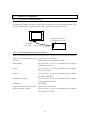
11-3-2 Using NSH-series PTs
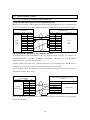
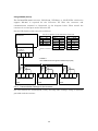
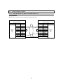
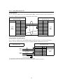
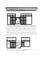
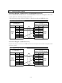
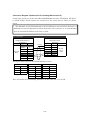
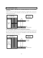
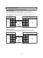
Connection Diagram 4
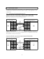
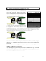
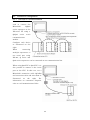
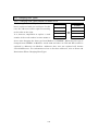
When connecting to the built-in PROGRAMMER of the CPU or SIO port
Connect the NSH cable (NSH5-232UL-[]M) to the 9-pin side of the Yokogawa CPU
port/D-sub 9-pin conversion cable (KM10-0C or KM10-0S), using a cable connected as
shown below.
To connect to the PROGRAMMER port, use KM10-0C. To connect to SIO
port, use KM10-0S.
DO NOT connect the CN7 and CN8 connectors of the NSH cable.
And, DO NOT
remove roopback connectors attatched to CN7 and CN8.
NSH Cable
( NSH5-232UL-□M)
Connector
D-Sub
9-pin
female
(mm screw:
female)
CPU port/D-Sub 9-pin Conversion Cable (9-pin side)
KM10-0C or KM10-0S (RS-232C, 9-pin)
Signal
Pin No.
Pin No.
FG
1
1
RD
2
2
SD
3
3
SD
CS
4
4
ER
RS
5
5
SG
+5V
SG
Signal
RD
6
6
DR
7
7
RS
8
8
CS
9
9
Connector Hood
Shield
Connector
D-Sub
9-pin
male
Connector Hood
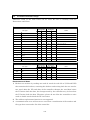
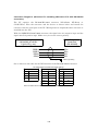
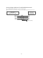
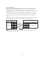
Connection Diagram 5
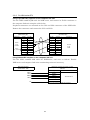
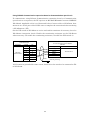
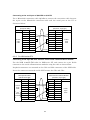
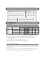
Connecting to 9-pin RS-232C connecter of the personal computer link module
Connect the D-Sub 9-pin connecter of the NSH cable (NSH5-232UL-[]M) to the personal
computer link module, using a cable below.
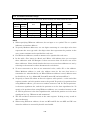
DO NOT connect the CN7 and CN8 connectors of the NSH cable.
And, DO NOT
remove roopback connectors attatched to CN7 and CN8.
NSH Cable
( NSH5-232UL-□M)
Connector
D-Sub
9-pin
female
(mm screw:
female)
FA-M3 Series Personal Computer Link Module
(RS-232C, 9-pin type)
Signal
Pin No.
Pin No.
FG
1
1
RD
2
2
RD
SD
3
3
SD
CS
4
4
ER
RS
5
5
SG
+5V
SG
Signal
6
6
DR
7
7
RS
8
8
CS
9
9
Connector Hood
Shield
142
Connector Hood
Connector
D-Sub
9-pin
male