1
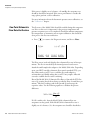
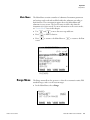
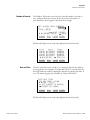
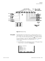
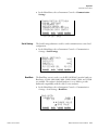
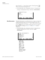
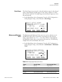
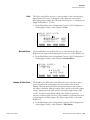
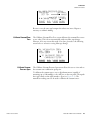
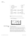
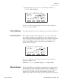
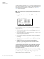
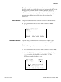
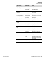
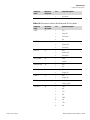
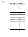
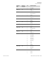
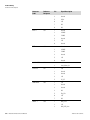
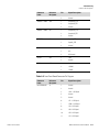
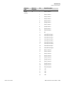
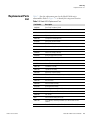
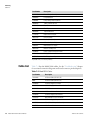
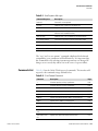
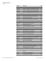
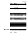
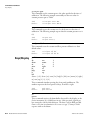
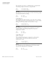
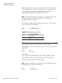
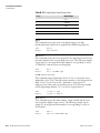
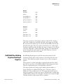
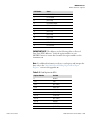
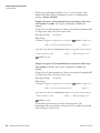
MODBUS Protocol
Function Codes
The outputs in the response message are packed as one per bit of the data
field. Status is indicated as 1 = Active (on) and 0 = Inactive (off). The LSB
of the first data byte contains the output addressed in the query. The other
outputs follow toward the high end of this byte, and from low order to
high order in subsequent bytes. If the returned output quantity is not a
multiple of eight, the remaining bits in the final data byte will be padded
with zeros (toward the high order end of the byte). The Byte Count field
specifies the quantity of complete bytes of data.
Note The values reported may not reflect the state of the actual relays in
the instrument, as the user may program these outputs for either active
closed or open. ▲
Request
Function Code
1 Byte
0x01 or 0x02
Starting Address
2 Bytes
0x0000 to maximum allowed by instrument
Quantity of Outputs
2 Bytes
1 to maximum allowed by instrument
Unit Identifier
1 Byte
0x00 to 0xFF (Passed back in response)
Function Code
1 Byte
0x01 or 0x02
Byte Count
1 Byte
N*
Output Status
N Byte
N = N or N+1
Response
*N = Quantity of Outputs / 8, if the remainder not equal to zero, then N=N+1
Error Response
Function Code
1 Byte
0x01 or 0x02
Exception Code
1 Byte
01=Illegal Function, 02=Illegal Address,
03=Illegal Data, 04=Slave Device Failure
Here is an example of a request and response to read outputs 2–15:
C-4
Model 5014i Beta Instruction Manual
Thermo Fisher Scientific