1
Introduction
Principle of Operation
A clean filter spot is introduced by an automatic filter change to the
combined sampling and detection chamber at least every 24 hours, usually
centered at midnight. However, the official filter tape change frequency for
TUV and U.S. EPA testing for both PM2.5 and PM10 is every 8 hours. The
automatic filter changes are controlled by the instrument firmware which
halts the pump operation, lowers the vacuum chamber plate, advances the
filter tape a fixed length, raises the vacuum chamber plate, and initiates the
pump operation and a zeroing of the sample spot. Immediately after a filter
change, a new measurement cycle is initiated with an automatic zero
adjustment of the mass signal. The filter change interval and time of day
can be user adjusted. Additionally, automatic filter changes will occur if the
mass on the filter exceeds 1,500 μg since the last filter change or if the flow
rate through the filter tape is reduced by more than 5% due to potentially
restrictive particle deposition.
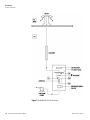
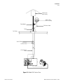
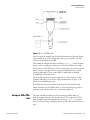
Using the example of PM10 monitoring, ambient air is drawn into a 10
micron (μm) size selective inlet which discriminates against particles with
an equivalent aerodynamic diameter above 10 μm. This inlet has been
approved previously through prior U.S. EPA designations (RFPS-0699130, 131, and 132) and is also listed within 40 CFR Part 50, Appendix L
as a 10-MICRON INLET (including model SA246b). The volumetric
flow rate at the inlet entrance is 16.67 liters per minute (1 m3/hour). In
addition, the ambient temperature and relative humidity is measured via a
naturally aspirated radiation shield and standard sensor as part of the
volumetric flow control and dynamic heating system.
Note Further particle discrimination would be achieved by inserting a
PM2.5 or PM1 cyclone between the 10-micron inlet and sample tube. TSP
inlets and European-style inlets are also available with the 5014i. ▲
The ambient particulate is then drawn down a vertically mounted heated
sample tube. The heat applied to the sampe is adjustable to either a fixed
temperature or a RH-threshold at the filter spot. The purpose of heating
the sample is to reduce particle bound water and to decrease the relative
humidity (RH) of the sample stream. This is done to reduce positive
artifact measurement that can potentially occur as a result of condensation
on the filter tape or conditions of elevated humidity. The heater is
controlled by the CPU and the power applied is proportional to the
conditions.
At the location where the sampling tube attaches to the Model 5014i
instrument case, a radial insulated tube joins the sampling tube to the
collection chamber. The particulate is drawn onto the glass fiber filter tape
between the proportional detector and the 14C beta source. Here, the beta
beam passes upwards through the filter tape and accumulated particulate
layer. The intensity of the beta beam is attenuated with the increasing mass
Thermo Fisher Scientific
Model 5014i Beta Instruction Manual
1-5