1
Installation
Connecting External Devices
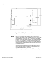
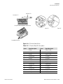
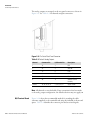
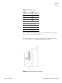
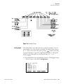
See Detail “A”
See Detail “B”
Component Side Viewed from Top of Board
Detail “A”
Detail “B”
Assembled Connector
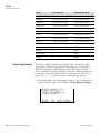
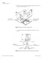
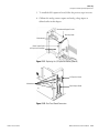
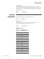
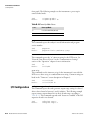
Figure 2–10. D/O Terminal Board Views
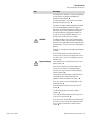
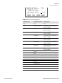
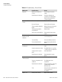
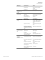
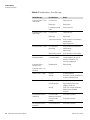
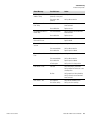
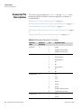
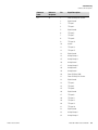
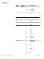
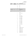
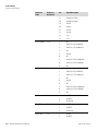
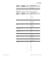
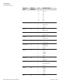
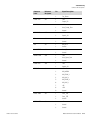
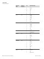
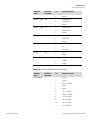
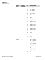
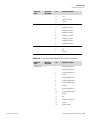
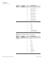
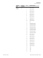
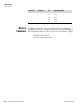
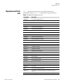
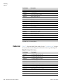
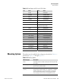
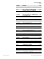
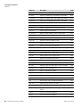
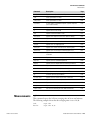
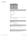
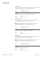
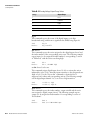
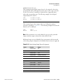
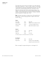
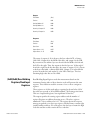
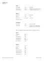
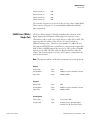
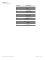
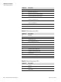
Table 2–4. D/O Terminal Board Pin Descriptions
25-Pin Terminal Board
Thermo Fisher Scientific
Screw
Signal Description
Screw
Signal Description
1
Relay1_ContactA
13
Relay7_ContactA
2
Relay1_ContactB
14
Relay7_ContactB
3
Relay2_ContactA
15
Relay8_ContactA
4
Relay2_ContactB
16
Relay8_ContactB
5
Relay3_ContactA
17
Relay9_ContactA
6
Relay3_ContactB
18
Relay9_ContactB
7
Relay4_ContactA
19
Relay10_ContactA
8
Relay4_ContactB
20
Relay10_ContactB
9
Relay5_ContactA
21
(not used)
10
Relay5_ContactB
22
+24V
11
Relay6_ContactA
23
(not used)
12
Relay6_ContactB
24
+24V
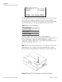
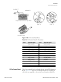
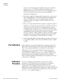
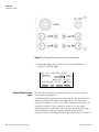
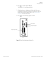
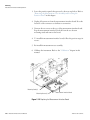
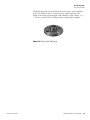
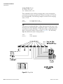
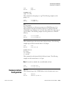
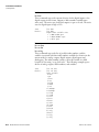
The 25-pin terminal board is included with the optional I/O Expansion
Board. Figure 2–11 shows the recommended method for attaching the
cable (customer supplied) to the terminal board using the included tie-
Model 5014i Beta Instruction Manual
2-19