1
Programmable Automation Controller
P E R F OR M A N CE
iQ Platform
16-4096
Q Series Automation Platform
QS Safety PLC
16-4096
12-1024
I/O
iQ Platform............................................................................................................................................................ 8
Q Series.............................................................................................................................................................. 14
MELSEC QS Safety............................................................................................................................................. 81
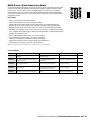
Stock Product: Stock product is product MEAU makes every effort to have on hand for immediate shipment. There may be instances when we are
out of stock due to unexpected large requirements. All stock product will be indicated in this book by an “S” in the Stocked Item columns/rows.
Non-Stock Product: Non-stock product is product supplied on an “as-needed” basis. Standard lead times of 12 - 16 weeks apply, product is
non-returnable and non-cancelable. Product listed as non-stock may change to stock product subject to increases in sales and usage. All nonstock product will be indicated in this book by a dash “-” in the Stocked Item columns/rows.
Mitsubishi Electric Automation
|
Programmable Automation Controller / PAC 7
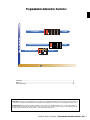
n PROGRAMMABLE AUTOMATION CONTROLLER / PAC
IQ Platform
iQ Platform
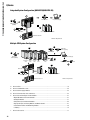
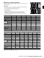
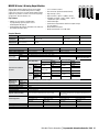
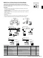
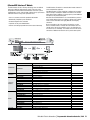
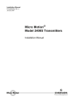
Multiple CPU System Configuration
D
A
Ethernet cable
(customer supplied)
*
RS-232 cable
USB cable
(customer supplied)
F
PC (GX Developer)
T
Battery for
QCPU (Q6BAT)
FRON
BAT
T
FRON
L
F
T
FRON
BAT
BAT
MPG
MPG
L
MPG
ACFAI
ACFAI
RIO
RIO
RIO
L
ACFAI
Memory card
Sequence
CPU
Motion
CPU
CNC
CPU
Robot
CPU
PC
CPU
PC card adapter
Memory card
F
Main base unit
B
*
E
C*
D
Extension cable
Power supply module
I/O, Intelligent function modules
Extension base unit
D
*Minimum Requirements
A. iQ CPUs....................................................................................................................................................... 10
B. iQ High Speed Base Units........................................................................................................................... 13
C. iQ Platform / Q Series Power Supply Modules............................................................................................ 25
Backward compatible with Q Series Power Supply Modules
D. iQ Platform / Q Series Extension Base Units and Connection Cables.......................................................... 25
8
Backward compatible with Q Series Extension Base Units and Cables
E.
iQ Platform / Q Series I/O and Intelligent Function Modules....................................................................... 27
Backward compatible with Q Series I/O and Intelligent Function Modules
• Digital I/O Modules and Terminal Blocks.................................................................................................. 27
• Analog I/O Modules.................................................................................................................................. 31
• Temperature Input and Control Modules.................................................................................................. 42
• High-Speed Input, Positioning Modules and Motion Control.................................................................... 47
• Serial Communication and Networking Modules...................................................................................... 56
• e-F@ctory................................................................................................................................................. 72
F.
iQ Platform / Q Series Accessories............................................................................................................. 77
Backward compatible with Q Series Accessories
The iQ Platform
• Selectable built-in Ethernet sequence CPUs, enabling program
upload/download, monitoring, debugging, SNTP, and FTP
functionality via Ethernet
• System configuration and PLC/Motion/HMI programming using
iQ Works
• Backward compatibility with Q Series programs and parameters
• Multiple program processing
• Selectable 8 or 32-axis high-speed fiber optic motion
controller CPUs
• Selectable 16-axis C70 CNC controller CPU
• Selectable vertical or horizontal type robot controller CPUs
• Infinite I/O and intelligent function module customization
possibilities
• Minimal hardware footprint
• Certified by UL, cUL, CE (as indicated), as well as DNV, ABS,
RINA, BV, LR and NK shipping approvals for all Q Series products
The iQ Platform unifies all of the Mitsubishi Electric automation
disciplines into a one-of-a-kind modular Programmable Automation
Controller (PAC). Based on the multi-CPU architecture of the
renowned Q Series Automation Platform, the iQ ultra high-speed
dual-bus back plane allows the iQ to be the only PAC to integrate
individual Sequence, Motion, CNC, and Robot control onto a single
rack. The iQ Platform is ideal for multi-discipline systems, requiring
at least one sequence CPU. Users can expand their configuration
with existing Q Series I/O and intelligent modules, providing
the iQ Platform customization flexibility without the cost of new
development or double-stock.
Key Features:
• Up to 4 CPUs total, including one sequence CPU; Motion, CNC,
and Robot CPUs available
• Large 4096 I/O capacity and as low as 9.5ns instruction
processing, with selectable CPU program size
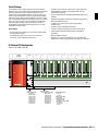
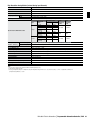
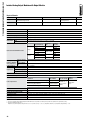
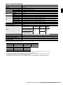
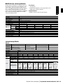
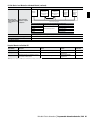
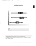
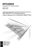
iQ Platform CPU Configuration
iQ Base Units: Q38DB or Q312DB
Power
Supply
CPU
0
1
2
3
4
5
6
7
Q03UDCPU
CON0
20
15
10
15
1
CON0
CON0
CON0
CON0
CON0
CON0
CON0
CON0
MODE
RUN
ERR.
30 USER
BAT.
25
BOOT
30
30
30
30
30
30
30
30
25
25
25
25
25
25
25
25
20
20
20
20
20
20
20
20
20
15
15
15
15
15
15
15
15
15
10
10
10
10
10
10
10
10
10
5
5
5
5
5
5
5
5
1
A
B
1
A
B
1
A
B
1
A
B
1
A
1
B
A
B
1
A
B
1
5
A
B
1
A
B
PULL
USB
RS-232
1st CPU
QnU Sequence CPU
Q03UD(E)CPU
Q04UD(E)HCPU
Q06UD(E)HCPU
Q10UD(E)HCPU
Q13UD(E)HCPU
Q20UD(E)HCPU
Q26UD(E)HCPU
Q50UDEHCPU
Q100UDEHCPU
2nd – 4th CPU
QnU Sequence CPU; 3 Max.
Q03UD(E)CPU
Q04UD(E)HCPU
Q06UD(E)HCPU
Q10UD(E)HCPU
Q13UD(E)HCPU
Q20UD(E)HCPU
Q26UD(E)HCPU
Q50UDEHCPU
Q100UDEHCPU
QD Motion CPU; 3 Max.
Q172DCPU
Q173DCPU
SQ Robot CPU; 3 Max.
Q172DRCPU
C70 CNC CPU; 2 Max.
Q173NCCPU-S01
C CPU, MES IT, or QPC; 3 Max.
Q12DCCPU-V
QJ71MES96IT
PPC-852
Mitsubishi Electric Automation
|
Programmable Automation Controller / PAC 9
n PROGRAMMABLE AUTOMATION CONTROLLER / PAC
A. iQ Platform CPUs
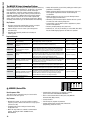
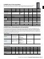
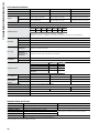
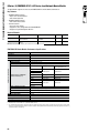
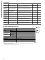
iQ Platform QnU “Universal” Sequence CPUs
• Vastly increased data storage and non-volatile program memory
• Utilizes dedicated high-speed CPU-only communication bus with
other iQ CPUs
• Backward compatibility with Q Series CPUs, I/O and Intelligent
Modules; QnU CPUs can be configured in single-CPU and / or
standard Q Series CPUs
• Built-in Ethernet port for increased accessibility and ease-of-use
• USB (Mini-B) connection to CPU for rapid program
upload/download
The QnU CPUs bring high-end sequence control to the Mitsubishi
PAC lineup and are required in every iQ system. These CPUs are most
effective when used in conjunction with other iQ Platform CPUs such
as Motion, Robot, CNC, PC and C Language controllers. However, they
can also be used in Q Series configurations to increase performance
and functionality.
Key Features:
• World-leading processor execution speeds as low as 9.5ns
per instruction
• Significantly enhanced arithmetic and data processing (sorting,
floating point, etc.)
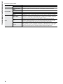
Required Manuals
Model Number
Description
Included with CPU?
Stocked Item
SH(NA)080483
QCPU Users Manual
No
-
SH(NA)080485-ENG
QCPU Users Manual (Multiple CPU Systems)
No
-
SH(NA)080807-ENG
QnUCPU Users Manual
No
-
SH(NA)080809-ENG
QCPU Programming
No
-
SH(NA)080811-ENG
QnUCPU Users Manual (Ethernet Communication)
No
-
Note: Many of these manuals are available by free download from our website, www.meau.com
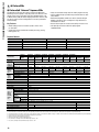
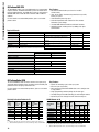
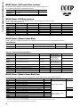
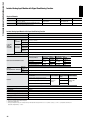
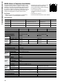
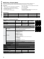
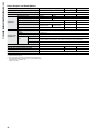
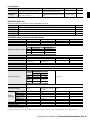
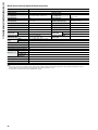
Model Number
Standard
Built-In
Ethernet
Stocked Item
Processing LD X0
Speed
(Sequence
MOV D0 D1
Instruction)
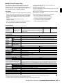
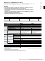
Q04UDHCPU Q06UDHCPU Q10UDHCPU Q13UDHCPU Q20UDHCPU Q26UDHCPU Q04UDEHCPU
Q06UDEHCPU
Q10UDEHCPU
Q13UDEHCPU
Q20UDEHCPU
Q26UDEHCPU
Q50UDEHCPU
Q100UDEHCPU
S
-
S
-
S
-
-
1000k steps
S
S
20ns
9.5ns
40ns
19ns
30k steps
40k steps
60k steps
100k steps
130k steps
200k steps
260k steps
500k steps
Program Memory (Drive 0)
120k bytes
160k bytes
240k bytes
400k bytes
520k bytes
800k bytes
1040k bytes
2000k bytes
4000k bytes
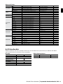
Standard RAM (Drive 3)
Standard ROM (Drive 4)
Program Memory
Standard RAM
192k bytes
1024k bytes
124
4 files
256k bytes
768k bytes
1024k bytes
2048k bytes
252 (*3)
1536k bytes
8192k bytes
1792k bytes
16384k bytes
Program Capacity (*1, *2)
Memory
Capacity
(*1)
Q03UDCPU
Q03UDECPU
Max.
Number
of Files
Standard ROM
Stored
Memory Card Interface
Yes
Max. I/O Device Points
Max. Physical I/O Points
No. of Device Points
File Registers
8192 points (X/Y0 to 1FFF)
4096 points (X/Y0 to FFF)
Set in PLC parameters
Available
Specs. of
Built-In
Ethernet
Port CPU
Module
(*4)
1280k bytes
4096k bytes
256
512
Data Transmission Speed
100/10Mbps
Communication Mode
Full-duplex / Half duplex
Ethernet Functions
Max. Distance Between Hub
and Node
Max. No. of 10BASE-T
Connectable
100BASE-TX
Nodes
Program upload/download, remote monitor/maintenance, HMI connection, FTP server, SNTP
Number of Connections (*5)
16 for MELSOFT connection and MC protocol, 1 for FTP
100m (328.08 feet)
Cascade connection: Four stages maximum
Cascade connection: Two stages maximum
Communication Ports
USB (Mini-B), RS-232 / Ethernet
USB (Mini-B), Ethernet
5VDC Internal Current Consumption
0.33A (*6)
0.50A
Base Unit Slots Occupied
1
Weight (kg)
0.20 (0.22 for CPUs with built-in Ethernet ports)
0.39A (*7)
0.24
Notes:
1. The unit of the file size stored in the memory area varies depending on the CPU module. For more details, refer to the QCPU User’s Manual (Function Explanation, Program Fundamentals)
2. The maximum number of executable sequence steps is shown. (Program capacity) - (File header size (default: 34 steps)). For details, refer to the QCPU User’s Manual (Function Explanation, Program Fundamentals).
3. The CPU module can only execute up to 124 programs, though more may be stored.
4. Applies to QnU CPUs with built-in Ethernet ports only.
5. Indicates the total number of TCP/IP and UDP/IP protocols.
6. The current value consumption of the built-in Ethernet part version is 0.46A
7. The current consumption of the built-in Ethernet port version is 0.46A.
10
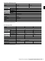
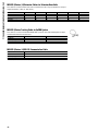
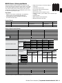
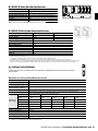
iQ Platform Motion CPUs
Key Features:
The iQ Platform unifies four key fields of automation, one being
servo motion. The iQ Motion CPUs combined with MR-J3 servos
deliver the highest level of speed and precision with tight integration
to interdisciplinary automation control. Exploiting the high-speed
inter-CPU communication bus, servo movement can be scattered
seamlessly throughout Sequence, Robot, and CNC operations.
• Accelerated communication speed over a freely designated
expanded range of inter-CPU shared memory
• Additional clutch control functionality
• Faster processing for improved multi-axis support
• Up to 32 axes per CPU, 96 axes per system
• MR-J3-B Servo and SSCNETIII benefits, including noise free,
50Mbps, fiber optic communication, and active auto-tuning
For more details on associated Motion products, please see the
Motion Controllers product section.
Required Manuals
Model Number
Description
Included with CPU?
Stocked Item
IB(NA)0300133-A
QD Users Manual
No
S
IB(NA)0300134-A
QD Common Manual
No
S
IB(NA)0300136-A
QD Real Mode Manual
No
S
IB(NA)0300137-A
QD Virtual Mode Manual
No
S
IB(NA)0300135-A
QD SFC Programming Manual
No
S
Note: Many of these manuals are available by free download from our website, www.meau.com
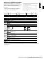
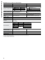
Model Number
Stocked Item
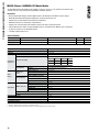
Q173DCPU
S
Q172DCPU
S
Number of Control Axes
Up to 32 axes
Up to 8 axes
SV13
0.44ms / 1 to 6 axes; 0.88ms / 7 to 18 axes
1.77ms / 19 to 32 axes
0.44ms / 1 to 6 axes; 0.88ms / 7 to 8 axes
SV22
0.44ms / 1 to 4 axes; 0.88ms / 5 to 12 axes
1.77ms / 13 to 28 axes; 3.55ms / 29 to 32 axes
0.44ms / 1 to 4 axes; 0.88ms / 5 to 8 axes
Operation Cycle (Default)
Manual Pulse Generator Operation
Possible to connect 3 modules
Function
Synchronous Encoder Operation Function 12 modules max.
Number of SSCNET III Systems (*1)
2 systems
8 modules max.
1 system
Motion Related Interface Module
Q172DLX: 4 modules usable; Q172DEX: 6 modules usable
Q173DPX: 4 modules usable (*2)
Q172DLX: 1 module usable; Q172DEX: 4 modules usable
Q173DPX: 3 modules usable (*2)
Internal Current Consumption (5VDC) [A]
1.25
1.14
Mass (kg)
Base Unit Slots Occupied
0.33
1
0.33
Notes:
1. The servo amplifiers for SSCNET cannot be used.
2. When using the incremental synchronous encoder (SV22 use), you can use above number of modules. When connecting the manual pulse generator, you can use only 1 module.
Synchronous Encoder
Type
Model Number
Stocked Item
Q173DCPU
Q172DCPU
Base Unit Slots Occupied
Synchronous Encoder
Serial Absolute
Q172DEX
S
12 modules
8 modules
1
Manual Pulse Generator
Incremental
Q173DPX
S
12 modules
8 modules
Mitsubishi Electric Automation
3 modules
3 modules
|
Programmable Automation Controller / PAC 11
n PROGRAMMABLE AUTOMATION CONTROLLER / PAC
iQ Platform CNC CPU
The Q173NCCPU enables entry level CNC Control to be integrated with
Sequence, Motion, and Robot automation systems. Also known as the
C70 Series CNC Controller, an iQ CNC CPU system uses multi-purpose
GOT1000 HMIs and on-rack I/O cards to minimize TCO on CNC line
solutions.
For more details on associated CNC products, please see the CNC
product section.
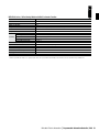
Required Manuals
Model Number
IB1500261
IB1500267
Key Features:
• Accelerated communication speed over the inter-CPU
shared memory
• Up to 16 axes with 4 simultaneously controlled axes per CPU,
2 CPUs per system
• 16.8k Block/min processing speed
• Streamlined production with reduced Tact Time and host
information system linkage
• Uses GOT1000 HMI and iQ rack-based I/O card interfaces
• SSCNETIII benefits, including noise free, 50Mbps, fiber optic
communication
Description
C70 Connection Manual
C70 Instruction Manual
Contents
Covers Q173NCCPU installation and connections
Covers screen operation for C70
Describes the various signal interfaces and functions
C70 PLC Interface Manual
required when creating sequence program of PLC CPU to
operate C70
C70 Programming Manual (Machining Center System) Covers programming for machining centers
C70 Programming Manual (Lathe System)
Covers programming for lathe systems
C70 Setup Manual
Covers setup
C70 CPU Module Q173NCCPU Specifications Manual General and functional specifications
IB1500263
IB1500269
IB1500275
IB1500265
IB1500259
Included with CPU?
Yes (PDF format)
Yes (PDF format)
Stocked Item
-
Yes (PDF format)
-
Yes (PDF format)
Yes (PDF format)
Yes (PDF format)
Yes (PDF format)
-
Note: Many of these manuals are available by free download from our website, www.meau.com
CNC CPU Specifications
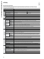
Q173NCCPU-S01
Machining Center Type
Lathe Type
Stocked Item
S
S
Number of Control Axes
16
Maximum Number of Simultaneous Control Axes
4
Maximum Number of Spindles
7
Maximum Number of PLC Axes
7
Maximum Number of Phase Systems
7
Control Unit
1µm / 0.1µm
Interpolation Processing Performance
16.8k Block/min
Max Feed Rate
1000m/min
Base Unit Slots Occupied
1
4
3
Note: If used, the Q173SXY CNC Safety I/O module requires programming by GX Developer (unavailable with GX Works2)
iQ Platform Robot CPU
The new Q172DRCPU Robot controller combines faster processing
speed and enhanced motion control, providing superior flexibility and
performance when designing robotic work cells.
For more details on associated Robot products, please see the Robot
product section.
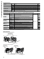
Vertically Articulated Robots for iQ
• Capable of controlling up to 3 robots per system
• Base Unit (one slot per CPU)
• Both vertically articulated and SCARA robots can be configured on
a single platform
• Single programming software package for all robot types
• Versatility through shared iQ networking, I/O, and intelligent modules
• Improved cycle times through inter-CPU shared memory bus
SCARA Robots for iQ
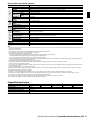
Model
Number
(*1, *2)
Axes /
Degrees of
Freedom
Max.
Payload
(kg)
RV-2SQ-_
6
2
Max.
Reach
Radius
(mm)
504
± .02
-
RV-3SQJ-_
5
3.5
641
± .02
-
RV-3SQ-_
6
3.5
642
± .02
-
RV-6SQ-_
6
6
695
± .02
-
RV-6SQL-_
6
6
902
± .02
-
RV-12SQ-_
6
12
1086
± .05
-
RV-12SQL-_
6
12
1385
± .05
-
Position
Stocked
Repeatability
Item
(mm)
Notes:
1. Includes arm, drive unit, CPU, arm to drive unit cable set, and CPU to drive unit cable set.
2. -_ Indicates additional specifications for UL, clean, and oil mist types. Please consult with MEAU.
12
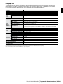
Key Features:
Model Number
(*1, *2)
Axes /
Max.
Degrees
Payload
of
(kg)
Freedom
Max.
Z Axis
Reach
Stroke
Radius
(mm)
(mm)
Position Repeatability
X-Y
Z
J4
Composite
(mm) (deg.)
(mm)
Stk
Item
RH-3SQHR3515-_ 4
3
350
150
± .01
± .01
± .01
-
RH-6SQH3520-_
4
6
350
200
± .02
± .01
± .02
-
RH-6SQH4520-_
4
6
450
200
± .02
± .01
± .02
-
RH-6SQH5520-_
4
6
550
200
± .02
± .01
± .02
-
RH-12SQH5535-_ 4
12
550
350
± .02
± .01
± .03
-
RH-12SQH7035-_ 4
12
700
350
± .025
± .01
± .03
-
RH-12SQH8535-_ 4
12
850
350
± .025
± .01
± .03
-
RH-18SQH8535-_ 4
18
850
350
± .025
± .01
± .03
-
Notes:
1. Includes arm, drive unit, CPU, arm to drive unit cable set, and CPU to drive unit cable set.
2. -_ Indicates additional specifications for UL, clean, and oil mist types. Please consult with MEAU
Options for iQ Robots
Model Number
R32TB
R32TB-15
Teach Pendants
R56TB
R56TB-15
RT-TOOLBOX 2 C1
RT-TOOLBOX 2 LT-C1
Software
MELFA-VISION-C1
MELFA-WORKS-C1
2A-RZ365
Hand Interface Card
2A-RZ375
1E-VD01
1E-VD01E
1E-VD02
1E-VD02E
1S-VD0_-02
1S-VD0_E-02
Solenoid Valve
Sets*
1S-VD0_-01
1S-VD0_E-01
1S-VD0_M-04
1S-VD0_ME-04
1S-VD0_M-03
1S-VD0_ME-03
1E-GR35S
1S-HC30C-11
1S-GR35S-01
Hand I/O Cables
1S-HC25C-01
1S-GR35S-02
1S-HC35C-02
1N-ST0602C
1N-ST0604C
1N-ST0606C
1N-ST0608C
1E-ST0402C
Hand Curl Tube
1E-ST0404C
1E-ST0406C
1E-ST0408C
1E-ST0408C-300
Description
Standard Teach Pendant, 7m Cable
Standard Teach Pendant 15m Cable
Enhanced Teach Pendant 7m Cable
Enhanced Teach Pendant 15m Cable
Robot Programming and Setup SW-Light Version
Robot Programming and Setup SW
Vision Interface and Setup SW Tool
Advanced Design and Integration SW Tool
Pneumatic Hand Interface
Pneumatic Hand Interface
1 Valve Set with Connection Cable (Sink)
1 Valve Set with Connection Cable (Source)
2 Valve Set with Connection Cable (Sink)
2 Valve Set with Connection Cable (Source)
Valve Set with Connection Cable (Sink)
Valve Set with Connection Cable (Source)
Valve Set with Connection Cable (Sink)
Valve Set with Connection Cable (Source)
Valve Set with Connection Cable (Sink)
Valve Set with Connection Cable (Source)
Valve Set with Connection Cable (Sink)
Valve Set with Connection Cable (Source)
Hand Output Cable
Hand Input Cable
Hand Output Cable
Hand Input Cable
Hand Output Cable
Hand Input Cable
Φ6 - 1 Connection
Φ6 - 2 Connections
Φ6 - 3 Connections
Φ6 - 4 Connections
Φ4 - 1 Connection
Φ4 - 2 Connections
Φ4 - 3 Connections
Φ4 - 4 Connections
Φ4 - 4 Connections, 300 mm
Notes
Basic Teaching and Operation
Basic Teaching and Operation
Advanced Function Pendant
Advanced Function Pendant
Without Simulation Tool
With Simulation Tool
Compatible with Cognex “In-Sight” sensors
Add on to Solid Works Required
Sink Type
Source Type
RV-2
RV-2
RV-2
RV-2
RV-3, 6
RV-3, 6
RV-12
RV-12
RH-6
RH-6
RH-12, 20
RH-12, 20
8-Connection, RV-2
12-Connection, RV-2
4-Connection, RV-3, 6, 12
8-Connection, RV-3, 6, 12
4-Connection, RH
8-Connection, RH
RV-12
RV-12
RV-12
RV-12, RH-6, 12, 20
RV-2, 3, 6
RV-2, 3
RV-3, 6
RV-3, 6
RH-6
Stocked Item
S
S
S
S
S
S
S
S
S
S
S
S
S
S
S
S
S
S
S
S
S
S
S
S
S
S
S
S
S
S
S
S
S
S
*Note 1: _ = number of valves (1-4)
B. iQ Platform Base Units
The high speed iQ base units utilize a secondary inter-CPU bus to share more data at faster speeds between up to 4 iQ CPUs. Non-iQ CPUs
may be used on the base unit, but will not increase in performance.
Base Units
Model Number
Stocked Item
Certification
Expansion Slots
(Excluding 1st CPU Slot)
Applicable I/O and Intelligent
Function Modules
Dimension (W x H) mm (in)
Weight (kg)
Accessories
DIN Rail Mounting Adapters
Q38DB
S
UL • cUL • CE
Q312DB
S
8
12
Model Number
Applicable Base or Extension Base
Stocked Item
Q6DIN1
Q38DB, Q312DB
S
Q Series/iQ modules
328 x 98 (12.92 x 3.86) 439 x 98 (17.30 x 3.86)
0.41
0.54
4- M4 x 14 base unit mounting screws
Mitsubishi Electric Automation
|
Programmable Automation Controller / PAC 13
n PROGRAMMABLE AUTOMATION CONTROLLER / PAC
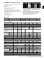
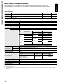
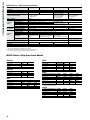
Q Series Automation Platform
Q Series
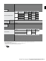
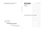
Integrated System Configuration (Q00UJCPU/Q00UJCPU-S8)
D
A*
F
PC (GX Developer)
RS-232 cable
F
Battery for QCPU
(Q6BAT)
E
D
Extension cable
I/O, Intelligent function modules
Extension base unit
D
* Minimum Requirements
Multiple CPU System Configuration
D
A*
USB cable
(customer supplied)
RS-232 cable
F
Battery for
QCPU (Q6BAT)
PC (GX Developer)
F
Sequence
CPU
*
C
Motion
CPU
Process
CPU
PC
CPU
Redundant
CPU
B*
Memory card
E
PC card adapter
Memory card
F
Main base unit
D
Extension cable
C
Power supply module
Extension base unit
I/O, Intelligent function modules
* Minimum Requirements
A. Q Series CPUs............................................................................................................................................. 16
B. Q Series Standard Base Units..................................................................................................................... 24
C. Q Series Power Supply Modules................................................................................................................. 25
D. Q Series Extension Base Units and Cables.................................................................................................. 25
14
E.
Q Series I/O and Intelligent Function Modules............................................................................................ 27
• Digital I/O Modules and Terminal Blocks.................................................................................................. 27
• Analog I/O Modules.................................................................................................................................. 31
• Temperature Input and Control Modules.................................................................................................. 42
• High-Speed Input, Positioning Modules and Motion Control.................................................................... 47
• Serial Communication and Networking Modules...................................................................................... 56
• e-F@ctory................................................................................................................................................. 72
F.
Q Series Accessories.................................................................................................................................. 77
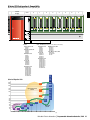
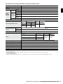
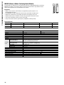
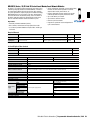
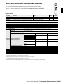
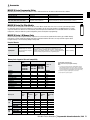
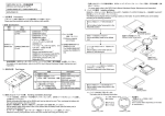
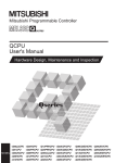
Q Series CPU Configuration & Compatibility
Q Series Standard and Slim-type Base Units: Q_B and Q_SB
Power
Supply
CPU
Q03UDCPU
0
CON0
1
CON0
2
CON0
3
CON0
4
CON0
5
CON0
6
CON0
7
CON0
CON0
15
MODE
RUN
30 ERR.
USER
25 BAT.
BOOT
20
20
20
20
20
20
20
20
20
10
15
15
15
15
15
15
15
15
15
10
10
10
10
10
10
10
10
10
5
5
5
5
5
5
5
5
20
15
1
1
A
30
30
30
30
30
30
30
30
25
25
25
25
25
25
25
25
1
B
A
1
B
A
B
1
A
1
B
A
1
B
A
B
1
A
B
1
5
A
B
1
A
B
PULL
USB
RS-232
1st CPU
2nd – 4th CPU (Dependent on 1st CPU and Base Unit Selected)
QnH Sequence CPU
Q02CPU
Q02HCPU
Q06HCPU
Q12HCPU
Q25HCPU
Process CPU
Q02PHCPU
Q06PHCPU
Q12PHCPU
Q25PHCPU
QnU Sequence CPU
Q03UD(E)CPU
Q04UD(E)HCPU
Q06UD(E)HCPU
Q10UD(E)HCPU
Q13UD(E)HCPU
Q20UD(E)HCPU
Q26UD(E)HCPU
Q50UDEHCPU
Q100UDEHCPU
Basic Q Sequence CPU
Q00CPU
Q01CPU
Basic QnU Sequence CPU
Q00UCPU
Q01UCPU
Q02UCPU
QnH Sequence CPU
Q02CPU
Q02HCPU
Q06HCPU
Q12HCPU
Q25HCPU
Process CPU
Q02PHCPU
Q06PHCPU
Q12PHCPU
Q25PHCPU
QnU Sequence CPU
Q03UD(E)CPU
Q04UD(E)HCPU
Q06UD(E)HCPU
Q10UD(E)HCPU
Q13UD(E)HCPU
Q20UD(E)HCPU
Q26UD(E)HCPU
Q50UDEHCPU
Q100UDEHCPU
Q100
UDEH
Q Series Migration Path
Q50
UDEH
260K
252K
Q26
UD(E)H
Q25H
Q20
UD(E)H
200K
High Performance
Model
130K
124K
Q13
UD(E)H
Q12H
Q10
UD(E)H
100K
60K
Q06
UD(E)H
Q06H
40K
30K
28K
Q02
Q02H
20K
15K
14K
10K
8K
Q/QH Motion CPU; 3 Max.
Q172HCPU
Q173HCPU
Q172CPUN
Q173CPUN
C CPU, MES IT, or QPC; 3 Max.
Q12DCCPU-V
QJ71MES96IT
PPC-852
Q03
UD(E)
Q04
UD(E)H
Q02U
Basic Model
Q00J
Q00
200
160
Q01U
Q01
Q00UJ
120
Universal
Model
Q00U
100
80 79
60
40
34
20
9.5
(ns)
Mitsubishi Electric Automation
|
Programmable Automation Controller / PAC 15
n PROGRAMMABLE AUTOMATION CONTROLLER / PAC
The MELSEC Q Series Automation Platform
Q Series PACs are multi-disciplinary automation platforms addressing
the needs of both OEMs and end users. The Q Series is the original
multi-CPU system, with up to 4 CPUs to divide-and-conquer
larger applications. It provides scalable automation solutions to
both small and very large systems, offering a broad spectrum of
automation capabilities. Additional CPUs and intelligent function
module expansions allow the Q series to handle sophisticated
motion, process control, PC and C language based control, MES IT
interfacing, and numerous types of communication and networking.
Key Features:
• CPU types ranging from small/medium systems, to complex
networked systems with tens of thousands of I/O
• Reduced lifecycle costs via remote system management
and maintenance
• Redundant CPU capability available for hot-backup of
critical systems
• Multiple CPU capability (up to 4 CPUs) adding open ended system
performance and flexibility
• Multiple programs allowing concurrent development, code reuse,
better program organization and faster troubleshooting for
less downtime
• Multiple simultaneous access to the system allowing for faster
system debugging and maintenance
• Networking & communication options distribute Q Series systems
over wide areas while reducing wiring costs
• Sequence CPUs can also address process applications by means
of built-in PID capabilities
• Extremely compact package saves panel costs
• Certified by UL, cUL, CE (as indicated), as well as DNV, ABS, RINA,
BV, LR and NK shipping approvals for all Q Series products
Required Manuals
Model Number
Description
QCPU(Q mode) CPU Module User’s
Manual (Hardware)
Contents
General specs, CE compliance information, Installation, safety requirements,
Power supply wiring, overview of system parts
Included with CPU?
No (included with base
units)
Stk Item
SH(NA)080483
Q CPU (Q Mode) User’s Manual
(Hardware Design, Maintenance &
Inspection)
CPU H/W specs, PSU spec, Base Unit specs, CE compliance information,
Maintenance & inspection, Installation, Troubleshooting
No (purchase separately)
-
SH(NA)080484
QCPU(Q Mode) User’s Manual
(Function Explanation, Program
Fundamentals)
CPU specifications, system configuration, programming basics, I/O assignments,
memory organization, CPU functions, communication with intelligent function
modules, parameters & devices, program up/downloads, overview of multiple
program architecture, programming basics, overview of multiple CPU system
No (purchase separately)
-
SH(NA)080485
QCPU User’s Manual (Multiple CPU
System)
Outline, system configuration, concept for multiple CPU system,
communication between CPU modules, processing time of QCPU in multiple
CPU system, parameter added for multiple CPU system, precautions for use
of AnS Series module, starting up the multiple CPU system
No (purchase separately)
-
SH(NA)080039
QCPU(Q Mode)/QnACPU Programming
Manual (Common Instructions)
General Description, Instruction Tables, Configuration of Instructions, How
To Read Instructions, Sequence Instructions, Basic Instructions, Application
Instructions, Instructions For Data Link, QCPU Instructions, Redundant
System Instructions, Error Codes
No (purchase separately)
-
SH(NA)080041
QCPU(Q Mode)/QnACPU Programming
Manual (SFC)
General Description, System Configuration, Specifications, SFC Program
Configuration, SFC Program Processing Sequence, SFC Program Execution
No (purchase separately)
-
SH(NA)080076
Q CPU (Q Mode) Programming Manual General Description, System Configuration, Specifications, SFC Program
(MELSAP-L)
Configuration, SFC Program Processing Sequence, SFC Program Execution
IB(NA)0800061
SH(NA)080040
QCPU(Q Mode)/QnACPU Programming
Manual (PID Control Instructions)
General Description, System Configuration for PID Control, PID Control
Specifications, Functions of PID Control, PID Control Procedure, PID Control
Instructions, How To Read Explanations For Instructions, Incomplete
Derivative PID Control Instructions and Program Examples, Complete
Derivative PID Control Instructions and Program Examples
SH(NA)080366
Programming Guide Book for
Structured Text (ST)
Covers Structured Text programming method
No (purchase separately)
-
No (purchase separately)
-
No (purchase separately)
-
Note: Many of these manuals are available by free download from our website, www.meau.com
Q00JCPU
POWER
RUN
ERR.
PULL
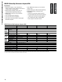
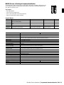
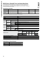
A. MELSEC Q Series CPUs
Basic Sequence CPUs
These CPUs offer an economical entry-level version of the
Q Series for small scale systems.
Key Features:
• Multiple CPU support; use up to three CPUs to combine
sequence, process, motion & PC control on a single system
(Version B or later)
• Compatible with Q Series Intelligent Function Utility
configuration tools
• Offers full range of Q Series network & communication
features, including CC-Link IE 100Mbit Ethernet,
MELSECNET/H
16
-
PULL
RS-232
• Integrated PSU, CPU and base unit available to simplify
system construction with Q00UJCPU/Q00JCPUs
• Built in serial communications via CPU port (using MELSEC
Communication (MC) protocol)
• Security functions
• Flash memory for programs & parameters
• Supports floating point, function block, PID and SFC
programming (Version B or later)
Integrated Basic Q/QnU Sequence CPUs
Model Number
Q00UJCPU
Q00UJCPU-S8
Stocked Item
Certification
S
UL • cUL • CE
S
UL • cUL • CE
Combined QnU CPU, PSU and 5-Slot Base Unit
Combined QnU CPU, PSU and 8-Slot Base Unit
Hardware Format
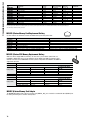
Processing Speed
(Sequence Instruct)
Program Capacity (*1)
Memory Capacity
Max. Number of Files
Stored
Memory Card Interface
Max. I/O Device Points
Max. Physical I/O Points
LD X0
MOV (MOV D0 D1)
120ns
240ns
10k steps
Program Memory (Drive 0) 40 kbytes
Standard RAM (Drive 3)
0
Standard ROM (Drive 4)
256 kbytes
Program Memory
32
Standard ROM
128
No
8192 points (X/Y0 to 1FFF)
256 points (X/Y0 to FF)
Number of Device Points
Set in PLC parameters
File Registers
Permissible Instantaneous Power Failure Time
Not available
20ms
Communication Ports
5VDC Internal Current Consumption (A)
Weight (kg)
Base Unit Slots Occupied
USB (Mini-B) RS-232
0.37
0.70
CPU integrated into base unit
Note:
1. Maximum actual program size is program capacity-34 steps.
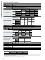
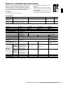
Basic QnU Sequence CPUs
Model Number
Q00UCPU
Q01UCPU
Q02UCPU
Stocked Item
S
S
S
Certification
UL • cUL • CE
Hardware Format
Processing Speed
(Sequence Instruct)
Program Capacity (*1)
Memory Capacity
Max. Number of Files
Stored
CPU only
LD X0
80ns
60ns
40ns
MOV (MOV D0 D1)
160ns
120ns
80ns
10k steps
Program Memory (Drive 0) 40 kbyte
128 kbyte
Standard RAM (Drive 3)
15k steps
20k steps
60 kbyte
80 kbyte
Standard ROM (Drive 4)
512 kbyte
512 kbyte
512 kbyte
Program Memory
32
32
32
Standard ROM
256
256
Memory Card Interface
256
No
Yes
Max. I/O Device Points
8192 points (X/Y0 to 1FFF)
Max. Physical I/O Points
1024 points (X/Y0 to 3FF) (*2)
Number of Device Points
Set in PLC parameters
File Registers
Available
8192 points (X/Y0 to 1FFF)
2048 points (X/Y0 to 7FF) (*2)
Communication Ports
USB (Mini-B) RS-232
USB (Mini-B) RS-232
5VDC Internal Current Consumption (A)
0.33
0.33
0.23
Weight (kg)
0.15
0.15
0.20
Base Unit Slots Occupied
1
1
1
Notes:
1. Maximum actual program size is (program capacity-34 steps).
2. Number of I/O points on the main/extension base directly controlled by the CPU module.
Mitsubishi Electric Automation
|
Programmable Automation Controller / PAC 17
n PROGRAMMABLE AUTOMATION CONTROLLER / PAC
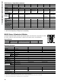
MELSEC Q Series High Performance Sequence CPUs
Q02CPU
Key Features
• Multiple CPU support; use up to four CPUs to
combine sequence, process, motion & PC control on
a single system in any combination
• Multiple program capability; allows up to 124
separate programs, depending on CPU type
• Multiple access to CPUs by several technicians
simultaneously
• Very broad range of CPU capabilities
• Very high speed processing capability
• USB (Type B) connection to CPU for rapid upload/
download of programs
• Up to 32MB of data storage by use of removable
memory cards
• Supports floating point, PID and SFC programming
• Increased functionality in Version B or later
(S/N 07032x)
• SFC active step comment readout instruction
• Increased multiple CPU shared memory flexibility
• 1/1000 second resolution timestamp capability
• Store sampling trace data in Standard RAM
• Power supply error detection function
USB
RS-232
Model Number
Q02HCPU
Q06HCPU
Q12HCPU
Q25HCPU
Stocked Item
Certification
S
UL • cUL • CE
S
UL • cUL • CE
S
UL • cUL • CE
UL • cUL • CE
Processing LD (LD X10)
Speed
(Sequence
MOV (MOV D0 D1)
Instruc.)
34ns
Program Memory (Drive 0) 28k steps
60k steps
124k steps
252k steps
Program Memory (Drive 0)
Standard RAM (Drive 3)
Standard ROM (Drive 4)
CPU Shared Memory
Program Memory
Standard RAM
112 kbytes
128 kbyte
112 kbyte
8 kbyte (not latched)
28
3
240 kbytes
128 kbyte
240 kbyte
496 kbytes
256 kbyte
496 kbyte
1008 kbytes
256 kbyte
1008 kbyte
60
124
252
28
60
124
252
0.64
0.20
0.64
0.20
0.64
0.20
Memory
Capacity
Max.
Number
of Files
Standard ROM
Stored
Memory Card Interface
Max. I/O Device Points
Max. Physical I/O Points
Number of Device Points
File Registers
Communication Ports
5VDC Internal Current Consumption (A)
Weight (kg)
Base Unit Slots Occupied
102ns
Yes
8192 points (X/Y0 to 1FFF) (*1)
4096 points (X/Y0 to FFF) (*2)
Set in PLC parameters
Available
USB (Type B), RS-232
0.64
0.20
1
Notes:
1. Sum of the number of I/O points on the main/extension base directly controlled by the CPU module and the number of I/O points controlled as remote I/O by the remote I/O network.
2. Number of I/O points on the main/extension base directly controlled by the CPU module.
18
MODE
RUN
ERR
USER
BAT
BOOT
PULL
PULL
MELSEC Q Series High Performance Sequence CPUs
Program
Capacity
Q02HCPU
MODE
RUN
ERR
USER
BAT
BOOT
RS-232
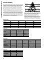
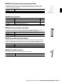
MELSEC QH Motion CPUs
Key Features:
QH Motion CPUs offer the ability to integrate complex
motion systems on a Q Series system alongside sequence,
process & PC based functions. The motion CPUs allow
costly, inflexible mechanical systems to be replaced by
multiple axis motion control that is significantly easier and
less expensive to design, build and re-configure. QH Motion
uses the fiber optic SSCNET III Servo System control
network and MR-J3B type amplifiers.
• Up to 32 axes controlled by one CPU, allowing up to 96
axes per base rack
• Servo axes connect quickly and easily via daisy chain
connection on SSCNET, eliminating complex, expensive
wiring harnesses
• SSCNET offers high speed, deterministic control of each
axis independently
• Allows integration with other automation technologies
such as open language program control and Ethernet/
Internet capabilities
Required Manuals
Q172HCPU
MODE
RUN
ERR.
M.RUN
BAT.
BOOT
FRONT
SSCNETIII
BAT
CN1
PC
TU
PULL
USB
Model Number
Description
Contents
Included with CPU?
Stk Item
IB(NA)0300040
Q172CPU(N)/Q173CPU(N) User’s Manual
Covers the Q172CPUN and Q173CPUN
No (purchase separately)
-
Note: Many of these manuals are available by free download from our website, www.meau.com
MELSEC QH Series Motion Controller CPU Modules
Model Number
Q172HCPU
Q173HCPU
Stocked Item
S
S
Certification
UL • cUL • CE
Number of Control Axes
8 axes
32 axes
SV13
0.44ms / 1 to 3 axes
0.88ms / 4 to 8 axes
0.44ms / 1 to 3 axes
0.88ms / 4 to 10 axes
1.77ms / 11 to 20 axes
3.55ms / 21 to 32 axes
SV22
0.88ms / 1 to 4 axes
1.77ms / 5 to 8 axes
0.88ms / 1 to 5 axes
1.77ms / 6 to 14 axes
3.55ms / 15 to 28 axes
7.11ms / 29 to 32 axes
Operation Cycle
(Default)
Interpolation Functions
Linear interpolation (4 axes max.), circular interpolation (2 axes), Helical interpolation (3 axes)
Control Modes
PTP (Point to Point) control, Speed control, Speed-position control, Fixed-pitch feed, Constant speed control, Position follow-up control,
Speed switching control, High-speed oscillation control, Synchronous control (SV22)
Programming Tool
IBM PC/AT
Peripheral I/F
USB / SSCNET III
Proximity DOG type (2 types), Count type (3 types), Data set type (2 types) DOG cradle type, Stopper type (2 types),
Limit switch combined type (Home position return re-try function provided, home position shift function provided)
Home Position Return Function
Manual Pulse Generator Operation
Function
Possible to connect 3 modules
Synchronous Encoder
Possible to connect 12 modules
Limit Switch Output Function
Number of output points 32 point/axis. Watch data: Motion control data/Word device
Number of SSCNET II I/F
-
-
Number of SSCNET III Systems
1 systems
2 system
Manual Pulse Generator/
Synchronous Encoder/ Servo External
Signals Interface Module
Internal Current
Q172LX: 1 module usable
Q172EX: 4 modules usable
Q173PX: 3 modules usable (*1)
1.14
Q172LX: 4 modules usable
Q172EX: 6 modules usable
Q173PX: 4 modules usable (*1)
1.25
Weight (kg)
0.22
0.23
Base Unit Slots Occupied
1
Possible to connect 8 modules
Note:
1. When using the incremental synchronous encoder by using SV22, you can use 4 modules. When connecting the manual pulse generator, you can use only one module.
Mitsubishi Electric Automation
|
Programmable Automation Controller / PAC 19
n PROGRAMMABLE AUTOMATION CONTROLLER / PAC
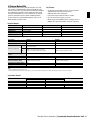
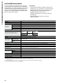
MELSEC Q Series Process Control CPUs
These CPUs include a wide variety of process control functions
optimized to the task of controlling large scale, complex continuous
processes where downtime is not an option. This allows a Q Series
system to fully address the needs of users outside of the scope of
traditional discrete control applications.
Key Features:
• 52 process control instructions added to standard instruction set
• Floating point math coprocessor dedicated to floating point and
process control operations
• Autotuning PID with 2 degrees of freedom (responds to both set
value and disturbance)
• Compensation functions to allow loop modeling closer to the
actual process
• Process alarm functions related to high, low and deviation process
and manipulated variable values
• Tracking functions to allow smooth transfer between manual and
automated control
• Hot swappable modules
• Increased functionality in Version C or later (S/N 07032x)
• SFC active step comment readout instruction
• Increased multiple CPU shared memory flexibility
• 1/1000 second resolution timestamp capability
• Store sampling trace data in Standard RAM
• Power supply error detection function
Required Manuals
Model Number
SH(NA)080316
Description
Contents
QnPHCPU/QnPRHCPU (Process
Control Instructions) Programming
Manual
Overview, structure & combinations of process control, instructions,
data used for process control instructions, how to execute PCI, execution
condition switching & functions, instruction list, how to read instruction list,
No (purchase separately)
I/O control instructions, control operator instructions, compensation operator
instructions, arithmetic operation instructions, comparison operation
instructions, auto tuning, error codes, appendices
Included with CPU?
Stk Item
-
Note: Many of these manuals are available by free download from our website, www.meau.com
Process Control CPUs
Model Number
Stocked Item
Programming
Language
Q02PHCPU
S
Sequence Control
Dedicated Language
Process Control
Language
LD X0
Processing
Speed (Sequence
MOV D0 D1
Instruction)
Program Capacity (*2, *3)
Program Memory
(Drive 0)
Memory Capacity Standard RAM (Drive 3)
Item
Standard ROM (Drive 4)
Maximum No. of
Stored Files
Q06PHCPU
S
Q12PHCPU
S
Q25PHCPU
-
Relay symbol language, logic symbolic language, MELSAP3 (SFC), MELSAP-L, Function block and structured text (ST)
FBD for process control (*1)
34ns
102ns
28k steps
60k steps
124k steps
252k steps
112k bytes
240k bytes
496k bytes
1008k bytes
128k bytes
112k byte
CPU Shared Memory
8k bytes
Program Memory
28
Standard RAM
3 (*6)
Standard ROM
28
Memory Card Interface
Yes
Max. I/O Device Points
8192 points (X/Y0 to 1 FFF)
Max. Physical I/O Points
4096 points (X/Y0 to FFF)
Communication Ports
USB (Type-B), RS-232
5VDC Internal Current Consumption
0.64A
Weight (kg)
0.20
Base Unit Slots Occupied
1
256k bytes (*4)
240k byte
496k byte
1008k byte
60
124
252 (*5)
60
124
252
Notes:
1. PX Developer is required for programming by FBD.
2. The unit of the file size stored in the memory area varies depending on the CPU module. For details, refer to the QCPU User’s Manual (Function Explanation, Program Fundamentals)
3. The maximum number of executable sequence steps is as shown. (Program capacity) - (File header size (default 34 steps)). Refer to the QCPU User’s Manual (Function Explanation, Program Fundamentals)
4. CPU shared memory is not latched.
5. The CPU module can only execute up to 124 programs.
6. Extended by the upgraded functions of the CPU module.
20
MELSEC Q Series Redundant CPUs
These CPUs take the process control capabilities of the Q Series
process CPUs and add full hot-backup capability by using dual
redundant CPUs. Use this system in applications where downtime
cannot be tolerated for reasons of safety, equipment damage, financial
loss, interruption of service, or regulatory compliance.
Key Features:
• Prevent controller downtime with dual redundant CPUs (control and
back-up). Any failure of the control CPU causes immediate transfer
of control to the back-up, preventing system failure or interruption.
• Synchronize up to 100,000 words of process data between CPUs
per scan
• Switchover time typically around 40ms, insuring
“bumpless” transfer
• CPUs reside on physically separate racks, allowing control CPU to
be replaced while back-up maintains system operation
• Low cost of ownership; most parts are interchangeable with
standard Q Series systems
• Redundant power supply option
• Redundant MELSECNET/H control level network provides link to I/O
stations at up to 25Mbit/s
• Over 50 process control related instructions (same as Q Process CPUs)
• Most I/O may be hot swapped
• Increased functionality in Version D or later (S/N 07032x)
• SFC active step comment readout instruction
• Increased multiple CPU shared memory flexibility
• 1/1000 second resolution timestamp capability
• Store sampling trace data in Standard RAM
• Power supply error detection function
Required Manuals
Use same manual set as shown for Q Series Process CPUs, plus the manual listed below.
Model Number
Description
Contents
Included?
Stocked Item
SH(NA)080486
QnPRHCPU User’s Manual
(Redundant System)
Overview, System Configuration, Tracking cable, Procedure for starting
up a redundant system, Redundant system functions, Redundant system
No (purchase separately) networks, Programming cautions, Troubleshooting, Processing time for
redundant systems
Note: Many of these manuals are available by free download from our website, www.meau.com
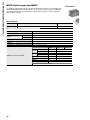
Redundant CPUs
Model Number
Stocked Item
Programming
Language
Q12PRHCPU
S
Sequence Control Dedicated
Language
Process Control Language
Processing
LD X0
Speed (Sequence
MOV D0 D1
Instruction)
Processing Speed
Tracking Execution Time
(Redundant
(Increased Scan Time)
Function)
Program Size
Program Memory (Drive 0)
Standard RAM (Drive 3)
Memory Size
Standard ROM (Drive 4)
Program Memory
Max. Number of
Files Stored
Standard ROM
Max. I/O Device Points (*1)
Max. Physical I/O Points (*2)
Max. CPUs Mounted
Q25PRHCPU
-
Relay symbol language, logic symbolic language, MELSAP3 (SFC), MELSAP-L, function block and structured text (ST)
FBD for process control (Programming by PX Developer)
34ns
102ns
Device memory 48k words: 10ms; Device memory 100k words: 15ms; QnPRHCPU User’s Manual (Redundant System)
124 steps
496k bytes
Size of the installed memory card (2M bytes max.)
496K bytes
124
124
8192 points (X/Y0 to 1FFF)
4096 points (X/Y0 to FFF)
1 (multiple-CPU configuration is not available)
252 steps
1008K bytes
1008K bytes
252
252
Max. Extension Base
0 (All non-redundant modules are mounted on the remote I/O station (the maximum number of modules that can be mounted
on a remote station is 64))
Max. Remote I/O Points
Number of Steps
Program Capacity
Number of Programs
8192 points (up to 2048 points per station)
124 ksteps
124
Functions Compatible With Redundant System
Redundant configuration of the entire system, including the CPU, the power supply, and the base unit. Hot standby system for
the control and standby systems online module change both backup and separate mode available. Large-capacity data tracking:
Large-capacity device data transfer (100 kwords) from the control system to the standby system. Network system compatible
with redundant system: Switchover in case of MELSECNET/H or Ethernet module malfunction or network wire disconnection.
Loop Control
Specs.
RAS
Control Cycle
Number of Control Loops
Main Functions
Online Module Replacement
Output In Case Of Error Stop
Communication Ports
Modules Mountable On Main Base Unit
Programming Software
5VDC Internal Current Consumption
Weight
Base Unit Slots Occupied
252 ksteps
252 (*3)
10 ms -/control loop (Can be set for each loop.)
No limit (*4)
2-degree-of-freedom PID control, cascade control, automatic tuning function, feed forward control
The I/O, analog, temperature input, temperature control, and pulse input modules can be replaced (on a remote I/O station).
Clear or output retention can be designated for each module.
USB (Type-B), RS-232
Network modules for the Q series can be mounted (Ethernet, MELSECNET/H, and CC-Link only)
GX Developer, PX Developer
0.89
0.30
2
Notes:
1. Total number of the I/O points on the main base unit, which are directly controlled from the CPU module, and the I/O points controlled as remote I/O by the remote I/O network.
2. The number of I/O points on the main base unit, which are directly controlled from the CPU module.
3. The max. number of files that can be executed is 124. Two SFC/MELSAP-Ls are available, one of which is a program execution control SFC.
4. The number of control loops is restricted by the combination of the device memory capacity (128 kwords/loop used) and the control cycle.
Mitsubishi Electric Automation
|
Programmable Automation Controller / PAC 21
n PROGRAMMABLE AUTOMATION CONTROLLER / PAC
Q Redundant CPU Parts
Product Name
Redundant CPU Module
Tracking Cable
Base Unit For Redundant
Power Supply Systems
Model
Overview
Q12PRHCPU
Q25PRHCPU
QC10TR
QC30TR
Q38RB
Q68RB
Q65WRB
Max. I/O device points: 8192 (physical I/O points: 4096), program capacity: 124 ksteps
Max. I/O device points: 8192 (physical I/O points: 4096), program capacity: 252 ksteps
1m cable for tracking
3m cable for tracking
Q series I/O mounting main base: Number of power supply slots: 2, number of CPU slots: 1, number of I/O slots: 8
Q series I/O mounting extension base: Number of power supply slots: 2, number of I/O slots: 8
Q series I/O mounting extension base: Dual Q Bus Inputs, Number of power supply slots: 2, number of I/O slots: 5
Stock
Item
S
S
S
S
100 to 120/200 to 240VAC input, 5VDC, 8.5 A output
-
Power Supply Module For Redundant
Q64RP
Power Supply Systems
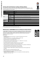
Communication and Networking Module Version Information For Compatibility With Redundant Systems
Product Name
MELSECNET/H
Master Module
Model Number
Overview
QJ71LP21-25
For MELSECNET/H dual optical loop interface module (compatible with SI and QSI)
control / normal / master stations
S
QJ71LP21S-25
For MELSECNET/H dual optical loop interface module (compatible with SI and QSI)
control / normal / master stations, equipped with an external power supply
-
For MELSECNET/H dual optical loop interface module (compatible with GI) control /
normal / master stations
For MELSECNET/H coaxial single bus interface module control / normal / master stations
For MELSECNET/H dual optical loop interface module (compatible with SI and QSI)
remote I/O stations (*1)
For MELSECNET/H dual optical loop interface module (compatible with GI) remote I/O
stations
For MELSECNET/H coaxial single bus interface module remote I/O stations
Ethernet interface module (10BASE2)
Ethernet interface module (10BASE5)
Ethernet interface module (100BASE-TX/10BASE-T)
For dual optical loop interface board (compatible with SI and QSI) control / normal
stations (*1)
For dual optical loop interface board (compatible with GI) control / normal stations (*1)
For coaxial single bus interface board control / normal stations (*1)
For CC-Link IE Control, dual-loop fiber control stations
For CC-Link IE Control, dual-loop fiber with redundant power control stations
QJ71LP21GE
QJ71BR11
QJ72LP25-25
MELSECNET/H
Remote I/O Module
QJ72LP25GE
QJ72BR15
QJ71E71-B2
QJ71E71-B5
QJ71E71-100
Ethernet
Interface Module
MELSECNET / H Board
For Personal Computers
CC-Link IE Control
Version
Q81BD-J71LP21-25
Q80BD-J71LP21G
Q81BD-J71BR11
QJ71GP21-SX
QJ71GP21S-SX
Note:
1. The boards must be used in combination with the attached driver package SW0DNC-MNETH-B[90K] or later version.
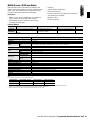
Sample Configurations
Non-redundant power supply configuration
Install a module with the
same module name into
the same slot.
System A Control System
System B Standby System
Q35B
QJ71E71
QJ61BT11
Q35B
QJ71LP21
Tracking cable
Q61P
Q12PRHCPU
Redundant power supply configuration
Make Redundant Power
supply module redundant
Make Redundant Power
supply module redundant
System B - Standby
System
System A Control System
Q38RB
Q38RB
Tracking cable
Q63RP/Q64RP
(Two modules mounted on Q38RB)
22
Q63RP/Q64RP
(Two modules mounted
on Q38RB)
Stock Item
S
S
Function version “D”
or later
S
S
S
S
-
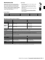
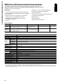
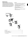
C Language CPU
The C Language CPU can be added to an iQ Platform or Q Series configuration and allows experienced C programmers to create custom
control programs using VxWorks (sold separately). This product is only meant for the advanced user. The Q12DCCPU-V is the hardware
base for the MES Interface IT e-F@ctory solution, and is included within the QJ71MES96IT Model Number.
Model Number
Q12DCCPU-V
Stocked Item
Certification
Endian Format (Memory Layout)
User File
Standard RAM
Capacity (For
User File
CompactFlash Card
Storage
Work RAM (for OS, Driver, User Program Execution)
Battery Backed-up RAM
Operating System (*1)
Software
Programming Language
Number of Channels
Interface (*2)
Ethernet
Number of Cascaded Stages
10BASE-T/
Maximum Segment Length (Distance
100BASE-TX
Between Hub and Node)
S
UL • cUL • CE
Little endian
3M bytes
Up to 8G bytes
128M bytes
128K bytes
VxWorks Version 6.4
C language (C/C++)
2 channels (same specification for CH1 and CH2 )
10BASE-T/100BASE-TX
Up to 4 (10BASE-T)/Up to 2 (100BASE-TX)
100m (328.08 feet)
Auto negotiation function (automatically recognizes 10BASE-T or 100BASE-TX); Auto-MDIX function (automatically
recognizes straight or crossing cable)
Transmission Speed
9600, 14400, 19200, 28800, 38400, 57600, 115200 bps
Transmission Distance
Up to 15m (49.21 feet)
RS-232
7/0.127_P HRV-SV outside diameter: 8.5mm (0.33 inches) or larger
Recommended Cable
(Oki Electric Cable Company, Limited Specify the number of pairs in_.)
Connector Applicable to External Wiring Round connector (10-pin)
Transmission Speed
12Mbps (Full Speed Mode: FS)
USB
Connector
Mini-B
Other Electric Characteristics
USB 2.0
Supply Power Voltage
3.3V ±5%
Supply Power Capacity
Up to 150mA
CompactFlash
Card
Card Size
TYPE I card TYPE II card is not allowed. I/O cards, such as a modem card are not allowed.
Number of Card Slots
1
Number of I/O Points (Number of Points Accessible to
4096 points (X/Y 0 to FFF)
Actual I/O Modules)
5VDC Internal Current Consumption
0.93A
Weight (kg)
0.24
Base Unit Slots Occupied
1
Supported Function
Notes:
1. For the development environment (personal computer), refer to the following manual. C Controller Module User’s Manual (Utility Operation, Programming)
2. The C Controller module differentiates 10BASE-T and 100BASE-TX according to the target device.
Mitsubishi Electric Automation
|
Programmable Automation Controller / PAC 23
n PROGRAMMABLE AUTOMATION CONTROLLER / PAC
B. MELSEC Q Series Base Units
The base unit (sometimes called a base rack) is the foundation of Q Series systems. All CPU modules are installed on it, along with a power
supply, I/O and special function modules. Besides providing physical support to the component modules, the base unit enables communication and power distribution between modules. The base unit can either be directly bolted to a panel, or mounted via DIN rail. In the case of DIN
rail mounting, the DIN rail Adapters must be used. Base units accommodate between 3 & 12 modules. For systems that require more modules
than be accommodated on the base unit, an extension base unit is required. These connect to the base unit via extension cables.
Required Manuals
Model Number
IB(NA)0800061
SH(NA)080483
Description
Contents
Included?
Stocked Item
QCPU(Q mode) CPU Module User’s
Manual (Hardware)
•
•
•
•
•
•
General specs
CE compliance information
Installation
Safety requirements
Power supply wiring
Overview of system parts
No (included with base units)
-
QCPU (Q Mode) User’s Manual
(Hardware Design, Maintenance &
Inspection)
•
•
•
•
•
•
•
•
PSU specs
CPU H/W specs
Base Unit specs
Memory Card specs
CE compliance information
Installation
Maintenance & inspection
Troubleshooting
No (purchase separately)
-
Note: Many of these manuals are available by free download from our website, www.meau.com
Base Units
Model Number
Q33B
Q35B
Q38B
Q38RB
Q312B
Stocked Item
Certification
Number of Expansion Slots
(Excluding 1st CPU Slot)
Applicable I/O and Intelligent
Function Modules
S
UL • cUL • CE
S
S
-
S
3
5
8
8
12
No
Yes
No
328 x 98 (12.92 x 3.86)
0.36
439 x 98 (17.30 x 3.86)
0.47
0.47
Redundant Power Supply Slot
Dimension (W x H) mm (in)
Weight (kg)
Accessories
Q Series/iQ Platform
No
No
189 x 98 (7.45 x 3.86)
245 x 98 (9.65 x 3.86)
0.21
0.27
4- M4 x 14 base unit mounting screws
MELSEC Q Series / iQ DIN Rail Adapters
Use these Adapters in situations where mounting of a base or extension unit on a DIN rail is required.
Note: DIN rail mounting is not recommended in locations where high vibration or mechanical shock exists.
Required Manuals
Model Number
SH(NA)080483
Description
Contents
Included?
Stocked Item
QCPU (Q Mode) User’s Manual
(Hardware Design, Maintenance &
Inspection)
• CPU H/W specs
• PSU specs
• Base Unit specs
• Memory Card specs
• CE compliance information
• Installation
• Maintenance & inspection
• Troubleshooting
No (purchase separately)
-
Note: Many of these manuals are available by free download from our website, www.meau.com
DIN Rail Mounting Adapters
Type
Applicable Base or Extension Base
Stocked Item
Q6DIN1
Q38B, Q312B, Q68B, Q612B
S
Q6DIN2
Q35B, Q65B, Q00JCPU-S8, Q00UJCPU
S
Q6DIN3
Q33B, Q52B, Q55B, Q63B
-
24
C. MELSEC Q Series / iQ Power Supply Modules
Power supply modules always fit on the left hand end of a rack. All base racks (Q3_B) must include a power supply, as
do powered extension racks (Q6_(R)B). We offer PSU to address worldwide AC voltage standards and DC power.
Model Number
Q61P
Q61P-D
Q62P
Q63P
Q64PN
Q63RP
Q64RP
Stocked Item
S
-
S
S
S
-
-
Certification
UL • cUL • CE
UL • cUL • CE
UL • cUL • CE
UL • cUL • CE
UL • cUL • CE
-
-
Applicable Base Units
Q3_DB, Q3_B, Q6_B
Input Power Supply
100-240VAC +10%/-15%
Input Frequency
Input Voltage Distortion Factor
Q3_RB, Q6_RB
24VDC +10%/-15%
100-240VAC
(+10%/-15%)
100 to 120VAC/
24VDC +30%/-35% 200 to 240VAC
(+10%/ -15%)
50/60Hz ±3Hz
-
50/60 Hz ±5%
50/60 Hz ±5%
50/60 Hz ±5%
5% or less
-
Within 5%
Within 5%
Within 5%
Max. Input Apparent Power
105VA
-
160 VA
65W
160VA
Inrush Current
20A within 8ms
100A within 1ms
20A within 8 ms
150A within 1ms
20A within 8ms
100-240VAC
+10%/-15%
5VDC
6A
3A
6A
8.5A
8.5A
8.5A
24VDC
-
0.6A
-
-
-
-
External Output Voltage
-
24VDC ±10%
-
-
-
-
Permissible Instantaneous Power
Failure Time
Within 20ms
Within 20ms
Within 10ms
Within 20ms
Within 10ms
Within 20ms
Operation Indication
LED indication (lit
at 5VDC output)
Weight (kg)
0.31
Base Unit PSU Slots Occupied
1
Rated Output
Current
LED indication and
LED indication (lit at 5VDC output)
power light
0.39
LED indication (Normal operation:
ON (green) Error: OFF (red))
0.33
0.40
0.60
0.47
2
D. MELSEC Q Series / iQ Extension Base Units and Connection Cables
Use extension base units (also known as extension racks) in systems that require more modules than can be accommodated on the main
base unit. Extension base units are available with a slot for an additional power supply (Q6_B) or without (Q5_B). Use Q6_B extension bases
in systems where the current supplied by the base unit power supply is insufficient for the whole system. Up to 7 extension base units may
be connected to the base unit, allowing a total of 8 bases. The 8 base units may be extended over a distance of up to 13.2 m (43.28 ft). The
maximum number of installed modules is 64. If your system requires more modules or greater distances, consider using a network to link the
system together. See the network section for more details.
Required Manuals
Model Number
IB(NA)0800061
SH(NA)080483
Description
Contents
• General specs
• CE compliance information
QCPU (Q mode) CPU Module
• Installation
User’s Manual (Hardware)
• Safety requirements
• Power supply wiring
• Overview of system parts
• CPU H/W
• PSU specs
• Base Unit specs
QCPU (Q Mode) User’s Manual
• Memory Card specs
(Hardware Design, Maintenance &
• CE compliance information
Inspection)
• Installation
• Maintenance & inspection
• Troubleshooting
Included?
Stocked Item
No (included with base units)
-
No (purchase separately)
-
Note: Many of these manuals are available by free download from our website, www.meau.com
Extension Base Units
Model Number
Q52B
Q55B
Q63B
Q65B
Q68B
Q68RB
Q612B
Q65WRB (*1)
Stocked Item
Certification
Number of Expansion Slots
Power Supply Module Slot
Redundant Power Supply Slot
S
UL • cUL • CE
2
No
No
S
UL • cUL • CE
5
No
No
UL • cUL • CE
3
Yes
No
S
UL • cUL • CE
5
Yes
No
S
UL • cUL • CE
8
Yes
No
UL • cUL • CE
8
Yes
Yes
S
UL • cUL • CE
12
Yes
No
S
UL • cUL • CE
5
Yes
Yes
Dimensions (W x H) mm (in)
106 x 98 (4.18
x 3.86)
189 x 98 (7.45
x 3.86)
189 x 98 (7.45
x 3.86)
245 x 98 (9.65
x 3.86)
328 x 98 (12.92 439 x 98 (17.30 439 x 98 (17.30 439 x 98 (17.30
x 3.86)
x 3.86)
x 3.86)
x 3.86)
Weight (kg)
0.14
0.23
0.23
0.28
0.38
0.49
0.48
0.52
Note:
1. The Q65WRB has dual Q Bus inputs for Local Extension I/O support in Redundant Systems.
Mitsubishi Electric Automation
|
Programmable Automation Controller / PAC 25
n PROGRAMMABLE AUTOMATION CONTROLLER / PAC
MELSEC Q Series / iQ Extension Cables for Extension Base Units
These cables are used to link main base units to extension base units. They are available in a variety of
lengths from 0.45m (1.48 ft.) to 10m (32.8 ft.).
Model Number
QC05B
QC06B
QC12B
QC30B
QC50B
QC100B
Stocked Item
S
S
S
S
S
S
Certifications
CE
CE
CE
CE
CE
CE
Cable Length (m (ft))
0.45 (1.48)
0.6 (1.97)
1.2 (3.93)
3 (9.84)
5 (16.39)
10 (32.79)
Weight (kg)
0.15
0.16
0.22
0.40
0.60
1.11
Required Manuals: Same as Base Units listed on previous page.
MELSEC Q Series Tracking Cable for QnPRH System
These cables are used to link redundant QnPRH CPU systems to insure data and programs are always
synchronized between the two processors.
Model Number
QC10TR
QC30TR
Stocked Item
S
-
Cable Length m (ft)
1.0 (3.29)
3.0 (9.87)
Weight (kg)
0.15
0.28
Required Manuals: Same as Base Units listed on previous page.
MELSEC Q Series / iQ RS-232 Communication Cable
Model Number
SC-Q
Stocked Item
S
Cable Length m (ft)
3 (9.84)
Connection Type
RS-232 Connection: 9 pin DSUB to Q Series front port connection
*Note Also compatible with ST Series I/O head station (see Distributed I/O section of this guide.)
26
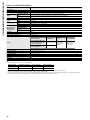
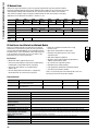
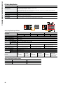
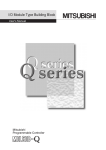
E. MELSEC Q Series / iQ Digital Input Modules
QX10
0 1 2 3 4 5 6 7
8 9 A B CDE F
QX28
0 1 2 3 4 5 6 7
QX41
0 1 2 3 4 5 6 7
8 9 A B CDE F
0 1 2 3 4 5 6 7
8 9 A B CDE F
24VDC
4mA
0
1
2
3
Digital input modules provide the CPU interface for monitoring on/off
voltage signals in your system.
4
5
6
7
8
9
A
B
C
Key Features:
D
E
F
COM
NC
•
•
•
•
Sense commonly used AC and DC voltages
Negative/positive common types
16, 32 or 64 inputs per module, depending on module type.
1-70ms software selectable input filter response time (via
GX Developer) for adjusting input response. This avoids the effects
of noise on the inputs
• DC input short circuit protection
• Internal optoisolation
• Removable terminal blocks
100VAC
8mA60Hz
7mA50Hz
0
1
2
3
4
5
6
7
8
9
A
B
C
D
E
F
0
1
2
3
4
5
6
7
8
9
A
B
C
D
E
F
COM
NC
100VAC
8mA60Hz
7mA50Hz
QX42
0 1 2 3 4 5 6 7
8 9 A B CDE F
0 1 2 3 4 5 6 7
8 9 A B CDE F
QX41
24VDC
4mA
QX70
0 1 2 3 4 5 6 7
8 9 A B CDE F
QX42
DISPLAY
F
L
0
1
2
3
4
5
6
7
8
9
A
B
C
D
E
F
QX71
0 1 2 3 4 5 6 7
8 9 A B CDE F
0 1 2 3 4 5 6 7
8 9 A B CDE F
5/12VDC
1.2 / 3.3mA
0
1
2
3
4
5
6
7
8
9
A
B
C
D
E
F
- +
COM
NC
5/12VDC
1.2mA
3.3mA
QX80
0 1 2 3 4 5 6 7
8 9 A B CDE F
QX72
0 1 2 3 4 5 6 7
8 9 A B CDE F
0 1 2 3 4 5 6 7
8 9 A B CDE F
QX71
5/12VDC
1.2/3.3mA
QX81
0 1 2 3 4 5 6 7
8 9 A B CDE F
0 1 2 3 4 5 6 7
8 9 A B CDE F
QX81
QX72
DISPLAY
F
L
0
0
1
2
3
4
5
6
7
8
9
A
B
C
D
E
F
1
2
3
4
5
6
7
8
9
A
B
C
D
E
F
NC
COM
24VDC
4mA
0
1
2
3
4
5
6
7
8
9
A
B
C
D
E
F
24VDC
4mA
• Established A Series connectors (FCN/D-sub type) on 32 & 64 I/O
modules for compatibility with existing A Series terminal block
(A6TBXY type) installations
If you need to monitor varying signal levels of voltage or current,
please refer to the analog input modules section. If you need to
monitor digital signals that change their state rapidly (more than
approximately 10 Hz, depending on program scan time), then
consider using high-speed counter modules.
Required Manuals
Model Number
SH(NA)080042
Description
Contents
Included?
Stocked Item
I/O Module Type Building Block User’s Manual
Specifications & wiring diagrams for all
Q Series digital I/O modules
No (purchase separately)
-
Note: Many of these manuals are available by free download from our website, www.meau.com
Q Series / iQ Input Modules
Model Number
QX10
QX28
QX40
QX40-S1
QX40H
QX41
QX41-S1
Stocked Item
S
-
S
S
-
S
-
Certification
UL • cUL • CE
Input Type
AC
AC
DC positive common (sink)
No. of Input Points
16
100-120VAC
+10%/-15%,
50/60Hz ±3Hz
16
15@100VAC,
50/60Hz
20@100VAC,
50/60Hz
8
100-240VAC
+10%/-15%,
50/60Hz ±3Hz
17 (@200
VAC/60Hz)/ 14
(@200 80@100
VAC/60Hz)/
VAC/50Hz) 7 (100
VAC/50Hz)
10@100VAC,
50/60Hz
20@100VAC,
50/60Hz
0.1/0.2/0.4/0.6/1
(*1)
0.1/0.2/0.4/0.6/1
1/5/10/20/70 (*1)
(*1)
Connection Type
Screw Terminals
Screw Terminals
Screw Terminals
Points/Common
16
Input Voltage
Input Current (mA)
8
16
16
32
32
24VDC +20%/
-15%, ripple ratio: 24VDC +20%/-15%
within 5%
6
4
24VDC +20%/-15%
4
8
16
16
.04/.10/.25/
.50/.95 (*1)
.04/.10/.25/
.50/.95 (*1)
Crimping
Terminal
8
32
32
Maximum 5VDC Current Consumption (mA) 50
50
50
60
80
75
75
Weight (kg)
0.17
0.2
0.16
0.2
0.16
0.15
0.15
Base Unit Slots Occupied
1
Response Time (ms)
OFF-ON
ON-OFF
1/5/10/20/70 (*1)
Screw Terminals
0.1/0.2/0.4/0.6/1
(*1)
0.1/0.2/0.4/0.6/1
1/5/10/20/70 (*1)
(*1)
1/5/10/20/70 (*1)
FCN x 1 (*2)
FCN x 1 (*2)
Notes: See notes next page.
Model Number
QX41-S2
QX42
QX42-S1
QX70
QX70H
QX71
QX72
Stocked Item
-
S
S
S
S
S
-
Certification
UL • cUL • CE
Input Type
DC positive common (sink)
DC positive/
common (sink)
DC positive/negative common (sink/
source)
No. of Input Points
32
64
16
32
Input Voltage
24VDC +20%/-15%
Input Current (mA)
6
DC positive/
negative common
(sink/source)
16
5/12VDC
+20%/-15%
1.2 / 3.3
64
Connection Type
FCN x 2 (*2)
FCN x 2 (*2)
FCN x 2 (*2)
Points/Common
32
32
32
Maximum 5VDC Current Consumption (mA) 75
90
90
55
Weight (kg)
0.15
0.18
0.18
0.14
Base Unit Slots Occupied
1
OFF-ON
ON-OFF
4
0.1/0.2/0.4/0.6/1
1/5/10/20/70 (*1) 1/5/10/20/70 (*1)
(*1)
0.1/0.2/0.4/0.6/1
1/5/10/20/70 (*1) 1/5/10/20/70 (*1)
(*1)
5VDC +20%/-15% 5/12VDC +20%/-15%
3
.04/.10/.25/
1/5/10/20/70 (*1)
.50/.95 (*1)
.04/.10/.25/
1/5/10/20/70 (*1)
.50/.95 (*1)
Crimping
Screw Terminals
Terminal
16
8
Response Time (ms)
4
64
1.2 / 3.3
1.2 / 3.3
1/5/10/20/70 (*1)
1/5/10/20/70 (* 1)
FCN x 1 (*2)
FCN x 2 (*2)
32
32
80
70
85
0.14
0.12
0.13
Notes: See notes next page.
Mitsubishi Electric Automation
|
Programmable Automation Controller / PAC 27
n PROGRAMMABLE AUTOMATION CONTROLLER / PAC
MELSEC Q Series / iQ Input Modules (Continued)
Model Number
QX80
QX80H
QX81
QX81-S2
QX82
QX82-S1
QX90H
Stocked Item
S
S
S
-
S
-
S
Certification
UL • cUL • CE
Input Type
DC negative common (source)
No. of Input Points
16
16
32
64
64
16
Input Voltage
24VDC +20%/-15%
24VDC +20%/-15%
24VDC +20%/-15%
24VDC +20%/-15%
24VDC +20%/-15%
5VDC +20%/-15%
Input Current (mA)
4
6
4
32
24VDC (+20/-15%,
ripple ratio within
5%)
6
4
4
6
OFF-ON
1/5/10/20/70 (*1)
.04/.10/.25/.50/.95
(*1)
1/5/10/20/70 (*1)
.05/.15/.3/.55/1.05
(*1)
.04/.10/.25/.50/.95
(*1)
ON-OFF
1/5/10/20/70 (*1)
.04/.10/.25 /.50/.95
(*1)
1/5/10/20/70 (*1)
.15/.2/.35/.6/1.1
(*1)
.04/.10/.25 /.50/.95
(*1)
19VDC/3mA
13V or higher/3mA
19VDC/3mA
19VDC/3mA
3.5V or higher/3mA
Response
Time (ms)
Minimum On Voltage/
Current
Maximum Off Voltage/
Current
Connection Type
Points/Common
Maximum 5VDC Current
Consumption (mA)
Weight (kg)
15VDC/3mA
19VDC/3mA
11VDC/ 1.7mA
8V or lower/1.6mA
11VDC/ 1.7mA
5VDC/ 1.7mA
11VDC/ 1.7mA
9.5VDC/1.5mA
1V or lower/1mA
Screw Terminals
Crimping Terminal
D-Sub (*3)
D-Sub
FCN x 2 (*2)
FCN x 2 (*2)
Crimping Terminal
16
8
32
32
32
32
8
50
80
75
75
90
90
80
0.16
0.16
0.16
0.18
0.18
0.14
0.16
Base Unit Slots Occupied 1
Notes:
1. Set response time by parameters in GX Developer. Default is 10ms (0.2ms for -S1 versions). Input and output response times cannot be set independently.
2. 40 pin FCN connector. Supplied separately. See “I/O Wiring Connectors” for ordering information.
3. 37 pin D-sub connector. Supplied separately. See “I/O Wiring Connectors” for ordering information.
MELSEC Q Series / iQ Combination I/O Modules
Combination input/output modules allow both input and output points to be combined in a single module. This offers
the chance to reduce the number of I/O modules, enabling a more compact system in some applications.
QH42P
0 1 2 3 4 5 6 7
8 9 A B CDE F
0 1 2 3 4 5 6 7
8 9 A B CDE F
QX48Y57
0 1 2 3 4 5 6 7
8 9 A B CDE F
FUSE
QY42P
24VDC4mA
DISPLAY
12/24VDC
F
L
0.1A
0
1
2
3
4
5
6
7
- +
Required Manuals
Model Number
SH(NA)080042
COM
L
8
9
L
L
Description
I/O Module Type Building
Block User’s Manual
Contents
Specifications & wiring diagrams for all Q
Series digital I/O modules
Included?
Stocked Item
No (purchase separately)
-
A
B
L
L
C
D
L
L
E
- +
COM
24VDC4mA
12/24VDC
0.5A
24VDC4mA QX41Y41P
DISPLAY
12/24VDC
F
L
0.1A
0
1
2
3
4
5
6
7
8
9
A
B
C
D
E
F
Note: Many of these manuals are available by free download from our website, www.meau.com
Combination I/O Modules
Model Number
QH42P
QX41Y41P (*1)
QX48Y57
Stocked Item
Certification
Input Type
No. of Input Points
Input Voltage
Input Current (mA)
OFF-ON
Response Time
(ms)
ON-OFF
Minimum On Voltage/Current
Maximum Off Voltage/Current
Points/Common
Output Type
No. of Output Points
Load Voltage
Maximum Load Current
OFF-ON
Response Time
(ms)
ON-OFF
S
UL • cUL • CE
DC positive common (sink)
32
24VDC +20%/-15%
4
1/5/10/20/70 (*2)
1/5/10/20/70 (*2)
19VDC/3mA
11VDC/1.7mA
32
Sink transistor
32
12-24VDC +20%/-15%
0.1A/pt, 2A/common
1
1 (rated resistive load)
S
S
32
8
32
8
32
7
0.1A/pt, 2A/common
0.5A/pt, 2A/common
External Supply Voltage/Current
Protection
Points/Common
Connection Type
Maximum 5VDC Current
Consumption (mA)
Weight (kg)
Base Unit Slots Occupied
12-24VDC +20%/-15%/15mA (24VDC)/common
Thermal & short circuit
Thermal & short circuit
32
32
FCN (*3)
FCN (*3)
Fused (4A), with blown fuse detection
7
Screw Terminals
130
80
130
0.2
1
Notes:
1. The QX41Y41P has consecutive I/O addressing, unlike the QH42P, and is meant to replace A Series I/O blocks.
2. Set response time by parameters in GX Developer. Default is 10ms (0.2ms for -S1 versions). Input and output response times cannot be set independently.
3. 40 pin FCN connector. Supplied separately. See “I/O Wiring Connectors” for ordering information.
28
QX41Y41P
0 1 2 3 4 5 6 7
8 9 A B CDE F
0 1 2 3 4 5 6 7
8 9 A B CDE F
MELSEC Q Series / iQ Digital Output Modules
QY10
0 1 2 3 4 5 6 7
8 9 A B CDE F
QY18A
0 1 2 3 4 5 6 7
8 9 A B CDE F
QY22
0 1 2 3 4 5 6 7
8 9 A B CDE F
QY40P
0 1 2 3 4 5 6 7
8 9 A B CDE F
QY41P
0 1 2 3 4 5 6 7
8 9 A B CDE F
0 1 2 3 4 5 6 7
8 9 A B CDE F
QY41P
12/24VDC
0.1A
Digital output modules provide the CPU interface for turning devices in your system on & off
under program control.
0
L
L
L
2
3
4
L
L
5
6
L
L
7
8
L
Key Features:
L
9
A
L
L
B
C
L
L
D
E
L
•
•
•
•
•
•
Relay (contact), sink & source transistor plus triac outputs to handle all common devices
16, 32 or 64 outputs per module, depending on module type
Thermal & short-circuit protection on some modules
Internal optoisolation
Removable terminal blocks
Established A Series connectors (FCN/D-sub type) on 32 & 64 I/O modules for
compatibility with existing A Series terminal block (A6TBXY type) installations
• If you need to produce varying signal levels of voltage or current, please refer to the
analog output modules section.
L
0
1
2
3
4
5
6
7
8
9
A
B
C
D
E
F
1
L
F
COM
NC
24VDC
240VAC
2A
QY50
0 1 2 3 4 5 6 7
8 9 A B CDE F
FUSE
0
L
L
L
2
3
4
L
L
5
6
L
L
7
8
L
L
9
A
L
L
B
C
L
L
D
E
L
L
0
1
2
3
4
5
6
7
8
9
A
B
C
D
E
F
1
L
F
COM
12VDC
24VDC
0.5A
0
L
1
L
2
L
3
L
4
L
5
L
6
L
7
L
NC
NC
24VDC
240VAC
2A
0
1
2
3
4
5
6
7
8
9
A
B
C
D
E
F
QY68A
0 1 2 3 4 5 6 7
0
L
L
1
2
L
L
3
4
L
L
5
6
L
L
7
8
L
L
9
A
L
L
B
C
L
L
D
E
L
L
F
COM
100VAC
240VAC
0.6A
QY70
0 1 2 3 4 5 6 7
8 9 A B CDE F
FUSE
1
L
2
L
3
L
4
L
5
L
6
L
7
L
NC
NC
5/12/
24VDC
2A
0
L
L
1
2
L
L
3
4
L
L
5
6
L
L
7
8
L
L
9
A
L
L
B
C
L
L
D
E
L
L
F
COM
12VDC
24VDC
0.1A
0
1
2
3
4
5
6
7
8
9
A
B
C
D
E
F
0
L
L
1
2
L
L
3
4
L
L
5
6
L
L
7
8
L
L
9
A
L
L
B
C
L
L
D
E
L
L
F
COM
5VDC
12VDC
16mA
QY42P
12/24VDC DISPLAY
F
L
0.1A
0
1
2
3
4
5
6
7
8
9
A
B
C
D
E
F
QY71
0 1 2 3 4 5 6 7
8 9 A B CDE F
0 1 2 3 4 5 6 7
8 9 A B CDE F
5/12VDC
16mA
0
L
0
1
2
3
4
5
6
7
8
9
A
B
C
D
E
F
QY42P
0 1 2 3 4 5 6 7
8 9 A B CDE F
0 1 2 3 4 5 6 7
8 9 A B CDE F
QY80
0 1 2 3 4 5 6 7
8 9 A B CDE F
FUSE
0
L
0
1
2
3
4
5
6
7
8
9
A
B
C
D
E
F
QY81P
0 1 2 3 4 5 6 7
8 9 A B CDE F
0 1 2 3 4 5 6 7
8 9 A B CDE F
QY81P
QY71
FUSE
L
1
2
L
L
3
4
L
L
5
6
L
L
7
8
L
L
9
A
L
L
B
C
L
L
D
L
E
F
L
- +
COM
12VDC
24VDC
0.5A
12/24VDC
0.1A
0
1
2
3
4
5
6
7
8
9
A
B
C
D
E
F
Model Number
QY10
QY18A
QY22
QY40P
QY41P
QY42P
Stocked Item
S
S
S
S
S
S
Certification
UL • cUL • CE
UL • cUL • CE
UL • cUL • CE
UL • cUL • CE
UL • cUL • CE
UL • cUL • CE
Output Type
Relay
Isolated Relay
Triac
Sink Transistor
Sink Transistor
Sink Transistor
No. of Output Points
16
8
16
16
32
64
Load Voltage
24VDC/240VAC
24VDC/240VAC
100-240VAC, +5%
12-24VDC, +20/-15%
12-24VDC, +20/-15%
12-24VDC, +20/-15%
Maximum Load Current
2A/pt, 8A/common
2A/point
0.6A/pt, 4.8A/common 0.1A/pt, 1.6A/common 0.1A/pt, 2.0A/common 0.1A/pt, 2.0A/common
OFF-ON
10
10
ON-OFF
12
12
1
1ms+0.5 cycle (rated
resistive load)
External Supply Voltage/Current
N/A
N/A
Protection
N/A; use surge
suppressor
Points/Common
16
Connection Type
Maximum 5VDC Current
Consumption (mA)
Weight (kg)
Screw Terminal
N/A; use surge
suppressor
All points
interdependent
Screw Terminal
430
0.22
Base Unit Slots Occupied
1
Model Number
QY50
QY68A
QY70
QY71
QY80
QY81P
QY82P
Stocked Item
S
S
-
-
S
S
S
Certification
UL • cUL • CE
High current sink
Transistor
16
12-24VDC, +20/
-15%
0.5A/pt, 4.0A/
common
1
1 (rated resistive
load)
12-24VDC (+20/
-15%) 20mA
UL • cUL • CE
Independent sink/
source Transistor
8
5-24VDC, +20/
-10%
UL • cUL • CE
UL • cUL • CE
UL • cUL • CE
UL • cUL • CE
UL • cUL • CE
Sink Transistor
Sink Transistor
Source Transistor
Source Transistor
Source Transistor
3
16
5-12VDC, +25/
-10%
16mA/pt, 256mA/
common
0.5
32
5-12VDC, +25/
-10%
16mA/pt, 512mA/
common
0.5
10 (resistive load)
0.5 (resistive load)
0.5 (resistive load)
N/A
5/12VDC (+25/
-10%), 90mA
5/12VDC (+25/
-10%), 170mA
16
12-24VDC, +20/
-15%
0.5A/pt, 4A/
common
1
1 (rated resistive
load)
12-24VDC (+20/
-15%)
Fuse (4A)
N/A
Fuse (1.6A)
Fuse (1.6A)
Fuse (4A)
32
12-24VDC, +20/
-15%
0.1A/pt, 2A/
common
1
1 (rated resistive
load)
12-24VDC (+20/
-15%)
Thermal & shortcircuit
64
12-24VDC, +20/
-15%
0.1A/pt, 2A/
common
1
1 (rated resistive
load)
12-24VDC (+20/
-15%)
Thermal & shortcircuit
16
32
16
32
64
Screw Terminal
FCN
Screw Terminal
D-sub (*1)
FCN x2
Response
Time (ms)
Output Type
No. of Output Points
Load Voltage
Maximum Load Current
Response
Time (ms)
OFF-ON
ON-OFF
External Supply Voltage/Current
Protection
N/A
RC surge suppressor
1
1
1
1 (rated resistive load) 1 (rated resistive load) 1 (rated resistive load)
12-24VDC (+20/-15%) 12-24VDC (+20/-15%) 12-24VDC (+20/-15%)
10mA
10mA
10mA
Thermal &
Thermal & short-circuit Thermal & short-circuit
short-circuit
16
16
32
64
Screw Terminal
Screw Terminal
FCN (*1)
FCN x 2 (*1)
240
250
65
105
150
0.22
0.4
0.16
0.15
0.17
2A/pt, 8A total
Points/Common
16
Connection Type
Maximum 5VDC Current
Consumption (mA)
Weight (kg)
Screw Terminal
All points
interdependent
Screw Terminal
80
110
95
150
80
95
160
0.17
0.14
0.14
0.14
0.17
0.15
0.15
Base Unit Slots Occupied
1
Notes:
1. Supplied separately. See “I/O Wiring Connectors” for ordering information.
Mitsubishi Electric Automation
|
Programmable Automation Controller / PAC 29
n PROGRAMMABLE AUTOMATION CONTROLLER / PAC
MELSEC Q Series / iQ I/O Terminal Blocks and Covers
A6CON1, A6CON2, A6CON3, A6CON4
The 16 point Q Series I/O Modules terminal blocks and covers are available separately. Use
these to replace original parts or to prepare wiring harnesses.
Model Number
K08H07500150
K08H07500151
Description
Stocked Item
Q Series I/O terminal block assembly (screw terminals, cover
door and label)
Q Series I/O terminal block cover door and label only
A6CON1E, A6CON2E, A6CON3E
-
Note: Many of these manuals are available by free download from our website, www.meau.com
MELSEC Q Series / iQ I/O Wiring Connectors
For the modules listed in the preceding I/O module sections, where connection type is given as “FCN” or
“D-sub”, use the following connectors:
Model Number
Certification
Number of Pins
Wiring Type
Connector Type
Stocked Item
A6CON1
A6CON2
A6CON3
A6CON1E
A6CON2E
A6CON3E
A6CON4
UL • cUL
UL • cUL
UL • cUL
UL • cUL
UL • cUL
UL • cUL
-
40
40
40
37
37
37
40
Solder
Crimp
IDC
Solder
Crimp
IDC
Solder
FCN
FCN
FCN
D-Sub
D-Sub
D-Sub
FCN
S
S
S
S
-
Note: A6CON4 has a bidirectional cable clamp which allows installation depth to be reduced.
MELSEC Q Series / iQ Remote Terminal Blocks
For QXx1, QXx2, QYx1 and QYx2 type I/O modules, the following remote terminal blocks can be used to make I/O connections.
Required Manuals
Model Number
Description
Contents
Included?
Stocked Item
SH(NA)080042
I/O Module Type Building Block User’s Manual
Specifications & wiring diagrams for all Q Series digital
I/O modules
No (purchase separately)
-
Note: Many of these manuals are available by free download from our website, www.meau.com
Connector / Terminal Block Converter Modules
Model Number
Details
Dimensions (W x H x D)
Applicable Models
QX41, QX41-S1, QX42,
QX42-S1, QY41P, QY42P,
QH42P, QX41Y41P
LY41NT1P, LY42NT1P,
LY41PT1P, LY42PT1P
Stocked Item
A6TBXY36
32 point terminal block (standard type)
120 x 78.5 x 52
A6TBXY54
32 point terminal block (2-wire type)
155 x 78.5 x 52
A6TBX70
32 point terminal block (3-wire type)
190 x 78.5 x 52
QX41, QX41-S1, QX42,
QX42-S1, QH42P, QX41Y41P
A6TBX36-E
For source type input modules (standard type)
120 x 78.5 x 52
QX81
S
A6TBY36-E
For source type output modules (standard type)
120 x 78.5 x 52
QY81P
S
A6TBX54-E
For source type input modules (2-wire type)
155 x 78.5 x 52
QX81
-
A6TBY54-E
For source type output modules (2-wire type)
155 x 78.5 x 52
QY81P
-
A6TBX70-E
For source type input modules (3-wire type)
190 x 78.5 x 52
QX81
-
S
-
MELSEC Q Series / iQ Remote Terminal Block Cables
Use the following cables to make connections between Q Series / iQ I/O modules and the terminal blocks listed above.
Model Number
Details
Weight (kg)
AC05TB
0.5m (19.69 in), for sink modules
0.17
Applicable Models
AC10TB
1 m (39.37 in), for sink modules
0.23
AC20TB
2 m (78.74 in), for sink modules
0.37
AC30TB
3 m (118.11 in), for sink modules
0.51
AC50TB
5 m (196.85 in), for sink modules
0.76
AC80TB
8 m (314.96 in), for sink modules (common current not exceeding 0.5A)
1.2
-
AC100TB
10 m (393.7 in), for sink modules (common current not exceeding 0.5A)
1.5
-
AC05TB-E
0.5m (19.69 in), for source modules
0.17
AC10TB-E
1 m (39.37 in), for source modules
0.23
AC20TB-E
2 m (78.74 in), for source modules
0.37
AC30TB-E
3 m (118.11 in), for source modules
0.51
AC50TB-E
5 m (196.85 in), for source modules
0.76
S
A6TBXY36, A6TBXY54, A6TBX70
A6TBX36-E, A6TBY36-E, A6TBX54-E,
A6TBY54-E, A6TBX70-E
Notes:
• “-E” cables use DSUB connectors, non “-E” cables use FCN connectors.
• The number of connectable I/O points is 32 for all connector/terminal block convertor modules. Two connector/terminal block converter modules and two
cables for connector/terminal block converter modules are required for 64-point I/O modules.
30
Stocked Item
S
-
MELSEC Q Series / iQ Analog Input Modules
Q64AD
Analog input modules provide an interface to the CPU for sensing
variable real world levels of voltage and current signals. These signals
are converted into digital values by the modules for use in programs.
This enables the CPU to process variable signals such as pressure,
speed & flow. For modules able to sense temperature, please refer to
the Temperature Input modules section.
Q68ADI
Q68ADV
RUN
RUN
ERROR
ERROR
RUN
• Voltage & current inputs, or exclusively voltage or
current input
• 4 and 8 channel input versions
• Fast conversion (80 microseconds/channel)
• High accuracy (± 0.1%)
• High resolution (1 part in ±16,000 or 14 bits)
• Switchable resolution (1 part in ±4000, 1 part in ±12,000 & 1 part
in ±16,000)
• Averaging function
• Module temperature drift compensation
• Maximum and minimum value hold
V+
I+
V+
V-
I+
SLD
V-
I+
SLD
V+
7
9
10
11
12
13
V-
C
H
4
5
6
8
V+
C
H
3
3
4
SLD
C
H
2
1
2
V-
C
H
1
I+
14
15
SLD
A.G.
16
V+
C
H
1
V-
C
H
2
V-
C
H
3
V-
V+
V+
V+
C
H
4
C
H
5
V-
V+
V-
V+
C
H
6
V-
C
H
7
V-
C
H
8
V-
V+
V+
A.G.
17
(FG)
A/D
0-±10V
0-20mA
Key Features:
• Module set-up via menus in GX Developer; no programming
required (requires use of GX Configurator-AD plug in)
• GX Configurator-AD reduces maintenance time with clear
presentation of module status
18
ERROR
1
2
3
4
5
6
7
8
9
10
11
12
13
14
15
16
C
H
1
I+
I+
C
H
2
I-
C
H
3
I-
C
H
5
6
7
I+
9
8
II+
I-
C
H
7
I-
I+
I+
C
H
8
IA.G.
18
A/D
0-±10V
10
11
12
13
14
15
16
17
17
(FG)
5
I+
I-
C
H
6
3
4
I+
C
H
4
1
2
I-
(FG)
18
A/D
0-20mA
Required Manuals
Model Number
SH(NA)080055
Description
Contents
Included?
Stocked Item
Analog-Digital Converter Module User’s Manual
Covers Q64AD, Q68ADV, Q68ADI &
GX Configurator-AD
Supplied as PDF with
GX Configurator-AD
-
Yes
-
IB(NA)0800034E Analog-Digital (Converter Module User’s Manual (Hardware) Basic Information on Q64AD, Q68ADV, Q68ADI
Note: Many of these manuals are available by free download from our website, www.meau.com
Analog to Digital Converter Modules
Model Number
Q64AD
Q68ADV
Q68ADI
Stocked Item
S
S
S
Certification
UL • cUL • CE
UL • cUL • CE
UL • cUL • CE
Number of Analog Input Points
4 points (4 channels)
8 points (8 channels)
8 points (8 channels)
Analog Input
Voltage
-10 to 10VDC (input resistance value 1MΩ)
Current
0 to 20mADC (input resistance value 250Ω)
Digital Output
-
0 to 20mADC (input resistance value 250Ω)
16-bit signed binary (Normal resolution mode: -4096 to 4095, high resolution mode: -12288 to 12287, -16384 to 16383
Analog Input Range
0 to 10V
0 to 5V
1 to 5V
-10 to 10
User range setting
0 to 20mA
4 to 20mA
User range setting
Voltage
I/O Characteristics Max. Resolution
Current
Normal Resolution Mode
Digital Output Value
Max. Resolution
0 to 4000
2.5mV
0 to 4000
1.25mV
0 to 4000
1.0mV
-4000 to 4000
2.5mV
-4000 to 4000
0.375mV
0 to 4000
5μA
0 to 4000
4μA
-4000 to 4000
1.37μA
Normal Resolution Mode
Ambient Temperature 0 to 55°C
Analog Input Range
With Temp. Drift
Compensation
Accuracy (Accuracy of Digital Output
Value Relative to Maximum Value) (*1)
Voltage
Current
0 to 10V
-10 to 10
0 to 5V
1 to 5V
User Range Setting
0 to 20mA
4 to 20mA
User Range Setting
±0.3% (±12 digit)
Without
Temp. Drift
Compensation
±0.4% (±16 digit)
High Resolution Mode
Digital Output Value
0 to 16000
0 to 12000
0 to 12000
-16000 to 16000
-12000 to 12000
0 to 12000
0 to 12000
-12000 to 12000
Max. Resolution
0.625mV
0.416mV
0.333mV
0.625mV
0.333mV
1.66μA
1.33μA
1.33μA
High Resolution Mode
Ambient
Temperature
25±5°C
Ambient Temperature 0 to 55°C
Ambient
Temperature
25±5°C
With Temp. Drift
Compensation
Without
Temp. Drift
Compensation
±0.3% (±48 digit)
±0.4% (±64 digit)
±0.1% (±16 digit)
±0.3% (±36 digit)
±0.3% (±48 digit)
±0.1% (±12 digit)
±0.1% (±48 digit)
Conversion Time
80 μs/channel (When temperature drift compensation is provided, time is 160 μs longer, regardless of the number of channels used.)
Absolute Max. Input
Voltage: ±15V, current: ±30mA
Insulation System
Across I/O terminals and PLC power supply: Photocoupler insulation; Across channels: No insulation
I/O Device Points Occupied
16 points (I/O allocation: 16 intelligent points)
Connection Terminal
18-point terminal block
Internal Current Consumption (5VDC) (A) 0.63
0.64
0.64
Weight (kg)
0.18
0.19
0.19
Base Unit Slots Occupied
1
Notes:
1. “Digit” indicates a digital value. ±4 digit means that the digital value 1000 will vary between 996 and 1004.
Mitsubishi Electric Automation
|
Programmable Automation Controller / PAC 31
n PROGRAMMABLE AUTOMATION CONTROLLER / PAC
MELSEC Q Series / iQ Isolated Analog Modules
Q64AD-GH
RUN
For some applications, it is essential that there is channel-to-channel isolation between analog inputs or outputs. These
modules provide galvanic isolation between each channel so there is no common connection from one channel to any other.
1
V+
C VH
I+
1
SLD
V+
C VH
I+
2
SLD
Description
Contents
Included?
Stocked Item
SH(NA)080277
Supplied as PDF with
GX Configurator-AD
S
IB(NA)0800223
Q64AD-GH Channel Isolated High Resolution Analog-Digital
Converter Module
Yes
S
Basic information on Q64AD-GH
8 CH Analog Module (Isolated Analog)
Model Number
Q68AD-G
Stocked Item
S
Certification
UL • cUL • CE
Number of Analog Inputs
8 points (8 channels)
Digital Output
16-bit signed binary (normal resolution mode: -4096 to 4095, high resolution mode: -12288 to 12287, -16384 to 16383)
Voltage
-10 to 10VDC (Input impedance 1ΩM or more)
Current
0 to 20mADC (Input resistance 250Ω)
Input
Analog Input Range
Voltage
0 to 5V
0 to 5V
1 to 5V
1 to 5V (Expanded Mode)
I/O Characteristics Maximum Resolution
-10 to 10V
2.5mV
-16000 to 16000 0.625mV
-12000 to 12000 0.333mV
5µA
4µA
0 to 12000
1.66µA
1.33µA
4 to 20V (Expanded Mode) -1000 to 45000
4µA
-3000 to 13500
1.33µA
User Range Setting
1.37µA
-12000 to 12000 1.33µA
0 to 20 mA
4 to 20 mA
Accuracy (Accuracy
Relative to Maximum
Analog Output Value)
High Resolution Mode
Digital Output
Maximum
Value
Resolution
0 to 1600
0.625mV
0.416mV
0 to 1200
0.333mV
-3000 to 13500 0.333mV
0.375
User Range Setting
Current
Normal Resolution Mode
Digital Output
Maximum
Value
Resolution
2.5mV
0 to 4000
1.25mV
1.0mV
-1000 to 4500
1.0mV
-4000 to 4000
0 to 4000
-4000 to 4000
Reference Accuracy
(*1)
±0.1%; Normal resolution mode : ±4digit (*2); High resolution mode (0 to 10V, -10 to 10V): ±16digit (*2)
High resolution mode (Other than the above ranges): ±12digit (*2)
Temp. Coefficient
(*3)
±71.4ppm/°C (0.00714%/°C)
Conversion Speed
10ms / channel
I/O Device Points Occupied
16 points
Isolated Part
Between I/O Terminal and Programmable
Controller Power Supply
Isolation Specifications
Between Analog Input Channels
Connector Type
A6CON1 or A6CON4
Internal Current Consumption (5VDC)
0.46A
Weight (kg)
0.16
Base Unit Slots Occupied
1
Isolation Method
Dielectric Strength
Insulation
Resistance
Transformer Isolation
500VAC rms,
1min.
1000VAC rms,
1min.
500VDC 10MΩ
or more
Notes:
1. Accuracy of offset/gain setting at ambient temperature
2. “digit” indicates a digital value.
3. Accuracy per temperature change of 1°C Example: Accuracy when temperature changes from 25 to 30°C ±0.1% (reference accuracy) + 0.00714 %/°C (temperature coefficient) x 5°C (temperature change
difference) = 0.1357%
32
6
7
8
9
12
SLD
Channel Isolated High Resolution Analog-Digital Converter Module Covers Q64AD-GH, Q62AD-DGH &
User’s Manual
GX Configurator-AD
4
SLD
A/D
-10 10V
0 20mA
Model Number
3
10
C VH
I+
4
Required Manuals
2
5
V+
C VH
I+
3
V+
Analog Input
ALM
ERR.
11
13
14
15
16
17
18
High Resolution Analog Module (Isolated Analog Input Channels)
Model Number
Q64AD-GH
Stocked Item
S
Certification
UL • cUL • CE
Number of Analog Input Points
Analog Input
4 points (4 channels)
Voltage
-10 to 10VDC (Input resistance 1MΩ)
Current
0 to 20 mADC (Input resistance 250Ω)
Digital Output
16-bit signed binary (-32768 to 32768); 32-bit signed binary (-65536 to 65536)
Input
Voltage
I/O Characteristics Maximum Resolution
Current
Accuracy (Accuracy
Relative to Full-Scale)
32-BIt
16-Bit
Digital
Digital
Output Value Output Value
(32-Bit)
(16-Bit)
156.3µV
78.2µV
62.5µV
312.6µV
156.4µV
125.0µV
0 to 64000
0 to 32000
47.4µV
94.8µV
156.3µV
312.6µV
47.4µV
94.8µV
-64000 to
64000
-32000 to
32000
312.5nA
250.0nA
625.0µV
500.0µV
Users Input Range
151.6nA
(Uni-Polar)
0 to 64000
0 to 32000
303.2µV
Analog Input
Range
0 to 10V
0 to 5V
1 to 5V
Users Input Range
(Uni-Polar)
-10 to 10V
Users Input Range
(Bi-Polar)
0 to 20 mA
4 to 20 mA
Maximum Resolution
Reference Accuracy (*1)
±0.05%; Digital output value( 32 bit): ±32 digit (*2); Digital output value (16 bit): ±16 digit (*2)
Temp. Coefficient (*3)
±71.4 ppm / °C (0.00714% / °C)
Conversion Speed
10ms / 4 channels
Absolute Maximum Input
Voltage: ± 15V; Current: ± 30mA
Withstanding Voltage Isolation Method
Between I/O terminal and PLC power supply: Photocoupler insulation; Between analog input channels: transformer isolation
Dielectric Strength
1780VAC ms / 3 cycles (elevation 2000m)
Isolation Voltage
Between I/O terminal and PLC power supply: 500VDC 20MΩ more
I/O Device Points Occupied
16 points
Connected Terminal
18 points terminal block
Applicable Solderless Terminals
R1.25-3 (A solderless terminals with sleeves cannot be used)
Internal Current Consumption (5VDC)
0.89 A
Weight (kg)
0.20
Base Unit Slots Occupied
1
Notes:
1. Accuracy when consistent at some temperature within the ambient temperature (to 55°C)
2. “Digit” indicates a digital output value.
3. Accuracy per temperature change of 1°C. Example: Accuracy when temperature change from 25 to 30°C. 0.05% (reference accuracy + 0.00714% / °C (temperature coefficient) x 5 °C
(temperature change difference) = 0.0857%
Mitsubishi Electric Automation
|
Programmable Automation Controller / PAC 33
n PROGRAMMABLE AUTOMATION CONTROLLER / PAC
Q62AD-DGH
RUN
ALM
ERR.
Isolated Analog Input Module with Signal Conditioning Function
CH1
P
I/CHK+
CHK-
1
2
3
4
5
6
7
CH2
P
I/CHK+
CHK-
8
9
10
11
12
13
14
IN
24VDC
15
16
17
FG
4~20mA
Required Manuals
Model Number
Description
Contents
Included?
Stocked Item
SH(NA)080277
Channel Isolated High Resolution Analog-Digital Converter
Module User’s Manual
Covers Q64AD-GH, Q62AD-DGH & GX
Configurator-AD
Supplied as PDF with
GX Configurator-AD
-
IB(NA)0800224
Channel Isolated High Resolution Analog-Digital Converter
Module (with Signal Conditioning Function)
Basic information on Q62AD-DGH
Yes
-
Isolated Analog Input Module with Signal Conditioning Function
Model Number
Q66AD-DG
Stocked Item
S
Certification
UL • cUL • CE
Input
Specification
Connecting
Section
with 2-Wire
Transmitter
Supply Power
Specification
Number of
Analog Input
6 points (6 channels)
Analog Input
4 to 20 mADC (Input resistance 250Ω)
Supply Voltage
26 ±2VDC
Maximum
Supply Current
24mADC
Short-Circuit
Protection
Available; Limit current: 25 to 35mA
Check Terminals
Digital Output
Available
16-bit signed binary (normal resolution mode: -96 to 4095, high resolution mode: -288 to 12287)
Normal Resolution Mode
Digital Output
Maximum
Value
Resolution
0 to 20mA
5µA
0 to 4000
4 to 20mA
4µA
4 to 20mA (Expanded Mode) -1000 to 4500
4µA
User Range Setting (*4)
0 to 4000
1.37µA
Analog Input Range
I/O Characteristics Maximum Resolution
Reference
Accuracy (*1)
Accuracy
(Accuracy Relative to Full-Scale) Temp.
Coefficient (*3)
Conversion Speed
High Resolution Mode
Digital Output Maximum
Value
Resolution
1.66µA
0 to 12000
1.33µA
-3000 to 13500 1.33µA
0 to 12000
1.33µA
±0.1% (Normal resolution mode: ±4digit (*2) High resolution mode: ±12digit (*2))
±71.4 ppm / °C (0.00714% / °C)
10ms / channel
Isolated Part
Between I/O Terminal and Programmable
Controller Power Supply
Insulation
Between Analog Input Channels
Between External Power Supply and Analog Input
Insulation Method
Dielectric Withstand
Isolation Voltage
Voltage
500VAC rms, 1min
Transformer
Isolation
500VDC 10MΩ
1000VAC rms, 1min. or more
500VAC rms, 1min
I/O Device Points Occupied
16 points
Connected Terminal
18 points terminal block
Connector Type
A6CON4
Internal Current Consumption (5VDC)
0.42 A
External Power Supply
24VDC +20%, -15%; Ripple, spike within 500mVp-p; Inrush current: 5.0A, within 400µs; 0.36A
Weight (kg)
0.22
Base Unit Slots Occupied
1
Notes:
1. Accuracy of offset/gain setting at ambient temperature
2. “digit” indicates a digital value.
3. Accuracy per temperature change of 1°C. Example: Accuracy when temperature changes from 25 to 30°C 0.1% (reference accuracy) + 0.00714 % / °C (temperature coefficient) x 5°C
(temperature change difference) = 0.1357%
34
18
High Resolution Isolated Analog Input Module with Signal Conditioning Function
Model Number
Q62AD-DGH
Stocked Item
S
Certification
CE
Input
Specification
Connecting
Section
With 2-Wire
Transmitter
Supply Power
Specification
Number of
Analog Input
2 points (2 channels)
Analog Input
4 to 20 mADC (*1) (Input resistance 250Ω)
Supply Voltage
26 ±2VDC
Maximum
Supply Current
24mADC
Short-Circuit
Protection
Available; Limit current: 25 to 35mA
Check Terminals
Digital Output
Available
16-bit signed binary (-768 to 32767); 32-bit signed binary (-1538 to 65535)
Analog Input
Range
I/O Characteristics Maximum Resolution
Accuracy (Accuracy Relative to
Full-Scale)
Maximum Resolution
32-BIt
16-Bit
4 to 20mA
250.0nA
500.0nA
User range
Setting
151.6nA
303.2nA
Digital
Digital Output
Output Value
Value (16-Bit)
(32-Bit)
0 to 64000
0 to 32000
Reference
Accuracy (*2)
±0.05%; Digital output value( 32 bit): ±32 digit (*3); Digital output value (16 bit): ±16 digit (*3)
Temp.
Coefficient (*4)
±71.4 ppm / °C (0.00714% / °C)
Conversion Speed
10ms / 2 channels
Insulation
Isolated Part
Insulation Method
Between I/O Terminal and PLC Power Supply
Photocoupler Insulation
Between Analog Input Channels
Transformer Isolation
Between External Power Supply and Analog Input Transformer Isolation
Dielectric Strength
Isolation
Voltage
1780VAC rms / 3
cycles (elevation
2000m)
500VDC 10MΩ
or more
I/O Device Points Occupied
16 points
Connected Terminal
18 points terminal block
Applicable Solderless Terminals
R1.25-3 (A solderless terminals with sleeves cannot be used)
Internal Current Consumption (5VDC)
0.33 A
External Power Supply
24VDC +20%, -15%; Ripple, spike within 500mVp-p; Inrush current: 5.5A, within 200µs; 0.19A
Weight (kg)
0.19
Base Unit Slots Occupied
1
Notes:
1. User range setting is 2 to 24mA
2. Accuracy of offset/gain setting at ambient temperature. Q62AD-DGH needs to be powered on 30 minutes prior to operation for compliance to the specification (accuracy)
3. “Digit” indicates a digital output value.
4. Accuracy per temperature change of 1°C.
Example: Accuracy when temperature change from 25 to 30°C. 0.05% (reference accuracy + 0.00714% / °C (temperature coefficient) x 5 °C (temperature change difference) = 0.0857%
Mitsubishi Electric Automation
|
Programmable Automation Controller / PAC 35
n PROGRAMMABLE AUTOMATION CONTROLLER / PAC
MELSEC Q Series / iQ Combination Analog Module
Model Number
Stocked Item
Certification
Number of Analog Input Points
Voltage
Analog Input
Current
Digital Output
Q64AD2DA
S
UL • cUL • CE
4 points (4 channels)
-10 to 10VDC (input resistance value 1MΩ)
0 to 20mADC (input resistance value 250Ω)
Normal resolution mode:-96 to 4095, -4096 to 4095, -1096 to 4595
High resolution mode:-384 to 16383, -288 to 12287, -16384 to 16383, -3288 to 13787
Analog Input Range
I/O Characteristics Max. Resolution
Voltage
Current
0 to 10V
0 to 5V
1 to 5V
-10 to 10V
1 to 5V (Extended mode)
0 to 20mA
4 to 20mA
4 to 20mA (Extended mode)
Normal Resolution Mode
Digital Output Value
Max. Resolution
2.5mV
0 to 4000
1.25mV
1.0mV
-4000 to 4000
2.5mV
-1000 to 4500
1.0mV
5μA
0 to 4000
4μA
-1000 to 4500
4μA
Normal Resolution Mode
Analog Input Range
Accuracy (Accuracy of Digital Output
Value Relative to Maximum Value) (*1)
Voltage
Current
Conversion Time
Absolute Max. Input
Number Of Analog Output Points
Digital Input
Voltage
Analog Output
Current
0 to 10V
-10 to 10
0 to 5V
1 to 5V
±0.4% (±16 digit)
1 to 5V (Extended mode)
0 to 20mA
4 to 20mA
4 to 20mA (Extended mode)
Voltage
Current
0 to 5V
1 to 5V
-10 to 10V
0 to 20 mA
4 to 20 mA
Analog Output Range
Accuracy (Accuracy With Respect To
Maximum Analog Output Value)
Voltage
Current
Conversion Speed
Absolute Maximum Output
Output Short Circuit Protection
I/O Device Points Occupied
Connected Terminals
Applicable Solderless Terminal
External Supply Power
Internal Current Consumption (5VDC)
Weight (kg)
Base Unit Slots Occupied
0 to 12000
-3000 to 13500
Max. Resolution
0.625mV
0.416mV
0.333mV
0.625mV
0.333mV
1.66μA
1.33μA
1.33μA
High Resolution Mode
Ambient
Temperature
25 ±5°C
Ambient
Temperature
0 to 55°C
Ambient
Temperature
25 ±5°C
±0.4% (±64 digit) ±0.1% (±16 digit)
±0.1% (±4 digit)
±0.4% (±48 digit) ±0.1% (±12 digit)
500 μs/channel
Voltage: ±15V, current: ±30mA (*2)
2 points (2 channels)
Normal resolution mode: -96 to 4095, -4096 to 4095; High resolution mode: -288 to 12287, -16384 to 16383
-10 to 10VDC (External load resistance: 1MΩ)
0 to 20mADC (External load resistance: 600Ω)
Analog Output Range
I/O Characteristics Maximum Resolution
Ambient
Temperature
0 to 55°C
High Resolution Mode
Digital Output Value
0 to 16000
0 to 12000
0 to 12000
-16000 to 16000
-3000 to 13500
0 to 5V
1 to 5V
-10 to 10V
0 to 20 mA
4 to 20 mA
Normal Resolution Mode
Digital Input Maximum
Value
Resolution
1.25 mV
0 to 4000
1.0 mV
-4000 to 4000 2.5 mV
5µA
0 to 4000
4µA
High Resolution Mode
Digital Input
Maximum
Value
Resolution
0.416 mV
0 to 12000
0.333 mV
-16000 to 16000 0.625 mV
1.66µA
0 to 12000
1.33µA
Ambient Temperature
0 to 55°C
25 ±5°C
±0.3% (±30mV)
±0.1% (±10mV)
±0.3% (±60 μA)
±0.1% (±20 μA)
500 μs/channel
Voltage: 12V Current: 21mA
Available
16 points (I/O assignment: Intelligent 16 points)
18 points terminal block
A/D conversion part, D/A conversion part: R1.25-3 (Solderless terminals with sleeves are unavailable.)
External power supply 24VDC, FG terminal connection: Not available
24VDC 15%; Ripple, spike 500mVP-P or less; Inrush current: 2.5A 150μs or less; Current consumption: 0.19A
0.17A
0.23
1
Notes:
1. A1: The selection ranges and accuracies have the following relationships.
Ambient Temperature
0 to 55°C
25 ±5°C
Temperature Range
Pt100 and JPt100 : -20 to 120°C Pt100 : -200 to 850°C
±0.3°C
±2.125°C
±0.096°C
±0.68°C
JPt100 : -180 to 600°C
±1.5°C
±0.48°C
The conversion speed is a period from when a temperature is input and converted into a corresponding digital value until the value is stored into the buffer memory. When two or more channels are used, the
conversion speed is “40ms number of conversion enabled channels”.
2. For output in the case of disconnection detection, select any of “Value immediately before disconnection”, “Up scale (maximum value of measured temperature range + 5% of measured temperature range)”,
“Down scale (minimum value of measured temperature range - 5% of measured temperature range)” or “Given value”.
36
MELSEC Q Series / iQ Analog Output Modules
•
•
•
•
•
Analog output modules allow the CPU to convert digital
program values to real world analog current or voltage
signals. These can then be used to control actuators whose
properties vary between set limits, such as valve openings,
speed control, extension distance, etc.
Key Features:
• Module set-up via menus in GX Developer;
no programming required (requires use of
GX Configurator-DA plug in)
• GX Configurator-DA reduces maintenance time with clear
presentation of module status
Q64DAN
Q62DAN
•
•
•
•
Q68DAIN
Q68DAVN
RUN
RUN
RUN
RUN
ERROR
ERROR
ERROR
ERROR
1
1
1
2
2
2
3
3
3
4
4
4
5
5
6
6
7
7
8
8
9
9
9
10
10
10
11
11
11
12
12
12
13
13
13
14
14
14
15
15
15
16
16
16
17
17
17
18
18
18
2, 4 & 8 channel versions
Fast conversion (80 microseconds/channel)
High accuracy (±0.1%)
High resolution (1 part in ±16,000 or 14 bits)
Switchable resolution (1 part in ±4000, 1 part in
±12,000 and 1 part in ±16,000)
Variable offset/gain
Synchronous output function establishes output changes
on a set timebase
Output hold/clear function
Output test when CPU is in STOP mode
5
6
7
8
Required Manuals
Model Number
Description
Contents
Included?
Stocked Item
SH(NA)080054
Digital-Analog Converter Module
User’s Manual
Covers Q62DAN, Q64DAN, Q68DAVN, Q68DAIN GX
Configurator-DA
Supplied as PDF with GX
Configurator-DA
-
IB(NA)0800321E
D/A Converter Module Users’
Manual (Hardware)
Basic information on Q62DAN, Q64DAN, Q68DAVN,
Q68DAIN
Yes
-
Note: Many of these manuals are available by free download from our website, www.meau.com
Model Name
Q62DAN
Stocked Item
Number Of Analog Output Points
Digital Input
Voltage
Analog Output
Current
S
S
S
S
2 points (2 channels)
4 points (4 channels)
8 points (8 channels)
16-bit signed binary (normal resolution mode: -4096 to 4095, High resolution mode: -12288 to 12287, -16384 to 16383)
-10 to 10VDC (External load resistance value: 1KΩ to 1MΩ)
0 to 20 mA DC (External load
0 to 20 mA DC (External load resistance value: 0Ω to 600Ω)
resistance value: 0Ω to 600Ω)
Q64DAN
Analog Output Range
0 to 5V
1 to 5V
I/O Characteristics, Maximum
Resolution
Voltage
Current
Accuracy (Accuracy Ambient Temp.
25 ±5°C
With Respect To
Maximum Analog
Ambient Temp.
Output Value)
0 to 55°C
Conversion Speed
Output Short Circuit Protection
I/O Device Points Occupied
Connected Terminals
Applicable Solderless Terminal
-10 to 10V
User Range
Setting
0 to 20 mA
4 to 20 mA
User Range
Setting
Normal Resolution Mode
Maximum
Digital Input Value
Resolution
1.25 mV
0 to 4000
1.0 mV
Q68DAIN
High Resolution Mode
Maximum
Resolution
0.416 mV
0 to 12000
0.333 mV
Digital Input Value
2.5 mV
-16000 to 16000
0.625 mV
0.75 mV
-12000 to 12000
0.333 mV
0 to 4000
5µA
4µA
0 to 12000
1.66µA
1.33µA
-4000 to 4000
1.5µA
-12000 to 12000
0.83µA
-4000 to 4000
Within ± 0.1 % (Voltage: ±10 mV, Current: ± 20µA)
Within ± 0.3 % (Voltage: ± 30 mV, Current: ± 60µA)
80µs/channel
Available
16 points (I/O assignment: Intelligent 16 points)
18-points terminal block
R1.25-3 (A solderless terminal with sleeve cannot be used)
Internal Current Consumption (5VDC)
24VDC + 20 %, -15 %
Ripple, spike 500 mV P-P or less
Inrush current: 2.5 A,
within 250µs
0.15 A
0.33 A
Weight (kg)
Base Unit Slots Occupied
0.19
1
External Supply Power
Q68DAVN
FG terminal: R1.25-3, 1.25-YS3, RAV1.25-3, V1.25-YS3A;
Other terminals than FG: R1.25-3 (A solderless terminal with sleeve
cannot be used)
Inrush current: 2.5 A,
within 260µs
0.24 A
0.34 A
Inrush current: 2.5 A,
within 230µs
0.20 A
0.38 A
Inrush current: 2.5 A,
within 230µs
0.27 A
0.38 A
0.20
0.20
0.20
Mitsubishi Electric Automation
|
Programmable Automation Controller / PAC 37
n PROGRAMMABLE AUTOMATION CONTROLLER / PAC
Q62DA-FG
Isolated Analog Output Modules with Output Monitor
RUN
ALM
ERR.
V+
C
COM1
H
1
I+
1
2
3
4
5
6
7
8
V+
C
COM2
H
2
I+
9
10
11
12
13
14
IN
24VDC
15
16
17
(FG)
D/A
-12~12V
0~22mA
Required Manuals
Model Number
Description
SH(NA)080281
Channel Isolated Digital-Analog Converter Module
Q62DA-FG/GX Configurator-DA
IB(NA)0800277
Channel Isolated Digital-Analog Converter Module Q62DA-FG Basic information on Q62DA-FG
Contents
Included?
Stocked Item
Covers Q62DA-FG/GX Configurator-DA
Supplied as PDF with
GX Configurator-DA
S
Yes
S
Model Number
Q62DA-FG
Stocked Item
S
Certification
UL • cUL • CE
Number of Analog Outputs
2 points (2 channels)
Digital Input
16-bit signed binary (-12288 to 12287, -16384 to 16383)
Analog Output
Voltage
-12 to 12VDC (External load resistance 1k to 1MΩ)
Current
0 to 20 mADC (External load resistance: 0 to 600Ω); 0 to 22 mADC
Analog Output Range
Voltage
I/O Characteristics Maximum Resolution
0 to 5V
1 to 5V
-10 to 10V
User Range Setting 2
User Range Setting 3
Current
Accuracy (Accuracy
Relative to Maximum
Analog Output Value)
Digital Input
Value
0 to 12000
-16000 to 16000
-12000 to 12000
0 to 12000
User Range Setting 1
-12000 to 12000
0.671µA
Temp. Coefficient
(*2)
±80 ppm / °C (0.008% / °C)
Output Monitor Reference Accuracy (*1)
0.183mV
1.66µA
1.33µA
within ±0.1%; (Voltage: ±10mV, Current: ±20µA)
Resolution
Maximum
Resolution
0.416mV
0.333mV
0.625mV
0.366mV
0 to 20 mA
4 to 20 mA
Reference Accuracy
(*1)
Conversion Speed
10ms / 2 channels
12 bit
±0.2%
Temperature Coefficient (*2) ±160ppm / °C (0.016% / °C)
Output Short-Circuit Protection
Available
I/O Device Points Occupied
16 points
Isolated Part
Isolation Specifications
Isolation Method
Between I/O Terminal and Controller Power Supply Photocoupler Insulation
Between Analog Output Channels
Transformer Isolation
Between External Power Supply and Analog Output Transformer Isolation
Dielectric Strength
Insulation
Resistance
1780VAC rms / 3
cycles (elevation
2000m)
500VDC 10MΩ
or more
Connected Terminal
18 points terminal block
Applicable Solderless Terminals
R1.25-3 (A solderless terminals with sleeves cannot be used)
Internal Current Consumption (5VDC)
0.37A
External Power Supply
24VDC +20%, -15%; Ripple, spike within 500mVp-p; Inrush current: 5.2A, within 300µs, 0.3A
Weight (kg)
0.20
Base Unit Slots Occupied
1
Notes:
1. Accuracy of offset/gain setting at ambient temperature Q62AD-DGH needs to be powered on 30 minutes prior to operation for compliance to the specification (accuracy).
2. Accuracy per temperature change of 1°C.
Example: Accuracy when temperature change from 25 to 30°C. 0.1% (reference accuracy + 0.008% / °C (temperature coefficient) x 5 °C (temperature change difference) = 0.14%
38
18
Model Number
Q66DA-G
Stocked Item
S
Certification
UL • cUL • CE
Number of Analog Outputs
6 points (6 channels)
Digital Input
16-bit signed binary (normal resolution mode:-4096 to 4095; high resolution mode: -12288 to 12287, -16384 to 16383)
Analog Output
Voltage
-12 to 12VDC (External load resistance 1k to 1MΩ)
Current
0 to 20 mADC (External load resistance: 0 to 600Ω); 0 to 22 mADC (External load resistance: Please refer to Note 3)
Input
Voltage
I/O Characteristics Maximum Resolution
Analog Input Range
0 to 5V
1 to 5V
-10 to 10V
User Range Setting 2
Normal Resolution Mode
Digital Input
Maximum
Value
Resolution
1.25mV
0 to 4000
1.0mV
2.5mV
.075mV
-4000 to 4000
User Range Setting 3
Current
Accuracy (Accuracy
Relative to Maximum
Analog Output Value)
0.375mV
0 to 20 mA
4 to 20 mA
0 to 4000
5µA
4µA
0 to 12000
User Range Setting 1
-4000 to 4000
1.5µA
-12000 to 12000 0.95µA
Reference Accuracy
(*1)
within ±0.1%; (Voltage: ±10mV, Current: ±20µA)
Temp. Coefficient
(*2)
±80 ppm / °C (0.008% / °C)
Conversion Speed
High Resolution Mode
Digital Input
Maximum
Value
Resolution
0.416mV
0 to 12000
0.333mV
-16000 to 16000 0.625mV
0.400mV
-12000 to 12000
0.210mV
1.66µA
1.33µA
6ms / channels
Resolution
Output Monitor Reference Accuracy (*1)
15-bit
±0.1%
Temperature Coefficient (*2) 0.008% / °C
Output Short-Circuit Protection
Available
I/O Device Points Occupied
16 points
Isolated Part
Isolation Method
Dielectric Strength
Insulation
Resistance
Transformer
Isolation
500VAC rms,
1 min.
1000VAC rms,
1 min.
500VAC rms,
1 min.
500VDC 10MΩ
or more
Between Output Terminal and Controller Power Supply
Isolation Specifications
Between Analog Output Channels
Between External Power Supply and Analog Output
Connected Terminal
40-pin connector
Applicable Solderless Terminals
R1.25-3 (A solderless terminals with sleeves cannot be used)
Internal Current Consumption (5VDC)
0.62A
External Power Supply
24VDC, +20%, -15%; Ripple, spike within 500 mV p-p; Inrush current: 4.8A, within 400µs; 0.22A
Weight (kg)
0.22
Base Unit Slots Occupied
1
Notes:
1. Accuracy of offset/gain setting at ambient temperature Q66DA-G needs to be powered on 30 minutes prior to operation for compliance to the specification (accuracy).
2. Accuracy per temperature change of 1 °C
Example: Accuracy when temperature changes from 25 to 30 °C
0.1% (Reference accuracy) + 0.008%/ °C (temperature coefficient) x 5 °C (temperature change difference) = 0.14%
3. The following indicates the external load resistance when output current is 20mA or more.
22mA
Output
current
20mA
500
600
External load resistance
Mitsubishi Electric Automation
|
Programmable Automation Controller / PAC 39
n PROGRAMMABLE AUTOMATION CONTROLLER / PAC
Q Series/iQ HART Interface Module
The Q Series HART® Interface I/O Modules provide total access
to process data and device diagnostics from over 1000 HART
enabled field devices. The system is designed to use the 4-20mA
(or 0-20mA) control signal from traditional analog devices as
well as the 4-20mA and digital process data from HART devices,
allowing up to 5 (1 analog, 4 digital process variables) control
points on a single 2-wire connection.
Model Number
ME1AD8HAI-Q
Stocked Item
-
Number of Analog Input Points
Analog Input
Key Features:
• 8 channel 4-20mA I/O modules (traditional or HART enabled
4-20mA devices), up to 512 channels on a single Process CPU
• HART Digital Communications combines high speed control
(4-20mA) with access to multivariable process data
• Compatible with HART revisions 5, 6 and 7
• Configuration of field devices via an industry standard FDT
frame application
• Reduces integration time and device setup through
standardized interfaces
8 points (8 channels)
Current
0 to 20 mA DC • 4 to 20 mA DC
Absolute Maximum Input
± 30 mA
Input Resistance
250 Ω
Short-Circuit Protection
Available
Primary Filter
Hz (3 dB), HART signal is 1200 Hz with 1 mAP-P
Digital Output
16-bit signed binary (–768 to 32767)
I/O Characteristics, Maximum Resolution
Analog Input
Range
0 to 20 mA
4 to 20 mA
Digital Output
Value
0 to 32000
Maximum
Resolution
625.0 nA
500.0 nA
Accuracy (Relative to Digital Output Value) (*1)
±0.15% (±48 digit) (*2)
Cycle Time
80 ms (Independent to the number of used channels)
Insulation Method
Between the I/O Terminals
and PLC Power Supply
Photocoupler insulation
Between Analog Input
Channels
Non-insulated
HART Modem
FSK Physical Layer, multiplexed
HART Functions
Protocol Revision 6 support • 4 Process variables support (PV, SV, TV, QV) • FDT/DTM support
Number of I/O Occupied Points
32 points (I/O assignment: Intelligent 32 points)
External Wiring Connection System
18-points terminal block
Applicable Wire Size
Refer to the HART specification for more details. The external power supply voltage of the ME1AD8HAI-Q should be
enough for correct operation of the analog transmitter. (*3, *4)
Applicable Solderless Terminals
Voltage
External Supply Power Current (A)
Inrush Current
R1.25-3 (Solderless terminals with sleeves cannot be used)
24VDC (+20%, -15%); ripple, spike within 500mVP-P
0.3
5.5 A within 200 μs
Online Module Change
Not supported
Internal Current Consumption (5VDC) (A)
0.32
Weight (kg)
0.19
Base Unit Slots Occupied
1
Notes:
1. ME1AD8HAI-Q needs to be powered on 30 minutes prior to operation for compliance to the specification (accuracy).
2. “digit” indicates a digital value.
3. Use case:For distances up to 800 m, the wire size of 0.51 mm diameter with 115 nF/km cable capacitance and 36.7 ⁄/km cableresistance can be applied.
4. Refer to the calculation example shown in section 4.4.2 (External wiring).
40
Q Series / iQ Load Cell Input Module
Model Number
Q61LD
Stocked Item
S
Certification
UL • cUL • CE
Number of Analog Inputs
1 point (1 channel)
Digital Output
32-bit signed binary; 0 to 10000
Analog Input Range (Load Cell Rated Output) 0.0 to 1.0mV/V, 0.0 to 2.0mV/V, 0.0 to 3.0mV/V
I/O Characteristics Maximum Resolution
Analog Input Range
Digital Output
Value
Maximum
Weighing
Capacity Output
Value
Maximum
Resolution
0 to 1.0mV/V
Load cell rated
0 to 2.0mV/V
output
0 to 3.0mV/V
0 to 10000
-99999 to 99999
0.5µA
1.0µA
1.5µA
Accuracy (Accuracy Relative to Maximum
Analog Output Value)
Nonlineality: Within ±0.01%/FS (Ambient temperature 25°C); Zero drift: Within ±0.25µV/°C RTI; Gain drift: Within ±15 ppm/°C
Conversion Speed
10ms
Accuracy (Accuracy Relative to Analog Input
(Load Cell Rated Output) of a Module)
Nonlineality: Within ±0.01%/FS (Ambient temperature 25°C ); Zero drift: Within ±0.25µV/°C RTI; Gain drift: Within ±15 ppm/°C
I/O Device Points Occupied
16 points
Connected Terminal
18 point terminal block
Applicable Solderless Terminals
R1.25-3 (A solderless terminal cannot be used)
Internal Current Consumption (5VDC)
0.48A
External Power Supply
24VDC +20%, -15%; Ripple, spike within 500mVp-p; Inrush current: 5.2A, within 300µs, 0.3A
Weight (kg)
0.17
Base Unit Slots Occupied
1
Q Series / iQ Isolated Thermocouple Input Modules
Model Number
Q68TD-G-H01
Q68TD-G-H02
Stocked Item
S
S
Certification
UL • cUL • CE
Number of Analog Inputs
Analog Output
8 channels + cold junction compensation channels / 1 module
Temperature Conversion
Value
16-bit signed binary (-2700 to 18200)
Scaling Value
16-bit signed binary
Thermocouple Compliance Standards
JIS C1602-1995,IEC 60584-1(1995),IEC60584-2(1982)
Conversion Speed (*1)
320ms/8 channels
Resolution
Output Monitor Reference Accuracy (*2)
640ms/8 channels
12 bit
±0.2%
Temperature Coefficient (*3) ±160ppm / °C (0.016% / °C)
Output Short-Circuit Protection
Available
I/O Device Points Occupied
16 points
Isolation Specifications
Isolated Part
Isolation Method
Between thermocouple input channel and
programmable controller power supply
Transfer Isolation
Between thermocouple input channels
Transfer Isolation
Between cold junction compensation channel
No Isolation
and programmable controller power supply
Connected Terminal
18 point terminal block
Connector Type
A6CON4 (*4)
Internal Current Consumption (5VDC)
0.49A
0.65A
Weight (kg)
0.18
0.22
Base Unit Slots Occupied
1
Dielectric Strength
Insulation
Resistance
500VACrms for
1min
1000VACrms for
1min
500VDC 10MΩ
or more
-
-
Notes:
1. The conversion speed indicates the maximum time from when the input temperature changes until the measured temperature value of buffer memory is batch-updated.
2. To satisfy with the accuracy, a warm-up (power distribution) period of 30 minutes is required.
3. Calculate the accuracy in the following method. (Accuracy) = (conversion accuracy) + (temperature characteristic) (operating ambient temperature variation) + (cold junction temperature compensation
accuracy) An operating ambient temperature variation indicates a deviation of the operating ambient temperature from the 25 ±5°C range. Example: When using the thermocouple B (refer to User Manual)
with the operating ambient temperature of 35°C and the measured temperature of 1000°C, the accuracy is as follows. (2.5°C)+(0.4) (35 -30 °C)+(1°C)= ±5.5°C
4. Dedicated cable and terminal block available; FA-CBL05Q68TDG and FA-LTB40TDG (non-stock)
Mitsubishi Electric Automation
|
Programmable Automation Controller / PAC 41
n PROGRAMMABLE AUTOMATION CONTROLLER / PAC
MELSEC Q Series / iQ High Resolution Isolated Input Thermocouple Module
Q64TDV-GH
RUN
ERROR
Thermocouple input modules are a specialized version of the more general-purpose analog input modules.
These modules are designed to accept the specialized voltage signals generated by a wide variety of
standard thermocouples. This allows the temperatures monitored by thermocouple sensors to be converted
into digital values for use in CPU programs.
Key Features:
•
•
•
•
Fully isolated inputs prevent interference between input signals
Microvolt input capability for compatibility with load cell applications
16 bit resolution
Module set-up via menus in GX Developer; no programming
required (requires use of GX Configurator-TI plug in)
• GX Configurator-TI reduces maintenance time with clear
presentation of module status
• 4 channels
•
•
•
•
•
•
•
•
R
T
D
SLD
SLD
CH1+
CH2+
12CH3+
CH4+
34-
Supports K, E, J, T, B, R, S & N type thermocouples
Set channel thermocouple type individually
Disconnection detection
Increase conversion speed by disabling unused channels
Three data processing methods
Offset/gain setting
Out of range warning
Pt100 cold junction compensation
SLD
SLD
(FG)
1
2
3
4
5
6
7
8
9
10
11
12
13
14
15
16
17
18
Q64TDV
-GH
Required Manuals
Model Number
Description
SH(NA)080141
Thermocouple Input Module Channel Isolated
Covers Q64TD, Q64TDV-GH &
Thermocouple/Micro Voltage Input Module User’s Manual
GX Configurator-TI
Q64TD Q64TDV-GH GX Configurator-TI
Contents
Included?
IB(NA)080155
Thermocouple Input Module Channel Isolated
Thermocouple/Micro Voltage Input Module User’s Manual Basic information Q64TD, Q64TDV-GH Yes
(Hardware) Q64TD, Q64TDV-GH
Stocked Item
Supplied as PDF with GX Configurator-TI -
-
Note: Many of these manuals are available by free download from our website, www.meau.com
Model Number
Q64TDV-GH
Stocked item
Certification
Number of Channels
S
CE
4 channels
Output
Temperature
Conversion Value
16-bit, signed binary (-2700 to 18200: Value to the first decimal place x 10 times)
Micro Voltage
Conversion Value
16-bit, signed binary (-25000 to 25000)
Scaling Value
16-bit, signed binary
Standard With Which Thermocouple
Conforms
JIS C1602-1995
Usable Thermocouples
B, R, S, K, T, E, J, N
Cold Junction Temperature
Compensation Accuracy
±1.0 °C
Micro Voltage Input Range
Micro Voltage Input Accuracy
Thermocouple Input
Resolution
Micro Voltage Input
Sampling Period
Conversion Speed
Number of Analog Input Points
Wire Break Detection
I/O Device Points Occupied
Connection Terminals
Applicable Crimping Terminals
Internal Current Consumption (5VDC)
Weight (kg)
Base Unit Slots Occupied
-100mV to +100mV (input resistance 2MΩ or more)
±0.2mV (at 25° C ambient) ±0.8 mV (0-55°C ambient)
B: 0.7°C • R,S: 0.8°C • K,T: 0.3°C • E: 0.2°C • J: 0.1°C • N: 0.4°C
4µV
20ms/channel (*1)
Sampling period x 3 (*2)
4 channels + Pt100 connection channel/module
Yes (Each channel independent)
16 points
18-point terminal block
R1.25-3 R1.25-3 (A solderless terminals with sleeves cannot be used)
0.50 A
0.25
1
Notes:
1. A period until a thermocouple input value/micro voltage input value is converted into a temperature measurement micro/value voltage conversion value.
2. A period until a thermocouple input value/micro voltage input value is converted into a temperature measurement value/micro voltage conversion value and the resultant value is stored into the buffer memory.
The conversion speed is a delay time that occurs during sampling processing. It is independent of averaging processing. Example: When two channels are enabled for conversion (Conversion speed) = (sampling
period) x 3 = (20ms x 2 channels) x 3 = 120 ms.
42
MELSEC Q Series / iQ RTD Input Module
RTD input modules offer an alternative to thermocouple input
modules. These work with platinum resistance temperature device
(RTD) sensors. Note that RTD sensors are typically a narrower
temperature range than that offered by thermocouples.
Key Features:
• Module set-up via menus in GX Developer; no programming
required (requires use of GX Configurator-TI plug in)
• GX Configurator-TI reduces maintenance time with clear
presentation of module status
•
•
•
•
•
•
•
4 channels
Supports Pt100 & JPt100 devices
Disconnection detection
Increase conversion speed by disabling unused channels
Three data processing methods
Offset/gain setting
Out of range warning
Required Manuals
Model Number
Description
Contents
Included?
Stocked Item
SH(NA)080142
Thermocouple Input Module User’s Manual
Covers Q64RD & GX Configurator-TI
Supplied as PDF with GX Configurator-TI
-
IB(NA)0800156
Thermocouple Input Module User’s Manual
(Hardware)
Basic information on Q64RD
Yes
-
Note: Many of these manuals are available by free download from our website, www.meau.com
Model Number
Q64RD
Stocked Item
Certification
Number of Channels
S
UL • cUL • CE
4 channels
16-bit, signed binary data (-2000 to 8500: Value to the first decimal place x10 times);
32-bit, signed binary data (-200000 to 8500000: Value to the third decimal place x1000 times)
16-bit, signed binary
Pt100 (JIS C1604-1997, IEC 751 1983), JPt100 (JIS C1604-1981)
-200 to 850°C
-180 to 600°C
-20 to 120°C / -200 to 850°C
-20 to 120°C / -180 to 600°C
Temperature Conversion
Value
Scaling Value
Usable Platinum Temperature-Measuring Resistors
Measured Temperature Pt100
Range
JPt100
Pt100
Range Changing
JPt100
Ambient Temperature
0 to 55°C
Accuracy (*1)
Ambient Temperature
25 ± 5°C
Resolution
Conversion Speed
Number of Analog Input Points
Temperature Detecting Output Current
Wire Break Detection
I/O Device Points Occupied
Connection Terminals
Applicable Crimping Terminals
Internal Current Consumption (5VDC) (A)
Weight (kg)
Base Unit Slots Occupied
Output
±0.25% (accuracy relative to full-scale value)
±0.08% (accuracy relative to full-scale value)
0.025°C
40ms/channel (*2)
4 channels/module
1mA
Yes (each channel individually) (*3)
16 points
18-point terminal block
1.25-3 R1.25-3 (Sleeved crimping terminals are not useable)
0.60
0.17
1
Notes:
1. The selection ranges and accuracies have the following relationships.
Ambient Temperature
Pt100 and JPt100 : -20 to 120°C
Pt100 : -200 to 850°C
JPt100 : -180 to 600°C
0 to 55°C
± 0.3°C
± 2.125°C
± 1.5°C
25 ± 5°C
± 0.096°C
± 0.68°C
± 0.48°C
2. The conversion speed is a period from when a temperature is input and converted into a corresponding digital value until the value is stored into the buffer memory.
When two or more channels are used, the conversion speed is “40ms x number of conversion enabled channels”.
3. At wire break detection, the temperature conversion value right before wire break occurrence is held.
Mitsubishi Electric Automation
|
Programmable Automation Controller / PAC 43
n PROGRAMMABLE AUTOMATION CONTROLLER / PAC
Q Series / iQ Isolated RTD Input Modules
Model Number
Q64RD-G
Stocked Item
Certification
Number of Channels
S
UL • cUL • CE
4 channels
Temperature Conversion
16-bit, signed binary data (-2000 to 8500: Value to the first decimal place x10 times);
Value
32-bit, signed binary data (-200000 to 8500000: Value to the third decimal place x1000 times)
Output
Scaling Value
16-bit, signed binary
Usable Platinum Temperature-Measuring Resistors
Pt100 (JIS C1604-1997,IEC 751 1983), JPt100(JIS C1604-1981), Ni100Ω (DIN43760 1987)
-200 to 850°C
Measured Temperature Pt100
Range
JPt100
-180 to 600°C
Pt100
-20 to 120°C /0 to -200°C / -200 to 850°C
Range Changing
JPt100
-20 to 120°C /0 to -200°C / -180 to 600°C
Pt100/JPt100 (-20 to 120 °C) ±70ppm/°C (±0.0070%/°C)
Accuracy (*1)
Pt100/JPt100 (0 to 200°C)
±65ppm/°C (±0.0065%/°C)
(Accuracy Relative to
Pt100/JPt100 (-200 to
Maximum Value of
±50ppm/°C (±0.0050%/ °C)
850°C)
Selection Range)
Pt100/JPt100 (-60 to 180°C) ±70ppm/ °C (±0.0070%/ °C)
Resolution
0.025°C
Conversion Speed
40ms/channel (*2)
Number of Analog Input Points
4 channels/module
Isolation
Temperature Detecting Output Current
Wire Break Detection
I/O Device Points Occupied
Connection Terminals
Applicable Crimping Terminals
Internal Current Consumption (5VDC) (A)
Weight (kg)
Base Unit Slots Occupied
Specific Isolated Area
Isolation Method
Between Temperature-Measuring
Resistor Input and Programmable
Controller Power Supply
Photocoupler Isolation
Between Temperature-Measuring
Resistor Input Channels
Transformer Isolation
Dielectric Withstand
Isolation Resistance
Voltage
1780VrmsAC/ 3
cycles (Altitude
2000m)
10MΩ or more using
500VDC isolation
resistance tester
1mA
Yes (each channel individually) (*3)
16 points
18-point terminal block
1.25-3 R1.25-3 (Sleeved crimping terminals are not useable)
0.62
0.20
1
Notes:
1. The selection ranges and accuracies have the following relationships.
Ambient Temperature
Pt100 and JPt100 : -20 to 120°C
Pt100 : -200 to 850°C
JPt100 : -180 to 600°C
0 to 55°C
± 0.3°C
± 2.125°C
± 1.5°C
25 ± 5°C
± 0.096°C
± 0.68°C
± 0.48°C
2. The conversion speed is a period from when a temperature is input and converted into a corresponding digital value until the value is stored into the buffer memory.
When two or more channels are used, the conversion speed is “40ms x number of conversion enabled channels”.
3. For output in the case of disconnection detection, select any of “Value immediately before disconnection”, “Up scale (maximum value of measured temperature range + 5% of measured temperature range)”,
“Down scale (minimum value of measured temperature range – 5% of measured temperature range)” or “Given value”. Refer to User Manual.
44
Q Series / iQ Isolated RTD Input Modules
Model Number
Q68RD3-G
Stocked Item
Certification
Number of Channels
S
UL • cUL • CE
8 channels
16-bit, signed binary data (-2000 to 8500)
16-bit, signed binary
Pt100 (JIS C1604-1997,IEC 751 1983), JPt100 (JIS C1604-1981), Ni100 (DIN43760 1987)
-200 to 850°C
-180 to 600°C
-60 to 180°C
±0.8°C (Ambient temperature: 25± 5°C), ±2.4°C (Ambient temperature: 0 to 55°C)
±0.3°C (Ambient temperature: 25± 5°C ), ±1.1°C (Ambient temperature: 0 to 55°C)
±0.4°C (Ambient temperature: 25± 5°C ), ±1.2°C (Ambient temperature: 0 to 55°C)
±0.8°C (Ambient temperature: 25± 5°C ), ±2.4°C (Ambient temperature: 0 to 55°C)
±0.3°C (Ambient temperature: 25± 5°C), ±1.1°C (Ambient temperature: 0 to 55°C)
±0.4°C (Ambient temperature: 25v 5°C ),± 1.2°C (Ambient temperature: 0 to 55°C)
±0.4°C (Ambient temperature: 25± 5°C), ±1.2°C (Ambient temperature: 0 to 55°C)
0.1°C
320ms/8 channels (*3)
8 channels
Temp. Conversion Value
Scaling Value
Usable Platinum Temperature-Measuring Resistors
Pt100 (*1)
Measured Temperature
JPt100 (*1)
Range
Ni100 (*1)
Pt100 (-200 to 850°C) (*1)
Pt100 (-20 to 120°C) (*1)
Pt100 (0 to 200°C) (*1)
Conversion Accuracy
JPt100 (-180 to 600°C) (*1)
(*2)
JPt100 (-20 to 120°C) (*1)
JPt100 (0 to 200°C) (*1)
Ni100 (-60 to 180°C) (*1)
Resolution
Conversion Speed
Number of Analog Input Points
Output
Specific Isolated Area
Isolation Method
Between RTD Input and Programmable Controller Power Supply
Isolation
Transformer
IsolatIon
Between RTD Input Channels
Wire Break Detection
I/O Device Points Occupied
Connection Terminals
Internal Current Consumption (5VDC) (A)
Weight (kg)
Base Unit Slots Occupied
Dielectric Withstand Isolation
Voltage
Resistance
500VACrms for 1min. 500VDC
10MΩ or
more
1000VACrms for
1min.
Yes (each channel individually) (*4)
16 points
40-pin connector
0.54
0.20
1
Notes:
1. The selection ranges and accuracies have the following relationships.
Ambient Temperature
Pt100 and JPt100 : -20 to 120°C
Pt100 : -200 to 850°C
JPt100 : -180 to 600°C
0 to 55°C
± 0.300°C
± 1.615°C
± 1.140°C
25 ± 5°C
± 0.090°C
± 0.533°C
± 0.390°C
Ambient Temperature
Pt100 and JPt100 : -0 to 200°C
Pt100 : -60 to 180°C
0 to 55°C
± 0.470°C
± 0.450°C
25 ± 5°C
± 0.145°C
± 0.135°C
2. Accuracy in ambient temperature and wire resistance when the offset/gain setting is set. Accuracy per 1-degree temperature change. Example: Accuracy for the case of changing
from 25 to 30°C 0.04% (Reference accuracy) + 0.0070%/°C (Temperature coefficient) x 5°C (Temperature difference) = 0.075%
3. The conversion speed is a period from when a temperature is input and converted into a corresponding digital value until the value is stored into the buffer memory. When two or
more channels are used, the conversion speed is “40ms x number of conversion enabled channels”.
4. For output in the case of disconnection detection, select any of “Value immediately before disconnection”, “Up scale (maximum value of measured temperature range + 5% of
measured temperature range)”, “Down scale (minimum value of measured temperature range -5% of measured temperature range)” or “Given value”. Refer to User Manual.
Mitsubishi Electric Automation
|
Programmable Automation Controller / PAC 45
n PROGRAMMABLE AUTOMATION CONTROLLER / PAC
MELSEC Q Series / iQ Temperature Control Modules
Temperature Controller modules are specialized modules that are
intended for closed loop control of temperature in process control
applications. They accept either thermocouple or RTD input devices.
The modules incorporate programmable PID algorithms to allow
the modules to maintain set temperatures independently of the CPU
programs. The modules also provide outputs that operate under
control of the PID algorithms to maintain control of heaters.
Key Features:
• Module set-up via menus in GX Developer; no programming
required (requires use of GX Configurator-TC plug in)
• GX Configurator-TC reduces maintenance time
with clear presentation of module status
• Auto-tuning PID capability simplifies configuration
• Four PID loops per module
• Reset Feedback (RFB) limiter to suppress
overshooting at startup or an increase in
set value
• Resolution of 0.1°C or 0.1°F
• Sensor disconnection detection on certain modules
Required Manuals
Model Number
Description
Contents
Included?
Stocked Item
SH(NA)080121
Temperature Control Module User’s Manual
Covers Q64TCTT, Q64TCTTBW, Q64TCRT,
Q64TCRTBW & GX Configurator-TC
Supplied as PDF with
GX Configurator-TC
-
IB(NA)0800120
Q64TCTT & Q64TCTTBW User’s Manual (Hardware) Basic information on Q64TCTT & Q64TCTTBW Yes (Q64TCTT & Q64TCTTBW only)
IB(NA)0800121
Q64TCRT & Q64TCRTBW User’s Manual (Hardware) Basic information on Q64TCRT & Q64TCRTBW Yes (Q64TCRT & Q64TCRTBW only) -
-
Note: Many of these manuals are available by free download from our website, www.meau.com
Model Number
Q64TCTT
Q64TCRT
Q64TCTTBW
Q64TCRTBW
Stocked Item
S
-
-
-
UL • cUL • CE
UL • cUL • CE
UL • cUL • CE
Certification
UL • cUL • CE
Control Output
Transistor output
Number of Temperature Input Points
Usable Thermocouples/Platinum
Temperature-Measuring Resistors
Ambient Temp. 25°C ± 5°C
Accuracy
Ambient Temp. 0°C to 55°C
4 channels/module
R, K, J, T, S, B, E, N, U, L, PLII,
Pt100, JPt100
W5Re/W26Re
Input range width x (±0.3%)
Cold Junction
Temperature
Accuracy
Compensation
R, K, J, T, S, B, E, N, U, L, PLII,
Pt100, JPt100
W5Re/W26Re
Input range width x (±0.7%)
Ambient Temp. 0°C to 55°C
Within ±1.0°C
-
Within ±1.0°C
-
Ambient Temp. -100°C
to -150°C
Within ±2.0°C
-
Within ±2.0°C
-
Ambient Temp. -150°C
to -200°C
Within ±3.0°C
-
Within ±3.0°C
-
Sampling Period
0.5s/4 channels (constant independently of the number of channels used)
Control Output Period
1 to 100s
Input Impedance
1MΩ
Input Filter
0 to 100s (0: Input filter off)
Sensor Compensation Value Setting
-50.00 to 50.00%
Operation at Sensor Input Disconnection
Upscale processing
Temperature Control System
PID ON/OFF pulse or 2-position control
PID Constant
Range
PID Constant Setting
Setting can be made by auto tuning
Proportional Band (P)
0.0 to 1000.0% (0: 2-position control)
Integral Time (I)
1 to 3600s
Derivative Time (D)
0 to 3600s (set 0 for PI control)
Dead Band Setting Range
0.1 to 10.0%
Output Signal
ON/OFF pulse
Rated Load Voltage
10 to 30VDC
Max. Load Current
0.1A/point, 0.4A/common
Max. Inrush Current
0.4A 10ms
Leakage Current at OFF
0.1mA or less
Max. Voltage Drop at ON
1.0VDC (TYP) 0.1A 2.5VDC (MAX) 0.1A
Response Time
OFF-ON : 2ms or less, ON-OFF : 2ms or less
Current Sensor (*)
-
The following current sensors of URD, Ltd.: CTL-12-S36-8 (0.0
to 100.0A, CTL-6-P-H (0.00 to 20.00A)
Input Accuracy
-
Input range width (±1.0%)
Number of Alert Delays
-
3 to 255
Number of Occupied I/O Points
16 points/slot (I/O assignment: 16 intelligent points)
32 points/2 slots (Default I/O assignment:
16 free points + 16 intelligent points)
Connection Terminal
18-point terminal block
Two 18-point terminal blocks
Applicable Crimping Terminal
R1.25-3, 1.25-YS3, RAV1.25-3, V1.25-YS3A
Internal Current Consumption (A)
0.55
0.64
Weight (kg)
0.20
0.30
Base Unit Slots Occupied
1
Transistor
Output
Heater
Disconnection
Detection
Specs.
Note: Use only URD’s current sensors. In North America contact URD via www.urdamerica.com
46
MELSEC Q Series / iQ High Speed Counter Modules
These modules provide a capability for the CPUs to sense high
frequency pulse trains as would be found in motion control and similar
applications. Typically these modules would be linked to encoders to
provide a closed loop of position sensing on a motion axis.
Key Features:
• Module set-up via menus in GX Developer; no programming
required (requires use of GX Configurator-CT plug in)
• External selection of count function capability
QD62
A
B
• GX Configurator-CT reduces maintenance time with clear
presentation of module status
• Up to 0.5MHz count frequency (depending on model)
• 32 bit count range
• Single phase & quadrature input
• Preset count functions (linear, ring, sample, periodic)
• Built-in outputs for direct actuation of external processes
• CW/CCW detection
DEC.
FUNC.
CH1 CH2
FUSE
QD62
Required Manuals
Model Number
SH(NA)080036
IB(NA)0800059
Description
Contents
Covers QD62, QD62E, QD62D & GX
High Speed Counter Module User’s Manual
Configurator-CT
High Speed Counter Module User’s Manual
Basic information on QD62, QD62E, QD62D
(Hardware)
Included?
Stocked Item
Supplied as PDF with GX
-
Yes
-
Note: Many of these manuals are available by free download from our website, www.meau.com
Model Number
QD62-H01
QD62-H02
Stocked Item
Certification
Number of Occupied I/O point
Number of Channels
Phase
Count Input
ON / OFF
Signal
Characteristics
Counting Speed
(Max) (*1)
Counting Range
Type
UL • cUL • CE
16 I/O points
2 channels
1-phase input, 2-phase input
-
Counter
External
Input
5/12/24VDC, 2 to 5mA
1-phase input 50kPPS; 2-phase input 50kPPS
1-phase input 10kPPS; 2-phase input 7kPPS
32-bit signed binary (-2147483648 to 2147483647)
UP/DOWN Preset counter + Ring counter function
20
Minimum Count
Pulse Width
(Duty Ratio
50%)
Rated Input
Voltage
ON / OFF
Characteristics
Comparison
Range
Comparison
System
Comparison
Output
Number of
Points
Output Rating
External Supply
Power
I/O Device Points Occupied
5VDC Internal Current
Consumption (A)
Weight (kg)
Base Unit Slots Occupied
100
10 10
(Unit: µs)
142
50 50 (Unit:µs)
1-phase input
2-phase input
71 71 (Unit:µs)
(1-phase input)
(2-phase input)
5/12/24VDC, 2 to 5mA
32-bit signed binary
Setting value < Count value
Setting value = Count value
Setting value > Count value
2 points/channel
Transistor (sink type)
12/24VDC 0.5A/point; 2A/common
16 points (I/O assignment: Intelligent 16 points)
0.30
0.11
1
Notes:
1. Counting speed is affected by pulse rise and fall time. Possible counting speeds are shown in the following table. Note that a miscount may occur if the D62-H01 counts a pulse larger than t=50μs. In
this case, use the QD62-H02.
Mitsubishi Electric Automation
|
Programmable Automation Controller / PAC 47
n PROGRAMMABLE AUTOMATION CONTROLLER / PAC
MELSEC Q Series / iQ High Speed Counter Modules
Model Number
QD62
QD62E
QD62D
QD63P6
Stocked Item
Certification
Compatible Encoder Types (*2) (*3)
S
UL • cUL • CE
Open collector type/CMOS
S
S
-
Open collector type/CMOS
Counting Speed Switch Setting
200k (100k to 200kPPS)
100k (10k to 100kPPS)
10k (10kPPS max.)
Line driver type
500k (200k to 500kPPS)
200k (100k to 200kPPS)
100k (10k to 100kPPS)
10k (10kPPS max.)
Number of Channels
Phase
Rated Input Voltage
Count Input
ON / OFF Characteristics
Signal
Counting Range
Type
Rated Input Voltage
External Input
ON / OFF Characteristics
Comparison Range
Comparison System
Number of Points
Comparison
Output
Output Rating
External Supply Power
2 channels
1 phase input, 2 phase input
5/12/24VDC (positive or negative common)
EIA Standard RS-422-A
Differential line driver level (*1)
5/12/24V; 2 to 5mA
32-bit designated binary (-2147483648 to 2147483647)
UP/DOWN preset counter + ring counter functions
5/12/24VDC (positive or negative common)
5/12/24V (*2)
5/12/24V; 2 to 5mA
32-bit designated binary (-2147483648 to 2147483647)
Set value < count value, set value = count value, set value>count value
2 points/channel
Transistor (Sink)
Transistor (Source) 12/24VDC Transistor (Sink)
12/24VDC 0.5A/point 2A/
0.1A/point 0.4A/common
12/24VDC 0.5A/point 2A/common
common
Voltage range: 10.2 to 30V, current consumption: 8mA (typ @24VDC)
I/O Device Points Occupied
16 points (I/O assignment: 16 intelligent points)
5VDC Internal Current Consumption (A)
Weight (kg)
Base Unit Slots Occupied
0.30
0.11
1
0.33
0.38
0.12
Open collector type/CMOS
200k (100k to 200kPPS)
100k (10k to 100kPPS)
10k (10kPPS max.)
6 channels
6.4 to 11.5 mA at 5VDC
5V
6.4 to 11.5mA
Internal I/O
32 points (I/O assignment: 32
intelligent points)
0.59
0.15
Notes:
1. Japan Texas Instruments product model Am26LS31 or equivalent.
2. Insure encoder output voltages are compatible with the module’s input specifications.
3. TLL output type encoders cannot be used with the QD62, QD62E, and QD62D.
MELSEC Q Series / iQ High Speed Counter Modules
QD62-H01
Counting Speed Switch Setting
t=5µs or less
t=50µs
t=500µs
QD62E
1 Phase Input 2-Phase Input
50PPS
5kPPS
-
Counting Speed Switch Setting
Rise/Fall time
t=1.25µs or less
t=2.5µs or less
t=25µs or less
t=500µs
QD62-H02
Counting Speed Switch Setting
t=5µs or less
t=50µs
t=500µs
1 Phase Input 2-Phase Input
10kPPS
7kPPS
500PPS
250PPS
200kPPS
100kPPS
Both Phases 1 and 2
200kPPS
100kPPS
100kPPS
100kPPS
10kPPS
-
10kPPS
10kPPS
10kPPS
10kPPS
500PPS
Counting Speed Switch Setting
Rise/Fall time
t=0.5µs or less
t=1.25µs or less
t=2.5µs or less
t=25µs or less
t=500µs
10kPPS
10kPPS
10kPPS
500PPS
500kPPS
200kPPS
Both Phases 1 and 2
500kPPS
200kPPS
200kPPS
200kPPS
100kPPS
-
100kPPS
10kPPS
100kPPS
100kPPS
100kPPS
10kPPS
-
10kPPS
10kPPS
10kPPS
10kPPS
500PPS
Note: Inputting a waveform with a long rise/fall time may cause a false input. Use a waveform
within the permissible rise/fall time.
QD63P6
Counting Speed Switch Setting
Rise/Fall time
t=1.25µs or less
t=2.5µs or less
t=25µs or less
t=500µs
48
10kPPS
QD62D
QD62
Counting Speed Switch Setting
Rise/Fall time
t=1.25µs or less
t=2.5µs or less
t=25µs or less
t=500µs
200kPPS
100kPPS
Both Phases 1 and 2
200kPPS
100kPPS
100kPPS
100kPPS
10kPPS
-
200kPPS
100kPPS
Both Phases 1 and 2
200kPPS
100kPPS
100kPPS
100kPPS
10kPPS
-
10kPPS
10kPPS
10kPPS
10kPPS
500PPS
MELSEC Q Series / iQ Interrupt Modules
Although Q Series I/O modules are designed to offer very
fast responses to input signals, some applications need a
shorter response than these modules can offer. In these
cases, use the QI60 interrupt module. This offers response
times as rapid as 50 microseconds for very fast event
capture. For more sophisticated applications, the QD60P8-G
offers isolated input capability together with averaging,
scaling and sampling functions.
Key Features:
S
UL • cUL • CE
Number of Input Points
16 points
Rated Input Voltage
Rated Input Current
ON Voltage/ON Current
OFF Voltage/OFF Current
Set Value (*)
24VDC (+20/-15%, ripple ratio within 5%)
Approx. 6mA
19V or higher/3mA or higher
11V or lower/1.7mA or lower
0.1
0.2
0.05
0.15
0.10
0.20
0.15
0.20
0.20
0.30
16 points/common (common terminal: TB17)
16 points
18-point terminal block (M3 x 6 screws)
R1.25-3 (sleeved crimping terminals cannot be used)
60 (TYP. all points ON)
0.20
1
OFF-ON
Common Terminal Arrangement
I/O Device Points Occupied
External Connections
Applicable Crimping Terminal
5VDC Internal Current Consumption (mA)
Weight (kg)
Base Unit Slots Occupied
4
5
6
7
8
9
A
B
C
D
E
F
- +
COM
NC
24VDC
6mA
QI60
Typ
Max
Typ
Max
2
3
The QI60 is covered in the Q Series CPU manuals
Stocked Item
Certification
ON-OFF
0
1
Required manuals:
Model Number
Response Time
(ms)
QI60
0 1 2 3 4 5 6 7
8 9 A B CDE F
• 16 input points
• Response time adjustable over the range 0.05ms to 1ms
• 24VDC positive common connection
0.4
0.30
0.40
0.35
0.50
0.6
0.55
0.60
0.60
0.70
0
1
2
3
4
5
6
7
8
9
A
B
C
D
E
F
1
1.05
1.20
1.10
1.30
Note: Set via software.
Isolated Interrupt Module
Manuals
Model Number
Description
Contents
Included?
SH(NA)080313
Channel Isolated Pulse Input Module
(QD60P8-G) User’s Manual
Covers QD60P8-G
Supplied as a PDF with GX Configurator-CT -
IB(NA)0800229
Channel Isolated Pulse Input Module User’s
Manual (Hardware) QD60P8-G
Basic information on QD60P8-G
Yes
Model Number
Stocked Item
Certification
Counting Speed Switch Settings
Number of Channels
Count Input Phase
Signal
Signal Level
Counting Speed (Max.)
QD60P8-G
S
CE
30kpps
10kpps
8 channels
1-phase input
5VDC / 12 to 24VDC
30kpps
10kpps
Stocked Item
-
1kpps
100pps
50pps
10pps
1pps
0.1pps
1kpps
100pps
50pps
10pps
1pps
0.1pps
Count Range
Sampling pulse number: 16-bits binary values (0 to 32767); Accumulating count value: 32-bits binary values (0 to 99999999)
Input pulse value: 32-bits binary values (0 to 2147483647)
Count Type
Linear counter method, Ring counter method
Counter
Minimum Count Pulse
Width (Duty Ratio 50%)
Connected Terminal
I/O Device Points Occupied
Applicable Solderless Terminals
Internal Current Consumption (5VDC)
Weight (kg)
Base Unit Slots Occupied
18 points terminal block
32 points
R1.25-3 (A solderless terminals with sleeves cannot be used)
0.58A
0.17
1
* Counting speed is affected by pulse rise and fall time. Note that if a pulse that has a large rise and/or fall time is counted, a miscount may occur.
Mitsubishi Electric Automation
|
Programmable Automation Controller / PAC 49
n PROGRAMMABLE AUTOMATION CONTROLLER / PAC
MELSEC Q Series / iQ Positioning Modules
One of Q Series’ strengths is the ability to integrate positioning directly onto your system. If a Q Series motion CPU is not
required, the following modules provide a range of alternative positioning control capabilities in a range of formats.
Key Features:
• Module set-up via menus in GX Developer; no programming
required (requires use of GX Configurator-QP plug in)
• GX Configurator-QP reduces maintenance time with clear
presentation of module status
• One, two and four axis versions available
•
•
•
•
•
Open collector, differential driver and SSCNET versions available
1MHz output capability
4 axis linear interpolation
Circular interpolation
Variety of control schemes (point to point, fixed feed, speed,
speed/position and position/speed)
Required Manuals
Model Number
Description
Contents
Included?
SH(NA)080172
GX Configurator-QP Version 2 Operating Manual
IB(NA)0800063
QD75P/D1, 2 & 4 Users’ Manual (Hardware)
Covers GX Configurator-QP for all Q Series
motion control modules (P/D/M)
Basic information on QD75P/ D1, 2 & 4
SH(NA)080058
QD75P/QD75D Positioning Module User’s Manual
Covers QD75P/D 1, 2 & 4
Stocked Item
Supplied as PDF with GX Configurator-QP Supplied with QD75P/D1, 2 & 4
-
No (purchase separately)
-
Note: Many of these manuals are available by free download from our website, www.meau.com
MELSEC Q Series / iQ Positioning Control Modules
QD75D1
RUN
QD75D2
AX1
ERR
Model Number
QD75P1 (*1) • QD75D1
QD75P2 (*1) • QD75D2
QD75P4 (*1) • QD75D4
Stocked Item
-
S
S
Number of Control Axes
1 axis
2 axes
Interpolation Function
No
2-axis linear interpolation;
2-axis circular interpolation
4 axes
2-, 3-, or 4-axis linear
interpolation 2-axis circular
interpolation
Control Unit
mm, inch, degree, pulse
Parameters, positioning data, and block start data can be saved on flash ROM
(battery-less backup).
Backup
Positioning
Positioning System
PTP control: Incremental system/absolute system
Speed-position switching control: Incremental system/absolute system (*2)
Position-speed switching control: Incremental system
Path control: Incremental system/absolute system
Position Range
In absolute system
• -214748364.8 to 214748364.7( m)
• -21474.83648 to 21474.83647(inch)
• 0 to 359.99999(degree)
• -2147483648 to 2147483647(pulse)
In incremental system
• -214748364.8 to 214748364.7( m)
• -21474.83648 to 21474.83647(inch)
• -21474.83648 to 21474.83647(degree)
• -2147483648 to 2147483647(pulse)
In speed-position switching control (INC mode) / position-speed switching control
• 0 to 214748364.7( m)
• 0 to 21474.83647(inch)
• 0 to 21474.83647(degree)
• 0 to 2147483647(pulse)
In speed-position switching control (ABS mode)
• 0 to 359.99999(degree)
Acceleration/Deceleration Process
Acceleration/Deceleration Time
Sudden Stop Deceleration Time
Protective Degree
External Wiring Connection System
Applicable Wire Size
Applicable Connector for External Devices
Max. Output Pulse
Max. Connection Distance Between Servos
Online Module Change
I/O Device Points Occupied
0.01 to 20000000.00(mm/min); 0.001 to 2000000.000(inch/min); 0.001 to
2000000.000(degree/min); 1 to 1000000(pulse/s)
Automatic trapezoidal acceleration/deceleration, S-pattern acceleration/deceleration
1 to 8388608 (ms) Four patterns can be set for each of acceleration time and deceleration time
1 to 8388608 (ms)
IP2X
40-pin connector
0.3mm2 (AWG#22) or less (for A6CON1, A6CON4), AWG #24 (for A6CON2)
A6CON1, A6CON2, A6CON4 (Sold separately)
QD75P1, QD75P2, QD75P4: 200kpps; QD75D1,QD75D2, QD75D4: 1Mpps
QD75P1, QD75P2, QD75P4: 2m; QD75D1, QD75D2,QD75D4: 10m
Disabled
32 points/slot (I/O assignment: intelligent)
5VDC Internal Current Consumption
QD75P1:0.40A; QD75D1:0.52A QD75P2:0.46A; QD75D2:0.56A QD75P4:0.58A; QD75D4:0.82A
Weight (kg)
Base Unit Slots Occupied
0.15
1
Speed Command
0.15
Notes:
1. QD75P represents the open-collector output system, and QD75D represents the differential driver output system.
2. In speed-position switching control (ABS mode), the control unit available is “degree” only.
50
0.16
RUN
QD75P1
RUN
QD75D4
AX1
AX2
AX1
AX2
QD75P2
AX1
ERR
RUN
AX3
AX4
QD75P4
AX1
AX2
RUN
ERR
ERR
AX1
RUN
ERR
ERR
AX1
AX1
AX2
AX3
AX4
AX1
AX2
AX3
AX4
AX1
AX2
AX1
AX2
AX3
AX4
AX1
AX2
MELSEC Q Series / iQ Positioning Module with Built-in Counter Function
Model Number
QD72P3C3
Stocked Item
-
Certification
UL • cUL • CE
Number of Control Axes
3 axes
Interpolation Function
No (Artificial linear interpolation by concurrent start is available.)
Control Unit
Pulse
Backup
Positioning
No
Positioning System
PTP (Point to Point) control, speed control
Position Range
-1073741824 to 1073741823 pulses
Speed Command
1 to 100000 pulses/s (*1)
Acceleration/Deceleration Process
Trapezoidal acceleration/deceleration
Acceleration/Deceleration Time
1 to 5000 ms
External Wiring Connection System
40-pin connector
Applicable Connector for External Devices
A6CON1, A6CON2, A6CON4 (Sold separately)
Max. Output Pulse
100 kpps
I/O Device Points Occupied
32 points
5VDC Internal Current Consumption
0.57 A
Weight (kg)
0.16
Base Unit Slots Occupied
1
Notes:
1. When the “speed limit value” setting is 100000 (pulse/s) (25-pulse units), set the “speed command” value in multiples of 25. If other values are set, the value will be change to a multiple of 25.
Mitsubishi Electric Automation
|
Programmable Automation Controller / PAC 51
n PROGRAMMABLE AUTOMATION CONTROLLER / PAC
MELSEC Q Series / iQ Basic Positioning Control Modules
QD70P4
RUN
ERR.
For applications not requiring the level of sophistication offered by our QD75P/D/M modules, consider the
QD70P4 & P8 modules. These modules offer four and eight axis control from a single module. All basic
motion control capabilities for non-coordinated axes are offered.
QD70P8
AX1
AX2
AX3
AX4
RUN
ERR.
CON1
• Module set-up via menus in GX Developer; no programming required (requires use of
GX Configurator-PT plug in)
• GX Configurator-PT reduces maintenance time with clear presentation of module status
• Multiple axes controlled by a single module to minimize slot occupancy on the rack
• Multiple modules may be installed on a Q Series rack, giving control over dozens of axes
• Start 8 axes simultaneously, with very short (0.1ms) delay
• Variety of axis control schemes (point to point, speed/position switching control)
CON2
QD70P4
Required Manuals
Model Number
Description
Contents
Included?
Stocked Item
SH(NA)080171
QD70 Positioning Module User’s Manual
Covers QD70P4, QD70P8 & GX Configurator-PT
Included with GX Configurator PT as PDF
-
IB(NA)0800169
QD70P User’s Manual (Hardware)
Basic information on QD70P4 & QD70P8
Supplied with QD70P4 & P8
-
Model Number
QD70P4
Stocked Item
Certification
No. of Control Axes
Interpolation Function
Control Method
Control Unit
Data Backup
S
S
UL • cUL • CE
UL • cUL • CE
4 axes
8 axes
No
PTP (Point To Point) control, path control (linear only), speed-position switching control
Pulse
No
PTP control : Incremental system/absolute system
Speed-position switching control : Incremental system
Path control : Incremental system/absolute system
Absolute system: -2147483648 to 2147483647 (pulse)
Incremental system: -2147483648 to 2147483647 (pulse)
Speed-position switching control: 0 to 2147483647 (pulse)
0 to 200000 (pulse/s)
Trapezoidal acceleration/deceleration
0 to 32767 (ms)
A6CON1, A6CON2 (option), A6CON4
Open collector output
200kpps
2m (6.56 feet)
0.55A
0.74A
0.065A
0.12A
32 points (I/O assignment: Intelligent function module 32 points)
0.15
0.17
1
Positioning Control Method
Positioning
Control
Positioning Control Range
Speed Command
Acceleration/Deceleration Processing
Accel./Decel. Time
External Device Connection Connector
Pulse Output Method
Max. Output Pulse
Max. Connection Distance Between QD70 and Drive Unit
Internal Current Consumption (5VDC)
External 24V Current Consumption (24VDC)
I/O Device Points Occupied
Weight (kg)
Base Unit Slots Occupied
52
QD70P8
AX1
AX2
AX3
AX4
QD70P8
Key Features:
Note: Many of these manuals are available by free download from our website, www.meau.com
AX5
AX6
AX7
AX8
CON1
MELSEC Q Series / iQ Serial Communication Modules
Serial communication modules provide a way to link the Q Series system to third party systems that offer
standard serial RS-232 or RS-422/485 communication ports. Examples of typical connections include
modems, scales, bar code readers, printers and marquee displays. The modules can be regarded as
communication co-processors, as they support a variety of dedicated communication functions that are
accessed via special CPU instructions. These functions reduce the amount of specialist communications
programming required.
Key Features:
• Module set up via software without programming
• Many pre-made protocols built-in to the configuration software
• Protocol function block allows complex communication protocols to be configured without any
programming. Library of preset function blocks available to communicate with third party devices
• Debugging function allows communication signals to be monitored and packet data to be examined
• 230,400 bps communication speed; run both serial ports on the module at 115,200 bps simultaneously
• Use as a duplicate CPU programming port (offers full CPU port capabilities, including program upload/
download, device monitoring, etc)
• Use preset MC (MELSEC Communications) or user defined protocols
• Two communications ports per module, each operable independently
• Remote system management & maintenance via third party modems
• Multi-drop communications between multiple systems via RS-422/485 ports
• Available with two RS-232 ports, or RS-232 + RS-422/485 ports
Note: The Q Series Ethernet communication modules (QJ71E71, QJ71E71-B2 & QJ71E71-100) also use the MC protocol.
Required Manuals
Model Number
Description
Contents
Included?
Stocked Item
IB(NA)0800008
Serial Communication Module User’s Manual
(Hardware)
Basic information on QJ71C24N &
QJ71C24N-R2 modules
Supplied with QJ71C24N & QJ71C24N-R2
-
SH(NA)080006
Q Corresponding Serial Communication Module
User’s Manual (Basic)
Covers basic programming information
for QJ71C24N, QJ71C24N-R2 & GX
Configurator-SC
Included with GX Configurator-SC as PDF
-
SH(NA)080007
Q Corresponding Serial Communication Module
User’s Manual (Application)
Covers using the QJ71C24N & QJ71C24N-R2
No (purchase separately)
module in various practical applications
-
SH(NA)080008
Q Corresponding MELSEC Communication Protocol
Reference Manual
Reference guide to the MC Protocol used by
the QJ71C24N & QJ71C24N-R2 (and also
used by Q Series Ethernet modules)
No (purchase separately)
-
SH(NA)080393
GX Configurator-SC Version 2 Operating Manual
Guide to using the GX Configurator-SC utility
software
Included with GX Configurator-SC
-
Note: Many of these manuals are available by free download from our website, www.meau.com
Mitsubishi Electric Automation
|
Programmable Automation Controller / PAC 53
n PROGRAMMABLE AUTOMATION CONTROLLER / PAC
Serial Communication Modules
Model Number
QJ71C24N
QJ71C24N-R2
QJ71C24N-R4
Stocked Item
S
S
S
Certification
UL • cUL • CE
UL • cUL • CE
UL • cUL • CE
CH1
RS-232-compliance (D-sub 9P)
RS-232-compliance (D-sub 9P)
RS-422/485-compliance
(2-piece plug-in connector socket block)
CH2
RS-422/485-compliance
(2-piece terminal block)
RS-232-compliance (D-sub 9P)
RS-422/485-compliance
(2-piece plug-in connector socket block)
Interface
Communication Method
Full duplex communication/half duplex communication
Synchronization Method
Start-up synchronization method
Transmission Speed
Data Format
Access Cycle
Error Detection
50
300
600
1200
2400
4800
9600
14400
19200
28800
38400
57600
115200
230400
• Transmission speed 230400 bps is available for only CH1. (Not available for CH2)
• Total transmission speed of two interfaces is available up to 230400 bps.
• Transmission speed of up to 115200 bps for each interface is available when two interface are used simultaneously.
Start Bit
1
Data Bit
7/8
Parity Bit
1 (vertical parity) or none
Stop Bit
1/2
MC Protocol
Communication
Processes one request during installed PLC CPU END processing. Number of scans that must be processed/number of link scans
depends on the contents of the request.
Nonprocedural Protocol
Communication
Bidirectional Protocol
Communication
Sends each time a send request is issued. Can receive at any time.
Parity Check
For all protocol, select odd/even by the parameter when there is an error.
Sum Check Code
Select by the parameter for MC protocol/Bidirectional protocol. Select by the user frame for non-procedure protocol.
RS-232
RS-422/485
-
CD Signal Control
•
•
•
DC1/DC3 (Xon/Xoff) Control, DC2/
DC4 Control
•
•
DTR/DSR (ER/DR) Control
RS/CS Control
Transmission Control
-
• DTR/DSR signal control and DC code control are selected by the user.
Line Configuration
Max. Transmission
Distance (Overall
Distance)
RS-232
1:1
1:1
-
RS-422/485
1:1, 1:n, n:1, m:n
-
1:1, 1:n, n:1, m:n
RS-232
15m (49.2 ft.)
15m (49.2 ft.)
-
RS-422/485
1200m (4592.4 ft.) (overall distance)
-
1200m (4592.4 ft.) (overall distance)
I/O Device Points Occupied
32 points per slot (I/O assignment: Intelli: 32 points)
Applicable Connector for External Wiring
9 pin D-sub (male) screw type
5VDC Internal Current Consumption
0.31A
Weight kg (lbs)
0.20 (0.44)
Base Unit Slots Occupied
1
0.26A
0.39A
Compatible Modem Specifications
Telephone Line
Public Line/Private Line/Cellular Phone
ISDN
Connection Line
Analog 2-wire type
ISDN line
Hayes AT command-compatible product
Initialization
Hayes AT command-compatible product
Communication Standard
V.34/V.32bis/V.32/V.22bis/V.22/V.21V.fc, 212A/103
Error Correction
Class 4, class 10 compatible, V.42 compatible
Data compression
Class 5 compatible, V.42bis compatible
Others
Should be able to exercise flow control (RS/CS control) and have independent control of DR (DSR) signal.
* When using a cellular phone, it is recommended to use a modem whose error correction function supports MNP class 10.
Note that communications may not be made depending on the line status.
54
V.110 (B-channel circuit exchange, D-channel packet switching)
MELSEC Q Series / iQ Intelligent Communication Modules
The modules offer a higher-level alternative to the QJ71C24 & QJ71C24-R2. The QD51 & QD51-R24 can run
their own BASIC programs, allowing complex communications based tasks to be handled separately of the
other CPUs on a Q Series system.
Key Features:
•
•
•
•
Runs AD51H-BASIC
Can run two tasks simultaneously
Can use external hard disks of connected peripherals
Range of communications options supported
Required Manuals
Model Number
Description
Contents
Included?
IB(NA)0800130
QD51/QD51-R24 Corresponding Intelligent Communications
Module User’s Manual (Hardware)
Stocked Item
Basic information on QD51 & QD51-R24
Supplied with QD51 & QD51-R24 -
SH(NA)080089
Q Corresponding Intelligent Communication Module User’s
Manual
Covers the QD51 & QD51-R24
No (purchase separately)
-
SH(NA)080090
AD51H-BASIC Programming Manual (Command Manual)
Covers AD51H-BASIC commands
No (purchase separately)
-
SH(NA)080091
AD51H-BASIC Programming Manual
(Program Manual, Compilation Manual)
Covers debugging, multi-tasking &
compilation features of AD51H-BASIC
No (purchase separately)
-
Note: Many of these manuals are available by free download from our website, www.meau.com
Model Number
QD51
Stocked Item
-
Programming Language
AD51H-BASIC
QD51-R24
I/O to / From PLC CPU
Program memory: 64k bytes/2 tasks (Capacity of task 1 + capacity of task 2 ≤ 64k bytes); Common memory: 8k bytes;
Buffer memory: 6k bytes; Expanded register: 1024 points (2k bytes); Expanded relay: 1024 points
Input 26 points, output 23 points
Memory Protection
Yes, (Flash ROM write protectable)
Communication Port
QD51 : RS-232 2ch; QD51-R24 : RS-232 1ch, RS-422/485 1ch
Communication System
Full-duplex
Synchronization System
Synchronous
300, 600, 1200, 2400, 4800, 9600, 14400, 19200, 28800, 38400;
Usable when the total transmission speed of two channels is within 38400bps.
Start bit: 1; Data bit: 7 or 8; Parity bit: Even, odd, none; Stop bit: 1 or 2
DTR/DSR (ER/DR) control: Available for RS-232 only; RS/CS control: Available for RS-232 only;
CD signal control: No; DC1/DC3 (Xon/Xoff) control: Yes; DC2/DC4 control: No
Internal Memory
Transmission Speed (bps)
Data Format
Transmission Control
Clock Function
No
Power Failure Compensation
No
Storage of User Program onto ROM
No (only program area data is stored onto flash ROM)
Console
IBM PC/AT personal computer
Multi-Task Debugging
Possible (using debugger)
Line Configuration
RS-232:1:1; RS-422/485:1:1, 1:n, n:1, m:n
Transmission Distance
RS-232: Max. 15m (49.18 ft.); RS-422/485: Max. 1200m (3934.43 ft.) (overall distance)
I/O Device Points Occupied
32 points (1 slot occupied) (I/O assignment: Intelligent)
Internal Current Consumption (5VDC) (A)
0.26
Weight (kg)
0.2
Base Unit Slots Occupied
1
0.31
Mitsubishi Electric Automation
|
Programmable Automation Controller / PAC 55
n PROGRAMMABLE AUTOMATION CONTROLLER / PAC
Overview of Networks
Enterprise Level
When choosing a network solution a number of criteria may come into play.
Topology, bus speed, communications distance, redundancy, data transfer
capabilities, the number of nodes the network can support, deterministic
capabilities, cost, ease-of-use, third party support to name just a few.
But most importantly, will it work well within your specific application?
When developing our family of network products, we’ve taken all these
factors into consideration - assuring users, all the necessary features and
capabilities are packaged into the network product they have selected.
From top to bottom in the network hierarchy, from open architecture protocols to seamless engineered systems, from sensor to enterprise level, we
offer a host of powerful network solutions for users to choose from. The
one common denominator with all Mitsubishi Electric network products is
unmatched performance. In relative performance data comparisons, all our
network solutions meet, exceed or dramatically outperform most competitive networks available on the global market today.
PC - Controller
Control Level
PC - Controller
Controller - Controller
Device Level
(HMI, I/O, VFD, Servo, etc.)
Controller - Device
Sensor
Level
Sensors,
Valves,
etc.
While bus speed is a critical factor in measuring performance,
there are several other reasons why Mitsubishi Electric network
solutions excel over others. Easy connectivity, seamless
integration, synergistic performance characteristics of a
Mitsubishi Electric controlled network and above all else maximum levels of uptime without sacrificing performance or
productivity. Whether you have an entire factory floor or just an
individual machine to network, you’ll find Mitsubishi Electric’s
expansive range of network options to be the superior choice.
Enterprise Level
Specifications
Ethernet (100base-TX)
Ethernet (10base-T)
Ethernet (10base-5)
Ethernet (10base-2)
Network Level
Architecture
Communications Media
Transmission Speed
Enterprise
Star (via hub)
Cat. 5 (UTP/STP)
100Mbit/s
Two levels of cascade connections
via hubs
100/segment
N/A
Enterprise
Star (via hub)
Cat. 5 (UTP/STP)
10Mbit/s
Four levels of cascade connections
via hubs
100/segment
N/A
Enterprise
Bus
via AUI transceiver
10Mbit/s
Enterprise
Bus
Coax
10Mbit/s
Number of Stations
Maximum Distance (m)
Remote I/O
100/segment
30/segment
500/segment
N/A
185/segment
N/A
Control Level
Specifications
CC-Link IE Control
CC-Link IE Field
MELSECNET/H
Network Level
Architecture
Communications Media
Control
Loop
Fiber
Control and Device
Bus/Loop/Star (via hub)
Cat. 5
Transmission Speed
1Gbit/s
1 Gbit/s
Number of Stations
Maximum Distance (m)
Remote I/O
120
66,000
No
120
12,000
Yes
Control
Bus/Loop
Fiber/Coax
10/25Mbit/s (depends on
module used)
64 (fiber)/32 (coax)
30,000 (fiber)/500 (coax)
Yes
Note: MELSECNET/H is backwards compatible with MELSECNET/10. CC-Link IE was formerly known as MELSECNET/G.
Device Level
Specifications
CC-Link
DeviceNet
Profibus-DP
MODBUS/TCP
MODBUS/RTU
Network Level
Device
Device
Device
Device
Device
Architecture
Bus
Bus
Bus
Star (via hub)
Bus
Communications Media
STP
Thick/thin trunkline
Cat. 5 (UTP/STP)
STP
Transmission Speed
10Mbit/s (all devices)
0.5Mbit/s
100Mbit/s
115kbps
Number of Stations
64
64
STP
12Mbit/s (depends on
devices used)
60
64
64
Maximum Distance (m)
1200/segment (extend up to
500
13.2km with repeaters)
1200
100
1200
Remote I/O
Yes
Yes
Yes
Yes
Yes
Sensor Level
Specifications
CC-Link/LT
AS-i
Network Level
Sensor
Sensor
Architecture
Bus
Star, bus or tree
Communications Media
Dedicated mechanically keyed cable
Transmission Speed
2.5Mbt/s
172kbit/s
Number of Stations
64
31
Maximum Distance (m)
700
100
Remote I/O
Yes
Yes
56
MELSEC Q Series / iQ Ethernet Enterprise Level Network Modules
QJ71E71-100
RUN
INIT.
OPEN
SD
Typically Ethernet is used to link shop-floor systems to higher level IT systems for SCADA
(Supervisory Control And Data Acquisition) monitoring, maintenance, and similar functions. The
Q Series Ethernet modules provide a method of linking automation systems to existing standard LAN
infrastructures throughout a plant.
ERR.
COM.ERR.
100M
RD
10BASE-T/100BASE-TX
QJ71E71-B5
RUN
INIT.
OPEN
SD
ERR.
COM.ERR.
RD
QJ71E71-B2
RUN
INIT.
OPEN
SD
ERR.
COM.ERR.
RD
10BASE 5
+ 12
12V
12G
Key Features:
QJ71E71-100
QJ71E71-B5
EXT. POWER
QJ71E71-B2
• GX Developer provides complete support for configuration and maintenance of Ethernet links
(no need for accessory plug-in modules)
• Programming, monitoring, email & FTP capabilities for remote system monitoring & maintenance
via Ethernet connection
• Compatible with existing LANs via range of physical connection formats (10base-T, 100base-TX,
10base-5, 10base-2)
• Peer-to-peer communication
• Multiple ports
• Acts as a gateway into lower level networks for access to individual stations on large networks
• “Keep Alive” function allows the status of external equipment to be monitored via TCP/IP
10BASE-T,100BASE-TX
10BASE5,10BASE2
Segment length
Node
Transceiver
Hub
Node
Max. inter-node
distance
Node
Node
10BASE5:QJ71E71-B5
N-type terminator
Hub
QJ71E71
Repeater
Node
Segment length
Segment length
Terminator
10BASE2:QJ71E71-B2
Coaxial cable for 10BASE5
Transceiver
Terminator
RG58A/U coaxial cable
or RG58C/U coaxial cable
T-Type connector
AUI cable
External device
External device
DC
Power
supply
E
7
1
E
7
1
100BASE-TX:QJ71E71-100
10BASE-T:QJ71E71-100
Hub
Hub
Up to 4 levels are allowed
for cascade connection.
Twisted pair cable
Up to 2 levels are allowed
for cascade connection.
Twisted pair cable
External device
External device
E
7
1
E
7
1
Required Manuals
Model Number
Description
Contents
Included?
Stocked Item
IB(NA)0800009
Ethernet Interface Module User’s Manual
(Hardware) QJ71E71-100, QJ71E71,
QJ71E71-B2
Basic information on QJ71E71-100, QJ71E71 & QJ71E71-B2
Yes
-
SH(NA)080009
Q Corresponding Ethernet Interface Module
User’s Manual (Basic)
Covers programming and using the Ethernet modules
No (purchase separately) -
SH(NA)080010
Q Corresponding Ethernet Interface Module
User’s Manual (Application)
Covers higher level functions, such as email, FTP, and integration with other networks
No (purchase separately) -
SH(NA)080008
Q Corresponding MELSEC Communication
Protocol Reference Manual
Reference guide to the MC Protocol used by the Q Series
Ethernet modules (Also used by the QJ71C24 & QJ71C24-R2 )
No (purchase separately) -
SH(NA)080180
Manual (Web Function) Q Corresponding
Ethernet Interface Module User’s
Guide to using the Ethernet modules with an Internet connection No (purchase separately) -
Note: Many of these manuals are available by free download from our website, www.meau.com
Mitsubishi Electric Automation
|
Programmable Automation Controller / PAC 57
n PROGRAMMABLE AUTOMATION CONTROLLER / PAC
Ethernet Enterprise Level Network Modules
Model Number
QJ71E71-100
QJ71E71-B5
QJ71E71-B2
Stocked Item
S
-
-
Certification
UL • cUL • CE
10BASE5
10BASE2
Ethernet Transition Speed
Data Transmission Speed
Transmission
Specifications
Transmission Data
Storage Memory
100BASE-TX
10BASE-T
100Mbps
10Mbps
Half-duplex
Communication Mode
Full-duplex/Half-duplex
Maximum Node-to-Node Distance
-
2500 m (8202.10 ft.)
925 m (3034.77 ft.)
Maximum Segment Length
100 m (328.08 ft.) (*1)
500 m (1640.42 ft.)
185 m (606.96 ft.)
Maximum Number of Modes/Connection
Cascade connection
Maximum 2 stages
100 units/ segment
30 units/ segment
2.5 m (8.20 ft.)
0.5 m (1.64 ft.)
Cascade connection
Maximum 4 stages
Interval Between the Minimum Nodes
-
No. of Simultaneously Open Connections
Allowed
16 connections (Connections usable by the sequence program)
Fixed Buffer
1 k words x 16
Random Access Buffer
E-mail
6 k words x 1
Attached File
6 k words x 1
Attached File Format
Binary, ASCII or CSV can be selected.
File name: XXXX.bin (binary), XXXX.asc (ASCII), XXXX.csv (CSV) (CSV: Comma Separated Value)
Main Text
960 words x 1
I/O Device Points Occupied
32 points
5VDC Internal Current Consumption
0.50A
0.50A
0.60A (*3)
12VDC External Power Supply Capacity (Transceiver)
-
(*2)
-
Weight kg (lb)
0.11 (0.24)
0.12 (0.26)
0.13 (0.29) (*3)
Base Unit Slots Occupied
1
Notes:
1. Length between the Hub and node.
2. It is necessary to apply a transceiver, or a device that meets AUI cable specifications.
3. The product with first 5 digits of serial number “05049” or earlier is different as follows:
• 5VDC internal current consumption: 0.70A
• Weight: 0.14kg (0.31lb.)
58
MELSEC Q Series / iQ CC-Link IE Control Level Master/Local Network Modules
• Variety of Reliability, Availability & Serviceability (RAS)
functions to allow network operation to continue
despite broken media, power failures, etc
• Extensive diagnostic functions and tools to monitor
network operation and quickly troubleshoot faults
• Up to 120 stations per network
• Up 550 meters between stations
• Connect up to 239 networks
• Program free parameter based configuration for
cyclic communications
CC-Link IE is an industry leading alternative for open control level
networking. Originally introduced as MELSECNET/G, it introduces
an unprecedented 1Gbit/s Ethernet physical layer fiber topology
for system performance surpassing any other network technology.
MELSECNET/G has been turned over to the open administration
of the CC-Link Partner Association (CLPA), and is now known as
CC-Link IE. Mitsubishi offers full support for CC-Link IE via the
Q Series Automation Platform and the iQ Platform system.
Key features:
• Practically unlimited bandwidth (1Gbit/s)
• Noise immune, fault tolerant dual loop optical fiber media
• Uses industry standard 1000base-SX optical fiber and LC type
connectors
Required Manuals
Model Number
Description
Contents
Included?
IB(NA)0800364E
CC-Link IE Network Module User’s Manual (Hardware)
Basic information on QJ71GP21-SX & QJ71GP21S-SX Yes
SH(NA)080668
CC-Link IE Network System Reference Manual
(Controller Network)
Reference guide to the CC-Link IE network technology
Stocked Item
-
No (purchase
separately)
-
Note: Many of these manuals are available by free download from our website, www.meau.com.
CC-Link IE Optical Fiber Cordsets
Model Number
Description
Stocked Item
QG-_M-B-LL
CC-Link IE cordset, where _ represents length 1, 2, 3, 5, 10, 15, 20, 25, 30, 35, 40 or 50 meters
S
Belden
Belden part numbers. Ordered directly through Belden.
-
Model Number
QJ71GP21-SX
QJ71GP21S-SX
Stocked Item
S
-
Certification
UL • cUL • CE
Network Common Memory
256 kbytes
Transient Transmission Capacity
Communication Speed
960 bytes
1 Gbps
Number of Stations Per Network
When Universal model QCPU is used for control station: 120; (Control station: 1, Normal station: 119); When High
Performance model QCPU is used for control station: 64 (Control station: 1, Normal station: 63)
Connection Cable
Optical fiber cable (Multi-mode fiber)
Overall Cable Distance
Max. Station-To-Station Distance
Max. Number of Networks
Max. Number of Groups
66000m (When 120 stations are connected)
550m
239
32
I/O Device Points Occupied
32
Voltage
Current
Terminal Screw Size
External Power
Applicable Solderless
Supply
Terminal
Allowable Momentary
Power Failure Time
Internal Current Consumption (5VDC)
Weight (kg)
Base Unit Slots Occupied
No external power supply function
48 (I/O assignment: Empty first half: 16 points,
Latter half: 32 points for intelli.)
20.4V to 31.2VDC
0.28A
M3
R1.25-3
1ms (Level PS1)
0.85A
0.18
1
0.90A
0.28
2
Mitsubishi Electric Automation
|
Programmable Automation Controller / PAC 59
n PROGRAMMABLE AUTOMATION CONTROLLER / PAC
iQ Platform CC-Link IE Field Control and Remote I/O Network Module
CC-Link IE Field brings 1 Gigabit speed for cyclic, acyclic and transient data transmission to RJ45 and Cat 5e cabling
infrastructure. Create mixtures of line and star topology, and maintain control over up to 120 controller or remote I/O
stations simultaneously on the same network.
Model Number
Stocked Item
Certification
Network Common Memory
Transient Transmission Capacity
Communication Speed
Connection Cable
Maximum Station-toStation Distance
Ethernet
Total Distance
Number of Cascade
Connections
Transmission Path
Master Station
Number of Connected
Stations in One
Local Station
Network
Maximum Number of Networks
Communication Method
Number of Occupied I/O Points
Internal Current Consumption (5VDC)
Weight (kg)
Base Unit Slots Occupied
QJ71GF11-T2 (*1)
S
UL • cUL • CE
32k bytes
2048 bytes
1Gbps
An Ethernet cable that meets the 1000BASE-T standard (Category 5e or higher, shielded RJ45)
100m max. (Compliant with ANSI/TIA/EIA-568-B (Category 5e))
Line topology: 12000m (when connected to 1 master station and 120 slave stations)
Star topology: Depends on the system configuration
Up to 20
Line topology, star topology, and mix of both line topology and star topology is possible
1 station
120 stations (Local station or Remote I/O) (*2)
239
Token passing method
32 points (I/O assignment: Intelligent 32 points)
0.85A
0.18
1
Notes:
1. Must be used with QnU Universal CPUs with Serial Numbers starting with ‘12012’ or higher.
2. For CC-Link IE Field Remote I/O stations, refer to the LJ72GF15-T2 CC-Link IE Field Slave Head station.
MELSEC Q Series / iQ MELSECNET/H Control Level Master/Local Network Modules
Use MELSECNET/H to link Q Series systems together on a control level network for the coordinated operation of
multiple controllers on a production line or large machine. MELSECNET/H also supports the direct connection
of PCs onto the network for SCADA or maintenance applications. MELSECNET/H was designed to offer similar
performance benefits to most industrial Ethernet systems, while offering the high degree of performance
required in an automation environment.
Key Features:
• MELSECNET/H configuration and maintenance is supported by GX Developer with no need for
accessory plug-ins
• High-speed communications at up to 25Mbit/s (depending on modules used)
• Backwards compatible with existing MELSECNET/10 installations
• Guaranteed determinism via token passing scheme
• Scalable to exceed the needs of the largest installations (over 15,000 stations in one system)
• Up to 30km loop circumference via fiber connections
• Loop topology optical fiber media offers maximum speed and dual redundancy
• Single bus coax offers many performance benefits with economical media
• No programming required to establish cyclic network communications; just set parameters in GX Developer
• Transient communications permit asynchronous peer to peer messaging
• Loop topology offers recovery from media breaks via automatic loop back
• Floating master maintains network operation by allowing any station to take over after the original master
goes offline
• Offline stations return to the network automatically when able
• Extensive diagnostic functions to monitor network operation and status
• Program & monitor across the network
• Transmit up to 35 kbytes of uninterrupted data for increased performance and simpler programming
(S/N 06092x, Version D units or later)
60
Required Manuals
Model Number
Description
Contents
Included?
Stocked Item
IB(NA)0800144
MELSECNET/H Network Module User’s Manual
(Hardware) QJ71LP21-25, QJ71LP21G, QJ71BR11
Basic information on QJ71LP21-25, QJ71LP21G &
QJ71BR11 (MELSECNET/H master modules)
Yes
-
SH(NA)080049
MELSECNET/10H for Q Network System Reference
Manual (PLC to PLC network)
General reference to MELSECNET/H
(MELSECNET/H & MELSECNET/10H are equivalent
terms)
No (purchase separately)
-
Note: Many of these manuals are available by free download from our website, www.meau.com
MELSECNET/H Optical Fiber
Optical fiber media cable is available for connecting MELSECNET/H networks.
Model Number
Description
Stocked Item
AS-1000M-B
Optical fiber cable, sold by the meter
S
DL-72ME
AS-1000M-B connector, MEAU offers the service to provide pre-terminated cables as required
S
PA7003
Splice connector for joining pre-terminated AS-1000M-B cable
-
CAK-0068ME
Optional termination tool kit for AS-1000M-B and DL-72ME for on-site termination work
-
MELSECNET/H Control Level Master/Local Network Modules
Model Number
QJ71LP21-25
QJ71LP21S-25
QJ71LP21G
QJ71LP21GE
Stocked Item
Certification
Connection Form
S
UL • cUL • CE
Duplex loop type
UL • cUL • CE
UL • cUL • CE
UL • cUL • CE
Max. Number of Link Points Per Network
MELSECNET/H Mode
MELSECNET/10 Mode
LX/LY
8192 points (8k bits)
8192 points (8k bits)
LB
16384 points (16k bits)
8192 points (8k bits)
W
16384 points (16k words)
8192 points (8k words)
Max. Number of Link Points Per Station
Transient Transmission Capacity
Transmission Speed
[LW+LB+LY<=2000 bytes (cyclic communication)]+[LW+LB+LY<=2000 bytes (low-speed cyclic communication)]
Max. 1920 bytes/frame
10Mbps/25Mbps (depending on switch setting) (*1)
10Mbps
10Mbps
Cable Type
Optical (AS-1000M-B
(SI, 200/250)) (*2)
Max. Number of Networks
Max. Number of Groups
239
32
Number of Stations Connected
64 stations (1: control station, 63: normal station)
Overall Distance
30km (98360.67 ft.)
Cable Type
Station to Station Distance
Optical (AS-1000M-B
(SI, 200/250)) (*2)
Optical (GI-50/125)
Optical (GI-62.5/125)
Transmission Speed
10Mbps
25Mbps
SI
500m (3278.69 ft.) 200m (1312.33 ft.)
H-PCF
1km (3278.69 ft.)
400m (1312.33 ft.)
Broadband
1km (3278.69 ft.)
H-PCF
1km (3278.69 ft.)
QSI
1km (3278.69 ft.)
1km (3278.69 ft.)
2km (6557.38 ft.)
Distance Extension Repeater
-
I/O Device Points Occupied
32 points
48 points (I/O assignment: first
16 points as empty, 1st 32 points
as intelligent)
32 points
Voltage
Current
Terminal Screw Size
-
20.4 to 31.2VDC
0.20 A
M3 Screw
-
-
Applicable Solderless
Terminal
-
R1.25-3
-
-
-
0.3 to 1.25 mm2
-
-
0.55
0.11
1
42 to 58N • cm
0.55
0.20
2
0.55
0.11
1
0.55
0.11
External
Power Supply
Applicable Wire Size
Tightening Torque
Internal Current Consumption (5VDC) (A)
Weight (kg)
Base Unit Slots Occupied
Notes:
1. 25 Mbps is available for the MELSECNET/H mode only.
2. Other types of fiber can be used. See “Station to station distance.” AS-1000M-B is purchased by the meter and can be ordered pre-assembled with DL-72ME connectors and LaborTSS surcharge.
Mitsubishi Electric Automation
|
Programmable Automation Controller / PAC 61
n PROGRAMMABLE AUTOMATION CONTROLLER / PAC
MELSECNET/H Control Level Master/Local Network Modules
Model Number
QJ71BR11
QJ71NT11B
Stocked Item
Certification
Connection Form
S
UL • cUL • CE
Simplex bus type
S
LX/LY
LB
W
Max. Number of Link Points Per Network
Token bus
MELSECNET/H Mode
8192 points (8k bits)
16384 points (16k bits)
16384 points (16k words)
MELSECNET/10 Mode
8192 points (8k bits)
8192 points (8k bits)
8192 points (8k words)
LX/LY
LB
W
MELSECNET/H Mode,
MELSECNET/H Extended Mode (*1)
8192 points
16384 points
16384 points
Max. Number of Link Points Per Station
[LW+LB+LY<=2000 bytes (cyclic
communication)]+[LW+LB+LY<=2000 bytes
(low-speed cyclic communication)]
Transient Transmission Capacity
Max. 1920 bytes/frame
Transmission Speed
10Mbps
156kbps/312kbps/625kbps/1.25Mbps/2.5Mbps/5Mbps/10Mbps
(Switched by network parameters)
Cable Type
Coaxial 75Ω; RG-59B/U RG-11A/U
Twisted pair cable or CC-Link Ver.1.10-compatible cable(*4)
Max. Number of Networks
239
Max. Number of Groups
32
Number of Stations Connected
32 stations (1: control station, 31: normal station)
Overall Distance
500m (1639.34 ft.)
RG-11A/U) / 300m
(983.61 ft.) (RG-59B/U)
Communication Speed
156kbps (*3)
312kbps
625kbps
1.25Mbps
2.5Mbps
5Mbps
10Mbps
Station to Station Distance
Twisted Pair Cable
1200m
600m
400m
200m
(Not applicable)
MELSECNET/H mode: {(LY+ LB) /8 + (2 × LW)} ≤ 2000 bytes (*2)
MELSECNET/H Extended mode: {(LY+ LB) /8 + (2 × LW)} ≤ 35840
bytes (*2)
CC-Link Ver. 1.10-Compatible Cable
1200m
900m
600m
400m
200m
150m
100m
Distance Extension Repeater
Up to 2.5km (8196.72 ft.) by connection of max. four repeaters.
Use A6BR10/ A6BR10-DC repeaters.
-
I/O Device Points Occupied
32 points
32 points
Internal Current Consumption (5VDC) (A) 0.75
0.6
Weight (kg)
0.11
0.13
Base Unit Slots Occupied
1
Notes:
1. Mode selection is performed using network parameters.
2. The number of LY points of the stations set in the I/O master station is the sum total of the LY points for output to all stations within the block.
3. This value is set as default of the communication speed.
4. For details of cable specifications, refer to the user manual.
62
MELSEC Q Series / iQ MELSECNET/H Remote I/O Network Modules
These modules form a complimentary solution to the master/local
modules. The master/local modules allow CPUs to be linked for
information exchange. The remote I/O modules fit on a base rack in
place of the CPU, and allow this rack of I/O to be operated under the
control of a remote Q Series CPU over a MELSECNET/H link.
Key Features:
• Fiber loop & coax bus versions available
• Place complex I/O combinations on a remote
network link
• Most I/O & special function modules (analog,
motion, communications, etc) can be installed on
a remote I/O rack
• Remote I/O modules offer a communication port
on the I/O rack when local access is required
Required Manuals
Model Number
Description
Contents
Included?
Stocked Item
IB(NA)0800145
MELSECNET/H Network Module User’s Manual
(Hardware) QJ72LP25-25, QJ72LP25G
Basic information on QJ72LP25-25, QJ72LP25G,
QJ72BR15, QJ72BR15 (MELSECNET/H remote I/O station
modules)
Yes
-
SH(NA)080124
Q Corresponding MELSECNET/H Network System
Reference Manual (Remote I/O network)
General reference to MELSECNET/H remote I/O network
No (purchase separately) -
Note: Many of these manuals are available by free download from our website, www.meau.com
Model Number
Stocked Item
Certification
Connection Form
Max. Number of Link Points Per Station
Transient Transmission Capacity
Max. Number of Networks
QJ72LP25-25
QJ72LP25G
QJ72LP25GE
S
UL • cUL • CE
UL • cUL • CE
UL • cUL • CE
Duplex loop type
Remote I/O station to remote master station ((LY+LB)/8 + (2 LW)) </- 1600 bytes
Max. 1920 bytes/frame
10Mbps/25Mbps (depending on
10Mbps
switch setting)
Optical (AS-1000M-B
Optical (GI-50/125)
Optical (GI-62.5/125)
(SI, 200//250)) (*1)
239
Number of Stations
65 stations (1:remote master station, 1:remote I/O station)
Overall Distance
30km (98360.66 ft.)
Distance Extension Repeater
-
Transmission Speed
Cable Type
Communication
Speed: 10Mbps
Max. Distance
Between Stations
Communication
Speed: 25Mbps
5VDC Internal Current Consumption (A)
Weight (kg)
Base Unit Slots Occupied
SI type optical cable: 500m
(3278.69 ft.); H-PCF type
optical cable: 1km (3278.69 ft.);
Broadband H-PCF cable: 1km
(3278.69 ft.); QSI type optical
cable: 1km (3278.69 ft.)
SI type optical cable: 200m
(1312.33 ft.); H-PCF type optical
cable: 400m (1311.48 ft.);
Broadband H-PCF cable: 1km
(3278.69 ft.); QSI type optical
cable: 1km (3278.69 ft.)
0.89
0.15
1
QJ72BR15
S
UL • cUL • CE
Simplex bus type
Coaxial 75Ω (RG-59B/U,
RG-11A/U)
33 stations (1:remote master
station, 32:remote I/O station)
500m (1639.34 ft.) (RG-11A/U);
300m (983.61 ft.) (RG-59B/U)
Up to 2.5km (8196.72 ft.) 4
repeaters max. Use A6BR10/
A6BR10-DC
-
-
2km (6557.38 ft.)
2km (6557.38 ft.)
-
-
-
-
0.89
0.15
0.89
0.15
1.1
0.16
Note: 1. Other types of fiber can be used. See “Interstation distance”. AS-1000M-B is purchased by the meter and can be ordered pre-assembled with DL-72ME connectors and LaborTSS surcharge.
Mitsubishi Electric Automation
|
Programmable Automation Controller / PAC 63
Many of our larger scale controller systems are typically integrated into large-scale plant wide networks
that require integration with PC based systems. Mitsubishi Electric addresses this requirement with a range
of PC compatible network cards that allow a PC to be directly connected to a number of our networks.
These boards are typically used as the physical network interface for a PC system written in third party
applications such as Microsoft® Visual Basic ™, Visual C++™, etc.
Model Number
Q80BDJ71GP21-SX
Q80BDJ71GP21S-SX
Q80BDJ71LP21-25
Q81BDJ71LP21-25
-
S
-
Stocked Item
-
Certification
UL • cUL • CE
Network Type
CC-Link IE Control
MELSECNET/H
Media Type
Optical Fiber (62.5 micron)
Optical Fiber
(200 micron)
Configuration
Type
Dual loop
Station Type
Master/local
External Power
Supply
No
Q80BDJ71LP21G
Q80BDJ71LP21GE
-
-
CE
Q80BDJ71BR11
Q80BDJ61BT11N
Q81BD-J61BT11
(*1)
S
S
-
UL • cUL • CE
CC-Link
Multi-mode
Optical Fiber
Optical Fiber (50 Optical Fiber
micron)
(62.5 micron)
Coax
Twisted Pair
Bus
Yes
No
Note:
1. Supports PCI Express bus.
CC-Link Device Level Master/Local Network Module
RUN
MST
SD
ERR.
L RUN
S MST
RD
L ERR.
STATION NO.
X10
4 5 6
X1
4 5 6
7 8
7 8
BCD
67
8 9A
2 3
MODE
F0 1 2
E
3 45
• QJ61BT11N module supports CC-Link V2.0
• V2.0 increases I/O capacity to 8192 points and data capacity
to 4096 words (up from 2048 and 512 respectively)
• V2.0 permits more efficient use of network station
address space
• CC-Link configuration and maintenance is supported by
GX Developer with no need for accessory plug-ins
QJ61BT11
9 0 1
Key Features:
• Control up to 64 CC-Link networks from a single
Q Series system
• Open device network with over 200 vendors
• Eliminates costly wiring harnesses with a single
economical cable
• Adds device diagnostic capabilities
• All devices on the network support high performance
10Mbit/s communications speed
• Up to 13.2km bus length with repeaters
• Redundant master station capability
• Fully supported by all Mitsubishi automation products
• Very wide array of products available
Please see the CC-Link part of the Distributed I/O section for a
full listing of the CC-Link I/O products available.
9 0 1
Device level networks typically link a controller to the physical
components of a system that it controls. CC-Link represents the
next level down from MELSECNET/H in the networking hierarchy
and allows devices such as I/O modules, VFDs, HMIs and servos
to be connected to the controller in a very cost effective, high
performance way via a single network cable.
2 3
n PROGRAMMABLE AUTOMATION CONTROLLER / PAC
PC Network Cards
NC
1
NC
DA
2
DB
4
3
SLD
5
(FG)
DG
6
Required Manuals
Model Number
Description
Contents
Included?
Stocked Item
IB(NA)0800250
CC-Link System Master/Local Module User’s
Manual (Hardware) QJ61BT11N
Covers basic information on QJ61BT11N
Yes
-
SH(NA)080394
CC-Link System Master/Local Module User’s
Manual QJ61BT11N
Covers programming a CC-Link system
No (purchase separately)
-
Note: Many of these manuals are available by free download from our website, www.meau.com
Model Number
QJ61BT11N
Stocked Item
S
Certification
UL • cUL • CE
Transmission Rate
Selectable 156 kbps/ 625 kbps/ 2.5 Mbps/ 5 Mbps/ 10 Mbps
Maximum Overall Cable Distance (Maximum
Transmission Distance)
Varies according to the transmission rate (156 kbps: 1200m; 10Mbps: 100m)
Maximum Number of Connected Stations
(Master Station)
64
Number of Occupied Stations (Local Station)
1 to 4 stations; The number of stations can be switched using the GX Developer parameter setting.
Maximum Number of Link Points Per System
Remote I/O (RX, RY): 8192 points; Remote write register (RWw): 2048 words. Remote read register (RWr): 2048 words
Remote Station/Local Station/Intelligent Device
Station/Standby Master Station Maximum
Number of Link Points Per Station
Remote I/O (RX, RY): 128 points; Remote write register (RWw): 32 words (master station - remote device station/local station/
intelligent device station/standby master station); Remote register (RWr): 32 words (remote device station/local station/intelligent
device station/standby master station - master station)
RAS Function
Automatic return function; Slave station cut-off function; Error detection by the link special relay/register
I/O Device Points Occupied
32 points
5VDC Internal Current Consumption
0.46 A
Base Unit Slots Occupied
1
64
7
CC-Link Device Level Master/Local Network Module (continued)
Model Number
QJ61BT11N
Remote I/O
station or
Remote device
station
Master
station
Local
station or
Intelligent
device
station
Remote I/O
station or
Remote device
station
Local
station or
Intelligent
device
station
Inter-station cable length
Max. Overall Cable
Same Specifications
Length and Interstation
Regardless of System
Cable Length (Ver. 1.10
Configuration
or later)
Max overall cable length
Ver. 1.10-Compatible CC-Link Dedicated Cable (Terminating Resistor 110Ω Used)
Transmission Speed
Interstation Cable Length
Max. Overall Cable Length
156kbps
1200m (3934.43 ft.)
625kbps
900m (2950.82 ft.)
2.5Mbps
20 cm (7.88 inch) or more
400m (1311.48 ft.)
5Mbps
160m (524.59 ft.)
10Mbps
100m (327.87 ft.)
Connection Cable
BA1SJ61-S (signal only) / BA1SJ61-P (signal and power)
Internal Current Consumption (5VDC) (A)
0.46
Weight (kg)
0.12
Base Unit Slots Occupied
1
Required Manuals for Profibus-DP
Model Number
Description
Contents
Included?
Stocked Item
IB(NA)0800150
QJ71PB92D User’s Manual (Hardware)
Covers basic information on QJ71PB92D
Yes
-
SH(NA)080127
Profibus-DP Interface Module User’s Manual
Covers programming a Profibus-DP network
Included as PDF with GX
Configurator-DP
IB(NA)65778
GX Configurator-DP 4.0 configuration system for
open networks software manual
Covers the use of GX Configurator-DP
Included as PDF with GX
Configurator-DP
Note: Many of these manuals are available by free download from our website, www.meau.com
Mitsubishi Electric Automation
|
Programmable Automation Controller / PAC 65
The QJ71PB92V supports the more recent PROFIBUS-DPV1 and V2 advanced function set.
Key Features:
• Profibus-DPV1 functions:
• Acyclic slave communications
• Slave alarm acquisition
• Profibus-DPV2 functions:
• Slave station clock control
• General functions:
• Up to 125 slave stations
• Support for slave configuration with CommDTM/FDT
• Program using GX Configurator DP V7.0
Required Manuals
Model Number
Description
Contents
Included?
Stocked Item
IB(NA)0800324
Profibus-DP Master Module User’s
Manual (Hardware)
Covers basic information on
QJ71PB92V
Yes
-
SH(NA)080572
Profibus-DP Master Module User’s
Manual
Covers using the QJ71PB92V
No
-
Note: Many of these manuals are available by free download from our website, www.meau.com
PROFIBUS-DP Master Module Performance Specifications
Model Number
QJ71PB92V
Stocked Item
S
Certification
UL • cUL • CE
PROFIBUS-DP Station Type
Class 1 master station
External Standard & Characteristics
EIA-RS485 compatible
Communication Cable
Shielded twisted pair cable
Network Configuration
Bus type (tree type if repeater is used)
Transmission Distance
Max. Transmission Distance
when Using Repeater (*2)
1200m/segment
4800m/network
187.5kbps
1000m/segment
4000m/network
500kbps
400m/segment
1600m/network
1.5Mbps
200m/segment
800m/network
100m/segment
400m/network
Transmission Rate
Transmissions Specifications
n PROGRAMMABLE AUTOMATION CONTROLLER / PAC
Q Series / iQ PROFIBUS-DP V1 & V2 Device Level Network Master Module
9.6kbps
19.2kbps
93.75kbps
Transmission Rate (*1) Maximum
Transmission Distance (*2)
3Mbps
6Mbps
12Mbps
Max. No. of Repeaters In a Path
3 repeaters
Max. No. of Stations
32 stations per segment (including repeaters)
Max. No. Slave Stations
125 slaves per single QJ71PB92V master
I/O Data Size
Max. 8192 words (4096 input words, 4096 output words)
I/O Device Points Occupied
32 points
5VDC Internal Current Consumption
0.57A
Weight (kg)
0.13
Base Unit Slots Occupied
1
Notes:
1. Transmission rate control is within ±0.2% (compatible with IEC 61158-2).
2. The “maximum transmission distance” in the above table is an example which assumes that 3 repeaters are being used. If more repeaters are used to extend
the distance, the maximum transmission distance would be calculated as follows: [Maximum transmission distance (m/network)] = [Number of repeaters +1]
x [transmission distance (m/segment)]
66
MELSEC Q Series / iQ PROFIBUS-DP Device Level Network Slave Module
The QJ71PB93D allows a Q Series system to be connected to a third party PROFIBUS-DP network
as a slave controller. This allows distributed processing systems to be built where local control of
the application can be given to the Q Series, which then supplies information back to a supervisory
controller. This could be another Q Series system, fitted with the QJ71PB92D. Configure the QJ71PB93D
using the GX Configurator-DP plug in for GX Developer.
Required Manuals
Model Number
Description
Contents
Included?
Stocked Item
SH(NA)080318
Profibus-DP Slave Module type QJ71PB93D User’s Manual
Covers QJ71PB93D and GX Configurator-DP
No
-
IB(NA)0800230
Profibus-DP Slave Module User’s Manual (Hardware) QJ71PB93D
Basic information on QJ71PB93D
Yes
-
Note: Many of these manuals are available by free download from our website, www.meau.com
Model Number
QJ71PB93D
Stocked Item
Certification
PROFIBUS-DP Station Type
Station Number Setting Range
Max. Communication Data Size
Electrical Standards
Network Cable
Network Configuration
UL • cUL • CE
Slave station (EN50170 Volume 2 (Parts 1-4, 8) compliant)
0 to 125 (*3)
Number of I/O data is 192 words in total ( Number of input or output data is up to 122 words)
Complies with EIA-RS485
Dedicated PROFIBUS DP cable
Bus (tree type when a repeater is used)
Transmission Speed
Transmission
Specifications
Transmission Speed / Maximum
Transmission Distance (*1, *2)
Max. Number of Repeaters / Network
Max. Number of Stations / Segment
Number of Connection Nodes / Segments
I/O Device Points Occupied
5VDC Internal Power Consumption
Weight (kg)
Base Unit Slots Occupied
9.6 [kbps]
19.2 [kbps]
45.45 [kbps]
93.75 [kbps]
187.5 [kbps]
500 [kbps]
1500 [kbps]
3 [Mbps]
6 [Mbps]
12 [Mbps]
3 units (*2)
32 stations (including repeaters)
32
32 points
0.44
0.11
1
Transmission Distance [m/segment]
Max. Transmission Distance with 3
repeaters [m]
1200
4800
1000
400
200
4000
1600
800
100
400
Notes:
1. Transmission speed control within ±3% (Compliant with EN50170 Volume 2)
2. Distance that the transmission distance can be expanded by (m/network) using repeaters.
Maximum transmission distance (m/network) = (number of repeaters + 1) x transmission distance (m/segment)
3. Factory set to “126” (EN50170 Volume 2 compliant)
Set the station number by using sequence program or GX Configurator-DP 4.03D or later.
Set communication parameters on the master station side.
GSD (DDB) file may be required without GX Configurator-DP Version 4.03D or later. Please contact your local Mitsubishi representative for the GSD (DDB file).
Mitsubishi Electric Automation
|
Programmable Automation Controller / PAC 67
n PROGRAMMABLE AUTOMATION CONTROLLER / PAC
MELSEC Q Series / iQ DeviceNet™ Device Level Network Master Module
The DeviceNet master module allows the Q Series to control systems that require integration of third
party DeviceNet products. The QJ71DN91 module is configured by use of the GX Configurator-DN
plug-in for GX Developer or GX Configurator2-DN in GX Works2. Note that this module is also capable of
functioning as a DeviceNet slave if required.
Required Manuals for DeviceNet
Model Number
Description
Contents
Included?
Stocked Item
IB(NA)0800149
QJ71DN91 User’s Manual (Hardware)
Covers basic information on QJ71DN91
Yes
-
SH(NA)080143
DeviceNet Master-Slave Module User’s Manual
Covers programming of the QJ71DN91 module and
GX Configurator-DN
Included as PDF with
GX Configurator-DP
-
Note: Many of these manuals are available by free download from our website, www.meau.com
DeviceNet is a trademark of ControlNet International, Ltd. under license by Open DeviceNet Vendor Association, Inc.
Model Number
QJ71DN91
Stocked Item
Certification
Node Type
Node Number Which Can be Set
S
UL • cUL • CE
DeviceNet master (Group 2 only client)
0 to 63
Functioning
as Master
Number of
Connections that
can be Created
Amount of
Communication
Data
Message Connection
63
I/O Connection
I/O Communication
Message
Communication
Node Type
Setting Possible Node Number
Number of
Functioning Connections that
I/O Connection
as Slave
can be Created
Amount of
Communication
I/O Communication
Data
Transmission Speed
63 (polling, bit strobe, change of state, cyclic)
Send
Receive
Send
Receive
Max. 4096 points (512 bytes), max. 256 bytes per 1 node
Max. 4096 points (512 bytes), max. 256 bytes per 1 node
Max. 240 bytes
Max. 240 bytes
DeviceNet slaves (Group 2 server)
0 to 63
1 (polling)
Send
Max. 1024 points (128 bytes)
Receive
Max. 1024 points (128 bytes)
One speed can be selected from 125, 250 and 500kbit/s
Communications
Speed
Maximum Cable Length*
125kbaud
250kbaud
500kbaud
Current Consumption Required on the Network (A)
I/O Device Points Occupied
5VDC Internal Current Consumption (A)
Weight (kg)
Base Unit Slots Occupied
0.03
32 points
0.17
0.11
1
* The maximum cable length complies with that in the DeviceNet specification (release 2.0) volumes 1 & 2.
Combined Distance of Thick and Thin Cables
Transmission Speed
Max, Combined Distance of Thick and Thin Cables
125kbaud
Thick cable length + 5 x Thin cable length ≤ 500m (1640 ft.)
250kbaud
Thick cable length + 2.5 x Thin cable length ≤ 250m (820 ft.)
500kbaud
Thick cable length + Thin cable length ≤ 100m (328 ft.)
68
Maximum Transmitting Distance of Trunk Line
Thick and
Thin
Thick Cables
Thin Cables
Cables
Coexist
500m (1640 ft.)
100m
See table
250m (820 ft.)
(328 ft.) below
100m (328 ft.)
Length of Drop Line
Maximum
Total
6m (20 ft.)
156m (511 ft.)
78m (256 ft.)
39m (128 ft.)
MELSEC Q Series / iQ MODBUS/TCP Network Module
The QJ71MT91 module offers a full MODBUS/TCP network communications facility to any Q Series system. Use this
module to establish control of a MODBUS/TCP network of devices from a Q Series based system.
Key Features:
• Easily configured with Intelligent Function Module utilities in GX Developer or GX Works2 (requires plug-in)
• GX Configurator-MB or GX Configurator2-MB reduce setup and maintenance time
• Master communication function supports both automatic communications or communication under program
control if required
• Also supports slave communication functions including automatic response and MODBUS device assignment
• Both slave and master functions can operate concurrently
• 100Mbit Ethernet capability with KeepAlive and router relay functions
Required Manuals
Model Number
Description
IB(NA)0800280
SH(NA)080446
Contents
Included?
Stocked Item
MODBUS/TCP Interface Module User’s Manual
Basic information on QJ71MT91
(Hardware) QJ71MT91
Yes
-
MODBUS/TCP Interface Module User’s Manual Covers QJ71MT91 & GX Configurator MB
Included with GX Configurator MB as PDF -
Note: Many of these manuals are available by free download from our website, www.meau.com
QJ71MT91
10BASE-T
S
UL • cUL • CE
10Mbps
200m
100m
Max. 4 stages
64 connections
1 default router + any 8 routers
Model Number
Stocked Item
Certification
Transmission
Specifications
Master
Function
Data Transmission Rate
Maximum Node-To-Node Distance
Maximum Segment Length (*1)
Number of Cascade Connection Stages
Maximum Number of Connections (*2)
Number of Routers That Can Be Set
100BASE-TX
100Mbps
Max. 2 stages
Cable
Cable compliant with the IEEE802.3 10BASE-T
Standard (unshielded twisted pair cable
(UTP cable), Category 3, 4, 5)
Connector Applicable For External Wiring
Number of Slaves (*3)
Input Area Size
Output Area Size
RJ45
64 slaves
4k words
4k words
Automatic
Communication
Function
Dedicated Instruction
Number of Instructions That Can
Be Executed Concurrently (*4)
Input Area Size
Output Area Size
Coil
Input
MODBUS
Input Register
Slave Function Device Size
Holding Register
Extended File Register
No. of Simultaneously Acceptable Request Messages
Number of Simultaneously Connectable MELSOFT PCs
I/O Device Points Occupied
5VDC Internal Current Consumption
Weight (kg)
Base Unit Slots Occupied
Cable compliant with the IEEE802.3 100BASE-TX
Standard (shielded twisted pair cable
(STP cable), Category 5)
Up to 8 instructions
Max. 253 bytes per instruction
Max. 253 bytes per instruction
64k points
64k points
64k points
64k points
Max. 4086k points
64
Max. 8
32 points
0.52A
0.11
1
Notes:
1. Length between a hub and a node.
2. Indicates the number of TCP connections that can be established simultaneously.
3. Indicates the maximum number of slaves that can be communication targets.
4. Indicates the maximum number of dedicated instructions that can be started simultaneously from a sequence program.
Mitsubishi Electric Automation
|
Programmable Automation Controller / PAC 69
n PROGRAMMABLE AUTOMATION CONTROLLER / PAC
MELSEC Q Series / iQ MODBUS® RTU Master Module
The QJ71MB91 module adds Modbus RTU capability to a Q Series system. Use this module to communicate with
and control any of a wide variety of third party Modbus compatible products.
Key Features:
•
•
•
•
•
•
Easily configured with Intelligent Function Module utilities in GX Developer or GX Works2 (requires plug-in)
GX Configurator-MB or GX Configurator2-MB reduce setup and maintenance time
Supports master communication with automatic communication
Dedicated instructions are available for communications
Supports slave communications with automatic response and device assignment function
Link operation function; allows a third party Modbus device to communicate with Modbus slaves connected to
the Q Series controller via the QJ71MB91 module
• 115.2kbps communication speed
Required Manuals
Model Number
Description
Contents
Included?
Stocked Item
IB(NA)0800329
Modbus Interface Module User’s Manual (Hardware)
Basic information on the QJ71MB91
Yes
-
SH(NA)080578
Modbus Interface Module User’s Manual
Covers QJ71MB91 and GX Configurator MB
No
-
Note: Many of these manuals are available by free download from our website, www.meau.com. Modbus is a registered trademark of Schneider Electric.
Model Number
QJ71MB91
Stocked Item
S
Certification
UL • cUL • CE
Number of Interfaces
RS-232 1 channel; RS-422/485 1 channel
Total transmission speed of two interfaces must be 115200 bps or less.
Transmission
Specifications
Master
Function
Transmission Speed (bps)
300
600
1200
2400
4800
9600
14400
19200
28800
38400
57600
115200
Transmission Distance
(Overall Distance)
RS-232
Max. 15m (49.2 ft.)
RS-422/485
Max. 1200m (3936.9 ft.) (Overall distance)
Automatic
Communication
Function
Number of Slaves (*1)
32 per channel
Input Area Size
4k words
Output Area Size
Number of Instructions That Can Be
Executed Concurrently (*2)
Input Area Size
4k words
Dedicated Instruction
MODBUS® Device Size
Slave Function
1 per channel
Max. 253 bytes per instruction
Output Area Size
Max. 253 bytes per instruction
Coil
64k points
Input
64k points
Input Register
64k points
Holding Register
64k points
Extended File Register
Max. 4086k points
No. of Simultaneously Acceptable Request Messages
1 request per channel
Station No.
1 to 247
I/O Device Points Occupied
32 points
5VDC Internal Current Consumption
0.31A
Weight (kg)
0.20
Base Unit Slots Occupied
1
Notes:
1. Indicates the maximum number of slaves that can be communication targets.
2. Indicates the maximum number of dedicated instructions that can be activated simultaneously from a sequence program.
70
MELSEC Q Series CC-Link/LT Sensor Level Network Master Module
The QJ61CL12 allows the Q Series to control a CC-Link/LT
network segment. Key features of CC-Link/LT are:
• Connect network devices with no cutting or stripping of cable
• I/O is addressed like it was on the rack; no special
programming required
QJ61CL12
RUN
SD
ERR.
• Control up to 1024 I/O per master
• Compatible with CC-Link
• Fine granularity of I/O allows placement of small groups
of I/O where required
SW
L RUN
RD
L ERR.
ON
1
I/O
2
POINTS
3
4
B RATE
5
6
MODE
7
TEST 8
LINK
QJ61CL12
Required Manuals
Model Number
IB(NA)0800232
SH(NA)080351
Description
QJ61CL12 CC-Link / LT Master Module User’s Manual
(Hardware)
CC-Link / LT Master Module User’s Manual QJ61CL12
Contents
Included?
Stocked Item
Basic information on QJ61CL12
Yes
-
Covers QJ61CL12 and CC-Link/LT
No
-
Note: Many of these manuals are available by free download from our website, www.meau.com
QJ61CL12
4-Point Mode
UL • cUL • CE
Model Number
Control Specifications
Stocked Item
Certification
Max. Number of Link Points [When The Same I/O
256 points (512 points)
Address Is Used]
Number of Link Points Per Station [When The Same
4 points (8 points)
I/O Address Is Used]
When 32 Stations
Are Connected
Link Scan
Time (ms)
When 64 Stations
Are Connected
Number of Points
2.5Mbps
625kbps
156kbps
Number of Points
2.5Mbps
625kbps
156kbps
Communication
Specifications
Transmission Rate (bps)
Number of Connected Units
Remote Station Numbers
RAS Function
Connection Cable
I/O Device Points Occupied (*1)
5VDC Internal Current Consumption
Voltage
24VDC Power
Current Consumption
Supply (*2)
Current on Startup
Weight (kg)
Base Unit Slots Occupied
8-Point Mode
16-Point Mode
512 points (1024 points)
1024 points (2048 points)
8 points (16 points)
16 points (32 points)
128 points
256 points
512 points
0.7
0.8
1.0
2.2
2.7
3.8
8.0
10.0
14.1
256 points
512 points
1024 points
1.2
1.5
2.0
4.3
5.4
7.4
15.6
20.0
27.8
2.5M / 625k / 156k
64
1 to 64
Network diagnostics, internal loopback diagnostics, station detach function automatic return to system
Dedicated flat cable (0.75mm² x 4) CL9-FL4-18
16, 32, 48, 64, 128, 256, 512, 1024
0.13 A
20.4 to 28.8VDC
0.028 A
0.070 A
0.09
1
Notes: 1. Set by module switches; 2. External supply
MELSEC Q Series AS-i Sensor Level Network Master Module
The AS-i module allows Q Series to control systems that require integration of third party AS-i sensor level
network products. The GX Configurator-AS plug in for GX Developer configures the QJ71AS92 module.
Model Number
SH(NA)080291
IB(NA)0800225
Description
Contents
Included?
Covers QJ71AS92 and GX
AS-i Master Module User’s Manual
Configurator-AS
AS-i Master Module User’s Manual (Hardware) QJ71AS92 Basic information on QJ71AS92
Supplied as a PDF with GX
Configurator-AS
Yes
Stocked Item
-
Note: Many of these manuals are available by free download from our website, www.meau.com
Model Number
QJ71AS92
Stocked Item
Certification
Max. Number of AS-i System Slaves
Input
Max. Number of I/O Points
(1 Point = 16 Bits)
Output
Input
Max. Number of Analog I/O
Points (1 Point = 1 Bit)
Output
I/O Refresh Time
Communication Speed
Transmission Distance
I/O Device Points Occupied
Connection Cable
Voltage
External Power Supply
Current Consumption
5VDC Internal Current Consumption
Weight (kg)
Base Unit Slots Occupied
S
CE
62 (Group A: 31, Group B: 31)
248 points
248 points
124 points
124 points
Approx. 5 ms (without I/O slave grouping); Approx. 10 ms (with I/O slave grouping); Approx. 35 ms (per analog slave channel)
167 kbps
Max. 100m (Max. 300m by use of two repeaters)
32 points
Dedicated AS-i cable
TYP. 30.5VDC (supplied by AS-i power supply)
46mA (TYP 30.5VDC)
0.40A
0.12
1
Mitsubishi Electric Automation
|
Programmable Automation Controller / PAC 71
High Speed Data Logger Module
The High Speed Data Logger can manipulate and store large amounts of CPU data in multiple formats on a CF card for access later
via FTP, E-mail, or direct. Dedicated software utilities available for download directly from the module’s built-in FTP server allow for
easy logging setup as well as data analysis.
QD81DL96
Stocked Item
S
Certification
UL • cUL • CE
Compact
Flash Card
Ethernet (*1)
10BASE-T
100BASE-TX
Model Number
Data Transmission Rate
10BASE-T 10Mbps
100BASE-TX 100Mbps
No. of Cascaded Stages
Maximum 4 stages
Maximum 2 stages
Max. Segment Length (*2)
100m
Supply Power Voltage
3.3 V±5%
Supply Power Capacity
Maximum 150mA
Card Size
TYPE I card
Number of Card Slots
1 card
Number of Occupied I/O Points
Event Logging
Data Logging
Data Sampling (*3)
Number of Access Target CPUs
Report
n PROGRAMMABLE AUTOMATION CONTROLLER / PAC
e-F@ctory
Data Sampling
Interval (Point)
Amount of
Sampled
Data (*4, *5,
*6)
Maximum of 64 CPUs
High Speed Data
Sampling
Sequence scan time synchronization; 1 to 32767 ms (for trigger logging) 3 to 32767 ms (for continuous logging)
General Data
Sampling
0.1 to 0.9 seconds; 1 to 32767 seconds
High Speed Data
Sampling
Overall amount of data: maximum of 8192 (per setting: 256);Overall number of device points: maximum of 8192 (per setting: 256)
General Data
Sampling
Overall amount of data: maximum of 16384 (per setting: 256);
Overall numbe number of device points: maximum of 262144 (per setting: 4096)
Data Type (*7)
Bit, Word (signed), Double word (signed), Word (unsigned), Double word (unsigned), Float (single precision),
Float (double precision), 16 bit BCD, 32 bit BCD, String: 1 to 8192 characters, Raw: 1 to 8192 bytes
Data Output Format (CSV File) (*8)
Bit, Decimal format, Exponential format, Hexadecimal format, String, Raw
Scaling (*9)
Basic arithmetic operations: calculations combining (×, ÷) and (+, -)
Number of Settings
Maximum of 64 settings (*10)
Logging Type
Continuous logging, Trigger logging
File Format
CSV file (extension: CSV), Binary file (extension: BIN) (*11)
Period
Specify applicable period or exclusion period, Data condition, Date range, Time range, Day of week/week condition, AND or OR
combination of the above: up to 8 conditions (*12)
Trigger Logging
Trigger
Conditions
Data condition: bit ON/OFF, compare data to constant value, compare data to data, Data change, Fixed cycle: 1 to 86400 seconds, Time of
day specification: specify month/day/hour/minute/second, At module startup, AND or OR combination of the above: up to 8 conditions
(*12), Condition execution count: 3 conditions (*12), Condition execution order (order and/or time conditions): up to 4 conditions (*12)
Number of
Logging Rows
Before trigger occurs: 0 to 32767 lines; After trigger occurs: 1 to 32767 lines
File Switching Timing
Number of lines (number of records) specification: 100 to 65535 lines, File size specification, Data condition, compare data to data,
Data change, Fixed cycle, Time of day specification, At module startup, Trigger logging unit
Max. Number of Files Saved
65535
Number of Settings
Maximum of 64 settings (*10)
Number of Events
Maximum of 64 events per single event logging setting
File Format
CSV file (extension: CSV); Binary file (extension: BIN)
Event Conditions
Data condition, compare data to data, Data change, AND or OR combination of the above: up to 4 conditions, Condition execution
count: 3 conditions, Condition execution order (order and/or time conditions): up to 4 conditions
Period
Data condition, Date range, Time range, Day of week/week condition, AND or OR combination of the above: up to 8 conditions (*13)
File Switching Timing
No. of rows (no. of records), File size specification, Data condition, Data change, Fixed cycle, Time of day, at module startup
Number of Files Saved
65535
Number of Settings
Maximum of 64 settings (*10)
File Format
Excel format (extension: xls)
Output Data Type
Data inside data logging file (*14), Current value data, Creation time
Amount of Output Data
64 layouts per single report setting, 65535 cells in total
Creation Trigger Conditions
Data condition, Data change, Fixed cycle, Time of day specification, At module startup, AND or OR combination of the above: up to
8 conditions (*12), Condition execution count: 3 conditions (*12), Condition execution order (order and/or time conditions): up to
4 conditions (*12), At the time of the data logging file is switched
Period
Data condition, Date range, Time range, Day of week/week condition, AND or OR combination of the above: up to 7 conditions (*12)
Layout File Size
Maximum of 10MB (total of all report settings)
Max. Number of Files Saved
65535
Note: Continued on next page.
72
32 points/slot
High Speed Data Logger Module (continued)
Data Viewer Software
FTP
Client
(*17)
FTP Server
(*15)
E-Mail
Model Number
Subject
Body
Attachment
Attachment Format
Communications
with Mail Server
Port No.
Authentication
Method
Target Address
Operability Verified E-Mail Client
Software
Application
Operability Verified FTP Client
Software
Session Count (*16)
Application
Operability Verified FTP Server
Software
Displayable Data
Number of Displayable Windows
Number of Windows Which can be
Monitored in Real Time
Graph Lines
Realtime Trend Data
Realtime Event Data
Internal Current Consumption (5VDC)
Weight (kg)
Base Unit Slots Occupied
QD81DL96
user specified; automatically created
user specified; automatically created
Saved file transmission e-mail: Saved file (CSV, binary, or Excel file); Maximum of 512KB
MIME 1.0
25, 587, other (1 to 65535)
No authentication, SMTP-AUTH (PLAIN, LOGIN, CRAM-MD5), POP before SMTP
16 groups max.
Microsoft® Outlook® Express 6.0, Microsoft Windows® Mail 6.0
Read and delete saved files
Microsoft Internet Explorer® 6.0; Windows Internet Explorer 7.0
10
Transfer saved files
Microsoft Internet Information Services
Data sampled with the data logging function (realtime display, historical display), Data sampled with the event logging function
(realtime display, historical display)
Maximum of 4 windows (*18)
Maximum of 2 windows for 1 high speed data logger module (*19)
Maximum of 32 lines per trend window
Maximum of 10000 plots
Maximum of 2000
0.46A
0.15
1
Notes:
1. The high speed data logger module distinguishes 10BASE-T from 100BASETX depending on the device on other end. For connection with a hub not having the auto-negotiation function, set the hub side to halfduplex auto communication mode.
2. Distance between a hub and node.
3. The specification for target data sampling with the data logging function, event logging function, and report function.
4. The number of device points available for 1 piece of data depends on the data type.
5. The total number of data logging, event logging, and report data.
• Data logging : logging target data, trigger condition data, period condition data, file switching condition data, saved file name data
• Event logging: monitoring data, period condition data, file switching condition data, saved file name data
• Report : current value data, creation trigger condition data, period condition data, saved file name data
6. The amount of sampled data per single setting is as follows only when the creation trigger and current value data are not synchronized with the report setting. Amount of data (per single setting): maximum of
65535, number of device points (per single setting): maximum of 65535.
7. The data type when reading data from the programmable controller CPU’s device memory.
8. The format when outputting data to a CSV file with data logging or event logging. Binary files are output in the binary format. Reports are output in Excel cell format.
9. A function to perform data scaling and offset calculations.
10.Up to 64 settings can be configured for data logging, event logging, and report function combined. Of these, up to 32 settings can be configured for data logging, event logging, and report function when high
speed data sampling is specified.
11.By using the report function, data can be re-output in the Excel file format.
12.When high speed data sampling is specified, period and trigger conditions combined up to 4 conditions. When general data sampling is specified, period and trigger conditions combined up to 8 conditions.
13.When high speed data sampling is specified, up to 4 conditions.
14.Only binary format data logging can be output to report function.
15.A function to access the high speed data logger module (FTP server) from a personal computer’s FTP client software. For details of supported FTP commands, refer to Appendix 9.
16.The upper limit of the number of simultaneous connections to the high speed data logger module from FTP client software. FTP client software may use multiple connections per single access session.
17.A function to access a personal computer’s FTP server software from the high speed data logger module (FTP client).
18.Up to 4 windows can be displayed, consisting of the realtime trend window, historical trend window, realtime event window, and historical event window.
19.Up to 2 windows can be displayed, consisting of the realtime trend window and realtime event window.
CompactFlash Specifications
Model Number
Stocked Item
Memory Capacity
Number of Insertions / Ejections
External Dimensions (H x W x D) mm
QD81MEM-512MBC
S
512MB
10,000 cycles
36 x 43 x 3.3
Weight
12g
QD81MEM-1GBC
S
1GB
QD81MEM-2GBC
2GB
Mitsubishi Electric Automation
|
QD81MEM-4GBC
4GB
QD81MEM-8GBC
8GB
Programmable Automation Controller / PAC 73
n PROGRAMMABLE AUTOMATION CONTROLLER / PAC
MELSEC Q Series Standard MES Interface Module
QJ71MES96
RUN
ERR.
As part of Mitsubishi’s e-F@ctory technology, the QJ71MES96 module allows a direct connection from a
Q Series Automation Platform controller on the shop floor to high level IT MES (Manufacturing Execution Systems)
infrastructure. This offers the following benefits:
•
•
•
•
•
•
PULL
CF CARD
10BASE-T/
100BASE-TX
100
M
SD/
RD
No need for intermediate PC infrastructure to interface shop floor controllers to “front office” IT systems
Significantly reduced cost of ownership as no PC maintenance issues apply
Improved security; prevents access by unauthorized personnel
Improved productivity; industrially hardened architecture is immune to typical PC reliability issues
High speed Ethernet connection from shop floor to “front office” IT systems
Convenient installation; module simply mounts in a spare Q Series slot and configures with dedicated software
tool (MX-MESIF-STD-C1)
QJ71MES96
Required Manuals for QJ71MES96
Model Number
Description
Contents
Included?
Stocked Item
IB(NA)0800354
QJ71MES96 MES Interface Module User’s Manual
(Hardware)
Basic information on QJ71MES96 module
Yes
-
SH(NA)080644
QJ71MES96 MES Interface Module User’s Manual
Complete information on how to use the MES interface
module and associated software
No
(purchase separately)
-
Note: Many of these manuals are available by free download from our website, www.meau.com
Performance Specifications
Model Number
QJ71MES96
Stocked Item
S
Certification
Ethernet
UL • cUL • CE
Interface (*1)
10BASE-T
100BASE-TX
Data Transmission Rate
10 Mbps
100 Mbps
Number of Cascaded Stages
Maximum 4 stages
Maximum 2 stages
Max. Segment Length (*2)
100 m
I/O Device Points Occupied
32 points/slots
5VDC Internal Current Consumption
0.65A
Weight (kg)
0.16
Base Unit Slots Occupied
1
Notes:
1. The MES interface module distinguishes 10BASE-T from 100BASE-TX depending on the device on other end. For connection with a hub not having the auto-negotiation
function, set the hub side to half-duplex auto communication mode.
2. Distance between a hub and node.
74
Q Series MES Interface IT Module
The MES Interface IT and e-F@ctory technology solves the difficult
challenge of efficiently linking factory and IT systems to enable
comprehensive data collection and distribution. It achieves system
standardization security, and high data reliability for any system from
individual machines to large scale production lines.
•
•
•
•
•
Access to accurate and reliable production information
Dramatically simplified system architecture
Reduced integration time and effort
Improved security and standardization
Achieves lean and agile operation at the lowest cost of ownership
Model Number
The MES Interface IT module is a communication interface between IT
assets and plant floor equipment.
Each MES Interface IT system should have a minimum of one module
and one transport. A transport is added to the module so the module
knows how to talk to a database or message queue system. Additional
transports can be purchased at anytime.
Mitsubishi Electric MELSEC drivers are included with the purchase
of the module. Other drivers are available as options if the module
needs to share information with legacy MELSEC or third party
controllers.
Device connections refer to the number of controllers or other
devices the MES Interface IT module will communicate with. The
example to the left has four controllers (one is the local CPU and
the other three are networked). The module comes with five device
connections. Additional connections can be purchased at anytime.
Description
Stocked Item
Q Series C Language CPU, 128MB
Included items
MES IT DeviceWise Core
QJ71MES96IT
MES IT 2GB CF Memory Card
S
MES IT 5 Device Connections
MESIT Mitsubishi (EZ Socket) Driver
Extra Device
Connections
Transports /
Databases
Drivers
Spare Parts
MESITDVC-5
MES IT 5 Device Connections
S
MESITDVC-10
MES IT 10 Device Connections
S
MESITLCLDTBS
MES IT Local Database
S
MESITTRNSORCL
MES IT Oracle Transport + Local Database
S
MESITTRNSSQL
MES IT SQL Transport + Local Database
S
MESITTRNSDB2
MES IT DB2 Transport + Local Database
S
MESITTRNSMQTT
MES IT MQTT Transport + Local Database
S
MESITTRNSSIB
MES IT SIB Transport + Local Database
S
MESITTRNSWMQ
MES IT WMQ Transport + Local Database
S
MESITTRNSPSQL
MES IT Postgre SQL Transport + Local Database
S
MESITTRNSRDM
MES IT RDM Transport + Local Database
S
MESITDRVMMC
MES IT Mitsubishi (MC Protocol) Driver
S
MESITDRVRAPLC
MES IT Rockwell Driver (SLC, PLC5, MicroLogix)
S
MESITDRVRALGXTG
MES IT Logix Tag Driver
S
MESITDRVSMNSS7
MES IT Siemens S7 Driver
S
MESITDRVHWKEYE
MESIT Siemens HAWKEYE Driver
S
MESITDRVOMRON
MES IT OMRON Driver
S
MESITDRVALIEN
MESIT ALIEN Driver
S
MESITDRVBANNR
MESIT BANNER Driver
S
MESITDRVEMS
MESIT EMS Driver
S
MESITDRVMBUS
MESIT Modbus Driver
S
MESIT2GBCF
Spare MES IT 2GB CF Memory Card
S
Mitsubishi Electric Automation
|
Programmable Automation Controller / PAC 75
n PROGRAMMABLE AUTOMATION CONTROLLER / PAC
Performance Specifications
Data Transport Method
Data Transport Map
Trigger
76
Databases
Oracle 10g, 11g; Microsoft SQL Server 2000, 2005, 2008; IBM DB2 8,9; IBM DB2/400 V5R3; Local DB
Messages
MSMQ; WMQ; WMQTT; WebSphere MQ; JMS; SAP; SMTP (e-mail); TCP; HTTP
SQL Commands Supported
by the Database Interface
Function
Insert; Batch Insert; Update; Select; Delete; Select with Delete; Select with Update; Stored Procedure; CountRows
Message Style
ASCII (delimited format, free format), XML
Character Code
UTF-8
Max. Store and Forward
Capacity
10,000MB/transport. However, the volume actually used does not exceed the capacity of a CompactFlash card (512MB)
Trigger Conditions
Fixed cycle (Schedule-Periodic); Fixed time (schedule); Value monitoring (Data); Listener (Listener); Manual operation (On
Demand); Boot from separate trigger (Sub Trigger); MES Interface IT event (Internal); Top management communication
event (Enterprise); Event from separate system with multiple CPUs (GINT command)
Actions
Numerical processing (referencing other numerical operations) (Expression); Standby (Wait); Device writing (Set);
Array operation (Array); Bit operation (Bit); Device control (Device); Communication from top management (Enterprise
Communication); Setting display (Hardware); Correction of internal data (internal); PING operation (Ping); Job control
(Routing); File operation (Staging File System); Character string operation (String); Boot trigger (Trigger)
Operations
Four arithmetic operation (+, -, x. /); abs (absolute value); acos (inverse cosine); asin (inverse sine); atan (inverse
tangent); avg (average); cos (cosine); cosh (hyperbolic cosine function); exp (exponential function); ln (natural logarithm);
log (logarithmic function); log10 (common logarithm); max (maximum value); min (minimum value); sin (sine); sinh
(hyperbolic sine function); sqrt (square root); sum (total); tan (tangent); tanh (hyperbolic tangent function)
F. Accessories
MELSEC Q Series Programming Cables
Depending on the CPU type being used, either a serial or USB connection can be made to a CPU from a PC as follows:
CPU
Connections Available
Cable to Use
Q00J, Q00, Q01, Q02
Serial RS-232
SC-Q (serial connection)
Q02H, Q06H, Q12H, Q25H, Q12PH, Q25PH
Serial RS-232 & USB (Type B)
SC-Q (serial connection) or third party USB cable (Type B)
Q00UJ, Q00U, Q01U,Q02U,Q03U, Q04U, Q06U,
USB (Mini-B) and RS-232/Ethernet
Q10U, Q13U, Q20U, Q26U, Q50U, Q100U
Third party USB (Mini-B) or Ethernet SC-Q / Cat5e (RJ45 connector)
MELSEC Q Series Slot Filler Module
In some cases it is not possible to fill all the slots on a rack. Where unused slots exist, there is a risk of system damage caused
by extraneous material entering the backplane or system modules via the unused slot positions. The QG60 module is an empty
single slot module case that fits in an unused slot to protect from possible contamination. Since the QG60 contains no electronic
components, it does not affect the system configuration, power consumption or programming.
MELSEC Q Series / iQ Memory Cards
Q Series memory cards are optional memory expansions. Use these cards to expand the CPU memory up to 32Mb. Memory
cards may be used for storage of programs, data and system documentation. Note these are only used with sequence CPUs.
Program memory is not increased by adding memory cards.
Required Manuals
Model Number
Description
Contents
Included?
SH(NA)080484
QCPU(Q Mode) User’s Manual
(Function Explanation, Program
Fundamentals)
CPU specifications, system configuration, Programming basics, I/O
assignments, memory organization, CPU functions, communication with
No
intelligent function modules, parameters & devices, program up/downloads, (purchase separately)
overview of multiple program architecture, programming basics
Stocked Item
-
Note: Many of these manuals are available by free download from our website, www.meau.com
Memory Cards Supported Data and Compatibility
Memory Card
(RAM)
SRAM Card
Drive No.
Flash Card
Q2MEM-1MBS
Q2MEM-2MBS
Q3MEM-4MBS
Q3MEM-8MBS
Parameter
Intelligent Function Module
Parameter
Program
Device Comment
Device Initial Value
Device Data
File Register
Local Device
Sampling Trace File
Failure History Data
PLC User Data
For program storage only.
Does not increase program memory.
Memory Cards (ROM)
ATA Card
Q2MEM-8MBA
Q2MEM-2MBF
Q2MEM-16MBA
Q2MEM-4MBF
Q2MEM-32MBA
File Name and
Extension
X
X
X
PARAM.QPA
X
X
X
IPARAM.QPA
X (*1)
X (*2)
X
X
X
X
X
-
X (*1)
X (*2)
X
X (*3)
-
X (*1)
X (*2)
X
X
***.QPG
***.QCD
***.QDI
***.QST
***.QDR
***.QDL
***.QTD
***.QFD
***.***
Notes:
1. To execute the program stored in the standard ROM or memory
card, adjusting the program memory boot settings is required in
the PLC parameter dialog box. Note that the Universal model QCPU
cannot boot data from the standard ROM to the program memory.
2. Read from a sequence program requires several scans.
3. Read only from a sequence program.
CPU Module
Base Q
CPUs
High
Performance
CPUs
Process
CPUs
Redundant
CPUs
Universal QnU
CPUs
Q2MEM-1MBS
-
X
X
X
X
Q2MEM-2MBS
-
X
X
X
X
Q3MEM-4MBS
-
-
-
-
X
Q3MEM-8MBS
-
-
-
-
X
Q2MEM-2MBF
-
X
X
X
X
Q2MEM-4MBF
-
X
X
X
X
Q2MEM-8MBA
-
X
X
X
X
Q2MEM-16MBA
-
X
X
X
X
Q2MEM-32MBA
-
X
X
X
X
Memory Card
SRAM
Card
Flash
Card
ATA
Card
Note: Only one memory card can be installed for each CPU module.
Mitsubishi Electric Automation
|
Programmable Automation Controller / PAC 77
n PROGRAMMABLE AUTOMATION CONTROLLER / PAC
Type
Memory Type
Capacity
Write Count (Times)
Certification
Stocked Items
Q2MEM-1MBS
Q2MEM-2MBS
Q2MEM-2MBF
Q2MEM-4MBF
Q3MEM-4MBS
Q3MEM-4MBS-SET
Q2MEM-8MBA
Q3MEM-8MBS
Q3MEM-8MBS-SET
Q2MEM-16MBA
Q2MEM-32MBA
SRAM
SRAM
Linear flash ROM
Linear flash ROM
SRAM
Set consisting of Q3MEM-4MBS & protective cover
ATA flash ROM
SRAM
Set consisting of Q3MEM-8MBS & protective cover
ATA flash ROM
ATA flash ROM
1,011kb
2,034kb
2,032kb
4,080kb
4,078kb
N/A
7,940kb
8,172kb
NA
15,932kb
31,854kb
No restriction
No restriction
100,000
100,000
No restriction
N/A
1,000,000
No restriction
N/A
1,000,000
1,000,000
UL • cUL • CE
UL • cUL • CE
UL • cUL
UL • cUL
UL • cUL • CE
UL • cUL • CE
UL • cUL
UL • cUL • CE
UL • cUL • CE
UL • cUL
UL • cUL
S
S
S
S
-
Note: Both the linear flash ROM and ATA flash ROM are rewritable non-volatile memories. For replacement memory card back-up batteries, please see the Accessories section.
For certain sequence CPU functions to be enabled, specific types of memory card are required. Please refer to the relationship between memory cards and supported data type to
select the memory card that best meets your needs.
MELSEC Q Series Memory Card Replacement Battery
Use these batteries to maintain the contents of SRAM memory cards after power down.
Model Number
Q2MEM-BAT
Q3MEM-BAT
Stocked Item
Classification
Initial Voltage
Nominal Current
Storage Life
Lithium Content
Application
S
Graphite fluoride lithium primary battery
3.0V
48mAh
5 years (room temperature)
0.014g
Power failure backup for SRAM card (for Q2MEM-1MBS/Q2MEM-2MBS)
Manganese dioxide lithium primary battery
3.0V
550mAh
0.150g
Power failure backup for SRAM card (for Q3MEM-4MBS/Q3MEM-8MBS)
MELSEC Q Series CPU Memory Replacement Battery
All Q Series CPUs employ RAM based memory. To insure this is preserved after power down, use
the Q6BAT or Q7BAT. Note these are not compatible with the A6BAT. Any RAM based memory cards
installed in the CPU use the Q2MEM-BAT for back-up and are independent of the Q6BAT. One Q6BAT is
shipped with each CPU.
Model Number
Q6BAT
Stocked Item
S
CPU Type
Min. Back-Up Time
Typical Back-Up Time
Battery Lifetime
Basic Q CPUs
Q02H, Q06H
Q12H, Q25H, Q12PH, Q25PH
5,433 hours
2,341 hours
1,260 hours
13,120 hours
6,435 hours
4,228 hours
Model Number
Q7BAT/Q7BAT-SET
Stocked Item
S
Min. Back-Up Time
Typical Back-Up Time
CPU Type
Battery Lifetime
Back-Up Time After Battery
Error ON
120 hours
120 hours
48 hours
Back-Up Time After Battery
Error ON
240 hours
Q02
13,000 hours
31,000 hours
Q02H, Q06H
5,000 hours
14,000 hours
240 hours
Q12H, Q25H, Q12PH, Q25PH
2,900 hours
9,700 hours
96 hours
MELSEC Q Series Memory Card Adapter
The Q2MEM-ADP adapter allows a Q Series memory card (Q2MEM-_MB_) to be installed in a standard PC Card (PCMCIA) slot
for reading and writing to the card. Non-Stock product.
78
MELSEC Q Series Connector Disconnection Prevention Holder
The Q6HLD-R2 is a clamp that fixes a cable securely to the RS-232 port of a Q Series CPU to prevent
accidental disconnection. It is adjustable to accommodate different cable designs and does not block
access to the USB port, where available
Model Number
Q6HLD-R2
Stocked Item
Required Manuals
IB(NA)0800181 Included
MELSEC Q Series Spare Parts
Model Number
Description
Stocked item
BKO-C8834H12
Spare CC-Link terminating resistors 2 x 110Ω, 2 x 130Ω, fitted with insulated lugs
-
BKO-C10798H02
QJ61BT11N CC-Link network master module network connection terminal block
-
K08H07500150
QXn0/QYn0 I/O block complete terminal block assembly (screw terminal block, hinged
cover and label) (Fits QX10, QY10, etc.)
-
K08H07500151
Hinged cover and label only from K08H07500150
-
MELSEC Q Series Spring Clamp Terminal Block
Q6TE
-18S
The Q6TE-18S fits most Q Series 16 point (or less) I/O modules and allows terminations to be made via a
spring clamp. This offers the benefit of making wiring connections without using wiring lugs.
1
2
3
4
5
6
7
8
9
Model Number
Q6TE-18S
Stocked Item
S
Required Manuals
IB(NA)0800204 Included
10
11
12
13
14
15
16
17
18
MELSEC Q Series IDC Terminal Block Adapter
The Q6TA32 allows some I/O modules to offer an IDC (insulation displacement connector) type wiring connection. This makes wiring less expensive and faster, as wires do not need to be stripped or have a lug fitted. Wire is simply pushed into the receptacles on the adapter, and held firmly by the IDC connection.
Model Number
Q6TA32
Stocked Item
-
Required Manuals
IB(NA)0800228 Included
MELSEC Q Series IDC Insertion Tool
Use the Q6TA32-TOL to fit wires into the IDC receptacles of the Q6TA32.
Model Number
Q6TA32-TOL
Stocked Item
-
Mitsubishi Electric Automation
|
Programmable Automation Controller / PAC 79
n PROGRAMMABLE AUTOMATION CONTROLLER / PAC
MELSEC Q Series Program Loader EQLDR01
CPU Connection
The EQLDR-01 program loader provides a convenient handheld device that can be used to upload, store,
transfer and download programs for Basic Q CPUs that do not have a memory card slot. The EQLDR-01
also accepts standard off the shelf compact flash memory cards for inexpensive transfer of programs
from one loader to another.
Required Manuals
Model Number
Description
Stocked Item
50EM8508-A
EQLDR01 User’s Manual
-
Note: Many of these manuals are available by free download from our website, www.meau.com
Model Number
EQLDR01
Stocked Item
Interface
Transmission Speed
115.2Kbps
Cable Length
0.2m
Power Supply
Received from CPU (5VDC)
Current Consumption (5VDC)
0.31A
Weight (kg)
0.14
External Dimensions (Excluding Cable) H x W x D mm (in) 110 x 75 x 27.5 (4.33 x 2.95 x 1.08)
CPU WR
Maximum Processing Time of Each Mode
Q00JCPU
Q00CPU
Internal Memory
about 37s
about 93s
about 96s
Compact Flash™ Card
about 36s
Internal Memory
about 24s
about 58s
Compact Flash™ Card
about 21s
about 54s
MEM.-CF
about 2s
about 3s
CF-MEM.
about 5s
about 7s
MEM.CLR.
about 6s
CF CLR.*
about 2s (The processing time differs according to capacity.)
CPU RD
*With Compact Flash™ card capacity of 32 MB
80
QO1CPU
QS Safety PAC
MELSEC QS Safety
Key Features:
The MELSEC Safety lineup provides innovative solutions to
applications requiring accident-free user operation. For Category
4 Safety control, the QS Safety PLC uses TÜV certified function
block programming and CC-Link Safety to integrate both safety and
non-safety assets into a single seamless system. Safety rated Light
Curtains, Electromechanical Switches, and Laser Scanners can all be
incorporated to minimize danger to the operator. Another way to add
safety control to a non-safety system is by using the Safety Relay
Modules, which provide independent Category 3 Safety I/O control
and can be monitored via the Q Bus or standard CC-Link.
• QS PLC is TÜV certified to IEC61508 SIL 3 & ISO13849-1 Category 4
• Safety Function Blocks included with standard GX Developer
programming software for easy failsafe programming
• Reduced wiring costs using CC-Link Safety device level network
for both Safety and Non-Safety I/O
• Built-in User Management to the programming environment for
different levels of user access
• QS PLCs have Test Mode and Safety Mode for easy
pre-commission trouble-shooting
• Safety Relay Modules are easily integrated with existing control
systems
• Safety Relay Modules require no programming and an optional
partial system shutdown feature
System Configuration
A
E
*
QS Safety CPU
Battery for
QCPU (Q6BAT)
C*
Base unit
D*
*B
Communication / Networking modules
F
Safety power supply module
* Minimum requirements
A. QS Safety CPU............................................................................................................................................ 82
B. Base Unit..................................................................................................................................................... 83
C. Safety Power Supply Module...................................................................................................................... 83
D. Communication / Networking Modules....................................................................................................... 83
E.
Battery (Compatible with Q Series)............................................................................................................. 78
F.
Safety Relay Modules.................................................................................................................................. 86
Mitsubishi Electric Automation
|
Programmable Automation Controller / PAC 81
n PROGRAMMABLE AUTOMATION CONTROLLER / PAC
Required Manuals
Model Number
Description
Contents
Included?
SH(NA)080626
QSCPU User’s Manual (Hardware
Design, Maintenance & Inspection)
Overview, system configuration, general specifications, CPU module,
power supply module, base unit, battery, startup, EMC & LVD, loading No (purchase separately) & installation, maintenance & inspection, troubleshooting
SH(NA)080627
QSCPU User’s Manual (Function
Explanation, Program Fundamentals)
Overview, performance specifications, sequence program execution,
I/O assignment, memory & file handling, functions, communication
with IFM, parameters, devices, procedures for writing programs to
CPU
No (purchase separately) -
SH(NA)080628
QSCPU Programming Manual
(Common Instructions)
General description, instruction tables, configuration of instructions,
how to read instructions, sequence instructions, basics instructions,
application instructions, QSCPU dedicated instructions, error codes
No (purchase separately) -
IB(NA)0800340
QSCPU Module User’s Manual
(Hardware)
Overview, specifications, EMC & LVD, loading & installation, error
codes, transportation precautions
Yes
SH(NA)080613
Safety Application Guide
Overview, application example, risk assessment & safety level,
precautions for the use of safety PLCs, safety application example
No (purchase separately) -
IB(NA)0800344E
CC-Link Safety System Master Module
User’s Manual (Hardware)
Overview, specifications, mounting & installation, part names &
settings, external wiring, external dimensions
Yes
SH(NA)080600
CC-Link Safety System Master Module
User’s Manual
Overview, system configuration, specifications, functions, data
link processing time, parameter setting, procedure before starting,
programming specifications, troubleshooting
No (purchase separately) -
IB(NA)0800345E
CC-Link Safety System Remote I/O
Module User’s Manual (Hardware)
Overview, specifications, part names & settings, mounting &
installation, wiring, external dimensions
Yes
SH(NA)080612
CC-Link Safety System Remote I/O
Module User’s Manual
Overview, system configuration, specifications, functions, parameter
setting, procedures & settings, programming, maintenance &
inspection, troubleshooting
No (purchase separately) -
Note: Many of these manuals are available by free download from our website, www.meau.com
A. MELSEC QS Safety CPU Specifications
Model Number
QS001CPU
Stocked Item
Processing Speed (Sequence
Instruction)
S
LD XO
0.10 µs
MOV D0 D1
0.35 µs
Program Capacity (*1)
Memory Capacity (*1 )
Max.Number of Files Stored
14k steps (56k bytes)
Program Memory (Drive 0)
128k bytes
Standard ROM (Drive 4)
128k bytes
Program Memory
3 (*2)
Standard ROM
3 (*2)
Maximum I/O Device Points
6144 points (X/Y0 to 17FF)
Maximum Physical I/O points
1024 points (X/Y0 to 3FF)
Maximum Expansion
4 Communication / Networking modules
Communication Ports
USB (B-Type), RS-232
5VDC Internal Current Consumption
0.43A
Weight (kg)
0.29
Protection Of Degree
IP2X
Notes:
1. The maximum number of executable sequence steps is as follows. (Program capacity) - (File header size (default: 34 steps)) For the details, refer to the QSCPU User’s
Manual (Function Explanation, Program Fundamentals)
2. Parameter, sequence program, SFC program, and device comment files can be stored.
82
Stocked Item
-
-
-
B. MELSEC QS Safety Base Unit Specifications
OUT
5V
Model Number
QS034B-E
Stocked Item
S
Expansion Slots (Excluding CPU Slot)
4
Applicable Intelligent Function Modules
QS and Q Series communication/networking modules (*1)
5VDC Internal Current Consumption
0.095A
Weight (kg)
0.28
External Dimensions H x W x D mm (in)
98 x 245 x 44.1 (3.86 x 9.65 x 1.74)
SG
a1
POWER
b1
CPU
I/O0
I/O1
I/O2
I/O3
FG
MODEL
80M1 IND.CONT.E Q.
SERIAL
PASSED
MADE IN JAPAN
BD992C202H01
Note: Only CC-Link Safety, CC-Link IE, MELSECNET/H and Ethernet modules can be connected.
C. MELSEC QS Safety Power Supply Specifications
Model Number
QS061P-A1
QS061P-A2
Stocked Item
S
-
Applicable Base Unit
QS034B-E
Input Power Supply
100 to 120VAC +10% -15%
Input Frequency
50/60Hz ±5%
Input Voltage Distortion Factor
Within 5%
Max. Input Apparent Power
125VA
Inrush Current
20A within 8ms (*2)
Rated Output Current
5VDC
200 to 240VAC +10% -15%
6A
Allowable Momentary Power Failure Period (*1)
Within 20ms
Operation Indication
LED indication (Normal: ON (green), Error: OFF)
Weight (kg)
0.40
Notes:
1. Allowable momentary power failure period
• An instantaneous power failure lasting less than 20ms will cause AC down to be detected, but operation will continue.
• An instantaneous power failure lasting in excess of 20ms may cause the operation to continue or initial start to take place depending on the power supply load.
2. Inrush current. When power is switched on again immediately (within 5 seconds) after power-off, an inrush current of more than the specified value (2ms or less) may flow. Reapply
power 5 or more seconds after power-off. When selecting a fuse and breaker in the external circuit, take account of the blowout, detection characteristics and above matters.
D. Intelligent Function Modules
The QS Safety PLC can be used with the CC-Link Safety Master, MELSECNET/H, CC-Link IE and Ethernet intelligent
function module.
MELSEC QS CC-Link Safety Network Master Specifications
Model Number
QS0J61BT12
Stocked Item
S
Transmission Rate
Select from 156kbps/625kbps/2.5Mbps/5Mbps/10Mbps
Maximum Overall Cable Distance
(Maximum Transmission Distance)
1200 meters at 156kpp, 100 meters at 10Mbps
Maximum No. of Connectable Modules
64 modules
Maximum No. of Link Points Per System
Remote I/O (RX, RY) : 2048 points • Remote register (RWr) : 256 points (remote device stationmaster station)
Remote register (RWw): 256 points (master remote device station)
Link Points Per
Remote Station
Station Type
Safety remote station
Standard remote station
Number of Occupied
Stations
1 station
1 station
2 stations
3 stations
4 stations
RX
32 points
32 points
64 points
96 points
128 points
RY
32 points
32 points
64 points
96 points
128 points
RWr
0 points
4 points
8 points
12 points
16 points
RWw
0 points
4 points
8 points
12 points
16 points
Recommended Connection Cable
Version 1.10 compatible CC-Link dedicated cable (*1)
I/O Device Points Occupied
32 points
5VDC Internal Current Consumption
0.46A
Weight (kg)
0.12
Base Unit Slots Occupied
1
Notes:
1. Use BA1SJ61-S or -P certified CC-Link cable and appropriate terminating resistors.
Mitsubishi Electric Automation
|
Programmable Automation Controller / PAC 83
n PROGRAMMABLE AUTOMATION CONTROLLER / PAC
MELSEC QS CC-Link Safety Remote I/O Module Specifications
Model Number
QS0J65BTB2-12DT
Stocked Item
S
Input Specifications
Output Specifications
No. of Input Points
8 points (Input terminals: 16 points (*2))
No. of Output Points
4 points (source + sink) or 2 points
(source + source)
Rated Input Voltage
24VDC
Rated Load Voltage
24VDC
Rated Input Current
Approx. 4.6mA
Operating Load Voltage Range
19.2V to 28.8VDC
(Ripple ratio: 5% or less)
Operating Voltage Range
19.2V to 28.8VDC (Ripple ratio: 5% or less)
Max. Load Current
0.5A/point
ON Voltage / ON Current
15VDC/2mA or more
Leakage Current at OFF
0.5mA or less
OFF Voltage / OFF Current
5VDC/0.5mA or less
Max. Voltage Drop at ON
1.0VDC or less
Input Type
Negative common (source)
Output Type
Source + sink type; Source + source type
Response Time
OFF - ON
0.4ms or less (at 24VDC)
ON - OFF
0.4ms or less (at 24VDC)
Safety Remote Station
Input Response Time
External Power
Supply
32ms or less + filtering time
(1ms, 5ms, 10ms, 20ms, 50ms)
Response Time
OFF-ON
0.4ms or less (at 24VDC)
ON-OFF
0.4ms or less (at 24VDC)
Safety Remote Station Output
Response Time
Voltage
19.2V to 28.8VDC (Ripple ratio: 5% or less)
Current
60mA (24VDC, with all points ON, excepting for external load current)
Points / Common
16 input points/common, 4 output points/common (Terminal block 2-wire type)
Common Current
Max. 4A (Total of inputs and outputs)
No. Of Stations Occupied
1 station
Safety Refresh Response Processing Time
38ms
Module Power (*1)
Voltage
19.2V to 28.8VDC (Ripple ratio: 5% or less)
Current
140mA or less (24VDC, with all points ON)
Momentary Power
Failure Period
10ms or less
Level of Protection
IP2X
Connection Type
Screw Terminal
Weight (kg)
0.67
Dimensions (W x H x D) mm
197 x 65 x 74.5
32ms or less
Notes:
1. The power supply connected to the QS0J65BTB2-12DT must satisfy the following conditions: (1) Reinforced insulation SELV (Safety Extra Low Voltage): Hazardous potential part (48V or more) (2)
Compliance with the LVD (Low Voltage Directive) (3) Output voltage within 19.2V to 28.8VDC (Ripple ratio: 5% or less.)
2. Two inputs terminals are assigned for each input since redundant wiring is supported.
84
MELSEC QS CC-Link Safety Remote I/O Module Specifications
Model Number
QS0J65BTS2-8D
Stocked Item
Number of I/O Points
Rated Input Voltage
Rated Input Current
Rated Load Voltage
Operating Load Voltage Range
ON Voltage / ON Current
OFF Voltage / OFF Current
Max. Load Current
Leakage Current at OFF
Max. Voltage Drop at ON
Input Type
Output Type
OFF - ON
Response
Time
ON - OFF
QS0J65BTS2-4T
S
Input: 8 points (input terminals: 16 points) (*2)
24VDC
Approx. 5.9 mA
19.2 to 28.8VDC (ripple ratio: 5% or less)
15VDC or more / 2mA or more
5VDC or less / 0.5 mA or less
Negative common (source type)
0.4 ms or less (at 24VDC)
0.4 ms or less (at 24VDC)
11.2 ms or less + time of noise removal filter
Safety Remote Station Input Response Time
(1 ms, 5 ms, 10 ms, 20 ms, 50 ms)
19.2 to 28.8VDC (ripple ratio: 5% or less)
External Power Voltage
Supply
40 mA (at 24VDC, all points ON, not including external load current)
Current
Points / Common
16 input points/common (spring clamp terminal block 2-wire type)
Common Current
Number of Occupied Stations
1 station
Safety Refresh Response Processing Time
9.6 ms
Voltage
19.2 to 28.8VDC (ripple ratio: 5% or less)
Module Power Current
120 mA or less (24VDC, all points ON)
(*1)
Momentary Power Failure
10 ms or less
Period
Degree of Protection
IP2X
Connection Type
Screw Terminal
Weight (kg)
0.46
Applicable DIN Rail
TH35-7.5Fe, TH35-7.5Al (JIS C 2812 compliant)
Dimensions (W x H x D) mm
163 x 98 x 85
S
Output: 4 points (source + sink), or 2 points (source + source)
24VDC
0.5 A/point
0.5 mA or less
1.0VDC or less
Source + sink type, Source + source type
10.4 ms or less (ON to OFF), 11.2 ms or less (OFF to ON)
45 mA (at 24VDC, all points ON, not including external load current)
4 output points/common (spring clamp terminal block 2-wire type)
Max. 2 A
95 mA or less (24VDC, all points ON)
0.45
197 x 65 x 74.5
Notes:
1. The power supply connected to the QS0J65BTB2-8D and QS0J65BTS2-4T must satisfy the following conditions:
(1) SELV (Safety Extra Low Voltage): Reinforced insulation from hazardous potential part (48 V or more) required.
(2) Compliance with the LVD (Low Voltage Directive).
(3) Output voltage must be 19.2 to 28.8 V DC (ripple ratio: 5% or less).
2. Two input terminals are assigned for each input since dual wiring is supported. Do not insert two or more wires into one terminal.
Mitsubishi Electric Automation
|
Programmable Automation Controller / PAC 85
n PROGRAMMABLE AUTOMATION CONTROLLER / PAC
F. Safety Relay Modules
Function
Description
Dual Input Function
Prevents damage of the safety functions due to a single failure by doubling inputs.
Input N type: Dual input with positive common and negative common
Input P type: Dual input with positive commons
In the case of input N type, when a short circuit occurs between the dual inputs, a short circuit occurs between the power supply and
grounding. Therefore, power goes off by the electric fuse.
Start-Up/Off Check Function
Checks that status of the safety relay module and external device are normal.
Start-Up Method Selection Function
Checks that status of the safety relay module and external device are normal.
Monitor Function
Allows to check operating status of the whole safety relay modules including extension safety relay modules by connecting to the
programmable controller using programming tool.
Partial Shutdown Function With
Extension Module
Allows to shut off outputs of a certain module by using safety inputs of extension module.
Q61P
QJ71E71-100
POWER
RUN
INIT
OPEN
SD
ERR
COM.ERR
100M
RD
QJ71GP21 -SX
S
T.
N
O.
RUN
MODE
SD
ERR.
PRM
D LINK
RD
QS90SR2SN-Q
PW
ERR.
Z
X10
X1
S PW
Q61P
K1
K2
QJ61BT11N
POWER
RUN
MODE
SD
ERR.
PRM
D LINK
RD
× 100 10 1
STATION NO.
X10
X1
MODE
PULL
PULL
NC
10BASE-T/100BASE-TX
DA
1
2
3
DB
4
DG
6
5
7
CC-Link
Safety Relay Module Specifications
Model Number
Q Series Safety Relay Module
CC-Link Safety Relay Module
QS90SR2SP-Q
QS90SR2SP-CC
QS90SR2SN-Q
QS90SR2SN-CC
Extension Safety Relay Module
QS90SR2SP-EX
QS90SR2SN-EX
S
S
Stocked Item
Applicable Safety Standard
Number of Safety Input Points
Number of Start-Up Input Points
Number of Safety Output Points
Rated Load Current
Time Until Output OFF
Response
Time
Time Until Output ON
S
S
S
S
EN954-1 Category 4, ISO13849-1 PL e
1 point (2 inputs)
1 point
1 point (3 outputs)
Category 4: 3.6 A/point or less, Category 3: 5.0 A/point or less (250VAC/30VDC)
20 ms or less (safety input OFF to safety output OFF)
50 ms or less (safety input ON to safety output ON)
Module Power Supply
20.4 to 26.4VDC (ripple ratio: 5% or less)
20.4 to 26.4VDC (ripple ratio: 5% or less)
Supplied from Q Series safety relay module
or CC-Link safety relay module.
Safety Power Supply
20.4 to 26.4VDC (ripple ratio: 5% or less)
20.4 to 26.4VDC (ripple ratio: 5% or less)
Supplied from Q Series safety relay module
or CC-Link safety relay module.
Number of Extension Modules
External Connections
Mechanical
Relay Life
Electrical
Max. 3 extension safety relay modules
Two-piece spring clamp terminal block
5,000,000 times or more
100,000 times or more
Max. 3 extension safety relay modules
N/A
Input Type
P type
(dual input with
positive commons)
N type
P type
(dual input with
(dual input with
positive common and
positive commons)
negative common)
Safety Relay Module Extension Cables
Model Number
QS90CBL-SE01
QS90CBL-SE15
Stocked Item
S
S
Cable Length (m)
0.1
1.5
86
N type
P type
(dual input with
(dual input with
positive common and
positive commons)
negative common)
N type
(dual input with
positive common and
negative common)