1
ZXW-Sensor™ & ZXW-Eurocard™
Operation and Reference Manual
Part Number: 630897, Revision B
II
Reliance Fundamentals
© 2004-2007 Magellan Navigation. All rights reserved. ZXW-Eurocard and ZXWSensor are trademarks of Magellan Navigation Inc. All other product and brand
names are trademarks of their respective holders.
Magellan Professional Products - Limited Warranty
(North, Central and South America)
Magellan Navigation warrants their GPS receivers
and hardware accessories to be free of defects in
material and workmanship and will conform to our
published specifications for the product for a period
of one year from the date of original purchase. THIS
WARRANTY APPLIES ONLY TO THE ORIGINAL
PURCHASER OF THIS PRODUCT.
In the event of a defect, Magellan Navigation will, at
its option, repair or replace the hardware product
with no charge to the purchaser for parts or labor.
The repaired or replaced product will be warranted
for 90 days from the date of return shipment, or for
the balance of the original warranty, whichever is
longer. Magellan Navigation warrants that software
products or software included in hardware products
will be free from defects in the media for a period of
30 days from the date of shipment and will substantially conform to the then-current user documentation provided with the software (including updates
thereto). Magellan Navigation's sole obligation shall
be the correction or replacement of the media or the
software so that it will substantially conform to the
then- current user documentation. Magellan Navigation does not warrant the software will meet purchaser's requirements or that its operation will be
uninterrupted, error-free or virus-free. Purchaser
assumes the entire risk of using the software.
PURCHASER'S EXCLUSIVE REMEDY UNDER
THIS WRITTEN WARRANTY OR ANY IMPLIED
WARRANTY SHALL BE LIMITED TO THE REPAIR
OR REPLACEMENT, AT MAGELLAN NAVIGATION'S OPTION, OF ANY DEFECTIVE PART OF
THE RECEIVER OR ACCESSORIES WHICH ARE
COVERED BY THIS WARRANTY. REPAIRS UNDER THIS WARRANTY SHALL ONLY BE MADE
AT AN AUTHORIZED MAGELLAN NAVIGATION
SERVICE CENTER. ANY REPAIRS BY A SERVICE CENTER NOT AUTHORIZED BY MAGELLAN NAVIGATION WILL VOID THIS WARRANTY.
To obtain warranty service the purchaser must obtain a Return Materials Authorization (RMA) number prior to shipping by calling 1-800-229-2400
(press option #1) (U.S.) or 1-408-615-3981 (International), or by submitting a repair request on-line
at: http://professional.magellangps.com/en/support/rma.asp. The purchaser must return the prod-
uct postpaid with a copy of the original sales receipt
to the address provided by Magellan Navigation
with the RMA number. Purchaser’s return address
and the RMA number must be clearly printed on the
outside of the package.
Magellan Navigation reserves the right to refuse to
provide service free-of-charge if the sales receipt is
not provided or if the information contained in it is incomplete or illegible or if the serial number is altered
or removed. Magellan Navigation will not be responsible for any losses or damage to the product
incurred while the product is in transit or is being
shipped for repair. Insurance is recommended. Magellan Navigation suggests using a trackable shipping method such as UPS or FedEx when returning
a product for service.
EXCEPT AS SET FORTH IN THIS LIMITED WARRANTY, ALL OTHER EXPRESSED OR IMPLIED
WARRANTIES, INCLUDING THOSE OF FITNESS
FOR ANY PARTICULAR PURPOSE, MERCHANTABILITY OR NON-INFRINGEMENT, ARE HEREBY DISCLAIMED AND IF APPLICABLE, IMPLIED
WARRANTIES UNDER ARTICLE 35 OF THE
UNITED NATIONS CONVENTION ON CONTRACTS FOR THE INTERNATIONAL SALE OF
GOODS. Some national, state, or local laws do not
allow limitations on implied warranty or how long an
implied warranty lasts, so the above limitation may
not apply to you.
The following are excluded from the warranty coverage: (1) periodic maintenance and repair or replacement of parts due to normal wear and tear; (2)
batteries and finishes; (3) installations or defects resulting from installation; (4) any damage caused by
(i) shipping, misuse, abuse, negligence, tampering,
or improper use; (ii) disasters such as fire, flood,
wind, and lightning; (iii) unauthorized attachments
or modification; (5) service performed or attempted
by anyone other than an authorized Magellan Navigations Service Center; (6) any product, components or parts not manufactured by Magellan
Navigation; (7) that the receiver will be free from
any claim for infringement of any patent, trademark,
copyright or other proprietary right, including trade
secrets; and (8) any damage due to accident, resulting from inaccurate satellite transmissions. Inaccurate transmissions can occur due to changes
in the position, health or geometry of a satellite or
modifications to the receiver that may be required
due to any change in the GPS. (Note: Magellan
III
Navigation GPS receivers use GPS or GPS+GLONASS to obtain position, velocity and time information. GPS is operated by the U.S. Government and
GLONASS is the Global Navigation Satellite System of the Russian Federation, which are solely responsible for the accuracy and maintenance of
their systems. Certain conditions can cause inaccuracies which could require modifications to the receiver. Examples of such conditions include but are
not limited to changes in the GPS or GLONASS
transmission.) Opening, dismantling or repairing of
this product by anyone other than an authorized
Magellan Navigation Service Center will void this
warranty.
MAGELLAN NAVIGATION SHALL NOT BE LIABLE TO PURCHASER OR ANY OTHER PERSON
FOR ANY INCIDENTAL OR CONSEQUENTIAL
DAMAGES WHATSOEVER, INCLUDING BUT
NOT LIMITED TO LOST PROFITS, DAMAGES
RESULTING FROM DELAY OR LOSS OF USE,
LOSS OF OR DAMAGES ARISING OUT OF
BREACH OF THIS WARRANTY OR ANY IMPLIED
WARRANTY EVEN THOUGH CAUSED BY NEGLIGENCE OR OTHER FAULT OFMAGELLAN
NAVIGATION OR NEGLIGENT USAGE OF THE
PRODUCT. IN NO EVENT WILL MAGELLAN NAVIGATION BE RESPONSIBLE FOR SUCH DAMAGES, EVEN IF MAGELLAN NAVIGATION HAS
BEEN ADVISED OF THE POSSIBILITY OF SUCH
DAMAGES.
This written warranty is the complete, final and exclusive agreement between Magellan Navigation
and the purchaser with respect to the quality of performance of the goods and any and all warranties
and representations. This warranty sets forth all of
Magellan Navigation's responsibilities regarding
this product. This limited warranty is governed by
the laws of the State of California, without reference
to its conflict of law provisions or the U.N. Convention on Contracts for the International Sale of
Goods, and shall benefit Magellan Navigation, its
successors and assigns.
This warranty gives the purchaser specific rights.
The purchaser may have other rights which vary
from locality to locality (including Directive 1999/44/
EC in the EC Member States) and certain limitations contained in this warranty, including the exclusion or limitation of incidental or consequential
damages may not apply.
IV
For further information concerning this limited warranty, please call or write:
Magellan Navigation, Inc., 960 Overland Court,
San Dimas, CA 91773, Phone: +1 909-394-5000,
Fax: +1 909-394-7050 or
Magellan Navigation SAS - ZAC La Fleuriaye - BP
433 - 44474 Carquefou Cedex - France Phone:
+33 (0)2 28 09 38 00, Fax: +33 (0)2 28 09 39 39.
Magellan Professional Products Limited Warranty
(Europe, Middle East, Africa)
All Magellan Navigation global positioning system
(GPS) receivers are navigation aids, and are not intended to replace other methods of navigation. Purchaser is advised to perform careful position
charting and use good judgment. READ THE
USER GUIDE CAREFULLY BEFORE USING THE
PRODUCT.
1. MAGELLAN NAVIGATION WARRANTY
Magellan Navigation warrants their GPS receivers
and hardware accessories to be free of defects in
material and workmanship and will conform to our
published specifications for the product for a period
of one year from the date of original purchase or
such longer period as required by law. THIS WARRANTY APPLIES ONLY TO THE ORIGINAL PURCHASER OF THIS PRODUCT.
In the event of a defect, Magellan Navigation will, at
its option, repair or replace the hardware product
with no charge to the purchaser for parts or labor.
The repaired or replaced product will be warranted
for 90 days from the date of return shipment, or for
the balance of the original warranty, whichever is
longer. Magellan Navigation warrants that software
products or software included in hardware products
will be free from defects in the media for a period of
30 days from the date of shipment and will substantially conform to the then-current user documentation provided with the software (including updates
thereto). Magellan Navigation's sole obligation shall
be the correction or replacement of the media or the
software so that it will substantially conform to the
then- current user documentation. Magellan Navigation does not warrant the software will meet purchaser's requirements or that its operation will be
uninterrupted, error-free or virus-free. Purchaser
assumes the entire risk of using the software.
The following are excluded from the warranty coverage:
2. PURCHASER'S REMEDY
(1) periodic maintenance and repair or replacement
of parts due to normal wear and tear;
PURCHASER'S EXCLUSIVE REMEDY UNDER
THIS WRITTEN WARRANTY OR ANY IMPLIED
WARRANTY SHALL BE LIMITED TO THE REPAIR
OR REPLACEMENT, AT MAGELLAN NAVIGATION'S OPTION, OF ANY DEFECTIVE PART OF
THE RECEIVER OR ACCESSORIES WHICH ARE
COVERED BY THIS WARRANTY. REPAIRS UNDER THIS WARRANTY SHALL ONLY BE MADE
AT AN AUTHORIZED MAGELLAN NAVIGATION
SERVICE CENTER. ANY REPAIRS BY A SERVICE CENTER NOT AUTHORIZED BY MAGELLAN NAVIGATION WILL VOID THIS WARRANTY.
3. PURCHASER'S DUTIES
To obtain service, contact and return the product
with a copy of the original sales receipt to the dealer
from whom you purchased the product.
Magellan Navigation reserves the right to refuse to
provide service free-of-charge if the sales receipt is
not provided or if the information contained in it is incomplete or illegible or if the serial number is altered
or removed. Magellan Navigation will not be responsible for any losses or damage to the product
incurred while the product is in transit or is being
shipped for repair. Insurance is recommended. Magellan Navigation suggests using a trackable shipping method such as UPS or FedEx when returning
a product for service.
4. LIMITATION OF IMPLIED WARRANTIES
EXCEPT AS SET FORTH IN ITEM 1 ABOVE, ALL
OTHER EXPRESSED OR IMPLIED WARRANTIES, INCLUDING THOSE OF FITNESS FOR ANY
PARTICULAR PURPOSE OR MERCHANTABILITY, ARE HEREBY DISCLAIMED AND IF APPLICABLE, IMPLIED WARRANTIES UNDER
ARTICLE 35 OF THE UNITED NATIONS CONVENTION ON CONTRACTS FOR THE INTERNATIONAL SALE OF GOODS.
Some national, state, or local laws do not allow limitations on implied warranty or how long an implied
warranty lasts, so the above limitation may not apply to you.
5. EXCLUSIONS
(2) batteries;
(3) finishes;
(4) installations or defects resulting from installation;
(5) any damage caused by (i) shipping, misuse,
abuse, negligence, tampering, or improper use; (ii)
disasters such as fire, flood, wind, and lightning; (iii)
unauthorized attachments or modification;
(6) service performed or attempted by anyone other
than an authorized Magellan Navigations Service
Center;
(7) any product, components or parts not manufactured by Magellan Navigation,
(8) that the receiver will be free from any claim for
infringement of any patent, trademark, copyright or
other proprietary right, including trade secrets
(9) any damage due to accident, resulting from inaccurate satellite transmissions. Inaccurate transmissions can occur due to changes in the position,
health or geometry of a satellite or modifications to
the receiver that may be required due to any
change in the GPS. (Note: Magellan Navigation
GPS receivers use GPS or GPS+GLONASS to obtain position, velocity and time information. GPS is
operated by the U.S. Government and GLONASS
is the Global Navigation Satellite System of the
Russian Federation, which are solely responsible
for the accuracy and maintenance of their systems.
Certain conditions can cause inaccuracies which
could require modifications to the receiver. Examples of such conditions include but are not limited to
changes in the GPS or GLONASS transmission.).
Opening, dismantling or repairing of this product by
anyone other than an authorized Magellan Navigation Service Center will void this warranty.
6. EXCLUSION OF INCIDENTAL OR CONSEQUENTIAL DAMAGES
MAGELLAN NAVIGATION SHALL NOT BE LIABLE TO PURCHASER OR ANY OTHER PERSON
FOR ANY INDIRECT, INCIDENTAL OR CONSEQUENTIAL DAMAGES WHATSOEVER, INCLUD-
V
ING BUT NOT LIMITED TO LOST PROFITS,
DAMAGES RESULTING FROM DELAY OR LOSS
OF USE, LOSS OF OR DAMAGES ARISING OUT
OF BREACH OF THIS WARRANTY OR ANY IMPLIED WARRANTY EVEN THOUGH CAUSED BY
NEGLIGENCE OR OTHER FAULT OFMAGELLAN
NAVIGATION OR NEGLIGENT USAGE OF THE
PRODUCT. IN NO EVENT WILL MAGELLAN NAVIGATION BE RESPONSIBLE FOR SUCH DAMAGES, EVEN IF MAGELLAN NAVIGATION HAS
BEEN ADVISED OF THE POSSIBILITY OF SUCH
DAMAGES.
Some national, state, or local laws do not allow the
exclusion or limitation of incidental or consequential
damages, so the above limitation or exclusion may
not apply to you.
7. COMPLETE AGREEMENT
This written warranty is the complete, final and exclusive agreement between Magellan Navigation
and the purchaser with respect to the quality of performance of the goods and any and all warranties
and representations. THIS WARRANTY SETS
FORTH ALL OF MAGELLAN NAVIGATION'S RESPONSIBILITIES REGARDING THIS PRODUCT.
THIS WARRANTY GIVES YOU SPECIFIC
RIGHTS. YOU MAY HAVE OTHER RIGHTS
WHICH VARY FROM LOCALITY TO LOCALITY
(including Directive 1999/44/EC in the EC Member
States) AND CERTAIN LIMITATIONS CONTAINED
IN THIS WARRANTY MAY NOT APPLY TO YOU.
8. CHOICE OF LAW.
This limited warranty is governed by the laws of
France, without reference to its conflict of law provisions or the U.N. Convention on Contracts for the
International Sale of Goods, and shall benefit Magellan Navigation, its successors and assigns.
THIS WARRANTY DOES NOT AFFECT THE
CUSTOMER'S STATUTORY RIGHTS UNDER APPLICABLE LAWS IN FORCE IN THEIR LOCALITY,
NOR THE CUSTOMER'S RIGHTS AGAINST THE
DEALER ARISING FROM THEIR SALES/PURCHASE CONTRACT (such as the guarantees in
France for latent defects in accordance with Article
1641 et seq of the French Civil Code).
For further information concerning this limited warranty, please call or write:
VI
Magellan Navigation SAS - ZAC La Fleuriaye - BP
433 - 44474 Carquefou Cedex - France.
Phone: +33 (0)2 28 09 38 00, Fax: +33 (0)2 28 09
39 39
CONTENTS
Chapter 1 Introduction ................................................................ 1
Overview.............................................................................................................
Functional Description ......................................................................................
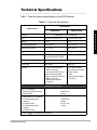
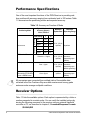
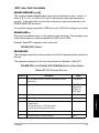
Technical Specifications .....................................................................................
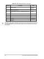
Performance Specifications................................................................................
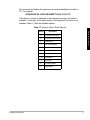
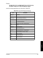
Receiver Options ................................................................................................
Option [B] RTCM Base .....................................................................................
Option [U] RTCM Remote ................................................................................
Option [E] Event Marker ...................................................................................
Option [M] Remote Monitoring..........................................................................
Option [F] Fast Data Output .............................................................................
Option [T] Point Positioning ..............................................................................
Option [3] Observables—1, 2, 3 .......................................................................
Option [J] RTK Rover .......................................................................................
Option [K] RTK Base ........................................................................................
[I] Instant RTK...................................................................................................
[G] Reserved for Future Options ......................................................................
[H] 5 Hz Synchronized RTK..............................................................................
[N] Reserved for Future Options.......................................................................
Option [Y] SBAS ...............................................................................................
..........................................................................................................................
1
2
3
4
4
6
6
6
6
6
6
7
7
7
7
7
8
8
8
8
Chapter 2 Equipment................................................................... 9
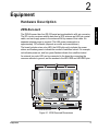
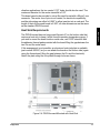
Hardware Description ......................................................................................... 9
ZXW-Eurocard.................................................................................................. 9
RF Connector ............................................................................................... 12
Antenna ........................................................................................................ 12
Power Requirements .................................................................................... 12
Environmental Specifications ....................................................................... 12
Mounting Requirements ............................................................................... 12
Heat Sink Requirements............................................................................... 13
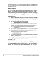
Modem Support ............................................................................................ 14
ZXW-Sensor ................................................................................................... 14
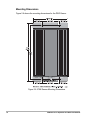
Mounting Dimensions ................................................................................... 16
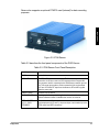
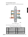
Power/Input/Output Connector ..................................................................... 17
Power Requirements .................................................................................... 18
Environmental Specifications ....................................................................... 18
RF Connector ............................................................................................... 18
Serial/Power Cable....................................................................................... 19
VII
Antenna ........................................................................................................
On-Board Battery............................................................................................
Radio Interference ..........................................................................................
Development Kits .............................................................................................
19
19
19
20
Chapter 3 Getting Started ......................................................... 25
Hardware Setup................................................................................................
Applying Power...............................................................................................
Receiver Initialization........................................................................................
Receiver Communication .................................................................................
Monitoring.........................................................................................................
Satellite Tracking ............................................................................................
Position...........................................................................................................
Setting Receiver Parameters..........................................................................
Saving Parameter Settings.............................................................................
Data Recording.................................................................................................
Default Parameters...........................................................................................
25
25
25
25
26
26
27
27
27
27
28
Chapter 4 Operation .................................................................. 33
Receiver Initialization........................................................................................
Setting Receiver Parameters............................................................................
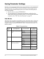
Saving Parameter Settings...............................................................................
Data Modes ....................................................................................................
Downloading the Data ....................................................................................
Data Logging through Serial Port ...................................................................
Elevation Masks .............................................................................................
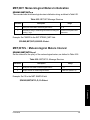
Secondary Elevation Mask ...........................................................................
Zenith Elevation Mask ..................................................................................
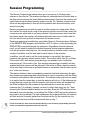
Session Programming ......................................................................................
Position Mode...................................................................................................
ALT Fix Mode ...................................................................................................
Daisy Chain Mode ............................................................................................
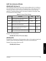
Point Positioning...............................................................................................
Remote Monitoring ...........................................................................................
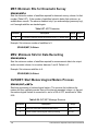
Event Marker ....................................................................................................
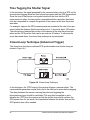
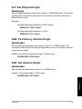
Time Tagging the Shutter Signal ....................................................................
Closed-Loop Technique (Advanced Trigger)..................................................
1PPS Out..........................................................................................................
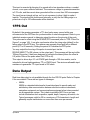
Data Output ......................................................................................................
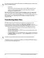
Transferring Data Files .....................................................................................
33
33
34
34
35
35
36
36
37
38
39
39
40
40
40
41
42
42
43
43
44
VIII
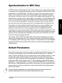
Synchronization to GPS Time ..........................................................................
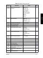
Default Parameters...........................................................................................
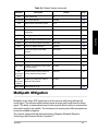
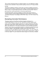
Multipath Mitigation...........................................................................................
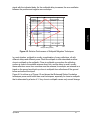
Evaluating Correlator Performance ................................................................
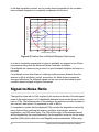
Signal-to-Noise Ratio........................................................................................
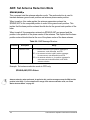
Antenna Reduction ...........................................................................................
45
45
49
50
52
53
Chapter 5 Differential and RTK Operations............................. 55
Base Stations ...................................................................................................
Setting Up a Differential Base Station ............................................................
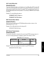
Setting Up an RTK Base Station ....................................................................
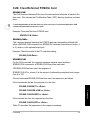
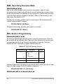
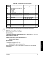
RTCM 18 & 19..............................................................................................
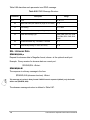
RTCM 20 & 21..............................................................................................
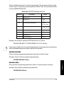
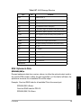
Magellan DBEN Format................................................................................
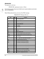
CMR or CMR Plus Format............................................................................
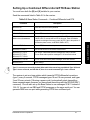
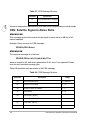
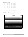
Setting Up a Combined Differential & RTK Base Station ...............................
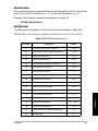
Advanced Base Station Operation .................................................................
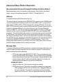
Recommended Advanced Parameter Settings for Base Stations ................
Antenna ........................................................................................................
Message Rate ..............................................................................................
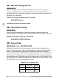
Required Differential Update Rates..............................................................
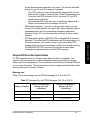
Message size..............................................................................................
Required Radio Rate ..................................................................................
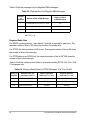
Mask Angle...................................................................................................
Base Station Position ...................................................................................
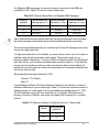
Base Station Antenna Offset ........................................................................
Using Reference Station ID ..........................................................................
Reference Station Health .............................................................................
Other RTCM Messages................................................................................
Message 2 ..................................................................................................
Filler: Message 6 Null Frame......................................................................
Special Message: Message 16...................................................................
Using a PC Interface ....................................................................................
Using a Handheld Interface ..........................................................................
Remote Stations ...............................................................................................
Setting Up a Differential Remote Station........................................................
Setting Up an RTK Remote Station................................................................
Using RTCM Messages................................................................................
Using Magellan DBN or CMR Messages .....................................................
Advanced Remote Station Operation .............................................................
Base Station Data.........................................................................................
56
56
57
57
58
59
60
61
62
62
62
62
63
63
64
66
66
67
67
67
67
67
68
68
68
68
69
69
69
69
70
71
71
IX
Base Data Latency .......................................................................................
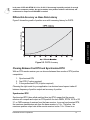
Differential Accuracy vs. Base Data Latency................................................
Chosing Between Fast RTK and Synchronized RTK ...................................
Synchronized RTK......................................................................................
Fast RTK ....................................................................................................
5 Hz Synchronized RTK .............................................................................
Position Latency .........................................................................................
Float and Fixed Solutions .............................................................................
Carrier Phase Initialization............................................................................
Reliability ....................................................................................................
Monitoring Accuracy ...................................................................................
Required Number of Satellites....................................................................
Mask Angles .................................................................................................
Auto Differential Mode ..................................................................................
RTCM Messages..........................................................................................
RTCM 104 Format, Version 2.3..................................................................
72
73
73
73
74
74
75
75
76
76
77
77
77
77
78
79
Chapter 6 Understanding RTK/CPD ......................................... 81
Monitoring the CPD Rover Solution..................................................................
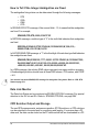
How to Tell If the Integer Ambiguities are Fixed.............................................
Data Link Monitor ...........................................................................................
CPD Solution Output and Storage..................................................................
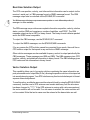
Real-time Solution Output ..............................................................................
Vector Solution Output ...................................................................................
Solution Storage .............................................................................................
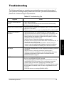
Troubleshooting................................................................................................
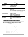
System Performance Optimization ...................................................................
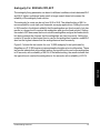
Ambiguity Fix: $PASHS,CPD,AFP .................................................................
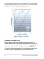
Dynamics: $PASHS,CPD,DYN ......................................................................
Fast CPD: $PASHS,CPD,FST .......................................................................
Multipath: $PASHS,CPD,MTP........................................................................
DBN Message Interval: $PASHS,CPD,PED and CPD Update Rate: $PASHS,CPD,PER ...................................................................................................
Initialization: $PASHS,CPD,RST....................................................................
Base Position Coordinates Selection: $PASHS,CPD,UBS ............................
Base Station Elevation Mask: $PASHS,ELM .................................................
Universal RTCM Base Station..........................................................................
Instant-RTK ....................................................................................................
CMR Format ...................................................................................................
Setting Up Your Receivers to Use CMR Format ..........................................
Base Receiver: ...........................................................................................
81
82
82
82
83
83
84
85
86
87
88
89
89
89
90
90
90
91
91
92
92
92
X
Rover Receiver:.......................................................................................... 92
Chapter 7 Coordinate Transformation ..................................... 93
Background ...................................................................................................... 93
Datum to Datum ............................................................................................... 94
Datum to Grid ................................................................................................... 96
Projection Types............................................................................................. 98
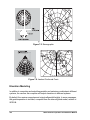
Elevation Modeling ....................................................................................... 100
Chapter 8 Command/Response Formats .............................. 103
Receiver Commands ......................................................................................
Set Commands.............................................................................................
Query Commands ........................................................................................
ALH: Almanac Messages Received .............................................................
ALT: Set Ellipsoid Height..............................................................................
ANA: Post-Survey Antenna Height...............................................................
ANH: Set Antenna Height.............................................................................
ANR: Set Antenna Reduction Mode .............................................................
ANT: Set Antenna Offsets ............................................................................
BEEP: Beeper Set-up...................................................................................
CLM: Clear/Reformat PCMCIA Card............................................................
CSN: Satellite Signal-to-Noise Ratio ............................................................
CTS: Port Protocol Setting ...........................................................................
DOI: Data Output Interval .............................................................................
DRI: Data Recording Interval........................................................................
DSC: Store Event String...............................................................................
DSY: Daisy Chain.........................................................................................
ELM: Recording Elevation Mask ..................................................................
EPG: Epoch Counter ....................................................................................
FIL,C: Close a File........................................................................................
FIL,D: Delete a File.......................................................................................
FIX: Altitude Fix Mode ..................................................................................
FLS: Receiver File Information .....................................................................
FSS: File System Status...............................................................................
HDP: HDOP Mask ........................................................................................
INF: Set Session Information........................................................................
INI: Receiver Initialization .............................................................................
ION: Set Ionospheric Model .........................................................................
ION: Query Ionospheric Parameters ............................................................
LPS: Loop Tracking ......................................................................................
105
105
105
110
111
111
111
112
113
114
115
116
117
117
118
118
118
119
120
120
120
121
121
123
124
125
127
128
128
130
XI
LTZ: Set Local Time Zone ............................................................................
MDM: Set Modem Parameters .....................................................................
MDM,INI: Initialize Modem Communication .................................................
MET: Meteorological Meters Setup .............................................................
MET,CMD: Meteorological Meters Trigger String.........................................
MET,INIT: Meteorological Meters Initialization .............................................
MET,INTVL : Meteorological Meters Interval................................................
MST: Minimum SVs for Kinematic Survey....................................................
MSV: Minimum SVs for Data Recording ......................................................
OUT,MET: Start Meteorological Meters Process .........................................
OUT, TLT: Start Tiltmeter Process ...............................................................
PAR: Query Receiver Parameters................................................................
PDP: PDOP Mask ........................................................................................
PEM: Position Elevation Mask......................................................................
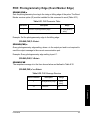
PHE: Photogrammetry Edge (Event Marker Edge) ......................................
PJT: Log Project Data ..................................................................................
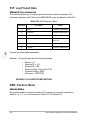
PMD: Position Mode.....................................................................................
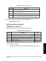
POS: Set Antenna Position ..........................................................................
POW: Battery Parameters ............................................................................
PPO: Point Positioning .................................................................................
PPS: Pulse Per Second................................................................................
PRT: Port Setting..........................................................................................
PWR: Sleep Mode ........................................................................................
RCI: Recording Interval ................................................................................
REC: Data Recording ...................................................................................
RID: Receiver ID...........................................................................................
RNG: Data Type ...........................................................................................
RST: Reset Receiver to default ....................................................................
RTR: Real-Time Error...................................................................................
SAV: Save User Parameters ........................................................................
SEM: Secondary Elevation Mask .................................................................
SES: Session Programming .........................................................................
SID: Serial Number.......................................................................................
SIT: Set Site Name.......................................................................................
SPD: Serial Port Baud Rate .........................................................................
STA: Satellite Status.....................................................................................
SVS: Satellite Selection................................................................................
TLT : Tiltmeter Set-up...................................................................................
TLT,CMD: Tiltmeter Trigger String ...............................................................
TLT,INIT : Tiltmeter Initialization...................................................................
TLT,INTVL: Tiltmeter Interval .......................................................................
131
131
133
134
134
135
135
136
136
136
137
137
140
140
141
142
142
143
144
145
145
146
147
148
148
149
150
150
151
151
152
152
156
156
156
157
158
159
159
160
160
XII
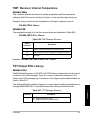
TMP: Receiver Internal Temperature ...........................................................
TST:Output RTK Latency .............................................................................
UNH: Unhealthy Satellites ............................................................................
USE: Use Satellites ......................................................................................
VDP: VDOP Mask ........................................................................................
WAK: Warning Acknowledgment..................................................................
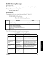
WARN: Warning Messages..........................................................................
WKN: GPS Week Number............................................................................
Raw Data Commands ....................................................................................
Set Commands.............................................................................................
Query Commands ........................................................................................
CBN: CBEN Message ................................................................................
CMR: CMR Message..................................................................................
Compact Measurement Record Packet......................................................
Observables (Message Type 0) .................................................................
L2 Data .......................................................................................................
DBN: DBEN Message ................................................................................
EPB: Raw Ephemeris .................................................................................
MBN: MBN Message ..................................................................................
OUT: Enable/Disable Raw Data Output .....................................................
PBN: Position Data.....................................................................................
RAW: Query Raw Data Parameter.............................................................
RWO: Raw Data Output Settings ...............................................................
SAL: Almanac Data ....................................................................................
SNV: Ephemeris Data ................................................................................
NMEA Message Commands ..........................................................................
Set Commands.............................................................................................
Query Commands ........................................................................................
ALL: Disable All NMEA Messages .............................................................
ALM: Almanac Message.............................................................................
CRT: Cartesian Coordinates Message.......................................................
DAL: DAL Format Almanac Message.........................................................
DCR: Delta Cartesian Message .................................................................
DPO: Delta Position Message ....................................................................
GDC: User Grid Coordinate.......................................................................
GGA: GPS Position Message.....................................................................
GLL: Latitude/Longitude Message..............................................................
GRS: Satellite Range Residuals.................................................................
GSA: DOP and Active Satellite Messages .................................................
GSN: Signal Strength/Satellite Number......................................................
GST: Pseudo-range Error Statistic Message .............................................
161
161
162
162
162
162
163
167
168
168
169
172
177
179
179
181
182
186
188
192
193
195
197
198
199
202
202
203
206
206
209
211
213
215
217
220
223
224
226
229
230
XIII
GSV: Satellites in View Message ...............................................................
GXP: Horizontal Position Message ............................................................
MSG: Base Station Message .....................................................................
NMO: NMEA Message Output Settings .....................................................
PER: Set NMEA Send Interval ...................................................................
POS: Position Message..............................................................................
PTT: Pulse Time Tag Message ..................................................................
RMC: Recommended Minimum GPS/Transit.............................................
RRE: Residual Error ...................................................................................
SAT: Satellite Status...................................................................................
TAG: Set NMEA Version ............................................................................
TTT: Event Marker......................................................................................
UTM: UTM Coordinates..............................................................................
VTG: Velocity/Course .................................................................................
XDR: Transducer Measurements ...............................................................
ZDA: Time and Date...................................................................................
RTCM Response Message Commands .........................................................
Set Commands.............................................................................................
Query Commands ........................................................................................
Query: RTCM Status ..................................................................................
AUT: Auto Differential.................................................................................
BAS: Enable Base Station..........................................................................
EOT: End of Transmission .........................................................................
INI: Initialize RTCM.....................................................................................
IOD: Ephemeris Data Update Rate ............................................................
MAX: Max Age............................................................................................
MSG: Define Message ...............................................................................
MSI: Query RTCM Message Status ...........................................................
OFF: Disable RTCM ...................................................................................
QAF: Quality Factor....................................................................................
REM: Enable Remote RTCM .....................................................................
SEQ: Check Sequence Number.................................................................
SPD: Base Bit Rate ....................................................................................
STH: Station Health....................................................................................
STI: Station ID ............................................................................................
TYP: Message Type ...................................................................................
CPD Commands.............................................................................................
Set Commands.............................................................................................
Query Commands ........................................................................................
CPD: RTK Status........................................................................................
AFP: Ambiguity Fixing ................................................................................
231
234
235
241
242
243
246
247
249
251
254
254
255
258
260
262
264
264
264
266
269
269
269
270
270
270
271
271
272
272
272
273
273
274
274
275
276
276
276
279
282
XIV
ANT: Antenna Parameters .........................................................................
CMR: CMR Received Mode .......................................................................
DLK: Data Link Status ................................................................................
DYN: Rover Dynamics................................................................................
ENT: Use Current Position .........................................................................
EOT: End of Transmission .........................................................................
FST: Fast CPD Mode .................................................................................
INF: CPD Information .................................................................................
MAX: Max Age for CPD Correction ............................................................
MOD: CPD Mode........................................................................................
MTP: Multipath ...........................................................................................
OBN: Vector Solution Information ..............................................................
OUT: Solution Output .................................................................................
PEB: Base Broadcast Interval ....................................................................
PED: DBEN/CMR Transmission Period .....................................................
PER: CPD Update Interval .........................................................................
POS: Set Base Position..............................................................................
PRO: Select RTK Format ...........................................................................
PRT: Port Output Setting............................................................................
RST: Reset CPD ........................................................................................
STS: CPD Solution Status..........................................................................
UBP: Use Base Position.............................................................................
UCT Commands.............................................................................................
DTM: Datum Selection ...............................................................................
FUM: Fix UTM Zone ...................................................................................
FZN: Set UTM Zone to Fix .........................................................................
GRD: Datum-to-Grid Transformation Selection (Map Projection) ..............
HGT: Height Model Selection .....................................................................
UDD: User-Defined Datum .........................................................................
UDG: User-Defined Datum-to-Grid Transformation ...................................
283
284
284
287
288
288
289
289
291
291
292
293
296
297
297
298
298
299
300
300
300
301
302
303
304
305
305
306
307
308
Chapter 9 SBAS Commands................................................... 313
SBA: SBAS Raw Data ..................................................................................
OUT: WAAS Almanac Data..........................................................................
SBA: Tracking Mode.....................................................................................
Automatic Mode..........................................................................................
SSO: Set SBAS Satellite Search Order........................................................
314
315
316
316
318
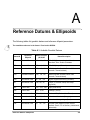
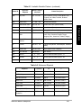
Appendix A Reference Datums & Ellipsoids......................... 319
XV
LIST OF FIGURES
Figure 2.1. ZXW-Eurocard Dimensions............................................................... 9
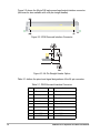
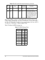
Figure 2.2. ZXW-Eurocard Interface Connector ................................................ 10
Figure 2.3. 64-Pin Straight Header Option ........................................................ 10
Figure 2.4. ZXW-Eurocard Mounted with Heat-Sink ......................................... 13
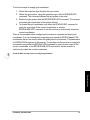
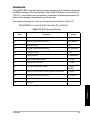
Figure 2.5. ZXW-Sensor.................................................................................... 15
Figure 2.6. ZXW-Sensor Mounting Dimensions ................................................ 16
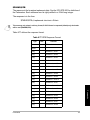
Figure 2.7. DB25 Connector.............................................................................. 17
Figure 2.8. ZXW-Sensor Serial/Power Cable .................................................... 19
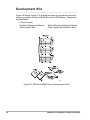
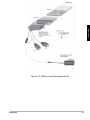
Figure 2.9. ZXW-SensorZXW-Sensor Development Kit (A) .............................. 20
Figure 2.10. ZXW-Sensor Development Kit (B)................................................. 21
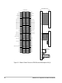
Figure 2.11. Board & Cable Pinouts for ZXW-Eurocard Development Kit (A)... 22
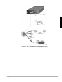
Figure 2.12. ZXW-Eurocard Development Kit (B) ............................................. 23
Figure 4.1. Secondary Elevation Mask (SEM) Zone ......................................... 36
Figure 4.2. ZEN (Zenith) Elevation Mask Zone ................................................. 37
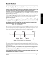
Figure 4.3. Event Marker Time Measurement ................................................... 41
Figure 4.4. Closed Loop Technique .................................................................. 42
Figure 4.5. Relative Performance of Multipath Mitigation Techniques .............. 51
Figure 4.6. Detailed View of Multipath Mitigation Performance......................... 52
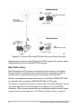
Figure 5.1. Combined Differential/RTK Base Station and Remote Operation... 72
Figure 5.2. DGPS Accuracy .............................................................................. 73
Figure 6.1. Ambiguity Fix Test Results.............................................................. 88
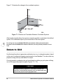
Figure 7.1. Rotation and Translation Between Coordinate Systems................. 96
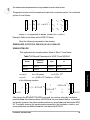
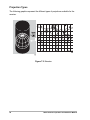
Figure 7.2. Mercator .......................................................................................... 98
Figure 7.3. Transverse Mercator ....................................................................... 99
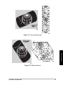
Figure 7.4. Oblique Mercator............................................................................. 99
Figure 7.5. Stereographic ................................................................................ 100
Figure 7.6. Lambert Conformal Conic ............................................................. 100
XVI
LIST OF TABLES
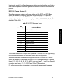
Table 1.1. Technical Specifications ..................................................................... 3
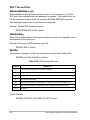
Table 1.2. Accuracy as Function of Mode ........................................................... 4
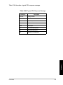
Table 1.3. Remote User’s Guide Options ............................................................ 5
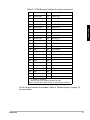
Table 2.1: ZXW-Eurocard Interface Connector ................................................. 10
Table 2.2: ZXW-Sensor Front Panel Description .............................................. 15
Table 2.3: ZXW-Sensor DB25 Connector Pinout .............................................. 17
Table 3.1: Default Values .................................................................................. 28
Table 4.1. Recording Modes ............................................................................. 34
Table 4.2. File Types ......................................................................................... 35
Table 4.3. Position Modes ................................................................................. 39
Table 4.4. Default Values .................................................................................. 46
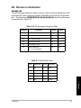
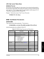
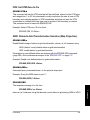
Table 5.1. Differential Base Station Commands ............................................... 56
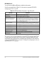
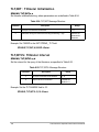
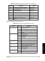
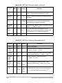
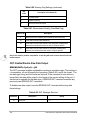
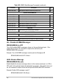
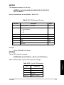
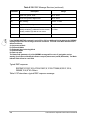
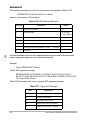
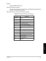
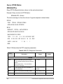
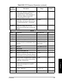
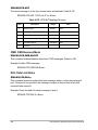
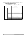
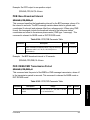
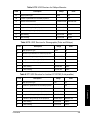
Table 5.2. RTK Base Station Commands - Types 18 and 19 ........................... 57
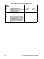
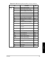
Table 5.3. RTK Base Station Commands - Types 20 and 21 ........................... 58
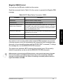
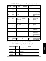
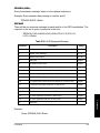
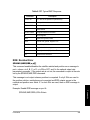
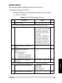
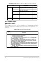
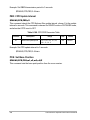
Table 5.4. RTK Base Station Commands - DBEN ............................................ 59
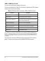
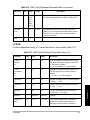
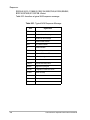
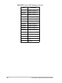
Table 5.5. RTK Base Station Commands - CMR or CMR Plus Format ............ 60
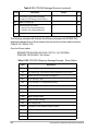
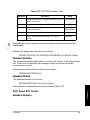
Table 5.6. Base Station Commands - Combined Differential and RTK ............ 61
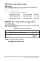
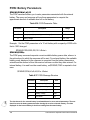
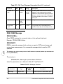
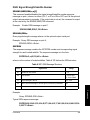
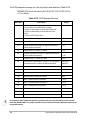
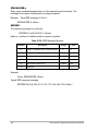
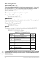
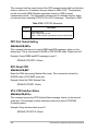
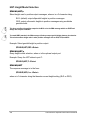
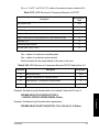
Table 5.7. Message Size for RTCM Messages 18 & 19 or 20 & 21 .................. 63
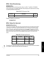
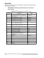
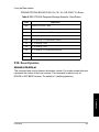
Table 5.8. Message Size For Magellan DBN Messages ................................... 64
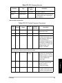
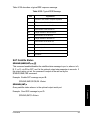
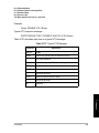
Table 5.9. Minimum Baud Rates for RTCM Messages 18 & 19 or 20 & 21 ...... 64
Table 5.10.Minimum Baud Rates for Magellan DBN Messages ....................... 65
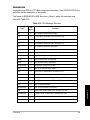
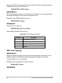
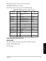
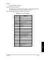
Table 5.11.Maximum Number of Satellites Above a 4° Mask Angle ................. 65
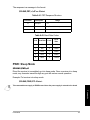
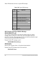
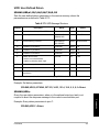
Table 5.12.Differential Remote Station Commands .......................................... 69
Table 5.13.RTK Remote Station Command ...................................................... 70
Table 5.14.RTK Remote Station Commands .................................................... 71
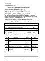
Table 5.15.Auto Differential Modes and Position Output ................................... 78
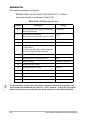
Table 5.16.RTCM Message Types .................................................................... 79
Table 6.1. Troubleshooting Tips ........................................................................ 85
Table 6.2. CPD optimization commands ........................................................... 86
Table 6.3. Default RTCM Message Schedules ................................................. 91
Table 6.4. Percentage of Ambiguity Initialization Using a Single Epoch ........... 92
Table 7.1. User Coordinate Transformation Functionalities .............................. 94
Table 7.2. Ellipsoid Parameters for WGS-72 and WGS-84 ............................... 95
Table 8.1. Command Parameter Symbols ...................................................... 104
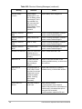
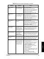
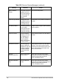
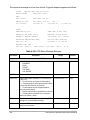
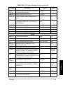
Table 8.2. Receiver Commands ...................................................................... 106
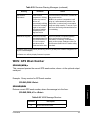
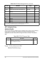
Table 8.3. ALH Parameter Table ..................................................................... 110
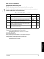
Table 8.4. ANR Message Structure ................................................................. 112
Table 8.5. Antenna Offsets Settings ................................................................ 113
Table 8.6. ANT Message Structure ................................................................. 114
Table 8.7. CLM Message Structure ................................................................. 116
XVII
Table 8.8. CSN Message Structure ................................................................. 116
Table 8.9. DSY Parameter Table .................................................................... 118
Table 8.10.FIX Parameter Settings ................................................................. 121
Table 8.11.FLS Message Structure ................................................................. 122
Table 8.12.Typical FLS Message .................................................................... 123
Table 8.13.FSS Message Structure ................................................................ 124
Table 8.14.INF Parameter Table ..................................................................... 125
Table 8.15.INF Message Structure .................................................................. 126
Table 8.16.INI Parameter Description Table ................................................... 127
Table 8.17.Baud Rate Codes .......................................................................... 127
Table 8.18.Reset Memory Codes .................................................................... 128
Table 8.19.ION Message Structure ................................................................. 129
Table 8.20.LPS Message Structure ................................................................. 130
Table 8.21.MDM Setting Parameters and Descriptions .................................. 131
Table 8.22.Baud Rate Codes .......................................................................... 132
Table 8.23.MDM Message Structure ............................................................... 133
Table 8.24.MET,CMD Message Structure ....................................................... 134
Table 8.25.MET,INIT Message Structure ........................................................ 135
Table 8.26.MET,INTVL Message Structure ..................................................... 135
Table 8.27.MST Parameter ............................................................................. 136
Table 8.28.OUT,MET Message Structure ....................................................... 136
Table 8.29.OUT,TLT Message Structure ........................................................ 137
Table 8.30.PAR Parameter Table .................................................................. 138
Table 8.31.PHE Parameter Table ................................................................... 141
Table 8.32.PHE Message Structure ................................................................ 141
Table 8.33.PJT Parameter Table .................................................................... 142
Table 8.34.PMD Parameter Table ................................................................... 143
Table 8.35.POS Parameter Table ................................................................... 143
Table 8.36.POW Parameter Table .................................................................. 144
Table 8.37.POW Message Structure ............................................................... 144
Table 8.38.PPO Parameter Table ................................................................... 145
Table 8.39.PPS Message Structure ................................................................ 145
Table 8.40.PPS Response Structure ............................................................... 146
Table 8.41.PRT Response Structure ............................................................... 147
Table 8.42.Baud Rate Codes .......................................................................... 147
Table 8.43.REC Message Structure ................................................................ 148
Table 8.44.RID Message Structure ................................................................. 149
Table 8.45.RNG Data Modes .......................................................................... 150
Table 8.46.RTR Message Structure ................................................................ 151
Table 8.47.SES,PAR Message Structure ........................................................ 152
Table 8.48.SES,SET Message Structure ........................................................ 153
XVIII
Table 8.49.SES Message Structure ................................................................ 154
Table 8.50.SSN Message Structure ................................................................ 155
Table 8.51.SPD Baud Rate Codes .................................................................. 156
Table 8.52.STA Message Structure ................................................................ 158
Table 8.53.TLT,CMD Message Structure ........................................................ 159
Table 8.54.TLT,INIT Message Structure ......................................................... 160
Table 8.55.TLT,INTVL Message Structure ...................................................... 160
Table 8.56.TMP Message Structure ................................................................ 161
Table 8.57.TST Message Structure ................................................................. 161
Table 8.58.WARN Message Structure ............................................................ 163
Table 8.59.Receiver Warning Messages ......................................................... 163
Table 8.60.WKN Message Structure ............................................................... 167
Table 8.61.Raw Data Types and Formats ....................................................... 170
Table 8.62.Raw Data Commands ................................................................... 170
Table 8.63.CBN Message Structure (ASCII Format) ...................................... 172
Table 8.64.Solution Type Flag Table (ASCII Format) ..................................... 173
Table 8.65.CBN Message Structure (Binary Format) ...................................... 174
Table 8.66.Solution Type Flag Structure (Binary Format) ............................... 175
Table 8.67.Compact Measurement Record Structure ..................................... 178
Table 8.68.Compact Measurement Record Packet Definition ......................... 179
Table 8.69.CMR Type 0 Message Header ...................................................... 179
Table 8.70.CMR Type 0 Message Observables Block .................................... 180
Table 8.71.CMR Type 0 Message Observables Block (L2) ............................ 181
Table 8.72.RPC Message Structure ................................................................ 182
Table 8.73.RPC Packed Parameter Descriptions ........................................... 183
Table 8.74.DBEN Message Sizes ................................................................... 184
Table 8.75.BPS Message Structure ................................................................ 185
Table 8.76.BPS Status Byte Definition ............................................................ 186
Table 8.77.EPB Response Format .................................................................. 187
Table 8.78.MPC Measurement Structure (Binary Format) .............................. 189
Table 8.79.MPC Message Structure (ASCII Format) ...................................... 190
Table 8.80.Warning Flag Settings ................................................................... 191
Table 8.82.OUT Message Structure ................................................................ 192
Table 8.81.Measurement Quality (Good/Bad Flag) ......................................... 192
Table 8.83.PBN Message Structure (ASCII Format) ....................................... 194
Table 8.84.PBN Message Structure (Binary Format) ...................................... 195
Table 8.85.RAW Message Structure ............................................................... 196
Table 8.86.RWO Message Structure ............................................................ 198
Table 8.87.ALM Message Structure ................................................................ 199
Table 8.88.SNV Message Structure ............................................................... 200
Table 8.89.NMEA Data Message Commands ................................................. 205
XIX
Table 8.90.ALM Response Message .............................................................. 207
Table 8.91.Typical ALM Response Message .................................................. 208
Table 8.92.CRT Message Structure ................................................................ 209
Table 8.93.DAL Message Structure ................................................................ 212
Table 8.94.Typical DAL Message .................................................................... 213
Table 8.95.DCR Message Structure ................................................................ 214
Table 8.96.DPO Message Structure ................................................................ 216
Table 8.97.GDC Message Structure ............................................................... 217
Table 8.98.Typical GDC Response Message ................................................. 219
Table 8.99.GGA Message Structure ............................................................... 220
Table 8.100.Typical GGA Message ................................................................. 222
Table 8.101.GLL Message Structure ............................................................... 223
Table 8.102.Typical GLL Message .................................................................. 224
Table 8.103.GRS Message Structure .............................................................. 225
Table 8.104.Typical GRS Message ................................................................. 226
Table 8.105.GSA Message Structure .............................................................. 227
Table 8.106.Typical GSA Message ................................................................. 227
Table 8.107.GSN Message Structure .............................................................. 229
Table 8.108.Typical GSN Message ................................................................. 230
Table 8.109.GST Message Structure .............................................................. 231
Table 8.110.GSV Message Structure .............................................................. 232
Table 8.111.Typical GSV Message ................................................................. 232
Table 8.112.GXP Message Structure .............................................................. 234
Table 8.113.Typical GXP Message ................................................................. 235
Table 8.114.Common Fields of Type 1, 2, 3, 6, 16, 18, 19, 20 and 21 ........... 237
Table 8.115.Remainder of Type 1 Message ................................................... 237
Table 8.116.Remainder of Type 2 Message ................................................... 238
Table 8.117.Remainder of Type 3 Message ................................................... 238
Table 8.118.Remainder of Type 16 Message ................................................. 238
Table 8.119.Remainder of Type 18 and 20 Messages .................................... 239
Table 8.120.Remainder of Type 19 and 21 Messages .................................... 240
Table 8.121.NMO Message Structure ............................................................. 242
Table 8.122.POS Message Structure .............................................................. 244
Table 8.123.Typical POS Message ................................................................. 245
Table 8.124.PTT Message Structure ............................................................... 246
Table 8.125.Typical PTT Response Message ................................................. 247
Table 8.126.RMC Message Structure ............................................................. 247
Table 8.127.Typical RMC Response ............................................................... 249
Table 8.128.RRE Message Structure .............................................................. 250
Table 8.129.Typical RRE Message ................................................................. 251
Table 8.130.SAT Message Structure .............................................................. 252
XX
Table 8.131.Typical SAT Message .................................................................. 252
Table 8.132.NMEA Message Format Codes ................................................... 254
Table 8.133.$PASHR,TTT Message Structure ............................................... 255
Table 8.134.UTM Message Structure .............................................................. 256
Table 8.135.Typical UTM Response Message ................................................ 257
Table 8.136.VTG Message Structure .............................................................. 258
Table 8.137.Typical VTG Message ................................................................. 259
Table 8.138.XDR Message Structure .............................................................. 261
Table 8.139.ZDA Message Structure .............................................................. 262
Table 8.140.Typical ZDA Response Message ................................................ 263
Table 8.141.RTCM Commands ....................................................................... 265
Table 8.142.RTC Response Parameters ........................................................ 266
Table 8.143.EOT Parameters .......................................................................... 269
Table 8.144.RTC,MSI Message Structure ....................................................... 271
Table 8.145.Available Bit Rate Codes ............................................................. 273
Table 8.146.RTC,STH Health of Base Station ................................................ 274
Table 8.147.RTC,TYP Message Types ........................................................... 275
Table 8.148.CPD Commands .......................................................................... 278
Table 8.149.CPD Status Message Structure ................................................... 280
Table 8.150.CPD,AFP Parameter Table ......................................................... 282
Table 8.151.CPD,ANT Parameter Table ......................................................... 283
Table 8.152.CPD,ANT Message Structure ...................................................... 284
Table 8.153.CPD,DLK Message Structure ...................................................... 285
Table 8.154.CPD,DLK Response Message Example - Rover Station ............ 286
Table 8.155.CPD,DLK Response Message Example - Base Station .............. 287
Table 8.156.CPD,DYN Parameter Table ......................................................... 288
Table 8.157.CPD,EOT Parameter Table ......................................................... 288
Table 8.158.INF Message Structure ................................................................ 289
Table 8.159.CPD,MOD Parameter Table ........................................................ 291
Table 8.160.CPD,MOD Message Structure .................................................... 292
Table 8.161.MTP Parameter Table ................................................................. 293
Table 8.162.OBEN Message Structure (Binary Format) ................................. 294
Table 8.163.CPD,OUT Parameter Table ......................................................... 296
Table 8.164.CPD,PEB Parameter Table ......................................................... 297
Table 8.165.CPD,PED Parameter Table ......................................................... 297
Table 8.166.CPD,PER Parameter Table ......................................................... 298
Table 8.167.CPD,POS Parameter Table ......................................................... 299
Table 8.168.CPD,PRO Parameter .................................................................. 300
Table 8.169.CPD,STS Message Structure ...................................................... 301
Table 8.170.CPD,UBP Parameter Table ......................................................... 301
Table 8.171.UCT Commands .......................................................................... 303
XXI
Table 8.172.UDD Message Structure .............................................................. 307
Table 8.173.UDG Structure for Equatorial Mercator ....................................... 308
Table 8.174.UDG Structure for Transverse Mercator ...................................... 308
Table 8.175.UDG Structure for Oblique Mercator ........................................... 309
Table 8.176.UDG Structure for Stereographic (Polar and Oblique) ................ 309
Table 8.177.UDG Structure for Lambert CC SPC83 (2 std parallels) ............. 309
Table 8.178.UDG Structure for Lambert Conic Conformal for SPC27 ............ 310
Table 8.179.UDG Structure for Transverse Mercator for SPC27 .................... 311
Table 8.180.UDG Structure for Transverse Mercator SPC27 Alaska Zone 2-9 311
Table 9.1. Summary of WAAS Commands ..................................................... 313
Table 9.2. SBA,DAT Parameters .................................................................... 314
Table 9.3. WAAS Almanac Structure .............................................................. 315
Table A.1. Available Geodetic Datums ............................................................ 319
Table A.2. Reference Ellipsoids ....................................................................... 321
XXII
1
Introduction
Overview
This manual provides operation and reference information for the ZXW-Sensor and
the ZXW-Eurocard. These two receivers are intended specifically for real-time
industrial applications, such as machine control in construction, mining, and precision
agriculture; as well as precision navigation applications such as docking and dredging.
Both configurations are built to withstand the extremely high vibration requirements in
their target application. The receivers also provide positions at the very high updates
and low latencies required in control applications.
The ZXW-Receivers can track two SBAS (WAAS/EGNOS/MSAS) satellites
simultaneously on two channels. In addition, the ZXW-Receivers track all the available
signals from GPS satellites, both C/A and P code, both L1 and L2 frequencies,
whether or not AS (“Anti-Spoofing” or encryption) is on or off. The benefit of a dualfrequency receiver is that it is excellent for RTK (Real Time Kinematic) applications,
especially on longer baselines. RTK is typically used where centimeter position
accuracy is required in real time.
Because this manual describes both the ZXW-Sensor and the ZXW-Eurocard, the term “ZXWReceiver” is used to refer to both products except where noted otherwise.
Introduction
1
Functional Description
The ZXW-Receiver is activated when power is applied to the power
connector, and (in the case of the ZXW-Sensor) the power switch is ON. After
self-test, the receiver initializes its 12x3 channels and begins searching for all
GPS space vehicles (SV) within the field of view of the antenna.
As the ZXW-Receiver acquires (locks onto) each SV, it notes the time and
then collects the ephemeris data about the orbit of that SV, and almanac data
about the orbits of all the SVs in the constellation.
The ZXW-Receiver features 12-parallel channel/12-SV all-in-view operation;
each of up to 12 visible SVs can be assigned to a channel and then
continuously tracked. Each GPS SV broadcasts almanac and ephemeris
information every 30 seconds, and the receiver automatically records this
information in its non-volatile memory.
The receiver has an L1/L2-band radio frequency (RF) port and four RS-232
serial input/output (I/O) ports. Ports A, B, and C are capable of two-way
communication with external equipment. On the Sensor, port D is not
available. On the Eurocard, port D can be accessed via the DIN64 connector.
The RF circuitry receives satellite data from a GPS antenna and LNA via a
coaxial cable, and can supply +5V to the antenna/LNA by means of that
cable. No separate antenna power cable is required. Typical power
consumption is approximately 7.5 watts even when powering an LNA.
The receiver incorporates a red/green LED which lights red to indicate power
status, and flashes green to indicate the number of locked satellites.
The ZXW-Receiver collects Coarse Acquisition (C/A) code-phase (pseudorange) and full wavelength carrier phase measurement on L1 frequency
(1575 MHz), Precise (P) code phase (pseudo-range) and full wavelength
carrier phase on L1 and L2 frequency (1227 MHz). The ZXW-Receiver
permits uninterrupted use even when anti-spoofing (AS) is turned on. When
AS is on, the ZXW-Receiver automatically activates Magellan’s patented Ztracking mode that mitigates the effects of AS. The performance when AS is
on is the same as when AS is off.
2
ZXW-Receivers Operation and Reference Manual
Technical Specifications
Table 1.1 lists the technical specifications of the ZXW-Receiver.
Table 1.1. Technical Specifications
Specifications
Characteristic
ZXW-Sensor
Equipment Description
Tracking
ZXW-Eurocard
12 channels L1 CA/PL1 and PL2
Size
2.30”H x 6.75”W x 10.31”L
0.6”H x 3.9”W x 6.8”L
Weight
3.75 lb
0.5 lb
Operating temperature
-30° to +55°C
-30° to +70°C*
Storage temperature
-40° to +85°C
-40° to +85°C
Humidity
100%
95% non-condensing
Environment
Resistant to wind-driven rain
and dust per MIL-STD-810E
N/A
Power consumption
7.5 watts
Power input
10 to 28VDC
5VDC ±5%
Interface
• Three RS-232 ports via a
DB-25 connector
(one internal RS-232 port)
• One antenna connector
• Event marker and 1PPS via
DB-25 connector
• Optional radio antenna
connector
•
•
•
•
•
Four RS-232 ports
One antenna connector
Event marker
1PPS
Optional radio interface
connector
Measurement Precision
C/A (>10° elevation)
• Pseudo-range (raw/smooth)
• Carrier Phase
P-Code AS off (>10° elevation)
• L1 Pseudo-range (raw/
smooth)
• L1 Carrier Phase
• L2 Pseudo-range (raw/
smooth)
• L2 Carrier Phase
•25cm/3.6cm
•0.9mm
•15cm/0.9cm
•0.9mm
•21cm/1.3cm
•0.9mm
* Refer to @@@ for heat sinking information.
Equipment Description
3
Performance Specifications
One of the most important functions of the ZXW-Receiver is providing realtime position with accuracy ranging from centimeter level to 100 meters. Table
1.2 summarizes the positioning modes and expected accuracy.
Table 1.2. Accuracy as Function of Mode
Typical Horizontal
Accuracy (2drms),
5 SVs, PDOP<4
Positioning Mode
Vertical
Autonomous
Horizontal
PPO setting:
Maximum
Update Rate
Y
N
50%
0.63
1.47
95%
1.49
3.26
Sigma
0.72
1.88
50%
0.36
1.89
95%
1.78
5.95
Sigma
0.93
3.01
5 Hz (10 Hz
optional)
Anywhere
1.0 meters + 10 ppm
5 Hz (10 Hz
optional)
Several hundred
kilometers
(depending upon
datalink)
5mm + 1ppm
5 Hz (10 Hz
optional)
Several hundred
kilometers
(depending upon
satellite geometry)
RTCM code differential
Static (post-processed)
Real-time carrier phase
differential in RTCM-RTK
format or DBEN format
Maximum
Operating Range
1.6cm +2ppm
5 Hz (10 Hz
optional
<15 kilometers
(depending upon
datalink)
All accuracies were computed from multiple trials of live satellite data
collected in the San Francisco Bay area with receivers and survey grade
antennas under average multipath conditions.
Receiver Options
Table 1.3 lists the available options. Each option is represented by a letter or
number presented in a certain order. You can verify the installed options by
issuing the following command to the receiver using an external handheld
controller or PC, as described in chapter 6, Command/Response Formats:
$PASHQ,RID
4
ZXW-Receivers Operation and Reference Manual
The command will display the options on an external handheld controller or
PC. For example:
$PASHR,RID,UZ,30,ZE24,BUEXMFT3JKI-H-Y,1A01*5C
If the letter or number is displayed in the response message, the option is
available. Conversely, if the letter/number is not displayed, the option is not
available. Table 1.3 lists the available options.
Table 1.3. Remote User’s Guide Options
Equipment Description
Description
B
RTCM differential base
U
RTCM differential remote
E
Event Marker
X
External Frequency
M
Remote monitor option
F
Fast Data Output
T
Point Positioning
1,2,3
Equipment Description
Option
Observables
J
RTK Rover
K
RTK Base Station
Y
SBAS Option
5
Option [B] RTCM Base
The receiver has the ability to be set as an RTCM differential base station and
can output real-time differential corrections when this option is enabled.
The output will be in RTCM-104, Version 2.3 format message types 1,3,6, 16
and 22 as well as RTCM Carrier Differential 18, 19, 20, and 21. For messages
18, 19, 20, and 21, the J option is also required.
Option [U] RTCM Remote
Real-time differential corrections are available when this option is enabled.
The receiver will decode the RTCM-104, Version 2.3 format message types
1,3,6,9, 16, and 22 as well as types 18, 19, 20 and 21. For messages 18, 19,
20, and 21, the J option is also required.
Option [E] Event Marker
The [E] option enables the storage of event times created from a trigger
signal. The receiver measures and records event times with high accuracy
(down to one microsecond). The receiver stores an event time at the rising
edge of the trigger signal (or the falling edge on command) and the time is
recorded in the receiver’s PC memory card and/or output through the TTT
NMEA message.
Option [M] Remote Monitoring
The remote monitoring option allows you to use the REMOTE.EXE to access
and control the receiver via a modem from a remote location.
Option [F] Fast Data Output
This option enables the receiver to be programmed to output both raw
position data and NMEA messages at user-selectable frequencies up to
10Hz. Without this option, only frequencies up to 5Hz are available.
Option [T] Point Positioning
The [T] option allows you to put the receiver into point positioning mode using
the $PASHS,PPO command. Point positioning mode improves the accuracy
of an autonomous position of a static point.
6
ZXW-Receivers Operation and Reference Manual
Option [3] Observables—1, 2, 3
This option determines the observables available in the receiver where:
1—CA code and P-code on L1/L2 (no carrier)
2—CA code and carrier, P-code on L1/L2 (no carrier)
3—CA code and carrier, P-code on L1/L2 and carrier
Option [J] RTK Rover
Equipment Description
The [J] option allows the receiver to act as a rover station that utilizes the
carrier phase differential (both DBEN and RTCM message 18, 19, 20, and 21)
data transmitted from the base to compute differentially corrected positions.
This option requires the observables option to be 3.
For RTCM messages type 18, 19, 20, and 21, the U option is required in
addition to the J option.
Option [K] RTK Base
The [K] option allows the receiver to act as an RTK base station which outputs
carrier phase differential data. This option requires the observables option to
be 3. For RTCM 18/19 or 21/22, the B option is also required.
[I] Instant RTK
The [I] option, an extension of the J option, allows the receiver to use the RTK
system - Instant RTKTM which uses a data processing strategy for integer
ambiguity initialization. The initialization time using Instant RTK typically
requires a single epoch of data if there are 6 or more satellites available with
reasonable open sky and low multipath. The baseline length should be 7 km
or less.
[G] Reserved for Future Options
Equipment Description
7
[H] 5 Hz Synchronized RTK
The [H] option enables the receiver to output synchronized or matched time
tag RTK positions at a rate up to 5 Hz (5 positions per second); 5 Hz
synchronized RTK lets you attain the better accuracy of matched time tag
RTK with nearly the same productivity as Fast CPD. This feature is available
only when using DBEN or CMR format data.
[N] Reserved for Future Options
Option [Y] SBAS
The [Y] option allows SBAS raw data messages, SBAS almanac messages,
and the commands to enable any of the SBAS tracking modes. SBAS
(Satellite Based Augmentation System) includes WAAS, EGNOS and MSAS.
Where appearing, WAAS may refer to SBAS, EGNOS and MSAS.
8
ZXW-Receivers Operation and Reference Manual
2
Equipment
Hardware Description
ZXW-Eurocard
The board includes a two-color LED; the LED lights red to indicate the power
status, and flashes green to indicate the number of satellites locked. For example,
red indicates power on, and four green flashes indicate four satellites locked.
An external two-color LED can be connected to the board by connecting the
common cathode to ground, and the anodes to the LED-GRN and LED-RED pins.
Figure 2.1. ZXW-Eurocard Dimensions
Equipment
9
Equipment
The ZXW-Eurocard has four RS-232 serial ports embedded in a 64-pin connector.
The RF circuitry receives satellite data from a GPS antenna and LNA via coaxial
cable, and can supply power to the antenna/LNA by means of that cable. No
separate antenna power is required. The LNA power consumption is
approximately 150 milliwatts (depends on model and manufacturer).
Figure 2.2 shows the 64-pin DIN male power/input/output interface connector
(this board is also available with a 64-pin straight header).
Figure 2.2. ZXW-Eurocard Interface Connector
Figure 2.3. 64-Pin Straight Header Option
Table 2.1 defines the pinout and signal designations of the 64-pin connector.
Table 2.1: ZXW-Eurocard Interface Connector
Pin
10
Code
Pin
Code
A1
GND
B1
GND
A2
+5 Vdc input
B2
+5 Vdc input
A3
—*
B3
SSR +12 V
A4
LNA GND
B4
LNA power†
A5
—
B5
LED red
A6
—
B6
LED green
A7
Serial GND
B7
Serial A DCD
A8
Serial A DTR
B8
Serial A DSR
A9
Serial A TXD
B9
Serial A CTS
ZXW-Receivers Operation and Reference Manual
Table 2.1: ZXW-Eurocard Interface Connector (continued)
Pin
A10
Code
Pin
Code
B10
Serial A RTS
A11
Serial C TXD
B11
Serial C CTS
A12
Serial C RXD
B12
Serial C RTS
A13
Serial D TXD
B13
Serial D CTS
A14
Serial D RXD
B14
Serial D RTS
A15
Serial GND
B15
—
A16
—
B16
—
A17
Serial B TXD
B17
Serial B CTS
A18
Serial B RXD
B18
Serial B RTS
A19
—
B19
Radio LED - red
A20
—
B20
Radio LED - green
A21
GND
B21
—
A22
GND
B22
1 PPS output
A23
GND
B23
—
A24
GND
B24
Photo input
A25
GND
B25
—
A26
GND
B26
—
A27
GND
B27
—
A28
GND
B28
Manual reset input‡
A29
GND
B29
—
A30
GND
B30
—
A31
GND
B31
—
A32
GND
B32
—
Equipment
Serial A RXD
* “—” means no connection.
† Required only if LNA requires greater than 5Vdc.
‡Short to ground with a switch closure or open-collector transistor.
Port A can be connected to a modem. Refer to “Modem Support” on page 14
for more details.
Equipment
11
RF Connector
The RF connector is a standard 50-ohm SMB female wired for connection via
coaxial cabling to a GPS antenna with integral LNA. The SMB connector shell
is connected to the ZXW-Eurocard common ground. The SMB center pin
provides +5Vdc to power the LNA (maximum 150 mA draw) and accepts 1227
and 1575 MHz RF input from the antenna; the RF and DC signals share the
same path.
For installations compatible with the GG24-Eurocard, an SMB-to-SMA
adapter is available (part number 730188).
Antenna
The ZXW-Eurocard provides DC power on the center conductor for an LNA
on the antenna cable. No external source is required to power a 5 Vdc LNA.
An LNA requiring greater than 5 Vdc may be used by connecting an external
power supply to LNA POWER and LNA GND on the 64-pin connector. No
jumpering is required as long as the voltage is higher than 5 Vdc. The
maximum external LNA voltage should not exceed 15Vdc.
The gain of the LNA less the loss of the cable and connectors should be
between 20 and 45 dB. Connect the antenna cable directly to the antenna
connector on the ZXW-Eurocard. Antenna cables exceeding 15 dB of loss
require a line amplifier. A line amp (part number 700389) compensates for 20
dB of cable loss. The line amplifier has N-type connectors to connect to the
antenna cable.
Power Requirements
The ZXW-Eurocard requires 5 Vdc regulated ±5% at the board connector, and
consumes 4.0 watts.
Environmental Specifications
The operating temperature range of the ZXW-Eurocard is -30°C to +70°C;
storage temperature is -40°C to +85°C.
The operating humidity range is 0 to 95%, non-condensing.
The ZXW-Eurocard is designed to operate while being subjected to random
vibration per MIL-STD-810E Method 514.4, as well as a machine control
vibration test of 5g for 20 hours in each orthogonal axis.
Mounting Requirements
The ZXW-Eurocard should be mounted using, as a minimum, the four 0.110”
holes in the corners of the board, on standoffs as described under the heatsink requirements (refer to “Heat Sink Requirements” on page 13). In high-
12
ZXW-Receivers Operation and Reference Manual
vibration applications, the two center 0.110” holes should also be used. The
maximum diameter for the center standoffs is 3/16”.
This board can also be provided in a true Eurocard format with a 96-pin 3-row
connector. The center row of pins is not loaded, for electrical compatibility,
and the side edges are milled to 0.062” to allow insertion into a card rack. The
length of the true Eurocard board is 6.300”; all other dimensions are the same
as the standard ZXW-Eurocard.
Heat Sink Requirements
Equipment
The ZXW-Eurocard has one large quad-flat-pack IC on the bottom side that
requires a heat sink to keep it within its safe operating temperature range. If
you wish to mount the board inside a metal case, use 0.200” standoffs with
the adhesive thermal pads provided with the board filling the gap between the
two ICs and the metal case.
If this arrangement is not possible, an aluminum heat-sink plate is available
(part number 200541) so you can attach the board on the bottom side (again
using the thermal pad) filling the gap between the ICs and the heat-sink).
Attach the plate using the four plated-through holes as shown.
Figure 2.4. ZXW-Eurocard Mounted with Heat-Sink
Equipment
13
Applications requiring 70°C operation should provide either a substantial heat
sink or forced-air cooling to limit the temperature rise on the board to less than
10°C above ambient.
Modem Support
The ZXW-Eurocard can be interfaced to a modem through Port A. Refer to
Table 2.1 and the modem user manual before making connections. After
making connections, you can follow the steps below to configure and initialize
the modem using ZX receiver commands. If using a modem other than US
Robotics, refer to modem command (MDM) in the user manual for more
detailed information.
1. Select an appropriate baud rate for Port A and modem; the baud rate
should be identical for Port A and the modem. You may have to refer
to the user manual if selecting a baud rate other than the default.
2. Set Port A for modem use with the command
$PASHS,MDM,ON,A,O,[baud rate].
The baud rate field in the command is optional, as indicated by the
brackets. The above command can be sent through serial ports B, C,
or D. The receiver acknowledges with the response message
$PASHR,ACK.
3. Use the query command $PASHQ,MDM to verify the setting in step 2.
4. Send command $PASHS,MDM,INI to initialize the modem. The
receiver should respond with the message
$PASHR,MDM,INI,OK
5. The modem connected to Port A of the receiver is now initialized and
ready for communication.
6. To establish a communication link, the modem on the other end has
to dial the modem connected to the receiver.
ZXW-Sensor
The sensor version of the receiver, Figure 2.5, has three RS-232 input/output
(I/O) ports embedded in a DB25 connector (ports A,B, and C are available to
the user), an L1/L2-band RF port, and an optional radio RF port. The ZXW-
14
ZXW-Receivers Operation and Reference Manual
Sensor also supports an optional PCMCIA card (internal) for data recording
purposes.
Equipment
Figure 2.5. ZXW-Sensor
Table 2.2 describes the front panel components of the ZXW-Sensor.
Table 2.2: ZXW-Sensor Front Panel Description
Component
Equipment
Function
RADIO connector
Not Available.
GPS ANT connector
The GPS ANT connector is a standard TNC female receptacle wired for
connection via 50-ohm coax to a GPS antenna with an integral LNA.
The connector shell is connected to the ZXW-Sensor common ground.
The TNC center pin provides +5Vdc to power the LNA, and accepts
1227 and 1575 MHz RF input from the antenna; RF and DC signals
share the same path.
ON/OFF switch
Turns the unit on and off.
PWR/SATS LED
Flashing red indicates power is applied to the receiver. Number of green
flashes indicates number of satellites the receiver is locked to.
SERIAL PORTS
A, B, C, PWR
STROBES
The multi-function 25-pin connector serves as the three RS-232 serial
input/output ports (A, B, and C), the power input, event marker input, the
1PPS output, and LED connectors.
15
Mounting Dimensions
Figure 2.6 shows the mounting dimensions for the ZXW-Sensor.
Figure 2.6. ZXW-Sensor Mounting Dimensions
16
ZXW-Receivers Operation and Reference Manual
Power/Input/Output Connector
Figure 2.7 shows the pin arrangement for the DB25 power/input/output
connector.
Equipment
Figure 2.7. DB25 Connector
Table 2.3 lists the signal designations for the DB25 connector.
Table 2.3: ZXW-Sensor DB25 Connector Pinout
Pin
Equipment
Code
Pin
Code
1
LED RED
14
LED GND
2
LED GREEN
15
1PPS OUT
3
GND
16
CTSC-clear to send, port C
4
RTSC-ready to send, port C
17
RXDC-receive data, port C
5
TXDC-transmit data, port C
18
RXDB-receive data, port B
6
TXDB-transmit data, port B
19
EVENT IN
17
Table 2.3: ZXW-Sensor DB25 Connector Pinout (continued)
Pin
Code
Pin
Code
7
GND
20
CTSB-clear to send, port B
8
RTSB-ready to send, port B
21
RXDA-receive data, port A
9
TXDA-transmit data, port A
22
No connection
10
GND
23
CTSA-clear to send
11
RTSA-ready to send, port A
24
EXT PWR 1
12
GND
25
EXT PWR 2
13
GND
Power Requirements
The ZXW-Sensor requires 10-28 Vdc and consumes 7.5 watts.
Environmental Specifications
The operating temperature range of the Z-Sensor is -30°C to +55°C; storage
temperature range is -40°C to +85°C.
The ZXW-Sensor will work at 100% humidity and is rated to MIL-STD-810E
for wind driven rain and dust.
RF Connector
The RF connector is a standard 50-ohm female TNC wired for connection via
coaxial cabling to a GPS antenna with integral LNA. The TNC connector shell
is connected to the Z-Sensor common ground. The TNC center pin provides
+5 Vdc to power the LNA (maximum 150 mA draw) and accepts 1227 and
1575 MHz RF input from the antenna; the RF and DC signals share the same
path.
18
ZXW-Receivers Operation and Reference Manual
Serial/Power Cable
The serial/power cable, Figure 2.8, connects the ZXW-Sensor to the power
source, the PC or handheld unit, and any peripherals.
Equipment
Figure 2.8. ZXW-Sensor Serial/Power Cable
Antenna
The ZXW-Sensor provides DC power on the center conductor for the antenna
cable to provide power to the LNA. Antenna/LNA gain minus RF network (RF
cable and connectors) loss should be between +20 and +30 dB.
On-Board Battery
Both the ZXW-Sensor and ZXW-Eurocard contain a 3.6V lithium backup
battery to maintain power to the non-volatile memory and real-time clock
when the main power source is not available. This battery should last a
minimum of 5 years. The firmware monitors the battery voltage, and detects a
failure when it reaches 2.25 volts. You can obtain this information via any
serial port with the $PASHQ,WARN command (refer to “WARN: Warning
Messages” on page 163 for detailed information about this command).
Radio Interference
Some radio transmitters and receivers, such as FM radios, can interfere with
the operation of GPS receivers. Before setting up your project, Magellan
recommends you verify that nearby handheld or mobile communications
devices do not interfere with the ZXW-receivers.
Equipment
19
Development Kits
Figure 2.9 through Figure 2.12 illustrate the items you should have received
with your purchase of either the ZXW-Eurocard or ZXW-Sensor. These items
are listed below.
(This document)
Evaluate Software and Manual
Antenna and Cable
Mission Planning Software & Manual
Power Supply and Interface Cables
Figure 2.9. ZXW-SensorZXW-Sensor Development Kit (A)
20
ZXW-Receivers Operation and Reference Manual
Equipment
Figure 2.10. ZXW-Sensor Development Kit (B)
Equipment
21
CABLE ASSEMBLY PINOUT
DB37
BOARD PINOUT
GND
B1
A1
GND
+5V INPUT
B2
A2
+5V INPUT
22
30
SSR +12v
B3
A3
NC
LNA POWER
B4
A4
LNA GND
LED RED
B5
A5
NC
LED GREEN
B6
A6
NC
20
SERIAL A DCD
B7
A7
SERIAL GND
2
SERIAL A DSR
B8
A8
SERIAL A DTR
21
SERIAL A CTS
B9
A9
SERIAL A TXD
3
SERIAL A RTS
B10
A10
SERIAL A RXD
CASE
SERIAL C CTS
B11
A11
SERIAL C TXD
SERIAL C RTS
B12
A12
SERIAL C RXD
SERIAL D CTS
B13
A13
SERIAL D TXD
SERIAL D RTS
B14
A14
SERIAL D RXD
NC
B15
A15
SERIAL GND
NC
B16
A16
NC
SERIAL B CTS
B17
A17
SERIAL B TXD
4
SERIAL B RTS
B18
A18
SERIAL B RXD
23
RADIO LED RED
B19
A19
NC
5
RADIO LED GREEN
B20
A20
NC
NC
B21
A21
GND
1 PPS OUTPUT
B22
A22
GND
NC
B23
A23
GND
PHOTO INPUT
B24
A24
GND
NC
B25
A25
GND
NC
B26
A26
GND
11
1
PORT A
DSRA
PUR
DTRA
BLU
DCDA
GRN
GND
RED
5
CTSA
GRN
7
TXDA
YEL
RTSA
BRN
RXDA
BLK
SHIELD
6
4
1
2
8
3
CASE
9
NC
PORT B
24
6
CASE
GND
RED
CTSB
GRN
TXDB
WHT
RTSB
BRN
RXDB
BLK
SHIELD
5
7
2
8
3
CASE
1
4
6
NC
B27
A27
GND
MANUAL RESET INPUT
B28
A28
GND
NC
B29
A29
GND
NC
B30
A30
GND
NC
B31
A31
GND
NC
B32
A32
GND
NC
8
+
9
BACKUP BATTERY
LOCATED INSIDE DB37
29
10
7
26
POWER
CONNECTOR
Figure 2.11. Board & Cable Pinouts for ZXW-Eurocard Development Kit (A)
22
ZXW-Receivers Operation and Reference Manual
Equipment
Figure 2.12. ZXW-Eurocard Development Kit (B)
Equipment
23
24
ZXW-Receivers Operation and Reference Manual
3
Getting Started
This chapter describes receiver operations.
Hardware Setup
Perform the following steps before turning on the receiver:
1. Connect the antenna cable from the GPS antenna to the antenna
connector on the receiver.
2. Connect supplied power cable to the power connector on the receiver.
Getting Started
3. Connect serial port connectors of serial/power cable to appropriate
connectors on external equipment.
Applying Power
Apply power after your equipment has been properly cabled.
Receiver Initialization
It is good practice to reset your receiver prior to operating it for the first time or
when a system malfunction occurs. A reset of the internal memory clears the
memory and restores the factory defaults. Send the following command:
$PASHS,INI,5,5,5,5,1,0
Receiver Communication
After you have the receiver powered and running, you must send it commands in
order to receive data. The following procedure describes how to send commands
to and receive information from the receiver using an IBM-compatible PC. Many
communication software packages, such as the Magellan Evaluate or Receiver
Communications Software, allow you to interface with the receiver. Evaluate
includes a communications package that automatically establishes
communication with the receiver and allows you to send commands from a
predefined menu, as well as tools for logging and playback of data, graphical
display of position and velocity, and data analysis.
Getting Started
25
The default communications parameters of the receiver are:
•
•
•
•
9600 baud
8 data bits
no parity
one stop bit
When first establishing communication, your interface must use this protocol.
Having established communication, you may send commands.
All the default data output commands are set to NO. The receiver will not
output any data until you send a message commanding it to do so.
If you have typed in and sent the command correctly, you should receive a
response. To become familiar with receiver messages, send a few common
commands and observe the responses.
Monitoring
The receiver provides the capability of monitoring receiver activity while data
collection is occurring. The following is a step-by-step instruction of how to
access important receiver status information such as:
•
•
•
Satellite Tracking
Position
Remaining Memory
Satellite Tracking
If you wish to monitor the satellites the receiver is tracking and using for
position solutions, perform the following steps:
1. Send the NMEA command $PASHS,NME,SAT,x,ON
x—port designation
ON—turns port on
2. SAT messages will be output every second through the designated
port.
3. The response message contains the number of tracked satellites as
well as whether individual satellites are used in the position solution.
26
ZXW-Receivers Operation and Reference Manual
Position
To view the current position of the Z-receiver, perform the following steps:
1. Send the NMEA command $PASHS,NME,POS,x,ON.
x—port designation
ON—turns port on
2. POS messages are output every second through the designated port.
3. The response message contains information about the current
position of the receiver.
Setting Receiver Parameters
Getting Started
If you do not wish to use the factory default settings, you must change each
setting individually. Refer to the Command/Response Formats chapter in this
manual.
Saving Parameter Settings
Ordinarily, Z-receiver parameters that have been changed will return to their
default status after a power cycle. The Z-receiver allows you to save changed
settings so they will be saved through a power cycle. Perform the following
steps to save receiver settings:
1. Send the command $PASHS,SAV,c. This command enables or
disables user parameters in memory, where c is Y (yes) or N (no).
User parameters that were changed prior to issuing the SAV
command are saved until commands INI or RST are issued, or until
SAV is set to No and a power cycle occurs.
Data Recording
Recording data directly onto your PC can be done with GBSS Software which
can be purchased from your dealer or Regional Sales Manager. Alternatively,
you can use the internal PCMCIA card (optional) in the ZXW-Sensor for
recording data. See “REC: Data Recording” on page 148.
Getting Started
27
Default Parameters
During the normal course of receiver operation, you will often change one or
more receiver parameters such as recording interval, port baud rate, or
elevation mask. To save new settings, you must save the current setting to
memory or else all parameters (with a few exceptions) will be reset to the
default values during a power cycle. The exceptions are session
programming parameters, modem setting parameters, MET (meteorological)
and TLT (tilt) parameters, and the POW (power) parameters. Saving
parameters can be done by issuing a $PASHS,SAV,Y command to a serial
port. When parameters are saved to the memory, they are maintained until a
memory reset or a receiver initialization is performed which resets all
parameters to their default.
Figure 3.1 lists the default values of all user parameters.
Table 3.1: Default Values
Parameter
Default
SVS
SV tracking selection
Y for all
PMD
Position mode selection
0
Altitude Hold Fix Mode Selection
0
FIX
PEM
Position elevation mask
10
Zenith position elevation mask
90
FUM
Use of UTM coordinates
N
FZN
UTM zone selection
01
ZEN_PEM
28
Description
PDP
Position Dilution of Precision mask
40
HPD
Horizontal Dilution of Precision mask
04
VDP
Vertical Dilution of Precision mask
04
UNH
Use of unhealthy SV’s
N
ION
Enable ionosphere model
N
PPO
Enable point positioning mode
N
SAV
Save parameters in battery backup memory
N
ANR
Antenna noise reduction
CPD
LAT
Antenna latitude
00N
LON
Antenna longitude
00W
ALT
Antenna altitude
+00000.000
DTM
Datum selection
W84
ZXW-Receivers Operation and Reference Manual
Table 3.1: Default Values (continued)
Parameter
Description
Default
Datum user-defined parameters
Semi major axis = 6378137
Inverse flattening =
298.257224
Remaining parameters = 0
PHE
Photogrammetry edge selection
R
PPS
Pulse per second default parameters
Period= 1 second
Offset = 000.0000
Edge = R
POW
parameters
Power capacity of external battery
All 0’S
Session
Programming
Session Programming Default Parameters
INUSE flag = N
REF day = 000
OFFSET = 00:00
For all Sessions:
Session Flag = N
Start Time = 00:00:00
End Time = 00:00:00
RCI = 20
MSV = 3
ELM = 10
RNG = 0
MDM
Modem Parameters
MODE=OFF
TYPE = 0 (US Robotics)
PORT = B
BAUD RATE = 38400
BEEP
Warning beep
Off
CTS
Clear to send port setting
On
LPS
Loop parameter setting
01, 2, 3
MET
meteorological parameter setting
All ports off
INIT-STR:No
TRIG-CMD:*0100P9
INTVL:5
TLT
Tilt Meter parameter setting
All ports OFF
INIT-STR:No
TRIG-CMD:*0100XY
INTVL:1
NMEA
messages
NMEA Message Output Status
OFF in all ports
TAG
NMEA message format
ASH
PER
NMEA Messages Output Rate
001.0
RCI
Raw Data Output Rate
020.0
Getting Started
Getting Started
UDD
29
Table 3.1: Default Values (continued)
Parameter
DOI
30
Description
Default
Data output interval
20
DRI
Data recording interval
20
MSV
Minimum Number of SV’s for Raw Data Output
03
ELM
Elevation Mask for Raw Data Output
10
ZEN_ELM
Zenith elevation mask
90
REC
Record Data Flag (N/A)
E
MST
Minimum Number of SV’s for Kinematic
Operation
0
ANH
Antenna Height (before session)
00.0000
ANA
Antenna Height (after session)
00.0000
SIT
Site ID Name
????
EPG
Kinematic Epoch Counter
000
RNG
Ranger Mode Selection (N/A)
0
RAW data
Raw Data Output Status
OFF in all ports
Raw data
format
Raw Data Output Format
ASCII in all ports
Serial Port
Baud Rate
Serial Ports Baud Rate Selection
9600 in all ports
RTCM MODE
RTCM Differential Mode Selection
OFF
RTCM PORT
RTCM Differential Mode Port Selection
A
AUT
Automatic differential/autonomous switching
when RTCM differential mode enabled
N
RTCM SPD
RTCM differential bps speed setting
0300
STI
RTCM base or remote station id setting
0000
STH
RTCM base station health setting
0
MAX
Maximum age for old RTCM corrections to be
used
0060
QAF
RTCM communication quality setting
100
SEQ
Use sequence number of RTCM correction in
remote station
N
TYPE
RTCM differential messages enabled and output
frequency of the enabled messages
1 = 01, 6 = OFF, remaining
messages 00
RTCM EOT
End of character selection for RTCM corrections
CRLF
MSG
Text for RTCM type 16 message
empty
IOD
IODE update rate
30
CPD MODE
CPD mode selection
Disabled
ZXW-Receivers Operation and Reference Manual
Table 3.1: Default Values (continued)
Parameter
Description
Default
PED
DBEN output transmission period
DBEN PORT
Output port for DBEN messages in the base
B
CPD EOT
End of character selection for CPD corrections
CRLF
AFP
Setting of ambiguity fixing confidence level
099.0
MAX AGE
Maximum age of corrections for CPD
30
DYN
CPD rover mode dynamic operation
WALKING
POS Output
001.0
CPD
MTP
Level of multipath selection
MEDIUM
CPD POS
Reference position of the other receiver
RECEIVED
Fast CPD Mode Selection
ON
CPD PER
CPD Update Interval
01
CKR
Reserved
ON
IAF
Reserved
ON
ANT radius
Radius of the Antenna
0.0000
ANT offset
Distance from Antenna Phase Center to Antenna
Edge
00.0000
ANT
horizontal
azimuth
Azimuth measured from Reference Point to
Antenna Phase Center
00000.00
ANT
horizontal
distance
Distance from Reference Point to Antenna Phase 00.0000
Center
SBAS mode
SBAS mode on or off
Getting Started
Getting Started
FST
Off
31
32
ZXW-Receivers Operation and Reference Manual
4
Operation
This chapter describes receiver operations other than those available through the
front panel.
Receiver Initialization
It is good practice to reset your receiver prior to operating it for the first time or when a
system malfunction occurs. A reset of the internal memory clears the memory and
restores the factory defaults. This reset does not affect data stored on the PCMCIA
card. Send the following command to execute the initialization:
$PASHS,INI,5,5,5,5,1,0
For more information about this command, refer to Chapter 8, Command/Response
Formats.
Setting Receiver Parameters
All user parameters may be set or changed by sending commands to the receiver
serial port. Refer to Chapter 8, Command/Response Formats for more information
about these commands.
Operation
33
Saving Parameter Settings
Ordinarily, receiver parameters that have been changed will return to their default status
after a power cycle. The Z-Family of receivers allows you to save changed receiver
settings so they will be saved through a power cycle. Perform the following steps to
save receiver settings:
1. Send the receiver command: $PASHS,SAV,Y.
2. This command saves any parameters that have been modified from their
default values before the command is issued. For more information about this
command, refer to “SAV: Save User Parameters” on page 151.
Data Modes
The receiver can record data in three different modes, called data modes or data types.
Each mode records different combination of data records and can only be changed
using the serial port command $PASHS,RNG. Table 4.1 describes these modes. The
default is mode 0.
Table 4.1. Recording Modes
Recording
Mode
0
2
4
34
Typical Application
Records Created
Raw data, full code and carrier
phase
Position data only
Raw data, full code and carrier
phase, position data file
File Type After
Conversion
Raw data
B-file
Ephemeris
E-file
Session information
S-file
Almanac
ALMyy.ddd
Position
C-file
Session
S-file
Almanac
ALMyy.ddd
Raw data
B-file
Position
C-file
Ephemeris
E-file
Session information
S-file
Almanac
ALMyy.ddd
ZXW-Receivers Operation and Reference Manual
Downloading the Data
The data on the PC card can be either downloaded from the receiver via the serial port
or read from the PCMCIA drive into the PC. In both cases, use the Download
application. Download handles the protocol required to transfer data from the receiver
via the serial port into the PC memory.
Table 4.2. File Types
File Type
Generated From
Format
B-file
Raw data - generally code and carrier phase, position, and SITE data
Binary
E-file
Satellite ephemeris data
Binary
S-file
Site information data
ASCII
C-file
Position data
ASCII
M-file
Event marker files (photogrammetry)
ASCII
D-file
Site attribute files
ASCII
Almanac data
Binary
ALMyy.ddd
Data Logging through Serial Port
An alternative way to record data is to record data directly onto your PC. This method
is useful if your data card does not have enough space or if you wish to bypass the
download process. To record data directly onto the PC, use the GBSS Software which
can be purchased from your dealer or Regional Sales Manager.
Operation
35
Operation
When transferring PC data from the receiver or the PCMCIA drive into the PC,
Download reads the U-files records from the PC card and converts them into different
data files, creating one set of data files per each session. Data files are named using
the U-file name for that session, however the first letter corresponds to the file type.
The one exception are almanac files which are named ALMyy.ddd where YY are the
last two digits of the year and ddd is the day of the year. Table 4.2 lists the file types.
Elevation Masks
Because data from GPS satellites near the horizon are often excessively noisy and
can degrade position computation and post-processing , GPS receivers use elevation
masks to filter out the unwanted signals. The receiver has 2 main elevation masks, a
data elevation mask and a position elevation mask. Data for satellites below the data
recording elevation mask will not be recorded or output. Satellite data below the
position elevation mask will not be used for position computation.
The default for both the data elevation mask and the position elevation mask is 10
degrees. The data elevation mask may be changed using the $PASHS,ELM
command. The position elevation mask may be changed using the $PASHS,PEM
command. For receivers with an LED display, the data elevation mask may also be
changed in the Survey Configuration (SurvConf) menu setting the ELEV MASK:
parameter.
Secondary Elevation Mask
In some cases, noisy atmospheric conditions may exist at higher elevations only in a
certain sector of the sky, interfering with satellite data in that part so that position
quality is degraded. For example, ionospheric activity may be especially active to the
north, affecting all satellites in that quadrant. To correct this problem, a secondary
elevation mask has been created. This secondary elevation mask is set using the
command $PASHS,SEM. The parameters for the $PASHS,SEM include a first and a
second azimuth that are used to define the part of the sky to be masked, and an
elevation mask value that applies only to the area within those azimuth values (Figure
4.1). Note that the $PASHS,SEM command only applies to position computation and
does not affect data recording or output.
N
PEM=20
300o
PEM=10
o
60
Figure 4.1. Secondary Elevation Mask (SEM) Zone
36
ZXW-Receivers Operation and Reference Manual
Zenith Elevation Mask
Towers or other heavy metal equipment that are directly over the GPS antenna may
cause intermittent data collection and areas of extreme multipath at very high
elevation angles, creating poor quality data from certain satellites and degrading
position computation. To remove these satellites, a zenith elevation mask has been
created. Whereas the normal elevation mask disregards satellites between the
horizon and the mask angle, the zenith elevation mask ignores satellites between the
mask angle and the zenith (90 ο), as shown in Figure 4.2. Rather than create a
separate command, an additional, optional zenith elevation mask parameter has been
added to the $PASHS,ELM data elevation mask and the $PASHS,PEM position
elevation mask commands.
Operation
Circular patch of sky
masked by zenith mask
Zenith mask angle
Zenith 90o
Zenith mask angle
Horizon
0
o
180
o
Figure 4.2. ZEN (Zenith) Elevation Mask Zone
Operation
37
Session Programming
The Session Programming feature allows you to pre-set up to 26 observation
sessions in the receiver. The receiver can then run unattended and will collect data on
the data card only during the times that have been preset. Once set, the sessions will
collect data during the preset session times every day. Or if desired, a session time
offset can be programmed in that will shift the session start and end times by a set
amount every day.
Session programming can also be used to put the receiver into sleep mode. When
the receiver is in sleep mode, most of the receiver functions are shut down which will
conserve power when data is not being collected. Using the session start times that
have been preset, the receiver will automatically wake up in time to collect data for
the next session and go back to sleep when the session is over.
Session programming is enabled by using either Receiver Communications Software
or the REMOTE.EXE program, with either the <ALT-P> option, or else by sending the
$PASHS,SES commands through the serial port. Regardless of which method is
used, you will need to enable the individual sessions and set session parameters
such as the desired start/stop time, the recording interval, elevation mask, minimum
number of satellites, and the data type for each session to be recorded.
In addition, you will need to set the mode (session in use switch), the session
reference day, and any desired session offset. The mode is either Yes, No, or Sleep.
If the mode is NO, then session programming is not enabled, even if individual
session are set. If the mode is Yes, then session programming is enabled, and any
enabled individual sessions will be activated. If the mode is Sleep, then the receiver
will go into sleep mode once an activated session is completed, and will wake up just
prior to the next session.
The session reference day is a mandatory parameter that both determines the start
day of session programming data collection and is used in conjunction with the Offset
to determine the session start and end times. The reference day must be set to equal
to or earlier than the current day, or else the sessions will not run. If the reference day
is later than the current day, then the session start and end times will decrement by
the Offset multiplied by the numbers of days between the current day and the
reference day. For example, suppose you wish to collect data every day for 7 days
observing the identical satellite window on each day. Since the GPS window moves
backwards 4 minutes per day, you would set the Offset to 0400 and set the reference
day equal to the current day. For each subsequent day of data collection, all sessions
will start and end 4 minutes earlier than the previous day. By the seventh day, the
sessions will start and end 28 minutes earlier than on day 1.
If a file name with the same name and session ID as the current session programming session ID
exists, new data will be appended to the end of this file.
38
ZXW-Receivers Operation and Reference Manual
Position Mode
The receiver performs a position fix computation in four modes. The $PASHS,PMD
command is used to select the mode. Table 4.3 describes these four modes.
Table 4.3. Position Modes
Description
0
At least four satellites with elevation equal to or above elevation mask are needed to compute a
position. All three polar coordinates are computed in this mode.
1
At least three satellites with elevation equal to or above position elevation mask are needed to
compute a position. Only latitude and longitude are computed if three satellites are locked and
altitude is held. If more than three satellites are locked, this mode is similar to mode 0.
2
At least three satellites with elevation equal to or above position elevation mask are needed to
compute a position. Only latitude and longitude are computed, and altitude is always held,
regardless of number of satellites.
3
At least three satellites with elevation equal to or above position elevation mask are needed to
compute a position. Only latitude and longitude are computed, and altitude is held if only three
satellites are locked. If more than three satellites are used and HDOP is less than the specified
HDOP mask, all three polar components are computed. If HDOP is higher than the specified
HDOP mask, receiver automatically goes into altitude hold mode.
ALT Fix Mode
Two modes define what altitude is selected when the receiver is in altitude hold mode.
The $PASHS,FIX command can be used to select between these modes.
In mode 0, the most recent altitude is used. This is either the one entered by using the
$PASHS,ALT command or the one computed when four or more satellites are used in
the solution, whichever is most recent. If the last altitude is the one computed with four
or more satellites, it is used only if VDOP is less than the VDOP mask.
In mode 1, only the last altitude entered is used in the position fix solution.
On initial power-up, or a receiver initialization, the most recent antenna altitude is 0.
Operation
39
Operation
Mode
Daisy Chain Mode
The Daisy Chain mode establishes a communication link through the GPS receiver,
between a PC/handheld and a peripheral device. When the GPS receiver is in Daisy
Chain mode, all commands entered in one serial port are passed back out through
another serial port. The commands are not interpreted by the GPS receiver. The
command $PASHS,DSY enables the Daisy Chain mode and allows the user to
assign which serial ports to be used. A typical example of the use of Daisy Chain
mode is communicating with a radio through a handheld. The radio and handheld are
not directly connected but are both connected to the GPS receiver via separate serial
ports. By enabling the Daisy Chain mode between the two serial ports used by the
handheld and radio, the handheld can communicate with the radio through the GPS
receiver. Refer to “DSY: Daisy Chain” on page 118.
Point Positioning
The Point Positioning option improves the accuracy of a stand-alone absolute
position of a stationary receiver from about 50 meters to less than five meters over a
period of four hours, and can typically get down to a couple meters level after ten
hours. Point positioning uses an averaging technique to reduce the effects of
Selective Availability (SA) and other fluctuating errors. Point positioning mode can be
set using the $PASHS,PPO command. Refer to Chapter 8, Command/Response
Formats for more details about this command. The Point Positioning receiver option
[T] must be set in the receiver for this command to work.
Remote Monitoring
Remote monitoring allows a user to control a remotely located receiver through a PC
and a modem link. You can then:
•
•
•
monitor operational status
configure receiver parameter settings
download data
This function is useful in situations where a receiver is operating in a difficult to
access location.
The receiver must have the Remote Monitor [M] option enabled. Use the
REMOTE.exe software to perform remote monitoring.
40
ZXW-Receivers Operation and Reference Manual
Event Marker
When the Event Marker [E] option is installed, the receiver can measure and record
event times with high accuracy. In order to store an event time in the receiver’s
memory, a trigger signal must be applied to the appropriate connector located on the
rear panel of the receiver (refer to your individual receiver manual for pinout
information). The event marker feature allows the event time to be stored in memory
and downloaded using the DOWNLOAD program as an M-file, or output by using the
$PASHS,NME,TTT command.
The measured time is accurate down to 1 microsecond. This is GPS time (UTC + 13
seconds as of 1 January, 1999) and is recorded as the time since the start of the GPS
week (00:00 a.m. Sunday). The output includes day number, hours, minutes, seconds,
and fractional seconds up to seven digits. With each event time, the receiver also
records the site name. One example of the record is:
TEXA 4 21:30:19:4309643
The event time is measured relative to the receiver's GPS time. It measures only the
first event during the period between 2 GPS epochs (1ms). Refer to Figure 4.3. This
allows use of mechanical switches without concern for contact bounces.
Figure 4.3. Event Marker Time Measurement
The receiver stores only one event time per nav processing cycle (0.1 sec). If more
than one event time is measured within a data collection period, the receiver records
only the first one.
The trigger pulse may be TTL-compatible or open collector. Minimum pulse duration is
100 nanoseconds when the signal is not terminated at the receiver input. The
impedance is approximately 2K ohms.
Use a coaxial cable with BNC connectors to connect the camera trigger output to the
photogrammetry input connector of the sensor.
Operation
41
Operation
At the rising or falling edge (selectable) of the trigger signal, the time is recorded in the
receiver’s PC card. The trigger signal can be set to the falling edge using the
$PASHS,PHE command.
Time Tagging the Shutter Signal
In this technique, the signal generated by the camera shutter is fed to a GPS unit for
accurate time-tagging which can then be post-processed with the GPS observations.
Since the time of the picture is not synchronized with the time that the GPS
measurement is taken, the two position computations before and after the shutter
time are interpolated to compute the position of the camera at the time the picture
was taken.
For example, suppose the GPS measurements are recorded at the rate of one per
second while the distance that the aircraft moves in ½ second is about 100 meters.
The induced error between the position of the camera at the time the picture was
taken and the GPS position fixes can be as much as 50 meters. To minimize the
errors discussed above, the closed loop technique is recommended.
Closed-Loop Technique (Advanced Trigger)
The closed-loop technique combines PPS synchronization and shutter timing as
shown in Figure 4.4.
Figure 4.4. Closed Loop Technique
In this technique, the 1PPS output of the receiver triggers a camera shutter. The
camera shutter generates a signal that is fed to the receiver for accurate time tagging.
The delay between the camera receiving the pulse and triggering the
photogrammetry port should be calculated. This may then be applied so as to
advance the 1PPS from the receiver so that the shutter time exactly matches the
GPS system time for the epoch. No interpolation between the shutter time and the
GPS position time will be needed.
42
ZXW-Receivers Operation and Reference Manual
This input is asserted by bringing it to ground with a low-impedance driver, a contact
closure, or an open-collector transistor. The maximum voltage to guarantee assertion
is 0.75 volts, and the current when grounded will be no more than 350 microampere.
The input has an internal pull-up, so it is not necessary to drive it high to make it
inactive. The signal will be de-bounced internally, so only the first falling edge in a
pulse train of up to 100 milliseconds will be detected.
1PPS Out
You may output the time tag of the pulse to a serial port via the
$PASHS,NME,PTT,c,ON (where c is the output port). This message will be sent within
100ms of the pulse. It has been designed to minimize the latency when the offset is
0.0 (within 30ms of the pulse when Fast CPD is off).
This output is driven by a 3.3 volt CMOS gate through a 150 ohm resistor, and is
intended to drive a high-impedance TTL or CMOS input. The minimum allowable input
resistance to guarantee TTL input levels is 250 ohms.
Data Output
Real time data output is only available through the four RS-232 ports. Refer to Chapter
6 for more details. There are two types of messages:
•
NMEA
NMEA is a standard data transfer format developed to permit ready and
satisfactory data communication between electronic marine instruments,
navigation equipment and communications equipment when interconnected
via an appropriate system. This is data in printable ASCII form and may
include information such as position, speed, depth, frequency allocation, etc.
Typical messages might be 20 to a maximum of 79 characters in length and
generally require transmission no more often than once per second.
Operation
43
Operation
By default, the receiver generates a TTL-level pulse every second within one
microsecond of the GPS time for synchronization of external equipment. Refer to your
individual receiver manual to determine signal location on the pinouts of the ports.
This pulse can be offset using the $PASHS,PPS command (refer to “PPS: Pulse Per
Second” on page 145). It can also synchronize either the rising edge (default) or the
falling edge to the GPS time. The receiver can generate this signal with a different
period (0.1 to 60 seconds). Setting the period to 0 disables the PPS pulse.
Due to the extra resolution required for RTK operation, some NMEA messages are actually longer
than the specified 80 characters.
•
Proprietary
When specific information was needed, and the NMEA standard did not
contain a suitable message, Magellan created proprietary messages.
Messages are available in ASCII.
With the Fast Data output [F] option installed, the highest output rate supported is
10Hz. This is valid for every setting except for RTK Differential mode, if Fast CPD
mode is set to off, in which case the highest rate is 1 Hz (if Fast CPD mode is on, 10
HZ is available). Also, if the [F] option is not installed, the highest output rate
supported is 5Hz.
Transferring Data Files
GPS data stored on the PC Card may be transferred to a computer for postprocessing by three different methods using Download. Download reads the
session file (U-file), converts the file into the different data files (B-, C-, D-, E-, M-, S, and almanac files), and transfers the converted files to the specified directory.
•
•
•
Download data directly through one of the receiver serial ports into any
directory on the computer.
Load the PCMCIA card into a PCMCIA drive and download the data to any
directory on the computer.
Load the PCMCIA card into a PCMCIA drive in your computer, and copy the
file MICRO_Z.BIN to your hard disk. Then use Download to convert the file
into usable data files.
The U-file is a compressed file format and is not usable until converted using Download.
A Standalone version of Download is available in the Software/GPSToolKit folder on
our ftp site at ftp://ftp.magellangps.com.
44
ZXW-Receivers Operation and Reference Manual
Synchronization to GPS Time
All GPS receivers contain internal clocks. These clocks are of varying quality, and for
cost reasons, are not generally accurate enough to be precisely synchronized to GPS
system time (or “true GPS time”). The effect of receiver clock error shows up in two
places. First, it affects the instant in time when measurement snapshots are taken,
and second, it introduces errors in the values of the measurements themselves. This
means that two receivers at the same location (zero-baseline), but with different clock
errors, will, among other things, provide different position measurements. Similarly, if
two receivers are moving together, their position measurements would be different,
because each receiver will report a position for a snapshot taken at a different time.
The receiver offers a GPS Time Sync Mode, which almost completely removes the
effects of the receiver clock error. For example, the jumps in the raw measurements
do not appear in GPS Time Sync Mode, and also in zero baseline tests, two Magellan
receivers in GPS Time Sync Mode will provide very closely matching pseudo-range
measurements.
Default Parameters
During the normal course of receiver operation, a typical user will often change one or
more receiver parameters such as recording interval, port baud rate, or elevation
mask. To save new settings, the user must save the current setting to memory or else
all parameters (with a few exceptions) will be reset to the default values during a
power cycle. The exceptions are session programming parameters, modem setting
parameters, MET (meteorological) and TLT (tilt) parameters, and the POW (power)
parameters. To save parameters to memory, issue the $PASHS,SAV,Y command via
the serial port. When parameters are saved to the memory, they are maintained until a
memory reset or a receiver initialization is performed which will reset all parameters
back to their default.
Only the parameters modified prior to issuing the SAV command are saved in memory. Any
parameter modified after SAV is issued reverts to default after power cycle.
Operation
45
Operation
Fortunately, if a receiver obtains measurements from four or more satellites it can
determine its own internal clock error. In order to reduce the effects mentioned
previously, most receivers use the computed clock error to periodically reset the
internal receiver clock to remain close to GPS system time (within a millisecond). This
method does not entirely remove the effects mentioned above and furthermore causes
jumps in the raw measurements obtained by the receiver; all of which the user must
account for when processing the data.
The following table lists the default values of all user parameters.
Table 4.4. Default Values
Parameter
Default
Page
SVS
Satellite Tracking Selection
Y for all
151
PMD
Position Mode selection
0
142
Altitude Hold Fix Mode selection
0
121
Position Elevation Mask
10
140
Zenith position elevation mask
90
140
FUM
Use of UTM coordinates
N
304
FZN
UTM Zone selection
01
305
PDP
Position Dilution of Precision mask
40
140
HPD
Horizontal Dilution of Precision mask
04
124
VDP
Vertical Dilution of Precision mask
04
162
UNH
Use of Unhealthy satellite’s
N
162
ION
Enable Ionosphere model
N
128
PPO
Enable Point Positioning mode
N
145
SAV
Save parameters in battery backup
memory
N
151
ANR
Antenna noise reduction
CPD
112
LAT
Antenna latitude
00N
142
LON
Antenna longitude
00W
143
ALT
Antenna altitude
+00000.000
111
DTM
Datum selection
W84
303
UDD
Datum user-defined parameters
Semi-major Axis = 6378137.000
Inverse flattening = 298.257224
Remaining parameters = 0
307
HGT
Height model selection
ELG
306
GRD
Datum-to-grid transformation selection
NON
305
PHE
Photogrammetry edge selection
R
141
PPS
Pulse-per-second default parameters
Period = 1 second
Offset = 000.0000
Edge = R
145
Power capacity of external battery
ALL 0’S
144
FIX
PEM
ZEN_PEM
POW
parameters
46
Description
ZXW-Receivers Operation and Reference Manual
Table 4.4. Default Values (continued)
Parameter
Description
Session
Session programming default
Programming parameters
Default
Page
152
MDM
Modem parameters
MODE=OFF
TYPE = 0 (US Robotics)
PORT = B
BAUD RATE = 38400
131
BEEP
LED display and warning beep
Off (ZXW-Sensor)
114
CTS
Clear to send port setting
On
117
LPS
Loop parameter setting
01, 2, 3
130
MET
meteorological parameter setting
All ports off
INIT-STR:No
TRIG-CMD:*0100P9
INTVL:5
134
TLT
Tilt meter parameter setting
All ports OFF
INIT-STR:No
TRIG-CMD:*0100XY
INTVL:1
159
NMEA message output status
OFF in all ports
202
TAG
NMEA message format
ASH
254
PER
NMEA messages output rate
001.0
242
RCI
Raw data output rate/recording rate
020.0
148
DOI
Data output interval
20
117
DRI
Data recording interval
20
118
MSV
Minimum number of satellites for data
recording/output
03
136
ELM
Elevation mask for data recording/
output
10
119
Zenith elevation mask
90
119
NMEA
messages
ZEN_ELM
Operation
47
Operation
INUSE flag = N
REF day = 000
OFFSET = 00:00
For all Sessions:
Session Flag = N
Start Time = 00:00:00
End Time = 00:00:00
RCI = 20
MSV = 3
ELM = 10
RNG = 0
Table 4.4. Default Values (continued)
Parameter
Description
Default
Page
REC
Record data flag
Y
148
MST
Minimum number of satellites for
kinematic operation
0
136
ANH
Antenna height (before session)
00.0000
111
ANA
Antenna height (after session)
00.0000
111
SIT
Site ID name
????
156
EPG
Kinematic epoch counter
000
120
RNG
Ranger mode selection
0
150
RAW data
Raw data output status
OFF in all ports
168
Raw data
format
Raw data output format
ASCII in all ports
168
Serial port
baud rate
Serial port baud rate selection
9600 in all ports
127
RTCM differential mode selection
OFF
264
A
264
Automatic differential/autonomous
switching when RTCM differential
mode enabled
N
269
RTCM differential BPS speed setting
0300
273
STI
RTCM base or remote station ID
setting
0000
274
STH
RTCM base station health setting
0
274
MAX
Maximum age for old RTCM
corrections to be used
0060
270
QAF
RTCM communication quality setting
100
272
SEQ
Use sequence number of RTCM
correction in remote station
N
273
TYPE
RTCM differential messages enabled
and output frequency of the enabled
messages
1 = 01, 6 = OFF
Remaining messages 00
275
End of character selection for rtcm
corrections
CRLF
269
Text for RTCM type 16 message
empty
271
RTCM
MODE
RTCM PORT RTCM differential mode port selection
AUT
RTCM SPD
RTCM EOT
MSG
48
ZXW-Receivers Operation and Reference Manual
Table 4.4. Default Values (continued)
Parameter
IOD
CPD MODE
PED
Description
Default
IODE update rate
30
270
CPD mode selection
Disabled
296
DBEN output transmission period
001.0
297
DBEN PORT Output port for DBEN messages in base B
CPD EOT
Page
182
CRLF
288
Ambiguity fixing confidence level
099.0
282
MAX AGE
Maximum age of corrections for CPD
30
291
DYN
CPD rover mode dynamic operation
WALKING
287
MTP
Level of multipath Selection
MEDIUM
292
Reference position of the other
receiver
RECEIVED
298
Fast CPD Mode Selection
ON
289
CPD PER
CPD Update Interval
01
298
ANT radius
Radius of the Antenna
0.0000
283
ANT offset
Distance from Antenna Phase Center
to Antenna Edge
00.0000
283
ANT
horizontal
azimuth
Azimuth measured from Reference
Point to Antenna Phase Center
00000.00
283
ANT
horizontal
distance
Distance from Reference Point to
Antenna Phase Center
00.0000
283
SBAS mode on or off
Off
314
AFP
CPD POS
FST
SBAS mode
Multipath Mitigation
Multipath occurs when GPS signals arrive at the receiver after being reflected off
some object. The reflected signals always travel a longer path length than the direct
signal. This leads to measurement errors in the receiver which is trying to measure the
direct path length to the satellite. The techniques for rejecting the reflected signals are
known as multipath mitigation.
The receiver implements the latest advances in Magellan Multipath Rejection
Technology: the Enhanced Strobe Correlator™.
Operation
49
Operation
End of character selection for CPD
corrections
This correlator drastically improves multipath mitigation over the traditional correlator
schemes such as standard (1-chip) correlator spacing or narrow (1/10 chip) correlator
spacing.
The Enhanced Strobe Correlator™ works well in any kind of multipath environment,
specular as well as diffuse, regardless of the number of multipath signals present, its
ability to track is not significantly impacted in low SNR environment and it does not
give away other receiver performance, such as noise performance.
A detailed description of Enhanced Strobe Correlation performance is given in
“Enhanced Strobe Correlator Multipath Rejection for Code & Carrier”, Lionel Garin,
Jean-Michel Rousseau, Proceedings of ION-GPS'97 Sept. 16-19 1997, Kansas City,
Missouri.
Evaluating Correlator Performance
Theoretical analysis of the different multipath mitigation techniques is a
straightforward analysis of how much error hypothetical multipath signals would
cause. A plot of multipath mitigation performance is made by assuming a reflected
signal with a certain power (usually half the power of the direct signal) and a certain
delay. The induced error on the range measurement is then calculated and plotted.
Figure 4.5 shows the error envelopes induced by a multipath signal half the strength
of the direct signal, for the Standard Correlator, the very well known Narrow
Correlator and the new Magellan Enhanced Strobe Correlator. The x-axis shows the
multipath delay, which is the extra distance that the reflected signal travels compared
to the direct signal. The y-axis shows the induced range error caused by a multipath
50
ZXW-Receivers Operation and Reference Manual
signal with the indicated delay. As the multipath delay increases, the error oscillates
between the positive and negative error envelope.
Multipath Code Error Envelopes
100
Multipath:
Amplitude -3 dBs
Phase 0,180 deg.
80
40
Narrow Standard
Correlator
20
0
Magellan
Enhanced Strobe
Correlator
-20
Operation
Tracking Error (meters)
60
Generic Standard
Correlator
-40
-60
-80
BW = 10.5 MHz
-100
0
100
200
300
Multipath Delay (meters)
400
500
Figure 4.5. Relative Performance of Multipath Mitigation Techniques
In a real situation, multipath is usually a combination of many reflections, all with
different delays and different power. Real-life multipath is often described as either
close-in multipath or far multipath. Close-in multipath occurs when the reflecting
surface is close to the satellite antenna direct line, and the delay is small; usually,
these reflections come from a surface near the antenna, for example, an antenna on a
tripod on the ground would pick up close-in multipath from reflections off the ground
below and around the tripod.
Figure 4.6 is a blow up of Figure 4.5 and shows that Enhanced Strobe Correlation
techniques prove much better than usual techniques, especially for close-in multipath
that is attenuated by a factor of 3. Very close-in multipath causes only a small change
Operation
51
in the ideal correlation function, so it is usually almost impossible for the correlatorbase multipath integration to completely compensate for this error.
Multipath Code Error Envelopes
10
8
Tracking Error (meters)
6
4
2
Magellan
0
Enhanced Strobe
-2
Correlator
-4
-6
-8
Narrow Standard Correlator
-10
0
10
20
30
Multipath Delay (meters)
40
50
Figure 4.6. Detailed View of Multipath Mitigation Performance
In order to completely compensate for close-in multipath, we suggest to use Chokering antennas along with the Enhanced Strobe Correlation technique.
Far multipath can cause very large errors if a good multipath mitigation technique is
not used.
Far multipath occurs when there is a reflecting surface at some distance from the
antenna, such as a building, a mast, a mountain, etc. Metal surfaces cause the
strongest reflections. Far multipath signals can be very nearly eliminated by good
correlator-based multipath mitigation techniques.
Signal-to-Noise Ratio
The signal-to-noise ratio or C/No as given by the receiver is the ratio of the total signal
power to the noise power in a 1 Hz bandwidth otherwise known as the carrier-to-noise
ratio or C/No. The reference point of the reading is the antenna connector located on
the receiver’s back panel. It is expressed in units of dB.Hz.
It is important to realize that the displayed C/No includes the degradation caused by
many factors before reaching the receiver, including: antenna gain, antenna
temperature, and LNA noise figure. The C/No at the output of the antenna element
will be degraded by the noise produced by the first amplifier, known as the low-noise
amplifier (LNA) which is built into most Magellan antenna assemblies. When using
52
ZXW-Receivers Operation and Reference Manual
different antennas with the receiver it should be noted that differences in C/No can be
seen as a result of the above mentioned factors.
If calibrating the C/No reading of the receiver with a satellite constellation simulator at
room temperature, realize that the noise figure of the LNA will degrade the C/No
reading by the amount equal to the noise figure of the LNA.
(C/No)reading = (C/No)simulator - NF
where:
•
•
•
NF is the preamplifier noise figure in dBs,
(C/No)reading is the carrier-to-noise ratio displayed by the receiver in dB.Hz,
(C/No)simulator is the carrier-to-noise ratio at the output of the GPS simulator
in dBHz.
Antenna Reduction
Unless requested by the user, the position solution provided by a receiver is the one of
the antenna phase center. The receiver provides a means of obtaining the position of
the surveyed point rather than the antenna phase center through two commands:
$PASHS,ANT and $PASHS,ANR.
The ANT command allows the user to specify the antenna parameters (such as the
distance between the antenna phase center and the surveyed point). Since the
antenna phase center cannot be accurately accessed, this distance can be entered as
antenna radius (distance between phase center and the side of the ground plate) and
antenna slant (distance between the side of the ground plate and the surveyed point).
The receiver will compute antenna height based on these two parameters.
The antenna radius is usually provided by the antenna manufacturer, while the
antenna slant can be obtained with a measuring rod.
Once these parameters are entered, the user can select to use them through the
$PASHS,ANR,x command with x indicating the following:
where x is N— Antenna reduction is performed. The solution provided is the
antenna phase center.
where x is Y—Antenna reduction is performed. The solution provided is the
surveyed point (if no antenna parameters were entered, the solution will be
the antenna phase center)
where x is CPD—Antenna reduction is performed only for the CPD solution,
not for the stand-alone or RTCM code phase differential.
Operation
53
Operation
If you select to display C/No for the C/A code (or C/No for P1 code), the displayed figure relates to
the ratio of the power of the C/A code only (or P1 code only) to the noise power in a 1Hz bandwidth.
54
ZXW-Receivers Operation and Reference Manual
5
Differential and RTK Operations
Real-time differential positioning involves a reference (base) station receiver
computing the satellite range corrections and transmitting them to the remote stations.
The reference station transmits the corrections in real time to the remote receivers via
a telemetry link. Remote receivers apply the corrections to their measured ranges,
using the corrected ranges to compute their position.
RTK (Real-time kinematic) positioning can be used in lieu of real-time differential
positioning. RTK uses the carrier signal in addition to the code signal and is much
more accurate. Although messages transmitted and calculations performed vary, RTK
is essentially a special form of differential positioning. A base station receiver is
required to transmit RTK data to remote receivers. The remote receivers use the RTK
data to compute a corrected position.
As stand-alone, the receiver can compute a position to around 100 meters. Differential
GPS achieves sub-meter precision at a remote receiver, and RTK positioning
achieves centimeter accuracy at a remote receiver.
A communication link must exist between the base and remote receivers. The
communication link can be a radio link, telephone line, cellular phone,
communications satellite link, or any other medium that can transfer digital data.
RTK is also referred to as Carrier Phase Differential (CPD) in this manual.
Differential and RTK Operations
55
Base Stations
Setting Up a Differential Base Station
You must have the Base option [B] installed on the receiver.
Send the commands listed in Table 5.1 to the receiver to generate RTCM differential
corrections using message type 1.
Table 5.1. Differential Base Station Commands
Command
Description
$PASHS,RST
Reset the receiver to factory defaults
$PASHS,PEM,4
Set the base differential mask to four degrees
$PASHS,POS,ddmm.mmm,d,dddmm.mmm,
d,saaaaa.aa
Enter the phase center of the antenna if ANR is OFF or
CPD, or the ground mark if ANR is ON. Enter the latitude,
longitude, and height of the survey mark. (NOTE: If this is
the position of the antenna phase center, set $PASHS,ANR
to OFF.)
$PASHS,RTC,BAS,x
Turn on RTCM corrections on port x
When this command is sent, a base station automatically
sends RTCM message type 1 once every second.
$PASHS,RTC,SPD,9
Set internal bit-rate for corrections to burst mode.
$PASHS,SAV,Y
Save settings
Do not try to transmit corrections on the same receiver serial port you are using to set up the
receiver from your PC.
The receiver is set as a base station which transmits RTCM message type 1 once per
second. Following a power cycle the receiver automatically starts transmitting these
corrections again (because you have saved the settings with the $PASHS,SAV,Y
command). To change the message type or rate, use the $PASHS,RTC,TYP
command.
56
ZXW-Receivers Operation and Reference Manual
Setting Up an RTK Base Station
An RTK base station supports three different types of messages:
•
• RTCM standard 18 & 19 (plus 3 & 22)
• RTCM standard 20 & 21 (plus 3 & 22)
Magellan standard DBN
RTCM 18 & 19
You must have both [B] and [K] options installed on the receiver.
Send the commands listed in Table 5.2 to the receiver to generate RTCM RTK
message types 3,18,19 and 22.
Table 5.2. RTK Base Station Commands - Types 18 and 19
Command
Description
Reset the receiver to factory defaults
$PASHS,ELM,9
Set the RTK Base mask to nine degrees
$PASHS,POS,ddmm.mmm,d,
dddmm.mmm,d,saaaaa.aa
Enter the phase center of the antenna if ANR is OFF or the ground
mark if ANR is ON or CPD. Enter the latitude, longitude, and height of
the survey mark. (NOTE: If this is the position of the antenna phase
center, set $PASHS,ANR to OFF.)
$PASHS,RTC,BAS,B
Turn on RTCM corrections on port B. When this command is sent, a
base station automatically sends RTCM message type 1 continuously.
$PASHS,RTC,TYP,1,0
Turn off RTCM message type 1.
$PASHS,RTC,TYP,3,1
Turn on RTCM message type 3.
$PASHS,RTC,TYP,18,1
Turn on RTCM message type 18 & 19.
$PASHS,RTC,TYP,22,1
Turn on RTCM message type 22.
$PASHS,RTC,SPD,9
Set internal bit-rate for corrections to burst mode.
$PASHS,SAV,Y
Save settings
The receiver is set as a base station which transmits RTCM messages types 18 and
19 every second, and types 3 and 22 every minute. Following a power cycle, the
receiver automatically starts transmitting these messages again (because you have
saved the settings with the $PASHS,SAV,Y command). To change the message type
or rate, use the $PASHS,RTC,TYP command.
Differential and RTK Operations
57
Differential and RTK
$PASHS,RST
RTCM 20 & 21
You must have both [B] and [K] options installed on the receiver.
Send the commands listed in Table 5.3 to the receiver to generate RTCM RTK
message types 3,20, 21, and 22.
Table 5.3. RTK Base Station Commands - Types 20 and 21
Command
Description
$PASHS,RST
Reset the receiver to factory defaults
$PASHS,ELM,9
Set the RTK Base mask to nine degrees
$PASHS,POS,ddmm.mmm,d,
dddmm.mmm,d,saaaaa.aa
Enter the phase center of the antenna if ANR is OFF or the ground
mark if ANR is ON or CPD. Enter the latitude, longitude, and height of
the survey mark. (NOTE: If this is the position of the antenna phase
center, set $PASHS,ANR to OFF.)
$PASHS,RTC,BAS,B
Turn on RTCM corrections on port B. When this command is sent, a
base station automatically sends RTCM message type 1 continuously.
$PASHS,RTC,TYP,1,0
Turn off RTCM message type 1.
$PASHS,RTC,TYP,3,1
Turn on RTCM message type 3.
$PASHS,RTC,TYP,20,1
Turn on RTCM message type 20 & 21.
$PASHS,RTC,TYP,22,1
Turn on RTCM message type 22.
$PASHS,RTC,SPD,9
Set internal bit-rate for corrections to burst mode.
$PASHS,SAV,Y
Save settings
The receiver is set as a base station which transmits RTCM messages types 20 and
21 every second, and types 3 and 22 every minute. Following a power cycle it will
automatically start transmitting these messages again (because you have saved the
settings with the $PASHS,SAV,Y command). To change the message type or rate, use
the $PASHS,RTC,TYP command.
58
ZXW-Receivers Operation and Reference Manual
Magellan DBEN Format
You must have the [K] option installed on the receiver.
Send the commands listed in Table 5.4 to the receiver to generate the Magellan DBN
message.
Table 5.4. RTK Base Station Commands - DBEN
Command
Description
Reset the receiver to factory defaults
$PASHS,ELM,9
Set the RTK Base mask to nine degrees
$PASHS,POS,ddmm.mmm,d,
dddmm.mmm,d,saaaaa.aa
Enter the phase center of the antenna if ANR is OFF or the ground
mark if ANR is ON or CPD. Enter the latitude, longitude, and height of
the survey mark. (NOTE: If this is the position of the antenna phase
center, set $PASHS,ANR to OFF.)
$PASHS,CPD,MOD,BAS
Set the receiver as an RTK base station with Magellan DBN message
generated once per second.
$PASHS,CPD,PRT,B
Send DBN message through port B.
$PASHS,SAV,Y
Save settings
The receiver is set as a base station which transmits DBN messages every second.
Following a power cycle it will automatically start transmitting these messages again
(because you have saved the settings with the $PASHS,SAV,Y command). To change
the message rate, use the $PASHS,CPD,PED command.
The receiver also transmits a BPS message (base position) every 30 seconds by
default (the periodicity can be set with the $PASHS,CPD,PEB command).
DBN messages are shorter than their RTCM equivalent, so they provide lower latency. If the data
link is not very reliable, use RTCM messages because they can be used partially, unlike DBN
messages, so in that configuration, the chances of obtaining a reasonable position solution are
higher with RTCM than with DBN.
Differential and RTK Operations
59
Differential and RTK
$PASHS,RST
CMR or CMR Plus Format
You must have the [K] option installed in the receiver.
Send the commands listed in Table 5.5 to the receiver to generate the CMR (compact
measurement record) format message.
Table 5.5. RTK Base Station Commands - CMR or CMR Plus Format
Command
Description
$PASHS,RST
Reset receiver to factory defaults
$PASHS,ELM,9
Set base elevation mask to 9 degrees
$PASHS,POS,ddmm.mmmm,d,
dddmm.mmmm,d,saaaaa.aa
Enter the latitude, longitude, and height of the survey
mark. (NOTE: If this is the position of the antenna phase
center, set $PASHS,ANR to OFF.)
$PASHS,CPD,MOD,BAS
Set receiver as an RTK base station
$PASHS,CPD,PRO,CMR
Set receiver to transmit CMR format data
$PASHS,CPD,PRO,CMP
Set receiver to transmit CMR Plus format data
$PASHS,CPD,PRT,B
Send CMR messages through port B
$PASHS,SAV,Y
Save settings to memory
The receiver is now set as a base station which transmits CMR messages every
second. Following a power cycle, the receiver will automatically start transmitting
these messages again (because you saved the settings with the $PASHS,SAV,Y
command.
The receiver also transmits a CMR base position message every 30 seconds by
default. This rate can be changed with the $PASHS,CPD,PEB command.
60
ZXW-Receivers Operation and Reference Manual
Setting Up a Combined Differential & RTK Base Station
You must have both the [B] and [K] installed in your receiver.
Send the commands listed in Table 5.6 to the receiver.
Table 5.6. Base Station Commands - Combined Differential and RTK
Command
Description
Reset the receiver to factory defaults
$PASHS,PEM,4
Set the Base differential mask to four degrees
$PASHS,ELM,9
Set the RTK base elevation mask to nine degrees
$PASHS,POS,ddmm.mmm,d,
dddmm.mmm,d,saaaaa.aa
Enter the phase center of the antenna if ANR is OFF or the ground mark
if ANR is ON. Do not set ANR to CPD in this case. Enter the latitude,
longitude, and height of the survey mark. (NOTE: If this is the position of
the antenna phase center, set $PASHS,ANR to OFF.)
$PASHS,RTC,BAS,x
Turn on RTCM corrections on port x
$PASHS,RTC,SPD,9
Set internal bit-rate for corrections to burst mode
$PASHS,RTC,TYP,1,5
$PASHS,RTC,TYP,3,1
$PASHS,RTC,TYP,22,1
Turn on type 1 differential correction message once every 5 seconds
Turn on base station position messages 3 & 22 once each minute
$PASHS,RTC,TYP,18,1
Turn on Code and Carrier phase messages, once each second
$PASHS,SAV,Y
Save settings
Type 1 is on once per second (by default). Most radio links cannot keep up with both Type 18/19 and
Type 1 at once a second, and with SA off, there is no need to transmit Type 1 once a second
The receiver is set as a base station which transmits RTCM differential corrections
(type 1) every 5 seconds, RTCM messages types 18 and 19 every second, and types
3 and 22 every minute. Following a power cycle it automatically starts transmitting
these messages again (because you have saved the settings with the $PASHS,SAV,Y
command). You can also set up the Base Station to use messages 20 & 21 instead of
18 & 19. You can not use DBN and RTCM messages on the same serial port. You can
generate DBN from one port while generating RTCM from a different port.
Differential and RTK Operations
61
Differential and RTK
$PASHS,RST
Advanced Base Station Operation
Recommended Advanced Parameter Settings for Base Stations
Many parameters control the operation of the receiver. Leave most at the default
values, except for the settings identified in Table 5.1 through Table 5.6.
Antenna
Locate the antenna with a clear view of the sky.
The antenna position, entered with the $PASHS,POS command, is the WGS84 phase
center of the antenna if the antenna reduction mode (ANR) is OFF. It is the ground
mark position if ANR is ON (or CPD if the receiver is set as CPD base). Do not use
ANR = CPD when setting up a combined Differential and RTK base since the position
entered is interpreted differently (for more information, see “Antenna Reduction”
section on page 53). If you do not have a surveyed position on which to locate your
antenna you may use the command $PASHS,CPD,ENT along with Magellan DBN
messages. This sets the base station position to the autonomous position calculated
by the receiver. The relative accuracy of the remote receiver positions is the same,
with respect to the base station, as if you had entered the true position of the antenna.
The absolute accuracy translates by the difference between the nominal base station
position (from $PASHS,CPD,ENT) and the true WGS84 position. That is, if the
nominal base station position is one meter north of the true position, then all remote
positions will be translated north by exactly one meter.
Message Rate
To improve Differential and RTK performance, minimize base station data latency by
using the highest possible data rates that your data link supports. There are three
different settings that affect data rates:
•
RTCM message bit rate. $PASHS,RTC,SPD. This is the internal bit rate
used to generate the RTCM messages. This should be as high as possible
without exceeding the baud rate of the serial port. Recommended bit rate
setting is burst mode (9), which automatically adjusts the bit rate to the
fastest possible rate based on the serial port baud rate:
$PASHS,RTC,SPD,9
•
•
62
Serial port baud rate. This should be as high as possible.
RTCM message rate. This is the rate at which messages are generated.
• RTK messages (RTCM 18 & 19, RTCM 20 & 21, Magellan DBN) are
the most important. They should be generated as fast as possible,
ideally once per second. If they are generated slower then the effect
ZXW-Receivers Operation and Reference Manual
•
•
Required Differential Update Rates
For RTK operation there is a minimum radio baud rate that is acceptable. The
required radio rate depends on which messages are being generated at the base
station, and the message period. The slowest rate at which one should send RTK data
is once every 5 seconds. The remote receivers can fix integers with base station data
arriving once every 5 seconds or faster.
Message size
Table 5.7 lists the message size for RTCM messages 18 & 19 or 20 & 21.
Table 5.7. Message Size for RTCM Messages 18 & 19 or 20 & 21
Number of Satellites
Number of RTCM Words in
Message Type 18/20
(30 bits/word)
Number of RTCM Words in
Message Type 19/21
(30 bits/word)
7
(2+1+7)*2 = 20
(2+1+7)*2 = 20
9
(2+1+9)*2 = 24
(2+1+9)*2 = 24
12
(2+1+12)*2 = 30
(2+1+12)*2 = 30
Differential and RTK Operations
63
Differential and RTK
on the remote receiver depends on the mode. The slowest allowable
setting for type 18 and 19 is once per 5 seconds.
• Fast RTK mode: accuracy will degrade by approximately 1cm for
each second of latency (example: type 18 and 19 generated every
5 seconds, fast RTK accuracy of 5cm, horizontal 1s. Fast RTK
update rate is unaffected.
• Synchronized RTK mode: accuracy is unaffected. Update rate is
limited to the update rate of messages 18 and 19.
Differential messages (1) are next most important, ideally once per
second. If the data rate does not support this, these messages may be
generated slower, with a corresponding decrease in differential
accuracy (Figure 5.2 to see the accuracy sensitivity to lower update
interval).
RTK base station position (RTCM 3 & 22 or Magellan BPS) are least
important. They affect the RTK initialization time following power on of
the remote receiver, (the remote receiver cannot provide an RTK
position until it has received messages 3 and 22 once or until receiving
the $PASHS,CPD,POS command), but the rate at which these
messages are generated does not affect RTK accuracy.
Table 5.8 lists the message size for Magellan DBN messages.
Table 5.8. Message Size For Magellan DBN Messages
Number
of
Satellites
Number of Bits in DBN Message
Number of bytes
in DBN Messages
7
17*8+ceil((94+72*2*7)/16)*16 = 1240
155
9
17*8+ceil((94+72*2*9)/16)*16 = 1528
191
12
17*8+ceil((94+72*2*12)/16)*16 = 1960
245
ceil (3.1) = 4
Required Radio Rate
For RS232 communications, 1 start bit and 1 stop bit is required for each byte. The
required number of bits is 10/8 times the number of message bits.
For RTCM, the data is packed in 6/8 format. The required number of bits is 8/6 times
the number of bits in the message.
For RTCM data on an RS232 link, the required number of bits is 8/6*10/8 times the
number of bits in the message.
Table 5.9 lists the minimum baud rates for a receiver sending RTCM 18 & 19 or 20 &
21 messages only.
Table 5.9. Minimum Baud Rates for RTCM Messages 18 & 19 or 20 & 21
Number of
Satellites
64
Minimum baud rate
(message period = T)
Minimum standard
baud rate (T = 5 sec)
Minimum standard
baud rate (T = 1 sec)
7
20*30*2*8/6*10/8*1/T
600 bps
2400 bps
9
24*30*2*8/6*10/8*1/T
600 bps
2400 bps
12
30*30*2*8/6*10/8*1/T
600 bps
4800 bps
ZXW-Receivers Operation and Reference Manual
For Magellan DBN messages, the required minimum baud rate is the DBN rate
multiplied by 10/8. Table 5.10 lists the required baud rates.
Table 5.10. Minimum Baud Rates for Magellan DBN Messages
Number of
Satellites
Minimum baud rate
(message period = T)
Minimum standard
baud rate (T = 5 sec)
Minimum standard
baud rate (T = 1 sec)
7
1240*10/8*1/T
600 baud
2400 baud
9
1528*10/8*1/T
600 baud
2400 baud
12
1960*10/8*1/T
600 baud
4800 baud
Table 5.9 and Table 5.10 list the minimum baud rates, assuming no other data is sent on the data
link. If other messages are transmitted, then the minimum standard baud rate may increase.
If a high speed data link is not available, you have indirect control over the number of
satellites used, by setting elevation mask angles. The elevation angle for any
particular satellite changes by 1° for every 100 km of baseline length. For baselines of
less than 100 km, you should set the base station elevation mask at 1° less than the
remote receiver elevations masks to make sure the base station sends data for all
satellites the remote might use, while not sending data for low elevation satellites that
the remote does not use.
Recommended mask angle settings for RTK:
Remote: 10° (Default)
Base: 9°
Use the Magellan Mission Planning software to determine the maximum number of
satellites visible above a given mask angle. Table 5.11 shows the maximum number of
satellites above a 4° mask angle, with the constellations available August 11, 1997,
(25 GPS satellites) using a 24-hour simulation at 0° longitude. GPS geometry is
primarily a function of latitude, and varies only slightly with longitude for a constant
latitude.
Table 5.11. Maximum Number of Satellites Above a 4° Mask Angle
Differential and RTK Operations
Latitude
Maximum Number
of GPS SVs
0°
11
10°
12
65
Differential and RTK
The recommended optimal setting is to transmit type 18 and 19 messages once every
second on a high-speed link.
Table 5.11. Maximum Number of Satellites Above a 4° Mask Angle (continued)
Latitude
Maximum Number
of GPS SVs
20°
11
30°
11
40°
11
50°
10
60°
11
70°
12
80°
11
90°
12
Mask Angle
The base station mask angle for RTK messages 18, 19, 20, & 21 is controlled by
$PASHS,ELM. The base station mask angle for differential corrections (type 1) is
controlled by $PASHS,PEM. If your data link bandwidth is large enough, then you can
set both mask angles to zero degrees for base stations. This ensures that the base
station will send data for all satellites that it can “see” above the horizon.
If your bandwidth limits the number of satellites for which you can transmit base
station data, then you may raise the mask angle. On baselines less than 100 km, the
remote station sees satellites at approximately the same elevation angles as the base
station sees them, the base station mask angle should be set one degree lower than
the remote mask angle. On long baselines the elevation angle changes by
approximately 1° for every 100 km. So for baselines of x*100 km the base station
should not have a mask angle higher than the remote station mask minus x*1°.
The two different controls allow you, for a combined RTK/Differential base station, to
set the mask angles higher for RTK (which typically operates on short baselines) than
Differential (which often operates on longer baselines).
Base Station Position
The RTCM messages 3 and 22 broadcast the base station position to the rover. In
case DBN is used, the position is broadcast via $PASHR,BPS. The base station
position may also be entered directly into the remote unit, using the
$PASHS,CPD,POS and $PASHS,UBP commands. This reduces bandwidth
requirements by obviating the need for messages 3 and 22.
66
ZXW-Receivers Operation and Reference Manual
Base Station Antenna Offset
If you set up the base station antenna over a known, surveyed point, you may enter
the position of the surveyed point and the offset from this point to the antenna phase
center. Or you may enter the phase center directly.
If you are using 3 & 22, or BPS:
•
•
At the base station, enter the phase center of the antenna directly
using $PASHS,POS and setting $PASHS,ANR,OFF, or
At the base station, enter the surveyed reference point using
$PASHS,POS and enter the antenna offset using $PASHS,ANT and
$PASHS,ANR, ON (or keep it at CPD if running CPD mode only, not
combined).
If you are entering the base station position directly at the remote:
•
Using Reference Station ID
You may monitor which reference or base station the remote receiver uses by setting
a reference station ID at the base station. For RTCM, set the reference station ID
using the command $PASHS,RTC,STI. For Magellan DBN, use $PASHS,SIT.
For RTCM, you may also control which reference station the remote receiver uses by
setting the desired station ID at the remote receiver, or the remote receiver to use
corrections from any base station.
Reference Station Health
You may set the reference station to "unhealthy", which causes all remote receivers to
ignore the messages they receive from that base station.
Other RTCM Messages
Message 2
These are automatically generated when the base station is transmitting differential
corrections and a new ephemeris is downloaded from the satellites.
Differential and RTK Operations
67
Differential and RTK
•
At the remote, enter the phase center of the base station antenna
directly using $PASHS,CPD,POS and setting $PASHS,ANR,OFF, or
At the remote, enter the surveyed base station reference point using
$PASHS,CPD,POS and enter the base station antenna offset using
$PASHS,CPD,ANT, and set $PASHS,ANR,ON
Filler: Message 6 Null Frame
This message is provided for datalinks that require continuous transmission of data,
even if there are no corrections to send. As many Messages 6 are sent as required to
fill in the gap between two correction messages. Messages 6 are not sent in the burst
mode ($PASHS,RTC,SPD,9)
Special Message: Message 16
This message allows you to transmit an ASCII message from the base station.
Using a PC Interface
If you are using Evaluate software to interface to your receiver you may use
initialization files (*.gps) to send the base station setting commands for you. The
Magellan Receiver Communication Software can be used as well.
To monitor the corrections from a PC, turn on the MSG message
$PASHS,NME,MSG,port,ON
This generates an ASCII echo of the RTCM messages being transmitted by the base
station. Use different receiver serial ports for MSG and the actual transmitted RTCM
messages.
Using a Handheld Interface
If you are using Magellan software on a handheld computer, differential set-up is
controlled via a series of menus designed to free you from knowing or entering
commands. Handheld software allows you to monitor and control most receiver
functionality.
68
ZXW-Receivers Operation and Reference Manual
Remote Stations
Setting Up a Differential Remote Station
You must have the Differential remote option [U] installed on your receiver.
You must have a source of differential corrections, usually a radio receiving a
transmission from a base station. Connect this radio to one of the receiver serial ports.
Send the following commands to the receiver. The receiver will accept RTCM
differential corrections in message types 1 or 9. You do not have to tell the receiver
which message types to expect, it will automatically use whatever it receives on serial
port c.
Table 5.12. Differential Remote Station Commands
Differential and RTK
Command
Description
$PASHS,RST
Reset the receiver to factory defaults
$PASHS,RTC,REM,c
Set the receiver as a remote station, receiving corrections on serial
port c
$PASHS,SPD,c,d
Set the baud rate of serial port c to the same as the radio providing
the corrections.
$PASHS,SAV,Y
Save settings
You have now set up the remote station. Turn on the GGA, GLL, POS or PBN
message to obtain position.
Setting Up an RTK Remote Station
The receiver can operate in RTK remote mode using any one of the following three
modes:
•
•
•
RTCM Standard 18, 19, 3, and 22
RTCM Standard 20, 21, 3, and 22
Magellan Standard DBN
Using RTCM Messages
Operating an RTK remote using RTCM messages is almost identical to operating a
Differential remote receiver. The main differences are:
Differential and RTK Operations
69
1. The data from the base station is RTCM Types (18 & 19) or (20 & 21) and 3 &
22, instead of 1 or 9.
2. The accuracy is approximately 100 times better.
You must have both the Differential remote option, [U], and the Phase differential
option, [J], installed in your receiver.
You must have a source of RTK data, usually a radio receiving a transmission from an
RTK base station. Connect this radio to one of the receiver’s serial ports.
Send the following commands to the receiver. The receiver accepts RTCM RTK data
in message types 18 (carrier phase data) and 19 (Code phase data), 20 (carrier
phase corrections) and 21 (code phase corrections), 3 and 22 (base station position).
Table 5.13. RTK Remote Station Command
Command
Description
$PASHS,RST
Reset the receiver to factory defaults
$PASHS,RTC,REM,c
Set the receiver as a remote station, receiving
corrections on serial port c
$PASHS,SPD,c,d
Set the baud rate of serial port c to the same as the
radio providing the corrections.
$PASHS,CPD,MOD,ROV
Set the receiver as an RTK remote
$PASHS,SAV,Y
Save settings
Make sure to issue command $PASHS,RTC,REM,c before the $PASHS,CPD,MOD,ROV command.
Doing so in reverse order disables the CPD mode.
The receiver is set up as a RTK remote station. Turn on the GGA, GLL, or POS
message to obtain position. PBN does not provide RTK position, only stand-alone or
code differential.
RTK (Real Time Kinematic) and CPD (Carrier Phase Differential) are synonyms.
Using Magellan DBN or CMR Messages
You must have the [J] option installed in your receiver.
Send the commands listed in Table 5.14
70
ZXW-Receivers Operation and Reference Manual
.
Table 5.14. RTK Remote Station Commands
Command
Description
$PASHS,RST
Reset the receiver to factory defaults
$PASHS,SPD,c,d
Set the baud rate of serial port c to the same as the radio
providing corrections
$PASHS,CPD,MOD,ROV
Set the receiver as an RTK remote
$PASHS,SAV,Y
Save settings
The receiver automatically detects which port is receiving the DBEN or CMR
messages and uses them in the RTK solution.
Base Station Data
Both differential remote stations and RTK stations automatically extract the messages
needed from the data coming in to the designated serial port. So you can set up a
combined Differential/RTK base station (see “Setting up a Combined Differential and
RTK Base Station” on page 61), and operate DGKPS remote receivers and RTK
remote receivers. You can also send RTCM messages from one serial port, while
sending Magellan DBN messages from another port. You cannot send RTCM and
DBN from the same port.
Any combination of RTCM messages can be sent out of the serial port designated by
$PASHS,RTC,BAS,c. One radio can then be used to support both RTK and
differential operation, as illustrated in Figure 5.1.
Differential and RTK Operations
71
Differential and RTK
Advanced Remote Station Operation
Figure 5.1. Combined Differential/RTK Base Station and Remote Operation
Magellan remote receivers (both Differential and RTK) operate with any base station
that generates the industry standard RTCM messages.
Base Data Latency
Both Differential and RTK operation are better the lower the latency of the BaseRemote data link. To minimize latency set the baud rate of the radios as high as
possible, and use radios that are optimized for low latency GPS operation.
Maximum acceptable base-remote data latency is controlled by $PASHS,RTC,MAX
for code differential mode and by $PASHS,CPD,MAX for RTK mode.
The latency is indicated in the “age of correction” field of the GGA message. The age
increments when the correction message is not received or if it is invalid (bad
checksum). When the age reaches max age, the differential position does not output
anymore (for more information see, “Auto Differential Mode” section on page 77).
72
ZXW-Receivers Operation and Reference Manual
In the case of CPD with RTCM 18 & 19 or 20 & 21, if the message is partially received, for enough
satellites to compute a position, the age increments, but a position solution is still derived, and
continues to be output even if MAX AGE is reached.
Differential Accuracy vs. Base Data Latency
Figure 2 shows the growth of position error with increasing latency for DGPS.
Differential and RTK
Figure 5.2. DGPS Accuracy
Chosing Between Fast RTK and Synchronized RTK
With an RTK remote receiver you can choose between three modes of RTK position
computation:
1. Synchronized RTK
2. Fast RTK (F option required)
3. 5 Hz synchronized RTK (H option required)
Choosing the right mode for your application is a decision based upon a trade-off
between frequency of position output and accuracy of position.
Synchronized RTK
Synchronized RTK (also called matched time tag RTK) means that the remote
receiver will compute and output an RTK position for each DBEN, RTCM 18/19 or 20/
21, or CMR message it receives from the base receiver. In normal synchronized RTK,
the maximum transmission rate from the base receiver is 1 Hz.. Therefore, the
maximum position output rate at the remote receiver is also 1 Hz. If there is an
Differential and RTK Operations
73
interruption at the base receiver or interference in the data link that blocks
transmission of data from the base receiver, this frequency may decrease. The rover
will only provide an RTK position when it receives data from the base receiver.
Therefore, with synchronized RTK, the latency of the rover position is approximately
equal to the latency of the base-remote data link. However, because the time tags of
the base and rover observables are matched and because the data latency is low, the
positions are consistently very accurate. The accuracy of synchronized data is
typically 0.5 cm + 1ppm.
Fast RTK
In Fast RTK (also known as Fast CPD) mode, the rover receiver can output
centimeter level RTK positions at rates up to 10 Hz. Fast CPD works by using a single
base station carrier phase message to compute additional rover RTK positions. In this
mode, positions are more independent of the rate at which it receives DBEN, RTCM
18/19 or 20/21, or CMR messages from the base receiver.
Fast CPD should be used when regular and high frequency position updates are
required (such as in machine control), and when consistent position accuracy is not
the highest priority. The accuracy is a function of the latency. The typical accuracy in
centimeters is equal to the base-remote data latency in seconds (1s horizontal) for
data latency of up to 10 seconds. After 10 seconds, the position is no longer
centimeter level accuracy. Any degradation in position, either because of latency or
cycle slips can be monitored in the RRE message. Because Fast RTK is running
synchronized RTK in the background, any degradation is usually temporary. Cycle
slips are typically fixed at the next synchronized epoch.
5 Hz Synchronized RTK
5 Hz Synchronized RTK is a new feature that combines the accuracy of synchronized
RTK with position output rates that approach those of Fast CPD. Data is transmitted
at a faster rate from the base receiver, allowing the rover to compute more frequent
matched time tag RTK positions. In this mode, the rover is capable of outputting RTK
positions up to 5 times per second.
Assuming that the [H] option is installed, the receivers are set up in 5 Hz synchronized
RTK mode by setting the base receiver to transmit data at a 5 Hz rate and the rover to
output RTK positions at 5 Hz. Note that the 5 Hz synchronized RTK only works for
DBEN and CMR messages.
Enable the base station to transmit data at 5 Hz by sending the following command to
the base receiver: $PASHS,CPD,PED,0.2 <enter>.
74
ZXW-Receivers Operation and Reference Manual
Enable the rover to output RTK positions at 5 Hz by sending the following command to
the rover receiver: $PASHS,CPD,PER,0.2.
Even if the $PASHS,CPD,PER or $PASHS,RCI message is set to 0.1, the rover can
only output positions at a maximum interval of 0.2 seconds when 5 Hz synchronized
RTK is running. Also, it is strongly recommended that Fast CPD not be enabled when
running 5 Hz RTK. Lastly, be aware that when CPD is outputting positions higher than
1 Hz, the receiver will only use the 10 highest satellites for CPD position computation.
Position Latency
Float and Fixed Solutions
When the receiver is in RTK mode the crucial difference from Differential mode is that
it uses the carrier phase measurement to generate the range measurements to
centimeter accuracy. The receiver can measure the fractional part of the carrier phase
to centimeter accuracy, it derives the integer number of full carrier phase wavelengths
by processing both the carrier and code phase measurements. This process of
deriving the integer numbers is known as integer ambiguity resolution or carrier phase
initialization. This carrier phase initialization is only necessary following power-on, or
after the receiver has lost lock on the satellites (e.g. after passing under a bridge). The
receiver performs carrier phase initialization automatically. The receiver does not have
to be stationary while initializing. Once the receiver is initialized it will provide
centimeter-level accuracy, while moving, in real time. The time for carrier phase
initialization is a few seconds up to several minutes, depending on baseline length,
number of satellites in view, and required reliability; these are discussed in the next
section.
During the carrier phase initialization the receiver is said to be in "float" mode, once
initialization is complete the receiver is said to be in "fixed" mode. This terminology
derives from computer terminology: floating-point numbers (real numbers) and fixed
numbers (integers).
When in float mode the accuracy will range from Differential accuracy (1m) down to
sub-decimeter. The longer the receiver has been in float mode the higher the
accuracy. Convergence time is a function of baseline length and number of satellites
Differential and RTK Operations
75
Differential and RTK
Base data latency, discussed above, is the delay between when a base station
measures the GPS signals and when the remote receiver receives the RTCM or DBN
messages. Position latency is the delay between when the remote receiver measures
the GPS signals and when the position is available at the serial port. In other words,
position latency is the delay in providing the user’s actual position to the user. Position
latency is typically less than 50 milliseconds, it varies with the number of satellites in
view.
in view. When the receiver fixes integers, accuracy makes a quantum change to
centimeter level.
The POS and GGA messages have fields which indicate whether the receiver is in
float or fixed mode.
Carrier Phase Initialization
The time required for carrier phase initialization is a function of base-remote baseline
length, number of satellites in view, satellite geometry, and required reliability. With a
large number of satellites in view (Š7), initialization time can be as low as a few
seconds. With fewer satellites in view, the receiver takes as long as necessary to
obtain the required reliability.
Reliability
The process of carrier phase initialization has a non-zero probability of error. If an
error is made the receiver will fix the integers to the wrong value. This will result in
floating point accuracy (typically between 10cm and 1m). After an error in fixing
integers the receiver automatically detects and corrects the error when the satellite
geometry changes. This may be as soon as a new satellite comes into view, or, in the
worst case, when the satellites move by a few degrees in the sky, which can take from
one to more than 10 minutes.
You can control the reliability that the receiver provides, this indirectly controls the
speed of carrier phase initialization. The higher the reliability the longer it takes to fix
integers.
The receiver offers three modes for ambiguity fixing:
a. Fixed solution, formal reliability = 90%
b. Fixed solution, formal reliability = 95%
c.
Fixed solution, formal reliability = 99% (default)
d. Fixed solution, formal reliability = 99.9%
The command $PASHS,CPD,AFP controls the ambiguity fix parameter.
The four choices of formal reliability for fixed solution are provided to allow you to
trade off speed with reliability. The AFP setting controls the internal thresholds of the
receiver so that the expected statistical reliability of getting correctly fixed integers is
90%, 95%, 99%, or 99.9% respectively. The receiver fixes integers faster with
AFP=99 than with AFP=99.9.While the receiver is busy fixing integers, it gives a float
solution.
Operation under trees, or in other areas with frequent blockage of satellites signals
will lead to significantly degraded results.
76
ZXW-Receivers Operation and Reference Manual
Monitoring Accuracy
Besides fixed/float status, position accuracy is the most important consideration when
using the receiver for real time carrier phase positioning. The primary means of
monitoring CPD “fixed” and CPD “float” accuracy is the RRE message (see NMEA
section for full description). The RRE gives an indication of the overall quality
(precision) of the CPD position by displaying the RMS value of the error of all the
range inputs to the position solution. The RRE message also gives a real-time
estimate of the actual error in the CPD position in horizontal error and vertical error.
The actual position error of the system will be less than the standard deviations
displayed in the RRE approximately 68% of the time. If you multiply the standard
deviations by 2, the result is a conservative estimate of actual accuracy about 95% of
the time.
The quality of the RRE estimates improve with increasing number of satellites. The
RRE estimates may be very unreliable with only 5 satellites in view. The horizontal
estimates are derived from:
2
GST estimates of latitude, longitude, and altitude accuracy automatically account for
DOP, SNR, and many other factors. These parameters are built into the GST estimate
already and do not have to be recomputed by the user.
Required Number of Satellites
The receiver requires five or more satellites to fix integers, following power on, or
obstruction and re-acquisition. If the solution is fixed with five or more satellites, and
the number of satellites falls below five but stays above three, the solution stays fixed
and accuracy remains at the centimeter-level. Positions are always three-dimensional
when in RTK mode. Two-dimensional positions, using previously calculated altitudes,
are not possible.
Mask Angles
At the remote station the position elevation mask is always controlled by
$PASHS,PEM, whether the receiver is in Differential mode or RTK mode.
Auto Differential Mode
When a user operates a rover receiver in differential mode (either code phase or
carrier phase), a failure at the base station or in the data link causes the rover receiver
to cease outputting differentially corrected positions. Auto differential mode allows the
user to output an autonomous position at the rover receiver if differential data from the
base station is unavailable. Auto differential mode is enabled by entering the
Differential and RTK Operations
77
Differential and RTK
2
( LatError ) + ( LonError )
command $PASHS,RTC,AUT,Y. Table 5.15 describes how auto differential mode
affects position output at the rover receiver.
Table 5.15. Auto Differential Modes and Position Output
Mode
Position Output
Code differential
Auto Differential Off
(Default code mode)
Differential position output if the age of corrections is less than
maximum age (maximum age as defined in the rover by
$PASHS,RTC,MAX).
No position otherwise.
Code differential
Auto Differential On
Differential position is output if the age of corrections is less than
maximum age, otherwise an autonomous position is output.
Carrier differential
Fast CPD On
Auto Differential Off
(Default carrier mode)
Once the rover mode has been enabled, autonomous position
outputs until it has computed the first CPD position. A CPD position
solution continues to output until the age of corrections is greater
than the maximum age.
Carrier differential
Fast CPD On
Auto Differential On
Once the rover mode has been enabled, autonomous position
outputs until it has computed the first CPD position. A CPD position
solution continues to output until the age of corrections is less than
the maximum age, otherwise an autonomous position is output.
Carrier differential
Fast CPD Off
Auto Differential Off or
On
Once the rover mode has been enabled, autonomous position
outputs until it has computed the first CPD position. A CPD position
solution continues to output until corrections stop, and no position
outputs unless corrections are available.
RTCM Messages
The receiver accepts RTCM 104 version 2.3 differential formats. The receiver is set to
differential mode in any of the serial ports with the set command $PASHS,RTC,str,c
where str is BAS or REM and c is the port. Of RTCM message types 1 through 64, the
receiver processes only: types 3, 16, and 22 for Base station location and special
information; types 1, 2, and 9 for RTCM differential corrections, null frame type 6, and
RTK data message types 18, 19, 20 and 21. The differential corrections are
automatically processed by the receiver. For diagnostic purposes, the RTCM
messages can be output in an ASCII format on the rover side via the MSG command
(see”MSG: Base Station Message” on page 235.).
On initial power-up or after use of the $PASHS,RST reset to defaults command, the
receiver default automatic differential mode is OFF, and the default is 60 seconds for
the maximum age of an RTCM differential correction above which it will not be used. If
the automatic mode is not enabled by the $PASHS,RTC,AUT,Y set command and the
differential correction data is older than the maximum age specified by the
$PASHS,RTC,MAX set command, the receiver does not return antenna position data.
78
ZXW-Receivers Operation and Reference Manual
In automatic mode, if no differential correction data is received and the age of data is
older than the specified maximum age, the receiver does return the uncorrected raw
position.
RTCM 104 Format, Version 2.3
When the receiver is used as a reference station and the RTCM and RTK Base
options are enabled, it computes differential corrections for up to 12 satellites,
converts those corrections to RTCM format, and transmits the converted messages
via its serial ports. It can generate message types 1, 2, 3, 6, 16, 18, 19, 20, 21, 22 as
detailed in Table 5.16.
Table 5.16. RTCM Message Types
GPS
Message Type
Contents of Message
Differential GPS corrections
2
Delta differential corrections
3
Reference station parameters in WGS 84
6
Null frame
16
Special GPS text message
18
RTK carrier phase
19
RTK pseudo-ranges
20
RTK carrier phase corrections
21
RTK code phase (pseudo-range) corrections
22
Extended reference station parameter
Differential and RTK
1
The receiver uses the six-of-eight format (data bits a1 through a 6 of an eight-bit byte)
for communication between the reference station and user equipment.
When the receiver is used as remote equipment and the RTCM and RTK remote
options are enabled, it can accept any type of RTCM message. However it decodes
types 1, 2, 3, 6, 9, 16, 18, 19, 20, 21, and 22 uses only types 1, 2, and 9 for differential
corrections and types 3, 18, 19, 20, 21, and 22 for RTK corrections.
For radio communication, the receiver in remote mode can recover bit slippage.
Differential and RTK Operations
79
80
ZXW-Receivers Operation and Reference Manual
6
Understanding RTK/CPD
This chapter covers CPD operation in more detail by describing CPD solution
monitoring, solution output and storage, trouble shooting, and performance
optimization. RTCM reference station setup is also described briefly.
For detailed information on the commands and responses that are mentioned in this
chapter, please refer to Chapter 8, Command/Response Formats.
The following operation procedure applies to RTCM-RTK with type 18 & 19, 20 & 21,
or RTK with Magellan DBN message.
Monitoring the CPD Rover Solution
When a receiver is set to CPD rover mode, you can monitor the current CPD solution
status and positions with the following queries:
•
•
•
•
•
$PASHQ,CPD—shows the CPD setup in a tabulated format
$PASHQ,CPD,MOD—shows the CPD setup in a $PASHR format
$PASHQ,CPD,INF—shows the satellite information in CPD operation
$PASHQ,CPD,STS—shows the current ambiguities fixing status
$PASHQ,RRE—shows the post-fit carrier phase residual in CPD solution
Positions can be also monitored from GGA message or CBN message.
Understanding RTK/CPD
81
How to Tell If the Integer Ambiguities are Fixed
The ambiguities fixing status can be determined through the following messages:
•
•
•
•
STS
GGA
CBN
CPD
In $PASHR,CPD,STS message, if the second field > 1.0, it means that the ambiguities
are fixed. For example,
$PASHR,CPD,STS,0.005,0124.72*5C
In $GPGGA message, a solution type of “3” in the sixth field indicates that ambiguities
are fixed.
$GPGGA,212349.00,3722.378424,N,12159.841801,W,3,08,01.0,00005.078,M,-032.121,M,014,*82
In ASCII $PASHR,CBN message, a “1” in the third digit of the solution type field indicates
the ambiguities are fixed.
$PASHR,CBN,212501.00,????,08,001.2,3722.3784261,N,12159.8417992,
W,-00005.0847,00.011,00.011,00.012,-00.000,+00.000,-00.000,221001,
+000.000,-000.001,+000.001, 00.000,00.000,00.000*6C
In a CBN message, the solution RMS values represent one-sigma solution accuracy.
A fixed ambiguity solution should have all three RMS values < 0.03 meters, with PDOP
< 4.0.
You can also look at the $PASHR,CPD message for ambiguities fixing status. Refer to CPD: RTK
Status on page 279.
Data Link Monitor
The Data Link Status can be monitored via $PASHQ,CPD,DLK message. Pay special
attention to the SV list and QA. Refer to $PASHQ,CPD,DLK,c on page 284.
CPD Solution Output and Storage
The raw GPS measurements, autonomous position, RTCM positions, or CPD solutions
can be outputted to the serial port for monitoring and logging. If a receiver has a PC
data card, the data can be stored on the PC data card as well as downloaded to a PC.
82
ZXW-Receivers Operation and Reference Manual
Real-time Solution Output
The CPD rover position, velocity, and other solution information can be output via the
receiver’s serial port, in CBN message format or NMEA message format. The CBN
message output rate is controlled via the $PASHS,RCI command.
The PBN message will always output autonomous position or code differential position (if
messages 1 or 9 are available).
The CBN message can provide more complete information on position, velocity, solution
status, position RMS and covariance, number of satellites, and PDOP. The CBN
message output can be in ASCII or binary format. The binary format is bitwise packed
and is not IEEE format compatible.
To output the CBN message, use the $PASHS,OUT command.
To output the NMEA messages, use the $PASHS,NME commands.
If for any reason the CPD solution cannot be computed for an epoch, there will be no
CPD solution output for that epoch in any real-time or NMEA message.
Other solution messages are also available for query, and not to output periodically like
CBN messages. These messages are UBN and OBN. The UBN message gives CPD
position, velocity, and statistical information in binary format. The OBN message gives
CPD vector and site information in binary format.
RTK/CPD
Vector Solution Output
This capability allows you to log vector solutions containing the same information as
post-processed vector output files (O-file), allowing the position solutions to be imported
into an adjustment program. Your RTK solutions may then be included as part of a leastsquares network adjustment.
To use this option, a valid site name must be entered (check by using the $PASHQ,RAW
command), and the rover’s GPS antenna must remain stationary until the site name
has been changed to “????.” If the GPS antenna is moving with a site name entered,
the vector solution will not be valid. If no site name is entered, the vector solution will
not be created. Note that a site name must be entered at the base station as well.
Understanding RTK/CPD
83
Solution Storage
The CPD solution can be stored in receiver memory in Ranger mode 2 or Ranger mode 4.
If your receiver has a PC data card, you can store the raw measurements and the
solution information into the receiver’s PC data card. These data can then be
downloaded to a PC into B, C, E and S-file format via Magellan’s Download program
at a later time.
•
•
•
•
To create/delete files, use $PASHS,FIL command.
To select file storage type, use $PASHS,RNG command.
To check the memory usage, use $PASHQ,FLS command.
To verify the data recording setup, use $PASHQ,RAW.
When setting up a receiver to store solutions, pay special attention to the following items:
•
•
•
•
•
•
Recording interval
Minimum number of SVs
Elevation mask
Ranger mode type
Recording is set to Yes
Site name
Since CPD is a differential operation, a solution may not be available if the differential
data link is lost. However, the receiver will always store the raw measurements whether
the CPD solution is available or not. When the CPD solution is not available, the position
computed by the raw pseudo-ranges, or the autonomous position, may be stored
instead (see Auto Differential Mode on page 77 for more information).
Information in CBN, OBN, and UBN cannot be stored in receiver memory.
84
ZXW-Receivers Operation and Reference Manual
Troubleshooting
The following problems are sometimes encountered by users new to the receiver. If
your system isn’t working properly, please refer to this list. If you need further assistance,
please call a Technical Support representative.
Table 6.1. Troubleshooting Tips
Symptom
Action
• Verify cable connections.
• Verify communication BAUD rate and communication software setting.
• If symptom persists, cycle power.
receiver not in RTK Rover mode
• Verify the receiver is capable of RTK operation (refer to Receiver Options on
page 4 for J or U option).
• Verify the receiver is in rover mode using $PASHQ,CPD and $PASHQ,RTC.
$PASHQ,CPD,DLK has no
information
• Verify that the receiver is in CPD base mode or in CPD rover mode.
• Verify that the antenna connection is connected to the GPS antenna. The
GPS antenna must be mounted outdoors, with a clear view of the sky.
Nearby buildings and vegetation can block the GPS signals or introduce
multipath by reflecting the GPS signals.
• Verify the receiver is computing autonomous position properly.
• In the base receiver Verify the entered base station coordinates as well, as
described in next trouble shooting
In the rover receiver, verify the data link between the base and rover/
remote. In case of hardwired data link between receivers from different
vendors, check the hardware handshaking in the RS-232 connection.
Base beeps
• The entered coordinates differ from the computed coordinates by more than
500 meters.
• Verify the receiver is computing autonomous position properly.
• Verify and re-enter the coordinates or enter the raw position as the base
coordinates as described in Base Position Coordinates Selection:
$PASHS,CPD,UBS on page 90.
No CPD solution
• Verify that there are at least four common satellites between the base and
the rover, using $PASHQ,CPD,INF command.
• Verify that base station coordinates have been received in the rover side,
using $PASHQ,CPD,POS command. If the coordinates are not being
received, make sure the base is sending them periodically, using
$PASHQ,CPD,DLK command or $PASHQ,RTC command. Or you can enter
the base station coordinates in the rover side, using $PASHS,CPD,POS
command.
• Check that there are no warnings ($PASHQ,WARN).
Understanding RTK/CPD
85
RTK/CPD
PC cannot communicate with
receiver
Table 6.1. Troubleshooting Tips (Continued)
Symptom
Action
CPD solution is intermittent and
the Rover beeps
• Monitor the data link quality, using the $PASHQ,CPD,DLK command. The
QA number should be 90% or higher.
• Verify that fast CPD is turned on, using $PASHQ,CPD or
$PASHQ,CPD,MOD command.
• Verify the rover antenna has clear view to the sky and is tracking satellites
properly.
Cannot get fixed CPD solution
• Verify using $PASHQ,CPD,INF command that at least 5 SVs are being
tracked for P1 and P2.
• Verify that the number of satellites common between the base and rover is 5
or more. Even if 5 or more satellites are tracked, you still may not get a fixed
solution at locations with severe multipath.
• Move away from the obstruction if possible. Issue $PASHS,CPD,RST
command to reinitialize the CPD operation.
CPD solutions are not being
stored in the Rover
•
•
•
•
•
Cannot get the CPD solution
output in real-time
• Make sure the communication BAUD rate is correct. In RTCM operation, the
receiver port is not being set to RTCM base or REMOTE.
• Verify the output selection, using $PASHQ,RAW and $PASHQ,PAR
commands.
Verify that PC card is inserted.
Verify that $PASHQ,CPD,OUT is selected to output CPD solution.
Verify that REC is set to Y in $PASHR,RAW message.
Verify there is still memory available.Verify the record interval.
·Verify receiver is in Data Type (RNG) mode 2 or 4.
System Performance Optimization
Table 6.2 lists the commands that can be used to optimize CPD operations.
Table 6.2. CPD optimization commands
Command
86
Description
$PASHS,CPD,AFP
Selects the ambiguity fixing parameters
$PASHS,CPD,DYN
Changes the Rover dynamics
$PASHS,CPD,FST
Turns on/off fast CPD operation
$PASHS,CPD,MTP
Changes the expected multipath in the system
$PASHS,CPD,PED
Changes the DBN output interval
$PASHS,CPD,PER
Changes the CPD update interval
$PASHS,CPD,RST
Reinitializes the CPD operation
$PASHS,CPD,UBS
Selects which base station coordinates to use.
ZXW-Receivers Operation and Reference Manual
Ambiguity Fix: $PASHS,CPD,AFP
The ambiguity fixing parameter can be set to different confidence levels between 90.0
and 99.9. Higher confidence levels result in longer search times but increase the
reliability of the ambiguity fixed solution.
The ambiguity fix mode can be set from 90.0 to 99.9. The default setting of 99.0 is
recommended for most static and kinematic surveying applications. Setting the mode
to 99.9 results in the highest reliability that the ambiguities are fixed correctly, but also
results in a longer time to resolve the ambiguities and give the fixed solution. Setting
the mode to 95.0 decreases the time to solve the ambiguities and give the fixed solution,
but also increases the chances that the ambiguities are fixed incorrectly. Setting the
mode to 90 results in the shortest time to resolve the ambiguities; however, mode 90.0
also has the highest chance that the ambiguities are fixed incorrectly.
Figure 6.1 shows the test results for over 12,000 ambiguity fix test performed by
Magellan on a Z-12 RZ receiver at various baseline lengths up to nine kilometers. These
test results indicate that at the default setting, the typical time to resolve the ambiguities
is 60 seconds, with a reliability of 99.9% At the fastest setting, the results indicate that
the typical time to resolve the ambiguities is five seconds, with a reliability of 97.6%.
RTK/CPD
Understanding RTK/CPD
87
If the ambiguities are fixed incorrectly, the satellite geometry must change appreciably
before the ambiguities will again fix correctly. For a static rover, this will happen within
approximately 10 minutes, or when a new satellite is acquired.
Figure 6.1. Ambiguity Fix Test Results
Dynamics: $PASHS,CPD,DYN
Select the dynamics for the fastest acceleration you expect to be moving. If the
dynamics are not set properly, the CPD solution will be less accurate. Use the STATIC
dynamics mode only if the antenna will remain on a solid setup such as a tripod. If the
antenna is on a pole that may have some slight movement, select Q-STATIC. If you
are doing stop-and-go kinematic or rapid static surveys, the WALKING (default) or
AUTOMOBILE dynamic should be selected. SHIP dynamics assume limited vertical
movement. AIRCRAFT dynamics assume higher speeds and accelerations.
88
ZXW-Receivers Operation and Reference Manual
Fast CPD: $PASHS,CPD,FST
Fast CPD off achieves the ultimate in GPS accuracy. With Fast CPD off, sub-centimeter
position solution accuracy can be obtained with fixed integer ambiguities. However, it
suffers from solution delay. This delay is caused by measurement and radio link delays.
The measurement delay is about 1 second. Typical radio data link delays are about 1
second also. DLf and Tf are not shown in $PASHR,CPD message when Fast CPD is off.
For surveying application where accuracy has higher concern over the latency, fast
CPD should be turned off, especially when collecting data for static points.
Turning Fast CPD on (default) reduces the solution delay to about 50 millisecond.
Because Fast CPD computes the position as soon as Rover measurement has been
collected, it does not suffer from radio link delays. However, the position accuracy is
only 2-3 centimeters.
Turning FAST CPD on also allows the solution to be available when there is a temporary
data drop-out from the base station.
Multipath: $PASHS,CPD,MTP
Set this parameter to the expected GPS signal multipath environment according to the
list below:
Forest, urban canyon
HIGH
Water surface, nearby buildings
MEDIUM
Cropland, occasional tree or building (default)
LOW
Flat terrain, no nearby objects
NONE
No multipath, for testing purpose only
RTK/CPD
SEVERE
DBN Message Interval: $PASHS,CPD,PED and CPD Update
Rate: $PASHS,CPD,PER
In some application where the data link bandwidth is not wide enough to transmit the
DBN or RTCM message at 1Hz rate, you can slow down the DBN or RTCM output rate
in the base side and slow down the CPD update rate in the rover side.
To change the DBN message interval at the base, use $PASHS,CPD,PED command.
Understanding RTK/CPD
89
To change the CPD update rate between 1 and 5 seconds, using $PASHS,CPD,PER
command. This will affect the CPD solution update rate when fast CPD is off, but not
with the fast CPD on. The fast CPD update rate is controlled by $PASHS,RCI command
for recording on a PC data card or raw data output (CBN, MBN,...), and
$PASHS,NME,PER for real-time NMEA output.
It is important to set the rover’s update rate to match the base’s DBN message output interval.
Initialization: $PASHS,CPD,RST
If you wish to reset the carrier phase cycle ambiguities that have been found, send
$PASHS,CPD,RST command. Note that your position accuracy will temporarily
degrade and you should wait until the ambiguities are fixed again before expecting
centimeter accuracy.
Base Position Coordinates Selection: $PASHS,CPD,UBS
If the transmitted base position were entered incorrectly at the base, you may change
this field at the rover to USE ENTERED BASE POS (with $PASHS,CPD,UBS) and then
enter the correct base coordinates via $PASHS,CPD,POS command. The CPD data
link status on response of $PASHQ,CPD or $PASHR,CPD,DLK message will display
the RCVD CORD age as “999 SEC” when the entered page position is used.
If you are using the transmitted coordinates, which is the recommended method, you
can verify the transmitted position by sending $PASHQ,CPD,POS command.
Base Station Elevation Mask: $PASHS,ELM
In the base station, set the elevation mask angle to 5 degrees to ensure the maximum
coverage. In the rover, you can set a different elevation mask angle for position
computation, using $PASHS,PEM command.
90
ZXW-Receivers Operation and Reference Manual
Universal RTCM Base Station
With the addition of RTCM type 18 & 19 or 20 & 21 message, a single receiver RTCM
base station can
•
•
Generate type 1 or type 2 message for code differential operation for
receivers with RTCM differential options, such as DG14, DG16, A12, G12, GG24, receiver, etc.
Generate type 18 & 19 or 20 & 21 message for CPD (RTK) operation in
receiver.
This makes the receiver a universal RTCM reference station. All types of messages
can be mixed to meet the system accuracy requirements and the radio bandwidth
requirements.
Table 6.3 lists the recommended message schedules.
Table 6.3. Default RTCM Message Schedules
Message Type
Interval (seconds)
5
2
0 (off)
3
60 (1 minute)
6
Off
16
Off
18/19
1
20/21
1
22
60 (1 minute)
RTK/CPD
1
For CPD (RTK) application only, you can turn on type 3 and/or 22 and type 18/19 or
20/21 only.
Instant-RTK
When the Instant-RTKTM firmware is installed, you can choose the [I] option which
significantly improves the ambiguity fix performance. The integer ambiguities can be
initialized instantaneously most of the time if 6 or more satellites are used with
reasonable open sky. Three reliability levels can be chosen: 95%, 99% (default), and
99.9%). A reliability setting other than these three levels will automatically go to the
Understanding RTK/CPD
91
default option. Table 6.4 shows the percentage of ambiguity initialization using a single
epoch based on over 100,000 ambiguity fix tests at various baseline lengths up to eight
kilometers.
Table 6.4. Percentage of Ambiguity Initialization Using a Single Epoch
Reliability Level
Six Satellites
or More
Seven Satellites
or More
Eight Satellites
or More
95.0%
92.06
95.46
98.92
99.0%
87.22
92.01
97.27
99.9%
80./65
87.09
95.51
CMR Format
Compact Measurement Record or CMR format is a non-proprietary RTK format that
compresses data to reduce the bandwidth required to transmit RTK data from base to
rover. In other words, the amount of data transmitted on the datalink to perform RTK
operations is less with CMR than with other formats.
Because the CMR format requires half the bandwidth of equivalent RTCM messages,
you can use relatively slow data links (9600) and still produce accurate results. Faster
datalinks may experience smaller latency times.
Setting Up Your Receivers to Use CMR Format
Base Receiver:
Set the base receiver to output in CMR format by entering the serial
command: $PASHS,CPD,PRO,CMR <enter>.
Set the base receiver to output in CMR Plus format by entering the
serial command: $PASHS,CPD,PRO,CMP.
Rover Receiver:
Once setup in RTK Rover mode, the rover is setup to detect CMR or
CMR Plus format messages by default. No additional setup parameters are
necessary.
92
ZXW-Receivers Operation and Reference Manual
7
Coordinate Transformation
This chapter discusses the coordinate transformation features of your receiver.
Background
GPS determines the three-dimensional positions of surveyed points based on the
WGS84 datum. These coordinates are either presented as geocentric Cartesian
coordinates (X,Y,Z) values or geodetic coordinates (latitude, longitude, ellipsoidal
height).
There are circumstances where it would be desirable to have positions represented in
a different reference frame or format, i.e. based on a different datum or projected onto
a plane (grid coordinates).
The ZXW-Receivers provide the following on-board tools to transform WGS84
coordinates into various formats and reference frames:
1. Datum-to-Datum Transformation
Using this feature, WGS84 coordinates can be transformed into coordinates
based on another datum.
2. Datum-to-Grid Conversion
With this tool, a grid system can be defined to convert geodetic coordinates
into grid coordinates.
3. Elevation Modeling
Using an on-board geoid model, ellipsoidal heights can be transformed into
orthometric heights using this capability.
Coordinate Transformation
93
Table 7.1 provides an overview of user coordinate transformation functions for your
receiver.
Table 7.1. User Coordinate Transformation Functionalities
Transformation
Description
Datum to Datum
3D (7-parameter) datum transformation between two Cartesian XYZ
systems associated with the WGS84 datum and local datum defined
by the user.
Datum to Grid
Data projected from a geodetic system, associated with WGS-84 or a
user-defined datum and a specified grid system.
Map Projections Supported
• Mercator (EMER)
• Transverse Mercator (TM83)
• Oblique Mercator (OM83)
• Sterographic (Polar and Oblique) (STER)
• Lambert Conformal Conic (2 standard parallels) (LC83)
Special Map Projections Specific to NAD27
• Transverse Mercator 27 (TM27 and TMA7)
• Oblique Mercator 27 (OM83)
• Lambert Conformal Conic 27 (LC27)
Elevation Modeling
Interpolation of geoidal undulations
The remainder of this chapter describes in more detail the coordinate transformation
features of your receiver.
Datum to Datum
The receiver normally computes and outputs positions in the WGS-84 coordinate
reference frame. However, it is possible to output positions in NMEA messages in a
number of different pre-defined datums, as well as in a user defined datum.
To set the receiver to output positions in a different datum, use the $PASHS,DTM
command. Once set to a different datum, then all position outputs in NMEA messages
such as GGA and GLL and the position displayed on the LED screen are referenced
to the chosen datum. For a list of Datums, refer to Appendix A, Reference Datums &
Ellipsoids.
If the list of datums does not include a datum of interest to you, you can define a datum
and load it on the receiver, using the $PASHS,UDD command along with the
$PASHS,DTM command. Prior to using these commands, define the required
parameters including the length of the semi-major axis and amount of flattening in the
reference ellipsoid and the translation, rotation, and scale between the user defined
system and WGS-84.
94
ZXW- Receivers Operation and Reference Manual
The rotation and scale parameters are only available in version ZC00 or later.
The generic formula used to translate and rotate from coordinate system 1 to coordinate
system 2 is as follows:
x
y
z
2
1 ε rz – ε ry x
∆x
–6
= ∆y + ( 1 + m ×10 ) – ε rz 1 ε rx y
∆z
ε ry – ε rx 1 z
1
where erx = ex expressed in radians, similarly for ery and erz.
Example: Define local datum as the WGS-72 datum
Send the following commands to the receiver:
$PASHS,UDD, 0,6378135.0, 298.26,0,0,4.5,0,0,-0.554,0.23
$PASHS,DTM,UDD
This implements the transformations listed in Table 7.2 and below.
Table 7.2. Ellipsoid Parameters for WGS-72 and WGS-84
Datum
Reference
Ellipsoid
a[m]
1/f
WGS-72
WGS-72
6378135.0
298.26
WGS-84
WGS-84
6378137.0
298.257223563
∆z= 4.5 meters
εx=εy=0
εz= –2.686 x
m= 0.23 x 10⁻⁶
10-6 radians
Transformations
∆x=∆y=0
= –0.”554
in the following equation:
x
y
z
WGS84
0
1
– 2,686 ×10
–6
= 0 + ( 1 + 0,23 ×10 )
–6
2,686 ×10
1
4,5
0
0
–6
0 x
0 y
1 z
1WGS72
After issuing the $PASHS,DTM,UDD command, the receiver internally transforms
positions from the reference datum (WGS-84) to the user-defined datum. In standard
text books, however, the datum transformations are given from local datums to WGS84. To simplify entering the transformation parameters, the translation, rotation, and
scale parameters are defined from the local datum to WGS-84.
Coordinate Transformation
95
Figure 7.1 illustrates the change in the coordinate systems.
Figure 7.1. Rotation and Translation Between Coordinate Systems
After transforming the datum, the receiver computes geodetic coordinates in the defined
system. All coordinates output by the receiver are in this new system.
Do not forget to issue the $PASHS,DTM,UDD command after defining the transformation
parameters with the $PASHS,UDD command. Otherwise, the newly entered parameters are not
used.
Datum to Grid
Use this transformation to generate coordinates in an <x,y> rectangular system, based
on the user’s location and mapping requirements or local standard. You can select any
projection along with any base datum for output.
Convert geodetic coordinates into grid coordinates by defining a grid system utilizing
one of the supported projection types (Figures 7.2 - 7.6).
CAUTION
Although almost any projection or combination of datums and
projections is mathematically possible, some are inappropriate with
respect to the project scope or geographic area.
96
ZXW- Receivers Operation and Reference Manual
To set the receiver to supply grid coordinates:
1. Select the projection type that best fits your needs.
2. Define the grid system, using this projection type, with the $PASHS,UDG
command. This command defines the grid system to be used.
3. Enable the grid system with the $PASHS,GRD,UDG command. The receiver
computes grid coordinates in the system defined.
4. To access the grid coordinates, use either the $PASHQ,GDC command to
query for one output of the current coordinates, or use the
$PASHS,NME,GDC command to set the receiver to continuously output the
current coordinates.
There is one exception when configuring the receiver to compute and output grid
coordinates. If you are interested in computing and outputting WGS-84 based UTM
coordinates, there is no need to define the grid system in the receiver. The parameters
for WGS84 UTM are pre-set in the receiver. To use them, set the receiver to output grid
coordinates using either the $PASHQ,UTM command to query for one output of the
current coordinates, or the $PASHS,NME,UTM command to set the receiver to
continuously output the current coordinates.
Check the GDC message for the currently assigned datum.
Transformations
Coordinate Transformation
97
Projection Types
The following graphics represent the different types of projections available for the
receiver.
Figure 7.2. Mercator
98
ZXW- Receivers Operation and Reference Manual
Figure 7.3. Transverse Mercator
Transformations
Figure 7.4. Oblique Mercator
Coordinate Transformation
99
Figure 7.5. Stereographic
Figure 7.6. Lambert Conformal Conic
Elevation Modeling
In addition to computing and outputting geodetic and cartesian coordinates in different
systems, the receiver can compute and output elevations in different systems.
By default, the receiver computes and outputs ellipsoidal heights. In some messages,
the geoid separation is included, computed from the internal global model, relative to
WGS-84.
100
ZXW- Receivers Operation and Reference Manual
To set the receiver to compute and output orthometric heights, use the
$PASHS,HGT,GEO command. After setting this command, the receiver outputs
orthometric heights using the internal global geoid model. Be aware that the internal
geoid model used in this calculation is very coarse. Orthometric heights derived from
this model could be in error by a meter or more.
If separation is included in the message, it is calculated by adding the difference between WGS-84
and a user- or pre-defined datum to the WGS-84-based geoid separation. An exception to this is the
GGA message which ONLY outputs WGS-84 based geoid heights and separation, as per NMEA
specifications.
Transformations
Coordinate Transformation
101
102
ZXW- Receivers Operation and Reference Manual
8
Command/Response Formats
This chapter details the formats and content of the serial port commands through
which the receiver is controlled and monitored. These serial port commands set
receiver parameters and request data and receiver status information. Use the RCS
(or REMOTE.exe) software or any other standard serial communication software to
send and receive messages. Note that the baud rate and protocol of the computer
COM port must match the baud rate and protocol of the receiver port for commands
and data to be successfully transmitted and received. The receiver protocol is 8 data
bits, 1 stop bit, and parity = none.
All commands sent by the user to the receiver are either Set commands or Query
commands. Set commands generally change receiver parameters and initiate data
output. Query commands generally request receiver status information. All set
commands begin with the string $PASHS, and all query commands begin with the
$PASHQ string. $PASHS and $PASHQ are the message start character and message
header and are required for all commands. All commands must end with <Enter> to
transmit the command to the receiver. If desired, an optional checksum may precede
<Enter>. All response messages end with <Enter>.
In this manual, the serial commands are discussed in six separate groups:
•
•
•
•
•
•
Receiver commands - general receiver operations - page 105
Raw data commands - measurement, ephemeris, and almanac - page 168
NMEA message commands - NMEA message output - page 202
RTCM commands - RTCM differential operation - page 264
CPD commands - carrier phase differential (CPD) operation - page 276
UCT commands - coordinate transformation, map projection - page 302
Commands
103
Within each group, the commands are listed alphabetically and then described in
detail. Information about the command including the syntax, a description, the range
and default, and an example of how it is used are presented for each command. The
syntax includes the number and type of parameters that are used or required by the
command; these parameters may be characters or numbers, depending upon the
particular command. The parameter type is indicated by the symbol that is a part of
the syntax. Table 8.1 describes parameter symbology.
Table 8.1. Command Parameter Symbols
Symbol
Parameter Type
Example
d
Numeric integer (no decimal)
3
f
Numeric real (with decimal)
2.45
c
1-character ASCII
N
s
Character string
OFF
m
Mixed parameter (integer and real) for lat/lon or time
3729.12345
h
Hexadecimal digit
FD2C
*cc
Hexadecimal checksum which is always preceded by a *
*A5
<Enter>
Combination of <CR><LF> (carriage return, line feed, in that order)
For example, for the receiver command
$PASHS,RCI,f <Enter>
the parameter f indicates that the RCI command accepts a single parameter that is a
real number such as 0.5 or 10.0. If a character is entered instead, the command will
be rejected. Generally speaking, the parameter must be in the specified format to be
accepted. However, most parameters that are real numbers (f) will also accept an
integer. For example, in the case of the RCI command, the receiver accepts both 10
and 10.0.
104
ZXW-Receivers Operation and Reference Manual
Receiver Commands
Receiver commands change or display various receiver operating parameters such
as recording interval, antenna position, and PDOP mask. Commands may be sent
through any available serial port.
Set Commands
The general structure of the set commands is:
$PASHS,s,c <Enter>
where s is a 3-character command identifier, and c is one or more data parameters
that will be sent to the receiver. For example, the set command to change the
recording interval to 5 seconds is:
$PASHS,RCI,5 <Enter>
If a set command is accepted, an acknowledgment message is returned in the form:
$PASHR,ACK*3D
If a set command is not accepted, a non-acknowledgment message is returned in the
form $PASHR,NAK*30. If a command is not accepted, check that the command has
been typed correctly, and that the number and format of the data parameters are
correct.
Query Commands
The general structure of the query command is:
$PASHQ,s,c <Enter>
$PASHQ,SES <Enter>
the response will be sent to port A. However, if from the same port, you send the
query command:
$PASHQ,SES,B <Enter>
Commands
105
Commands
where s is a 3-character command identifier and c is the serial port where the
response message will be sent. The serial port field is optional. If the serial port is not
included in a query command, the response will be sent to the current port. For
example, if you are communicating with the receiver on Port A and send the following
query command
the response will be sent to port B.
The format of the response message may either be in a comma-delimited format or in
a free-form table format, depending upon the query command. Note that not every set
command has a corresponding query command. The most useful query command to
check the general status of most receiver parameters is:
$PASHQ,PAR <Enter>
Table 8.2 lists the receiver commands alphabetically by function, and then
alphabetically within each function. Each command is described in detail in
alphabetical order in the pages following the table.
Table 8.2. Receiver Commands
Command
Description
Page
ANTENNA POSITION
$PASHS,ALT
Set ellipsoidal height of antenna
111
$PASHS,POS
Set position of antenna
143
DATA RECORDING
$PASHS,DOI
Sets raw data output interval
117
$PASHS,DRI
Sets PCMCIA card data recording interval
118
$PASHS,DSC
Store event or attribute string
118
$PASHS,ELM
Set recording satellite elevation angle mask
119
$PASHS,EPG
Sets the epoch counter for kinematic survey
120
$PASHS,MSV
Sets minimum number of Svs for recording
136
$PASHS,RCI
Set data recording interval
148
$PASHS,REC
Enable/disable data recording/raw data output interval
148
$PASHS,RNG
Set data recording type
150
DILUTION OF PRECISION (DOP)
$PASHS,HDP
Set HDOP mask for position computation
124
$PASHS,PDP
Set PDOP mask for position computation
140
$PASHS,VDP
Set VDOP mask for position computation
162
PCMCIA CARD/FILE MANAGEMENT
$PASHS,CLM
Clear (reformat) PCMIA Card
115
$PASHS,FIL,C
Close current data file
120
$PASHS,FIL,D
Delete data files
121
106
ZXW-Receivers Operation and Reference Manual
Table 8.2. Receiver Commands (continued)
Command
$PASHQ,FLS
Description
Query data file information
Page
121
IONOSPHERE
$PASHS,ION
Include/exclude ionospheric model
128
$PASHQ,ION
Display ionosphere data information
128
MEMORY
$PASHS,INI
Clear internal memory and/or PCMIA Card
127
$PASHS,RST
Reset receiver to default parameters
150
$PASHS,SAV
Save parameters in battery-backed-up memory
151
METEOROLOGICAL METER
$PASHR,MET
Query meteorological meter setup
134
$PASHS,MET,CMD
Set meteorological meter trigger string
134
$PASHS,MET,INIT
Set meteorological meter initialization string
135
$PASHS,MET,INTVL
Set meteorological meter output interval
135
$PASHS,OUT,c,MET
Start/Stop output of meteorological meter data
136
MISCELLANEOUS PARAMETERS
$PASHQ,TMP
Query receiver temperature
161
$PASHS,WAK
Acknowledge warning messages
162
$PASHQ,WKN
Query GPS week number
167
$PASHQ,WARN
Query warning messages
163
PHOTOGRAMMETRY/1PPS/STROBE
$PASHS,PHE
Set photogrammetry edge (event marker)
141
$PASHQ,PHE
Display the photogrammetry parameters
141
$PASHS,PPS
Set period and offset of 1PPS signal
145
$PASHQ,PPS
Display 1PPS parameters
146
$PASHS,FIX
Set altitude hold position fix mode
121
$PASHS,PEM
Set elevation mask for position computation
140
$PASHS,SEM
Set secondary elevation mask
152
$PASHS,PMD
Set position computation mode
142
$PASHS,PPO
Set point positioning mode
145
Commands
107
Commands
POSITION COMPUTATION
Table 8.2. Receiver Commands (continued)
Command
$PASHS,UNH
Description
Omit/include unhealthy satellites for position computation
Page
162
POWER/BATTERY PARAMETERS
$PASHS,POW
Set battery parameters
144
$PASHQ,POW
Query battery parameters
144
$PASHS,PWR
Put receiver to sleep
147
RECEIVER CONFIGURATION
$PASHS,BEEP
Enable/Disable LED and warning beep
114
$PASHQ,BEEP
Query LED and Warning beep setting
114
$PASHS,CTS
Enable/disable hardware handshake
117
$PASHQ,CTS
Query hardware handshake status
117
$PASHS,DSY
Configure serial ports as daisy chain
118
$PASHS,LPS
Set loop parameters
130
$PASHQ,LPS
Query loop parameter settings
130
$PASHS,LTZ
Set local time zone
131
$PASHS,MDM
Set modem parameters
131
$PASHS,MDM,INI
Initialize modem communication
133
$PASHQ,MDM
Query modem parameters
132
$PASHQ,PAR
Request current settings of receiver parameters
137
$PASHQ,PRT
Query port setting
146
$PASHQ,RAW
Request port baud rate
195
$PASHQ,RID
Request receiver data recording settings
149
$PASHQ,SID
Request receiver identification
156
$PASHS,SPD
Query receiver serial number
156
$PASHS,TST
Set baud rate of serial port
161
SATELLITE INFORMATION
$PASHQ,ALH
Query the almanac messages received
110
$PASHQ,CSN
Query satellite signal-to-noise ratios
116
$PASHR,CSN
Satellite signal-to-noise response message
116
$PASHQ,STA
Request status of SVs currently locked
157
$PASHS,SVS
Designate satellites to track
158
108
ZXW-Receivers Operation and Reference Manual
Table 8.2. Receiver Commands (continued)
Command
$PASHS,USE
Description
Designate individual satellites to track
Page
162
SESSION PARAMETERS
$PASHS,INF
Set session parameters
125
$PASHQ,INF
Query session parameters
125
$PASHS,PJT
Log project data
142
SESSION PROGRAMMING
$PASHS,SES,PAR
Set session programming parameters
152
$PASHS,SES,SET
Set individual sessions
153
$PASHS,SES,DEL
Clear session programming parameters and reset to default
153
$PASHQ,SES
Query session programming parameters
153
SURVEY
$PASHS,ANA
Antenna height after survey
111
$PASHS,ANH
Antenna height before survey
111
$PASHS,ANR
Antenna reduction setting
112
$PASHS,ANT
Set antenna offsets
113
$PASHQ,ANT
Query antenna offset parameters
113
$PASHS,MST
Set minimum number of satellites for kinematic survey.
136
$PASHS,SIT
Enter site name
156
TILTMETER
$PASHS,TLT,CMD
Set tiltmeter trigger string
159
$PASHS,TLT,INIT
Set tiltmeter initialization string
160
$PASHS,TLT,INTVL
Set tiltmeter ouput interval
160
$PASHS,OUT,c,TLT
Start/stop output of tiltmeter data
137
$PASHQ,TLT
Query tiltmeter setup
159
$PASHS,SBA,DAT
Enable SBAS raw data output on serial port
314
$PASHQ,SBA,DAT
Query SBAS raw data on serial port
314
$PASHR,SBA,DAT
SBAS raw data response message
314
$PASHS,OUT,X,SAW
Enable SBAS almanac data output on serial port
315
$PASHQ,SAW
Query SBAS almanac data on serial port
315
Commands
109
Commands
SBAS
Table 8.2. Receiver Commands (continued)
Command
Description
Page
$PASHS,SBA,SSO
Set SBAS satellite search order
318
$PASHS,SBA,XXX
Set SBAS tacking mode, where XXX =:
SAM - single automatic mode
DAM - dual automatic mode
MAN,xx - single manual mode
MAN,xx,yy - dual manual mode
OFF = turn off WAAS, operate as GPS only
316
ALH: Almanac Messages Received
$PASHQ,ALH,c
This command queries the receiver for the number of almanac messages that have
been received since the last power cycle, where c is the optional output port. Using
this query, a user can tell when all of the most recent almanac messages have been
received.
Example: Query the current port for the number of received almanac messages.
$PASHQ,ALH <Enter>
$PASHR,ALH
The response message is in the form shown below and described in Table 8.3.
$PASHR,ALH,d1,s1*cc <Enter>
Table 8.3. ALH Parameter Table
Parameter
Range
d1
Number of almanac messages received since power up
0-32
s1
All almanac messages received:
NO = not all almanacs have been received
OK = all almanacs received
NO
OK
*cc
110
Significance
checksum
ZXW-Receivers Operation and Reference Manual
ALT: Set Ellipsoid Height
$PASHS,ALT,f
Sets the ellipsoidal height of the antenna, where f = ±99999.999 meters. The receiver
uses this data in the position calculation for 2-D position computation, and when in
differential base mode.
Examples:
Set ellipsoidal height of antenna to 100.25 meters.
$PASHS,ALT,100.25 <Enter>
Set ellipsoidal height of antenna to -30.1m.
$PASHS,ALT,-30.1 <Enter>
ANA: Post-Survey Antenna Height
$PASHS,ANA,f
Sets the antenna height after survey, where f is from 0.0 - 64.0000 meters. This
command is used to record the antenna height after a survey, as a check to verify the
original antenna height.
Example: Set after-survey antenna height to 3.5343 meters:
$PASHS,ANA,3.5343 <Enter>
ANH: Set Antenna Height
$PASHS,ANH,f
Sets the antenna height where f is from 0.0 - 64.0000 meters.
Example: Set antenna height to 3.534 meters.
$PASHS,ANH,3.534 <Enter>
Commands
Commands
111
ANR: Set Antenna Reduction Mode
$PASHS,ANR,s
This command sets the antenna reduction mode. The mode selection is used to
translate between ground mark position and antenna phase center position.
When turned on, this mode applies the antenna parameters entered via
$PASHS,ANT to the computed position to make it the ground mark position. This
implies that the base position entered should also be the ground mark position of the
base.
When turned off, the parameters entered via $PASHS,ANT are ignored and the
position is the position of the phase center of the antenna. This implies that the base
position entered should also be the one of the phase center of the base antenna.
Table 8.4. ANR Message Structure
Parameter
s
Description
Reduction mode
Range
ON => Antenna reduction on ALL position messages for
autonomous, code differential, and RTK.
OFF => No antenna reduction in ANY position messages
for autonomous, code differential, and RTK.
CPD => No antenna reduction on for position messages for
autonomous and code differential, but RTK has
antenna reduction.
Example: Set antenna reduction mode to CPD only:
$PASHS,ANR,CPD <Enter>
Antenna reduction, when performed, is applied to ALL position messages except for PBN and the
position in the B-file. For more detail on the usage of the antenna reduction mode, see “Base
Station Antenna Offset” on page 67l.
112
ZXW-Receivers Operation and Reference Manual
ANT: Set Antenna Offsets
$PASHS,ANT,f1,f2,f3,m1,f4
Sets the antenna offsets from ground mark to antenna phase center via a reference
point. Horizontally, the reference point is the physical center of the antenna housing.
Vertically, the reference point is the point to which the antenna slant height was
measured. The antenna phase center is the center of reception of the signal. Table
8.5 summarizes the various offsets.
Table 8.5. Antenna Offsets Settings
Parameter
Description
Range
Unit
f1
Antenna slant height: height measured from the
reference point to the antenna edge
0 -64.000
Meter
f2
Antenna radius: the distance from the reference
point to the antenna edge
0.0 - 9.9999
Meter
f3
Antenna vertical offset: the offset from the antenna 0.0 - 99.9999
phase center to the reference point
m1
Horizontal azimuth: measured from reference
point to antenna phase center, with respect to
WGS84 north (dddmm.mm)
f4
Horizontal distance: measured from reference
999.9999
point to point below (above) antenna phase center.
35959.99
Meter
Degrees
decimal
minutes
Meter
Example: Set antenna offsets.
$PASHS,ANT,1.678,0.1737,0.5,0,0 <Enter>
$PASHQ,ANT,c
Requests the current antenna offset parameters, where c is the output port and is not
required to direct the response message to the current communication port.
Example: Query antenna offset on port B:
$PASHQ,ANT,B <Enter>
Commands
Commands
113
$PASHR,ANT,f1,f2,f3,m1,f4*cc
The response message returns the receiver antenna parameters, where the ANT
message structure is as defined in Table 8.6.
Table 8.6. ANT Message Structure
Parameter
Description
Unit
f1
Antenna height: height measured from reference point to antenna
edge
meter
f2
Antenna radius: distance from antenna phase center to antenna edge meter
f3
Antenna offset: offset from antenna phase center to antenna ground
plane edge
meter
m1
Horizontal azimuth: measured from reference point to antenna phase
center, with respect to WGS84 north (dddmm.mm)
degree and
decimal minutes
f4
Horizontal distance: measured from reference point to point below
(above) antenna phase center.
meter
*cc
Checksum
n/a
BEEP: Beeper Set-up
$PASHS,BEEP,s
This command enables or disables the audible beeper, where s is ON or OFF. If the
beeper is disabled, it will not sound when a warning is generated. The beeper is OFF
by default in ZXW-Eurocard and ZXW-Sensor. The status is saved in battery-backed
memory if $PASHS,SAV,Y has been issued afterwards.
Example: Disable the beeper.
$PASHS,BEEP,OFF <Enter>
$PASHQ,BEEP,c
Requests the current state of the beeper, where c is the optional output port and is not
required to direct the response to the current port.
$PASHR,BEEP
The response message is in the form $PASHR,BEEP,s where s is the beeper status,
ON or OFF.
114
ZXW-Receivers Operation and Reference Manual
CLM: Clear/Reformat PCMCIA Card
$PASHS,CLM
The CLM command deletes all files from the data card and reformats all tracks in the
data card. This includes the File Allocation Table (FAT), directory structure, and data
area.
To avoid fragmentation of the card which can occur over time, it is recommended that the CLM
command be performed at least once a week.
Example: Clear data files from PCMCIA card.
$PASHS,CLM <Enter>
$PASHQ,CLM,c
This command queries the status the PCMCIA data card reformatting initiated with
either a $PASHS,CLM command or a $PASHS,INI command (reset memory code = 2
or 3), where c is the optional output port.
Example: Check the status of the PC card reformatting:
$PASHQ,CLM<Enter>
$PASHR,CLM
For the CLM command, the response message depends upon whether a
$PASHS,CLM command or a $PASHQ,CLM query has been sent.
If $PASHQ,CLM has been sent, the response is:
$PASHR,CLM,d1*cc, where d1 is the percent of reformatting completed, and ranges
from 0 to 100.
If the set command $PASHS,CLM has been sent, the response is as follows:
If the card passes the test, the response is in the form:
$PASHR,CLM,WAIT*cc <Enter>
Commands
$PASHR,CLM,SIZE,d1KB*cc <Enter>
$PASHR,CLM,PASSED*cc <Enter>
If the card fails the test, the response is in the form:
$PASHR,CLM,FAILED*cc <Enter>
Table 8.7 describes the parameters in the response message.
Commands
115
Table 8.7. CLM Message Structure
Parameter
Significance
d1
Size of the data card in kilobytes
*cc
Checksum
The time to complete the CLM dependsup on the data card size: approximately 5 seconds per MB.
CSN: Satellite Signal-to-Noise Ratio
$PASHQ,CSN
This command queries the receiver for the signal-to-noise ratios (in dB Hz) of all
tracked satellites.
Example: Query receiver for CSN message:
$PASHQ,CSN <Enter>
$PASHR,CSN
The response message is in the form:
$PASHR,CSN,m1,d2,d3,n(d4,d5,d6,d7)*cc
where n is equal to d2, and where parameters s5,d6, and c7 are repeated 9 times,
once for each raw data message type.
Table 8.8 describes each parameter in the CSN message.
Table 8.8. CSN Message Structure
Parameter
116
Description
Range
m1
GPS time (hhmmss.ss)
0-235959.50
d2
Number of SVs locked
0 - 12
d3
Number of ratios per satellite
1-3
d4
PRN number
0 - 32
d5
C/A s/n ratio (dB Hz)
d6
L1 s/n ratio (dB Hz)
d7
L2 s/n ratio (dB Hz)
*cc
checksum
ZXW-Receivers Operation and Reference Manual
CTS: Port Protocol Setting
$PASHS,CTS,c,s
This command enables or disables the RTS/CTS (handshaking) protocol for the
specified port, where c is the port and s is ON or OFF. If the port is not specified (i.e.,
if c is not included in the command), the protocol is enabled or disabled for the port to
which the command was sent.
Example: Disable the handshaking protocol for port A:
$PASHS,CTS,A,OFF <Enter>
$PASHQ,CTS,c
Query the RTS/CTS (handshaking) protocol status, where c is the optional output port
and is not required to direct the response to the current port.
$PASHR,CTS,s
This is the CTS response message, where s is ON or OFF.
DOI: Data Output Interval
$PASHS,DOI,f1
Sets the output rate of raw data through the serial port, where f1 is any value between
0.1 and 999 seconds. The default is 20.0 seconds. Values between 1 second and 999
seconds can only increment in 1- second intervals. For example, 20.1 seconds is not
a valid value.
Example: Set the data output interval to 5 seconds:
$PASHS,DOI,5<Enter>
The $PASHS,RCI command overrides this command. See also the commands $PASHS,DRI and
$PASHS,RCI.
Commands
Commands
117
DRI: Data Recording Interval
$PASHS,DRI,f1
Sets the recording interval of data to the PCMCIA card, where f1 is any value
between 0.1 and 999 seconds. The default is 20.0 seconds. Values between 1
second and 999 seconds can only increment in 1 second intervals. For example, 20.1
seconds is not a valid value.
Example: Set the data recording interval to 5 seconds:
$PASHS,DRI,5<Enter>
The $PASHS,RCI command overrides this command.
DSC: Store Event String
$PASHS,DSC,s
Store a string as event datum to current open session in receiver, where s is a
character string up to 80 characters. The string is stored in the D-file with a time tag.
Example: Set the string ‘LightPole’ to the receiver:
$PASHS,DSC,LIGHTPOLE <Enter>
DSY: Daisy Chain
$PASHS,DSY,c1,c2 or $PASHS,DSY,OFF
Redirects all characters from one serial port to another without interpreting them,
where c1 is the source port, and c2 is the destination port. Any combination may be
chosen. This command is used primarily to initialize the radio from an external
monitor (handheld or PC). When a port is in daisy chain mode, it can only interpret the
OFF command; all other characters are redirected. The OFF command discontinues
the daisy chain mode. Redirection can also be bi-directional (i.e. A to B and B to A at
the same time), but a second command is necessary to set the other direction. Table
8.9 summarizes the source and destination ranges.
Table 8.9. DSY Parameter Table
Parameter
118
Description
Range
c1
Source port
A...D
c2
Destination port
A...D
ZXW-Receivers Operation and Reference Manual
Examples:
Redirects A to B. Can issue from any port.
$PASHS,DSY,A,B <Enter>
Redirects B to A. Can issue from any port, but it cannot be issued from port A if
$PASH,DSY,A,B <Enter> has been sent.
$PASHS,DSY,B,A <Enter>
Turns off redirection from A. Can issue from any port.
$PASHS,DSY,A,OFF <Enter>
Turns off daisy chain on all ports. Can issue from any port.
$PASHS,DSY,OFF <Enter>
ELM: Recording Elevation Mask
$PASHS,ELM,d
Sets elevation mask for position computation, where d1 is the primary position
elevation mask, and d2 is an optional zenith position elevation mask. Both d1 and d2
may be set to any value between 0 and 90 degrees, although d1 must be less than
d2. The default for the primary position elevation mask is 10 degrees. The default for
the zenith position elevation mask is 90 degrees.
Example: Set primary position elevation mask to 15 degrees
$PASHS,ELM,15 <Enter>
Example: Set primary position elevation mask to 15 degrees, and zenith position
elevation mask to 80 degrees:
$PASHS,ELM,15,80 <Enter>
Commands
Commands
119
EPG: Epoch Counter
$PASHS,EPG,d
Sets the initial value of the counter of epochs for recording at a site where d is the
number of epochs and ranges from 0 to 999. The command is used during kinematic
surveys, when the receiver occupies a site for a set amount of time. When the number
of epoch goes to zero, the site name is set to ???? automatically indicating that the
receiver is in motion.
Example: Set epoch counter to 20:
$PASHS,EPG,20 <Enter>
FIL,C: Close a File
$PASHS,FIL,C
Closes the current file in the receiver.
Example: Close current file in receiver:
$PASHS,FIL,C <Enter>
If a file closure is attempted while the file system is mounting, the receiver will respond with a
$PASHR,FIL,BUSY message and the file will not be closed.
FIL,D: Delete a File
$PASHS,FIL,D,d
Delete data file(s) from the receiver, where d is the file index number, and ranges from
0 - 99. If d is 999 then all files are deleted and the PC card is reformatted.
If the deleted file is not the last file in the receiver, the receiver reorders all files after
the deleted file, thus changing the file index numbers for those files.
Example: Delete 6th file from receiver.
$PASHS,FIL,D,5 <Enter>
Command $PASHS,FIL,D,999 not only deletes all files, but also reformats the PCMCIA card by
clearing the FAT and directory structure.
120
ZXW-Receivers Operation and Reference Manual
FIX: Altitude Fix Mode
$PASHS,FIX,d
Set altitude hold position fix mode for the altitude used (for 2-D position
determination), where d is 0 or 1, as detailed in 1. The default is 0. This command
must be used with the $PASHS,PMD command.
Table 8.10. FIX Parameter Settings
Parameter
Description
d=0
(default) the most recent antenna altitude is used in altitude
hold position fix. The altitude is taken from either the altitude
entered by the $PASHS,ALT command, or the last one
computed when VDOP is less than VDOP mask.
d=1
always use the altitude entered by $PASHS,ALT command.
Example: Fix altitude to always use the entered altitude.
$PASHS,FIX,1 <Enter>
FLS: Receiver File Information
$PASHQ,FLS,d
This command requests file information from the memory card, where d is the
beginning file index number and can range from 0 - 99. The file index number is a
sequence number where the first file has a file index = 0, the second file has a file
index = 1, continuing through to the 100th file which has a file index number of 99.
The output displays files in blocks of up to 10 files. If d is greater than the highest file
index number, then the command will not be acknowledged (NAK is returned).
Examples:
Display file information for files 1-10:
Commands
$PASHQ,FLS,0 <Enter>
1. Table 8.10
Commands
121
Display file information for files 6-15:
$PASHQ,FLS,5 <Enter>
If a file closure is attempted while the file system is mounting, the receiver will respond with a
$PASHR,FIL,BUSY message until the mounting procedure is complete.
$PASHR,FLS
The response message returns file size, name, and available memory information.
The response structure is shown below and definted in Table 8.11.
$PASHR,FLS,d1,d2,d3,n(s4,m5,d6) *cc<Enter>
Table 8.11. FLS Message Structure
Parameter
122
Description
d1
Free memory in receiver PCMCIA card in Kbytes.
d2
Total number of files currently in the receiver.
d3
Number of files that match the query parameter and are displayed in the response.
n
Number of files displayed (f3)
s4
File 4-character site name.
m5
Time of last epoch recorded in the file, in the format wwwwdhhmm, where:
wwww = the GPS week number
d= day in the week (1-7)
hhmm = hours and minutes
d6
Size of the file in Kbytes
*cc
checksum
ZXW-Receivers Operation and Reference Manual
Example:
$PASHR,FLS,000003,003,03,SIT1,095641850,001666,SIT2,095721707,
000187,SIT3,095721803,000051*2A <Enter>
Table 8.12. Typical FLS Message
Item
Significance
000003
3 kb left on the Pc card (i.e., Pc card is full)
003
3 sessions total on the card
03
3 sessions listed in the message
SIT1
Site name of 1st session listed
095641850
GPS week 0956, day 4 (Wednesday) at 18:50 (6:50 pm)
001666
1.666 MByte of data on that session
SIT2
Site name of the 2nd session listed
095721707
GPS week 0957, day 2 (Monday) at 17:07 (5:07 pm)
000187
187 KByte of data on that session
SIT3
Site name of 3rd session listed
095721803
GPS week of 0957, day 2 (Monday) at 18:03 (6:03 pm)
000051
51 KByte of data on that session
2A
checksum
FSS: File System Status
$PASHQ,FSS,c
This command queries the status of PCMCIA data card where c is the optional output
port. This command can be used to check the file system mounting progress when a
new data card is inserted in the receiver, as well as the number of files on the card
and which file is currently active.
Example: Query file system status and direct output to port B:
Commands
$PASHQ,FSS,B <Enter>
Commands
123
$PASHR,FSS
The FSS response message returns the number of files on the disk, the index number
of the currently active file, and percent completion of the file system mounting, plus
some reserved parameters for internal use only. The response is in the form:
$PASHR,FSS,h1,d2,d2,d3,d4,d5,d6*cc
where the parameters are as defined in Table 8.13.
Table 8.13. FSS Message Structure
Parameter
Description
Range
h1
Reserved
4-digit hex
d2
Reserved
2 digit
d3
Reserved
2 digit
d4
File index of current active file (999 = no file active)
0-099, 999
d5
Total number of files on the PC card
001-100
d6
File system mounting status (% complete)
0-100
*cc
Checksum
HDP: HDOP Mask
$PASHS,HDP,d
Set value of HDOP mask, where d is a number between 0 and 99 (default =4).
Example: Set HDOP mask to 6:
$PASHS,HDP,6 <Enter>
124
ZXW-Receivers Operation and Reference Manual
INF: Set Session Information
Sets a variety of session information parameters. The structure is shown below and
defined in Table 8.14 .
$PASHS,INF,c1,s2,s3,s4,s5,s6,f7,d8,d9,d10,d11
Table 8.14. INF Parameter Table
Parameter
Description
Range
c1
Session name
1 alphanumeric char
s2
Receiver serial number
3 alphanumeric char
s3
Antenna serial number
3 alphanumeric char
s4
Month and day of the session (mmdd)
01-12 month
01-31 day
s5
Operator identification,
3 alphanumeric characters
s6
User comment
up to 9 alphanumeric characters
f7
Antenna height in meters
0.0000 - 64.0000
d8
Dry temperature in degrees Celsius
-99 - +99
d9
Wet temperature in degrees Celsius
-99 - + 99
d10
Relative humidity in percent
0 - 99
d11
Barometric pressure in millibars
0 - 9999
Example: Set session parameters:
$PASHS,INF,A,325,401,0313,DWK,Test-Proj,1.456,65,60,65,1010 <Enter>
$PASHQ,INF,c
Query the survey session parameters, where c is the optional output port.
Example: Query session parameters to the current port:
$PASHQ,INF <Enter>
Commands
$PASHR,INF
The response message is in the form shown below and defined in Table 8.15.
$PASHR,INF,f1,d2,d3,d4,c5,d6,d7,s8,c9,s10,s11,s12,s13,s14,f15,d16,
d17,d18,d19,f20,d21,d22,d23,d24 *cc <Enter>
Commands
125
Table 8.15. INF Message Structure
Return
Parameter
126
Description
Range
f1
Data recording interval in seconds
0.1 - 999
d2
Minimum number of SV for data recording
0-9
d3
Satellite elevation angle mask for data recording
0 - 90
d4
Data type recorded
0, 2, 4
c5
Recording data switch
Y or N
d6
Minimum number of SV for kinematic alarm
0, 4 - 9
d7
Number of epochs to go for kinematic survey
0 - 999
s8
Site name
4 alphanumeric characters
c9
Session name
1 alpha-numeric character
s10
Receiver number
3 alphanumeric character
s11
Antenna number
3 alphanumeric character
s12
Month and day of the session (mmdd)
1 - 12 month/1 - 31 day
s13
Operator identification
3 alpha-numeric character
s14
User comment
9 alpha-numeric character
f15
Antenna height before data collection
0.0000 - 64.0000
d16
Dry temperature before data collection (degrees celsius).
±99
d17
Wet temperature before data collection (degrees celsius)
±99
d18
Relative humidity before data collection (percent)
0 - 99
d19
Barometric pressure before data collection (millibars)
0 - 9999
f20
Antenna height after data collection (meters)
0.0000 - 64.0000
d21
Dry temperature after data collection (degrees celsius)
±99
d22
Wet temperature after data collection (degrees celsius)
±99
d23
Relative humidity after data collection (percent)
0 - 99
d24
Barometric pressure after data collection (millibars)
0 - 9999
*cc
Checksum
ZXW-Receivers Operation and Reference Manual
INI: Receiver Initialization
$PASHS,INI
The INI command resets the receiver memory, sets the serial port baud rate to the
specified rates, and/or sends the modem initialization string through the specified
port. The structure is $PASHS,INI,d1,d2,d3,d4,d5,c6, where the parameters
are as defined in Table 8.16.
Table 8.16. INI Parameter Description Table
Parameter
Description
Range*
Default
d1
Port A baud rate code
0-9
5
d2
Port B baud rate code
0-9
5
d3
Port C baud rate code
0-9
5
d4
Port D baud rate code
0-9
5
d5
Reset Memory Code
0-3
n/a
c6
Modem initialization
Port, 0 = No initialization
A-D, 0
n/a
* Refer to Table 8.17 for baud rate and Table 8.18 for reset memory codes.
Table 8.17. Baud Rate Codes
Code
Baud Rate
Code
Baud Rate
0
300
5
9600
1
600
6
19200
2
1200
7
38400
3
2400
8
57600
4
4800
9
115200
Commands
Commands
127
Table 8.18. Reset Memory Codes
Reset Memory
Code
Action
0
No memory reset
1
Reset internal memory/battery back-up memory
2
Reset/reformat PCMCIA card
3
Reset internal memory and PCMCIA card
The reset memory codes 0 and 2 behave like a power cycle. Any parameters not saved with the
$PASHS,SAV command are lost. Code 1 and 3 reset all parameters to default as well as the
ephemeris and almanac (i.e., creates a cold start). Code 2 and 3 reformat the data card by clearing
the FAT table and directory structure.
ION: Set Ionospheric Model
$PASHS,ION,c
Enable or disable the ionospheric model to compensate for ionospheric and
tropospheric delay in the position computation, where c is either N (disable) or Y
(enable). Default is N (disable).
Example: Enable ionospheric model:
$PASHS,ION,Y <Enter>
ION: Query Ionospheric Parameters
$PASHQ,ION,c
Query current ionosphere data information through port c, where c is the optional
output port and is not required to direct the response message to the current
communication port.
The ionosphere data is not computed by the receiver. It is obtained from the frame data transmitted
by the satellites.
Example: Query the ionosphere parameters to port C:
$PASHQ,ION,C <Enter>
128
ZXW-Receivers Operation and Reference Manual
$PASHR,ION
Ionosphere and GPS-to-UTC data conversion parameters. See ICD-GPS-200 for the
definition and the description of the model.
The format is $PASHR,ION,<ION Structure> <Enter>, where the structure is as
defined in Table 8.19.
Table 8.19. ION Message Structure
Type
Size
(Bytes)
Contents
4
α0. Ionspheric parameter(seconds)
float
4
α1. Ionspheric parameter (sec. per semicircle)
float
4
α2. Ionspheric parameter (sec. per semicircle)
float
4
α3. Ionspheric parameter (sec. per semicircle)
float
4
β0. Ionspheric parameter (seconds)
float
4
β1. Ionspheric parameter (sec. per semicircle)
float
4
β2. Ionspheric parameter (sec. per semicircle)
float
4
β3. Ionspheric parameter (sec. per semicircle)
double
8
A1.First order terms of polynomial
double
8
A0. Constant terms of polynomial
unsigned long
4
tot. Reference time for UTC data
short
2
Wnt. UTC reference week number
short
2
∆tLS. GPS-UTC differences at reference time
short
2
WNLSF. week number when leap second became effective
short
2
DN. day number when leap second became effective
short
2
∆tLSF. Delta time between GPS and UTC after correction
short
2
WN. GPS week number
unsigned long
4
tow. Time of the week (in seconds)
short
2
bulwn. GPS week number when message was read
unsigned long
4
bultow. Time of the week when message was read
short
2
Word checksum
total =
76
Commands
Commands
float
129
LPS: Loop Tracking
$PASHS,LPS
Sets user-selectable third-order loop tracking parameters. The structure is
$PASHS,LPS,d1,d2,d3
where d1 is the 3rd order ratio of the carrier loop, d2 is the carrier loop parameter, and
d3 is the code loop parameter (see $PASHR,LPS below for more information). Loop
setting allows the user to select the tracking loop parameters based on the
application. The receiver uses default values until another setting is selected. The
user settings are saved in battery-backed memory if the $PASHS,SAV,Y command is
issued afterwards and are used until a new setting is selected, or the memory is
cleared. The default is 1, 2, 3.
Table 8.20. LPS Message Structure
Parameter
Description
Range
d1
3rd order loop ratio
00 - 10
0 - 2nd order only
1 - ratio of 0.1 (low acceleration)
10 - ratio of 1 (high acceleration)
d2
Carrier loop parameter (related to
the noise bandwidth of the loop)
1 - ω0 = 10 Hz (static)
2 - ω0 = 25 Hz (low dynamics)
3 - ω0 = 50 Hz (high dynamics)
d3
Code loop parameter (related to
the noise bandwidth of the loop)
1 - ω0 = 0.05 Hz
2 - ω0 = 0.1 Hz
3 - ω0 = 0.2 Hz
Example: Change loop parameters to ratio 0.2 and carrier bandwidth 10 Hz:
$PASHS,LPS,2,1,3 <Enter>
$PASHQ,LPS,c
Query tracking loop setting, where c is the optional output port and is not required to
direct the response to the current port.
$PASHR,LPS
The response is in the form:
$PASHR,LPS,d1,d2,d3*cc <Enter>
where d1-d3 are as described in Table 8.20.
130
ZXW-Receivers Operation and Reference Manual
LTZ: Set Local Time Zone
$PASHS,LTZ,d1,d2
Set local time zone value, where d1 is the number of hours that should be added to
the local time to match GMT time and d2 is the number of minutes; minutes have the
same sign as d1. The d1 value is negative for east longitude, and the range is 0 to 13.
The setting is displayed by NMEA message ZDA.
Example: Set local time zone to East 7 hours, 20 minutes:
$PASHS,LTZ,-7,-20 <Enter>
MDM: Set Modem Parameters
$PASHS,MDM
This command sets modem parameters. The structure is
$PASHS,MDM,s1,c2,d3,d4,CFG,s5,MOD,s6,NAM,s7,D2C,s8,C2D,s9
where the parameters are as defined in Table 8.21.
Table 8.21. MDM Setting Parameters and Descriptions
Setting Parameter
Description
Range
Default
Switch to set modem in use flag on or off
ON/OFF
Off
c2
Serial port that modem connect to
A-D
B
d3
Modem type index:
0 - US Robotics Sportster
1 - Telebit WorldBlazer
2 - Telebit TrailBlazer
3 - Telebit CellBlazer
4 - User defined
0-4
0
d4 [optional]
Baud Rate Index Code (see Table 8.22)
3-8
7
CFG,s5 [optional]
Modem configuration initialization string
96 bytes
MOD,s6 [optional]
Modem configuration mode used
16 bytes
NAM,s7 [optional]
Modem name
40 bytes
D2C,s8 [optional]
Data to command mode escape string
16 bytes
C2D,s9 [optional]
Command to data mode string
16 bytes
Commands
Commands
s1
131
Table 8.22. Baud Rate Codes
Code
Baud Rate
Code
Baud Rate
0
300
5
9600
1
600
6
19200
2
1200
7
38400
3
2400
8
57600
4
4800
9
115200
All s-parameter optional settings are user defined modem settings and can be entered in any order
and with any combination of these settings. If the baud rate index code in not entered, the default
baud rate (7=38400) is used.
Example: Send all parameters for user modem:
$PASHS,MDM,ON,B,4,6,CFG,ATS111=255S45=255S51=252S58=250=1&
D2&C1X12E0Q0&W\r\n,MOD,AT&F1\r\n,NAM,US-ROBOTICS,
D2C,+++AT, C2D,ATO\r\n <Enter>
Example: Send only mode and data to command escape string and default baud rates:
$PASHS,MDM,ON,B,4,MOD,AT&F1\r\n,D2C,+++AT <Enter>
$PASHQ,MDM,c
Query current modem parameter settings, where c is the output port and is not
required to direct the response message to the current communication port.
Example: Query modem setting to the current port:
$PASHQ,MDM <Enter>
$PASHR,MDM
The return message is in the form shown below and described in Table 8.23.
$PASHR,MDM,c1,d2,s3,d4,s5,s6,s7,s8*cc <Enter>
132
ZXW-Receivers Operation and Reference Manual
Table 8.23. MDM Message Structure
Return
Parameter
Description
Range
c1
Receiver port assigned for modem connection
‘A’ - ‘D’
d2
Baud rate code
3-8
s3
Modem status
‘ON’/’OFF’/’INITOK’/
’SYNC’/’ESCAPE’
d4
Modem type index
0-4
s5
User defined initialization string
s6
User defined modem configuration mode
s7
User defined data to command escape string
s8
User defined command to data string
*cc
Byte-wise XOR checksum begin with ‘P’
2-byte hex
MDM,INI: Initialize Modem Communication
$PASHS,MDM,INI
The $PASHS,MDM,INI command establishes communication between the modem
and the receiver. This command must be run to initiate modem communication after
modem parameters have been set using the $PASHS,MDM command.
Example: Initialize modem communication:
$PASHS,MDM,INI <Enter>
$PASHR,MDM,INI
If the initialization is successful the response message is in the form:
$PASHR,MDM,INI,OK*cc <Enter>
If the initialization is not successful, the response message is in the form:
Commands
$PASHR,MDM,INI,FAIL*cc <Enter>
Commands
133
MET: Meteorological Meters Setup
$PASHQ,MET,c
Query meteorological meter setup, where c is the optional output port and is not
required to direct the response to the current port.
The response message is in the form:
MET METER PARAMETERS SETTINGS
PRTA:OFF INIT_STR:NO
TRIG_CMD:*0100P9
INTVL:0005
PRTB:OFF INIT_STR:NO
TRIG_CMD:*0100P9
INTVL:0005
PRTC:OFF INIT_STR:NO
TRIG_CMD:*0100P9
INTVL:0005
PRTD:OFF INIT_STR:NO
TRIG_CMD:*0100P9
INTVL:0005
MET,CMD: Meteorological Meters Trigger String
$PASHS,MET,CMD,c,s
Set meteorological meters trigger string, where c is the output port and s is the trigger
string, as defined in Table 8.24.
Table 8.24. MET,CMD Message Structure
Parameter
Description
Range
c
Serial port connected to the meteorological meters
A-D
s
Trigger string of meteorological meters excluding the starting '*' sign
Limited to 20
alphanumeric
characters
Example: Set *9900XY to the MET CMD field:
$PASHS,MET,CMD,C,9900XY <Enter>
134
ZXW-Receivers Operation and Reference Manual
MET,INIT: Meteorological Meters Initialization
$PASHS,MET,INIT,c,s
This command sets the meteorological meters initialization string, as defined in Table 8.25.
Table 8.25. MET,INIT Message Structure
Parameter
Description
Range
c
Serial port connected to meteorological meters
A-D
s
Initialization string of meteorological meters excluding the
starting '*' sign
Limited to 20 alphanumeric
characters
Example: Set *9900ID to the INIT STRING_MET field:
$PASHS,MET,INIT,A,9900ID <Enter>
MET,INTVL : Meteorological Meters Interval
$PASHS,MET,INTVL,c,d
Set the interval for the query of the meteorological meters, as defined in Table 8.26.
Table 8.26. MET,INTVL Message Structure
Parameter
Description
Range
c
Serial port connected to meteorological meters
A-D
d
Sample interval for meteorological meters
5-9999 sec (default = 5)
Example: Set 10 to the MET SAMPLE field
$PASHS,MET,INTVL,D,10 <Enter>
Commands
Commands
135
MST: Minimum SVs for Kinematic Survey
$PASHS,MST,d
Sets the minimum number of satellites required for kinematic survey, where d is that
number (Table 8.27). If the number of satellites locked is below that minimum, an
audible alarm sounds. The alarm is disabled only if you acknowledge (press any key),
not if enough satellites are tracked again.
Table 8.27. MST Parameter
Parameter
Description
d
Range
Min. number of satellites required for kinematic survey. 0 = disable alarm 0, 4 - 9
Default
0
Example: Set minimum number of satellites to 5:
$PASHS,MST,5 <Enter>
MSV: Minimum SVs for Data Recording
$PASHS,MSV,d
Sets the minimum number of satellites required for measurement data to be output
and/or recorded, where d is a number between 1 and 9. Default is 3.
Example: Set minimum satellites to 4:
$PASHS,MSV,4 <Enter>
OUT,MET: Start Meteorological Meters Process
$PASHS,OUT,c,MET,s
Start/stop processing of meteorological meters. The receiver first initializes the
meters and then regularly queries them at the interval requested, where c is the port
the meteorological meters is connected to, and s is ON or OFF, as defined in Table
8.28.
Table 8.28. OUT,MET Message Structure
Parameter
136
Description
Range
c
Serial port connected to meteorological meters.
A-D
s
Enable /disable meteorological meters processing
ON / OFF
ZXW-Receivers Operation and Reference Manual
Example: Start meteorological meter on port B:
$PASHS,OUT,B,MET,ON <Enter>
OUT, TLT: Start Tiltmeter Process
$PASHS,OUT,c,TLT,s
Start/stop the processing of the tiltmeters. The receiver first initializes the meters and
then regularly queries them at the interval requested, where c is the port the tiltmeters
is connected to, and s is ON or OFF, as defined in Table 8.29.
Table 8.29. OUT,TLT Message Structure
Parameter
Description
Range
c
Serial port connected to the tiltmeter
A-D
s
Enable /disable tiltmeter processing
ON / OFF
Example: Start tiltmeter on port B:
$PASHS,OUT,B,TLT,ON <Enter>
PAR: Query Receiver Parameters
$PASHQ,PAR,c
Query general receiver parameters, where c is the optional output port and is not
required to direct the response message to the current communication port. This
query shows the status of most of the general receiver parameters.
Example: Query the receiver parameters:
$PASHQ,PAR <Enter>
Commands
Commands
137
The response message is in a table format. A typical response message might be:
SVS:YYYYYYYYYYYYYYYYYYYYYYYYYYYYYYYY
PMD:0
FIX:0 ION:N
UNH:N
PDP:40
HDP:04
VDP:04
FUM:N
FZN:01 TAG:ASH
DIF_RTCM MODE: OFF
PRT:A
NMEA_PER:001.0
PEM:10
PPO:N
SAV:N
SEM_STA: OFF
SEM:??
FST_AZIM:???
SND_AZIM:???
ANR:CPD
ZEN_PEM:90
LAT:00:00.0000000N LON:000:00.0000000W ALT:+00000.000
NMEA:GLL GXP GGA VTG GSN ALM MSG DAL GSA GSV TTT RRE GRS UTM POS SAT
PRTA:OFF OFF OFF OFF OFF OFF OFF OFF OFF OFF OFF OFF OFF OFF OFF OFF
PRTB:OFF OFF OFF OFF OFF OFF OFF OFF OFF OFF OFF OFF OFF OFF OFF OFF
PRTC:OFF OFF OFF OFF OFF OFF OFF OFF OFF OFF OFF OFF OFF OFF OFF OFF
PRTD:OFF OFF OFF OFF OFF OFF OFF OFF OFF OFF OFF OFF OFF OFF OFF OFF
NMEA:XDR GDC RMC PTT ZDA DPO DCR CRT
GST
PRTA:OFF OFF OFF OFF OFF OFF OFF OFF OFF
PRTB:OFF OFF OFF OFF OFF OFF OFF OFF OFF
PRTC:OFF OFF OFF OFF OFF OFF OFF OFF OFF
PRTD:OFF OFF OFF OFF OFF OFF OFF OFF OFF
Table 8.30 lists all of the above fields in alphabetic order. The description of the field is
given along with the set command to modify them.
Table 8.30. PAR Parameter Table
Return
Parameter
Description/Related Command
Range
Unit
ALT
Altitude of antenna
$PASHS,POS or $PASHS,ALT
±0-99999.999
meter
ANR
Antenna reduction mode
$PASHS,ANR
ON/OFF/CPD
n/a
DIF_RTCM
MODE
RTCM differential mode
$PASHS,RTC
OFF
BAS (Base) REM
(Remote)
n/a
FIX
Altitude hold fix mode
$PASHS,FIX
0, 1
n/a
FST_AZIM
First azimuth setting of secondary elevation mask’
$PASHS,SEM
0 - 360
degree
FUM
Fix UTM zone
$PASHS,FUM
Y/N
n/a
FZN
UTM zone held fixed
$PASHS,FZN
1-60
n/a
HDP
Horizontal Dilution Of Precision mask
$PASHS,HDP
0 - 99
n/a
138
ZXW-Receivers Operation and Reference Manual
Table 8.30. PAR Parameter Table (continued)
Return
Parameter
Description/Related Command
Range
Unit
ION
Enable ionospheric and tropospheric model.
$PASHS,ION
Y/N
n/a
LAT
Latitude of the antenna position
$PASHS,POS
0 - 90 N/S
degree
-minute
LON
Longitude of the antenna position
$PASHS,POS
0 - 180 E/W
degree
-minute
NMEA
NMEA message type for output
PDP
Position Dilution of Precision mask
$PASHS,PDP
0 -99
n/a
PEM
Position elevation mask.
$PASHS,PEM
0 - 90
degree
NMEA_PER
NMEA message output period
$PASHS,NME,PER
0.1 - 999
second
PMD
Position mode for the minimum number of satellites
required to compute a position fix.
$PASHS,PMD
0-3
n/a
PPO
Point Positioning
$PASHS, PPO
Y/N
n/a
PRTA, PRTB,
PRTC, PRTD
Output to port A/B/C/D
$PASHS,NME
ON, OFF
n/a
PRT
Port sending or receiving differential corrections
$PASHS,RTC
A-D
n/a
SAV
Save parameters in the battery-backed-up memory.
$PASHS,SAV
Y/N
n/a
SEM
Secondary elevation mask
$PASHS,SEM
0 - 90
?? when
SEM_STA = OFF
n/a
SEM_STA
Secondary elevation mask
$PASHS,SEM
ON, OFF
n/a
SND_AZIM
Second azimuth setting of secondary elevation mask
0 - 360
degree
SVS
Satellites which the receiver will attempt to acquire
$PASHS,SVS
Y/N
n/a
TAG
NMEA format setting
$PASHS,TAG
ASH, V23, V30
UNH
Use unhealthy satellites for position computation.
$PASHS,UNH
Y/N
n/a
139
Commands
Commands
n/a
Table 8.30. PAR Parameter Table (continued)
Return
Parameter
Description/Related Command
Range
Unit
VDP
Vertical Dilution Of Precision (VDOP) mask
$PASHS,VDP
0 - 99
n/a
ZEN_PEM
Zenith elevation mask setting of position elevation mask
$PASHS,PEM
0 - 90
degree
PDP: PDOP Mask
$PASHS,PDP,d
Set the value of the PDOP mask to d, where d is a number between 0 and 99.
Position is not computed if the PDOP exceeds the PDOP mask. The default is 40.
Example: Set PDOP mask to 20:
$PASHS,PDP,20 <Enter>
PEM: Position Elevation Mask
$PASHS,PEM,d1,[d2]
Sets elevation mask for position computation, where d1 is the primary position
elevation mask, and d2 is an optional zenith position elevation mask. Both d1 and d2
may be set to any value between 0 and 90 degrees, although d1 must be less than
d2. The default for the primary position elevation mask is 10 degrees. The default for
the zenith position elevation mask is 90 degrees.
Example: Set primary position elevation mask to 15 degrees
$PASHS,PEM,15 <Enter>
Example: Set primary position elevation mask to 15 degrees, and zenith position
elevation mask to 80 degrees:
$PASHS,PEM,15,80 <Enter>
140
ZXW-Receivers Operation and Reference Manual
PHE: Photogrammetry Edge (Event Marker Edge)
$PASHS,PHE,c
Sets the photogrammetry time tag to the rising or falling edge of the pulse. The Event
Marker receiver option (E) must be installed for this command to work (Table 8.31).
Table 8.31. PHE Parameter Table
Parameter
c
Description
Range
Direction of photogrammetry edge
R - rising (default)
F - falling
Example: Set the photogrammetry edge to the falling edge:
$PASHS,PHE,F <Enter>
$PASHQ,PHE,c
Query photogrammetry edge setting, where c is the output port and is not required to
send the output message to the current communication port.
Example: Query photogrammetry edge setting to port C:
$PASHQ,PHE,C <Enter>
$PASHR,PHE
The response message is in the form shown below and defined in Table 8.32.
$PASHR,PHE,c*cc <Enter>
Table 8.32. PHE Message Structure
Return Parameter
Description
c
Photogrammetry edge
R - rising
F - falling
Checksum
N/A
*cc
Range
Commands
Commands
141
PJT: Log Project Data
$PASHS,PJT,c1s2s3s4s5s6
This command allows you to enter project data related to station occupation. This
information appears in the S-file and the $PASHQ,INF query, as defined in Table 8.33.
Table 8.33. PJT Parameter Table
Parameter
Description
Range
c1
Session
1 character alphanumeric
s2
Receiver ID
3 character alphanumeric
s3
Antenna ID
3 character alphanumeric
s4
Month and Day (mmdd)
mm = 01-12
dd = 01-31
s5
Operator Initials
3 character alphanumeric
s6
Comment
9 character alphanumeric
There are no commas between parameters.
Example: Set project data with the following settings:
•
•
•
•
•
•
Session = A
Receiver ID = 123
Antenna ID = 456
Month and Day = July 12th (0712)
Operator Initials = DWR
Comment = TESTPROJ
$PASHS,PJT,A1234560712DWRTESTPROJ
PMD: Position Mode
$PASHS,PMD,d
Set position mode for minimum number of SVs required to compute a position fix,
where d = 0, 1, 2, or 3, as described in Table 8.34. The default is 0.
142
ZXW-Receivers Operation and Reference Manual
Table 8.34. PMD Parameter Table
Parameter
Description
d=0
Minimum of 4 SVs needed (e.g., for 3-D)
d=1
Default, minimum of 3 SVs needed; with 3 SVs, altitude is held (2-D); with 4 or
more, altitude is not held (3-D)
d=2
Minimum of 3 SVs needed; altitude always held (always 2-D)
d=3
Minimum of 3 SVs needed; with 3 SVs, altitude is always held; with 4 SVs,
altitude is held only if HDOP is greater than HDOP mask (2-D), otherwise 3-D
Example: Set min SVs required for position computation to 4:
$PASHS,PMD,0 <Enter>
POS: Set Antenna Position
$PASHS,POS,m1,c2,m3,c4,f5
Sets the position of the antenna used in differential base mode.
Table 8.35. POS Parameter Table
Parameter
Description
Range
m1
Latitude in degrees, decimal minutes (ddmm.mmmmmmm)
0 - 90.0
c2
North (N) or South (S)
N, S
m3
Longitude in degrees, decimal minutes (dddmm.mmmmmmm)
0 - 180.0
c4
East (E) or West (W)
E, W
f5
Ellipsoidal height in meters
+0 - 99999.999
Example: Set antenna position
Commands
Commands
$PASHS,POS,3722.2912135,N,12159.7998217,W,15.25 <Enter><Enter>
143
POW: Battery Parameters
$PASHS,POW,d1,d2,f3
The POW command allows you to enter parameters associated with the external
battery. The query and response will use those parameters to compute the
approximate amount of available time left on the battery.
Table 8.36. POW Parameter Table
Parameter
Description
Range
d1
battery capacity in mAh
500 - 10000
d2
battery capacity in percent (percent charged)
0-100
f3
battery voltage
10.0 - 28.0
Example: Set the POW parameters of a 12 volt battery with a capacity of 5000 mAh
that is 100% charged.
$PASHS,POW,5000,100,12.0 <Enter>
$PASHQ,POW,c
The POW query command requests current available battery power data, where c is
the optional port to which the response will be sent. For external battery, the available
battery power displayed in the response is computed from the battery parameters
entered and the amount of time the receiver has been on after they were entered. For
internal battery, it is read from the smart battery, no $PASHS,POW is required in that
case.
$PASHR,POW,d1,d2,d3,f4*cc <Enter>
Table 8.37. POW Message Structure
Parameter
Description
Unit
d1
Battery capacity (time)
minutes
d2
Capacity remaining
minutes
d3
Battery capacity (power)
mAh
f4
Battery voltage
volts
*cc
Checksum
n/a
The data shown for the external battery is estimated based on user entered parameters. The user
should re-enter the battery parameters after clearing the receiver’s internal memory. The data
displayed for the internal battery is the direct reading from the smart battery.
144
ZXW-Receivers Operation and Reference Manual
PPO: Point Positioning
$PASHS,PPO,c
Enable/disable point positioning mode, where c is either Y (enable) or N (disable).
Point positioning is an averaging algorithm that will improve the stand alone accuracy
of a static point after about 4 hours.
Table 8.38. PPO Parameter Table
Parameter
c
Description
Range
Enable/disable point position mode
Y/N
Example: Enable point positioning
$PASHS,PPO,Y
PPS: Pulse Per Second
$PASHS,PPS,d1,f2,c3
The receiver generates PPS pulse with programmable period and offset with respect
to GPS time. The PPS set command allows the user to change the period and the
offset of the pulse, and to either synchronize the rising edge of the pulse with GPS
time, or synchronize the falling edge of the pulse with GPS time. PPS is generated by
default once every second with its rising edge synchronized to GPS time and no
offset.
Table 8.39. PPS Message Structure
Parameter
Description
Range
Units
d1
period
0-60
Second
f2
offset
±999.9999
Milliseconds
c3
rising edge or falling
edge
R/F
n/a
Commands
145
Commands
The period set to 0 will disable the PPS output. Between 0 and 1, the period can be set in increments
of 0.1. Between 1 and 60, the period can be set in increments of 1.
Example: Set PPS to a period of 2 seconds, a offset of 500ms, and synchronize the
rising edge of the pulse with GPS time.
$PASHS,PPS,2,+500,R <Enter>
$PASHQ,PPS,c
Query PPS parameter where c is the output port. Note that c is not required to direct
the response message to the current communication port.
Example: Query PPS parameters to port A.
$PASHQ,PPS,A <Enter>
$PASHR,PPS
The response is in the form:
$PASHR,PPS,d1,f2,c3*cc <Enter>
where Table 8.40 defines the structure:
Table 8.40. PPS Response Structure
Parameter
Description
d1
Period. Range from 0 to 60.0
f2
Offset, Range from -999.9999 to +999.9999
c3
Edge, R = rising edge or F = falling edge
cc
Checksum
PRT: Port Setting
$PASHQ,PRT,c
Display the baud rate setting for the connected communication port where c is the
optional output port. Note that to direct the response message to the current
communication port, c is not required.
Example: Query the baud rate of the current port.
$PASHQ,PRT <Enter>
$PASHR,PRT
146
ZXW-Receivers Operation and Reference Manual
The response is a message in the format:
$PASHR,PRT,c1,d2*cc <Enter>
Table 8.41. PRT Response Structure
Parameter
Description
Range
c1
Serial port
A-D
d2
Baud rate code
0 - 9 (See table below)
*cc
Checksum
n/a
Table 8.42. Baud Rate Codes
Code
Baud Rate
Code
Baud
Rate
0
300
5
9600
1
600
6
19200
2
1200
7
38400
3
2400
8
56800
4
4800
9
115200
PWR: Sleep Mode
$PASHS,PWR,off
Direct the receiver to immediately go into sleep mode. Once a receiver is in sleep
mode, any character issued through any port will restore normal operation.
Example: Put receiver into sleep mode
$PASHS,PWR,OFF <Enter>
This command doesn’t apply to ZXW-Eurocard since the power supply is external to the board.
Commands
Commands
147
RCI: Recording Interval
$PASHS,RCI,f1
Set the value of the interval for data recording and raw data output, where f1 is any
value between 0.1 and 999. Values between 0.1 and 1 can increment in 0.1 secs.
Values between 1 and 999 can increment in 1 second. The default is 20.0.
Example: Set recording interval to 5 seconds
$PASHS,RCI,5 <Enter>
If the fast data option (F) is not installed, the setting 0.1 second is not available. All other settings
(0.2 to 999) are available except 0.7 which is never available.
When running the receiver in 5Hz RTK mode (H option required), if the Fast Data option (F) is
installed you will be allowed to set the RCI parameter to 0.1 second but will only receive solution
output at 0.2-second intervals.
REC: Data Recording
$PASHS,REC,c
Data recording switch that turns data recording to either Yes, No, Stop, or Restart.
Yes and No are used to enable/disable data recording. The default is Yes. Stop is
used prior to removing a PCMCIA card from the receiver while the receiver is
recording data. This will prevent any corruption of the data files on the PCMCIA card.
When the same or another PCMCIA card is inserted into the receiver, the receiver will
automatically restart data recording. The Restart command is necessary to restart
data recording only if the Stop command is used, but the PCMCIA card is not actually
removed.
See $PASHQ,RAW command for the various states this parameter can take internally.
Table 8.43. REC Message Structure
Setting Parameter
c
Description
’Y’
‘N’
‘S’
‘R’
Record data
Do not record data
Stop data recording
Restart data recording
Range
’Y’ / ‘N’ / ‘S’ / ‘R’
Example: Disable recording data
148
ZXW-Receivers Operation and Reference Manual
$PASHS,REC,N <Enter>
REC,N will disable recording but will not close the session. Whenever REC,Y is issued, recording
will resume in the same session. REC,S will close the session, and a new session will be created if
REC,R is used or if the card is reinserted.
RID: Receiver ID
$PASHQ,RID,c
Request information about the receiver type, firmware and available options, where c
is the optional output port.
Example: Query the current port for receiver identification
$PASHQ,RID <Enter>
$PASHR,RID
The return message is in the form shown below and defined in Table 8.44.
$PASHR,RID,s1,d2,s3,s4,s5*cc <Enter>
Table 8.44. RID Message Structure
Return Parameter
Description
Range
s1
Receiver type
UZ
d2
Channel option
Codeless option
3 (C/A, PL1, P L2)
0
s3
nav firmware
version
4 char string
s4
Receiver options
Refer to Table 1.2.
s5
boot version
4 char string
*cc
checksum
in hex
Example:
Commands
Commands
$PASHR,RID,UZ,30,ZE24,BUEXMFT3JKI-H-Y,1A01*5C
149
RNG: Data Type
$PASHS,RNG,d
Sets data recording mode where d is the desired data type (Table 8.45).
Table 8.45. RNG Data Modes
Parameter
Description
Range
d
Data recording mode
0 - creates B-file that includes carrier phase, code phase and position data
2 - creates a C-file with smoothed positions only
4 - creates both a B-file and a C-file
0, 2, 4
Example: Set data recording mode to 2
$PASHS,RNG,2 <Enter>
RST: Reset Receiver to default
$PASHS,RST
Reset the receiver parameters to their default values. The RST command reset all
parameters except the POW, MET, TLT, and MDM command parameters, including
the baud rate of the modem port. For more information on default values, see the
Operations Section.
Example: Reset receiver parameters
$PASHS,RST <Enter>
CAUTION
Ensure that 110 millisecond delay occurs before a new set command is issued.
150
ZXW-Receivers Operation and Reference Manual
RTR: Real-Time Error
$PASHR,RTR
This is an unsolicited response message that the receiver sends when a runtime error
occurs. The response is an unsigned hex long word bitmap with the bit assignment
listed in Table 8.46 indicating the position computation did not converge.
The message is in the form shown below and defined in Table 8.46.
$PASHR,RTR,h*cc <Enter>
Table 8.46. RTR Message Structure
Bit #
13
Description
Autonomous position did not converge.
SAV: Save User Parameters
$PASHS,SAV,c
Enables or disables saving user parameters in memory, where c is Y (yes) or N (No).
This command saves any parameters that have been modified from their default
values prior to issuing the command. User parameters are saved until commands INI
or RST are issued, or until SAV is set to N and a power cycle occurs.
POW, MET, TLT, MDM, and SES-related parameters are saved automatically every time the
corresponding set command is issued.
Example: Save modified user parameters.
$PASHS,SAV,Y <Enter>
$PASHQ,SAV,c
This command queries the receiver to determine if the user parameters have been
saved, where c is the optional output port.
Example: Query receiver for saved user parameter status. Output the response to the
current port:
Commands
$PASHQ,SAV <Enter>
$PASHR,SVS
The response message is in the form:
$PASHR,SAV,c1 *cc
where c1 is either Y (parameters saved) or N (parameters not saved).
Commands
151
SEM: Secondary Elevation Mask
$PASHS,SEM,d1,d2,d3
Sets the secondary elevation mask for position computation, where d1 is the
secondary elevation mask angle, d2 is the first azimuth defining the secondary sector,
and d3 is the second azimuth defining the secondary sector. The secondary elevation
mask only affects position computation and has no effect on data recording or raw
data output. The default is OFF.
Example: Set secondary elevation mask to a mask angle of 50 degrees between
azimuth 30 degrees and 60 degrees:
$PASHS,SEM,50,30,60<Enter>
To disable the secondary elevation mask, enter the command
$PASHS,SEM,OFF <Enter>
SES: Session Programming
$PASHS,SES,PAR,c1,d2,d3
Set session programming parameters, where c1 sets the session mode, d2 and d3
set the reference day and daily offset (Table 8.47). The reference day must be equal
to or less than the current day for session programming to operate. Issue the
$PASHS,SES,SET command to program individual sessions.
Table 8.47. SES,PAR Message Structure
Setting Parameter
Description
Range
c1
Session in use
Y = Yes
N = No
S = Sleep Mode
Y or N or S
d2
Session reference day
1-366
d3
Session offset (mm:ss)
0-59
Example: Enable session programming parameters with 4-minute daily offset to keep
track of the daily change of the GPS satellite configuration.
$PASHS,SES,PAR,Y,121,0400 <Enter>
$PASHS,SES,SET,c1,c2,d3,d4,f5,d6,d7,d8
152
ZXW-Receivers Operation and Reference Manual
Set the individual sessions for session programming. This command will set a single
session. Up to 10 sessions may be programmed (Table 8.48). This command must be
used with $PASHS,SES,PAR.
Table 8.48. SES,SET Message Structure
Parameter
Description
Range
c1
Session name
A-Z
c2
Session flag
Y = Yes
N = No
d3
Session start time (hhmmss)
hh = 0-23
mm = ss = 0-59
d4
Session end time (hhmmss)
hh = 0 - 23
mm = ss = 0 - 59
f5
Session record interval
0.1 - 999
d6
Session elevation Mask
0 - 90
d7
Session min SV
1-9
d8
Session data type
0, 2, or 4
Example: Set a session starting at 0100 that will run for 2 hours.
$PASHS,SES,SET,A,Y,010000,030000,10.0,10,3,0 <Enter>
If sleep mode is enabled, the receiver will automatically power on 2 minutes prior to session time to
ensure all available satellites are tracked by the time recording starts.
$PASHS,SES,DEL
Clear all session programming parameters and reset to default values.
Example: Clear all session programming parameters:
$PASHS,SES,DEL<Enter>
$PASHQ,SES,c
Commands
Query session programming parameters, where c is optional output serial port.
Example: Query session programming parameters:
$PASHQ,SES <Enter>
Commands
153
Typical SES return message:
A
N
00:00
00:00
020.0
10
3
0
B
N
00:00
00:00
020.0
10
3
0
C
N
00:00
00:00
020.0
10
3
0
D
N
00:00
00:00
020.0
10
3
0
E N
.
.
.
Z N
INUSE:N
00:00
00:00
020.0
10
3
0
00:00
00:00
020.0
10
3
0
REF:000
OFFSET:00.00 TODAY:000
Table 8.49 lists the SES parameters in alphabetic order:
Table 8.49. SES Message Structure
Return
Parameter
154
Description
Range
1st column
Session Name
A-Z
2nd column
Session enabled flag
‘Y’ / ‘N’
3rd column
Session start time (hours, minutes, seconds)
hh:mm:ss
4th column
Session end time (hours, minutes, seconds)
hh:mm:ss
5th column
Session recording interval (seconds)
0.1-999
6th column
Session elevation mask
0-90
7th column
Session minimum SVs
1-9
8th column
Session data type
0, 2, or 4
INUSE
Session use
Y or N or S
REF
Session reference day
0-366
OFFSET
Session time offset (minutes, seconds)
mm:ss
TODAY
Date of the year
0-366
ZXW-Receivers Operation and Reference Manual
$PASHQ,SSN,c
Query session programming parameters of an individual session, where c is the session
letter. To query the first session, set c = A. To query the last session, set c = Z.
Example: Query session programming parameters of session D:
$PASHS,SSN,D<Enter>
$PASHR,SSN
The SSN response message is in the form shown below and defined in Table 8.50.
$PASHR,SSN,c1,d2,d3,d4,d5,d6,c7,c8,d9,d10,d11,d12,d13,d14,f15,d16,d17,d18<CR><LF>
Table 8.50. SSN Message Structure
Parameter
Range
c1
In-use flag. Y=Yes, N=No, A=Active
Y, N, A
d2
Reference day of all programmed sessions
0 - 365
d3
Offset per day (minutes)
0 - 60
d4
Offset per day (seconds)
0 - 60
d5
Total number of programmed sessions
1 - 26
d6
Session number requested
0 - 25
c7
Session letter requested
A-Z
d8
Session use flag Y = set, N = session not set
Y, N
d9
Session start time (hours)
0 - 23
d10
Session start time (minutes)
0 - 60
d11
Session start time (seconds)
0 - 60
d12
Session end time (hours)
0 - 23
d13
Session end time (minutes)
0 - 60
d14
Session end time (seconds)
0 - 60
f15
Epoch interval (seconds)
0.1 - 999.0
d16
Elevation mask (degrees)
0 - 89
d17
Minimum number of satellites for recording
0-9
d18
Ranger mode
0-2
Commands
Commands
Description
155
SID: Serial Number
$PASHQ,SID,c
Query receiver serial number and firmware timestamp, where c is the optional output
port.
Example: Query receiver serial number
$PASHQ,SID <ENTER>
Return message:
DATE: / /
SER#:111122223333
The date field is used for backward compatibility.
SIT: Set Site Name
$PASHS,SIT,s
Sets site name where s is the 4 character site ID. Only characters that are DOS
compatible are allowed (i.e., excludes “*”, “.”, “/”, and “\”. “?” will be converted to “_”
in the file name).
Example: Set site name to ECC1
$PASHS,SIT,ECC1 <Enter>
SPD: Serial Port Baud Rate
$PASHS,SPD,c1,d2
Set the baud rate of the receiver serial port c1, where c1 is port A, B, C, or D and d2 is
a number between 0 and 9 specifying the baud rate as shown in Table 8.51. Default is
9600 baud.
Table 8.51. SPD Baud Rate Codes
Code
156
Baud Rate
Code
Baud Rate
0
300
5
9600
1
600
6
19200
2
1200
7
38400
ZXW-Receivers Operation and Reference Manual
Table 8.51. SPD Baud Rate Codes (continued)
Code
Baud Rate
Code
Baud Rate
3
2400
8
56800
4
4800
9
115200
To resume communication with the receiver after changing the baud rate using this command, be
sure to change the baud rate of the command device.
Example:
Set port A to 19200 baud
$PASHS,SPD,A,6 <Enter>
STA: Satellite Status
$PASHQ,STA,c
Show the status of SVs currently locked, where c is the optional output serial port.
Example: Query satellite status to the current port
$PASHQ,STA <Enter>
The return message is in a free-form format. A typical response is shown below and
described in Table 8.52.
TIME
: 22:20:16 UTC
LOCKED: 28 31 29 07 11 08 27 26 04 09
CA S/N
:
51 49 49 47 43 48 41 48 42 39
P1 S/N
:
49 49 47 48 41 45 40 47 38 38
P2 S/N
:
44 44 42 43 36 40 35 42 34 33
SVELEV : 55 76 40 84 15 33 12 41 12 12
Commands
Commands
157
Table 8.52. STA Message Structure
Return
Parameter
Description
Range
TIME
Current UTC time in hours, minutes, & seconds (or GPS
time if GPS is indicated instead of UTC)
hh:mm:ss
LOCKED
PRN number of all locked satellites
1-32
CA S/N
Signal-to-noise ratio of the C/A observable in dB Hz
30-60
P1 S/N
Signal to noise ratio of the L1 P-code observable in dB Hz
30-60
P2 S/N
Signal to noise ratio of the L2 P-code observable in dB Hz
30-60
SVELEV
Satellite elevation in degrees
0 - 90
After a cold start it can take the recevier up to 12.5 minutes to obtain UTC time; during this period,
GPS time is displayed in the TIME field.
SVS: Satellite Selection
$PASHS,SVS,c1c2c3.....c32
Select SVs that the receiver attempts to acquire, where:
c = Y, SV is used (default).
c = N, SV is not used.
Up to 32 SVs may be selected. They are entered in order of PRN number. If fewer
than 32 are specified the rest are set to N. Only the characters Y and N are accepted.
Example: Attempt to acquire SV 1-9; do not acquire 10,11; acquire 12, 13; do not
acquire 14-32
$PASHS,SVS,YYYYYYYYYNNYYNNNNNNNNNNNNNNNNNNN <Enter>
$PASHQ,SVS,c
This command queries the receiver for the satellite selection, where c is the optional
output port.
Example: Query receiver for current satellite selection. Output response to port D:
$PASHQ,SVS,D<Enter>
158
ZXW-Receivers Operation and Reference Manual
$PASHR,SVS
The response message is in the form:
$PASHR,SVS,YNYYYYYNYYYYYYYYYYYYYYYYYYYYYY YY *cc
where each slot represents a PRN number from 1 to 32, and the character is either Y
(satellite selected) or N (satellite not selected). In this example, only PRN 2 and 8
have been de-selected.
TLT : Tiltmeter Set-up
$PASHQ, TLT,c
Query tiltmeter setup, where c is the optional output port and is not required to direct
the response to the current port.
Response message:
TILTMETER PARAMETERS SETTINGS
PRTA:OFF INIT_STR:NO
TRIG_CMD:*0100XY
INTVL:0001
PRTB:OFF INIT_STR:NO
TRIG_CMD:*0100XY
INTVL:0001
PRTC:OFF INIT_STR:NO
TRIG_CMD:*0100XY
INTVL:0001
PRTD:OFF INIT_STR:NO
TRIG_CMD:*0100XY
INTVL:0001
TLT,CMD: Tiltmeter Trigger String
$PASHS, TLT,CMD,c,s
Set tiltmeter trigger string, where c is the output port and s is the trigger string.
Table 8.53. TLT,CMD Message Structure
Parameter
Description
Range
Serial port connected to the tiltmeter
A-D
s
trigger string of the tiltmeter excluding the starting '*' sign
Limited to 20
alphanumeric characters
Example: Set *9900XY to the TLT CMD field:
$PASHS,TLT,CMD,C,9900XY <Enter>
Commands
159
Commands
c
TLT,INIT : Tiltmeter Initialization
$PASHS, TLT,INIT,c,s
Set tiltmeter initialization string, where parameters are as defined in Table 8.54.
Table 8.54. TLT,INIT Message Structure
Parameter
Description
Range
c
Serial port connected to the tiltmeter
A-D
s
initialization string of the tiltmeter excluding the starting '*' sign
Limited to 20
alphanumeric
characters
Example: Set *9900ID to the INIT STRING_ TLT field.
$PASHS,TLT,INIT,A,9900ID <Enter>
TLT,INTVL: Tiltmeter Interval
$PASHS, TLT,INTVL,c,d
Set the interval for the query of the tiltmeters, as specified in Table 8.55. .
Table 8.55. TLT,INTVL Message Structure
Parameter
Description
Range
c
Serial port connected to the tiltmeter
A-D
d
sample interval for a tiltmeter
1-86400 sec
(default = 1)
Example: Set the TLT SAMPLE field to 10:
$PASHS, TLT,INTVL,D,10 <Enter>
160
ZXW-Receivers Operation and Reference Manual
TMP: Receiver Internal Temperature
$PASHQ,TMP,c
This command queries the receiver’s internal temperature and the temperature
setting at which the receiver will shut off, where c is the optional output serial port.
Example: Query current receiver temperature, and output response to port A:
$PASHQ,TMP,A <Enter>
$PASHR,TMP
The response message is in the form shown below and described in Table 8.56.
$PASHR,TMP,f1,f2*cc <Enter>
Table 8.56. TMP Message Structure
Return
Parameter
Description
f1
Receiver internal temperature in degrees Celsius
f2
Default receiver shut-off temperature in degrees Celsius
*cc
checksum
Example: $PASHR,TMP,+046.50,082.00*1B <Enter>
TST:Output RTK Latency
$PASHS,TST,d
Enable/Disable the output of the RTK (fast CPD) latency as decimal part of the age of
correction in the GGA message. There is no query to check this setting since it is
visible in the GGA message; age of correction is an integer number when disabled, as
listed in Table 8.57.
This setting will revert to default at power-on, unless saved in battery-backed memory
through the $PASHS,SAV,Y command (issued after setting the desired mode).
Parameter
d
Commands
Commands
Table 8.57. TST Message Structure
Description
220 - enable RTK latency output
221 - disable RTK latency output (default)
161
Example: Enable Fast CPD latency output:
$PASHS,TST,220 <Enter>
UNH: Unhealthy Satellites
$PASHS,UNH,c
Include unhealthy satellitess for position computation, where c is Y (yes) or N (no,
default)
Example: Include unhealthy satellitess in position computation:
$PASHS,UNH,Y <Enter>
USE: Use Satellites
$PASHS,USE,d,c
Selects satellites to track or not track, where d is the PRN number of the satellite
(range from 1 to 32) or ALL for all satellites and c is Y (enable) or N (disable).
Example: Do not track satellite 14
$PASHS,USE,14,N <Enter>
VDP: VDOP Mask
$PASHS,VDP,d
Sets the value of VDOP mask, where d is between 0 and 99. The default is 4.
Example: Set VDOP to 6:
$PASHS,VDP,6 <Enter>
WAK: Warning Acknowledgment
$PASHS,WAK
This command acknowledges a warning condition (status displayed by WARN will go
from CURRENT to PENDING) and will stop the receiver beep that accompanies a
warning (if the beep is set to ON).
162
ZXW-Receivers Operation and Reference Manual
WARN: Warning Messages
$PASHQ,WARN,c
Queries the receiver for any warning messages, where c is the optional output port.
Example: Query receiver warning status:
$PASHQ,WARN <Enter>
$PASHR,WARN
The response is in the form shown below and defined in Table 8.58.
$PASHR,WARN,s1,s2*cc<Enter>
Table 8.58. WARN Message Structure
Parameter
Significance
Range
s1
Warning Message NONE = no warnings
For a list of all warning message, refer to
Table 8.59.
s2
Status Pending = has been acknowledged
Current = has not been acknowledged
Occurred = error condition has occurred but is no
longer current.
‘PENDING’, ‘CURRENT’, ‘OCCURRED’
Table 8.59 lists the possible warnings the receiver may issue.
Table 8.59. Receiver Warning Messages
Warning
Action
Int. Battery Error :
SMBus
The SMBus controller
(for internal battery
communication) is not
working
Remove battery and reinsert it. If problem
persists, insert a different battery. If problem
still persists, contact Technical Support.
Int. Battery Error :
Access
Can not access the
internal battery
Remove battery and reinsert it. If problem
persists, insert a different battery. If problem
still persists, contact Technical Support.
Battery Conditioning
Required
Internal battery
efficiency is down, it
requires a conditioning
cycle.
Perform battery reconditioning (depends on
the battery, but typically means full charge,
full discharge and full charge again)
Low Int. Battery :
< 10 min
Internal battery
remaining life is < 10
min, the battery needs
to be changed
Replace battery with a charged one.
Commands
Commands
Definition
163
Table 8.59. Receiver Warning Messages (continued)
Warning
164
Definition
Action
Low Ext. Battery :
< 30 min
External battery
remaining life is < 30
min, the battery needs
to be changed. This is
only available if the
user has entered the
parameters of the
external battery via the
$PASHS,POW
command.
Replace battery with a charged one.
†Memory Test Error :
RAM
RAM error
Perform a receiver initialization. If problem
persists, contact Technical Support.
†Memory Test Error :
BBRAM
Battery backed Ram
Perform a receiver initialization. If problem
persists, contact Technical Support.
†Memory Test Error :
ROM
ROM, i.e. Flash
Perform a receiver initialization. If problem
persists, contact Technical Support.
†Memory Test Error :
BOOT
Boot section of the
flash
Perform a receiver initialization. If problem
persists, contact Technical Support.
No Data Card Detected
There is no card in the Insert or reinsert data card in slot.
PCMCIA drive or it
cannot be detected; no
recording
Data Card Full
No space left on the
PC card, therefore
data recording is
stopped
Replace current data card with a card
containing available memory, or delete some
older sessions.
Data Card Full
<5 min
Not enough space on
the PC card to record
more than five minutes
of data under current
conditions (satellite
number, recording
period, output
information).
Replace data card with one containing
available memory, or delete older sessions.
†Data Card Error :
Access
Can’t read or write to
the PC card
Power cycle the receiver.
If problem persists, issue command
$PASHS,CLM (card will be reformatted and
all data erased, so download data prior to
issuing the CLM command).
If problem persists, replace the PC card.
ZXW-Receivers Operation and Reference Manual
Table 8.59. Receiver Warning Messages (continued)
Warning
Definition
Action
Can’t update the FAT
(file allocation table)
Power cycle the receiver.
If problem persists, issue command
$PASHS,CLM (card will be reformatted and
all data erased, so download data prior to
issuing the CLM command).
If problem persists, replace the PC card.
†Data Card Error :
Create
Can’t create the files
for new session so we
can’t record data
Power cycle the receiver.
If problem persists, issue command
$PASHS,CLM (card will be reformatted and
all data erased, so download data prior to
issuing the CLM command).
If problem persists, replace the PC card.
†Data Card Error :
Rename
Can’t rename the files
of session
Power cycle the receiver.
If problem persists, issue command
$PASHS,CLM (card will be reformatted and
all data erased, so download data prior to
issuing the CLM command).
If problem persists, replace the PC card.
†Data Card Error:
Corrupted FAT
File Allocation Table on
PCMCIA card has
been corrupted and
could not be recovered
by the receiver.
Issue command $PASHS,CLM to reformat
the card. If critical data is on the PC card,
call Customer Support before issuing the
CLM comnmand to recover data.
Not Receiving Base
Data
Not receiving RTK
carrier phase
measurements from
the base receiver
Check serial/radio link with the base. Verify
that base is computing a position. Ensure a
valid position was entered into the base
Not Receiving RTCM
Base Data
Check serial/radio link with the base. Verify
Not receiving RTCM
code phase corrections that base is computing a position. Ensure a
from the base receiver valid position was entered into the base.
Bad Base Coordinates
The position entered in • Base position was entered wrong on the
rover side. Reenter it.
the base receiver for
• The mode in the base receiver was set to
CPD operation is not
not send BPS, set base to send BPS
correct (too far from
($PASHS, CPD,UBP,1).
computed position)
• If rover is in “entered base station”
($PASH,CPD,UBP,O). Enter the base
position in the rover via
$PASHS,BPS,POS.
• If rover is in “receiver base position” mode
(default or $PASHS,CPD,UBP,1), check
link with base.
• Make sure the base sends base
coordinates ($PASHS,BPS,PER,O)
Commands
Commands
†Data Card Error :
Update
165
Table 8.59. Receiver Warning Messages (continued)
Warning
Bad RTCM Base
Position
166
Definition
Action
The position entered in Enter correct base position.
the base receiver for
RTCM code operation
is not correct (too far
from computed
position)
†‡Not Enough Satellites Tracking fewer than
the minimum number
of satellites required
for kinematic survey
The kinematic survey must be reinitialized on
last point.
Low Backup Battery
The battery powering
the non-volatile
memory and the realtime clock is low and
needs to be changed
Contact Customer Support. Back-up battery
must be replaced.
Antenna Overload
Antenna installation
problems, i.e. the setup is drawing more
than 150 milliamps
(short on antenna
cable or LNA drawing
too much current)
Check antenna connection for bad cable or
bad LNA.
No Antenna Detected
Does not sense any
antenna: WARNING,
this will be the case if a
DC block is installed
somewhere between
the receiver and the
antenna
Check antenna connection for bad cable or
bad LNA. There may be another receiver
connected to the same antenna with no DC
block, or this receiver is connected to the
antenna via a DC block.
MODEM
Communication Error
Cannot communicate
with the modem
Check serial connection to the modem.
Check power on modem. Check baud rate of
modem-it should match baud rate of
receiver. Reinitialize modem.
MODEM Initialization
Error
Cannot initialize the
modem
Check serial connection to the modem.
Check power on modem. Check baud rate of
modem-it should match baud rate of
receiver. Reinitialize modem.
ZXW-Receivers Operation and Reference Manual
Table 8.59. Receiver Warning Messages (continued)
Warning
Definition
Action
High Receiver
Temperature
Inside receiver
temperature > 80 deg
Celsius: the receiver
will turn off
automatically at 82 deg
Celsius (this message
might be seen when
the external ambient
temperature is >55
degrees Celsius
Cover the receiver from the sun. Increase air
flow around receiver.
NOTE: If the receiver’s temperature is still
going up, it will automatically switch to the
sleep mode, in reduced power consumption
mode as a safety measure. To recover, cycle
the Power, after having eliminated the source
of overheating.
Download in Progress
Receiver is currently
downloading data from
the PCMCIA card to a
PC. No front panel
operations can be
conducted at this time.
Wait for Download to complete operation
before performing the command. If
Download is not running, run Download
again, perform proper shutdown routine. Do
not disconnect serial link to PC before exiting
Download.
† Indicates warning is permanent (the warning will NOT go away if the condition disappears, but
only if it is acknowledged).
‡ Indicates error will only display if antenna is present.
WKN: GPS Week Number
$PASHQ,WKN,c
This command queries the current GPS week number, where c is the optional output
serial port.
Example: Query receiver for GPS week number
$PASHQ,WKN <Enter>
$PASHR,WKN
Returns current GPS week number, where the message is in the form:
Commands
$PASHR,WKN,d1*cc <Enter>
Table 8.60. WKN Message Structure
Parameter
d1
Commands
Description
Current GPS week number
167
Raw Data Commands
The raw data commands cover all query and set commands related to measurement,
ephemeris, and almanac data.
Set Commands
There is only one set command that controls the continuous output of all raw data
messages; the $PASHS,OUT command. The $PASHS,OUT command allows you to
enable or disable the output of one or more raw data messages simultaneously as
well as change the format (ASCII or Binary) of the messages types where the format
is an option. The general format of the $PASHS,OUT command is:
$PASHS,OUT,c,str(,str...),s
where c is the output serial port (A-D), str is one or more 3 character strings that
denote the different raw data output types, and s is the optional format of the
message and is either ASC (ASCII) or BIN (binary). For example, the command:
$PASHS,OUT,A,MBN,PBN,BIN <Enter>
will output MBEN and PBEN messages in binary format to serial port A. If the format
field is not included, then the message will be sent in ASCII format which is the
default. The ephemeris and almanac messages are available in binary format only. If
a user attempts to output a raw data message type in ASCII format when only binary
is available, the receiver will send the header only with no additional information or
data. Also, be aware that a $PASHS,OUT command will override anything set in a
previous $PASHS,OUT command.
If the $PASHS,OUT command is sent correctly, the receiver will respond with the
$PASHR,ACK acknowledgment The messages will be output to the indicated serial
port at the recording interval defined by the $PASHS,RCI command. The default
output frequency is every 20 seconds. The $PASHS,RCI command controls both the
rate of data recorded to the PCMCIA card, as well as the output of raw data from the
serial port.
It is possible to set one rate of data recording to the PCMCIA card and a different rate
of raw data output to the serial port. This is done using the $PASHS,DRI and the
$PASHS,DOI commands. $PASHS,DRI sets the data recording rate to the PCMCIA
card. $PASHS,DOI sets the rate of raw data output to the serial port. The default of
both these commands is 20.0 seconds. Be aware that setting the $PASHS,RCI
command will override any parameter previously set in the DRI or DOI command.
168
ZXW-Receivers Operation and Reference Manual
Raw data messages are disabled by sending the $PASHS,OUT command with no
data strings. For example the command:
$PASHS,OUT,A <Enter>
will disable the output of all raw data output from port A. See the $PASHS,OUT
command in this section for more details. To see what raw data messages have been
enabled, use the $PASHQ,RAW query.
In general, the parameters that affect raw data output are the same as those that
control data recording including: recording interval, elevation mask, and minimum
number of SVs. See the Raw Data Command table for more details about the
commands that control these parameters.
Query Commands
The query commands will output a single raw data message type once. The general
format of the query commands is:
$PASHQ,s,c
where s is the 3 character string that denotes the raw data message type, and c is the
serial port to which the message will be output. The serial port field is optional. If the
query is sent with the port field left empty, then the response will be sent to the current
port. If the port field contains a valid port (A-D), then the response will be output to that
port. For example, the query:
$PASHQ,PBN <Enter>
will output a single PBEN message to the current port. The command:
$PASHQ,MBN,C <Enter>
will output a single set of MBEN message to port C. It is not possible to change the
format (ASCII or Binary) of the response with a query command. If the format of the
port is ASCII, the response will be in ASCII, unless the ASCII format is not available
for that message type. In this case, the receiver will send only the header of the raw
data message.
Commands
169
Commands
There are no ACK command acknowledgments for queries. If the query has been
enter properly, and the data is available (for example, MBEN is not available unless
the receiver is tracking enough satellites above the elevation mask), then the
acknowledgment will be the data response message.
Table 8.61 lists the raw data types, the associated 3-character string used in the
commands, and the format available for each data type.
Table 8.61. Raw Data Types and Formats
Raw Data Type
3-Character
String
Description
Format
Available
STANDARD RAW DATA
MBEN
MBN
Measurement data
ASCII/binary
PBEN
PBN
Position data
ASCII/binary
SNAV
SVN
Ephemeris data
Binary only
SALM
SAL
Almanac data
Binary only
EPB
EPB
Raw ephemeris
Binary only
DBEN
DBN
CPD carrier phase
Binary only
CBEN
CBN
CPD position data
ASCII/binary
CMR
CMR
CPD carrier phase
Binary only
Table 8.62 lists all the raw data commands. A complete description of each command can be found on the
pages following the table.
Table 8.62. Raw Data Commands
Command
Description
Page
ALMANAC DATA
$PASHQ,SAL
Almanac query
198
CPD PARAMETERS
$PASHQ,CBN
CBEN query
172
$PASHQ,DBN
DBEN query
182
EPHEMERIS DATA
$PASHQ,SNV
SNAV query
199
$PASHQ,EPB
Raw ephemeris data query
186
MEASUREMENT DATA
$PASHQ,MBN
MBEN query
188
POSITION DATA
$PASHQ,PBN
170
PBEN query
193
ZXW-Receivers Operation and Reference Manual
Table 8.62. Raw Data Commands (continued)
Command
Description
Page
ALMANAC DATA
RAW DATA OUTPUT
$PASHS,OUT
Enable/disable raw data output
192
$PASHQ,RWO
Query raw data output settings
197
$PASHQ,RAW
Query raw data parameters
195
$PASHS,SIT
Set site name
156
$PASHS,ELM
Set elevation mask
119
$PASHS,RCI
Set recording interval
148
$PASHS,MSV
Set minimum # of SVs
136
Commands
Commands
171
CBN: CBEN Message
$PASHQ,CBN,c
Request CBEN data for one epoch, where c is the optional output port.
Example: Query CBN message to the current port.
$PASHQ,CBN <Enter>
$PASHR,CBN
The CBN response message is either ASCII format or binary format depending upon
the setting of the output port.
The format of the ASCII response message is in the form:
$PASHR,CBN,m1,s2,d3,f4,m5,c6,m7,c8,f9,f10,f11,f12,f13,f14,f15,s16,
f17,f18,f19,f20,f21,f22*cc <Enter>
Table 8.63 defines the response structure.
Table 8.63. CBN Message Structure (ASCII Format)
Parameter
172
Description
Range
m1
Receiver time UTC (hhmmss.ss)
0 - 235959.99
s2
Four character site identification
d3
Number of satellites used in position computation.
0 -12
f4
PDOP
0 - 999.9
m5
Latitude in degrees and decimal minutes
ddmm.mmmmmmm
0 - 90.0
c6
Latitude direction
‘N’/’S’
m7
Longitude in degrees and decimal minutes
ddmm.mmmmmmm
0 - 180°
0 - 59.9999999′
c8
Longitude direction
‘E’ / ‘W’
f9
Ellipsoid Height (meters)
-1000.000 to 18000.000
f10
Standard Deviation of latitude component (meters) 0 - 99.999 m
f11
Standard Deviation of longitude component
(meters)
0 - 99.999 m
f12
Standard Deviation of ellipsoid height (meters)
0 - 99.999 m
f13
Cross correlation of XY
±
30.000 m
f14
Cross correlation of XZ
±
30.000 m
f15
Cross correlation of YZ
±
30.000 m
ZXW-Receivers Operation and Reference Manual
Table 8.63. CBN Message Structure (ASCII Format) (continued)
Parameter
Description
Range
s16
Solution type flag containing 6 Parameters.
(see Table 8.64)
f17
Velocity of East Direction
± 500.000 m/s
f18
Velocity of North Direction
± 500.000 m/s
f19
Velocity of Upper Direction
± 500.000 m/s
f20
Standard Deviation of East Velocity
0 -99.999 m/s
f21
Standard Deviation of North Velocity
0 - 99.999 m/s
f22
Standard Deviation of Upper Velocity
0 -99.999 m/s
*cc
Checksum
Table 8.64 describes the solution type flag:
Table 8.64. Solution Type Flag Table (ASCII Format)
Symbol
A
(least significant bit)
B
Value
Description
0
No solution is available
1
2D solution
2
3D solution
3
Reserved
Autonomous solution
1
RTCM solution
2
CPD solution
3
Reserved
C
(meaningful if B=2)
0
Float solution
1
Fixed solution
D
(meaningful if B=2)
0
Updated solution with measurement update
1
Projected solution with time update
E
(meaningful if B=2)
0
Normal CPD solution
1
RVP CPD solution
F
(meaningful if B=2)
0
Usual CPD solution
1
Fast CPD solution
Commands
Commands
0
173
The format of the binary message is in the form:
$PASHR,CBN, <binary data><CheckSum> <Enter>
where the message structure is as defined in Table 8.65.
For the sign bit: 1 means ‘-’; 0 means ‘+’.
Table 8.65. CBN Message Structure (Binary Format)
Data Type
Symbol
Range
double
rcvtime
char[4]
Site_ID
char
Num_Svs
0 - 12
unsigned
short
PDOP
0 - 100
double
Lat_N
sign
deg
frac.
±
0-90°
0-1
double
Lon_E
deg
frac.
double
EH
sign
1
data:
-1km - 18km
float
Position
RMS
float
Resolution
Description
30
Receiver time in GPS
milliseconds of week
32
Receiver site ID
4
Number of satellites
used in CPD position
computation
0.1
10
PDOP
e-9 deg (e-4 m)
1
7
30
Rover position
latitude north
0-360° e-9 deg (e-4 m)
0-1
9
30
Rover position
longitude east
0.0001 m
1
29
Rover position
ellipsoid height in
meters
0 - 100 m
0.001 m
17
Standard deviation of
position error
Sigma_N /
RMS/
0 - 1.0
1%
8
Standard deviation of
latitude componeny/
position RMS
float
Sigma_E /
RMS
0 - 1.0
1%
8
Standard deviation of
longitude component/
position RMS
float
Sigma_U /
RMS
0 - 1.0
1%
8
Standard deviation of
ellipsoid height
component/position
RMS
Corr_EN /
-0.5 - 0.5
1%
8
Cross correlation of
float
RMS2
174
0 - 604800000 1 msec
Compress
Num. Bits
lat and lon/RMS2
ZXW-Receivers Operation and Reference Manual
Table 8.65. CBN Message Structure (Binary Format) (continued)
Data Type
float
Symbol
Range
Corr_EU /
-0.5 - 0.5
Resolution
1%
Compress
Num. Bits
8
RMS2
float
Cross correlation of
lon and height/RMS2
Corr_NU /
-0.5 - 0.5
1%
8
RMS2
char
Description
Cross correlation of
lat and height/RMS2
FLAG
0 - 256
8
Solution type (bitwise
flag)
Total bytes for the first part = 32
float
Vel_E
sign
±
data 500 m/s
0.001 m/s
1
20
Velocity of east
direction
float
Vel_N
sign
±
data 500 m/s
0.001 m/s
1
20
Velocity of north
direction
float
Vel_U
sign
data
± 0.001 m/s
500 m/s
1
19
Velocity of upper
direction
float
Sigma_VE
0 -16.0 m/s
0.001 m/s
14
Standard deviation of
east velocity
float
Sigma_VN
0 - 16.0 m/s
0.001 m/s
14
Standard deviation of
north velocity
float
Sigma_VU
0 - 16.0 m/s
0.001 m/s
14
Standard deviation of
upper velocity
8
To make modular of
16
16
Checksum (sum of all
“short” in the data)
Total bytes for the second part= 14
short
<checksum
>
n/a
n/a
The solution type flag has the structure defined in Table 8.66.
Table 8.66. Solution Type Flag Structure (Binary Format)
Values
A : bits 1 and 2
Meaning
(most significant bits)
00xxxxxxx
0
No solution is available
01xxxxxxx
1
2D solution
10xxxxxxx
2
3D solution
11xxxxxxx
3
Reserved
Commands
Commands
Symbol and Bits
175
Table 8.66. Solution Type Flag Structure (Binary Format) (continued)
Symbol and Bits
Values
Meaning
B : bits 3 and 4
xx00xxxx
0
Autonomous solution
xx01xxxx
1
RTCM solution
xx10xxxx
2
CPD solution
xx11xxxx
3
Reserved
xxxx0xxx
0
Float solution
xxxx1xxx
1
Fixed solution
xxxxx0xx
0
Updated solution with measurement update
xxxxx1xx
1
Projected solution with time update
xxxxxx0x
0
Normal CPD solution
xxxxxx1x
1
RVP CPD solution
C : bit 5
D : bit 6
E : bit 7
F : bit 8
(least significant bit)
xxxxxxx0
xxxxxxx1
176
0
1
Usual CPD solution
Fast CPD solution
ZXW-Receivers Operation and Reference Manual
CMR: CMR Message
$PASHQ,CMR,c
Query the CMR message for one epoch, where c is the optional output port.
Example: $PASHQ,CMR <Enter>
$PASHR,CMR
CMR is a compact measurement record which contains one epoch of GPS pseudorange and carrier phase measurements. It is used as an alternative message to
DBEN for CPD operations.
This message only exists in binary format. If ASCII format is requested (default), only the header
will be sent ($PASHR,CMR).
An overview of the Compact Measurement Record Format is illustrated in Table 8.67.
Each CMR message is surrounded by a (six byte) packet frame. Within each
message frame is a header and a data section. Message types are defined for:
•
•
•
Observables - L1 and L2 carrier phase and pseudorange measurements
Reference Station Location - WGS84 Cartesian coordinates and antenna
offsets
Reference Station Description - ASCII message for station name and
description
Commands
Commands
177
The observables message is sent once per second. The reference station location
and the reference station description messages are sent every ten seconds, but are
interleaved. All of the message types are described in detail below.
Table 8.67. Compact Measurement Record Structure
Transmission Structure
Size of Transmission
Packet header
4 bytes
Observables header {Type 0} (includes number of
satellites [n])
6 bytes
Satellite 1 L1 observables (extended L2 data follows)
8 bytes
Satellite 1 L2 observables
7 bytes
Satellite 2 L1 observables
7 bytes
Satellite n L2 observables
7 bytes
.......
.......
Satellite n L1 observables
8 bytes
Satellite n L2 observables
7 bytes
Packet tail
2 bytes
.........
(observables packets)
Type 0: 9 sats = 147 bytes
Packet header
4 bytes
Reference station coordinates header {Type 1}
6 bytes
Reference station location fields
7 bytes
Packet tail
2 bytes (Type 1: 19 bytes)
.......
(observables packets)
........
178
Packet header
4 bytes
Reference station description header {Type 2}
6 bytes
Reference station description fields
75 bytes
Packet tail
2 bytes (Type 2: 87 bytes)
ZXW-Receivers Operation and Reference Manual
Compact Measurement Record Packet
Each CMR message is sent within a six-byte frame. Details of the packet structure are
given in Table 8.68.
Table 8.68. Compact Measurement Record Packet Definition
Number of
Bytes
Parameter
Description
STX
1
Start of transmission (02h)
Status
1
Status byte (00h)
Type
1
CMR message types: 0 - observables; 1 - location; 2 description
Length
1
Number of bytes in the data block
Data Block
as per definition
Message data as defined below.
Checksum
1
Data checksum calculated using (Status + Type + Length
+ Data Block) mod 256
ETX
1
End of transmission
Although a checksum field is used to provide some protection against packet errors, it
is the responsibility of the datalink to provide additional and sufficient error detection
mechanisms to ensure that the message content received at the rover station is valid.
Observables (Message Type 0)
The Compact Measurement Record format is divided into a header portion and a data
portion. The header is sent at each measurement epoch and contains timing and
satellite tracking information that is relevant to the observable block. The observable
block is repeated for each satellite tracked at the reference station. The header is
shown in Table 8.69. The observables are shown in Table 8.70 and x.xxxxx.
Table 8.69. CMR Type 0 Message Header
Bits
Units
Version
Number
3
n/a
0-7
Defines the format version.
Station ID
5
n/a
0 - 31
Reference station ID.
Commands
Range
Commands
Paramete
r
Description
179
Table 8.69. CMR Type 0 Message Header (continued)
Paramete
r
Bits
Units
Range
Description
Message
Type
3
n/a
0-7
Describes the information that follows in subsequent data
blocks. The observables message type is 0 (zero).
Number of
SVs
5
n/a
0 - 31
Number of satellites contained in the observable blocks
that follow.
Epoch
Time
18
ms
0240,000
Receiver epoch time for GPS measurements modulo 240
seconds. Epoch time is scaled into milliseconds and
transmitted as an unsigned 18-bit integer.
Clock Bias
Validity
2
n/a
0-3
Indicates that the reference receiver clock offset is valid or
invalid. 0 - invalid 3 - valid
Clock
Offset
12
500 ns
+/- 0.5
ms
The clock offset is given in the range -0.5 to +0.5
milliseconds. Receivers that drive their clock onto GPS
time should set the clock offset parameter to zero.
Total
48
Table 8.70. CMR Type 0 Message Observables Block
Parameter
Bits
Units
SV PRN
5
n/a
0 - 31
Satellite PRN identifier
P-code/CAcode flag
1
n/a
0,1
Indicates the type of code data being tracked on the L1 or
L2 band.0 = CA-code 1 = P-code
L1 phase
data valid
1
n/a
0,1
Indicates the validity of the phase data. Only use phase
when the validity flag is set. 0 = Invalid 1 = Valid
Extended
L2 data
follows
1
n/a
0,1
L2 data follows the L1 data if this flag is set.
0 = L1 only 1= L1 & L2
CA-code
pseudorange
24
1/8 L1
cycles
0 - 221
L1
cycles
The L1 pseudorange is transmitted modulo 1 light
millisecond (299792.458m), in units of 1/8 L1 cycles.
Carrier Code
20
1/256
L1
cycles
+/- 219
(1/256
L1
cycles)
The carrier phase data is referenced against the code
measurement field. The carrier phase is quantised in 1/
180
Range
Description
256 L1 cycles and broadcast in the range +/- 219.
ZXW-Receivers Operation and Reference Manual
Table 8.70. CMR Type 0 Message Observables Block (continued)
Parameter
Bits
Units
Range
Description
SNR
4
least
signifi
cant
bit = 2
SNR
counts
0 - 15
The Signal-to Noise Ratio value is given in the range 0-15
where the least significant bit is equal to 2 SNR counts.
Cycle slip
count
8
n/a
0 - 255
Incremented every time there is a cycle slip on this
satellite. The rover should assume that a cycle slip has
occurred if the cycle slip count increments between
measurement epochs.
Total
64
L2 Data
L2 data is appended directly to L1 observable data for each satellite (Table 8.71).
Table 8.71. CMR Type 0 Message Observables Block (L2)
Bits
Units
Range
Description
L2 code
available
(A)
1
n/a
0,1
Receivers capable of tracking L2 code during
encryption should set this flag to indicate that
L2 code data is available.
0 =- no code available 1 = code available
P-code /
X-correlation
(B)
1
n/a
0,1
Indicates the type of code data collected on L2.
This bit is ignored if no code information is
present.
0 = P-code 1 = cross correlation
Code Valid
(C)
1
n/a
0,1
Indicates the validity of the L2 code information.
0 = False 1 = True
Phase Valid
(D)
1
n/a
0,1
Indicates validity of the L2 phase information.
0 = false 1 = true
Phase Full
(E)
1
n/a
0,1
Full-cycle L2 receivers should set this flag.
0 = half wave 1 = full wave
Reserved
3
Reserved
Reserved
Reserved
L2 range - L1
range
16
0.01 m
+/- 215 cm
The L2 range measurement is referenced
against the L1 range measurement and
broadcast in terms of integer centimeters.
Commands
Commands
Parameter
181
Table 8.71. CMR Type 0 Message Observables Block (L2) (continued)
Parameter
Bits
Units
Range
Description
L2 carrier - L1
code
20
1/ 256 L2
cycles
+/- 219 (1/
256 L2
cycles)
L2 carrier phase measurement is referenced
against L1 code measurement in a fashion
similar to L1 carrier phase. Units for L2 carrier
minus L1 code in terms of 1/256 L2 full cycles.
For half-cycle data, units in terms of 1/256 L2
half cycles.
L2 SNR
4
LSB = 2
SNR
counts
0 - 15
L2 signal-to-noise ratio, similar to L1 SNR.
L2 cycle slip
count
8
n/a
0 - 255
L2 cycle slip count is accumulated sum of
number of cycle slips at transmitting receiver.
Total
56
DBN: DBEN Message
$PASHQ,DBN,x
Query DBEN message for one epoch where x is the optional output port.
Example: $PASHQ,DBN <Enter>
$PASHR,RPC
DBEN is a packed message which contains one epoch of GPS pseudo-range and
carrier phase measurements. It is an essential message which is used for CPD
operation.
This message only exists in binary format. If ASCII format is requested (default) only the header will
be sent ($PASHR,RPC)
The structure is
$PASHR,RPC,<data length><packed data><ChkSum>
where the parameters are as defined in Table 8.72 and Table 8.73.
Table 8.72. RPC Message Structure
Parameter
Data length
182
Number of
bytes
Type
unsigned short
2
Description
Number of bytes in <packed data> part
ZXW-Receivers Operation and Reference Manual
Table 8.72. RPC Message Structure
Parameter
Number of
bytes
Type
Description
Packed data
unsigned char[]
Data length
See Table 8.73 below.
ChkSum
unsigned short
2
Cumulative unsigned short summation of
the <packed data>, after <data length>
before <ChkSum>
<packed data> parameter:
Table 8.73. RPC Packed Parameter Descriptions
Data
Type
Symbol
double
rcvtime
char[4]
long
Range
Resolutio
n
0 - 604800000 1 msec
Compress
Num. Bits
Description
30
Receiver time in GPS
milliseconds of week
site ID
32
Receiver’s four-character site ID
PRN
32
SVPRN for the satellites which
have data in this message. It is a
bitwise indication. Starting from
least significant bit, bit 1
corresponds toSVPRN #1, bit 2
corresponds to SVPRN #2, and
so on. Bit value of 1 means that
SVPRN has data in this
message, 0 otherwise.
For each satellite whose corresponding bit in PRN is ‘1, the following data will be repeated, i.e.,
sent once for PL1 data and a second time for PL2 data.
double
PL1 or
PL2
char
WN
Commands
1
31
Pseudorange in units of 1.0e-10
seconds (or 0.1 nanoseconds).
Multiply this value by 1.0e-10 to
get pseudo-range in seconds. A
zero value indicates bad
pseudo-range
1
Warning bit
1- bad carrier phase and has
possible cycle-slips
0 - good carrier phase
1
Carrier phase sign bit
1 - negative carrier phase value
0 - positive carrier phase value
Commands
Sign
1.0e-10
seconds
183
Table 8.73. RPC Packed Parameter Descriptions (continued)
Data
Type
Symbol
Range
Resolutio
n
Compress
Num. Bits
Description
long
PH_I
1
28
Integer part of the carrier phase
measurement in cycles
double
PH_F
15.0e-4
11
Fractional part of the carrier
phase measurement in units of
5e-4 cycles. Multiply this number
by 5e-4 to get fractional carrier
phase in cycles. Whole carrier
phase measurement = PH_I +
PH_F*5.0e-4
Zeros will be padded so that all of <packed data> part is a module of 16 bits. Total
number of bits in <packed data>: ceil ((94 + 72*2*Nsvs)/16) * 16 and <data length> =
ceil ((94 + 72*2*Nsvs)/16) * 2 in which, ceil (a) means truncates to +Inf, e.g., ceil (3.1)
= 4, ceil (3.5) = 4, ceil (3.95) = 4. Nsvs is number of SVs.
Table 8.74 defines the DBEN message size.
Table 8.74. DBEN Message Sizes
Num of SVs
184
Bits
Bytes
4
808
101
5
952
119
6
1096
137
7
1240
155
8
1384
173
9
1528
191
10
1672
209
11
1816
227
12
1960
240
ZXW-Receivers Operation and Reference Manual
$PASHR,BPS
The $PASHR,BPS is the base station position message that is transmitted along with
the DBEN message. This message has a fixed length of 96 bytes (not including the
<CR><LF> and contains the base stations coordinates and antenna parameters. By
default, this message is transmitted every 30 seconds.
The response message is in the form shown below and defined in Table 8.75.
$PASHR,BPS,m1,c2,m3,c4,f5,f6,f7,f8,m3,f9,s10*cc<CR><LF>
Table 8.75. BPS Message Structure
Field
Description
Range
m1
Latitude (degrees/decimal minutes)
0-89.9999999
c2
Latitude direction
‘N’/’S’
m2
Latitude (degrees/decimal minutes)
0-179.9999999
c5
Longitude direction
‘E’/’W’
f5
Altitude (meters)
+/-99999.9999
f6
Antenna slant height (meters)
0 - 6.400
f7
Antenna radius in meters
0 - 6.400
f8
Antenna vertical offset in meters
-99.9999 99.9999
m3
Antenna horizontal offset: azimuth degree/decimal minutes
0-359.99
f9
Antenna horizontal offset: (meters)
0 - 99.9999
s10
Status byte in HEX
LL
*cc
checksum
Commands
Commands
185
The s10 parameter is a hex coded one byte of status flag where the meaning is as
shown in Table 8.76.
Table 8.76. BPS Status Byte Definition
Bit
1 (LSB)
Description
Base station coordinate is not entered
2
Base station antenna offset is not entered (This is questionable. In some
cases, the user will choose to enter the antenna phase center coordinates,
then the antenna offsets are all zeros)
3
The base station is not computing position with raw pseudo ranges
4
The entered coordinates are more than 500 meters different in each direction
from the computed position, based on the raw pseudo ranges.
5
The base station is not tracking satellites properly (need more careful
definition of not tracking satellite properly)
6,7,8
Not used
EPB: Raw Ephemeris
$PASHQ,EPB,d
Query for raw ephemeris data output, where d is the PRN number. If no PRN number
is specified, data for all available SVs will be output.
Example: Query for raw ephemeris for all available satellites.
$PASHQ,EPB <Enter>
Query ephemeris data for PRN 25.
$PASHQ,EPB,25 <ENTER>
186
ZXW-Receivers Operation and Reference Manual
$PASHR,EPB
The response is the broadcast ephemeris data. See the ICD-GPS-200 for definition of
the Parameters. Each subframe word is right-justified in a 32-bit long integer.
The response is in the form:
$PASHR,EPB,d,<ephemeris structure> <Enter>
This message only exists in a binary format, if ASCII format is requested (default) only the header
will be sent ($PASHR,EPB).
Table 8.77 defines the response format.
Table 8.77. EPB Response Format
Type
d
Size
Contents
2
PRN number
long
4
Subframe 1, word 1
long
4
Subframe 1, word 2
long
4
Subframe 1, word 3
long
4
Subframe 1, word 4
long
4
Subframe 1, word 5
long
4
Subframe 1, word 6
long
4
Subframe 1, word 7
long
4
Subframe 1, word 8
long
4
Subframe 1, word 9
long
4
Subframe 1, word 10
long
4
Subframe 2, word 1
long
4
Subframe 2, word 2
long
4
Subframe 2, word 3
long
4
Subframe 2, word 4
long
4
Subframe 2, word 5
long
4
Subframe 2, word 6
long
4
Subframe 2, word 7
long
4
Subframe 2, word 8
struct
Commands
Commands
187
Table 8.77. EPB Response Format (continued)
Type
Size
Contents
long
4
Subframe 2, word 9
long
4
Subframe 2, word 10
long
4
Subframe 3, word 1
long
4
Subframe 3, word 2
long
4
Subframe 3, word 3
long
4
Subframe 3, word 4
long
4
Subframe 3, word 5
long
4
Subframe 3, word 6
long
4
Subframe 3, word 7
long
4
Subframe 3, word 8
long
4
Subframe 3, word 9
long
4
Subframe 3, word 10
short
2
Word checksum begin
with header ‘P’.
total =
122
struct size
MBN: MBN Message
$PASHQ,MBN,c
Requests one epoch of MBN data, where c is the optional output port.
Example: Query MBN message to the current port.
$PASHQ,MBN <Enter>
$PASHR,MPC
The response can be in either ASCII or binary format. There will be a return message
for each tracked satellite above the elevation mask.
The MBN response message in binary format is in the form
$PASHR,MPC,<structure> <Enter>
188
ZXW-Receivers Operation and Reference Manual
where the measurement structure is as defined in Table 8.78. The checksum is
computed after the MPC header, and includes the last comma.
Table 8.78. MPC Measurement Structure (Binary Format)
Type
Size
Contents
unsigned short
2
sequence tag (unit: 50 ms)
modulo 30 minutes
unsigned char
1
number of remaining struct to be sent for current epoch.
unsigned char
1
satellite PRN number. (1 to 32 for GPS and 33 to 64 for SBAS)
unsigned char
1
satellite elevation angle (degree).
unsigned char
1
satellite azimuth angle (two degree increments).
unsigned char
1
channel ID (1 - 12).
C/A code data block 29 bytes
unsigned char
1
Warning flag
unsigned char
1
Indicates quality of the position measurement. (good/bad)
char
1
(set to 5 for backward compatibility)
unsigned char
1
Signal to noise of satellite observation (db.Hz)
unsigned char
1
Spare
double
8
Full carrier phase measurements in cycles.
double
8
Raw range to SV (in seconds),
i.e., receive time - raw range = transmit time
long
4
Doppler (10-4 Hz).
long
4
bits: 0 - 23 Smooth correction (bit 0-22 = magnitude of correction in
cms, bit 23 = sign)
bits:24-31 Smooth count, unsigned. as follows:
0 = unsmoothed, 1=least smoothed, 200 = most smoothed
(29)
P code on L1 block, same format as C/A code data block
(29)
P code on L2 block, same format as the C/A code data block.
1
total bytes
95
Checksum, a bytewise exclusive OR (XOR)
Commands
unsigned char
For details on warning flag and good/bad flag, see MBN data struct in ASCII.
The MBN response message in ASCII is in the form:
Commands
189
$PASHR,MPC,d1,d2,d3,d4,d5,d6,d7,d8,d9,d10,d11,f12,f13,f14,f15,
d16,d17,d18,d19,d20,d21,f22,f23,f24,f25,d26,d27,d28,d29,d30,d31,
f32,f33,f34,f35,d36,ccc <Enter>
Table 8.79 defines the parameters.
Table 8.79. MPC Message Structure (ASCII Format)
Parameter
Significance
Units
50 ms
Range
0-36000
d1
Sequence tag. This is the time tag used to
associate all structures with one epoch. It is in
units of 50 ms and modulo 30 minutes.
d2
Number of remaining structures
0-11
d3
SV PRN number
1-32
d4
Satellite elevation
degrees
0-90
d5
Satellite azimuth
degrees
0-360
d6
Channel index
1-12
C/A Code Data Block
d7
Warning flag (see Table 8.80)
0-255
d8
Good/bad flag (see Table 8.81)
22-24
d9
5 for backwards compatibility
5
d10
signal to noise indicator
d11
spare
f12
Full carrier phase
cycles
±999999999.9
f13
Code transmit time
ms
0-999999999.9
f14
Doppler measurement
10 (-4) Hz
±99999.99999
f15
Range smoothing correction. Raw range minus
smoothed range.
meters
0-99.99
d16
Range smoothing quality
dB Hz
30-60
0
0-200
PL1 Code Data Block
190
d17
Warning flag (see Table 8.80)
0-255
d18
Good/bad flag (see Table 8.81)
22-24
d19
5 for backward compatibility
5
d20
Signal to noise indicator
d21
spare
f22
Full carrier phase
dB Hz
30-60
cycles
0-999999999.999
ZXW-Receivers Operation and Reference Manual
Table 8.79. MPC Message Structure (ASCII Format) (continued)
Parameter
Significance
Units
Range
f23
Code transmit time
ms
0-99.9999999
f24
Doppler measurement
10 (-4) Hz
±99999.99999
f25
Range smoothing correction. Raw range minus
smoothed range
meters
0-99.99
d26
Range smoothing quality
0-200
PL2 Code Data Block
d27
Warning flag (seeTable 8.80)
0-255
d28
Good/bad flag (see Table 8.81)
22-24
d29
5 for backward compatibility
5
d30
Signal to noise indicator
d31
spare
f32
dB Hz
30-60
Full carrier phase
cycles
0-999999999.999
f33
Code transmit time
ms
0-99.9999999
f34
Doppler measurement
10 (-4) Hz
±99999.99999
f35
Range smoothing correction. Raw range minus
smoothed range
meters
0-99.99
d36
Range smoothing quality
cc
0-200
Checksum
Displayed in decimal. A bytwise exlusive OR
(XOR) on all bytes from the sequence tag to the
checksum (starts after MPC, and includes the
last comma before the checksum).
Table 8.80. Warning Flag Settings
Bits
Index
1
2
Combination of bit 1 and bit 2
0
0
1
0
1
0
same as 22 in good/bad flag
same as 24 in good/bad flag
same as 23 in good/bad flag
3
carrier phase questionable
4
code phase (range) questionable
5
range not precise (code phase loop not settled)
Commands
Commands
Description of Parameter d7
191
Table 8.80. Warning Flag Settings (continued)
Bits
Index
Description of Parameter d7
6
Z tracking mode
7
possible cycle slip
8
loss of lock since last epoch
Table 8.81. Measurement Quality (Good/Bad Flag)
Value of d8
Description
0
Measurement not available and no additional data will be sent
22
Code and/or carrier phase measured
23
Code and/or carrier phase measure, and navigation message was
obtained but measurement was not used to compute position
24
Code and/or carrier phase measured, navigation message was
obtained, and measurement was used to compute position
Only C/A is used for position computation, so this flag will never be more than 22 on Pcode
measurements.
OUT: Enable/Disable Raw Data Output
$PASHS,OUT,c1,(s2,s3,...),f4
The OUT command enables and disables continuous raw data output. The serial port
c is mandatory, s2 and s3 specify the type string (Table 8.82), and f4 the format. The
raw data type string and the format are optional. If the command is sent without a
format field, the data will be output in the format of the current setting of the port, if
that format is available for that data type. A $PASHS,OUT command overrides any
previously sent $PASHS,OUT commands.
To disable raw data output, issue the $PASHS,OUT command without any data
format strings.
Table 8.82. OUT Message Structure
Parameter
c1
192
Description
Serial port
Range
A-D
ZXW-Receivers Operation and Reference Manual
Table 8.82. OUT Message Structure (continued)
Parameter
s2, s3
f4
Description
Range
Raw data type string, may have one or
more delimited by commas
MBN, PBN, SNV, CBN, CMR, DBN, EPB, SAL
ASCII or binary format
ASC or BIN
Examples: Enable MBN, PBN, and SNV message in binary format on port C:
$PASHS,OUT,C,MBN,PBN,SNV,BIN <Enter>
Disable all raw data messages on port A:
$PASHS,OUT,A <Enter>
PBN: Position Data
$PASHQ,PBN,c
Request PBEN data for one epoch, where c is the output port and is not required to
direct the response message to the current communication port.
Example: Request PBN message to the current port:
$PASHQ,PBN <Enter>
Commands
Commands
193
$PASHR,PBN
The response message may be in either ASCII or binary format. Position data in
ASCII format is in the form:
$PASHR,PBN,f1,f2,f3,f4,m5,m6,f7,f8,f9,f10,d11,s12,d13,d14,d15,
d16*cc <Enter>
Table 8.83. PBN Message Structure (ASCII Format)
Parameter
194
Description
Range
f1
Receiver time with seconds of the week when
code is received
0 - 604800.00
f2
Station position: ECEF-X (meters)
±9999999.9
f3
Station position: ECEF-Y (meters)
±9999999.9
f4
Station position: ECEF-Z (meters)
±9999999.9
m5
Latitude in degrees and decimal minutes
(ddmm.mmmmmm) Positive north.
±90
m6
Longitude in degrees and decimal minutes
(dddmm.mmmmmm) Positive east.
±180
f7
Altitude (meters)
-1000.000 to 18000.000
f8
Velocity in ECEF-X (m/sec).
500.00
f9
Velocity in ECEF-Y (m/sec).
500.00
f10
Velocity in ECEF-Z (m/sec).
500.00
d11
Number of satellites used for position
computation.
3 -12
s12
Site name
4 char string
d13
PDOP
0 - 99
d14
HDOP
0 - 99
d15
VDOP
0 - 99
d16
TDOP
0 - 99
*cc
Checksum
ZXW-Receivers Operation and Reference Manual
The response message in the binary format is in the form:
$PASHR,PBN,<PBN structure> <Enter>
Table 8.84 describes the binary structure of the PBEN message.
Table 8.84. PBN Message Structure (Binary Format)
Parameter
Bytes
Significance
Units
long pbentime
4
GPS time when data was
received.
10 -3 seconds of
week
char sitename
4
Site name
4 character
double navx
8
Station position: ECEF-X
meters
double navy
8
Station position: ECEF-Y
meters
double navz
8
Station position: ECEF-Z
meters
float navt
4
clock offset
meters
float navxdot
4
Velocity in ECEF-X
m/sec
float navydot
4
Velocity in ECEF-Y
m/sec
float navzdot
4
Velocity in ECEF-Z
m/sec
float navtdot
4
Clock drift
m/sec
unsigned short pdop
2
PDOP
unsigned short
chksum
2
checksum
Total bytes
56
RAW: Query Raw Data Parameter
$PASHQ,RAW
This query will display the settings of all parameters related to raw data.
Example: $PASHQ,RAW <Enter>
Commands
Commands
Return Message
195
The return message is shown below and described in Table 8.85.
RCI:020.0
MSV:03
ELM:10
ANH:00.0000 ANA:00.0000
ZEN_ELM:90
REC:E
MST:0
SIT:SC01
EPG:000
RNG:0
DRI:020.0
DOI:020.0
RAW:
MBN
PBN
CBN
SNV
EPB
SAL
DBN
DPC
CMR
SNW
SAW
FORMAT
BAUD
PRTA:
OFF
OFF
OFF
OFF
OFF
OFF
OFF
OFF
OFF
OFF
OFF
ASCII
5
PRTB:
OFF
OFF
OFF
OFF
OFF
OFF
OFF
OFF
OFF
OFF
OFF
ASCII
5
PRTC:
OFF
OFF
OFF
OFF
OFF
OFF
OFF
PRTD:
OFF
OFF
OFF
OFF
OFF
OFF
OFF
OFF
OFF
OFF
OFF
OFF
OFF
OFF
OFF
ASCII
ASCII
5
5
Table 8.85. RAW Message Structure
Return
Parameter
Description
Range
Default
RCI
Recording interval
0.1 - 999 seconds
20.0
MSV
Minimum number of Svs for the data to
be sent or recorded
1-9
3
ELM
Data elevation mask. The elevation
below which measurement data from
that satellite will not be output or
recorded.
0 - 90 degrees
10
ZEN_ELM
0 - 90 degrees
Zenith elevation mask. Measurement
data from satellites above this
elevation will not be recorded or output
90
REC
Data recording to PCMCIA card
Y = Yes
N = No (does not close file)
E = Error (recording is Y but can’t write
to PC card at this point)
S = Stop recording (closes file)
F = Bad FAT
D = Download in progress
Y
MST
Minimum satellites required for
kinematic survey
0, 4 - 9
0
ANH
Antenna height
0.0000 to 64.0000 meters
0.0
ANA
Antenna height after survey
0.0000 to 64.0000 meters
0.0
SIT
Site ID
(4-character alphanumeric)
????
EPG
Epoch counter
0 - 999
0
196
ZXW-Receivers Operation and Reference Manual
Table 8.85. RAW Message Structure (continued)
Return
Parameter
Description
Range
0, 2, 4
Default
0
RNG
Data mode which controls what data
type is stored
0 = B-files
2 = C-files
4 = B and C files
DRI
Recording interval to the PCMCIA card 0.1 - 999.0 seconds
20.0
DOI
Output interval of raw data to the serial
port
0.1 - 999.0 seconds
20.0
RAW
Raw data type
MBN, PBN, CBN, SNV, EPB, SAL,
DBN, DPC, CMR, SNW, SAW
-
PRTA/
PRTB/
PRTC/
PRTD
Serial port
‘ON’, ‘OFF’
OFF
BAUD
Baud rate index at each port
0-9 (see Table 8.42)
5
Format
Format setting of each port
ASCII, binary
ASCII
The raw data type DPC is for CGRS users only and is not documented in this manual.
RWO: Raw Data Output Settings
$PASHQ,RWO,c
This command queries the raw data settings of port c, where c is A, B, C, or D. The
output is sent to the current port.
Example: Query receiver for raw data setting of port C:
$PASHQ,RWO,C<Enter>
$PASHR,RWO
The response message is in the form:
Commands
$PASHR,RWO,c1,d2,f3,d4,9(s5,d6,c7)*cc
where parameters s5, d6, and c7 are repeated 9 times, once for each raw data
message type.
Commands
197
Table 8.86 describes each parameter in an RWO message.
Table 8.86. RWO Message Structure
Parameter
c1
Description
Range
Port
A, B, C, D
d2
Baud rate code (see Table 8.42, page 147 for codes)
0-9
f3
RCI setting
0.0 - 999.0
d4
Number of raw data message settings to report
9
s5
Raw data message type
MBN, PBN, CBN, SNV, EPB,
SAL,DBN, DPC, CMR, SNW,
SAW
d6
Enabled/disabled flag. 0=disabled, 1=enabled
0, 1
c7
ASCII/binary setting. A= ASCII, B= binary
A, B
SAL: Almanac Data
$PASHQ,SAL,c
Request for almanac data in Magellan format, where c is the optional serial port.
Example: Query receiver for almanac data on current port.
$PASHQ,SAL <Enter>
$PASHR,ALM
The response is a binary message in the form
$PASHR,ALM,(almanac structure) <Enter>
This message only exists in binary format. If ASCII format is requested (default), only the header
will be sent ($PASHR, ALM).
The almanac message structure is defined in Table 8.87.
198
ZXW-Receivers Operation and Reference Manual
Table 8.87. ALM Message Structure
Type
Size
Contents
short
2
(Satellite PRN -1)
short
2
Health. see ICD-200 for description
float
4
e. Eccentricity
long
4
toe. Reference time for orbit (sec)
float
4
I0. Inclination angle at reference time (semi-circles).
float
4
OMEGADOT. Rate of right Asc. (semi-circles per sec).
double
8
(A)1/2. Square root of semi-major axis (meters 1/2).
double
8
(OMEGA)0. Lon of Asc. node (semi-circles).
double
8
ω
double
8
M0. Mean anomaly at reference time (semi-circle).
float
4
af0. sec
float
4
af1. sec/sec.
short
2
almanac week number
short
2
GPS week number
long
4
Seconds of GPS week
unsigned short
2
Word checksum
. Argument of Perigee (semi-circles)
Total bytes70
SNV: Ephemeris Data
$PASHQ,SNV,c
Request ephemeris data from receiver, where c is either the optional output serial or
the specific PRN number. If either the port is specified, or if this field is left blank, the
ephemeris structures for all available SVs will be output.
Commands
Example: Send out SNAV data for all available SVs to the current port.
$PASHQ,SNV <Enter>
Send out SNAV data for PRN 10
$PASHQ,SNV,10 <Enter>
Commands
199
$PASHR,SNV
The response is in the form:
$PASHR,SNV,<ephemeris structure> <Enter>
This message only exists in binary format. If ASCII format is requested (default), only the header
will be sent ($PASHR,SNV).
Table 8.88 describes the binary structure of the SNAV message.
Table 8.88. SNV Message Structure
Type
200
Size
Contents
short
2
Wn. GPS week number
long
4
Seconds of GPS week
float
4
Tgd. Group delay (sec)
long
4
Iodc. Clock data issue
long
4
toc. second
float
4
af2. sec/sec2
float
4
af1. sec/sec
float
4
af0. sec
long
4
IODE Orbit data issue
float
4
∆
double
8
M0. Mean anomaly at reference time (semi-circle).
double
8
e. Eccentricity
double
8
(A)1/2. Square root of semi-major axis (meters1/2).
long
4
toe. Reference time for orbit (sec).
float
4
Cic. Harmonic correction term (radians).
float
4
Crc. Harmonic correction term (meters).
float
4
Cis. Harmonic correction term (radians).
float
4
Crs. Harmonic correction term (meters).
float
4
Cuc. Harmonic correction term (radians).
float
4
Cus. Harmonic correction term (radians).
double
8
(OMEGA)0. Lon of asc. node (semi-circles).
double
8
ω
n. Mean anomaly correction (semi-circle/sec)
. Argument of perigee (semi-circles)
ZXW-Receivers Operation and Reference Manual
Table 8.88. SNV Message Structure (continued)
Type
Size
Contents
double
8
I0. Inclination angle at reference time (semi-circles).
float
4
OMEGADOT. Rate of right Asc. (semi-circles per sec).
float
4
IDOT. Rate of inclination (semi-circles per sec).
short
2
Accuracy
short
2
Health
short
2
Curve fit interval (coded).
char
1
(SV PRN number -1)
char
1
Reserved byte.
unsigned short
2
Word checksum
Total
132 bytes
Commands
Commands
201
NMEA Message Commands
The NMEA message commands control all query and set commands related to
NMEA format messages and miscellaneous messages in an NMEA-style format. All
standard NMEA message are a string of ASCII characters delimited by commas. All
messages are in compliance with NMEA 0183 Standards version 3.0, although they
can also be output in both version 2.3 or in the format they historically have been in
Magellan receivers. (The version can be set using the $PASHS,NME,TAG command).
All non-standard NMEA messages are a string of ASCII characters delimited by
commas in the Magellan proprietary format. Any combination of these messages can
be output through different ports at the same time. In addition, you can set the output
rate and the serial port independently for each message
For each NMEA message type there is a set command, a query command and a
response message. The set command is used to continuously output the NMEA
response message. The period of the output is set by the $PASHS,NME,PER
command, or by adding a period value at the end of the set command for the
individual message. See “Set Commands” below for more details. The query
command outputs an NMEA response only once.
Set Commands
The general structure of the NMEA set commands is:
$PASHS,NME,str,c,s [f] <Enter>
where str is a 3-character strings that identifies the NMEA message to be output. The
available strings are:
ALM, CRT, DAL, DCR, DPO, GDG, GGA, GLL, GRS, GSA, GSN, GST, GSV, GXP,
MSG, POS, PTT, RMC, RRE, SAT, TTT, UTM, VTG, XDR, and ZDA.
c is the serial port to which response message should be sent (A, B, C or D), and s is
either ON or OFF. ON starts the message output. OFF disables the message.
f is an optional parameter that sets the send interval of the message in seconds. The
range is 0.1 to 999 seconds.
202
ZXW-Receivers Operation and Reference Manual
The output rate of NMEA messages can be set individually for each message in each
port, or as a single rate that will govern the output rate of all enabled messages. To
set the output of all NMEA messages to the same send interval, issue the command
$PASHS,NME,PER,f, where f is the send interval in seconds, with a range of 0.1 to
999 seconds. To set the output rate for an individual message, enter a value for the
send interval (as described above) when enabling a particular message. For example,
to output the SAT message on port A at 2-second intervals, issue the command
$PASHS,NME,SAT,A,ON,2. Note that if you send a $PASHS,NME,PER command
after setting the rate for an individual command, the PER command will override the
rate set for the individual command on all ports.
When a set command is sent correctly, the receiver returns a $PASHR,ACK
(command acknowledge) message. If the command is sent incorrectly or the syntax is
wrong, the receiver returns a $PASHS,NAK (command not acknowledged) message.
Once acknowledged, the receiver outputs the corresponding NMEA data message at
the interval defined by the $PASHS,NME,PER command, unless a necessary
condition for the message to be output is not present. For example, the GRS message
will not be output unless a position is being computed.
To disable all set NMEA messages, issue the $PASHS,NME,ALL command.
To see what NMEA messages have been enabled, and at what interval, issue the
$PASHQ,PAR command.
Example: Enable the POS and GGA messages on port A at 5-second intervals, and
enable the SAT message on port B at 10-second intervals:
$PASHS,NME,POS,A,ON<Enter>
$PASHS,NME,GGA,A,ON<Enter>
$PASHS,NME,PER,5<Enter>
$PASHS,NME,SAT,B,ON,10<Enter>
Query Commands
The general structure of the NMEA query commands is:
Commands
203
Commands
$PASHQ,s,c <Enter>
where s is one of the 3 character NMEA strings and c is the serial port to which
response message should be sent (A, B, C or D). The serial port field is optional. If a
port is not included, the receiver will send the response to the current port. Unlike the
set commands, the query command will initiate a single response message.
Example: Query POS message and send the response to port D
$PASHQ,POS,D <Enter>
Query GSA message and send the response to the current port.
$PASHQ,GSA <Enter>
Table 8.89 lists the NMEA data message commands. Only the set command for each
NMEA message type is listed in the table, as the description for the set, query, and
response message for each NMEA message are grouped together.
204
ZXW-Receivers Operation and Reference Manual
A detailed description of each NMEA command follows Table 8.89.
Table 8.89. NMEA Data Message Commands
Command
Description
Page
DISABLE OUTPUT
$PASHS,NME,ALL
Disable all messages
206
CHECK NMEA OUTPUT SETTINGS
$PASHQ,PAR
Query receiver parameters
137
$PASHQ,NMO
Query NMEA message settings
241
NMEA VERSION
$SPASHS,NME,TAG
Set version of NMEA output
254
DIFFERENTIAL INFORMATION
$PASHS,NME,MSG
Enable/disable base station messages
235
EXTERNAL SENSORS
$PASHS, NME,XDR
Enable/disable external sensor information
260
OUTPUT RATE PARAMETER
$PASHS,NME,PER
Set output interval of NMEA response messages
242
PPS/PHOTOGRAMMETRY
$PASHS,NME,PTT
Enable/disable PPS pulse time tag message
246
$PASHS,NME,TTT
Enable/disable event marker photogrammetry time tag message
254
POSITION INFORMATION
Enable/disable GPS positions in grid coordinates
217
$$PASHS,NME,GGA
Enable/disable GPS position response message
220
$PASHS,NME,GLL
Enable/disable lat/lon message
223
$PASHS,NME,GXP
Enable/disable position computation with time of fix
234
$PASHS,NME,POS
Enable/disable position message
243
$PASHS,NME,RMC
Enable/disable recommended minimum GPS data
247
$PASHS,NME,UTM
Enable/disable UTM coordinates message
255
$PASHS,NME,CRT
Enable/disable Cartesian coordinates message
209
$PASHS,NME,DPO
Enable/disable delta position message
215
$PASHS,NME,DCR
Enable/disable delta cartesian message
213
RESIDUAL INFORMATION
$PASHS,NME,GRS
Commands
Enable/disable satellite range residual information
224
205
Commands
PASHS,NME,GDC
Table 8.89. NMEA Data Message Commands (continued)
Command
$PASHS,NME,RRE
Description
Enable/disable satellite residual and position error
Page
249
SATELLITE INFORMATION
$PASHS,NME,ALM
Enable/disable almanac data
206
$PASHS,NME,DAL
Enable/disable decimal almanac data
211
$PASHS,NME,GSA
Enable/disable SVs used message
226
$PASHS,NME,GSN
Enable/disable signal strength/satellite number
229
$PASHS,NME,GSV
Enable/disable satellites in view message
231
$PASHS,NME,SAT
Enable/disable satellite status message
251
TIME SYNC
$PASHS,NME,ZDA
Enable/disable time synchronization message
262
TRACK AND SPEED
$PASHS,NME,VTG
Enable/disable velocity/course message
258
ERROR STATISTICS
$PASHS,NME,GST
Enable/disable the pseudo-range error statistic message
230
ALL: Disable All NMEA Messages
$PASHS,NME,ALL,c,OFF
Turn off all enabled NMEA messages, where c is the specified serial port. If the
output rate is not set, the command is output at the rate set by the
$PASHS,NME,PER command.
Example: Turn off all NMEA message currently sent out through port B
$PASHS,NME,ALL,B,OFF <Enter>
ALM: Almanac Message
$PASHS,NME,ALM,c,s,[f]
Enable/disable the almanac message where c is the receiver serial port, s is ON or
OFF, and f is the optional output rate parameter in seconds. If the output rate is not
set, the command is output at the rate set by the $PASHS,NME,PER command..
Example: Enable ALM message on port C
$PASHS,NME,ALM,C,ON <Enter>
206
ZXW-Receivers Operation and Reference Manual
$PASHQ,ALM,c
Query the almanac message, where c is the optional output port.
Example: Query almanac data message to receiver port D
$PASHQ,ALM,D <Enter>
$GPALM
There will be one response message for each satellite in the GPS constellation. The
response to the set or query command is in the form:
$GPALM,d1,d2,d3,d4,h5,h6,h7,h8,h9,h10,h11,h12,h13,h14,
h15*cc <Enter>
Table 8.90. ALM Response Message
Parameter
Description
Range
Total number of messages
01 -32
d2
Number of this message
01 -32
d3
Satellite PRN number
01 - 32
d4
GPS week
4 digits
h5
SV health (In ASCII Hex)
2 bytes
h6
e. Eccentricity (In ASCII Hex)
4 bytes
h7
toe. Almanac reference time (seconds. In ASCII Hex)
2 bytes
h8
Io. Inclination angle (semicircles. In ASCII Hex)
4 bytes
h9
OMEGADOT. Rate of ascension (semicircles/sec. In ASCII Hex)
4 bytes
h10
A½. Square Root of semi-major axis (Meters & ½ In ASCII Hex)
6 bytes
h11
ω. Argument of perigee (semicircle. In ASCII Hex)
6 bytes
h12
OMEGA0. Longitude of ascension mode (semicircle. In ASCII Hex) 6 bytes
h13
Mo. Mean anomaly (semicircle. In ASCII Hex)
6 bytes
h14
afo. Clock parameter (seconds. In ASCII Hex)
3 bytes
h15
af1. Clock parameter (sec/sec. In ASCII Hex)
3 bytes
*cc
Checksum
Commands
d1
Example:
Query: $PASHQ,ALM <Enter>
Commands
207
Response:
$GPALM,26,01,01,0899,00,1E8C,24,080B,FD49,A10D58,EB4562,
BFEF85,227A5B,011,000*0B <Enter>
Table 8.91 describes a typical ALM response message.
Table 8.91. Typical ALM Response Message
Item
208
Significance
$GPALM
Header
26
Total number of messages
01
Number of this message
01
Satellite PRN Number
0899
GPS week number
00
Satellite Health
1E8C
Eccentricity
24
Almanac Reference Time
080B
Inclination angle
FD49
Rate of ascension
A10D58
Root of semi-major axis
EB4562
Argument of perigree
BFEF85
Longitude of ascension mode
227A5B
Mean anomaly
011
Clock parameter
000
Clock parameter
*0B
checksum
ZXW-Receivers Operation and Reference Manual
CRT: Cartesian Coordinates Message
$PASHS,NME,CRT,c,s,[f]
This command enables/disables the output of the cartesian coordinates message,
where c is the port, s is ON or OFF, and f is an optional output rate parameter in
seconds. If the output rate parameter is not set, the command will be output at the rate
set by the $PASHS,NME,PER command. If no position is computed, the message
will be output with the position related fields empty.
Example: Enable CRT message on port B:
$PASHS,NME,CRT,B,ON<Enter>
$PASHQ,CRT,c
Query the CRT message, where c is the optional output serial port.
Example: Query receiver for Cartesian coordinate message to current port:
$PASHQ,CRT <Enter>
$PASHR,CRT
The response message is in the form:
$PASHR,CRT,d1,d2,m3,f4,f5,f6,f7,f8,f9,f10,f11,f12,f13,f14,f15,s16,*cc
where the fields are as defined in Table 8.92.
Table 8.92. CRT Message Structure
Parameter
Description
Range
0-3
Raw/differential position
0: Raw, position is not differentially corrected
1: Position is differentially corrected with RTCM code
2: Position is differentially corrected with CPD float solution
3: Position is CPD fixed solution
d2
Number of SVs used in position computation.
3 to 12
m3
UTC time: hhmmss.ss
00 to 23:59:59.99
f4
ECEF X coordinate (meters): [-]xxxxxxx.xxx
± 9999999.999
f5
ECEF Y coordinate (meters): [-]xxxxxxx.xxx
± 9999999.999
f6
ECEF Z coordinate (meters): [-]xxxxxxx.xxx
± 9999999.999
f7
Receiver clock offset (meters) [-]x.xxx
± 9.999
f8
Velocity vector, X-component (meters/sec): [-]x.xxx
± 9.999
f9
Velocity vector, Y-component (meters/sec): [-]x.xxx
± 9.999
f10
Velocity vector, Z-component (meters/sec): [-]x.xxx
± 9.999
Commands
Commands
d1
209
Table 8.92. CRT Message Structure (continued)
Parameter
210
Description
Range
f11
Receiver clock drift (meters) [-]x.xxx
± 9.999
f12
PDOP - position dilution of position
0 to 99.9
f13
HDOP - horizontal dilution of position
0 to 99.9
f14
VDOP - vertical dilution of position
0 to99.9
f15
TDOP - time dilution of position
0 to 99.9
s16
Firmware version ID
4-character string
*cc
Checksum
ZXW-Receivers Operation and Reference Manual
DAL: DAL Format Almanac Message
$PASHS,NME,DAL,c,s,[f]
This message displays the NMEA almanac message in decimal format, where c is the
port, s is ON or OFF, and f is the optional output rate parameter in seconds. If the
output rate is not set, the command is output at the rate set by the $PASHS,NME,PER
command.
Example: Enable DAL message on port A:
$PASHS,NME,DAL,A,ON <Enter>
$PASHQ,DAL,c
There are 2 formats of the $PASHQ,DAL query. One format outputs the almanac
information for all available satellites in the GPS constellation, one response message
for each satellite. The other format allows you to output the almanac for only a single
satellite.
Format 1 - Almanac, all messages: $PASHQ,DAL,c
Queries the receiver for almanac information for all available satellites where c is the
optional output serial port.
Example: Query all available almanac messages. Send output to port D.
$PASHQ,DAL,D <Enter>
Format 2 - Almanac, one satellite: $PASHQ,DAL,d
Queries the receiver for almanac information from a single satellite, where d is the
PRN number of the desired satellite. The response is sent to the current port.
Example: Query the almanac information for PRN #15:
$PASHQ,DAL,15 <Enter>
$PASHR,DAL
$GPDAL,d1,d2,f3,f4,f5,f6,f7,f8,f9,f10,f11,f12,d13*cc <Enter>
Commands
211
Commands
Depending upon the chosen query format, there will be one response message or
many, but only one response message for each satellite. The response message is in
the form shown below and described in Table 8.93.
Table 8.93. DAL Message Structure
Parameter
Description
Range
d1
Satellite PRN number
1 - 32
d2
Satellite health
0 - 255
f3
e. Eccentricity
±9.9999999E±99
d4
toe, reference time for orbit (in seconds)
0 - 999999
f5
i0, inclination angle at reference time (semicircles)
0 - 9.9999999E±99
f6
omegadot, the rate of right ascension (semicircles/sec)
±9.9999999E±99
f7
roota, the square root of semi-major axis (meters 1/2)
0 - 9.9999999E±99
f8
omega0, the longitude of the ascension node (semicircle)
±9.9999999E±99
f9
ω
±9.9999999E±99
f10
M0, the mean anomaly at reference time (semicircle)
±9.9999999E±99
f11
af0, clock parameter (in seconds)
±9.9999999E±99
f12
af1, clock parameter (sec/sec)
0 - 9.9999999E±99
d13
wn, GPS almanac week number
4 digits
*cc
checksum in hex
hex
, the argument of perigee (semicircle)
Example:
Query: $PASHQ,DAL <Enter>
Typical DAL response message:
$PASHR,DAL,01,00,3.7240982E03,061440,3.0392534E-01,
-2.5465852E-09,5.1536646E03,1.6172159E-01,-5.0029719E-01,
2.7568674E-01,1.6212463E-05,0.0000000E00,0899*51 <Enter>
Table 8.94 describes the typical DAL response message.
212
ZXW-Receivers Operation and Reference Manual
Table 8.94. Typical DAL Message
Item
Significance
$PASHR,DAL
Header
01
Satellite PRN number
00
Satellite health
3.7240982E03
Eccentricity
061440
Reference time for orbit
3.0392534E-01
Inclination angle
-2.5465852E-09
Rate of right ascension
5.1536646E03
Square root of semi-major axis
-1.6172159E-01
Argument of perigree
-5.0029719E-01
Longitude of ascension mode
2.7568674E-01
Mean anomaly
1.6212463E-05
Clock parameter
0.0000000E00
Clock parameter
0899
GPS week number
*51
Checksum
DCR: Delta Cartesian Message
$PASHS,NME,DCR,c,s,[f]
This command enables/disables the output of the delta Cartesian message, where s
is the port, c is ON or OFF, and f is an optional output rate parameter in seconds. If
the output rate parameter is not set, the command is output at the rate set by the
$PASHS,NME,PER command.
Example: Enable DCR message on port D:
$PASHS,NME,DCR,D,ON<Enter>
$PASHQ,DCR,[c]
Query the DCR message, where c is the optional output serial port.
Example: Query DCR message output to port A:
Commands
$PASHQ,DCR,A<Enter>
$PASHR,DCR
The DCR response message is in the form:
$PASHR,DCR,c1,d2,m3,f4,c5,f6,c7,f8,c9,f10,f11,f12,f13,f14,f15,f16,s17*cc
where the parameters are as defined in Table 8.95.
Commands
213
Table 8.95. DCR Message Structure
Parameter
214
Description
Range
c1
Mode: M = manual, A = automatic
M or A
d2
Number of SVs used in position computation
3 to 12
m3
UTC time: hhmmss.ss
00 to 23:59:59.99
f4
Delta antenna position ECEF X coordinate in meters: [-]x.xxx
± 9.999
f5
Delta antenna position ECEF Y coordinate in meters: [-]x.xxx
± 9.999
f6
Delta antenna position ECEF X coordinate in meters: [-]x.xxx
± 9.999
f7
Receiver clock offset in meters: [-]x.xxx
± 9.999
f8
Velocity vector, X component, in meters/sec: [-].xxx
± 0.999
f9
Velocity vector, Y component, in meters/sec: [-].xxx
± 0.999
f10
Velocity vector, X component, in meters/sec: [-].xxx
± 0.999
f11
Receiver clock drift in meters: [-]x.xxx
± 9.999
f12
PDOP: Position Dilution of Precision
0-99.9
f13
HDOP: Horizontal Dilution of Precision
0-99.9
f14
VDOP: Vertical Dilution of Precision
0-99.9
f15
TDOP: Time Dilution of Precision
0-99.9
s16
Firmware version ID
4-character string
*cc
Checksum
ZXW-Receivers Operation and Reference Manual
DPO: Delta Position Message
$PASHS,NME,DPO,c,s,[f]
This command enables/disables the output of the delta position message, where c is
the port, s is ON or OFF, and f is an optional output rate parameter in seconds. If the
output rate parameter is not set, the command is output at the rate set by the
$PASHS,NME,PER command. The DPO message outputs the computed vector
solution in northing, easting, and up coordinates. If no position is computed, the
message is output with the position-related fields empty.
Example: Enable DPO message on port A:
$PASHS,NME,DPO,A,ON<Enter>
$PASHQ,DPO,c
Query the DPO message where c is the optional output serial port.
Example: Query the DPO message output to port A:
$PASHQ,CRT,A <Enter>
$PASHR,DPO
The DPO response message is in the form:
$PASHR,DPO,c1,d2,m3,f4,c5,f6,c7,f8,c9,f10,f11,f12,f13,f14,f15,f16,sl7*cc
where the message parameters are as defined in Table 8.96.
Commands
Commands
215
Table 8.96. DPO Message Structure
Parameter
216
Description
Range
c1
Mode: M = manual, A = automatic
M or A
d2
Number of SVs used in the position computation
3 to 12
m3
UTC time: hhmmss.ss
00 to 23:59:59.99
f4
Northing coordinate difference in meters: [-]xxxxxxx.xxx
± 9999999.999
c5
North: N
N
f6
Easting coordinate difference in meters: [-]xxxxxxx.xxx
± 9999999.999
c7
East: E
E
f8
Ellipsoid height difference in meters: xxxxx.xxx
± 99999.999
c9
Reserved
f10
COG: course over ground in degrees: xxx.x
0 to 360
f11
SOG: speed over ground in meters/sec: xxx.x
0 to 999.9
f12
Vertical velocity in meters/sec [-]xxx.x
± 999.9
f13
PDOP: position dilution of precision
0 to 99.9
f14
HDOP: horizontal dilution of precision
0 to 99.9
f15
VDOP: vertical dilution of precision
0 to 99.9
f16
TDOP: time dilution of precision
0 to 99.9
s17
Firmware version ID
4-character string
*cc
Checksum
ZXW-Receivers Operation and Reference Manual
GDC: User Grid Coordinate
$PASHS,NME,GDC,c,s,[f]
This command enables/disables the output of grid coordinates on port c, where c is
either A, B, C, or D, s is ON or OFF, and f is the optional output rate parameter in
seconds. If the output rate is not set, the command is output at the rate set by the
$PASHS,NME,PER command.
If no position is being computed or GRD is not set to UDG, this message is not output.
$PASHQ,GDC,c
Query grid coordinates where c is the optional output serial port. The message is not
output unless position is being computed and GRD is set to UDG.
Example: Send GDC message to the current port:
$PASHQ,GDC <Enter>
$PASHR,GDC
This message outputs the current position in the Grid Coordinate system selected by
the user.
The response message is in the form shown below and defined in Table 8.97.
$PASHR,GDC,m1,s2,f3,f4,d5,d6,f7,f8,M,f9,M,d10,s11,s12*cc <Enter>
Table 8.97. GDC Message Structure
Parameter
Description
Range
UTC of position in hours, minutes, and decimal seconds
(hhmmss.ss)
0—235959.90
s2
Map projection type
EMER/TM83/
OM83/LC83/
STER/LC27/
TM27/TMA7
f3
x (Easting) User Grid coordinate (meters)
±9999999.999
f4
y (Northing) User Grid coordinate (meters)
±9999999.999
d5
Position Indicator
1: Raw Position
2: RTCM differential, or CPD float position
3: Carrier Phase differential (CPD) fixed
1, 2, 3
d6
Number of GPS satellites being used
3 - 12
f7
Horizontal Dilution of Position (HDOP)
999.9
Commands
Commands
m1
217
Table 8.97. GDC Message Structure (continued)
Parameter
Description
Range
f8
Altitude in meters
-1000.000 to
18000.000
M
Altitude units (M=meters)
M
f9
Geoidal separation in meters w.r.t. selected datum and Geoid
Model
±999.999
M
Geoidal separation units (M-meters)
M
d10
Age of differential corrections
0-999
s11
Differential reference station ID
0-1023
s12
Datum type
See Appendix A
cc
checksum
The altitude is either ellipsoidal (default) or geoidal (mean-sea-level) depending upon the selection
made with $PASHS,HGT. The geoidal separation subtracted from the ellipsoidal altitude gives the
geoidal altitude.
218
ZXW-Receivers Operation and Reference Manual
Example:
$PASHR,GDC,015151.00,EMER,588757.623,4136720.056,2,04,
03.8,00012.123,M,-031.711,M,14,1010,W84*2A <Enter>
where the message parameters are as described in Table 8.98.
Table 8.98. Typical GDC Response Message
Item
Description
015151.00
UTM time
EMER
Equatorial Mercator map projection
588757.623
User Grid easting coordinate (x)
4136720.056
User Grid northing coordinate (y)
2
RTCM differential position
04
Number of SVs used to compute position
03.8
HDOP
00012.123
Altitude of position
M
Altitude units (M=meters)
-031.711
Geoidal separation w.r.t. selected datum
M
geoidal separation units (M = meters)
014
age of corrections
1010
Differential Station ID
W84
Datum is WGS-84
*2A
checksum
Commands
Commands
219
GGA: GPS Position Message
$PASHS,NME,GGA,c,s,[f]
This command enables/disables the GPS position message on port c, where c is
either A, B, C, or D, s is ON or OFF, and f is the optional output rate parameter in
seconds. If the output rate is not set, the command is output at the rate set by the
$PASHS,NME,PER command.. If no position is computed, the message will be output
but the position related fields will be empty.
Example: Enable GGA on port A:
$PASHS,NME,GGA,A,ON <Enter>
$PASHQ,GGA,c
Query the GPS position message where c is the receiver port where the message will
be output. If no position is computed, the message will be output but the position
related fields will be empty.
Example: $PASHQ,GGA <Enter>
$GPGGA
The GGA response message is in the form:
$GPGGA,m1,m2,c3,m4,c5,d6,d7,f8,f9,M,f10,M,f11,d12*cc <Enter>
Table 8.99. GGA Message Structure
Parameter
220
Description
Range
m1
Current UTC time of position fix in hours, minutes, and seconds
(hhmmss.ss)
00-235959.90
m2
Latitude component of position in degrees and decimal minutes
(ddmm.mmmmmm)
0-90
c3
Direction of latitude N= North, S= South
N/S
m4
Longitudinal component of position in degrees and decimal minutes
(dddmm.mmmmmm)
0-180
c5
Direction of longitude E = East, W= West
E/W
d6
Position type
0. Position not available or invalid
1. Autonomous position
2. RTCM differential corrected position or CPD float position
3. CPD fixed position
0, 1, 2, 3
d7
Number of GPS satellites being used in the position computation
3 - 12
f8
Horizontal dilution of precision (HDOP)
0 - 99.9
ZXW-Receivers Operation and Reference Manual
Table 8.99. GGA Message Structure (continued)
Parameter
Description
Range
f9
Geoidal Height (Altitude above mean sea level)
-1000.000 to
18000.000
M
Altitude units M = meters
‘M’
f10
Geoidal separation in meters
±999.999
M
Geoidal separation units M = meters
‘M’
f11
Age of differential corrections (seconds)
0-999 (RTCM mode)
0-99 (CPD)
d12
Base station ID (RTCM only)
0-1023
*cc
checksum
If the $PASHS,NME,TAG command is set to V23 or V30, the d6 parameter (Position Type) is defined
as follows:
0 = Fix invalid or not available
1 = GPS SPS Mode, fix valid
2 = Differential GPS, SPS Mode, fix valid
3 = GPS PPS Mode, fix valid
4 = Real Time Kinematic. Satellite system used in RTK mode with fixed integers
5 = Float RTK. Satellite system used in RTK mode, floating integers
6 = Estimated (dead reckoning) Mode
7 = Manual Input Mode
8 = Simulator Mode
This field will not be a null field.
Example: Query: $PASHQ,GGA <Enter>
Typical response:
$GPGGA,015454.00,3723.285132,N,12202.238512,W,2,04,03.8,00012.123,
M,-032.121,M,014,0000*75 <Enter>
Table 8.100 describes the parameters of the typical GGA response message.
Commands
Commands
221
Table 8.100. Typical GGA Message
Item
222
Description
$GPGGA
Header
015454.00
UTC time
3723.285132
Latitude (ddmm.mmmmmm)
N
North Latitude
12202.238512
Longitude (dddmm.mmmmmm)
W
West longitude
2
RTCM differential position
04
Number of satellites used in position
03.8
HDOP
00012.123
Geoided height (altitude above mean-sea-level)
M
Units of altitude (M = meters)
-032.121
Geoidal separation
M
Units of geoidal separation (M=meters)
014
Age of correction
0000
Base station ID
*75
checksum
ZXW-Receivers Operation and Reference Manual
GLL: Latitude/Longitude Message
$PASHS,NME,GLL,c,s,[f]
This command enables/disables the latitude/longitude response message, where c is
port A, B, C, or D, s is ON or OFF, and f is the optional output rate parameter in
seconds. If the output rate is not set, the command is output at the rate set by the
$PASHS,NME,PER command.
If no position is computed, the message is output with the position-related fields
empty.
Example: Enable GLL message on port A:
$PASHS,NME,GLL,A,ON <Enter>
$PASHQ,GLL,c
Query GLL, where c is the optional output serial port.
Example: $PASHQ,GLL <Enter>
$GPGLL
The GLL response message is in the form shown below and defined in Table 8.101.
$GPGLL,m1,c2,m3,c4,m5,c6*cc <Enter>
Table 8.101. GLL Message Structure
Parameters
Description
Range
m1
Position latitude in degrees and decimal minutes (ddmm.mmmmmm)
0 - 90°
c2
Direction of latitude N = North, S = South
N/S
m3
Position longitude in degrees and decimal minutes (dddmm.mmmmmm)
0 - 180°
c4
Direction of longitude W = West, E = East
W/E
m5
UTC time of position in hours, minutes, and seconds (hhmmss.ss)
00-235959.90
c6
Status: A = valid
A/V
*cc
Checksum
V = invalid
Commands
223
Commands
If the $PASHS,NME,TAG command is set to V23 or V30, an additional field is added to the $GPGLL
message at the end of the message, before the checksum. This field is the Mode Indicator and is
defined as follows:
A = Autonomous Mode
D = Differential Mode
E = Estimated (dead reckoning) Mode
S = Simulator Mode
N = Data not valid
The Status field (parameter c6) will be set to V (invalid) for all values of the Mode Indicator except A
(autonomous) and D (differential).
Example: Query: $PASHQ,GLL <Enter>
Typical response:
$GPGLL,3722.414292,N,12159.852825,W,202556.00,A*12 <Enter>
Table 8.102 describes each item in a typical GLL response message.
Table 8.102. Typical GLL Message
Item
Significance
$GPGLL
Header
3722.414292
Latitude
N
North latitude
12159.852825
Longitude
W
West longitude
202556.00
UTC time of position
A
Status valid
*12
checksum
GRS: Satellite Range Residuals
$PASHS,NME,GRS,c,s,[f]
This command enables/disables the NMEA satellite range residual response
message to port c, where c is A, B, C, or D, s is ON or OFF, and f is the optional
output rate parameter in seconds. If the output rate is not set, the command is output
at the rate set by the $PASHS,NME,PER command.
If only four SVs are used in the position solution, residuals are not computed and
GRS outputs zeroes in the residual fields. With three SVs or fewer, the message is
not output.
Example: Enable GRS message on port C:
$PASHS,NME,GRS,C,ON <Enter>
224
ZXW-Receivers Operation and Reference Manual
$PASHQ,GRS,c
Query satellite range residual where c is the optional output serial port. The message
is not output unless position is being computed.
Example: $PASHQ,GRS <Enter>
$GPGRS
The GRS response message is in the form:
$GPGRS,m1,d2,n(f3)*cc <Enter>
where n is the number of satellites used in the position solution. Table 8.103 defines
the GRS message structure.
Table 8.103. GRS Message Structure
Parameter
Description
Range
m1
Current UTC time of GGA position in hours, minutes, seconds (hhmmss.ss)
00-235959.90
d2
Mode used to compute range residuals
0: Residuals used to calculate position given in matching GGA line
1: Residuals re-computed after GGA position computed or post-fit residuals
0, 1
f3
Range residuals for satellite used in position computation. Order of residuals
matches order of satellites in GSV message
±999.999
*cc
checksum
The range residuals are re-computed after the GGA position is computed, therefore the mode is
always 1.
Example:
Query: $PASHQ,GRS <Enter>
Typical response:
$GPGRS,203227.50,1,-007.916,051.921,-048.804,-026.612,
-002.717,021.150*63 <Enter>
Commands
Table 8.104 describes each item in a typical GRS message.
Commands
225
Table 8.104. Typical GRS Message
Item
Significance
$GPGRS
Header
203227.50
UTC time of GGA position
1
Residuals computed after GGA position was computed
-007.916
Range residuals of the first satellite
051.921
Range residuals of the second satellite
-048.804
Range residuals of the third satellite
-026.612
Range residuals of the fourth satellite
-002.717
Range residuals of the fifth satellite
021.150
Range residuals of the sixth satellite
*63
checksum
GSA: DOP and Active Satellite Messages
$PASHS,NME,GSA,c,s,[f]
This command enables/disables the DOP and active satellite message to be sent out
to serial port c, where c is port A, B, C, or D, s is ON or OFF, and f is the optional
output rate parameter in seconds. If the output rate is not set, the command is output
at the rate set by the $PASHS,NME,PER command.
Example: Enable GSA message on port B:
$PASHS,NME,GSA,B,ON <Enter>
$PASHQ,GSA,c
Query DOP and active satellites where c is the optional output serial port.
Example: Query GSA message to the current port:
$PASHQ,GSA <Enter>
226
ZXW-Receivers Operation and Reference Manual
$GPGSA
The response message is in the form:
$GPGSA,c1,d1,d2,d3,d4,d5,d6,d7,d8,d9,d10,d11,d12,d13,f1,
f2,f3*cc <Enter>
where the parameters are as defined in Table 8.105.
Table 8.105. GSA Message Structure
Parameter
Description
A: automatic
Range
c1
Mode: M: manual
M or A
d1
Mode:
1: fix not available
2: 2D
3: 3D
1 -3
d2 - d13
Satellites used in solution (null for unused channel)
1 -32
f1
PDOP
0 - 9.9
f2
HDOP
0 - 9.9
f3
VDOP
0 - 9.9
*cc
Checksum
Example:
Query: $PASHQ,GSA <Enter>
$GPGSA
Typical GSA response message:
$GPGSA,M,3,,02,,04,27,26,07,,,,,09,3.2,1.4,2.9*39 <Enter>
Table 8.106 describes a typical GSA response message.
Table 8.106. Typical GSA Message
Commands
Commands
Item
Significance
$GPGSA
Header
M
Manual mode
3
3D mode
Empty field
Satellite in channel 1
227
Table 8.106. Typical GSA Message (continued)
Item
228
Significance
02
Satellite in channel 2
Empty field
Satellite in channel 3
04
Satellite in channel 4
27
Satellite in channel 5
26
Satellite in channel 6
07
Satellite in channel 7
Empty field
Satellite in channel 8
Empty field
Satellite in channel 9
Empty field
Satellite in channel 10
Empty field
Satellite in channel 11
09
Satellite in channel 12
3.2
PDOP
1.4
HDOP
2.9
VDOP
*38
checksum
ZXW-Receivers Operation and Reference Manual
GSN: Signal Strength/Satellite Number
$PASHS,NME,GSN,c,s,[f]
This command enables/disables the signal strength/satellite number response
message on port c, where c is either A, B, C, or D, s is ON or OFF, and f is the optional
output rate parameter in seconds. If the output rate is not set, the command is output
at the rate set by the $PASHS,NME,PER command.
Example:
Enable GSN message on port C:
$PASHS,NME,GSN,C,ON <Enter>
$PASHQ,GSN,c
Query signal strength message where c is the optional output serial port.
Example: Query GSN message on port A:
$PASHQ,GSN,A <Enter>
$GPGSN
The response message contains the GPS PRN number and corresponding signal
strength for each locked satellite. The response message is in the form:
$GPGSN,d1,n(d2,f3,)d4*cc <Enter>
where n is the number of locked satellites. Table 8.107 defines the GSN structure.
Table 8.107. GSN Message Structure
Field
Significance
Range
d1
Number of SVs locked
0 - 12
d2
PRN number
1 - 32 for GPS
33 - 64 for SBAS
f3
Signal strength in dB Hz
30.0 - 60.0
d4
999 to end the message or RTCM age of corrections (if available)
999
*cc
Checksum
Commands
Example:
Query: $PASHQ,GSN <Enter>
Typical GSN response message:
$GPGSN,08,05,46.0,30,43.4,06,37.3,04,44.5,17,46.2,09,42.4,24,46.6,35,34.
5,999*70 <Enter>
Commands
229
Table 8.108 describes each item in a typical GSN message.
Table 8.108. Typical GSN Message
Item
Significance
$GPGSN
Header
04
Number of SVs locked
02
PRN number of the first SV
46.5
Signal to noise of the first SV
04
PRN number of the second SV
48.4
Signal-to-noise ratio of the second SV
07
PRN number of the third SV
50.8
Signal-to-noise ratio of the third SV
09
PRN number of the fourth SV
51.2
Signal-to-noise ratio of the fourth SV
999
Message termination
*7C
checksum
GST: Pseudo-range Error Statistic Message
$PASHS,NME,GST,c,s,[f]
This command enables/disables the output of the pseudo-range error statistic
message, where c is the port, s is ON or OFF, and f is the optional output rate
parameter in seconds. If the output rate parameter is not set, the command is output
at the rate set by the $PASHS,NME,PER command.
Example: Enable GST message on port A:
$PASHS,NME,GST,A,ON<Enter>
$PASHQ,GST,c
Query the GST message, where c is the optional output serial port.
Example: Query GST message output to the current port:
$PASHQ,GST<Enter>
230
ZXW-Receivers Operation and Reference Manual
$PASHR,GST
The GST response message is in the form:
$PASHR,GST,m1,f2,f3,f4,f5,f6,f7,f8*cc
where the parameters are as defined in Table 8.109.
Table 8.109. GST Message Structure
Field
Description
Range
$PASHR,GST Header
m1
UTC time: hhmmss.ss
00 to 23:59:59.99
f2
RMS value of standard deviation of range inputs
0.00 to 99.999
f3
Standard deviation of semi-major axis of error ellipse (meters)
0.00 to 99.999
f4
Standard deviation of semi-minor axis of error ellipse (meters)
0.00 to 99.999
f5
Orientation of semi-major axis of error ellipse (degrees from true north
0 to 180
f6
Standard deviation of latitude error (meters)
0.00 to 99.999
f7
Standard deviation of longitude error (meters)
0.00 to 99.999
f8
Standard deviation of altitude error (meters)
0.00 to 99.999
*cc
Checksum
GSV: Satellites in View Message
$PASHS,NME,GSV,c,s,[f]
This command enables/disables the satellites-in-view message to send out of serial
port, where c is port A, B, C, or D, s is ON or OFF, and f is the optional output rate
parameter in seconds. If the output rate is not set, the command is output at the rate
set by the $PASHS,NME,PER command.
Example: Output GSV message on port A:
$PASHS,NME,GSV,A,ON <Enter>
Commands
$PASHQ,GSV,c
Query satellites in view, where c is the optional output serial port.
Example: Query the GSV message on port A:
$PASHQ,GSV,A <Enter>
Commands
231
$GPGSV
The GSV response message is in the form:
$GPGSV,d1,d2,d3,n(d4,d5,d6,f7)*cc <Enter>
where n is maximum 4. If more than 4 satellites are tracked, a second message is
sent, then a 3rd if more than 8 SVs are tracked. Table 8.110 defines the message
structure.
Table 8.110. GSV Message Structure
Field
Description
Range
d1
Total number of messages
1-3
d2
Message number
1-3
d3
Total number of satellites in view
1-12
d4
Satellite PRN
1-32 for GPS
33-64 for SBAS
d5
Elevation in degrees
0-90
d6
Azimuth in degrees
0-359
f7
SNR in dB-Hz
30.0-60.0
*cc
checksum
Example:
Query: $PASHQ,GSV <Enter>
Typical GSV response message:
$GPGSV,2,1,08,05,77,304,45.7,30,37,312,43.3,06,17,276,38.6,04,32,045,44
.5*7A <Enter>
where each item is as described in Table 8.111.
.
Table 8.111. Typical GSV Message
Item
232
Significance
2
Total number of messages 1..3
1
Message number 1..3
8
Number of SVs in view 1..12
16
PRN of first satellite 1..32
ZXW-Receivers Operation and Reference Manual
Table 8.111. Typical GSV Message (continued)
Item
Significance
23
Elevation of first satellite 0..90
293
Azimuth of first satellite 0...359
50.3
Signal-to-noise ratio of first satellite
19
PRN of second satellite
63
Elevation of second satellite
050
Azimuth of second satellite
52.1
Signal-to-noise ratio of second satellite
28
PRN of third satellite
11
Elevation of third satellite
038
Azimuth of third satellite
51.5
Signal-to-noise ratio of third satellite
29
PRN of fourth satellite
14
Elevation of fourth satellite
145
Azimuth of fourth satellite
50.9
Signal-to-noise of fourth satellite
*78
Checksum in hexadecimal
Commands
Commands
233
GXP: Horizontal Position Message
$PASHS,NME,GXP,c,s,[f]
This command enables/disables the horizontal position message where c is either A,
B, C, or D, s is ON or OFF, and f is the optional output rate parameter in seconds. If
the output rate is not set, the command is output at the rate set by the
$PASHS,NME,PER command.
If no position is computed, this message is output but the positon related fields will be
empty.
Example: Output GXP message on port C
$PASHS,NME,GXP,C,ON <Enter>
$PASHQ,GXP,c
Query horizontal position where c is the optional output serial port.
Example: $PASHQ,GXP,A <Enter>
$GPGXP
The GXP response message is in the form:
$GPGXP,m1,m2,c3,m4,c5*cc <Enter>
where the message structure is as defined in Table 8.112.
Table 8.112. GXP Message Structure
Parameter
Description
Range
m1
UTC of fix in hours, minutes and seconds (hhmmss.ss)
00-235959.90
m2
Latitude in degrees and decimal minutes (ddmm.mmmmmm)
0 - 90.00
c3
Direction of latitude N = North, S = South
N/S
m4
Longitude in degrees and decimal minutes (dddmm.mmmmmm)
0 - 180.00
c5
Direction of longitude E = East, W = West
W/E
cc
checksum
Example:
Query: $PASHQ,GXP <Enter>
Typical GXP response message:
$GPGXP,212958.00,3722.396956,N,12159.849225,W*7A <Enter>
234
ZXW-Receivers Operation and Reference Manual
Table 8.113 describes each item in a typical GXP message.
Table 8.113. Typical GXP Message
Item
Significance
$GPGXP
Header
212958.00
UTC time of position
3722.396956
Latitude
N
North Latitude
12159.849225
Longitude
W
West Longitude
*7A
checksum
MSG: Base Station Message
$PASHS,NME,MSG,c,s,[f]
This command enables/disables the message containing RTCM reference (base)
station message types 1, 2, 3, 6, and 16, 18, 19 where c is the output port, A, B, C, or
D, s is ON or OFF, and f is the optional output rate parameter in seconds. If the output
rate is not set, the command is output at the rate set by the $PASHS,NME,PER
command.
Unless the unit is sending or receiving differential corrections, this command is ignored.
Example:
Enable MSG on port A:
$PASHS,NME,MSG,A,ON <Enter>
$PASHQ,MSG,c
Query base station message where c is the optional output serial port. The message
is not output unless differential corrections are being sent or received.
Example: $PASHQ,MSG,C <Enter>
Commands
Commands
235
$GPMSG
The response message will vary depending upon the type of message:
Message type 1 format:
$GPMSG,d1,d2,f3,d4,d5,d6,m7,n(d8,d9,f10,f11,d12)*cc <Enter>
Message type 2 format:
$GPMSG,d1,d2,f3,d4,d5,d6,m7,n(d8,d9,f10,f11,d12)*cc <Enter>
Message type 3 format:
$GPMSG,d1,d2,f3,d4,d5,d6,m7,f8,f9,f10*cc <Enter>
Message type 6 format:
$GPMSG,d1,d2,f3,d4,d5,d6,m7*cc <Enter>
Message type 16 format:
$GPMSG,d1,d2,f3,d4,d5,d6,m7,s8*cc <Enter>
Message type 18 format:
$GPMSG,d1,d2,f3,d4,d5,d6,m7,n(d8,d9,d10,d11,d12,d13,d14,d15)*cc
<Enter>
Message type 19 format:
$GPMSG,d1,d2,f3,d4,d5,d6,m7,n(d8,d9,d10,d11,d12,d13,d14,f15)*cc
<Enter>
236
ZXW-Receivers Operation and Reference Manual
Message type 20 format:
$GPMSG,d1,d2,f3,d4,d5,d6,m7,n(d8,d9,d10,d11,d12,d13,d14,d15)*cc
<Enter>
Message type 21 format:
$GPMSG,d1,d2,f3,d4,d5,d6,m7,n(d8,d9,d10,d11,d12,d13,d14,f15)*cc
<Enter>
Table 8.114 lists the common parts of messages 1, 2, 3, 6, 16, 18, 19, 20 and 21.
Table 8.114. Common Fields of Type 1, 2, 3, 6, 16, 18, 19, 20 and 21
Parameter
Description
Range
d1
RTCM message type
1,2,3,6,16,18, 19,20,21
d2
Station identifier
0 - 1023
f3
Z count
0 - 9999.9
d4
Sequence number
0-9
d5
Station health
0-7
d6
Total number of characters after the time item
(include the comma and <Enter>)
0 - 999
m7
Current GPS time of position fix (hhmmss.ss)
00-235959.90
Table 8.115 lists the remainder of the type 1 message:
Table 8.115. Remainder of Type 1 Message
Parameter
Range
d8
User differential range error (URDE)
0-9
d9
Satellite PRN number
1-32
f10
Pseudo range correction (PRC) in meters
±9999.99
f11
Range rate correction (RRC) in meters/sec
±9.999
d12
Issue of data ephemeris (IODE)
0-999
*cc
checksum
Commands
Commands
Description
237
Table 8.116 lists the remainder of message type 2
Table 8.116. Remainder of Type 2 Message
Parameter
Description
Range
d8
User differential range error (UDRE)
0-9
d9
Satellite PRN Number
1-32
f10
Delta Pseudo range correction (Delta PRC) in
meters
±99.99
f11
Delta Range rate correction (Delta RRC) in meters/
sec
±9.999
d12
Issue of data ephemeris (IODE)
0-999
*cc
checksum
Table 8.117 lists the remaining message for type 3
Table 8.117. Remainder of Type 3 Message
Parameter
Description
Range
f8
Station X component
±9999999.99
f9
Station Y component
±9999999.99
f10
Station Z component
±9999999.99
*cc
checksum
Table 8.118 lists the remaining message for type 16
Table 8.118. Remainder of Type 16 Message
Parameter
238
Description
Range
s8
text message send from base receiver
*cc
checksum
Up to 80 alpha-numeric characters
ZXW-Receivers Operation and Reference Manual
Table 8.119 lists the remainder for message type 18/20 (RTK carrier phase
corrections)
size for type 18/20:
total number of svs for L1 and L2 frequency +2*(10 byte freq+GNSS) + 3 byte
chksum + 2 byte <Enter>
Table 8.119. Remainder of Type 18 and 20 Messages
Parameter
Range
Description
d8
L1 or L2 frequency
00...01
d9
GPS time of measurement
0..599999 [µsec]
d10
Half/full L2 wavelength
indicator
0 - full, 1 - half
d11
CA code /P code indicator
0 - CA, 1 -P
d12
SV prn
1..32
d13
Data quality
0..7 refer to RTCM spec. for table of phase errors
d14
Cumulative loss of continuity 0..31
indicator
d15
Type 18 - carrier phase
+/- 8388608 full cycles with resolution of 1/256
full cycle
+/- 16777216 half cycles with resolution of 1/128
half cycle
Type 20 - carrier phase
correction
+/- 32768 full wavelengths with resolution 1/256
full wavelength
+/- 65536 half wavelengths with resolution of 1/
128 half wavelength
Commands
Commands
239
Table 8.120 lists the remainder of the type 19 message (uncorrected pseudorange
measurements) and 21 (RTK pseudorange correction).
size for type 19 /21:
total number of SVs for L1 and L2 frequency + 2*(13 byte Freq+sm+GNSS) +
3 byte chksum + 2 byte <Enter>
Table 8.120. Remainder of Type 19 and 21 Messages
Parameter
Description
Range
d8
L1 or L2 frequency
00...01
d9
Smoothing interval
00 - 0..1 min
01 - 1..5 min
10 - 5..15 min
11 - indefinite
d10
GPS time of measurement
0..599999 [µsec]
d11
CA code /P code indicator
0 - CA, 1 -P
d12
SV prn
1..32
d13
data quality
0..7 refer to RTCM spec. for table of
pseudorange error
d14
multipath error
0..15 refer to RTCM spec. for table of
multipath error
f15
type 19 - pseudorange
0..85899345.90 meters
type 21 - pseudorange correction
+/-655.34 [0.02 meter] when
pseudorange scale factor is 0
+/-10485.44 [0.32 meter] when
pseudorange scale factor is 1 (default)
240
ZXW-Receivers Operation and Reference Manual
Examples:
$GPMSG,01,0000,2220.0,1,0,127,003702.00,2,12,-0081.30,
0.026,235,2,13,0022.86,0.006, 106,2,26,-0053.42,-0.070,
155,2,02,0003.56,+0.040,120,2,27,.0047.42,-0.004,145*cc <Enter>
$GPMSG,03,0000,1200.0,7,0,038,231958.00,-2691561.37,-4301271.02,
3851650.89*cc <Enter>
$GPMSG,16,0000,1209.6,5,0,036,23200.008,THIS IS A MESSAGE SENT
FROM BASE*cc <Enter>
NMO: NMEA Message Output Settings
$PASHQ,NMO,c
This command queries the NMEA message settings of port c, where c can be A,B,C,
or D. The output will be sent to the current port.
Example: Query the receiver for the NEMA message settings of port B:
$PASHQ,NMO,B <Enter>
$PASHR,NMO
The NMO response message is in the form:
$PASHR,NMO,c1,d2,f3,d4, 25(s5,f6)*cc
where parameters s5 and f6 are repeated 25 times, once for each NMEA message
type.
Commands
Commands
241
Table 8.121 defines the parameters in an NMO message.
Table 8.121. NMO Message Structure
Parameter
Description
Range
c1
port
A, B, C, D
d2
Baud rate code (see Table 8.42, page 147, for codes)
0-9
f3
PER setting
0.0 - 999.0
d4
Number of NMEA messages settings to report
25
s5
NMEA message type
GLL, GXP, GGA, VTG,
GSN, ALM, MSG, DAL,
GSA, GSV, TTT, RRE,
GRS, UTM, POS, SAT,
XDR, GDC, RMC, PTT,
ZDA, DPO, DCR, CRT,
GST
f6
Output rate (seconds) 0=message is not enabled.
0.1 to 999.0
PER: Set NMEA Send Interval
$PASHS,NME,PER,f
Set send interval of the NMEA response messages in seconds, where f is a value
between 0.1 and 999. Values between 0.1 and 1 can be set at 0.1 second increments.
Values between 1 and 999 can be set at 1 second intervals. Value 0.7 is not available.
Example: Output NMEA messages every 5 seconds:
$PASHS,NME,PER,5 <Enter>
If the fast data option (F) is installed, then PER can be set to 0.1 (10 Hz). If the fast data option is not
installed, then PER can be set to 0.2 (5Hz) minimum.
242
ZXW-Receivers Operation and Reference Manual
POS: Position Message
$PASHS,NME,POS,c,s,[f]
Enable/disable NMEA position response message on port c where c is port A, B, C or
D, s is ON or OFF, and f is the optional output rate parameter in seconds. If the output
rate is not set, the command is output at the rate set by the $PASHS,NME,PER
command.
If no position is being computed, a message will still be output but the corresponding
position fields will be empty.
Example: Enable position message on port B:
$PASHS,NME,POS,B,ON <Enter>
$PASHQ,POS,c
Query position message, where c is the optional output serial port.
Example:
Send POS message to current port:
$PASHQ,POS <Enter>
$PASHR,POS
Commands
Commands
243
The POS response message is in the form below and detailed in Table 8.122:
$PASHR,POS,d1,d2,m3,m4,c5,m6,c7,f8,f9,f10,f11,f12,f13,f14,f15,f16,
s17*cc <Enter>
Table 8.122. POS Message Structure
Parameter
Description
Range
d1
Raw/differential position
0: Raw; position is not differentially corrected
1: Position is differentially corrected with RTCM code
2: Position is differentially corrected with CPD float
solution
3: Position is CPD fixed solution
0-3
d2
Number of SVs used in position fix
3 -12
m3
Current UTC time of position fix (hhmmss.ss)
00-235959.90
m4
Latitude component of position in degrees and decimal
minutes (ddmm.mmmmmm)
0 - 90
c5
Latitude sector, N = North, S = South
N or S
m6
Longitude component of position in degrees and decimal
minutes (dddmm.mmmmmm)
0 - 180
c7
Longitude sector E = East, W = West
W or E
f8
Altitude above selected datum in meters. For 2-D position
computation this item contains the altitude held fixed.
-1000.000 to
18000.000
f9
reserved
f10
True track/course over ground in degrees
0 - 359.9
f11
Speed over ground in knots
0 - 999.9
f12
Vertical velocity in meters per second
±
f13
PDOP - position dilution of precision,
0 - 99.9
f14
HDOP - horizontal dilution of precision.
0 - 99.9
f15
VDOP - vertical dilution of precision.
0 - 99.9
f16
TDOP - time dilution of precision.
0 - 99.9
s17
Firmware version ID
4 char string
*cc
checksum
999.9
The altitude is either ellipsoidal (default) or geoidal (mean-sea-level) depending on the selection
made with $PASHS,HGT. The geoidal separation when subtracted from the ellipsoidal altitude gives
the geoidal altitude.
244
ZXW-Receivers Operation and Reference Manual
Example:
Query: $PASHQ,POS <Enter>
Typical POS response message:
$PASHR,POS,0,06,214619.50,3722.385158,N,12159.833768,W,00043.110,,
331.0,000.7,000.0,02.7,01.2,02.4,01.6,UC00*6C <Enter>
Table 8.123 describes each item in a typical POS message.
Table 8.123. Typical POS Message
Item
Significance
$PASHR,POS
Header
0
Raw Position
06
Number of SVs used in position fix
214619.50
UTC time of position fix
3722.385158
Latitude
N
North latitude
121159.833768 Longitude
West longitude
00043.110
Altitude (meters)
empty field
Reserved
331.0
Course over ground (degrees)
000.7
Speed over ground (knots)
000.0
Vertical velocity (dm/sec)
02.7
PDOP
01.2
HDOP
02.4
VDOP
01.6
TDOP
UC00
Firmware version ID
*6C
checksum
Commands
Commands
W
245
PTT: Pulse Time Tag Message
$PASHS,NME,PTT,c,s,[f]
Enable/disable output of PPS pulse time tag message, where c is the output port, s is
ON or OFF, and f is the optional output rate parameter in seconds. If the output rate is
not set, the command is output at the rate set by the $PASHS,NME,PER command.
The reponse message is output as soon as possible after the PPS pulse is generated
(with minimum latency, < 50 ms if PPS offset is 0, otherwise < 150 ms), and contains
the GPS time at which the latest PPS was sent, including the offset if an offset was
set when the PPS pulse was enabled.
The period of the PTT message is independent of the NMEA period. It is only linked to
the PPS period.
Example: Enable PTT message on port A:
$PASHS,NME,PTT,A,ON <Enter>
$PASHQ,PTT,c
Query the time tag of the next PPS pulse, where c is the optional output port. If c is
not specified, the reply is sent to the port on which the query was made.
The response will be sent out once, right after the next PPS pulse is generated, and
contains the GPS time at which the PPS pulse was sent, including the offset if an
offset was set when the PPS pulse was enabled. Thus the response may be delayed
by one PPS period plus the time tag latency indicated above.
$PASHR,PTT
The PTT response message is in the form:
$PASHR,PTT,d1,m2*cc <Enter>
where the message structure is as defined in Table 8.124.
Table 8.124. PTT Message Structure
Parameters
Description
Range
d1
Day of GPS week,
1 to 7, Sunday = 1
m2
GPS time in hours, minutes, seconds of the
PPS pulse hh:mm:ss.sssssss
023:59:59.9999999
Typical PTT response message:
$PASHR,PTT,6,20:41:02.0000000*OD <Enter>
246
ZXW-Receivers Operation and Reference Manual
Table 8.125 describes a typical PTT response message.
Table 8.125. Typical PTT Response Message
Item
Description
6
Day of week (Friday)
20:41:02.0000000
GPS Time (8:41:02 PM)
*OD
Message checksum in hexadecimal
RMC: Recommended Minimum GPS/Transit
$PASHS,NME,RMC,c,s,[f]
Enables/disables the recommended minimum specific GPS/Transit message, where c
is the serial port, s is ON or OFF, and f is the optional output rate parameter in
seconds. If the output rate is not set, the command is output at the rate set by the
$PASHS,NME,PER command.
Example: Enable RMC message on port C:
$PASHS,NME,RMC,C,ON <Enter>
$PASHQ,RMC,c
Query recommended minumum GPS/transit message, where c is the optional output
port.
$GPRMC
The return message is in the form:
$GPRMC,m1,c2,m3,c4,m5,c6,f7,f8,d9,f10,c11*cc <Enter>
Table 3.6 defines the response message structure.
Table 8.126. RMC Message Structure
Parameter
Description
Range
UTC time of the position fix (hhmmss.ss)
000000.00 - 235959.90
c2
Status
A = data valid
V = navigation receiver warning
m3
Latitude (ddmm.mmmmmm)
0000.000000 -8959.999999
c4
Latitude direction
N = North
m5
Longitude (dddmm.mmmmmm)
00000.000000 -17959.999999
c6
Longitude direction
E = East
Commands
Commands
m1
S = South
W = West
247
Table 8.126. RMC Message Structure (continued)
Parameter
Description
Range
f7
Speed over ground, knots
000.0 - 999.9
f8
Course over ground, degrees true
000.0 - 359.9
d9
Date, ddmmyy
010100 - 311299
f10
Magnetic variation, degrees
0.0 - 99.9
c11
Direction of variation
Easterly variation (E) subtracts from true course.
Westerly variation (W) adds to true course
E = East
W = West
*cc
Hexadecimal checksum
If the $PASHS,NME,TAG command is set to V23 or V30, an additional field is added to the $GPRMC
message at the end of the message, before the checksum. This field is the Mode Indicator and is
defined as follows:
A = Autonomous Mode
D = Differential Mode
E = Estimated (dead reckoning) Mode
S = Simulator Mode
N = Data not valid
The Status field (parameter c2) of the $GPRMC message will be set to V (navigation receiver
warning) for all values of the Mode Indicator except A (autonomous) and D (differential). The Mode
Indicator field will not be a null field.
Typical RMC response:
$GPRMC,213357.20,A,3722.410857,N,12159.773686,W,000.3,102.4,
290498,15.4,W*43 <Enter>
Table 8.127 describes a typical RMC response message.
248
ZXW-Receivers Operation and Reference Manual
Table 8.127. Typical RMC Response
Parameter
Description
213357.20
UTC time of the position fix (hhmmss.ss)
A
Valid position
3722.410857
Latitude ddmm.mmmmmm
N
North latitude
12159.773686
Longitude dddmm.mmmmmm
W
West longitude
000.3
Speed over ground, knots
102.4
Course over ground, degrees True
290498
Date, 29 April 1998
15.4
Magnetic variation, degrees
W
Westerly variation (W) adds to True course
*43
Hexadecimal checksum
RRE: Residual Error
$PASHS,NME,RRE,c,s[f]
This command enables/disables the satellite residual and position error message to
port c, where c is A, B, C, or D, s is ON or OFF, and f is the optional output rate
parameter in seconds. If the output rate is not set, the command is output at the rate
set by the $PASHS,NME,PER command.
This message is not output unless a position is computed. If only 4 SVs are used in
the position solution, residuals are not computed and RRE outputs zeroes in the
residual and position error fields. If 3 or less SVs are used, then no RRE message is
output.
Example: Enable RRE message on port A:
Commands
$PASHS,NME,RRE,A,ON <Enter>
Commands
249
$PASHQ,RRE,c
Query range residual message where c is the optional output serial port. The
message is not output unless position is being computed.
Example:
Send RRE message to Port A:
$PASHQ,RRE,A <Enter>
$GPRRE
The response message is in the form:
$GPRRE,d1,n(d2,f3),f4,f5*cc <Enter>
where n = number of satellites used to compute a position
Table 8.128. RRE Message Structure
Parameter
Description
Range
d1
Number of satellites used to compute position
3 - 12
n/a
d2
Satellite number (PRN Number)
1 - 32
n/a
f3
Range residual
±
meter
f4
RMS Horizontal position error
0 - 9999.9
meter
f5
RMS Vertical position error
0 - 9999.9
meter
*cc
Checksum
999.9
Units
Example:
Query: $PASHQ,RRE <Enter>
Typical RRE response message:
$GPRRE,04,23,8.4,28,-9.2,11,-2.2,17,3.2,34.4,49.7*0A <Enter>
250
ZXW-Receivers Operation and Reference Manual
Table 8.129 describes a typical RRE response message.
Table 8.129. Typical RRE Message
Item
Significance
04
Number of SVs used to compute a position
23
PRN number of the first SV
8.4
Range residual for the first SV
28
PRN number of the second SV
-9.2
Range residual for the second SV
11
PRN number for the third SV
-2.2
Range residual for the third SV
17
PRN number for the fourth SV
3.2
Range residual for the fourth SV
34.4
Horizontal position error
49.7
Vertical position error
*0A
checksum
SAT: Satellite Status
$PASHS,NME,SAT,c,s,[f]
This command enables/disables the satellite status message to port c, where c is A,
B, C, or D, s is ON or OFF, and f is the optional output rate parameter in seconds. If
the output rate is not set, the command is output at the rate set by the
$PASHS,NME,PER command.
Example: Enable SAT message on port B:
$PASHS,NME,SAT,B,ON <Enter>
$PASHQ,SAT,c
Query satellite status where c is the optional output serial port.
Commands
Example: Send SAT message to port D:
$PASHQ,SAT,D <Enter>
Commands
251
$PASHR,SAT
The response message is in the form shown below and detailed in Table 8.130:
$PASHR,SAT,d1,n(d2,d3,d4,f5,c)*cc <Enter>
where n = the number of SVs tracked.
Table 8.130. SAT Message Structure
Parameter
Description
Range
d1
Number of SVs locked
1 - 12
d2
SV PRN number,
1 - 32 for GPS
33 - 64 for SBAS
d3
SV azimuth angle in degrees
0 - 359
d4
SV elevation angle in degrees
0 - 90
f5
SV signal/noise ratio in dB Hz
30.0-60.0
c
SV used in position computation ’U’: used, ‘ -’ : not used ‘U’ / ‘-’
*cc
checksum
The elevation/azimuth prior to the first computed position may be erroneous if the last position
stored in battery back memory is very far from the current point.
Example:
Query: $PASHQ,SAT <Enter>
Typical SAT response message:
$PASHR,SAT,08,35,103,08,34.0,-,05,304,77,45.6,U,30,312,37,43.5,U,
06,276,17,38.5,U,04,045,32,44.3,U,17,198,60,46.4,U,09,205,27,42.6,U,24,0
70,76,46.4,U*64 <Enter>
Table 8.131 describes each item in a typical SAT response message.
Table 8.131. Typical SAT Message
Item
252
Significance
$PASHR,SAT
Header
04
Number of SVs locked
03
PRN number of the first SV
103
Azimuth of the first SV in degrees
56
Elevation of the first SV in degrees
ZXW-Receivers Operation and Reference Manual
Table 8.131. Typical SAT Message (continued)
Item
Significance
50.5
Signal strength of the first SV
U
SV used in position computation
23
PRN number of the second SV
225
Azimuth of the second SV in degrees
61
Elevation of the second SV in degrees
52.4
Signal strength of the second SV
U
SV used in position computation
16
PRN number of the third SV
045
Azimuth of the third SV in degrees
02
Elevation of the third SV in degrees
51.4
Signal Strength of the third SV
U
SV used in position computation
04
PRN number of fourth SV
160
Azimuth of fourth SV in degrees
46
Elevation of fourth SV in degrees
53.6
Signal strength of fourth SV
U
SV used in position computation
*6E
Message checksum in hexadecimal
Commands
Commands
253
TAG: Set NMEA Version
$PASHS,NME,TAG,s
This command sets the version of the standard NMEA messages, where s is a 3character string identifying the version, as listed in Table 8.132.
Table 8.132. NMEA Message Format Codes
s
NMEA Message Format Version
ASH
Consistent with previous versions (default)
V30
NMEA Version 3.0
V23
NMEA Version 2.3
In order to maintain backward compatibility, the ASH format outputs messages in a
format consistent with previous versions.
Example: Set NMEA output format to Version 3.0:
$PASHS,NME,TAG,V30<Enter>
$PASHQ,NME,TAG
This command queries the current setting of the NMEA output version format. The
response message is sent to the current port.
$PASHR,NME,TAG
The response message is in the form:
$PASHR,NME,TAG,s
where s is the 3-character string listed above in Table 8.132.
TTT: Event Marker
$PASHS,NME,TTT,c,s,[f]
This command enables/disables the event marker message to port c, where c is A, B,
C, or D, s is ON or OFF, and f is the optional output rate parameter in seconds. If the
output rate is not set, the command is output at the rate set by the
$PASHS,NME,PER command.
254
ZXW-Receivers Operation and Reference Manual
This message outputs the GPS time (within 1 µsec) when the pulse was received.
This message is not output unless an event pulse is being input through the
appropriate pin of port B and the event marker option (E) is available in the receiver.
This message is therefore independent of the NMEA period (can be output faster or
slower than the NMEA period depending on the period of the event).
Example: Enable TTT message on port A:
$PASHS,NME,TTT,A,ON <Enter>
There is no query command for TTT.
$PASHR,TTT
The response message is in the form shown below and detailed in Table 8.133:
$PASHR,TTT,d1,m2*cc <Enter>
Table 8.133. $PASHR,TTT Message Structure
Parameter
Description
Range
d1
Day of the week. 1: Sunday, 7: Saturdayt
1-7
m2
GPS time tag in hours, minutes and seconds (hh:mm:ss.sssssss) 0 - 23:59:59.9999999
*cc
checksum
Example: $PASHR,TTT,3,18:01:33.1200417 *AC <Enter>
UTM: UTM Coordinates
$PASHS,NME,UTM,c,s,[f]
This command enables/disables the output of the UTM coordinates on port c, where c
is either A, B, C, or D, s is ON or OFF, and f is the optional output rate parameter in
seconds. If the output rate is not set, the command is output at the rate set by the
$PASHS,NME,PER command.
If no position is being computed, this message is not output.
Query UTM coordinates where c is the optional output serial port. The message is not
output unless position is being computed.
Example: Send UTM message to the current port:
$PASHQ,UTM <Enter>
Commands
255
Commands
$PASHQ,UTM,c
$PASHR,UTM
The response message is in the form:
$PSHR,UTM,m1,m2,f3,f4,d5,d6,f7,f8,M,f9,M,d10,s11*cc <Enter>
where the structure is as defined in Table 8.134.
Table 8.134. UTM Message Structure
Parameter
Description
Range
m1
UTC of position in hours, minutes, and decimal
seconds (hhmmss.ss)
0 - 235959.90
m2
Zone number for coordinates
1-60, 99
Zone letter for coordinates (N = north, S = south) ‘N’, ‘S’
f3
East UTM coordinate (meters)
±9999999.999
f4
North UTM coordinate (meters)
±9999999.999
d5
Position indicator.
1: Raw position
2: RTCM code differential, or CPD float solution
3: Carrier phase differential (CPD) fixed
1, 2, 3
d6
Number of GPS satellites being used
3 - 12
f7
Horizontal dilution of precision (HDOP)
999.9
f8
Altitude in meters
-1000.000 to 18000.000
M
Altitude units (M = meters)
M
f9
Geoidal separation in meters
±999.999
M
Geoidal separation units (M = meters)
M
d10
Age of differential corrections
0 - 999
s11
Differential reference station ID
4-character string
*cc
checksum
The antenna altitude is either ellipsoidal (default) or geoidal (mean-sea-level) depending on the
selection made with $PASHS,HGT (see Table 8.171, “UCT Commands,” on page 303). The geoidal
altitude can be also derived by subtracting the geoidal separation from the ellipsoidal altitude.
256
ZXW-Receivers Operation and Reference Manual
Example:
Query: $PASHQ,UTM <Enter>
Typical UTM response message:
$PASHR,UTM,015454.00,10S,588757.623,4136720.056,2,04,03.8,00012.12
3,M,-031.711,M,014,1010*3A <Enter>
Table 8.135 describes a typical UTM response message.
Table 8.135. Typical UTM Response Message
Parameter
Description
015454.00
UTC time
10S
UTM zone
588757.623
UTM easting coordinate
4136720.056
UTM northing coordinate
2
RTCM code differential position
04
Number of SVs used to compute position
03.8
HDOP
00012.123
Altitude
M
Altitude units (M = meters)
-031.711
Geoidal separation
M
Geoidal separation units (M = meters)
014
Age of corrections
1010
Differential station ID
*3A
Checksum
Commands
Commands
257
VTG: Velocity/Course
$PASHS,NME,VTG,c,s,[f]
This command enables/disables the velocity/course message to port c, where c is A,
B, C or D, s is ON or OFF, and f is the optional output rate parameter in seconds. If
the output rate is not set, the command is output at the rate set by the
$PASHS,NME,PER command.
This message is not output unless position is computed.
Example: Enable VTG message on port B:
$PASHS,NME,VTG,B,ON <Enter>
$PASHQ,VTG,c
Query velocity/course where c is the optional output serial port. The message is not
output unless position is being computed.
Example: Send VTG message to port C:
$PASHQ,VTG,C <Enter>
$GPVTG
The response message is in the form shown below and detailed in Table 8.136:
$GPVTG,f1,T,f2,M,f3,N,f4,K*cc <Enter>
Table 8.136. VTG Message Structure
Parameter
Description
Range
f1
COG (Course Over Ground) true north
0 - 359.99
T
COG orientation (T = true north)
T
f2
COG magnetic north
0 - 359.99
M
COG orientation (M = magnetic north)
M
f3
SOG (Speed Over Ground)
0 - 999.99
N
SOG units (N = knots)
N
f4
SOG (Speed Over Ground)
0 - 999.99
K
SOG units (K = Km/hr)
K
*cc
checksum
If the $PASHS,NME,TAG command is set to V23 or V30, an additional field is added to the $GPVTG
message at the end of the message, before the checksum. This field is the Mode Indicator and is
defined as follows:
A = Autonomous Mode
258
ZXW-Receivers Operation and Reference Manual
D = Differential Mode
E = Estimated (dead reckoning) Mode
S = Simulator Mode
N = Data not valid
The Mode Indicator will not be a null field.
Example:
Query: $PASHQ,VTG <Enter>
Typical VTG response message:
$GPVTG,004.58,T,349.17,M,000.87,N,001.61,K*46 <Enter>
Table 8.137 describes each item in a typical VTG message.
Table 8.137. Typical VTG Message
Parameter
Significance
$GPVTG
Header
004.58
Course over ground (COG) oriented to true north
T
True north orientation
349.17
Course over ground (COG) oriented to magnetic north
M
Magnetic north orientation
000.87
Speed over ground (SOG) in knots
N
SOG units (N=knots)
001.61
Speed over ground (SOG) in km/hr
K
SOG units (K=km/hr)
*46
checksum
Commands
Commands
259
XDR: Transducer Measurements
$PASHS,NME,XDR,c,s,[f]
Enable/disable the transducer measurements message, where c is the output port, s
is ON or OFF, and f is the optional output rate parameter in seconds. If the output rate
is not set, the command is output at the rate set by the $PASHS,NME,PER command.
This message transfers the XDR message received from external transducers
(through $WIXDR and $YXXDR NMEA message or Magellan format $PASHS,XDR)
for use by the control station, so that the control station can have access to all
measurements, GPS data, and transducer data through a single communication link.
Example: Enable XDR message on port A::
$PASHS,NME,XDR,A,ON <Enter>
$PASHQ,XDR,c
Query transducer measurements, where c is the optional output port and is not
required to direct the response to the current port.
Example: Send query of XDR message on port A:
$PASHQ,XDR,A <Enter>
$GPXDR
As indicated above, the format of the response is the same as the format of the input
from the transducer ($WIXDR and $YXXDR). The messages are in the form:
$GPXDR,c1,f2,c3,s4, c5,f6,c7,s8,..., c n,f n+1,c n+2,s n+3*cc <Enter>
260
ZXW-Receivers Operation and Reference Manual
The data from the transducers have the form c1,f2,c3,s4, as defined in Table 8.138.
Several transducer data can be sent in the same message as long as the entire string
is not longer than 180 characters.
Table 8.138. XDR Message Structure
Parameter
Description
Range
c1
Transducer type
A - Angular deplacement
C - Temperature
D - Linear displacement
F - Frequency
G - Generic
H - Humidity
I - Current
N - Force
P - Pressure
R - Flow rate
S - Switch or valve
T - Tachometer
U - Voltage
V - Volume
f2
Transducer value
+/- x.x (variable < 30 char)
c3
Transducer units
type A :
type C :
type D :
type F :
type G :
type H :
type I :
type N :
type P :
type R :
type S :
type T :
type U :
type V :
s4
Transducer ID
Variable length (< 80 char)
*cc
Checksum
D - Degress
C - Celsius
M - Meters
H - Hertz
Null - none
P - Percent
A - Amperes
N - Newton
B - Bars
L - Liters
null - none
R - RPM
V - Volts
M - Cubic meters
Commands
Commands
261
ZDA: Time and Date
$PASHS,NME,ZDA,c,s,[f]
Enable/disable the time and date message, where c is the output port, s is ON or
OFF, and f is the optional output rate parameter in seconds. If the output rate is not
set, the command is output at the rate set by the $PASHS,NME,PER command.
This message is output even if a position is not computed.
Example: Disable ZDA message on port A:
$PASHS,NME,ZDA,A,OFF <Enter>
$PASHQ,ZDA,c
Query time and date, where c is the optional output port and is not required to direct
the response to the current port.
Example: Send query of ZDA message on port A:
$PASHQ,ZDA,A <Enter>
$GPZDA
The response message is in the form shown below and defined in Table 8.139.
$GPZDA,m1,d2,d3,d4,d5,d6*cc <Enter>
Table 8.139. ZDA Message Structure
Parameter
Description
m1
UTC time (hhmmss.ss) (hours, minutes, seconds)
d2
Current day 01 - 31
d3
Current month 01 - 12
d4
Current year 0000-9999
d5
Local zone offset from UTC time where s = sign and hh = hours Range 00 - ±13
d6
Local zone offset from UTC time where mm = minutes with same sign as hh
*cc
Checksum
Typical Example:
$GPZDA,132123.00,10,03,1998,-07,-20*22 <Enter>
262
ZXW-Receivers Operation and Reference Manual
Table 8.140 describes a typical ZDA response message.
Table 8.140. Typical ZDA Response Message
Parameter
Description
$GPZDA
Message header
123123.00
UTC time
10
Current day
03
Current month
1998
Current year
-07
Local zone offset (hours)
-20
Local zone offset (min)
*22
Checksum in hexadecimal
Commands
Commands
263
RTCM Response Message Commands
The RTCM commands allow you to control and monitor RTCM real-time differential
operations. The RTCM commands are only available if the differential options are
installed in the receiver. If the Base Station option (B) is installed, then only the base
parameter and general parameter commands are accessible. If the Remote option
(U) is installed, then only the remote parameter and general parameter commands
are available. For a more detailed discussion of RTCM differential, refer to the RTCM
differential section of the Operations chapter.
Set Commands
All RTCM commands but one are set commands. Through the set commands you
can modify and enable a variety of differential parameters. Certain set commands are
applicable only to the base station and certain commands only apply to the remote
station. If the set command is sent correctly, the receiver will respond with the
$PASHR,ACK acknowledgment. If a parameter is out of range or the syntax is
incorrect, then the receiver will respond with a $PASHR,NAK to indicate that the
command was not accepted.
Query Commands
There is only one query command: $PASHQ,RTC. Use this command to monitor the
parameters and status of RTCM differential operations. The query command has an
optional port field. If the query is sent with the port field left empty, then the response
will be sent to the current port. If the port field contains a valid port (A-D), then the
response will be output to that port. For example, the query:
$PASHQ,RTC <Enter>
outputs an RTCM status message to the current port. The command:
$PASHQ,RTC,C <Enter>
outputs an RTCM status message to port C.
Table 8.141 lists the RTCM commands.
264
ZXW-Receivers Operation and Reference Manual
Table 8.141. RTCM Commands
Command
Description
Page
BASE
$PASHS,RTC,BAS
Sets receiver to operate as differential base station
269
$PASHS,RTC,EOT
Controls end of message characters
269
$PASHS,RTC,MSG
Defines RTCM type 16 message
271
$PASHS,RTC,IOD
Set ephemeris data update for RTCM base
270
$PASHQ,RTC,MSI
Query RTCM message status
271
$PASHS,RTC,SPD
Sets bit rate of base station
274
$PASHS,RTC,STH
Sets health of base station
275
$PASHS,RTC,TYP
Sets message type and message period
269
REMOTE
$PASHS,RTC,AUT
Turns auto differential mode on or off
269
$PASHS,RTC,MAX
Sets maximum age of RTCM differential corrections
270
$PASHS,RTC,QAF
Sets communication quality threshold
272
$PASHS,RTC,REM
Sets receiver to operate as differential remote station
272
$PASHS,RTC,SEQ
Checks sequence number of received messages
273
GENERAL
$PASHS,RTC,INI
Resets RTCM internal operation
270
$PASHS,RTC,OFF
Disables differential mode
272
$PASHS,RTC,STI
Sets station identification of base or remote
274
$PASHQ,RTC
Requests differential mode parameters and status
266
Commands
Commands
265
Query: RTCM Status
$PASHQ,RTC,c
Query RTCM differential status, where c is the optional serial port.
Example: Query receiver for RTCM status:
$PASHQ,RTC, <Enter>
The return message is a free-form format. A typical response is shown below.
STATUS:
SYNC: TYPE:00 STID:0000 STHE:0
AGE:+000 QA:100.00% OFFSET:00
SETUP:
MODE:OFF
PORT:A,- AUT:N CODE:C/A
SPD:0300 STI:0000 STH:0 IOD:030
MAX:0060 QAF:100 SEQ:N
TYPE: 1 2 3 22
6 9 15 16 18/19 20/21 EOT
FRQ: 01 00 00 00 OFF 00 00 00
00
00
UNITS: 1 60 60 60
1
1
1 1 60
CRLF
MSG:
Table 8.142 describes the RTC response parameters.
Table 8.142. RTC Response Parameters
Return
Parameter
Description
Range
Default
STATUS
SYNC
status that denotes sync to last received
RTCM message between Base and Remote
stations.
(Remote only) Set to “ “ if no corrections
received for “max age”.
‘*’ - in sync
TYPE
RTCM message type being sent (Base) or
received (Remote).
1,2,3,6,9,15,16,18,19,
20,21,22
STID
Station ID received from the Base station
0 (any station) to 1023
STHE
Station health received from the Base station.
0-7
266
ZXW-Receivers Operation and Reference Manual
Table 8.142. RTC Response Parameters (continued)
Return
Parameter
Description
Range
AGE
In Base mode, displays the elapsed time in
seconds between the beginning of the
transmission of Type 1,18/19 messages. In
Remote mode, displays the age of the
received messages in seconds.
0 - 999
QA
Displays the communication quality factor
between Base and Remote. Defined as (# of
good measurements /QAF * 100 (Remote
only)
0 - 100%
OFFSET
Displays the number of bits from the
beginning of the RTCM byte (in case of a bit
slippage)
Default
SETUP
MODE
RTCM mode
BAS, REM, OFF
OFF
PORT
Communication port
‘A’ , ‘B’ , ‘C’ or ‘D’
A
AUT
Automatic differential mode
N, Y
N
CODE
Indicated the code type used in differential
Always C/A
C/A
SPD
RTCM bit rate. Indicate the speed at which
differential collection are transmitted to the
serial port.
25,50,100,110,150,
200, 250,300,1500,0
(burst mode)
300
STI
Station ID.
0 (any station) to 1023 0
STH
Station health
0-7
0
IOD
Ephemeris data update rate
0 - 90
30
MAX
Specifies the maximum age, in seconds, for
which last corrections are still used, when no
new corrections are received. (Remote only)
0 - 1199
60
QAF
Sets the criteria to be applied when evaluating 0 - 999
the quality of communication between Base
and Remote. (Remote only)
SEQ
Check for sequential received message
number for the message to be accepted.
(Remote only)
N, Y
N
TYP
RTCM message type that receiver will
generate. (Base only)
1, 2, 3, 6, 9,15, 16, 18,
19, 20, 21, 22
n/a
EOT
End of transmission character
CRLF, CR,NONE
CRLF
Commands
Commands
100
267
Table 8.142. RTC Response Parameters (continued)
Return
Parameter
Description
Range
FRQ
99 - continuous
RTCM message send frequency.
The period is in seconds for type 1, 18/19, 20/ 00 - disabled
21 and minutes for all other types.
Type 6 is either ON or OFF.
UNITS
Units of output line, in seconds per the FREQ
setting less 99 which is continuous, and Type
6 which is filler
MSG
For Base mode, it contains the message, up
to 90 characters, that is sent from the base to
the remote when message type 16 is enabled.
In Remote mode, it displays the message, up
to 90 characters, that is received from the
Base.
268
Default
Type 1 =1
Type 6 = OFF
ZXW-Receivers Operation and Reference Manual
AUT: Auto Differential
$PASHS,RTC,AUT,c
Turns auto differential mode on or off, where c is Y (or ON) or N (or OFF). In auto-diff
mode, the receiver generates raw positions automatically if differential corrections are
older than the maximum age, or are not available. This command is also used to set
the auto differential mode in CPD operation; it is used only in REMOTE mode. Default
is N (OFF).
Example: Turn auto differential mode on:
$PASHS,RTC,AUT,Y <Enter> or
$PASHS,RTC,AUT,ON <Enter>
BAS: Enable Base Station
$PASHS,RTC,BAS,c
Set the receiver to operate as an RTCM differential base station, where c is the
differential port A, B, C, or D.
Example: Set to differential base mode using port B:
$PASHS,RTC,BAS,B <Enter>
EOT: End of Transmission
$PASHS,RTC,EOT,s
Control which characters to transmit at the end of each RTCM message, where s is
the end of message parameter as detailed in Table 8.143. Default is ‘CRLF’.
Table 8.143. EOT Parameters
Setting Parameter
Description
s
nothing
carriage return
carriage return and line feed (default)
Range
‘NONE’
‘CR’
‘CRLF’
Commands
Example: Transmit only carriage return at end of every RTCM message:
$PASHS,RTC,EOT,CR <Enter>
Commands
269
INI: Initialize RTCM
$PASHS,RTC,INI
Initialize RTCM internal operation. This should be issued to the RTCM base or remote
station (or both) if communication link between base and remote is disrupted.
Example: Initialize RTCM internal operation:
$PASHS,RTC,INI <Enter>
IOD: Ephemeris Data Update Rate
$PASHS,RTC,IOD,d
This command sets the time period before the RTCM base station switches to a new
issue of the ephemeris data (IODE), where d is the update rate and ranges from 0 90 seconsds. Default is 30 seconds. The current setting of this parameter can be
seen in the query command $PASHQ,RTC.
This command, applicable to RTCM base mode only, determines how soon after
receiving a new ephemeris update the base receiver will begin to use that data to
compute corrections. The rover receiver will continue to use the old ephemeris until it
receives RTCM corrections on the new IODE.
Example: Set base receiver to use new ephemeris data to compute corrections 20
seconds after the new ephemeris has been received:
$PASHS,RTC,IOD,20<Enter>
MAX: Max Age
$PASHS,RTC,MAX,d
Set the maximum age in seconds of an RTCM differential correction above which it
will not be used, where d is any number between 1 and 1199. Default is 60.
$PASHS,RTC,MAX is used only in REMOTE mode.
Example: Set maximum age to 30 seconds:
$PASHS,RTC,MAX,30 <Enter>
270
ZXW-Receivers Operation and Reference Manual
MSG: Define Message
$PASHS,RTC,MSG,s
Define RTCM type 16 message up to 90 characters long that will be sent from the
base to the remote. $PASHS,RTC,MSG,s is used only at the base station and only if
message type 16 is enabled.
Example: Define RTCM message “This is a test message”
$PASHS,RTC,MSG,This is a test message <Enter>
MSI: Query RTCM Message Status
$PASHQ,RTC,MSI,c
This command queries the base station for the current RTCM message type settings,
where c is the optional output serial port. This query responds with the RTCM
message types and frequencies that are being transmitted. Used only with the base
receiver.
Example: Query base receiver for RTCM message settings:
$PASHQ,RTC,MSI<Enter>
$PASHR,RTC,MSI
The response message is in the form shown below and defined in Table 8.144.
$PASHR,RTC,MSI,d1,n(d2,d3)*cc (n = d1)
Table 8.144. RTC,MSI Message Structure
Parameter
Description
Range
d1
Number of RTCM types in message
11
d2
RTCM type
01,02,03,06,09,15,16,18,19,20,21,22
d3
Message frequency
0 = disabled 99 = continuous
Units depend upon message type. See
$PASHS,RTC,TYP command on page 275.
0, 99
Commands
Commands
271
OFF: Disable RTCM
$PASHS,RTC,OFF
Disables base or remote differential mode.
Example: Turn RTCM off:
$PASHS,RTC,OFF <Enter>
QAF: Quality Factor
$PASHS,RTC,QAF,d
Sets the number of received differential correction frames in RTCM differential mode
above which the quality factor is set to 100%, where d is any number between 0 and
999. This QAF number is used to compute the QA value where:
QA = good messages/QAF
The QA parameter allows you to evaluate the communication quality between the
base and remote stations. Default is 100. $PASHS,RTC,QAF is used only in
REMOTE mode.
Example: Set quality factor to 200:
$PASHS,RTC,QAF,200 <Enter>
REM: Enable Remote RTCM
$PASHS,RTC,REM,c
Set the receiver to operate as an RTCM differential remote station, where c is
differential port A, B, C, or D.
Example: Set receiver to differential remote using port B:
$PASHS,RTC,REM,B <Enter>
272
ZXW-Receivers Operation and Reference Manual
SEQ: Check Sequence Number
$PASHS,RTC,SEQ,c
Checks sequence number of received messages and, if sequential, accepts
corrections; if not, don't use correction, where c is Y (check) or N (do not check).
Default is N. $PASHS,RTC,SEQ is used only in REMOTE mode. Valid only at
beginning of differential operation. After two sequential RTCM corrections have been
received, differential operation begins.
Example: Check sequence number:
$PASHS,RTC,SEQ,Y <Enter>
SPD: Base Bit Rate
$PASHS,RTC,SPD,d
Set the number of bits per second that are being generated to the serial port of the
base station, where d is the code for the output rate in bits per second. The available
speeds and corresponding codes are listed in Table 8.145. Default is 300 bits per
second. $PASHS,RTC,SPD is used only in BASE mode.
Table 8.145. Available Bit Rate Codes
Code E
Rate E
0
1
2
3
4
5
6
7
8
9
25
50
100
110
150
200
250
300
150
0
0 (burst
mode)
Example: Set bit rate to 110 bits/sec:
$PASHS,RTC,SPD,3 <Enter>
Commands
Commands
273
STH: Station Health
$PASHS,RTC,STH,d
Set the health of the base station, where d is any value between 0 and 7.
$PASHS,RTC,STH is used only in BASE mode. Default is 0. Table 8.146 defines the
codes for the station health:
Table 8.146. RTC,STH Health of Base Station
Code
Health Indication
7
Base station not working.
6
Base station transmission not monitored.
5
Specified by service provider/UDRE scale factor = 0.1
4
Specified by service provider/UDRE scale factor = 0.2
3
Specified by service provider/UDRE scale factor = 0.3
2
Specified by service provider/UDRE scale factor = 0.5
1
Specified by service provider/UDRE scale factor = 0.75
0
Specified by service provider/UDRE scale factor = 1
Example: Set health to “Base station not working”:
$PASHS,RTC,STH,7 <Enter>
The station health is simply transmitted by the base, code 1 to 5 are not valid since the base and
rover are using UDRE scale factor of 1 always.
STI: Station ID
$PASHS,RTC,STI,d
This command sets the user station identification (user STID), where d is any integer
value between 0000 and 1023. The STID is used to restrict the use of differential
corrections to a particular base station. If the STID in the remote station is set to any
non-zero number, then corrections will only be used from a base station with the
same STID number. For example, if a remote station STID is set to 0987, then it will
only use the differential corrections from a base station with an STID of 0987. If the
remote station STID is set to 0000 (the default) then the station will use any
differential corrections received, regardless of the STID of the base station.
274
ZXW-Receivers Operation and Reference Manual
Example: Set site identification to 0001:
$PASHS,RTC,STI,0001 <Enter>
TYP: Message Type
$PASHS,RTC,TYP,d1,d2
Enables the type of message to be sent by the base station and the period at which it
will be sent, where d1 is the type and d2 is the period. $PASHS,RTC,TYP is used only
in BASE mode. Table 8.147 lists the message types available and the period range
setting. The default is type 1 set to 01, and type 6 is Off.
Table 8.147. RTC,TYP Message Types
Type
Range
01
0-99 seconds, where 0 is disabled and 99 is generated continuously
02
0-99 minutes, where 0 is disabled and 99 is generated continuously
03
0-99 minutes, where 0 is disabled and 99 is generated continuously
06
1 = ON, 0 = OFF (ON and OFF are also accepted)
09
Same as type 1
16
Same as type 3
18/19
Same as type 1
20/21
Same as type 1
22
Same as type 3
All messages can be tuned on simultaneously except Type 1 and 9 cannot be turned on at the same
time and 18/19 and 20/21 cannot be turned on at the same time.
Example: Enable type 1, sent out every second:
$PASHS,RTC,TYP,1,1 <Enter>
Commands
Commands
275
CPD Commands
The CPD commands allow you to control and monitor CPD (Carrier Phase
Differential) operations. The commands are either general parameter or query
commands, base set commands or rover set commands. The base set commands
are available only if the CPD base option (K) is installed, and the rover set commands
are only available if the CPD Rover option (J) is installed in the receiver. In addition,
using the base to output RTCM type 18/19 or 20/21 requires the B option (RTCM Diff.
Base), and using the RTCM types in the rover requires the U option (RTCM Diff.
Rover). When these options are enabled, the CMR format can also be used. For a
more detailed discussion of CPD differential, refer to Chapter 4, Understanding RTK/
CPD.
Set Commands
Through the set commands you can modify and enable a variety of CPD operating
parameters. Certain set commands are applicable only to the base station and certain
set commands only apply to the remote station. The general format of the set
commands is:
$PASHS,CPD,s,c <Enter>
where s is the 3 character command identifier, and c is the parameter to be set. The
only exception is command $PASHS,RTC,AUT,N/Y which will be used to set the auto
differential mode in both RTCM and CPD operation. If the set command is sent
correctly, the receiver will respond with the $PASHR,ACK acknowledgment. If a
parameter is out of range or the syntax is incorrect, then the receiver will respond with
a $PASHR,NAK to indicate that the command was not accepted.
To use RTCM type 18/19 or 20/21, $PASHS,RTC commands are also used. (See
“RTCM Response Message Commands” on page 264).
Query Commands
The query commands are used to monitor the setting of individual parameters and the
status of CPD operations. The general format of the query command is:
$PASHQ,CPD,s,c <Enter>
276
ZXW-Receivers Operation and Reference Manual
where s is the 3 character command identifier, and c is the port to which the response
message will be output. The port field is optional. If the query is sent with the port field
left empty, then the response will be sent to the current port. If the port field contains a
valid port (A-D), then the response will be output to that port. For example, the query:
$PASHQ,CPD <Enter>
will output a CPD status message to the current port. The query:
$PASHQ,CPD,C <Enter>
will output a CPD status message to port C.
Commands
Commands
277
To use RTCM type 18/19 or 20/21, $PASHS,RTC commands are also used. (See
“RTCM Response Message Commands” on page 264).
Table 8.148. CPD Commands
Command
Description
Page
GENERAL SET COMMANDS
$PASHS,CPD,MOD
Set CPD mode
291
$PASHS,CPD,CMR,ON/OFF
Enable/disable detection of CMR messages
284
GENERAL QUERY COMMANDS
$PASHQ,CPD
Query CPD related setting
279
$PASHQ,CPD,CMR
Query status of CMR received mode (internal use only) 284
$PASHQ,CPD,DLK
Query data link status
285
$PASHQ,CPD,INF
Query CPD SV information
289
$PASHQ,CPD,MOD
Query CPD mode settings
292
ROVER ONLY COMMAND
278
$PASHS,CPD,AFP
Set ambiguity fixing confidence parameter
282
$PASHS,CPD,ANT
Set base antenna parameters from rover
283
$PASHQ,CPD,ANT
Query base station antenna settings (from rover)
283
$PASHS,RTC,AUT
Set auto-differential mode
269
$PASHS,CPD,DYN
Set Rover dynamics
287
$PASHS,CPD,FST
Enable/disable fast CPD mode
289
$PASHS,CPD,MAX
Max Age for CPD Correction
291
$PASHS,CPD,MTP
Set multipath parameter
292
$PASHQ,OBN
Vector solution information
293
$PASHS,CPD,OUT
Select solution to output
296
$PASHS,CPD,PER
Set CPD update interval.
298
$PASHS,CPD,POS
Set reference position of the base receiver from
298
$PASHQ,CPD,POS
Query base position from rover
299
$PASHS,RTC,REM
Set to receive RTCM type 18/19 or 20/21
272
$PASHS,CPD,RST
Reset the PNAV processing (Kalman filter reset)
300
$PASHQ,CPD,STS
Query CPD Solution Status
300
$PASHS,CPD,UBP
Select base position to use in rover mode
301
ZXW-Receivers Operation and Reference Manual
Table 8.148. CPD Commands (continued)
Command
Description
Page
BASE-ONLY SET COMMANDS
$PASHS,RTC,BAS
Set RTCM base mode.
269
$PASHS,CPD,PEB
Set broadcasting interval for base station position
message,. either BPS (DBEN) or CMR type 1.
297
$PASHS,CPD,PED
Set the DBN or CMR transmission period.
297
$PASHS,CPD,ENT
Set current raw position as BASE position
288
$PASHS,CPD,EOT
Select type of end-of-transmission message
character(s) to send in DBN message
288
$PASHS,CPD,PRO
Select DBN or CMR format
299
$PASHS,CPD,PRT
Set port to output DBN and base position messages.
300
$PASHS,RTC,TYP
Set output of RTCM type message (18/19 or 20/21)
275
CPD: RTK Status
$PASHQ,CPD,c
This is the general CPD query command where c is the optional serial port. Use this
query to monitor CPD settings and status.
Example:
Query CPD parameters:
$PASHQ,CPD <Enter>
Commands
Commands
279
The response message is in free form format. A typical response appears as follows:
STATUS:
VERSION: PNAV_UL45,03/23/2002
MODE:DISABLED
BASE STAT: 00000
PRN:
AGE: 0000ms
RCVD CORD: 000 sec
AMBIGUITY: N/A
RCV INTVL: 01.0 sec
Dlf: 00000ms
Tf:00000 ms
TYP:----
DLc:00000 ms
Tc:00000 ms
SETUP:
DBEN PER:001.0sec
DBEN PORT: B EOT: CRLF
AMBIGUITY FIX MODE: 099.0%
MAX:AGE :0030sec AUT:N
DYNAMICS: WALKING DYNAMIC
POS OUTPUT: CPD
MUTLIPATH: MEDIUM MULTIPATH
BAS POS USED: RECEIVED
FAST CPD: ON
CPD PER: 01 sec IAF:ON
CKR:ON
NESSAGE TYPE: DBN
PAF: OFF
AFM: 00
RNG: 040000
SCL: 0060
ION: N
LC: N
Table 8.149. CPD Status Message Structure
Parameter
Description
Range
Default
STATUS:
Disabled
MODE
CPD differential mode
DISABLED
BASE
ROVER
RVP BASE
RVP ROVER
VERSION
Version number and date of the CPD library.
BASE STAT
status of base station operation in a 5-column array For each column - 0,1
(A B C D E)
A - ‘1’ if receiver has not tracked L2 observables
B - ‘1’ if entered position and computed position differ
by more that 500 meters in any direction
C - ‘1’ if base station has not computed position
using raw pseudo-ranges
D - ‘1’ if base station antenna parameters are all zero
E - ‘1’ if base station coordinates are not entered.
Useful only if Mode = Base
00000
PRN
Lists the satellites’ PRN ID in the transmitting DBEN
messages or received DBEN message.
1-32
n/a
AGE
Display the DBEN message age in milliseconds.
Always zero at the base.
0-9999
280
ZXW-Receivers Operation and Reference Manual
Table 8.149. CPD Status Message Structure (continued)
Parameter
Description
Range
Default
RCVD
COORD
Display age of received base station coordinates in
seconds (from BPS message).
0-999
0
AMBIGUITY
Display ambiguity fix status (Rover)
Fixed/float
RCV INTVL
Interval in seconds of DBEN message received
(Rover)
TYP
Displays the message type received by the rover.
(PASH=DBEN, CMR2=CMR, 1819=RTCM 18/19,
2021=RTCM20/21)
Dlf
Time delay to start fast CPD task (milliseconds)
N/A
Tf
Time to execute fast CPD task (Rover) (milliseconds)
N/A
Dlc
Time delay to start CPD (Rover) (milliseconds)
N/A
Tc
Time to execute CPD (Rover) (milliseconds)
N/A
01.0
PASH, CMR2, 1819,
2021
n/a
SETUP
0-5.01
1.0
DBEN PORT DBEN output port (Base) or receiving port (Rover)
A-D
B
EOT
End-of-Transmission characters (Base)
CR/CRLF/ NONE
CRLF
AMBIGUITY
FIX MODE
Confidence level of the ambiguity fix mode.
90.0 / 95.0 / 99.0 / 99.9
MAX AGE
Maximum age of base data will be used (sec)
DYNAMICS
(Rover) WALKING DYNAMIC / STATIC DYNAMIC /
Q-STATIC DYNAMIC / AUTOMOBILE DYNAMIC /
AIRCRAFT DYNAMIC / SHIP DYNAMIC
AUT
Auto-differential mode. If Y, rover will output code
differential position if available, or stand-alone, if not,
once the MAX AGE has been received.
Y/N
N
POS
OUTPUT
Type of position for output (Rover)
CPD/RAW
CPD
MULTIPATH
(Rover) MEDIUM MULTIPATH / NO MULTIPATH /
LOW MULTIPATH / HIGH MULTIPATH / SEVERE
MULTIPATH
BAS POS
USED
Base position used (Rover)
RECEIVEDENTERED RECEIVED
FAST CPD
Fast CPD algorithm (Rover)
ON, OFF
ON
CPD PER
CPD update period in seconds (Rover)
Only relevant for fast CPD OFF
0 - 5.01
1.0
DBEN PER
99.0
0-30
30
WALKING
DYNAMIC
MEDIUM
MULTIPATH
281
Commands
Commands
DBEN output period (Base)
Table 8.149. CPD Status Message Structure (continued)
Parameter
Description
Range
IAF
Reserved
Message
type
Message type sent by base receiver (Base only)
PAF
Reserved
AFM
Reserved
RNG
Reserved
SCL
Reserved
ION
Reserved
LC
Reserved
CKR
Reserved
DBN,CMR
Default
DBN
1The
full range of the DBEN PER and CPD PER parameters (in seconds) is:
0.0, 0.2, 0.3, 0.4, 0.5, 0.6, 0.7, 0.8, 0.9, 1.0, 2.0, 3.0, 4.0, 5.0.
AFP: Ambiguity Fixing
$PASHS,CPD,AFP,f
This command sets the confidence level for ambiguity fixing, where f is the confidence
level in percent. The higher the confidence level, the more certainty that the
ambiguities are fixed correctly. But the longer it will take to fix them. The default is
99.0.
Table 8.150. CPD,AFP Parameter Table
Parameter
f
Description
Range
Ambiguity Fixing Parameter, i.e. the confidence levels for the reliability 90.0
of the ambiguity fixed solution.
95.0
99.0
99.9
Example: Set the confidence level to 99.9:
$PASHS,CPD,AFP,99.9 <Enter>
282
ZXW-Receivers Operation and Reference Manual
ANT: Antenna Parameters
$PASHS,CPD,ANT,f1,f2,f3,m4,f5
Sets the antenna parameters of base receiver from the rover receiver.
Since this is only valid when using a base position entered at the rover, the user must first set
$PASHS,CPD,UBP,O before entering $PASHS,CPD,ANT.
Table 8.151. CPD,ANT Parameter Table
Parameter
Description
Range
Units
f1
Antenna height (measured from the point to the antenna edge).
(Survey mark to edge of antenna)
0 - 64.000
meter
f2
Antenna radius (from antenna edge to antenna phase center)
0-9.9999
meter
f3
Vertical offset (phase center to ground plane)
0 - 99.9999
meter
m4
Horizontal azimuth in degrees and decimal minutes
(dddmm.mm). Measured from survey mark to antenna phase
center with respect to WGS84 north.
0 - 35959.59
degree/
decimal
minutes
f5
Horizontal distance (distance from survey mark to a point directly
below the antenna phase center).
0 - 999.999
meter
Example: Set antenna parameters of base station:
$PASHS,CPD,ANT,6.4,0.13,0.02,3.5,1.0 <Enter>
$PASHQ,CPD,ANT,c
Query antenna parameters where c is the optional output port:
Example: Query antenna parameters to present port:
$PASHQ,CPD,ANT <Enter>
Commands
Commands
283
$PASHR,CPD,ANT
The return message is in the form shown below and defined in Table 8.152.
$PASHR,CPD,ANT,f1,f2,f3,m4,f5*cc <Enter>
Table 8.152. CPD,ANT Message Structure
Field
Description
Range
Units
f1
Antenna height
0 - 64.000
meter
f2
Antenna radius
0 - 9.9999
meter
f3
Vertical offset
0 - 99.9999
meter
m4
Horizontal azimuth (dddmm.mm)
0 - 35959.99
degree/decimal minutes
f5
Horizontal distance
0 - 999.9999
meter
cc
checksum
CMR: CMR Received Mode
$PASHS,CPD,CMR,ON/OFF
This command enables/disables detection of CMR messages. Default is ON.
Example: Enable CMR messages:
$PASHS,CPD,CMR,ON<Enter>
DLK: Data Link Status
$PASHQ,CPD,DLK,c
This command queries the data link status message, where c is the optional output
port. If the port is not specified, the message is output to the port from which this
command was received
Example: Query the data link status message to port A:
$PASHQ,CPD,DLK,A <Enter>
284
ZXW-Receivers Operation and Reference Manual
$PASHR,CPD,DLK
This response message is different for base and rover receiver.
The response message is in the form:
$PASHR,CPD,DLK,s1,d2,d3,n(d4c5),s6,s7,d8,d9,d10,c11*cc <Enter>
n = number of satellites
Table 8.153. CPD,DLK Message Structure
Field
s1
Description
receiver CPD mode
Range
Unit
‘BAS’, ‘ROV’, ‘RBB’, ‘RBR’, ‘OFF’
The remainder of the message is only available when receiver is not in ‘OFF’ mode
d2
BPS message warning flag
bit4 - displays “1” if the receiver
has not tracked the L2 observables
bit3 - displays “1” if the entered
position and computed position
differ by more than 500 meters in
any direction
bit2 - displays “1” if the base
station has not computed position
using the raw pseudo-ranges
bit1 - displays “1” if base station
antenna parameters are all zeros
bit0 - displays “1” if the base
station coordinates are not entered
d3
Number of satellites in current DBEN
message
0 - 12
d4c5
SVPRN number and warnings.
SV PRN
Warning field description:
+ - no warnings
C - warning in L1 measurements
P - warning in L2 measurements
- - warning in both measurements
s6
Message header (sender/designator
identifications)
1-32
‘+’
‘C’
‘P’
‘-’
PASH = DBEN
CMR2 = CMR
Commands
The following message is only available if the receiver is in ROV or RVP base mode
s7
Message masking (sender/designator)
d8
BPS message age (or RTCM type 3/22)
Commands
PASH = DBEN
CMR2 = CMR
1819 = RTCM 18/19
2012 = RTCM 20/21
sec
285
Table 8.153. CPD,DLK Message Structure (continued)
Field
Description
Range
d9
Percentage of good DBEN message
reception (or RTCM type 18/19 or 20/21)
d10
DBEN message age
c11
Communication port status:
‘+’ data is in the communication port
‘-’ no data in the communication port
*cc
Checksum
Unit
ms
‘+’, ‘-’
The following examples will illustrate the difference between the $PASHR,DLK
response message from a Rover station receiver and from a base station receiver
(Table 8.154, Table 8.155).
From the Rover station:
$PASHR,CPD,DLK,ROV,02,05,02+,03C,10+,18+,19P,PASH,
PASH,024,100.00,0405,+*44 <Enter>
Table 8.154. CPD,DLK Response Message Example - Rover Station
Field
ROV
Receiver CPD mode = rover
02
BPS warning flag - base station antenna parameters are all zeros
05
Number of SVs in current DBEN message = 5
02+
SV 02, warning = none
03C
SV 03, warning = L1 measurement warning
10+
SV 10, warning = none
18+
SV 18, warning = none
19P
SV 19, warning - L2 measurement warning
PASH
DBEN message header
PASH
DBEN message masking
024
100.00
0405
+
*44
286
Significance
BPS message age
Percentage of good DBEN message reception
DBEN message age
Data is in the communication port
checksum
ZXW-Receivers Operation and Reference Manual
From the Base station:
$PASHR,CPD,DLK,BAS,02,05,02+,03+,10+,18+,19P,,PASH*12 <Enter>
Table 8.155. CPD,DLK Response Message Example - Base Station
Field
BAS
Significance
Receiver CPD mode = base
02
BPS warning flag - base station antenna parameters are all zeros
05
Number of SVs in current DBEN message = 5
02+
SV 02, warning = none
03C
SV 03, warning - L1 measurement warning
10+
SV 10, warning = none
18+
SV 18, warning = none
19P
SV 19, warning = L2 measurement warning
PASHS
*12
DBEN message header
checksum
DYN: Rover Dynamics
$PASHS,CPD,DYN,d1
This command sets rover's dynamic information, where d1 is a code number that best
represents the motion of the rover receiver. This command is relevant only for
ROVER or RVP BASE receiver. The default is 2 (walking dynamics).
Commands
Commands
287
Example: Set rover dynamics to aircraft dynamics:
$PASHS,CPD,DYN,4, <Enter>
Table 8.156. CPD,DYN Parameter Table
Parameter
Description
d1
Dynamic. One of the following values:
0 -- Static (antenna on tripod)
1 -- Quasi-static (antenna on manual pole)
2 -- Walking (default)
3 -- Automobile
4 -- Aircraft
5 -- Ship
ENT: Use Current Position
$PASHS,CPD,ENT
This command sets the current raw position as the BASE position.
Example: Use current raw position as the base position:
$PASHS,CPD,ENT <Enter>
EOT: End of Transmission
$PASHS,CPD,EOT,s
Selects the type of EOT character(s) to be sent in the DBEN message, where s is a
string indicating the characters to be sent, as defined in Table 8.157. Used only in the
base receiver.
Table 8.157. CPD,EOT Parameter Table
Parameter
s
Range
‘NONE’
‘CR’
‘CRLF’
Characters to be sent
nothing
0x0D
0x0D 0x0A (default)
Example: Use CR as EOT characters:
$PASHS,CPD,EOT,CR <Enter>
288
ZXW-Receivers Operation and Reference Manual
FST: Fast CPD Mode
$PASHS,CPD,FST,s
Enables/disables fast CPD mode, where s is either ON or OFF. If this mode is set to
ON, the rover receiver provides a fast CPD position solution. This command is
relevant for ROVER receiver only. The default is ON.
Example: Turn fast CPD OFF:
$PASHS,CPD,FST,OFF <Enter>
INF: CPD Information
$PASHQ,CPD,INF,c
This command queries the INF message where c is the optional output port. This
message contains base and rover satellite status information.
Example: Query the CPD satellite information message to the current port:
$PASHQ,CPD,INF <Enter>
$PASHR,CPD,INF
The response message is in the form:
$PASHR,CPD,INF,s1,d2,n(d3,c4),d5,m(d6,c7),d8,d9,d10*cc <Enter>
n = number of SVs in the base
m = number of SVs in the rover
Table 8.158. INF Message Structure
Field
Description
Range
CPD mode
OFF, BAS, ROV, RBR, RBB
d2
Number of Svs in base station. This determines how
many fields to be followed.
0 - 12
d3
SVPRN for the Svs in base receiver
1-32
c4
Warning field description:
+ - no warnings
C - warning in L1 measurements
P - warning in L2 measurements
- - warning in both measurements
‘+’
‘-’
‘C’
‘P’
Commands
s1
Units
... repeats for other SVs in base station
d5
Number of Svs in the rover station. This determines
the number of fields to follow.
0-12
d6
SVPRN for the Svs in the rover receiver
1-32
Commands
289
Table 8.158. INF Message Structure (continued)
Field
c7
Description
Range
Units
‘+’
‘-’
‘C’
‘P’
Warning field description:
+ - no warnings
C - warning in L1 measurements
P - warning in L2 measurements
- - warning in both measurements
... repeats for other SVs in rover station
d8
Last BPS message time (empty for RBB)
ms
d9
Last DBEN message time
ms
d10
BPS message warning (see $PASHR,BPS for coding
scheme)
*cc
Checksum
290
ZXW-Receivers Operation and Reference Manual
MAX: Max Age for CPD Correction
$PASHS,CPD,MAX,d
Set the maximum age in seconds of CPD differential correction above which it will not
be used in the position solution, where d is any number between 1 and 30. Default is
30. The max age is used only in REMOTE / ROVER mode. The max setting can be
checked through the $PASHQ,CPD command.
Example: Set maximum age to 10 seconds:
$PASHS,CPD,MAX,10 <Enter>
MOD: CPD Mode
$PASHS,CPD,MOD,s
This command enables/disables CPD mode, where s is a string that defines the
mode.
Example: Set receiver to Base CPD mode:
$PASHS,CPD,MOD,BAS <Enter>
Table 8.159. CPD,MOD Parameter Table
Parameter
s
Character
String
BAS
ROV
RBR
RBB
OFF
Description
CPD BASE mode
CPD ROVER mode
RVP (reverse vector processing) ROVER mode: outputs DBEN message only
RVP BASE mode: it computes the RVP ROVER’s position
Disable CPD mode
$PASHQ,CPD,MOD,c
Queries the current CPD setting, where c is the optional output port. This message
contains information about current CPD mode. If the port is not specified, the
message is output to the port from which this command was received.
Commands
Example: Query the receiver for CPD mode information:
$PASHQ,CPD,MOD <Enter>
Commands
291
$PASHR,CPD,MOD
The response is in the form:
$PASHR,CPD,MOD,s1,s2,c3,f4,d5,d6,s7,s8,f9,s10,d11,s12,f13*cc <Enter>
Table 8.160. CPD,MOD Message Structure
Parameter
Description
Range
s1
Mode
‘BAS’,’ROV’,’RBB’,’RBR’,’OFF’
s2
Fast CPD mode
‘OFF’,’FST’
c3
Port
A/B/C/D
f4
CPD update period
1.0 - 5.0 (second)
d5
Rover's dynamics (see $PASHS,CPD,DYN)
0-5
d6
Multipath information (see $PASHS,CPD,MTP) 0 - 4
s7
DBEN type
‘RCA’,’RP1’,’RP2’,’RPC’
s8
DBEN smooth on /off
‘SMS’, ‘UNS’
f9
DBEN transmission period
0.0 - 999.0
s10
Which base position to use (entered/received)
‘ETD’,’XIT’
d11
BPS transmission period or broadcast interval
0,10,30,100,300
s12
Which solution to output
‘CPD’, ‘RAW’, ‘RBP’
f13
Ambiguity fixing confidence level
99.0, 95.0, 99.0, 99.9
MTP: Multipath
$PASHS,CPD,MTP,d1
This command sets the multipath parameter, where d1 is a code that describes the
multi-path environment. This command is relevant for ROVER mode or RVP BASE
mode only. Default is medium (2).
292
ZXW-Receivers Operation and Reference Manual
Example: Set multipath parameter to high:
$PASHS,CPD,MTP,3 <Enter>
Table 8.161. MTP Parameter Table
Parameter
d1
Description
Multipath. One of the following values:
0 - no multipath (zero baseline)
1 - Low (open field)
2 - Medium (default)
3 - high (water surface, buildings)
4 - Severe (forest, urban canyon)
OBN: Vector Solution Information
$PASHQ,OBN
This command queries the OBN message. The OBN message contains information
about the vector solution accumulated during the static site occupation. To output an
OBN message, the following receiver parameters must be set:
•
•
•
The receiver must be in CPD Rover mode ($PASHS,CPD,MOD,ROV)
The CPD dynamics must be set to static ($PASHS,CPD,DYN,0)
The 4-character site field must be set to a valid site name ($PASHS,SIT)
Example: Query OBN message, send response to current port:
$PASHQ,OBN <Enter>
$PASHR,OBN
Commands
Commands
293
The response message is in binary as shown below and defined in Table 8.162:
$PASHR,OBN,<OBEN structure> <Enter>
Table 8.162. OBEN Message Structure (Binary Format)
Type
int
Base site
information
294
Description
Units
Number of channels in receiver
int
site ID
4 character
float
slant height
meters
float
antenna radius
meters
float
vertical offset
meters
float
north offset
meters
float
east offset
meters
float
temperature
degrees C
float
humidity
percent
float
air pressure
millibars
double
WGS 84 X component of position
meters
double
WGS 84 Y component of position
meters
double
WGS 84 Z component of position
meters
ZXW-Receivers Operation and Reference Manual
Table 8.162. OBEN Message Structure (Binary Format) (continued)
Type
Baseline
information
Units
int
Number of epochs available
int
Number of epochs used in solution
int
Number of satellites used for solution
int
Reference SV PRN number
int
PRNs of used satellites
long
L1 ambiguity
int
Number of epochs for each satellite
float
Standard deviation of L1 ambiguity
cycles
long
L2 ambiguity
0.01 cycles
float
Standard deviation of L2 ambiguity
cycles
float
Standard deviation of vector x
component
meters
float
Standard deviation of vector y
component
meters
float
Standard deviation of vector Z
component
meters
float
Cross correlation XY
meters
float
Cross correlation XZ
meters
float
Cross correlation YZ
meters
double
Baseline component delta X
meters
double
Baseline component delta Y
meters
double
Baseline component delta Z
meters
float
Lowest contrast ratio for fixing
ambiguities
int
Number of fixed ambiguities
float
RMS residual
float
chi-squared
0.01 cycles
meters
Commands
Commands
Description
295
Table 8.162. OBEN Message Structure (Binary Format) (continued)
Type
Time Tag
Description
Units
int
Week number of static site occupation
beginning
int
Week number of last epoch
long
Week millisecond of static site
occupation beginning
millisecond
s
long
Week millisecond of last epoch
millisecond
s
checksum
Total Bytes
446
OUT: Solution Output
$PASHS,CPD,OUT,d1
This command selects which position solution to output to the serial port and/or the
data card. This command is relevant for ROVER mode or RVP BASE mode. The
default is 1.
Table 8.163. CPD,OUT Parameter Table
Paramete
r
d1
296
Description
solution output selection:
0 - raw pseudo range solution (autonomous)
1 - CPD solution if available. (default)
Note 1: CPD solution can only be stored on the PC card in a C-file (data mode 2 or
4 See “$PASHS,RNG,d” on page 150).
Note 2 : When the receiver is set to ROVER mode and the CPD solution is not
available, no solution will be output to the serial port. However, the raw pseudorange solution will be stored in the data card.
Note 3: If receiver is in RVP BASE mode, the CPD solution will be output via serial
ports but will not be stored into receiver’s data card (B and C files) because this
solution is the rover’s position.
2 - Same as 1, but in RVP Base Mode, the solution WILL BE stored into receiver’s
C-file on the data card.
ZXW-Receivers Operation and Reference Manual
Example: Set CPD output to raw position output:
$PASHS,CPD,OUT,0 <Enter>
PEB: Base Broadcast Interval
$PASHS,CPD,PEB,d1
This command specifies the broadcasting interval for the BPS message, where d1 is
the interval in seconds. The BPS message contains base station’s ground mark
coordinates (if relevant) and antenna offset from reference point. When using CMR
format, this command controls the broadcast interval of the reference station
coordinates and offset to the antenna phase center (CMR type 1 message). This
command is relevant for BASE mode or RVP ROVER mode.
Table 8.164. CPD,PEB Parameter Table
Parameter
d1
Description
Units
Base coordinates broadcast interval. Only the following
values are valid: 0, 10, 30, 60, 120, 300 (0 for no
transmission).
Default
second 30 seconds
Example: Set BPS broadcast interval to 10 seconds:
$PASHS,CPD,PEB,10 <Enter>
PED: DBEN/CMR Transmission Period
$PASHS,CPD,PED,d1
This command sets the period of the DBEN or CMR message transmission, where d1
is the transmission period in seconds. This command is relevant for BASE mode or
RVP ROVER mode.
Table 8.165. CPD,PED Parameter Table
Parameter
d1
DBEN/CMR transmission
period
Range
Unit
Default
0.2, 0.3, 0.4, 0.5, 0.7, 0.8, and 1.0 to 999 seconds 1 second
(0 = no transmission)
297
Commands
Commands
Description
Example: Set DBEN transmission period to 3 seconds:
$PASHS,CPD,PED,3 <Enter>
PER: CPD Update Interval
$PASHS,CPD,PER,d1
This command selects the CPD Kalman filter update interval, where d1 is the update
interval in seconds. This command is relevant for ROVER mode or RVP BASE mode,
and when fast CPD is set to OFF.
Table 8.166. CPD,PER Parameter Table
Parameter
d1
Description
Kalman filter update period
Range
0.2, 0.3, 0.4, 0.5, 0.7, 0.8,
0.9, 1, 2, 3, 4, 5
Unit
sec
Default
1 second
Example: Set CPD update interval to 3 seconds:
$PASHS,CPD,PER,3 <Enter>
POS: Set Base Position
$PASHS,CPD,POS,m1,c2,m3,c4,f5
This command sets the base point position from the rover receiver.
298
ZXW-Receivers Operation and Reference Manual
Table 8.167. CPD,POS Parameter Table
Parameter
Description
Range
m1
Latitude of base position in degrees and decimal minutes
(ddmm.mmmmmmm).
0-8959.9999999
c2
Direction of latitude N = North, S = South
‘S’, ‘N’
m3
Longitude of base position in degrees and decimal minutes
(dddmm.mmmmmmm)
017959.9999999
c4
Direction of longitude E = East, W = West
‘E’, ‘W’
f5
Reference point altitude (always have + or - sign) (in
meters)
±9999.9999
This requires the receiver configured to use the entered base position (by issuing command
$PASHS,UBP,0)
Example: Set base position from the rover receiver:
$PASHS,CPD,POS,3722.2432438,N,12350.5438423,W,+34.5672 <Enter>
$PASHQ,CPD,POS,c
This command queries the base position from the rover, where c is the optional serial
port. If the port is not specified, the message is output to port from which this
command was received.
Example: Query base position set at the rover receiver:
$PASHQ,CPD,POS <Enter>
$PASHR,CPD,POS
The response message is in the form:
$PASHR,CPD,POS,m1,c2,m3,c4,f5 <Enter>
The description of these parameters can be found in Table 8.167.
Commands
PRO: Select RTK Format
$PASHS,CPD,PRO,s
Commands
299
This command sets the output format of the CPD message transmitted from the base
receiver, where s is a 3-character string as defined in Table 8.168. The parameter
can be set to either DBN (Magellan proprietary format) or CMR (compact
measurement record). This command is relevant only for the base receiver, and is
not relevant when outputting RTCM 18/19 or 20/21 messages. The default is DBN. .
Table 8.168. CPD,PRO Parameter
Parameter
Description
s
3-character string
DBN = DBEN output format
CMR = CMR (compact measurement record) output format
PRT: Port Output Setting
$PASHS,CPD,PRT,c
This command sets the port to output DBEN and BPS messages, where c is the
desired port. This is only relevant to BASE or RVP ROVER mode. Default port is B.
Example: Output DBEN and BPS messages to port C:
$PASHS,CPD,PRT,C <Enter>
RST: Reset CPD
$PASHS,CPD,RST
Reset the PNAV processing (Kalman filter reset). This command is relevant for
ROVER mode or RVP BASE mode only.
Example: Reset the PNAV Kalman Filter:
$PASHS,CPD,RST <Enter>
STS: CPD Solution Status
$PASHQ,CPD,STS,c
This command queries the CPD Solution Status message, where c is the optional
output port. This message contains information about the current CPD/PNAV
Processing status.
Example: Query solution status to port D:
$PASHQ,CPD,STS,D <Enter>
300
ZXW-Receivers Operation and Reference Manual
$PASHR,CPD,STS
The response message is in the form:
$PASHR,CPD,STS,f1,f2*cc <Enter>
Table 8.169. CPD,STS Message Structure
Field
Description
Range
f1
RMS phase residual
0.00 - 0.100
f2
Ambiguity Fixing Contrast Ratio
0.00 - 99999.99
*cc
Checksum
Units
meter
UBP: Use Base Position
$PASHS,CPD,UBP,d1
This command selects the base position to use in ROVER mode, where d1 indicates
the desired base position. This command is relevant for ROVER mode only. Default is
1.
Table 8.170. CPD,UBP Parameter Table
Parameter
d1
Description
Base position to use:
0 = Use entered base position
1 = Use transmitted base position
Range
0,1
Default
1
Example: Use entered base station position:
$PASHS,CPD,UBP,0 <Enter>
Commands
Commands
301
UCT Commands
The User Coordinate Transformation (UCT) library, Table 8.171, includes userdefined transformation data (e.g., datums, grid systems, map projection parameters,
etc.) and transformation functions. You can define and store 1 set of transformation
parameters, and do transformation based on these parameters.
The UCT commands include:
• Transformation Parameters
• Transformation Selection
• Coordinate Output
302
ZXW-Receivers Operation and Reference Manual
Table 8.171. UCT Commands
Command
Description
Page
TRANSFORMATION PARAMETERS SETTING
$PASHS,UDD
Set datum-to-datum transformation parameters
307
$PASHQ,UDD
Query 7 parameters of datum-to-datum transformation
307
$PASHS,UDG
Set datum-to-grid projection parameters
308
$PASHQ,UDG
Query parameters of datum-to-grid projection (variable parameters)
312
TRANSFORMATION SELECTION
$PASHS,DTM
Select datum to use (preset or user-defined)
303
$PASHQ,DTM
Query datum used
304
$PASHS,GRD
Select grid (map projection) mode
305
$PASHQ,GRD
Query grid (map projection) mode
305
$PASHS,HGT
Select height model
306
$PASHQ,HGT
Query height model
306
COORDINATES OUTPUT
$PASHS,NME,GGA
Enable/disable geographic position output
220
$PASHS,NME,GLL
Enable/disable latitude/longitude response message
223
$PASHS,NME,POS
Enable/disable NMEA postion response message
243
$PASHS,NME,GXP
Enable/disable the horizontal position message
234
$PASHS,NME,GDC
Enable/disable user-defined grid coordinates output
217
$PASHQ,GDC
Query user-defined grid coordinates
217
$PASHS,NME,UTM
Enable/disable UTM grid coordinates output
255
$PASHQ,UTM
Query UTM grid coordinates
255
DTM: Datum Selection
Select the geodetic datum used for position computation and measurements, where s
is a 3-character string that defines a pre-defined datum or UDD (User-Defined
Datum). Parameters for a user-defined datum are entered with the $PASHS,UDD
command (page 307). W84 is the default. For a list of available predefined datums,
see Appendix A, Reference Datums & Ellipsoids.
Commands
303
Commands
$PASHS,DTM,s
Example: Select user-defined datum for position computation:
$PASHS,DTM,UDD <Enter>
This does not affect the position output in the B-file or in the PBN message which are ECEF and
always with respect to WGS-84.
$PASHQ,DTM,c
Query datum setting where c is the optional output port.
Example: Query the DTM status to port C:
$PASHQ,DTM,C <Enter>
$PASHR,DTM
The response message is in the form:
$PASHR,DTM,s*cc <Enter>
where s is the 3-character string that denotes the current datum setting. For the list of
available datum, see Appendix A, Reference Datums & Ellipsoids.
Transformation charts, including DMA, list the datum transformation parameters as “from” local →
“to” WGS-84. This format is used for the UDD interface and the parameter signs are automatically
inversed before the transformation is executed.
FUM: Fix UTM Zone
$PASHS,FUM,c
This command will enable/disable the fixing of the UTM zone, where c is either Y
(enable) or N (disable). The default is N. This command is mostly used when the user
is near a UTM boundary and outputing position in UTM coordinates and does not
want the UTM coordinates to suddenly shift from one zone to another if the boundary
is crossed. Use the $PASHS,FZM command to set the zone that will be fixed.
Example: Select the UTM zone to be fixed:
$PASHS,FUM,Y <Enter>
304
ZXW-Receivers Operation and Reference Manual
FZN: Set UTM Zone to Fix
$PASHS,FZN,d
This command will set the UTM zone that will be held fixed, where d is the UTM zone
and ranges from 1 to 60. this command is mostly used when the user is near a UTM
boundary and outputing position in UTM coordinates and does not want the UTM
coordinates to suddenly shift from one zone to another if the boundary is crossed.
This command must be used with $PASHS,FUM.
Example: Select UTM zone 10 to be fixed:
$PASHS,FZN,10 <Enter>
GRD: Datum-to-Grid Transformation Selection (Map Projection)
$PASHS,GRD,s
Enable/Disable usage of datum-to-grid transformation, where s is a 3-character string:
NON: (default: none) disable datum-to-grid transformation
UDG: enable datum-to-grid transformation
Parameters for user-defined datum are entered with the $PASHS,UDG command
(page 308). Grid coordinates are output in the “$PASHR,GDC” on page 217.
Example: Enable user-defined datum-to-grid transformation:
$PASHS,GRD,UDG <Enter>
$PASHQ,GRD,c
Associated query command where c is the optional output port.
Example: Query the GRD status to port C:
$PASHQ,GRD,C <Enter>
$PASHR,GRD
The response message is in the form:
$PASHR,GRD,s*cc <Enter>
Commands
305
Commands
where s is a 3-character string that denotes current datum-to-grid setting (NON or UDG)
HGT: Height Model Selection
$PASHS,HGT,s
Select height used in position output messages, where s is a 3-character string:
ELG: (default) output ellipsoidal heights in position messages.
GEO: output orthometric heights in position messages using worldwide
geoidal model.
This does not affect the position output in the B-file or in the PBN message which are ECEF and
always with respect to WGS84.
To remain NMEA standard, the GGA message will always output geoidal height whatever the selection.
This selection affects height value in other position messages such as POS, UTM, and GDC.
Example: Select geoidal height in position output:
$PASHS,HGT,GEO <Enter>
$PASHQ,HGT,c
Query height model selection, where c is the optional output port.
Example: Query the HGT status to port C:
$PASHQ,HGT,C <Enter>
$PASHR,HGT
The response message is in the form:
$PASHR,HGT,s*cc <Enter>
where s is 3-character string that denotes current height setting (ELG or GEO).
306
ZXW-Receivers Operation and Reference Manual
UDD: User-Defined Datum
$PASHS,UDD,d1,f2,f3,f4,f5,f6,f7,f8,f9,f10
Sets the user-defined datum parameters in the receiver memory, where the
parameters are as defined in Table 8.172.
Table 8.172. UDD Message Structure
Parameter
Description
Range
Units
Default
d1
Geodetic datum. Always 0 for WGS 84.
0
n/a
0
f2
Semi-major axis
6300000.0006400000.000
meters
6378137.000
f3
Inverse flattening in meters.
290.0000000301.0000000
meters
298.257223563
f4
Translation in x direction*
±1000.000
meters
0.00
f5
Translation in y direction*
±1000.000
meters
0.00
f6
Translation in z direction*
±1000.000
meters
0.00
f7
Rotation about x axis*
+ rotation is counterclockwise,
- rotation is clockwise about origin.
±10.000
sec
0.000
f8
Rotation about y axis*
±10.000
sec
0.000
f9
Rotation about z axis*
±10.000
sec
0.000
f10
Delta scale factor (scale factor = 1 + delta
scale factor)
±25.000
PPM
0.0000
* Translations, rotations, and scale factors are entered as going FROM local datum TO WGS84
Example: Set datum parameters:
$PASHS,UDD,0,637 8240, 297.323, 34.23, 121.4, 18.9, 0, 0, 0, 0 <Enter>
$PASHQ,UDD,c
Query the user datum parameters, where c is the optional output port and is not
required to direct the response message to the current communication port.
Commands
Example: Query datum parameters to port C:
$PASHQ,UDD,C <Enter>
Commands
307
$PASHR,UDD
The response is in the form:
$PASHR,UDD,d1,f2,f3,f4,f5,f6.f7,f8,f9,f10*cc <Enter>
where the parameters are as defined in Table 8.172.
UDG: User-Defined Datum-to-Grid Transformation
$PASHS,UDG,s1,d2,f3,f4,f5,f6,f7,f8,f9,f10,f11,f12,f13
Sets the user-defined datum-to-grid transformation parameters in the receiver
memory. The number of parameters depends on the map projection type selected
and must be indicated by the user as parameter d2.
Table 8.173 through Table 8.177 define the parameters projection type.
Table 8.173. UDG Structure for Equatorial Mercator
Field
Description
Range
Units
s1
Map projection type
EMER
n/a
d2
Number of parameters for the selected projection
3
n/a
f3
Longitude for the central meridian
±1800000.0000
dddmmss.ssss
f4
False northing
±10,000,000
meters
f5
False easting
±10,000,000
meters
Table 8.174. UDG Structure for Transverse Mercator
Field
308
Description
Range
Units
s1
Map projection type
TM83
n/a
d2
Number of parameters for the selected
projection
5
n/a
f3
Longitude for central meridian
±1800000.0000
dddmmss.ssss
f4
Scale factor at central meridian
0.5-1.5
n/a
f5
Latitude of the grid origin of the projection
±900000.0000
ddmmss.ssss
f6
False easting
±10,000,000
meters
f7
False northing
±10,000,000
meters
ZXW-Receivers Operation and Reference Manual
Table 8.175. UDG Structure for Oblique Mercator
Field
Description
Range
Units
s1
Map projection type
OM83
n/a
d2
Number of parameters for selected projection
6
n/a
f3
Azimuth of the skew axis
±1800000.0000
ddmmss.ssss
f4
Scale factor at center of projection
0.5-1.5
n/a
f5
Longitude of the grid origin of projection
±1800000.0000
ddmmss.ssss
f6
Latitude of the grid origin of projection
±900000.0000
ddmmss.ssss
f7
False easting
±10,000,000
meters
f8
False northing
±10,000,000
meters
Table 8.176. UDG Structure for Stereographic (Polar and Oblique)
Field
Description
Range
Units
s1
Map projection type
STER
n/a
d2
Number of parameters for selected projection
5
n/a
f3
Latitude of the grid origin of projection
±900000.0000
ddmmss.ssss
f4
Longitude of the grid origin of projection
±1800000.0000 ddmmss.ssss
f5
Scale factor at center of projection
0.5-1.5
n/a
f6
False easting
±10,000,000
meters
f7
False northing
±10,000,000
meters
Table 8.177. UDG Structure for Lambert CC SPC83 (2 std parallels)
Field
Description
Range
Units
Map projection type
LC83
n/a
d2
Number of parameters for selected projection
6
n/a
f3
Latitude of southern standard parallel
±900000.0000
ddmmss.ssss
f4
Latitude of northern standard parallel
±900000.0000
ddmmss.ssss
f5
Longitude of the grid origin of the projection
±1800000.0000
ddmmss.ssss
f6
Latitude of the grid origin of the projection
±900000.0000
ddmmss.sss
f7
False easting
±10,000,000
meters
f8
False northing
±10,000,000
meters
Commands
Commands
s1
309
The following SPC27 map projections must be used in conjunction with the Clarke
1866 ellipsoid (a = 6378206.4 m and 1/f = 294.978698200) and the following datum
(Tx = -8.0, Ty = 160.0, Tz= 176.0, rotation and scale = 0) which is included in the
preset datum list as NAC.
Values are derived from tables which can be obtained from various sources, including NGS
Publication 62-4 (1986 Reprint) which also includes discussion and definitions of applied formulas
and parameters.
Table 8.178. UDG Structure for Lambert Conic Conformal for SPC27
Description
Range Name
Map projection type.
LC27
Number of parameters for selected projection
11
False easting or x coordinate of central meridian
L1
Longitude of central meridian
L2
Map radius of central parallel (Φο)
L3
Map radius of lowest parallel of projection table plus y value on central meridian
at this parallel (y = 0 in most cases)
L4
Scale (m) of projection along central parallel (Φo)
L5
Sine of latitude of central parallel (Φo) computed from basic equations for
Lambert projection with 2 standard parallel.
L6
Degree, minute portion of the rectifying latitude ωo for Φo, latitude of origin
L7
Remainder of ωo
L8
1/6 * Ro * No * 10^6
L9
tanΦo / 24 * (Ro * No)^3/2] * 10^24
L10
[(5 + 3 * tan^2 Φo)/120 * Ro * N0^3] * 10^32
L11
Number of parameters for selected projection
11
f9 : w = F - [1052.893882 - (4.483344 - 0.002352 * cos^2F) * cos^2 F] * sin F * cos F
f11/f12/f13 : Ro = a * (1 - e^2) / (1 - e^2 *sin^2 Fo)^3/2 : radius of curvature in
meridian plane at Fo
310
ZXW-Receivers Operation and Reference Manual
No = a / (1-e^2 * sin^2 Fo)^1/2 : radius of curvature in prime vertical at Fo
Table 8.179. UDG Structure for Transverse Mercator for SPC27
Description
Map projection type
Range/Name in
Table
TM27
Number of parameters for selected projection
6
False Easting or x coordinate of central meridian
T1
Longitude of Central meridian
T2
Degree, minute portion of rectifying latitude ωo for Φo, latitude of origin
T3
Remainder of ωo
T4
Scale along central meridian
T5
(1/6 * Rm * Nm * T5^2) * 10^15
T6
Rm = radius of curvature in meridian plane
Nm = radius of curvature in prime vertical
Both calculated for the mean latitude of the area in the zone.
Table 8.180. UDG Structure for Transverse Mercator SPC27 Alaska Zone 2-9
Parameter
Description
Range/Name
s1
Map projection type.
TMA7
d2
Number of parameters for selected projection
2
f3
False easting or x coordinate of central meridian
C
f4
Longitude of central meridian
CM
Example: Set datum-to-grid transformation for Lambert Conformal CA-zone 4:
$PASHS,UDG,LC83,6,360000.0,371500.0,
-1190000.0,352000.0,2000000,500000 <Enter>
Commands
Example: Set datum-to-grid transformation parameters:
$PASHS,UDG,LC83,637 8240,297.323,121.4,18.9,0,0,0,1.5 <Enter>
Commands
311
$PASHQ,UDG,c
The associated query command, where c is the optional output port and is not
required to direct the response message to the current communication port.
Example: Query datum-to-grid transformation parameters to port C:
$PASHQ,UDG,C <Enter>
$PASHR,UDG
The response is in the format:
$PASHR,UDG,s1,d2,f3,f4,f5,f6,f7,f8,f9,f10,f11,f12,f13*cc <Enter>
where the fields (and the number of them) are defined in the above tables and depend
upon the selected map projection.
312
ZXW-Receivers Operation and Reference Manual
9
SBAS Commands
This chapter describes the WAAS (Wide Area Augmentation System) capabilities of
the ZXW-Receivers. These capabilities are available only if the receiver has the Y
option installed (page 4).
The ZXW-Receivers can track two SBAS (WAAS/EGNOS/MSAS) satellites
simultaneously on two different channels. The receivers decode and output WAAS
raw data and almanac.
Table 9.1 summarizes the WAAS commands applicable to the above functions. :
Table 9.1. Summary of WAAS Commands
Command
Description
Page
$PASHS,SBA,DAT
Enable SBAS raw data output on serial port
314
$PASHQ,SBA,DAT
Query SBAS raw data on serial port
314
$PASHR,SBA,DAT
SBAS raw data response message
314
$PASHS,OUT,X,SAW
Enable SBAS almanac data output on serial port
315
$PASHQ,SAW
Query SBAS almanac data on serial port
315
$PASHS,SBA,SSO
Set SBAS satellite search order
318
$PASHS,SBA,XXX
Set SBAS tacking mode, where XXX =:
SAM - single automatic mode
DAM - dual automatic mode
MAN,xx - single manual mode
MAN,xx,yy - dual manual mode
OFF = turn off WAAS, operate as GPS only
316
SBAS Commands
313
SBA: SBAS Raw Data
$PASHS,SBA,DAT
This command enables SBAS raw data on the serial port. The structure is
$PASHS,SBA,DAT,c1,s1<Enter>
where c1 is the receiver port and s1 is ON or OFF.
$PASHQ,SBA,DAT
The corresponding query is $PASHQ,SBA,DAT.
$PASHR,SBA,DAT
The response message is in the form
$PASHR,SBA,DAT,d1,t2,d3,d4,s5*hh<Enter>
where the DAT parameters are as defined in Table 9.2.
Table 9.2. SBA,DAT Parameters
Parameter
Description
Range
d1
WAAS PRN number
33 - 64
t2
Time tag: hhmmss.hh
The SBA,DAT message contains the time tag of the
beginning of WAAS message transmission (WAAS
message transmission time is 1 second)
000000.00 to
235959.00
d3
RTCA message ID
0 - 63
d4
Error flag in hex. Bit 0 = preamble error, bit 1 = parity error
0-3
s5
RTCA message: 250-bits in 63 hex numbers. Data
arranged left to right and from high-order to low-order bits.
The two low-order bits in the 63rd number are not used.
The output format is ASCII.
Examples:
$PASHR,SBA,DAT,33,140420.00,04,0,C61240000000000000000000000000
00000000000003BBB8000000002D0F310*55
$PASHR,SBA,DAT,44,140420.00,00,0,5300400003BFF4018000000000004
003FE400001C003BBBBBBBBBBBB934D094*20
314
ZXW-Receivers Operation and Reference Manual
OUT: WAAS Almanac Data
$PASHS,OUT,x,SAW
This command enables/disables WAAS almanac data. The structure is:
where x is the output port, SAW is constant, and BIN specifies binary output format.
Almanac data is output every 15 minutes with one satellite output at each recording
interval (RCI).
$PASHQ,SAW
The associated query is $PASHQ,SAW,x where x is the optional output port.
$PASHR,SAW
The response message is one binary message per satellite in the form
$PASHR,SAW,(almanac structure)
where the WAAS almanac structure is as defined in Table 9.3.
Table 9.3. WAAS Almanac Structure
Parameter
Bytes
Content
char
1
Data ID - two LSB of byte. In current signal specification format is 00.
char
1
Health, where:
Bit 0 = Ranging on (0) or Off (1)
Bit 1 = Corrections On (0) or Off (1)
Bit 2 = Broadcast integrity On (0) or Off (1)
Bit 3 = Reserved
Bits 4 - 7 = Filled by zero
long
4
t0 - Almanac data reference time within the day expressed in WAAS system
time scale (seconds)
float
3*4
Satellite ECEF X, Y, Z coordinates (meters)
float
q3*4
Satellite velocity X’, Y’, Z’ (meters/second)
long
4
TOW - time of week in GPS time scale when WAAS almanac was received
(seconds)
char
1
WN - week number in GPS time scale when WAAS almanac was receiver
char
1
Satellite number (33 - 64)
unsigned
short
2
Checksum computed by breaking structure into 40 unsigned shorts, adding
them together, and taking leastt-significant 16 bits of result
SBAS Commands
315
SBAS Commands
$PASHS,OUT,x,SAW,BIN
Table 9.3. WAAS Almanac Structure (continued)
Parameter
Total
Bytes
38
Content
51 for structure plus header and <CR><LF>
SBA: Tracking Mode
$PASHS,SBA,xxx
The $PASHS,SBA tracking mode command sets the tracking mode for WAAS
operation. The command structure is as follows:
$PASHS,SBA,SAM - single automatic tracking mode
$PASHS,SBA,DAM - double automatic tracking mode
$PASHS,SBA,MAN,xxx - single manual mode
$PASHS,SBA,MAN,xxx,yyy - dual manual mode
$PASHS,SBA,OFF - turns off WAAS processing, sets receiver to GPS-only mode
Automatic mode is used to automatically determine which WAAS satellite(s) to use.
Manual mode is used to manually specify the WAAS satellite(s) to use. Single mode
is used to select one set of WAAS corrections; similarly, dual mode is used to select
two sets of WAAS corrections.
The WAAS command is a user-defined setting that is saved when the $PASHS,SAV
command is issued. Default is Off.
Automatic Mode
In the Automatic mode, the receiver automatically searches for and tracks the WAAS
satellite indicated in the available almanac. If there is no WAAS almanac available,
the receiver searches for and tracks the WAAS satellites in a predetermined
programmable order. The default order can be 122,120,134,138,121,123, 125, 126,
127, 128, 129, 130, 131, 133, 136, 137. The order can be redefined using the
$PASHS,SSO command (page 318).
The receiver supports two Automatic modes of operation: single and dual. The
$PASHS,SBA,SAM command sets single mode, $PASHS,SBA,DAM sets dual mode.
316
ZXW-Receivers Operation and Reference Manual
Single Automatic Mode
NOTE: Best WAAS satellite is based collectively on satellite SNR, elevation angle,
continuity of reception, etc.
Dual Automatic Mode
In Dual Automatic mode, the receiver automatically detects all available WAAS
signals and selects the best two. Channel 1 tracks the best signal, after which channel
2 tracks the second-best signal. Since there is no other WAAS channel, the receiver
has no capability to scan for other, better WAAS signals. Therefore, the receiver
continues to track these two WAAS signals as long as it is able. If the signal on one of
the channels is lost, this channel scans the available frequencies to determine the
best signal available for tracking.
Demodulated data from both channels is available for output.
Manual Mode
In Manual mode, the receiver searches for and tracks the user-selected WAAS
satellite, comprising either one (Single mode) or two (Dual mode) satellites. Single
Manual mode is selected by the $PASHS,SBA,MAN,xx command. Dual Manual mode
is selected by the $PASHS,SBA,MAN,xx,yy command, where xx and yy are two-digit
WAAS satellite PRN numbers.
In Single Manual mode, only one channel is reserved for WAAS satellite tracking. The
receiver searches for and tracks the specified WAAS satellite (PRN = xx on channel
1). In Dual Manual mode, the receiver searches for and tracks two user-specified
satellites (PRN = xx and PRN = yy) on channel 1 and channel 2, respectively.
SBAS Commands
317
SBAS Commands
In Single Automatic mode, the receiver automatically detects all available WAAS
signals and selects the best single satellite, switching automatically as the receiver
moves from one coverage area to another. Automatic operation is achieved by using
two independent WAAS channels. Channel 1 tracks the best available WAAS signal,
and channel 2 scans for other available WAAS satellite signals, maintaining a WAAS
satellite directory in battery-backed memory. The quality (signal strength, elevation,
etc.) of the WAAS satellite tracked on channel 1 is compared to a set quality
threshold. When the quality of the signal on channel 1 is determined to be less than
the set qualiity threshold, the receiver checks the quality (if any) on channel 2. If
channel 2 is determined to have a better signal, the receiver switches to that channel.
If, however, the signal on channel 1 drops below the desired threshold, and channel 2
is not tracking a better for any other WAAS signal, the receiver continues to use the
current WAAS satellite.
In Single Manual mode, demodulated WAAS data from channel 1 is available for
output, whereas in Dual Manual mode the demodulated WAAS data from both
channels is available for output.
SSO: Set SBAS Satellite Search Order
$PASHS,SBA,SSO
This command changes the satellite search order. The structure is
$PASHS,SBA,SSO,s1[,s2...]
where s1, s2 are the satellite ID numbers ranging from 33 to 64, which are searched
first. The numbers 33 to 64 are in accordance with NMEA standard. The SBAS
system PRN numbers range from 120 to 138. The offset from SBAS SV ID to SBAS
PRN number is 87. Add 87 to the SV ID to derive the SBAS PRN number.
Example:
The following command sets SBAS PRN 122 and 134 as the first in the search list.
SBAS satellite 122 has a satellite ID number 35, and SBAS satellite 134 has a
satellite ID number 47.
$PASH,SBA,SSO,35,47
Default Setting
SSO - Search order satellites IDs 35,33,47,51,34,36,37,38,39,40,41,42,43,44,45,46,
48,49,50.
This command affects the SBAS satellites search order in automatic searching
mode. Current search order is saved in BBU by the $PASHS,SAV command.
318
ZXW-Receivers Operation and Reference Manual
A
Reference Datums & Ellipsoids
The following tables list geodetic datums and reference ellipsoid parameters.
The translation values are in the format - From local to WGS84.
Table A.1. Available Geodetic Datums
Datum ID
Reference
Ellipsoid
Offset in meters
(dX,dY,dZ
Datum Description
ARF
Clarke 1880
-143, -90, -294
ARC 1950 (Botswana, Lesotho, Malawi,
Swaziland, Zaire, Zambia ,Zimbabwe
ARS
Clarke 1880
-160,
ARC 1960 (Kenya, Tanzania)
AUA
Australian National
-133, -48, 148
ANS66 Australian Geodetic Datum 1966
(Australia, Tasmania Island)
AUG
Australian National
-134, -48, 149
ANS84 Australian Geodetic Datum 1984
(Australia, Tasmania Island)
BOO
International 1924
307, 304, -318
Bogota, Bogota Observatory (Columbia)
CAI
International 1924
-148, 136, 90
Campo, S. American Campo Inchauspe
(Argentina)
CAP
Clarke 1880
-136, -108, -292
Cape (South Africa)
CGE
Clarke 1880
-263, 6, 431
Carthage (Tunisia)
CHI
International 1924
175, -38, 113
Chatham 1971 (Chatham,New Zeland)
CHU
International 1924
-134, 229, -29
S. American Chua Astro (Paraguay)
COA
International 1924
-206, 172,
S. American Corrego Alegre (Brazil)
EUA
International 1924
-87, -96, -120
Reference Datums & Ellipsoids
-8, -300
-6
European 1950 (Western Europe: Austria,
Denmark, France, F.R. of Germany, Netherlands,
Switzerland)
319
Table A.1. Available Geodetic Datums (continued)
Datum ID
Reference
Ellipsoid
Offset in meters
(dX,dY,dZ
Datum Description
EUE
International 1924
-104, -101, -140
European 1950 (Cyprus)
EUF
International 1924
-130, -117, -151
European 1950 (Egypt)
EUH
International 1924
-117, -132, -164
European 1950 (Iran)
EUJ
International 1924
-97, -88, -135
European 1950 (Sicily)
EUS
International 1924
-86, -98, -119
European 1979 (Austria, Finland, Netherlands,
Norway, Spain, Sweden, Switzerland)
FAH
Clarke 1880
-346,
Oman
GAA
International 1924
-133, -321, 50
Gandajika Base (Rep. of Maldives)
GEO
International 1924
84, -22, 209
Geodetic Datum 1949 (New Zealand)
HJO
International 1924
-73, 46, -86
Hjorsey 195 (Iceland)
INA
Everest
214, 836, 303
Indian 1 (Thailand, Vietnam)
INM
Everest
289, 734, 257
Indian 2 (India, Nepal, Bangladesh)
IRL
Modified Airy
506, -122, 611
Ireland 1965
KEA
Modified Everest
-11, 851, 5
Kertau 1948 (West Malayzia, Singapore)
LIB
Clarke 1880
-90, 40, 88
Liberia 1964
LUZ
Clarke 1866
-133, -77, -51
Luzon (Philippines excluding Mindanoa Is.)
MAS
Bessel 1841
639, 405, 60
Massawa (Eritrea,Ethiopia)
MER
Clarke 1880
31, 146, 47
Merchich (Morocco)
MIN
Clarke 1880
-92, -93, 122
Minna (Nigeria)
NAC
Clarke 1866
-8, 160, 176
NAD27 N. American CONUS 1927 (North
America)
NAD
Clarke 1866
-5, 135, 172
AK27 N. American Alaska 1927 (Alaska)
NAE
Clarke 1866
-10, 158, 187
CAN27 N. American Canada 1927 (Canada incl.
Newfoundland Island)
NAH
Clarke 1880
-231, -196, 482
Nahrwan (Saudi Arabia)
NAN
Clarke 1866
-6, 127, 192
Central America (Belize, Costa Rica, El Salvador,
Guatemala, Honduras, Nicaragua, Mexico)
NAR
GRS1980
0,
GRS80 North American 1983
OEG
Helmert 1906
-130, 110, -13
320
0,
-1, 224
0
Old Egyptian
ZXW-Receivers Operation and Reference Manual
Table A.1. Available Geodetic Datums (continued)
Reference
Ellipsoid
Datum ID
Offset in meters
(dX,dY,dZ
Datum Description
Airy 1830
375, -111, 431
OSG Ordnance Survey of Great Britain 1936
(England, Isle of Man, Scotland, Shetland
Islands, Wales)
OHA
Clarke 1866
61, -285, -181
OLDHW Old Hawaiian
PIT
International 1924
185, 165, 42
Pitcairn Astro 1967 (Pitcairn Island)
QAT
International 1924
-128, -283, 22
Qatar National (Qatar)
QUO
International 1924
164, 138, -189
Qornoq (South Greenland)
SAN
South American
1969
-57, 1, -41
SAMER69 S. American 1969 (Argentina, Bolivia,
Brazil, Chile, Colombia, Ecuador, Guyan,
Paraguay, Peru, Venezuela, Trinidad, Tobago)
SCK
Bessel 1841
Namibia
616, 97, -251
Schwarzeck (Namibia)
TIL
Everest
-689, 691, -46
Timbalai 1948 (Brunei, East Malaysia, Sarawak,
Sabah)
TOY
Bessel 1841
-128, 481, 664
Tokyo (Japan, Korea, Okinawa)
UDD
User Defined
user defined
User defined
W72
WGS72
0,
0,
+4.5
WGS72 World Geodetic System - 72
W84
WGS84
0,
0,
0
WGS84 World Geodetic System - 84
ZAN
International 1924
-265, 120, -358
Zanderij (Surinam)
Table A.2. Reference Ellipsoids
Ellipsoid
a (metres)
1/f
f
Airy 1830
6377563.396
299.3249647
0.00334085064038
Modified Airy
6377340.189
299.3249647
0.00334085064038
Australian National
6378160.0
298.25
0.00335289186924
Bessel 1841
6377397.155
299.1528128
0.00334277318217
Clarke 1866
6378206.4
294.9786982
0.00339007530409
Clarke 1880
6378249.145
293.465
0.00340756137870
Everest (India 1830)
6377276.345
300.8017
0.00332444929666
Everest (W.Malaysia and
Singapore)
6377304.063
300.8017
0.00332444929666
Reference Datums & Ellipsoids
321
Reference Datums
OGB
Table A.2. Reference Ellipsoids (continued)
Ellipsoid
322
a (metres)
1/f
f
Geodetic Reference System
1980
6378137.0
298.257222101
0.00335281068118
Helmert 1906
6378200.0
298.30
0.00335232986926
International 1924
6378388.0
297.00
0.00336700336700
South American 1969
6378160.0
298.25
0.00335289186924
World Geodetic System 1972
(WGS-72)
6378135.0
298.26
0.00335277945417
World Geodetic System 1984
(WGS-84)
6378137.0
298.257223563
0.00335281066475
ZXW-Receivers Operation and Reference Manual
INDEX
Symbols
Index
$PASHQ,GSV . . . . . . . . . . . . . . . . . . . . .231
$PASHQ,GXP . . . . . . . . . . . . . . . . . . . . .234
$PASHQ,INF . . . . . . . . . . . . . . . . . . . . . .125
$PASHQ,ION . . . . . . . . . . . . . . . . . . . . .128
$PASHQ,LPS . . . . . . . . . . . . .130, 131, 133
$PASHQ,MBN . . . . . . . . . . . . . . . . . . . . .188
$PASHQ,MDM . . . . . . . . . . . . . . . . . . . .132
$PASHQ,MET . . . . . . . . . . . . . . . . . . . . .134
$PASHQ,MSG . . . . . . . . . . . . . . . . . . . .235
$PASHQ,OBN . . . . . . . . . . . . . . . . . . . . .293
$PASHQ,PAR . . . . . . . . . . . . . . . . . . . . .137
$PASHQ,PBN . . . . . . . . . . . . . . . . . . . . .193
$PASHQ,PHE . . . . . . . . . . . . . . . . . . . . .141
$PASHQ,POW . . . . . . . . . . . . . . . . . . . .144
$PASHQ,PPS . . . . . . . . . . . . . . . . . . . . .146
$PASHQ,PRT . . . . . . . . . . . . . . . . . . . . .146
$PASHQ,RAW . . . . . . . . . . . . . .83, 86, 195
$PASHQ,RID . . . . . . . . . . . . . . . . .149, 150
$PASHQ,RMC . . . . . . . . . . . . . . . . . . . .247
$PASHQ,RRE . . . . . . . . . . . . . . . . . . . . .250
$PASHQ,RTC . . . . . . . . . . . . . . . . . .85, 266
$PASHQ,SAL . . . . . . . . . . . . . . . . . . . . .198
$PASHQ,SAT . . . . . . . . . . . . . . . . . . . . .251
$PASHQ,SBA,DAT . . . . . . . . . . . . . . . . .314
$PASHQ,SES . . . . . . . . . . . . . . . . . . . . .153
$PASHQ,SID . . . . . . . . . . . . . . . . . . . . . .156
$PASHQ,SNV . . . . . . . . . . . . . . . . . . . . .199
$PASHQ,STA . . . . . . . . . . . . . . . . . . . . .157
$PASHQ,TMP . . . . . . . . . . . . . . . . . . . . .161
$PASHQ,TTT . . . . . . . . . . . . . . . . . . . . .246
$PASHQ,UDD . . . . . . . . . . . . . . . . . . . . .307
$PASHQ,UDG . . . . . . . . . . . . . . . . . . . . .312
$PASHQ,UTM . . . . . . . . . . . . . . . . . .97, 255
$PASHQ,VTG . . . . . . . . . . . . . . . . . . . . .258
$PASHQ,WARN . . . . . . . . . . . . . . . .85, 163
$PASHQ,WKN . . . . . . . . . . . . . . . . . . . .167
$PASHQ,XDR,c . . . . . . . . . . . . . . . . . . .260
$PASHQ,ZDA . . . . . . . . . . . . . . . . . . . . .262
$PASHR,ALH . . . . . . . . . . . . . . . . . . . . .110
$PASHR,ALM . . . . . . . . . . . . . . . . . . . . .198
$PASHR,ANT . . . . . . . . . . . . . . . . . . . . .114
323
Reliance Fundamentals
$GPALM . . . . . . . . . . . . . . . . . . . . . . . . . 207
$GPGGA . . . . . . . . . . . . . . . . . . . . . 82, 220
$GPGLL . . . . . . . . . . . . . . . . . . . . . . . . . 223
$GPGRS . . . . . . . . . . . . . . . . . . . . . . . . 225
$GPGSA . . . . . . . . . . . . . . . . . . . . . . . . . 227
$GPGSN . . . . . . . . . . . . . . . . . . . . . . . . 229
$GPGSV . . . . . . . . . . . . . . . . . . . . . . . . . 232
$GPGXP . . . . . . . . . . . . . . . . . . . . . . . . . 234
$GPMSG . . . . . . . . . . . . . . . . . . . . . . . . 236
$GPRMC . . . . . . . . . . . . . . . . . . . . . . . . 247
$GPRRE . . . . . . . . . . . . . . . . . . . . . . . . . 250
$GPVTG . . . . . . . . . . . . . . . . . . . . . . . . . 258
$GPXDR . . . . . . . . . . . . . . . . . . . . . . . . . 260
$GPZDA . . . . . . . . . . . . . . . . . . . . . . . . . 262
$PASHQ,ALH . . . . . . . . . . . . . . . . . . . . . 110
$PASHQ,ALH,c . . . . . . . . . . . . . . . . . . . 110
$PASHQ,ALM . . . . . . . . . . . . . . . . . . . . 207
$PASHQ,ANT . . . . . . . . . . . . . . . . . . . . . 113
$PASHQ,BEEP . . . . . . . . . . . . . . . . . . . 114
$PASHQ,CBN . . . . . . . . . . . . . . . . . . . . 172
$PASHQ,CPD . . . . . . . . . . . . . . . . . . . . 279
$PASHQ,CPD,ANT . . . . . . . . . . . . . . . . 283
$PASHQ,CPD,DLK . . . . . . . 82, 85, 86, 284
$PASHQ,CPD,INF . . . . . . . . . . . 85, 86, 289
$PASHQ,CPD,MOD . . . . . . . . . . . . . 86, 291
$PASHQ,CPD,OUT . . . . . . . . . . . . . . . . . 86
$PASHQ,CPD,POS . . . . . . . . . . . . . 85, 299
$PASHQ,CPD,STS . . . . . . . . . . . . . . . . 300
$PASHQ,CTS . . . . . . . . . . . . . . . . . . . . . 114
$PASHQ,DAL . . . . . . . . . . . . . . . . . . . . . 211
$PASHQ,DBN . . . . . . . . . . . . . . . . . . . . 182
$PASHQ,DPO . . . . . . . . . . . . . . . . . . . . 215
$PASHQ,DTM . . . . . . . . . . . . . . . . . . . . 304
$PASHQ,EPB . . . . . . . . . . . . . . . . . . . . . 186
$PASHQ,FLS . . . . . . . . . . . . . . . . . . . . . 121
$PASHQ,GGA . . . . . . . . . . . . . . . . . . . . 220
$PASHQ,GLL . . . . . . . . . . . . . . . . . . . . . 223
$PASHQ,GRS . . . . . . . . . . . . . . . . . . . . 225
$PASHQ,GSA . . . . . . . . . . . . . . . . . . . . 226
$PASHQ,GSN . . . . . . . . . . . . . . . . . . . . 229
Index
$PASHS,ANH,f . . . . . . . . . . . . . . . . . . . 111
$PASHS,ANR . . . . . . . . . . . . . . . . . 53, 112
$PASHS,ANR,OFF . . . . . . . . . . . . . . . . . 67
$PASHS,ANR,ON . . . . . . . . . . . . . . . . . . 67
$PASHS,ANT . . . . . . . . . . . . . 53, 112, 113
$PASHS,BEEP . . . . . . . . . . . . . . . . . . . 114
$PASHS,CPD . . . . . . . . . . . . . . . . . . . . . 62
$PASHS,CPD,AFP . . . . . . . . . . 86, 87, 282
$PASHS,CPD,ANT . . . . . . . . . . . . . 67, 283
$PASHS,CPD,DYN . . . . . . 86, 88, 287, 293
$PASHS,CPD,ENT . . . . . . . . . . . . . . . . 288
$PASHS,CPD,EOT . . . . . . . . . . . . . . . . 288
$PASHS,CPD,FST . . . . . . . . . . 86, 89, 289
$PASHS,CPD,MAX . . . . . . . . . . . . . . . . 291
$PASHS,CPD,MOD . . . . . . . . . . . . . . . 291
$PASHS,CPD,MOD,ROV . . . . . 70, 71, 293
$PASHS,CPD,MTP . . . . . . . . . . 86, 89, 292
$PASHS,CPD,OUT . . . . . . . . . . . . . . . . 296
$PASHS,CPD,PEB . . . . . . . . . . . . . . . . 297
$PASHS,CPD,PED . . . . . . . . . . 59, 86, 297
$PASHS,CPD,PER . . . . . . . . . . 86, 90, 298
$PASHS,CPD,POS . . . . . . . 67, 85, 90, 298
$PASHS,CPD,PRT . . . . . . . . . . . . . . . . 300
$PASHS,CPD,RST . . . . . . . . . . 86, 90, 300
$PASHS,CPD,UBP . . . . . . . . . . . . . . . . 301
$PASHS,CPD,UBS . . . . . . . . . . . . . . 86, 90
$PASHS,CTS . . . . . . . . . . . . . . . . . . . . 114
$PASHS,DRI . . . . . . . . . . . . . . . . . 117, 168
$PASHS,DSC . . . . . . . . . . . . . . . . . . . . 118
$PASHS,DSY . . . . . . . . . . . . . . . . . . . . 118
$PASHS,DTM . . . . . . . . . . . . . . . . 119, 303
$PASHS,DTM,UDD . . . . . . . . . . . . . . . . . 95
$PASHS,ELM . . . . . . . . . . . 37, 66, 90, 119
$PASHS,FIL . . . . . . . . . . . . . . . . . . . . . 120
$PASHS,FIX . . . . . . . . . . . . . . . . . . . . . 121
$PASHS,GRD,UDG . . . . . . . . . . . . . . . . 97
$PASHS,HGT . . . . . . . . . . . . . . . . . . . . 256
$PASHS,INF . . . . . . . . . . . . . . . . . . . . . 125
$PASHS,INI . . . . . . . . . . . . . . . . . . . 25, 127
$PASHS,ION . . . . . . . . . . . . . . . . . . . . . 128
$PASHS,LTZ . . . . . . . . . . . . . . . . . 131, 161
324
Reliance Fundamentals
$PASHR,BEEP . . . . . . . . . . . . . . . . . . . . 114
$PASHR,BPS . . . . . . . . . . . . . . . . . . . . . . 66
$PASHR,CBN . . . . . . . . . . . . . . . . . . . . . 172
$PASHR,CLM . . . . . . . . . . . . . . . . . . . . . 115
$PASHR,CPD . . . . . . . . . . . . . . . . . . . . . . 82
$PASHR,CPD,ANT . . . . . . . . . . . . . . . . . 284
$PASHR,CPD,DLK . . . . . . . . . . . . . . 90, 285
$PASHR,CPD,INF . . . . . . . . . . . . . . . . . 289
$PASHR,CPD,MOD . . . . . . . . . . . . . . . . 292
$PASHR,CPD,POS . . . . . . . . . . . . . . . . 299
$PASHR,CPD,STS . . . . . . . . . . . . . . . . . 301
$PASHR,CTS . . . . . . . . . . . . . . . . . . . . . 117
$PASHR,DPO . . . . . . . . . . . . . . . . . . . . . 215
$PASHR,DTM . . . . . . . . . . . . . . . . . . . . . 304
$PASHR,EPB . . . . . . . . . . . . . . . . . . . . . 187
$PASHR,FIL,BUSY . . . . . . . . . . . . . . . . . 122
$PASHR,FLS . . . . . . . . . . . . . . . . . . . . . 122
$PASHR,INF . . . . . . . . . . . . . . . . . . . . . . 125
$PASHR,ION . . . . . . . . . . . . . . . . . . . . . 129
$PASHR,LPS . . . . . . . . . . . . . . . . . . . . . 130
$PASHR,MDM . . . . . . . . . . . . . . . . 132, 133
$PASHR,MPC . . . . . . . . . . . . . . . . . . . . . 188
$PASHR,OBN . . . . . . . . . . . . . . . . . . . . . 293
$PASHR,PBN . . . . . . . . . . . . . . . . . . . . . 194
$PASHR,PHE . . . . . . . . . . . . . . . . . . . . . 141
$PASHR,POS . . . . . . . . . . . . . . . . . . . . . 243
$PASHR,PPS . . . . . . . . . . . . . . . . . . . . . 146
$PASHR,PRT . . . . . . . . . . . . . . . . . . . . . 146
$PASHR,RID . . . . . . . . . . . . . . . . . . . . . 149
$PASHR,RPC . . . . . . . . . . . . . . . . . . . . . 182
$PASHR,RTR . . . . . . . . . . . . . . . . . . . . . 151
$PASHR,SAT . . . . . . . . . . . . . . . . . . . . . 252
$PASHR,SNV . . . . . . . . . . . . . . . . . . . . . 200
$PASHR,TMP . . . . . . . . . . . . . . . . . . . . . 161
$PASHR,TTT . . . . . . . . . . . . . . . . . 246, 255
$PASHR,UDD . . . . . . . . . . . . . . . . . . . . . 308
$PASHR,UDG . . . . . . . . . . . . . . . . . . . . . 312
$PASHR,UTM . . . . . . . . . . . . . . . . . . . . . 256
$PASHR,WARN . . . . . . . . . . . . . . . . . . . 163
$PASHR,WKN . . . . . . . . . . . . . . . . . . . . 167
$PASHS,ALT . . . . . . . . . . . . . . . . . 110, 111
$PASHS,ANA . . . . . . . . . . . . . . . . . . . . . 111
Index
$PASHS,RNG . . . . . . . . . . . . . . . . . 34, 150
$PASHS,RST . . . . . . . . 69, 70, 71, 78, 150
$PASHS,RTC,AUT . . . . . . . . . . . . . . . . 269
$PASHS,RTC,AUT,Y . . . . . . . . . . . . . . . 78
$PASHS,RTC,BAS . . . . . . . . . . . . . . . . 269
$PASHS,RTC,EOT . . . . . . . . . . . . . . . . 269
$PASHS,RTC,INI . . . . . . . . . . . . . . . . . 270
$PASHS,RTC,MAX . . . . . . . . . . . . . 78, 270
$PASHS,RTC,MSG . . . . . . . . . . . . . . . . 271
$PASHS,RTC,OFF . . . . . . . . . . . . . . . . 272
$PASHS,RTC,QAF . . . . . . . . . . . . . . . . 272
$PASHS,RTC,REM . . . . . . . . . . . . . . . . 272
$PASHS,RTC,REM,c . . . . . . . . . . . . 69, 70
$PASHS,RTC,SEQ . . . . . . . . . . . . . . . . 273
$PASHS,RTC,SPD . . . . . . . . . . . . . 62, 273
$PASHS,RTC,SPD,9 . . . . . . . . . . . . . . . . 68
$PASHS,RTC,STH . . . . . . . . . . . . . . . . 274
$PASHS,RTC,STI . . . . . . . . . . . . . . 67, 274
$PASHS,RTC,TYP . . . . . . . . . . . . 271, 275
$PASHS,SAV . 59, 128, 130, 151, 156, 318
$PASHS,SAV,Y . . . . . . . . . . . . . . 69, 70, 71
$PASHS,SBA,DAM . . . . . . . . . . . . . . . . 316
$PASHS,SBA,DAT . . . . . . . . . . . . . . . . 314
$PASHS,SBA,MAN . . . . . . . . . . . . . . . . 316
$PASHS,SBA,OFF . . . . . . . . . . . . . . . . 316
$PASHS,SBA,SAM . . . . . . . . . . . . . . . . 316
$PASHS,SEM . . . . . . . . . . . . . . . . . . . . . 36
$PASHS,SES . . . . . . . . . . . . . . . . . . . . 152
$PASHS,SES,PAR . . . . . . . . . . . . . . . . 152
$PASHS,SES,SET . . . . . . . . . . . . . . . . 152
$PASHS,SIT . . . . . . . . . . . . . . 67, 156, 293
$PASHS,SPD . . . . . . . . . . . . . . . . . . . . 156
$PASHS,SPD,c,d . . . . . . . . . . . . 69, 70, 71
$PASHS,SVS . . . . . . . . . . . . . . . . . . . . 158
$PASHS,TST . . . . . . . . . . . . . . . . . . . . . 161
$PASHS,UBP . . . . . . . . . . . . . . . . . . . . . 66
$PASHS,UDD . . . . . . . . . . . . . . . . . 95, 307
$PASHS,UDG . . . . . . . . . . . . . . . . . 97, 308
$PASHS,UNH . . . . . . . . . . . . . . . . . . . . 162
$PASHS,USE . . . . . . . . . . . . . . . . . . . . 162
$PASHS,VDP . . . . . . . . . . . . . . . . . . . . 162
325
Reliance Fundamentals
$PASHS,MDM . . . . . . . . . . . . . . . . . 14, 133
$PASHS,MDM,INI . . . . . . . . . . . . . . . . . . . 14
$PASHS,MET,CMD . . . . . . . . . . . . . . . . 134
$PASHS,MET,INIT . . . . . . . . . . . . . . . . . 135
$PASHS,MST . . . . . . . . . . . . . . . . . . . . . 136
$PASHS,MSV . . . . . . . . . . . . . . . . . . . . . 136
$PASHS,NME . . . . . . . . . . . . . . . . . . . . . . 83
$PASHS,NME,ALL . . . . . . . . . . . . . . . . . 206
$PASHS,NME,ALM . . . . . . . . . . . . . . . . 206
$PASHS,NME,DAL . . . . . . . . . . . . . . . . . 211
$PASHS,NME,GDC . . . . . . . . . . . . . . . . . 97
$PASHS,NME,GGA . . . . . . . . . . . . 220, 242
$PASHS,NME,GLL . . . . . . . . . . . . . . . . . 223
$PASHS,NME,GRS . . . . . . . . . . . . . . . . 224
$PASHS,NME,GSA . . . . . . . . . . . . . . . . 226
$PASHS,NME,GSN . . . . . . . . . . . . . . . . 229
$PASHS,NME,GSV . . . . . . . . . . . . . . . . 231
$PASHS,NME,GXP . . . . . . . . . . . . . . . . 234
$PASHS,NME,MSG . . . . . . . . . . . . . 68, 235
$PASHS,NME,PER . . . . . . . . . . . . . 90, 242
$PASHS,NME,POS . . . . . 27, 119, 140, 141
$PASHS,NME,RMC . . . . . . . . . . . . . . . . 247
$PASHS,NME,RRE . . . . . . . . . . . . . . . . 249
$PASHS,NME,SAT . . . . . . . . . . . . . . 26, 251
$PASHS,NME,TTT . . . . . . . . . . . . . . 41, 254
$PASHS,NME,UTM . . . . . . . . . . . . . 97, 255
$PASHS,NME,VTG . . . . . . . . . . . . . . . . 258
$PASHS,NME,XDR . . . . . . . . . . . . . . . . 260
$PASHS,NME,ZDA . . . . . . . . . . . . . . . . . 262
$PASHS,OUT . . . . . . . . . . . . . . . . . . 83, 192
$PASHS,PDP . . . . . . . . . . . . . . . . . . . . . 140
$PASHS,PEM . . . . . . . . . 37, 66, 77, 90, 140
$PASHS,PHE . . . . . . . . . . . . . . 41, 141, 143
$PASHS,PJT . . . . . . . . . . . . . . . . . . . . . 142
$PASHS,PMD . . . . . . . . . . . . . . . . . 121, 142
$PASHS,POS . . . . . . . . . . . . . . . . . . 62, 143
$PASHS,POW . . . . . . . . . . . . . . . . . . . . 144
$PASHS,PPO . . . . . . . . . . . . . . . . . . . 6, 145
$PASHS,PPS . . . . . . . . . . . . . . . . . . . . . 145
$PASHS,PWR . . . . . . . . . . . . . . . . . . . . 147
$PASHS,RCI . . . . 83, 90, 104, 117, 118, 148
$PASHS,REC . . . . . . . . . . . . . . . . . . . . . 148
$PASHS,WAK . . . . . . . . . . . . . . . . . . . . . 162
$WIXDR . . . . . . . . . . . . . . . . . . . . . . . . . 260
$YXXDR . . . . . . . . . . . . . . . . . . . . . . . . . 260
???? . . . . . . . . . . . . . . . . . . . . . . 82, 83, 120
Numerics
A
accuracy . . . . . . . . . . . . . . . . . . . . . . . . . . . 4
accuracy,real-time monitoring . . . . . . . . . . 77
almanac data . . . . . . . . . . . . . . . . . . . . . . . 2
ALT Fix Mode . . . . . . . . . . . . . . . . . . . . . . 39
altitude error . . . . . . . . . . . . . . . . . . . . . . 231
altitude held fixed . . . . . . . . . . . . . . . . . . 244
ambiguity fixing reliability . . . . . . . . . . . . . 76
ANR . . . . . . . . . . . . . . . . . . . . . . . . . . 53, 62
ANT . . . . . . . . . . . . . . 53, 185, 283, 284, 289
antenna height . . . . . . . . . . . . . . . . . . . . 125
antenna offset . . . . . . . . . . . . . . . . . . . . . . 67
antenna phase center . . . . . . . . 53, 113, 283
antenna radius . . . . . . . . . . . . . . . . . . . . . 53
Antenna Reduction . . . . . . . . . . . . . . . . . . 53
antenna serial number . . . . . . . . . . . . . . 125
antenna slant . . . . . . . . . . . . . . . . . . . . . . 53
Anti-Spoofing . . . . . . . . . . . . . . . . . . . . . . . 2
AS . . . . . . . . . . . . . . . . . . . . . . . . . . . . . . . . 1
AS. See Anti-Spoofing
Auto Differential Mode . . . . . . . . . . . . . . . 77
autonomous position . . . . . . . . . . . . . . . . . . 6
available memory . . . . . . . . . . . . . . . . . . 122
B
backup battery . . . . . . . . . . . . . . . . . . . . . 19
backward compatibility . . . . . . . . . . . . . . 254
barometric pressure . . . . . . . . . . . . . . . . 125
Base data latency . . . . . . . . . . . . . . . . . . . 75
base station . . . . . . . . . . . . . . . . . . . . . . . 55
baseline length . . . . . . . . . . . . . . . . . . . . . . 7
Index
C
CA . . . . . . . . . . . . . . . . . . . . . . . . . . . . . . . 7
cable loss . . . . . . . . . . . . . . . . . . . . . . . . . 12
carrier loop . . . . . . . . . . . . . . . . . . . . . . . 130
carrier phase . . . . . . . . . . . . . . . . . . . . . . . 7
carrier phase differential . . . . . . . . . . . . . . 7
carrier phase initialization . . . . . . . . . . . . 75
CBN . . . . . . . . . . . . . . . . . . . . . . . . . . . . . 83
CMR . . . . . . . . . . . . . . . . . . . . . . . . . . . . 71
code loop . . . . . . . . . . . . . . . . . . . . . . . . 130
COG . . . . . . . . . . . . . . . . . . . . . . . . . . . 259
communication link . . . . . . . . . . . . . . . . . 55
communication protocol . . . . . . . . . . . . . . 26
communication with receiver . . . . . . . . . . 25
constellation . . . . . . . . . . . . . . . . . . . . . . . . 2
CPD . . . . . . . . . . . . . . . . . . . . . . . 59, 62, 82
CPD solution . . . . . . . . . . . . . . . . . . . . . . 53
CSN . . . . . . . . . . . . . . . . . . . . . . . . . . . . 116
CTS . . . . . . . . . . . . . . . . . . . . . . . . . . . . 117
current position . . . . . . . . . . . . . . . . . . . . 27
D
daisy chain mode . . . . . . . . . . . . . . . . . . . 40
DAM . . . . . . . . . . . . . . . . . . . . . . . . . . . . 316
DAT . . . . . . . . . . . . . . . . . . . . . . . . . . . . 314
data
output 43
recording 34
transferring 44
data analysis . . . . . . . . . . . . . . . . . . . . . . 25
data collection . . . . . . . . . . . . . . . . . . . . . 26
DB25 . . . . . . . . . . . . . . . . . . . . . . . . . 14, 17
DBEN . . . . . . . . . . . . . . . . . . . . . . . . . . 7, 71
DBN . . . . . . . . . . . . . . . . . . . . . . . . . . 59, 61
dead reckoning . . . . . . . . . . . . . . . . . . . 221
default data output commands . . . . . . . . 26
default parameters . . . . . . . . . . . . 26, 28, 45
delete all files . . . . . . . . . . . . . . . . . . . . . 120
326
Reliance Fundamentals
1PPS out . . . . . . . . . . . . . . . . . . . . . . . . . . 43
25-pin connector . . . . . . . . . . . . . . . . . . . . 15
2-D . . . . . . . . . . . . . . . . . . . . . . . . . 111, 244
700389 . . . . . . . . . . . . . . . . . . . . . . . . . . . 12
730188 . . . . . . . . . . . . . . . . . . . . . . . . . . . 12
battery back-up . . . . . . . . . . . . . . . . . . . 128
battery-backed memory . . . . . . . . . . . . . 130
BUSY . . . . . . . . . . . . . . . . . . . . . . . . . . . 122
E
edge selection . . . . . . . . . . . . . . . . . . . . . . 29
ELG . . . . . . . . . . . . . . . . . . . . . . . . . . . . . 306
ellipsoidal altitude . . . . . . . . . . . . . . . . . . 244
ellipsoidal height . . . . . . . . . . . . . . . . . . . 111
ELM . . . . . . . . . . . . . . . . . . . . . . 37, 66, 119
EMER . . . . . . . . . . . . . . . . . . . . . . . . . . . . 94
Enable Type of Message . . . . . . . . . . . . 275
encryption
see Anti-Spoofing 1
ENT . . . . . . . . . . . . . . . . . . . . . . . . . . . . . . 62
EOT . . . . . . . . . . . . . . . . . . . . . . . . . . . . 288
ephemeris data . . . . . . . . . . . . . . . . . . . . . . 2
event marker . . . . . . . . . . . . . . . . . . . 41, 254
event marker message . . . . . . . . . . . . . . 246
event marker option (E) . . . . . . . . . . . . . 255
event time . . . . . . . . . . . . . . . . . . . . . . . . . 41
external communication . . . . . . . . . . . . . . . 2
F
fast RTK mode . . . . . . . . . . . . . . . . . . . . . 63
FAT . . . . . . . . . . . . . . . . . . . . . . . . . 115, 128
FIL . . . . . . . . . . . . . . . . . . . . . . . . . . . . . . 120
Index
file index number . . . . . . . . . . . . . . . . . . 121
file name . . . . . . . . . . . . . . . . . . . . . . . . 122
file size . . . . . . . . . . . . . . . . . . . . . . . . . . 122
firmware . . . . . . . . . . . . . . . . . . . . . . . . . . 19
firmware version . . . . . . . . . . . . . . . . . . 244
FIX . . . . . . . . . . . . . . . . . . . . . . . . . . . . . 121
FLS . . . . . . . . . . . . . . . . . . . . . . . . . . . . 121
forced-air cooling . . . . . . . . . . . . . . . . . . . 14
FSS . . . . . . . . . . . . . . . . . . . . . . . . . . . . 123
G
gain . . . . . . . . . . . . . . . . . . . . . . . . . . . . . 12
GEO . . . . . . . . . . . . . . . . . . . . . . . . . . . . 306
geodetic coordinates . . . . . . . . . . . . . . . . 93
geoidal separation . . . . . . . . . . . . . . . . . 244
GGA . . . . . . . . . . . . . . . . . . . . . . . . . . 69, 70
GLL . . . . . . . . . . . . . . . . . . . . . . . . . . 69, 70
GPS time . . . . . . . . . . . . . . . . . . . . . 41, 246
GPS-to-UTC . . . . . . . . . . . . . . . . . . . . . 129
grid coordinates . . . . . . . . . . . . . . . . . . . . 93
ground plane . . . . . . . . . . . . . . . . . . . . . 283
ground plate . . . . . . . . . . . . . . . . . . . . . . . 53
GRS . . . . . . . . . . . . . . . . . . . . . . . . . . . . 224
GSN . . . . . . . . . . . . . . . . . . . . . . . . . . . . 229
GSV . . . . . . . . . . . . . . . . . . . . . . . . . . . . 231
GXP . . . . . . . . . . . . . . . . . . . . . . . . . . . . 234
H
handshaking . . . . . . . . . . . . . . . . . 114, 117
HDP . . . . . . . . . . . . . . . . . . . . . . . . . . . . 124
HGT . . . . . . . . . . . . . . . . . . . . . . . . . . . . 306
humidity . . . . . . . . . . . . . . . . . . . . . . . . . 125
I
ICD-GPS-200 . . . . . . . . . . . . . . . . . . . . 129
IEEE format . . . . . . . . . . . . . . . . . . . . . . . 83
INI . . . . . . . . . . . . . . . . . . . . . . . 25, 27, 127
initialization . . . . . . . . . . . . . . . . . . . . . . . 33
initialization time . . . . . . . . . . . . . . . . . . . . 7
integer ambiguity resolution . . . . . . . . . . . 75
IODE . . . . . . . . . . . . . . . . . . . . . . . . . . . 237
ION . . . . . . . . . . . . . . . . . . . . . . . . . . . . 128
327
Reliance Fundamentals
D-file . . . . . . . . . . . . . . . . . . . . . . . . . . . . 118
differential
correction 78
GPS 55
differential & RTK base station setup . . . . 58
differential base mode . . . . . . . . . . . 111, 143
differential dase station setup . . . . . . . . . . 56
differential remote station setup . . . . . . . . 69
DIN . . . . . . . . . . . . . . . . . . . . . . . . . . . . . . 10
DIN64 . . . . . . . . . . . . . . . . . . . . . . . . . . . . . 2
directory structure . . . . . . . . . . . . . . . . . . 128
disable differential mode . . . . . . . . . . . . . 272
DOI . . . . . . . . . . . . . . . . . . . . . . . . . 117, 168
DOP . . . . . . . . . . . . . . . . . . . . . . . . . . . . 226
DRI . . . . . . . . . . . . . . . . . . . . . 117, 118, 168
DSC . . . . . . . . . . . . . . . . . . . . . . . . . . . . 118
DSY . . . . . . . . . . . . . . . . . . . . . . . . . . . . 118
DTM . . . . . . . . . . . . . . . . . . . . . . . . . . . . 303
dynamics . . . . . . . . . . . . . . . . . . . . . . . . . 130
K
Kalman . . . . . . . . . . . . . . . . . . . . . . . . . . 300
L
M
machine control . . . . . . . . . . . . . . . . . . . . . . 1
magnetic variation . . . . . . . . . . . . . . . . . . 248
MAN . . . . . . . . . . . . . . . . . . . . . . . . . . . . 316
matched time tag RTK . . . . . . . . . . . . . . . 73
MDM . . . . . . . . . . . . . . . . . . . . . . . . . . . . . 14
memory reset . . . . . . . . . . . . . . . . . . . . . 128
message rate . . . . . . . . . . . . . . . . . . . . . . 62
M-file . . . . . . . . . . . . . . . . . . . . . . . . . . . . . 41
MIL-STD-810E . . . . . . . . . . . . . . . . 3, 12, 18
Mission Planning . . . . . . . . . . . . . . . . . . . . 65
MOD . . . . . . . . . . . . . . . . . . . . . . . . . . 70, 71
modem . . . . . . . . . . . . . . . . . . . . . . . . . . . . 6
monitoring accuracy . . . . . . . . . . . . . . . . . 77
monitoring receiver activity . . . . . . . . . . . . 26
multipath . . . . . . . . . . . . . . . . . . . . . . . . . . . 7
multipath mitigation . . . . . . . . . . . . . . . . . . 49
N
NAD27 . . . . . . . . . . . . . . . . . . . . . . . . . . . 94
NGS Publication 62-4 . . . . . . . . . . . . . . . 310
NME,POS . . . . . . . . . . . . . . . . . . . . . . . . 243
NMEA . . . . . . . . . . . . . . . . . . . . . . . . . . . . . 6
NMEA period . . . . . . . . . . . . . . . . . . . . . . 255
Index
O
OBN . . . . . . . . . . . . . . . . . . . . . . . . . 83, 293
OM83 . . . . . . . . . . . . . . . . . . . . . . . . . . . . 94
operating temperature range . . . . . . . . . . 13
operator identification . . . . . . . . . . . . . . 125
Options . . . . . . . . . . . . . . . . . . . . . . . . . . . 6
OUT . . . . . . . . . . . . . . . . . . . . . . . . . . . . 168
P
P code . . . . . . . . . . . . . . . . . . . . . . . . . . . . 1
parameters
saving 34
setting 33
PBN . . . . . . . . . . . . . . . . . . . . . . . . . . 69, 70
PCMCIA . . . . . . 33, 115, 118, 120, 122, 128
PCMCIA card . . . . . . . . . . . . . . . . . . . . . . 15
PDOP . . . . . . . . . . . . . . . . . . . . 82, 83, 105
PEB . . . . . . . . . . . . . . . . . . . . . . . . . . . . . 59
PED . . . . . . . . . . . . . . . . . . . . . . . . . . . . . 59
PEM . . . . . . . . . . . . . . . . . . . . . . . . . . 37, 66
performance
conditions 4
PHE . . . . . . . . . . . . . . . . . . . . . . . . . . . . . 41
PMD . . . . . . . . . . . . . . . . . . . . . . . . . . . . 121
PNAV . . . . . . . . . . . . . . . . . . . . . . . . . . . 300
point positioning . . . . . . . . . . . . . . . . . . . . 40
point positioning mode . . . . . . . . . . . . . . . . 6
port protocol . . . . . . . . . . . . . . . . . . . . . . 114
POS . . . . . . . . . . . . . . . . 27, 62, 69, 70, 299
position . . . . . . . . . . . . . . . . . . . . . . . . . . 25
horizontal 234
mode 39
position latency . . . . . . . . . . . . . . . . . . . . 75
post-fit residuals . . . . . . . . . . . . . . . . . . 225
POW . . . . . . . . . . . . . . . . . . . . . . . . . . . 144
Power . . . . . . . . . . . . . . . . . . . . . . . . . . . . 3
PPO . . . . . . . . . . . . . . . . . . . . . . . . . . . . . . 6
328
Reliance Fundamentals
L1 . . . . . . . . . . . . . . . . . . . . . . . . . . . . 1, 116
L1 1575 MHz . . . . . . . . . . . . . . . . . . . . . . . 2
L1/L2 . . . . . . . . . . . . . . . . . . . . . . . . . . . . . 14
L1/L2-band . . . . . . . . . . . . . . . . . . . . . . . . . 2
L2 . . . . . . . . . . . . . . . . . . . . . . . . . . . . 1, 116
L2 1227 MHz . . . . . . . . . . . . . . . . . . . . . . . 2
latency . . . . . . . . . . . . . . . . . . . . . . . . 72, 92
latitude error . . . . . . . . . . . . . . . . . . . . . . 231
LC27 . . . . . . . . . . . . . . . . . . . . . . . . . . . . . 94
LC83 . . . . . . . . . . . . . . . . . . . . . . . . . . . . . 94
LNA . . . . . . . . . . . . . . . . . . . . . . . 2, 9, 12, 18
longitude error . . . . . . . . . . . . . . . . . . . . . 231
LPS . . . . . . . . . . . . . . . . . . . . . . . . . . . . . 130
LTZ . . . . . . . . . . . . . 131, 134, 136, 137, 159
NMEA satellite range residual . . . . . . . . 224
NMEA Version 2.3 . . . . . . . . . . . . . . . . . 254
NMEA Version 3.0 . . . . . . . . . . . . . . . . . 254
non-volatile memory . . . . . . . . . . . . . . . . . 2
PRC . . . . . . . . . . . . . . . . . . . . . . . . . . . . 237
precision navigation
docking 1
dredging 1
protocol for a specified port . . . . . . . . . . . 117
pseudo-range . . . . . . . . . . . . . . . . . . . . . . . 2
R
S
SAM . . . . . . . . . . . . . . . . . . . . . . . . . . . . 316
SAT . . . . . . . . . . . . . . . . . . . . . . . . . . . . . . 26
Index
T
technical specifications . . . . . . . . . . . . . . . 3
temperature . . . . . . . . . . . . . . . . . . . . . . 125
time and date message . . . . . . . . . 260, 262
329
Reliance Fundamentals
raw measurements . . . . . . . . . . . . . . . . . . 82
raw position data . . . . . . . . . . . . . . . . . . . . . 6
RCI . . . . . . . . . . . . . . . . . 117, 118, 168, 315
real-time differential . . . . . . . . . . . . . . . . . . 6
receiver serial number . . . . . . . . . . . . . . 125
receiver status . . . . . . . . . . . . . . . . . . . . . . 26
reference station . . . . . . . . . . . . . . . . . 55, 67
reformat . . . . . . . . . . . . . . . . . . . . . . . . . 120
reformat data card . . . . . . . . . . . . . . . . . . 128
reliability, ambiguity fixing . . . . . . . . . . . . . 76
REM . . . . . . . . . . . . . . . . . . . . . . . . . . 69, 70
remote location . . . . . . . . . . . . . . . . . . . . . . 6
remote monitoring . . . . . . . . . . . . . . . . . . . 40
remote option . . . . . . . . . . . . . . . . . . . . . . 79
REMOTE.EXE . . . . . . . . . . . . . . . . . . . 6, 38
REMOTE.exe . . . . . . . . . . . . . . . . . . . . . 103
RNG . . . . . . . . . . . . . . . . . . . . . . . . . . . . . 34
ROV . . . . . . . . . . . . . . . . . . . . . . . . . . 70, 71
RRC . . . . . . . . . . . . . . . . . . . . . . . . . . . . 237
RS-232 . . . . . . . . . . . . . . . . . . . . . . . . . . . . 2
RST . . . . . . . . . . . . . . . . . . . . . . . . . . . . . . 27
RTC,OFF . . . . . . . . . . . . . . . . . . . . . . . . 272
RTC,TYP . . . . . . . . . . . . . . . . . . . . . . . . . 275
RTCM . . . . . . . . . . . . . . . . . . . . . . . . . . . . . 7
reference 235
RTCM 104 78, 79
RTCM message bit rate . . . . . . . . . . . . . . 62
RTCM-104, Version 2.2 . . . . . . . . . . . . . . . 6
RTK . . . . . . . . . . . . . . . . . . . . . . . . . . . . . . . 1
RTK dase station setup . . . . . . . . . . . . . . . 57
RTK remote station setup . . . . . . . . . . . . . 69
satellite
in-view 231
residual and position error 249
status 251
satellites being tracked . . . . . . . . . . . . . . 26
SAV . . . . . 27, 59, 69, 70, 71, 128, 130, 318
save changed settings . . . . . . . . . . . . . . . 27
SBA
Tracking Mode 316
second azimuth . . . . . . . . . . . . . . . . . . . . 36
SEM . . . . . . . . . . . . . . . . . . . . . . . . . . . . . 36
session name . . . . . . . . . . . . . . . . . . . . 125
session programming . . . . . . . . . . . . . . . 38
setup
differential & RTK base station 58
differential base station 56
differential remote station 69
RTK base station 57
RTK remote station 69
shutter timing . . . . . . . . . . . . . . . . . . . . . . 42
signal strength . . . . . . . . . . . . . . . . . . . . 229
signal-to-noise . . . . . . . . . . . . . . . . . . . . 116
six-of-eight format . . . . . . . . . . . . . . . . . . 79
SMB . . . . . . . . . . . . . . . . . . . . . . . . . . . . . 12
SMB-to-SMA adapter . . . . . . . . . . . . . . . 12
SNR . . . . . . . . . . . . . . . . . . . . . . . . . . . . . 52
SOG . . . . . . . . . . . . . . . . . . . . . . . . . . . . 259
SPD . . . . . . . . . . . . . . . . . 62, 68, 69, 70, 71
speed over ground . . . . . . . . . . . . . . . . . 244
SPS . . . . . . . . . . . . . . . . . . . . . . . . . . . . 221
STER . . . . . . . . . . . . . . . . . . . . . . . . . . . . 94
STI . . . . . . . . . . . . . . . . . . . . . . . . . . . . . . 67
surveyed point . . . . . . . . . . . . . . . . . . . . . 53
surveys, static . . . . . . . . . . . . . . . . . . . . 163
SV . . . . . . . . . . . . . . . . . . . . . . . . . . . . . . . 2
synchronization . . . . . . . . . . . . . . . . . . . . 45
synchronized RTK mode . . . . . . . . . . . . . 63
Reliance Fundamentals
time tag . . . . . . . . . . . . . . . . . . . . . . . . . . 118
time tag latency . . . . . . . . . . . . . . . . . . . . 246
TM27 . . . . . . . . . . . . . . . . . . . . . . . . . . . . . 94
TM83 . . . . . . . . . . . . . . . . . . . . . . . . . . . . . 94
TMA7 . . . . . . . . . . . . . . . . . . . . . . . . . . . . 94
TNC . . . . . . . . . . . . . . . . . . . . . . . . . . 15, 18
true course . . . . . . . . . . . . . . . . . . . . . . . 248
true track/course . . . . . . . . . . . . . . . . . . . 244
TTT . . . . . . . . . . . . . . . . . . . . . . . . 6, 41, 246
TYP . . . . . . . . . . . . . . . . . . . . . . . . . . . . . 271
U
UBN . . . . . . . . . . . . . . . . . . . . . . . . . . . . . 83
UDG . . . . . . . . . . . . . . . . . . . . . . . . . . . . 308
URDE) . . . . . . . . . . . . . . . . . . . . . . . . . . . 237
user comment . . . . . . . . . . . . . . . . . . . . . 125
UTC . . . . . . . . . . . . . . . . . . . . . . . . . 41, 262
V
V23 . . . . . . . . . . . . . . . . . . . . . . . . . 221, 254
V30 . . . . . . . . . . . . . . . . . . . . . . . . . 221, 254
vector solution . . . . . . . . . . . . . . . . . . . . . 293
velocity . . . . . . . . . . . . . . . . . . . . . . . . . . . 25
velocity/course . . . . . . . . . . . . . . . . . . . . 258
vertical velocity . . . . . . . . . . . . . . . . . . . . 244
W
WAAS tracking mode . . . . . . . . . . . . . . . 316
WGS-72 . . . . . . . . . . . . . . . . . . . . . . . . . . 95
WGS-84 . . . . . . . . . . . . . . . . . . 95, 101, 219
X
XDR . . . . . . . . . . . . . . . . . . . . . . . . . . . . 260
Z
ZDA . . . . . . . . . . . . . . . . . . . . . . . . . 131, 260
zenith . . . . . . . . . . . . . . . . . . . . . . . . . . . 119
Z-tracking . . . . . . . . . . . . . . . . . . . . . . . . . . 2
ZXW . . . . . . . . . . . . . . . . . . . . . . . . . . . . . . 9
Index
330
ZXW-Sensor™ & ZXW-Eurocard™
Operation and Reference Manual
Magellan
GNSS Boards Contact Information:
In USA +1 408 615 3970 ■ Fax +1 408 615 5200
Toll Free (Sales in USA/Canada) 1 800 922 2401
In South America +56 2 273 3214 ■ Fax +56 2 273 3187
Email [email protected]
In Singapore +65 9838 4229 ■ Fax +65 6777 9881
In China +86 10 6566 9866 ■ Fax +86 10 6566 0246
Email [email protected]
In France +33 2 28 09 38 00 ■ Fax +33 2 28 09 39 39
In Germany +49 81 6564 7930 ■ Fax +49 81 6564 7950
In Russia +7 495 956 5964 ■ Fax +7 495 956 5965
In the Netherlands +31 78 61 57 988 ■ Fax +31 78 61 52 027
Email [email protected]
www.pro.magellanGPS.com
Magellan follows a policy of continuous product improvement; specifications and descriptions are thus subject to change without notice. Please contact Magellan for the latest product information.
©2004-2007 Magellan Navigation, Inc. All rights reserved. ZXW-Sensor and ZXW-Eurocard are trademarks of Magellan Navigation, Inc. All other product and brand names are trademarks of their respective holders.
P/N 630897-01B