1
User Manual
AM-800CL
AB-800CL
8M Digital Progressive Scan
Monochrome and color Camera
Document Version: ver.1.0
AMAB-800CL_Ver.1.0_March 2011
1027E-1102
AM-800CL / AB-800CL
Notice
The material contained in this manual consists of information that is proprietary to JAI Ltd., Japan
and may only be used by the purchasers of the product. JAI Ltd., Japan makes no warranty for the
use of its product and assumes no responsibility for any errors which may appear or for damages
resulting from the use of the information contained herein. JAI Ltd., Japan reserves the right to
make changes without notice.
Company and product names mentioned in this manual are trademarks or registered trademarks of
their respective owners.
Warranty
For information about the warranty, please contact your factory representative.
Certifications
CE compliance
As defined by the Directive 2004/108/EC of the European Parliament and of the Council, EMC
(Electromagnetic compatibility), JAI Ltd., Japan declares that AM-800CL-C, AM-800CL-F,AB-800CL-C
and AB-800CL-F comply with the following provisions applying to its standards.
EN 61000-6-3 (Generic emission standard part 1)
EN 61000-6-2 (Generic immunity standard part 1)
FCC
This equipment has been tested and found to comply with the limits for a Class B digital device,
pursuant to Part 15 of the FCC Rules. These limits are designed to provide reasonable protection
against harmful interference in a residential installation. This equipment generates, uses and can
radiate radio frequency energy and, if not installed and used in accordance with the instructions,
may cause harmful interference to radio communications. However, there is no guarantee that
interference will not occur in a particular installation. If this equipment does cause harmful
interference to radio or television reception, which can be determined by turning the equipment
off and on, the user is encouraged to try to correct the interference by one or more of the following
measures:
- Reorient or relocate the receiving antenna.
- Increase the separation between the equipment and receiver.
- Connect the equipment into a outlet on a circuit different from that to which the receiver is
connected.
- Consult the dealer or an experienced radio/TV technician for help.
Warning
Changes or modifications to this unit not expressly approved by the party
responsible for FCC compliance could void the user’s authority to operate the
equipment.
-2-
AM-800CL
Supplement
The following statement is related to the regulation on “ Measures for the Administration
of the control of Pollution by Electronic Information Products “ , known as “ China RoHS “.
The table shows contained Hazardous Substances in this camera.
mark shows that the environment-friendly use period of contained Hazardous
Substances is 15 years.
嶷勣廣吭並㍻
嗤蕎嗤墾麗嵎賜圷殆兆各式根楚燕
功象嶄鯖繁酎慌才忽佚連恢匍何〆窮徨佚連恢瞳麟半陣崙砿尖一隈〇云恢瞳ゞ 嗤蕎嗤
墾麗嵎賜圷殆兆各式根楚燕 〃泌和
桟隠聞喘豚㍉
窮徨佚連恢瞳嶄根嗤議嗤蕎嗤墾麗嵎賜圷殆壓屎械聞喘議訳周和音氏窟伏翌
亶賜融延、窮徨佚連恢瞳喘薩聞喘乎窮徨佚連恢瞳音氏斤桟廠夛撹冢嶷麟半
賜斤児繁附、夏恢夛撹冢嶷鱒墾議豚㍉。
方忖仝15々葎豚㍉15定。
AB-800CL
Supplement
The following statement is related to the regulation on “ Measures for the Administration
of the control of Pollution by Electronic Information Products “ , known as “ China RoHS “.
The table shows contained Hazardous Substances in this camera.
mark shows that the environment-friendly use period of contained Hazardous
Substances is 15 years.
嶷勣廣吭並㍻
嗤蕎嗤墾麗嵎賜圷殆兆各式根楚燕
功象嶄鯖繁酎慌才忽佚連恢匍何〆窮徨佚連恢瞳麟半陣崙砿尖一隈〇云恢瞳ゞ 嗤蕎嗤
墾麗嵎賜圷殆兆各式根楚燕 〃泌和
桟隠聞喘豚㍉
窮徨佚連恢瞳嶄根嗤議嗤蕎嗤墾麗嵎賜圷殆壓屎械聞喘議訳周和音氏窟伏翌
亶賜融延、窮徨佚連恢瞳喘薩聞喘乎窮徨佚連恢瞳音氏斤桟廠夛撹冢嶷麟半
賜斤児繁附、夏恢夛撹冢嶷鱒墾議豚㍉。
方忖仝15々葎豚㍉15定。
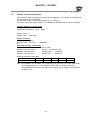
AM-800CL / AB-800CL
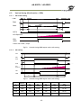
- Contents Before using AM-800CL and AB-800CL ....................................................1. General ....................................................................................2.
Camera nomenclature .................................................................3.
Main features ............................................................................4.
Locations and functions ...............................................................4.1
4.2
4.3
6
7
8
8
9
-
Locations and functions (C-mount) ...............................................................- 9 Locations and functions (F-mount) ............................................................. - 10 Rear panel .......................................................................................... - 11 -
5. Input and output ......................................................................... - 12 5.1 Connectors and pin assignment ................................................................. 5.1.1 Hirose 12Pin connector ...................................................................... 5.1.1.1 Figure ..................................................................................... 5.1.1.2 Pin assignment ........................................................................... 5.1.2 Camera Link connector ...................................................................... 5.1.2.1 Figure ..................................................................................... 5.1.2.2 Pin assignment ........................................................................... 5.1.3 DIP switch SW500 ............................................................................. 5.2 Camera Link interface ............................................................................ 5.3 Interface circuits .................................................................................. 5.3.1 Iris video output .............................................................................. 5.3.2 Trigger input................................................................................... 5.3.3 XEEN output ................................................................................... 5.4 Output ............................................................................................... 5.4.1 Digital output ................................................................................. 5.4.1.1 Bit allocation............................................................................. 5.4.1.2 Camera link output ..................................................................... 5.4.2 Partial scan readout (AOI) (Commands: STL, ETL) .................................... 5.4.2.1
Frame rate calculation if AOI is set ................................................. 5.4.2.2 If the bit allocation is set to 8,10 or 12bit and the binning is OFF or 2x1 ..... 5.4.2.3 If the bit allocation is set to 8,10 or 12bit and the binning is 1x2 or 2x2 ...... 5.4.2.4 If the bit allocation is set to RGB ..................................................... 5.4.2.5 Setting example 1 ....................................................................... 5.4.2.6 Setting example 2 ....................................................................... 5.4.2.7 Setting example 3 ....................................................................... 5.4.3 Binning (Command : BNC) (Only for AM-800CL) ......................................... 5.4.4 Bayer output pattern ........................................................................ -
6.
12
12
12
12
12
12
13
13
14
14
14
15
15
16
16
16
16
17
17
18
18
19
19
20
20
21
21
-
Sensor layout and timing ............................................................ - 22 -
6.1 Sensor layout ....................................................................................... 6.2. Vertical timing (8bit, 10 bit or 12bit for Bit allocation) .................................... 6.2.1 If the binning control is BNC=0(OFF) or BNC=2(2x1) .................................... 6.2.1.1 AOI default setting ( Offset=0, Height=2472) ....................................... 6.2.1.2 AOI setting................................................................................ 6.2.2 If the binning control is BNC=1(1x2) or BNC=3(2x2) .................................... 6.2.2.1 AOI initial setting (Offset=0, Height=2472) ......................................... 6.2.2.2 AOI setting................................................................................ 6.3. Vertical timing (Bit allocation = RGB) ......................................................... 6.3.1 AOI initial setting ............................................................................. 6.3.2 AOI setting ..................................................................................... 6.4. Horizontal timing ................................................................................. 6.4.1 If the binning control is 0=OFF or 2=2x1 .................................................. -
-3-
22
22
22
22
23
23
23
24
25
25
25
26
26
-
AM-800CL / AB-800CL
6.4.2
6.4.3
6.4.4
7.
If the binning control is 1=1x2 or 3=2x2 .................................................. - 26 DVAL output if the Binning control is set to 2=2x1or 3=2x2 ........................... - 26 LVAL-LOW level period ..................................................................... - 27 -
Operating modes ...................................................................... - 28 -
7.1. Acquisition control (Change the frame rate) ................................................
7.2. Exposure setting ..................................................................................
7.2.1 Mode ...........................................................................................
7.2.2 Exposure time setting (Command: PE) ...................................................
7.2.3 Exposure sequence (Commands EXSQ,PES(N), PER(N), EXSR, EXSEP, PE1 ~PE16)
7.3. Trigger Control ....................................................................................
7.3.1 Selection of the trigger input(Command: TI) ............................................
7.3.2
Trigger activation(Command: TA) ........................................................
7.3.3 Trigger Overlap (Command: TO) ...........................................................
7.3.4 Trigger Dump (Command: TD) ..............................................................
7.4. Auto shutter control (Commands: ASC,ASCS,ASCEA,ASCEI)................................
7.5. Normal continuous operation...................................................................
7.6. Timed mode (so-called EPS operation) .......................................................
7.6.1 If the overlap setting is “OFF” .............................................................
7.6.2 If the overlap setting is “Readout” ........................................................
7.7. Trigger width mode (so-called PWC) ..........................................................
7.7.1 If the overlap setting is “Non Overlap” ...................................................
7.7.2 If the overlap setting is “Readout” ........................................................
7.8. Edge-dump mode (so-called RCT) .............................................................
7.9. PIV(Particle Image Velocimetry) ...............................................................
7.10. Operation and function matrix ...............................................................
8.
28
28
29
29
29
29
29
29
30
30
30
31
32
32
33
34
34
35
36
37
37
-
Other functions ....................................................................... - 38 -
8.1
8.2
8.3
8.4.
8.5.
8.6.
8.7.
8.8.
8.9.
8.10.
8.11.
8.12.
9.
-
Black level control (Command : BL) ..........................................................
Gain control (Relative commands GA,GJUT1,2,3) ...........................................
Tap control (Relative commands AWA,ABA,GJUT1, GJUT2,GJUT3)........................
Exposure auto (Related Commands : ASC=1(ON),ASCS,ASCEA,ASCEI) ....................
Auto white balance (Related commands:AWB, PGS, PGR, PGGR, PGGB, PGB) .........
Blemish compensation ...........................................................................
LUT (Relative commands LUTC,LUTR,LUYG, LUTB) .........................................
Gamma (Command: GAMS) .....................................................................
Flat Field Correction (FFC) (Command: SDR) ................................................
Bayer color interpolation (Command : BCIC) (Only for AB-800CL) ......................
Test pattern (Command: TPN) ................................................................
Temperature sensor (Command : TMPO) ....................................................
-
38
38
38
39
39
40
40
41
41
42
42
43
-
Configuring the camera.............................................................. - 44 -
9.1
9.2
9.3.
9.4
10.
RS-232C control ....................................................................................
Communication setting. ..........................................................................
Save and load functions .........................................................................
Command list ......................................................................................
12.1
44
44
45
45
-
Camera control tool ................................................................ - 53 -
10.1. Control tool windows ...........................................................................
10.2. Camera Control Tool interface ................................................................
10.2.1 About Window ...............................................................................
10.2.2 Communication Window ...................................................................
10.2.3 Camera Control Window ...................................................................
11.
12.
-
53
53
53
54
56
-
External appearance and dimensions .......................................... - 58 Specifications ........................................................................ - 60 Spectral response ................................................................................ - 60 -
-4-
AM-800CL / AB-800CL
12.2
Specifications table .............................................................................. - 61 -
Appendix ...................................................................................... - 63 1.
2.
3.
4.
5.
6.
Precautions ............................................................................................ Typical Sensor Characteristics ...................................................................... Caution when mounting a lens on the camera................................................... Caution when mounting the camera .............................................................. Exportation ............................................................................................ References ............................................................................................. -
63
63
63
64
64
64
-
Manual change history ..................................................................... - 65 User's Record ................................................................................ - 66 -
-5-
AM-800CL / AB-800CL
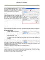
Before using AM-800CL and AB-800CL
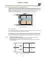
The CCD sensor used in the AM-800CL and AB-800CL operates with four (4) taps and a 40MHz pixel
clock. However, the video output through the Camera Link® interface is 2 taps for monochrome and
Bayer color modes, and 1 tap for RGB color output.
Accordingly, the pixel clock at the Camera Link interface is 80MHz and users should make sure that
the specifications and performance of connected frame grabber boards and PCs can support this
clock speed. The maximum length of the Camera Link cable may also be impacted.
The AM-800CL and AB-800CL are high resolution and high frame rate cameras with 3296(h) x 2472(v)
pixel resolution and a 17fps frame rate for monochrome and Bayer color.
Accordingly, the amount of data produced is very large. If the output is set at 10-bits or 12-bits per
pixel, the total data stream is approx. 2.2 Gbit/sec. as a 16-bit process in the frame grabber board.
A frame grabber board connected to the PCI-32bit bus has a bandwidth of 2.1 Gbits/sec and
therefore, all frames may not be displayed.
In this case, it is recommended to use the PCI-64bit bus or to use a frame grabber board that can
utilize the PCI Express Bus x 8.
JAI recommends using a PC with CPU better than i7.
It should be noted, even though you use the mentioned PC, you might not capture a full of 17fps
image while you view full resolution images on the screen.
-6-
AM-800CL / AB-800CL
1.
General
The AM-800CL is a 4/3 inch monochrome progressive scan CCD camera and the AB-800CL is the
equivalent Bayer mosaic progressive scan CCD camera. Both have 8 million pixels resolution and 4
taps in the sensor. They provide 17 frames per second for continuous scanning with 3296 x 2472 full
pixel resolution.
Both AM-800Cl and AB-800CL are suitable for automated optical inspection applications, such as
solid state device inspection or material surface inspection.
They incorporates various processing circuits such as LUT, FFC(Flat Field Compensation), blemish
compensation and Bayer interpolation. The AM-800CL and AB-800CL work in continuous, single
frame, and multi-frame modes for acquisition control together with timed, trigger width and trigger
controlled exposure controls. Both cameras also have edge-dump and PIV modes.
The AM-800CL has H and V binning modes and both the AM-800CL and AB-800CL have an AOI (Area Of
Interest) mode for achieving a faster frame rate.
The digital output is through a Camera Link® digital interface with 8-bits , 10-bits or 12-bits of
pixel bit depth.
The latest version of this manual can be downloaded from: www.jai.com
The latest version of Camera Control Tool for the AM-800CL and AB-800CL can be downloaded from:
www.jai.com
For camera revision history, please contact your local JAI distributor.
Special note:
In this manual, some new terminologies are used as compared to the terms used in previous JAI
operation manuals.
Previous
EPS
PWC
RCT(Reset Continuous)
Partial scan
Shutter
Auto shutter
New
Timed
Trigger width
Edge-dump
AOI (Area Of Interest)
Exposure
Exposure Auto
-7-
AM-800CL / AB-800CL
2.
Camera nomenclature
The standard camera composition consists of the camera main body and lens protection cap.
The camera is available in the following versions:
AM-800CL-C
AM-800CL-F
Where A stands for "Advanced" family, M stands for "Monochrome", 800 represents the resolution "8
million pixel" , CL stands for "Camera Link" interface and C for C-mount lens or F for F-mount lens
AB-800CL-C
AB-800CL-F
Where A stands for "Advanced" family, B stands for "Bayer mosaic color", 800 represents the
resolution "8 million pixel" , CL stands for "Camera Link" interface and C for C-mount lens or F for
F-mount lens
3.
Main features
C3 Advanced series 4/3 ” progressive scan camera
Monochrome and Bayer mosaic color versions
3296 (h) x 2472 (v) active pixels
5μm square pixels
57dB or more S/N
8-bit, 10-bit or 12-bit output for monochrome and Bayer or 8-bit output RGB color
17 frames/second with full resolution in continuous operation for monochrome or Bayer
output
8.5 frames/second for AB-800CL RGB output (in-camera interpolation)
Various readout modes, horizontal and vertical binning (AM-800CL only) and AOI (Area Of
Interest) modes for faster frame rate
-3dB to +24dB gain control for AM-800CL and 0dB to +24dB for AB-800CL
10μs (1/100,000) to 2 seconds exposure control in 1μs step ( Exposure/Timed control mode)
Timed ,trigger width for exposure control,
Trigger-dump (RCT) and PIV modes for specific applications
Auto gain control
Various pre-processing circuits are provided
Programmable LUT
Gamma correction from 0.45 to 1.0
Flat Field Correction
Bayer white balance with manual or one-push auto (AB-800CL only)
Bayer color interpolation (AB-800CL only)
Blemish compensation
Test pattern signal generator is built in
Auto iris lens video output with H-sync
Choice of lens mounts offered: C-mount or F-mount
Setup by Windows XP/Vista/7 via serial communication
-8-
AM-800CL / AB-800CL
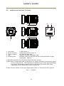
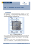
4.
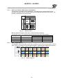
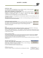
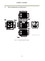
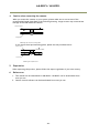
Locations and functions
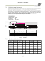
4.1
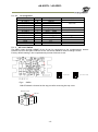
Locations and functions (C-mount)
③
④
⑤
POW ER/ TRIG
D C IN / TRIG
D IGITAL I / O
⑤
①
Lens mount
26-pin connector
12-pin connector
LED
Mounting holes
②
C-mount (Note *1)
Camera Link Interface ( Note *2)
DC+12V and trigger input
Indication for power and trigger input
M3 depth 4.5mm for fixing the camera to the mount plate or tripod
mount plate (Note *3)
*1) Note: Rear protrusion on C-mount lens must be less than 10.0mm.
*2) Note: When a Camera Link cable is connected to the camera, please do not excessively tighten
screws by using a driver. The Camera Link receptacle on the camera might be damaged.
For security, the strength to tighten screws is less than 0.291 Newton meter (Nm).
Tightening by hand is sufficient in order to achieve this.
*3) Note: The part number for the tripod adapter plate (with 1/4"-20 thread) is MP-41 (option).
Fig. 1
Locations
-9-
AM-800CL / AB-800CL
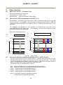
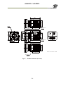
4.2
Locations and functions (F-mount)
④
⑤
③
POWER/ TRIG
DCIN/ TRIG
DIGITAL I / O
⑤
②
①
Lens mount
26-pin connector
12-pin connector
LED
Mounting holes
F-mount (Note *1)
Camera Link Interface ( Note *2)
DC+12V and trigger input
Indication for power and trigger input
M3 depth 4.5mm for fixing the camera to the mount plate or tripod
mount plate (Note *3)
*1) Note: Rear protrusion on F-mount lens must be less than 12.0mm.
*2) Note: When a Camera Link cable is connected to the camera, please do not excessively tighten
screws by using a driver. The Camera Link receptacle on the camera might be damaged.
For security, the strength to tighten screws is less than 0.291 Newton meter (Nm).
Tightening by hand is sufficient in order to achieve this.
*3) Note: The part number for the tripod adapter plate (with 1/4"-20 thread) is MP-41 (option).
Fig. 2
Locations
- 10 -
AM-800CL / AB-800CL
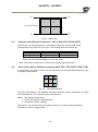
4.3
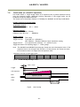
Rear panel
The rear panel mounted LED provides the following information:
Amber:
Power connected - initiating
Steady green: Camera is operating in Continuous mode
Flashing green: The camera is receiving external triggering
POW ER/ TRIG
DC IN / TRIG
Note: The interval of flashing does not correspond with external
trigger duration.
D IGITAL I / O
Fig. 3
- 11 -
Rear panel
AM-800CL / AB-800CL
5. Input and output
5.1
Connectors and pin assignment
5.1.1
Hirose 12Pin connector
5.1.1.1
Figure
Type: HR10A-10R-12PB-01 (Hirose) male.
Use the part number HR10A-10P-12S for the cable side
Fig.4
5.1.1.2
Hirose 12-pin connector
Pin assignment
Pin no.
1
2
3
4
5
6
7
8
9
10
11
12
Signal
GND
DC input
GND
Iris video
GND
Remarks
+12V to +24V
Only for Continuous and Trigger-dump modes.
NC
NC
GND
XEEN out
Trigger in
DC input
GND
*1)
TI=1 (or Camera Link TI=0). *2)
+12V to +24V
*1) XEEN output can be configured with complementary emitter follower circuit or open
collector by internal switch setting. The default is the complementary emitter
follower circuit. See chapter 5.1.3 for the details.
*2) Factory default is trigger via Camera Link
5.1.2 Camera Link connector
5.1.2.1
Figure
Type: 26-pin MDR connector (3M 10226-1A10PL)
Fig.5
Camera Link connector
- 12 -
AM-800CL / AB-800CL
5.1.2.2
Pin assignment
Pin No
1,14
2(-),15(+)
3(-),16(+)
4(-),17(+)
5(-),18(+)
6(-),19(+)
7(+),20(-)
8(-),21(+)
9(-),22(+)
10(+),23(-)
11,24
12,25
13,26
In/Out
O
O
O
O
O
I
O
I
Name
Shield
TxOUT0
TxOUT1
TxOUT2
TxClk
TxOUT3
SerTC (RxD)
SerTFG (TxD)
CC1 (Trigger)
N.C
N.C
N.C
Shield
Note
GND
Data out
Clock for CL
Data out
LVDS Serial Control
Trigger IN
GND
5.1.3 DIP switch SW500
The XEEN output through HIROSE 12-pin #9 can be connected to the complementary emitter
follower circuit or the open collector circuit. DIP switch SW500 is used to change circuits.
Factory default setting is the complementary emitter follower circuit.
1
4
1
4
3
6
Open collector output
Push pull output
6
3
Not used
Fig.6
Not used
SW500
PK9137A board is located at the top part after removing the top cover.
Remove cover
PK9137A
- 13 -
AM-800CL / AB-800CL
5.2
Camera Link interface
Port/Signal
Port A0
Port A1
Port A2
Port A3
Port A4
Port A5
Port A6
Port A7
Port B0
Port B1
Port B2
Port B3
Port B4
Port B5
Port B6
Port B7
Port C0
Port C1
Port C2
Port C3
Port C4
Port C5
Port C6
Port C7
LVAL
FVAL
DVAL
EEN
5.3
8bit
TAP A0
TAP A1
TAP A2
TAP A3
TAP A4
TAP A5
TAP A6
TAP A7
TAP B0
TAP B1
TAP B2
TAP B3
TAP B4
TAP B5
TAP B6
TAP B7
2-tap
10bit
TAP A0
TAP A1
TAP A2
TAP A3
TAP A4
TAP A5
TAP A6
TAP A7
TAP A8
TAP A9
TAP B8
TAP B9
TAP B0
TAP B1
TAP B2
TAP B3
TAP B4
TAP B5
TAP B6
TAP B7
12bit
1-tap
RGB 8-bit
TAP A0
TAP A1
TAP A2
TAP A3
TAP A4
TAP A5
TAP A6
TAP A7
TAP A8
TAP A9
TAP A10
TAP A11
TAP B8
TAP B9
TAP B10
TAP B11
TAP B0
TAP B1
TAP B2
TAP B3
TAP B4
TAP B5
TAP B6
TAP B7
R0
R1
R2
R3
R4
R5
R6
R7
G0
G1
G2
G3
G4
G5
G6
G7
B0
B1
B2
B3
B4
B5
B6
B7
Pin No.
Tx0
Tx1
Tx2
Tx3
Tx4
Tx6
Tx27
Tx5
Tx7
Tx8
Tx9
Tx12
Tx13
Tx14
Tx10
Tx11
Tx15
Tx18
Tx19
Tx20
Tx21
Tx22
Tx16
Tx17
Tx24
Tx25
Tx26
Tx23
Interface circuits
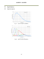
5.3.1
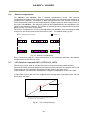
Iris video output
This signal can be used for lens iris control in Continuous and
trigger-dump modes.
The signal for iris video output is taken from the video signal after
the gain control. The signal is 1.0 V p-p (with H-sync) from 75
without termination.
+5V
0.1μ
2K2
1K
IRIS Video Out
1μ
DAC
Fig. 7. Iris video
The iris video signal is composed to average the video level in the center area of each frame and can
be output as a composite signal with H-sync. As shown in the following figure, each frame has its
own video level which is averaged.
- 14 -
AM-800CL / AB-800CL
Fig. 8
Iris video output signal
5.3.2 Trigger input
An external trigger input can be applied to pin#10 of
the 12-pin Hirose connector (when the command TI=1
has been set). The input is AC coupled. To allow long
pulses the input circuit is designed as a flip-flop
circuit. The leading and trailing edges of the trigger
pulse activate the circuit.
The trigger polarity can be changed by TA(Trigger
Activation).
Trigger input level is 4 V 2 V.
Trigger can also be applied through the Camera Link
connector, when the command TI=0 has been sent.
+5V
●
●
15K
Trigger
IN
●
●
●
3K
1K
0.1μ
●
100K
●
22K
1K
+5V
●
Trigger INI B
○
Trigger INI A
0.1μ
1000
●
Fig.9
5.3.3 XEEN output
XEEN is on pin#9 of the 12-pin Hirose connector.
The output uses either a complementary
emitter follower circuit or open-collector.
The output of the complementary emitter
EEN
follower circuit is 3 V (no termination).
When the open collector output is used, the
maximum current is 120mA. However, if the
current is more than 50mA, use thicker cable
for connecting pins #8 and #9. If a thinner
cable is used, it might cause a malfunction
due to the resistance of the cable.
The output can be selected by switch SW500
located inside the camera (trigger IF board).
Trigger input circuit
+5V
10
150
●
10K
●
220
●
●
120
●
TTL
10
0.1μ
SW500
●
○
●
+5V
10K
●
180
100
●
●
●
0.1μ
Open
Collector
1K
1K
●
●
●
EEN is also found in Camera Link.
Fig.10
- 15 -
XEEN output from Hirse-12pin
XEEN
AM-800CL / AB-800CL
5.4
Output
5.4.1 Digital output
5.4.1.1
Bit allocation
CCD out
Black
300mV
334mV
↑
0%
100%
Analog Out
(Equivalent)
Setup 3.6%, 25mV
700mV
8bit
8LSB
222LSB
255LSB
800mV
1023
Digital Out
10bit
32LSB
890LSB
12bit
128LSB
3560LSB
1023LSB
4095LSB
White Clip Level
890
Digital Out [LSB]
100% Level
32
0
5.4.1.2
Black Level
25
Analog Out [mV]
700 800
Fig.11 Bit allocation
Camera link output
The AM-800CL and AB-800CL have a 4-tap readout from the CCD. The 4-tap output is
combined horizontally to output 2 taps through the Camera Link interface.
(TAP C + TAP D)
C
D
A
B
To Camera Link I/F
(TAP A + TAP B)
Fig.12 2-tap output
In the case of RGB interpolation, it is provided as 1-tap output.
C
D
A
B
To Camera Link I/F
Fig.13
RGB 1-tap output
- 16 -
AM-800CL / AB-800CL
5.4.2
Partial scan readout (AOI) (Commands: STL, ETL)
The AOI works like partial scanning. By using the AOI function, a faster frame rate can be
achieved. The start line of the image (Offset Y) and the image height (Height) can be set as
desired. However, the start pixel and/or end pixel of each line cannot be changed. In the
AM-800CL and AB-800CL RGB output, The Offset Y and Height can be set in 1 line
increments. For the AB-800CL Bayer mode, output can be set in 2-line steps.
OFFSET Y
TapB
(TAP C + TAP D)
C
D
Height
A
B
TapA
(TAP A + TAP B)
Fig.14
AOI setting
Note for AOI setting
In the AM-800CL and AB-800CL, the frame rate setting has priority. If AOI is used, the frame
rate setting should use fewer lines that that of AOI height.
For AOI setting, if the upper TAP and lower TAP have the same duration, the fastest frame
rate can be achieved. Thus, if the AOI is centered vertically within the image, the frame
rate is maximized. Examples of the settings are shown in sections 5.4.2.4 and 5.4.2.5.
5.4.2.1
Frame rate calculation if AOI is set
The calculation method for the frame rate in AOI mode depends on the setting
conditions of offset, height, Bit Allocation and binning control.
It also depends on the position of the readout such as the upper TAP, lower TAP and
covering both TAPs.
Lower part (Lower)
C
D
A
B
Lower part part (Upper)
Center part
Upper part (Lower)
Upper part (Upper)
Fig.15
the position of the readout
- 17 -
AM-800CL / AB-800CL
5.4.2.2
If the bit allocation is set to 8,10 or 12bit and the binning control is OFF or 2x1
1) For a centered readout which covers both the upper and lower TAPS
Use the following two formulas to calculate frame lines (A) and frame lines (B).
Use the larger number of frame lines for calculating the frame rate.
If they are the same number of lines, either one can be used.
Frame lines (A) = Roundup (Offset/4) +(1236 –Offset) +26
Frame lines (B) = Roundup{[2473-(Offset+Height)]/4} + [(Offset + Height)-1236] +26
Frame rate(Hz) = 1/ (frame lines number x 0.00004655)
2) If the readout is only in the upper TAP
In this case, Offset < 1236 and (Offset + Height) ≤ 1236
Roundup{(Offset + 1 )/4} + {1236 –Roundup (Offset + height)/4} + Height +26
= Frame lines number
Frame rate (Hz)= 1/(Frame number x 0.00004655)
3) If the readout is only in the lower TAP
In this case, Offset > 1236
{2473 – Roundup[(Offset + Height)/4]} + Roundup(Offset -1236) + Height + 26 =
Frame lines number
Frame rate(Hz) = 1/(Frame lines number x 0.00004655)
5.4.2.3
If the bit allocation is set to 8,10 or 12bit and the binning control is 1x2 or 2x2
Note: In this case, offset and height should use only even numbers.
1) For a centered readout which covers both the upper and lower TAPS
Use the following two formulas to calculate frame lines (A) and frame lines (B).
Use the larger number of frame lines for calculating the frame rate.
If they are the same number of lines, either one can be used.
Frame lines (A) = Roundup (Offset/4) +(1236 –Offset) +20
Frame lines (B) = Roundup{[2473-(Offset+Height)]/4} + [(Offset + Height)-1236] +20
Frame rate(Hz) = 1/ (frame lines number x 0.0000500655)
2) If the readout is only in the upper TAP
In this case, Offset < 1236 and (Offset + Height) ≤ 1236
Roundup{(Offset + 1 )/4} + {1236 –Roundup (Offset + height)/4} + Height/2 +20
= Frame lines number
Frame rate (Hz)= 1/(Frame number x 0.000050055)
3) If the readout is only in the lower TAP
In this case, Offset > 1236
{2473 – Roundup[(Offset + Height)/4]} + Roundup(Offset -1236) + Height/2 + 20 =
Frame lines number
Frame rate(Hz) = 1/(Frame lines number x 0.000050055)
- 18 -
AM-800CL / AB-800CL
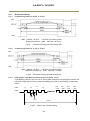
5.4.2.4
If the bit allocation is set to RGB
In this case, the binning control is not available. So there is only one calculation
method.
Roundup{(Offset + 1 )/4} + Roundup{(2472 – Height+Offset)/4}+ Height + 46 =
Frame number
Frame rate(Hz) = 1/(Frame lines number x 0.00004655)
5.4.2.5
Setting example 1
Bit allocation is 8-,10- or 12-bit and the binning control is OFF or 2x1
AOI
Position
Full pixels
Upper TAP
1/2
Center
Lower TAP
Upper TAP, upper
Upper TAP, lower
1/4
Center
Lower TAP, upper
Lower TAP, lower
Upper TAP, upper
Upper TAP, lower
1/8
Center
Lower TAP, upper
Lower TAP, lower
Upper TAP, upper
Upper TAP, lower
1/16
Center
Lower TAP, upper
Lower TAP, lower
Offset
Height
Frame line
Frame Frequency (Hz)
0
2472
1263
17.01
0
618
1236
1236
1236
1236
1263
799
1262
17.01
26.89
17.02
0
616
926
1236
1852
618
618
618
618
618
800
800
568
799
799
26.85
26.85
37.82
26.89
26.89
0
924
1080
1236
2160
310
310
310
310
310
569
569
452
568
568
37.75
37.75
47.53
37.82
37.82
0
1080
1158
1236
2316
154
154
154
154
154
452
452
394
451
451
47.53
47.53
54.52
47.63
47.63
- 19 -
AM-800CL / AB-800CL
5.4.2.6
Setting example 2
Bit allocation is 8-,10- or 12-bit and the binning control is 1x2 or 2x2)
AOI
Position
Offset
Binning V x2
Upper TAP
1/2
Center
Lower TAP
Upper TAP, upper
Upper TAP, lower
1/4
Center
Lower TAP, upper
Lower TAP, lower
Upper TAP, upper
Upper TAP, lower
1/8
Center
Lower TAP, upper
Lower TAP, lower
Upper TAP, upper
Upper TAP, lower
1/16
Center
Lower TAP, upper
Lower TAP, lower
5.4.2.7
Height
Frame line
0
2472
639
30.96
0
618
1236
1236
1236
1236
639
484
638
30.96
40.87
31.01
0
616
926
1236
1852
618
618
618
618
618
485
485
407
484
484
40.79
40.79
48.61
40.87
40.87
0
924
1080
1236
2160
310
310
310
310
310
408
408
368
407
407
48.49
48.49
53.76
48.61
48.61
0
1080
1158
1236
2316
154
154
154
154
154
369
369
349
368
368
53.61
53.61
56.68
53.76
53.76
Setting example 3
Bit allocation is RGB
Partial
Offset
Height
Frame Frequency (Hz)
FrameLine
Frame Freqency
Full
0
2472
2519
8.53
1/2
Any value
1236
1592
13.49
1/4
Any value
618
1129
19.03
1/8
Any value
310
898
23.92
1/16
Any value
154
781
27.51
- 20 -
AM-800CL / AB-800CL
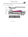
5.4.3
Binning (Command : BNC) (Only for AM-800CL)
This function is available only for AM-800CL. In binning mode, adjacent pixels in the
horizontal direction and/or vertical direction are combined and output as one pixel. The
possible combinations are shown below.
Horizontal
2 pixels
2 Pixels
Vertical
1 Pixel
1 pixel
Fig. 16
Binning modes
Binning achieves a higher frame rate, as well as better sensitivity.
On the other hand, the resolution becomes less than the full frame readout.
Spatial resolution
H x V (Pixels)
Sensitivity
H direction
V direction
1x2
2 times
Unchanged
1/2
2x1
2 times
1/2
Unchanged
2x2
4 times
1/2
1/2
5.4.4
Bayer output pattern
The AB-800CL starts with GRG on odd lines and BGB on even lines as shown below. If AOI is
used, Offset Y can be set every 2 lines and therefore, it always starts with a GRG sequence.
signal out
H1
H2
H3
H4
H5
H6
H7
V1
Gr
R
Gr
R
Gr
R
Gr
V2
B
Gb
B
Gb
B
Gb
B
V3
Gr
R
Gr
R
Gr
R
Gr
Fig. 17
Bayer sequence
- 21 -
AM-800CL / AB-800CL
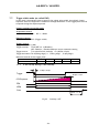
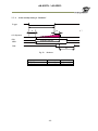
6.
Sensor layout and timing
6.1
Sensor layout
Fig.18
6.2.
Sensor layout
Vertical timing (8bit, 10 bit or 12bit for Bit allocation)
6.2.1
If the binning control is BNC=0(OFF) or BNC=2(2x1)
6.2.1.1
AOI default setting ( Offset=0, Height=2472)
LVAL
FVAL
DVAL
3L
24L
1236L
DATA
Valid Data
CCD Exposure
EEN
XEEN
Frame rate:1263L, 17.009fps
Fig.19
Vertical timing (AOI default)
- 22 -
AM-800CL / AB-800CL
6.2.1.2
AOI setting
LVAL
FVAL
DVAL
3L
Valid data
DATA
CCD
Expsoure
EEN
XEEN
A
B
Fig.20
C
Vertical timing for partial scanning (AOI)
Frame rate examples when the start line and the end line are set as follows
A
B
C
Total line
Frame rate
Offset
HEGHT
(L)
(L)
(L)
(L)
(Hz)
618
1236
181
618
0
799
26.89
927
618
258
309
0
567
37.89
309
618
104
618
78
800
26.85
463
309
142
309
116
567
37.89
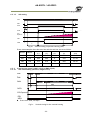
6.2.2
If the binning control is BNC=1(1x2) or BNC=3(2x2)
6.2.2.1
AOI initial setting (Offset=0, Height=2472)
LVAL
FVAL
DVAL
3L
18L
618L
DATA
Valid Data
CCD Exposure
EEN
XEEN
Frame rate: 639L, 30.96fps
Fig.21
Vertical timing for the vertical binning
- 23 -
AM-800CL / AB-800CL
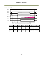
6.2.2.2
AOI setting
LVAL
FVAL
DVAL
3L
Valid data
DATA
CCD
Expsoure
EEN
XEEN
A
Fig.22
B
C
Vertical timing (Vertical binning, AOI setting)
HEGHT
A
(L)
B
(L)
C
(L)
Total line
(L)
Frame rate
(Hz)
618
1236
175
309
0
484
40.87
926
618
98
309
0
407
48.61
308
618
98
309
78
485
41.19
462
310
136
155
116
407
49.08
Offset
- 24 -
AM-800CL / AB-800CL
6.3.
Vertical timing (Bit allocation = RGB)
6.3.1
AOI initial setting
LVAL
FVAL
2472L
DVAL
3L
24L
25L
Valid Data
DATA
CCD Exposure
EEN
XEEN
Frame rate: 2524L, 8.5fps
Fig.23
6.3.2
Vertical timing (RGB output mode, AOI setting)
AOI setting
LVAL
FVAL
DVAL
3L
Valid data
DATA
CCD
Expsoure
EEN
XEEN
A
Fig.24
B
C
Vertical timing (RGB output mode, AOI setting)
Offse
t
HEGHT
A
(L)
B
(L)
C
(L)
Total line
(L)
Frame rate
(Hz)
412
1648
130
1648
123
1901
11.30
618
1236
181
1236
175
1592
13.49
928
618
259
618
252
1129
19.03
1082
310
297
310
290
897
23.95
- 25 -
AM-800CL / AB-800CL
6.4.
Horizontal timing
6.4.1
If the binning control is 0=OFF or 2=2x1
1LVAL 3724clk = 46.55μs
(Exposure start line
Fig.25
6.4.2
1clk=25ns (via Camera Link)
1LVAL 3964 clk = 49.55μs)
Horizontal timing (Vertical binning OFF)
If the binning control is 1=1x2 or 3=2x2
1LVAL 4044clk = 50.55μs 1clk=25ns (via Camera Link)
(Exposure starting line 1LVAL 4364 clk = 54.55μs)
Fig.26
6.4.3
Horizontal timing (Vertical binning ON)
DVAL output if the Binning control is set to 2=2x1or 3=2x2
If the Binning control is set to 2=2x1 or 3=2x2, DVAL is output in one pixel period within the
effective output period. Data is output by adding two pixels in horizontally as described
below.
DATA
1+2
5+6
3+4
7+8
3289
3291
3293
3295
+ 3290
+3292
+3294
+3296
DVAL
12.5ns
12.5ns
3296 clk
Fig.27
DVAL in the vertical binning
- 26 -
AM-800CL / AB-800CL
6.4.4
LVAL-LOW level period
1. When waiting for a trigger signal or at the exposure start line, LVAL-LOW period
varies as shown in the following table.
Binning Control
OFF, 2x1
1x2, 2x2
LVAL-LOW period
Exposure
Ordinary
start
380clk
620clk
700clk
1020clk
LVAL cycle
Ordinary
3724clk 46.55μs
4044clk 50.55μs
Exposure start
3964clk 49.55μs
4364clk 54.55μs
EEN
LVAL
In the right after the exposure start line:
LVAL-LOW period varies “380clk ⇒ 620clk”
700clk
Fig.28 LVAL-LOW period varies
1020clk
2. When the trigger control mode is set to ON and Overlap is set to Readout,
LVAL-LOW period is 1LVAL as the maximum.
Trigger
EEN
LVAL
Maximum 56μs
Fig.29
LVAL-LOW period if Overlap is set to Readout
- 27 -
⇒
AM-800CL / AB-800CL
7.
Operating modes
The following controls are related to capturing the image.
7.1.
Acquisition control (Change the frame rate)
With Exposure Mode set to OFF, the frame rate can be set longer than 1 frame (the normal
period needed to capture all pixels). By doing this, the sensitivity of the image can be
increased. Maximum recommended exposure time is 2 seconds. This function is available
when the trigger mode is OFF.
The setting range is:
Shortest
Longest
~
17.026Hz (1 frame period)
0.5Hz
~
(58.7326658ms)
(2.0 seconds)
7.2.
Exposure setting
- 28 -
AM-800CL / AB-800CL
7.2.1
Mode
The AM-800CL and AB-800CLhave the following exposure modes.
1. EM=0
OFF
2. EM=1
Timed
3. EM=2
Trigger width
7.2.2
Exposure time setting (Command: PE)
PE command can be set if EM (Exposure mode) is set at 1 or 2.
Minimum
time
exposure
~
Maximum
time
exposure
Full pixels
Binning
(HxV)
1x2
10μs
2 sec(Note)
~
2x1
2x2
Note: The AM-800CL and AB-800CL are designed so that frame rate has priority over
exposure time. Accordingly, if the exposure time is set at a longer accumulation time than
1 frame (58.7326ms), the frame rate should be set at a longer time than the exposure time.
7.2.3
Exposure sequence (Commands EXSQ,PES(N), PER(N), EXSR, EXSEP, PE1 ~PE16)
Up to 16 exposure settings can be preset as a sequence. Each setting can also be repeated.
This function is effective only when the trigger mode is ON, the exposure mode is set to
Timed and the exposure sequence is ON.
7.3.
Trigger Control
7.3.1
Selection of the trigger input(Command: TI)
The command “TI” can select the trigger input. At TI=0, the input through Camera Link
(line 0) is active and at TI=1, the input through the Hirose 12-pin connector is active. The
factory default setting is the Camera Link input.
7.3.2
Trigger activation(Command: TA)
The command “TA” can select how to activate the trigger.
TA=0 Rising edge
At the rising edge of the pulse, the accumulation and the
readout will start.
TA=1 Falling edge
At the falling edge of the pulse, the accumulation and the
readout will start.
TA=2 High
During the high level of trigger, the accumulation is activated
and at the low level, the read out is activated.
TA=3 Low
During the low level of trigger, the accumulation is activated
and at the hight level, the read out is activated.
- 29 -
AM-800CL / AB-800CL
7.3.3
Trigger Overlap (Command: TO)
This function sets if a trigger pulse can be accepted while data is being read out or not.
TO=0 OFF
: The trigger pulse is not accepted during CCD readout.
This works the same as the LVAL asynchronous mode.
TO=1 Read Out : The trigger pulse can be accepted during CCD readout.
If the trigger pulse is input during CCD readout, it operates as LVAL
synchronous and if the trigger is input while the CCD is not being
read out, it operates as LVAL asynchronous.
7.3.4
Trigger Dump (Command: TD)
The trigger edge dump has TD=0(disable) and TD=1(enable) modes.
This command can be used with EM=1 (Timed) and it operates the same as RCT mode.
If this mode is “enabled”:
Until the trigger is input, the camera operates continuously and the video signal for the
auto-iris lens is output. When the trigger is input, the fast dump is activated to read out
the electronic charge very quickly, after which the accumulation and the readout are
performed. When the signal is read out, FVAL , LVAL and DVAL are output too.
7.4.
Auto shutter control (Commands: ASC,ASCS,ASCEA,ASCEI)
This turns the auto exposure function “ON” or “OFF” and provides settings for various
parameters.
ASC=0 (OFF), ASC=1 (ON)
ASCS: ASC tracking speed setting. Range is from 1 to 16 (Default is 8).
ASCEA: Maximum exposure time in the ASC mode. Range is from 10 to 1048575 (μs).
ASCEI: Minimum exposure time in the ASC mode. Range is from 10 to 1048575 (μs).
This function is available on the continuous operation and trigger-dump ON.
- 30 -
AM-800CL / AB-800CL
7.5.
Normal continuous operation
This is used for applications which do not require triggering. In this mode, the video signal
for the auto-iris lens is available.
For the video timing, refer to the chapters 6.2 ,6.3 and 6.4.
The frame rate of full pixels readout is 17.0263fps for AM-800CL and 8.5fps for AB-800CL.
Primary settings to use this mode
Acquisition Frame Rate: AR=1~42964
Trigger control
Trigger mode: TM=0 (OFF)
Exposure settings
Exposure mode: EM=1
Exposure time: PE= 10μs ~ 2000000μs
or
Select Auto shutter control(ASC)
Exposure time auto:
ASC=1 (ON)
Exposure time auto speed :
ASCS= 1~16 (Deafult is 8)
Exposure time auto max:
ASCEA= 10μs ~ 1048575μs
Exposure time auto min:
ASCEI= 10μs ~ 1048575μs
Minimum interval of the image
Readout mode
FULL
Minimum frame line
2072
2/3 AOI
1561
1/2 AOI
1303
1/4 AOI
916
1/8 AOI
724
Note: The AM-800CL and AB-800CL are designed to give priority to the frame rate rather
than the exposure time. If the exposure time is set at a longer time than
58.732658ms(1frame time), the frame rate must be set at a longer time than the
exposure time.
- 31 -
AM-800CL / AB-800CL
7.6.
Timed mode (so-called EPS operation)
This mode allows a single image frame to be captured with a preset exposure time by
using the external trigger. Additional settings determine if the trigger pulse can be
accepted during the exposure period.
The frame rate of full pixels readout is 17.0263fps for AM-800CL and 8.5fps for AB-800CL.
Primary settings to use this mode
Acquisition control
Acquisition frame rate: AR= 1~42964
Exposure control
Exposure mode: EM=1 (Timed)
Exposure time: PE=10μs ~ 2000000μs
Trigger control
Trigger mode:
Trigger overlap:
TM=1 (ON)
TO=0 (OFF) or 1=(Readout)
OFF: LVALsync Readout: LVALsync/async automatic setting
Trigger source:
TI=0 (Camera Link, default) or 1 (Hirose 12-pin)
Trigger Activation: TA=0 (Rising edge), 1=(Falling edge)
Note:The AM-800CL and AB-800CL prioritize the frame rate over the exposure time. If the
exposure time is set at longer than 58.73ms (1 frame period), the frame rate must
be increased so that it is longer than the exposure time.
Minimum interval of the trigger pulse
Readout mode
FULL
2/3 AOI
Minimum frame lines
2077
1566
7.6.1
1/2 AOI
1308
1/4 AOI
921
1/8 AOI
729
If the overlap setting is “OFF”
6.56μs ± 0.5μs
Trigger
2l(Min.)
CCD exposure
EEN
Expsoure period
XEEN
FVAL
4.5L ~ 5.5L
Fig.30
Non Overlap
- 32 -
AM-800CL / AB-800CL
7.6.2
If the overlap setting is “Readout”
Trigger
2L(Min.)
LVAL
t
CCD Exposure
EEN
Exposure period
XEEN
FVAL
4.5L ~ 5.5L
Binning Control
OFF, 2x1
1x2, 2x2
Fig.31
t
53μs ± 0.5μs
61μs ± 0.5μs
Readout
- 33 -
AM-800CL / AB-800CL
7.7.
Trigger width mode (so-called PWC)
In this mode, the exposure time is equal to the trigger pulse width. Accordingly, longer
exposure times are supported. Additional settings determine if the trigger pulse can be
accepted during the exposure period.
Primary settings to use this mode
Acquisition control
Acquisition frame rate: AR= 1~42964
Exposure control
Exposure mode: EM=2 (Trigger width)
Trigger control
Trigger mode: TM=1 (ON)
Trigger overlap: TO=0 (OFF) or 1=(Readout)
OFF: LVALsync、Readout:LVALsync/async automatic setting
Trigger source:
TI=0 (Camera Link, default) or 1(Hirose 12-pin)
Trigger Activation: TA=0 (Rising edge), 1=(Falling edge), 2=(Any edge)
Minimum interval of the trigger pulse
Readout mode
FULL
2/3 AOI
Minimum frame lines
2077
1566
7.7.1
1/2 AOI
1308
1/4 AOI
921
1/8 AOI
729
If the overlap setting is “Non Overlap”
6.56µs ± 0.5µs
Trigger
2L(Min.)
36.8μs ± 0.5µs
CCD Exposure
EEN
XEEN
FVAL
4.5L ~ 5.5L
Fig.32
Overlap = OFF
- 34 -
AM-800CL / AB-800CL
7.7.2
If the overlap setting is “Readout”
Trigger
2L(Min.)
t2
t1
CCD Exposure
EEN
Exposure period
XEEN
FVAL
4L
Fig.33
Binning Control
OFF, 2x1
1x2, 2x2
Readout
t1
53μs ± 0.5μs
61μs ± 0.5μs
- 35 -
t2
83.2μs ± 0.5μs
87.2μs ± 0.5μs
AM-800CL / AB-800CL
7.8.
Edge-dump mode (so-called RCT)
Until the trigger is input, the camera operates continuously and the video signal for the
auto-iris lens is output. At this moment, the video signal, FVAL and LVAL are output but
DVAL is not output. When the trigger is input, the fast dump is activated to read out
the electronic charge very quickly, after which the accumulation and the readout are
performed. This fast dump period is 17.19ms. When the accumulated signal against the
trigger is read out, FVAL , LVAL and DVAL are output too.
The frame rate for full pixels readout is;
AM-800CL is “17.0263fps + Fast dump period + Exposure time”
AB-800CL is “8.5fps + Fast dump period + Exposure time”
Primary settings to use this mode
Acquisition control
Acquisition frame rate: AR= 1~42964
Exposure mode: EM=1 (Timed)
Auto mode: ASC=1 (Continuous)
Trigger dump: TD=1(Dump ON)
Note:The AM-800CL and AB-800CL gives priority to the frame rate over the exposure
time. If the exposure time is set at longer than 58.73ms (1 frame period), the frame
rate must be increased so that it is longer than the exposure time.
Minimum interval of the trigger pulse
Readout mode
FULL
2/3 AOI
Minimum frame line
2772
2261
1/2 AOI
2003
1/4 AOI
1616
Trigger
CCD Exposure
17.19ms
EEN
XEEN
FVAL
DVAL
4.5L ~ 5.5L
Fig.34
Trigger dump mode timing
- 36 -
1/8 AOI
1424
AM-800CL / AB-800CL
7.9.
PIV(Particle Image Velocimetry)
The Particle Image Velocimetry mode can be used in applications where 2 images should be
taken with a very short time interval. It can only be used with strobe flash as
illumination. The first accumulation time is 10sec to 58.73ms. Then, the second exposure
will be taken. The accumulation is LVAL asynchronization. The first strobe is activated in
the first exposure duration and the scond strobe is taken during the first frame being
readout. In this way, two strobe lights take two video outputs.
The frame rate for full pixels readout is 8.5fps for both AM-800CL and AB-800CL.
Primary Settings
Exposure mode : Timed
PIV control :
ON
Trigger mode:
TM=1 (ON)
External Trigger
Exposure
EEN
FVAL
DVAL
td
te1
time name
td
te1
te2
itf
tframe1
tframe2
te2 tframe1
ift
tframe2
description
Exposure beginning delay
First exposure time period
Second exposure time
Inter framing time
First Frame read out
Second Frame read out
Fig.35
7.10.
4LVAL
time
5us
10us ~ 58.73ms
58.73ms max
7.9us
58.73ms max
58.73ms max
PIV mode
Operation and function matrix
Operation
mode
Exposure
control
Expsoure
auto
Binning
Continuous
○
○
○
○
○
---
Timed (EPS)
○
×
○
○
×
○
---
×
○
○
×
○
○
○
○
○
○
OFF
JAI_PIV
○
×
○
○
×
OFF
Exposure
Sequence
○
×
○
○
×
OFF
Trigger
width(PWC)
Trigger Dump
(RCT)
- 37 -
AOI
Auto Iris
Overlap
output
Note
AM-800CL / AB-800CL
8.
Other functions
8.1
Black level control
(Command : BL)
This function adjusts the setup level.
Command value : -1024 to 1023
Variable range : -256 to 255 LSB (at 10-bit output)
8.2
Gain control (Relative commands GA,GJUT1,2,3)
The AM-800CL can adjust the gain level from -3dB to +24dB using 0dB as the reference
(Factory default). In the AB-800CL, the master gain can be adjusted from 0dB to +24dB and
R and B gains can be adjusted in the range of -7dB to + 10dB using the master gain as the
reference.
The AM-800CL and AB-800CL has the resolution of x0.00012/step using both analog
gain(0.00359db/step) and digital gain. In the AB-800CL, blue and red channels can adjust
in x0.00012/step by using digital gain.
Refer to the following drawing.
Gain
Setting
Value
Gain
Gain Control Range(AM-800CL)
Gain
Setting
Value
Gain
Master
Master
34dB
672
24dB
672
17dB
Gain Control Range for AB-800CL
Red
Blue
Gain
Setting
Value
R&B
34dB
+17713
24dB
0
17dB
-4533
10dB
+17713
10dB
0
0dB
0
0dB
-3dB
-84
-3dB
-7dB
0
-4533
-7dB
Fig. 36
8.3
Gain control
Tap control (Relative commands AWA,ABA,GJUT1, GJUT2,GJUT3)
The Tap control function adjusts automatically or manually the OFFSET and the gain
differences between the upper and lower taps, and the right and left taps. The sensor
used in the AM-800CLand AB-800CL divides the effective image area into 4(four) areas as
shown in the figure 30 in order to achieve its fast frame rate.
The reference tap for all adjustments is Tap ”A”.
AWA: Adjust the differences of the gain among taps automatically
ABA: Adjust the differences of the OFFSET among taps automatically
GJUT1: Adjust the gain of the TAP1R(B) manually
GJUT2: Adjust the gain of the TAP2L(C) manually
GJUT3: Adjust the gain of the TAP2R(D) manually
Note: 1) The OFFSET cannot be adjusted individually.
2) TAP A cannot be adjusted individually.
- 38 -
AM-800CL / AB-800CL
tapD
TapC
C
D
A
B
To Camera Link I/F
Tap B
Tap A
Fig.37 Tap control
8.4.
Exposure auto (Related Commands : ASC=1(ON),ASCS,ASCEA,ASCEI)
The exposure can be automatically controlled by setting the command ASC to ON.
The adjusting range is 58.733 ms to 10μs. The tracking speed can also be set.
Command
Value
Adjusting range
ASCEA, ASCEI
10μs to 58.733ms
Tracking speed
ASCS
1 to 16 (Default:8)
ASCEA: Sets the maximum exposure in the ASC mode
ASCEI: Sets the minimum exposure in the ASC mode
Note: This function works only in continuous mode or edge-dump mode.
8.5.
Auto white balance (Related commands:AWB, PGS, PGR, PGGR, PGGB, PGB)
In this function, the gain of each R, Gr, Gb and B color can be individually adjusted to get
the proper white balance.
Fig. 38
B1
Gb1
B2
Gr1
R
Gr2
B3
Gb2
B4
Auto white balance
To adjust white balance, the AB-800CL has three methods: manual adjustment, one-push
auto white balance, and continuous auto white balance.
AWB: 0 OFF (Manual adjustment)
1 Once (One-push auto white balance)
2 Continuous (always tracking)
This function can be used with full resolution read out, as well as with AOI readout.
This does not work in trigger mode.
- 39 -
AM-800CL / AB-800CL
8.6.
Blemish compensation
The AM-800CL and AB-800CL have a blemish compensation circuit. This function
compensates blemishes on the CCD sensor (typically pixels with extremely high response or
extremely low response). This applies to both monochrome and color versions. Pixels that
fulfill the blemish criteria can be compensated by adjacent pixels on both columns and, in
the case of the AB-800CL, the defective pixels can be compensated by the same Bayer color
pixels in both adjacent columns. The number of pixels that can be compensated is up to 64
pixels per tap, for a total of 256 pixels.
The built-in compensation circuit for the AM-800CL and AB-800CL uses compensation data
collected in the factory and can be turned ON or OFF. The default setting is OFF.
Defective Pixel
Blemish Compensation Principle
B/W
Color
Fig. 39 Blemish compensation
Note: If defective pixels are found consecutively in the horizontal direction, the blemish
compensation circuit does not work.
8.7.
LUT (Relative commands LUTC,LUTR,LUYG, LUTB)
This function can be used to convert the input to the desired output characteristics.
The Look Up Table (LUT) has 256 points for setup and each point has an 8-bit gain value. The
output level can be created by multiplying the gain data by the input level.
In the AB-800CL, the same LUT characteristic is applied independent of the color value.
If input data is not in the LUT, the weighted mean average data from upper point and the
lower point are used.
CCD output
256
1
The required characteristics can be achieved by multiplying
LUT parameter and each of 256 points.
Fig.40
LUT concept drawing
- 40 -
AM-800CL / AB-800CL
8.8.
Gamma (Command: GAMS)
This command is used for the fine tuning of the set gamma characteristics if the gamma is
set to 0.45 or 0.6. The parameter of GAMS is 0 to 31 and the default is 16.
If GAMS is 16 (default), the normal 0.45 or 0.6 gamma curve is unaffected. By changing the
value of GAMS, the 0.45 or 0.6 gamma curve can be modified.
Fig. 41
8.9.
Gamma compensation
Flat Field Correction (FFC) (Command: SDR)
This function compensates for shading caused by the lens or the light source used. The
method to compensate the shading is to measure the highest luminance level in the image
and use that data as the reference. Luminance levels of other areas are then adjusted so
that the level of the entire area is equal. The block for compensation is 64 pixels x 64
pixels and the complementary process is applied to produce the compensation data with
less error.
Adjustable range
Less 30%
Fig. 42 FFC compensation concept drawing
Note: Under the following conditions, the FFC circuit may not work properly.
If there is some area in the image with a video level less than 70%
If part of the image or the entire image is saturated
If the highest video level in the image is less than 300LSB (at 10-bit output)
SDM: 0=OFF, 1=Factory (Use factory data), 2=User (User setting data)
To generate user data for setting FFC:
Execute the command RS (FFC re-calibration) and store the result in the user area.
- 41 -
AM-800CL / AB-800CL
8.10.
Bayer color interpolation (Command : BCIC) (Only for AB-800CL)
This function is available only for AB-800CL. The AB-800CL uses a CCD with an RGB Bayer
pattern. If the Bayer color interpolation is not used, the following RAW data can be
output.
B
Gb
B
Gb
B
Gb
B
Gb
B
Gb
Gr
R
Gr
R
Gr
R
Gr
R
Gr
R
B
Gb
B
Gb
B
Gb
B
Gb
B
Gb
Gr
R
Gr
R
Gr
R
Gr
R
Gr
R
Fig.43
Bayer pattern
The RAW data contains only luminance information for each color and outputs as a
monochrome signal. The Bayer color interpolation can complement lacking color
information on each pixel and output RGB color data as the result. Color interpolation
compensates for the lack of color information by using information from adjacent pixels.
The following is the concept drawing for the color interpolation process.
B1
Gb1
B2
Gb1
B1
Gb2
Gr1
R
Gr2
R1
Gr
R2
Gb3
B2
Gb4
B3
Gb2
B4
Gr
R1
Gr1
R2
Gb1
B
Gb2
R3
Gr2
R4
Fig.44 Color interpolation concept drawing
8.11.
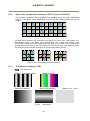
Test pattern (Command: TPN)
TPN=0:Test pattern off
TPN=1:AM-800:Black-Wihte
TPN=2 Gray Pattern1
AB-800: Color bar
TPN=3: Gray Pattern2
Fig.45
Test pattern
- 42 -
TPN=4: white(100%)
AM-800CL / AB-800CL
8.12.
Temperature sensor (Command : TMPO)
This function reads out the temperature inside the camera.
The measuring range : -55 to +125ºC
Resolution
: 0.0625 ºC
The following table shows examples of values which can be read out by the TMPO
command.
The display resolution in the JAI camera control tool is 1 ºC.
- 43 -
AM-800CL / AB-800CL
9.
Configuring the camera
9.1
RS-232C control
All configuration of the AM-800CL and AB-800CL cameras are done via Camera Link. The
camera can be set up from a PC running terminal emulator software, or using JAI´s camera
control software.
Below is the description of the ASCII based short command protocol.
9.2
Communication setting.
Baud Rate
Data Length
Start Bit
Stop Bit
Parity
Xon/Xoff Control
9600 bps
8 bit
1 bit
1 bit
None
None
RS 232C cable
TXD
CAMERA RXD
GND
1 CD
4 DTR
6 DSR
2 RXD
3 TXD
5 GND
7 RTS
8 CTS
9 CI
Protocol.
Transmit setting to camera:
NN=Parameter<CR><LF> (NN is any kind of command. Capital or small letters.)
The camera answers:
COMPLETE<CR><LF>
Note: Some commands can only be requested.
To have all communication visible on the emulator screen, start with:
EB=1<CR><LF>
The camera answers:
COMPLETE<CR><LF>
Transmit request command to camera:
NN?<CR><LF> (NN is any kind of command.)
The camera answers:
NN=Parameter<CR><LF>
Transmit the following to have the camera‟s actual settings:
ST?<CR><LF>
The camera answers:
A complete list of the current settings
Transmit the following to have a command list:
HP?<CR><LF>
The camera answers:
A list with all commands and possible settings
Invalid parameters sent to camera: (99 is an invalid parameter)
SH=99<CR><LF>
The camera answers:
02 Bad Parameters!!<CR><LF>
To see firmware number.
VN?<CR><LF>
To see camera ID. It shows the manufacturing lot number.
ID?<CR><LF>
- 44 -
9 pin
D-con
PC COM
PORT
AM-800CL / AB-800CL
9.3.
Save and load functions
The following commands are for storing and loading camera settings in the camera EEPROM.
Load settings. LD.
This command will load previously stored settings to the camera. 3 user settings can be stored in
the camera EEPROM. 1 factory setting is also stored in the camera. The settings stored in the last
used user area are used as default settings at power up.
Save Settings. SA.
This command will store the actual camera settings to 1 of the 3 user areas in the camera EEPROM.
EEPROM Area. EA.
If received, the camera will return the last used user area number.
9.4
Command list
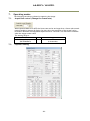
Command
Name
Format
Parameter
Remarks
A - General settings and utility commands.
1
Camera Status
ST?<CR><LF>
Request
Actual setting
2
Online Help
Request
HP?<CR><LF>
Command list
3
Firmware
Version
VN?<CR><LF>
3 digits
(e.g) 100 = Version
1.00
4
Camera ID
Request
ID?<CR><LF>
max 12 characters
5
Model Name
Request
MD?<CR><LF>
max 12 characters
6
User ID
UD=[Param.]<CR><LF>
UD?<CR><LF>
User can save and
load free text.(12 or
less characters)
7
Error code
ERRER=[Param.]<CR><LF
>
ERRER?<CR><LF>
One of following values will be replied
from the camera
0=One-Push has not been finished yet.
1=Succeeded.
2=Error1. Green image was too bright.
3=Error2. Green image was too dark.
4=Error3. Timeout-error occurred.
B – Image format control
1
Height
ETL=[Param.]<CR><LF>
ETL?<CR><LF>
SC=1: :2 to 2472
AB-800:2Line step
AM-800:1Line step
2
Offset Y
STL=[Param.]<CR><LF>
STL?<CR><LF>
SC=1: :1 to 2471
AB-800:2Line step
AM-800:1Line step
0=off
Only AM-800CL
3
Binning Vertical BNC=[Param.]<CR><LF>
- 45 -
AM-800CL / AB-800CL
Command
Name
4
PixelFormat
Format
Parameter
BNC?<CR><LF>
1=1x2,
2=2x1
3=2x2
BA=[Param.]<CR><LF>
BA?<CR><LF>
0=8bit, 1=10bit , 2=12bit,
3=RGB
Remarks
C – Test image selector
1
Test Image
selector
TPN=[Param.]<CR><LF>
TPN?<CR><LF>
0=OFF
1=Color bar (AB-xxx) /
Black-White (AM-xxx)
2= Gray horizontal ramp
3= Gray Vertical ramp
4= White
D – Acquisition control
1
Acquisition
Frame Rate
AR=[Param.]<CR><LF>
AR?<CR><LF>
1 to 42964
E – Trigger control
1
Trigger Mode
TM=[Param.]<CR><LF>
TM?<CR><LF>
0=off
1=on
2
Trigger source
TI=[Param.]<CR><LF>
TI? <CR><LF>
0= Line0(Camera Link)
1= Line1(Hirose 12pin)
3
Trigger
Activation
TA=[Param.]<CR><LF>
TA? <CR><LF>
0= Rising edge
1=Falling edge
2=High
3=Low
4
Trigger overlap
TO=[Param.]<CR><LF>
TO?<CR><LF>
0= off
1= Read out
F – Exposure control
1 Exposure Mode
EM=[Param.]<CR><LF>
EM?<CR><LF>
0=OFF
1=Timed
2=Trigger width
2 Exposure time
PE=[Param.]<CR><LF>
PE?<CR><LF>
10μs ~ 2000000μs
3 ExposureAuto
ASC=[Param.]<CR><LF>
ASC?<CR><LF>
0=off , 1=Continuous
Available when
EM=1,2
4
ExposureAuto
speed
ASCS=[Param.]<CR><LF>
1 to 16
ASCS?<CR><LF>
ASC Tracking speed
setting, Default=8
5
ExposureAuto
Max
ASCEA=[Param.]<CR><LF
>
10 to 1048575 us unit
ASCEA?<CR><LF>
Maximum Exposure
value when ASC is
1
6
ExposureAuto
Min
ASCEI=[Param.]<CR><LF
>
10 to 1048575 us unit
ASCEI?<CR><LF>
Minimum Exposure
value when ASC is
1
- 46 -
AM-800CL / AB-800CL
Command
Name
7
Trigger edge
Dump
Format
Parameter
Remarks
TD=[Param.]<CR><LF>
TD? <CR><LF>
0= Dump off
1=Dump on
GA=[Param.]<CR><LF>
GA?<CR><LF>
-84 to 672 (AM-xxxCL)
0 to 672 (AB-XXXCL)
for AFE 1L, 1R, 2L,
2R
-2393~3379
(Data+8192)/ 8192
±3dB
for AFE 1L, 1R, 2L,
2R
G – Analog control
1 GainAnalog All
2
FineGain Digital FGA=[Param.]<CR><LF>
All
FGA?<CR><LF>
3 Gain Auto
AGC=[Param.]<CR><LF>
AGC?<CR><LF>
0=OFF
1=Continuous
4
Gain Auto
Reference
AGCF=[Param.]<CR><LF>
0 to 8192
AGCF?<CR><LF>
5
Gain Auto
speed
AGCS=[Param.]<CR><LF>
1 to 16
AGCS?<CR><LF>
AGC tracking speed
Setting ,Default=8
Gain Auto
6 Maximum gain
value
AGCGA=[Param.]<CR><L
0 to 672 (AM-xxxCL)
F>
84 to 672 (AB-XXXCL)
AGCGA?<CR><LF>
Gain Auto
7 Minimal gain
value
AGCGI=[Param.]<CR><LF
-84 to 588 (AM-xxxCL)
>
0 to 588 (AB-XXXCL)
AGCGI?<CR><LF>
8 Black Level
BL=[Param.]<CR><LF>
BL?<CR><LF>
-1024 to 1023
Digital User Setup
Master
H – Balance Ratio
1
BalanceRatio
RED
PGR=[Param.]<CR><LF>
PGR?<CR><LF>
-4533~17713
(Data+8192)/ 8192
-7~+10dB
(Only AB-800CL)
Pixel Gain for WB
2
BalanceRatio
Blue
PGB=[Param.]<CR><LF>
PGB?<CR><LF>
-4533~17713
(Data+8192)/ 8192
-7~+10dB
(Only AB-800CL)
Pixel Gain for WB
3
Blance White
auto
AWB=[Param.]<CR><LF>
0=OFF
1=Once (Run)
2=Continuous
Only AB-800CL
0=Complete.
1=Too Bright.
2=Too dark.
3=Timeout Error.
4=Busy.
5=Limit.
6= Trig is not set as
Normal.
Only AB-800CL
Request the
4 Result of Blance AWRS?<CR><LF>
white auto
I – LUT control
1 LUT selector
LUTC=[Param.]<CR><LF> 0=off
- 47 -
AM-800CL / AB-800CL
Command
Name
Format
Parameter
LUTC?<CR><LF>
2
Gamma
Selector
Remarks
1=Gamma
2=LUT
GAMS=[Param.]<CR><LF
>
GAMS?<CR><LF>
0 to 16
( Only Gamma)
LUT data
3 communication
for Red
transfer by a serial method.
LUTR=[Param.]<CR><LF> The number of the data is
LUTR?<CR><LF>
512.
Param=0 to 8191
After sending
consecutive 512
data, LUT data can
be renewed
LUT data
4 communication
for Green
transfer by a serial method.
LUTG=[Param.]<CR><LF> The number of the data is
LUTG?<CR><LF>
512.
Param=0 to 8191
After sending
consecutive 512
data, LUT data can
be renewed
LUT data
5 communication
for Blue
transfer by a serial method.
LUTB=[Param.]<CR><LF> The number of the data is
LUTB?<CR><LF>
512.
Param=0 to 8191
After sending
consecutive 512
data, LUT data can
be renewed
J – Gain and black level for TAP balance
1
Gain auto Tap
Balance
Request the
Result of Gain
2
auto Tap
balance
AWA=[Param.]<CR><LF>
0=OFF
1=Once(Run)
2=Continuous
WBRS?<CR><LF>
0=Complete.
1=Too Bright.
2=Too dark.
3=Timeout Error.
4=Busy.
5=Limit.
6= Trig is not set as
Normal.
-891~1000
(Data+8192)/ 8192
±1dB
3
Fine Gain for
Tap 2
GJUT2=[Param.]<CR><LF
>
GJUT2?<CR><LF>
4
Fine Gain for
Tap 3
GJUT3=[Param.]<CR><LF
>
GJUT3?<CR><LF>
-891~1000
(Data+8192)/ 8192
±1dB
for pixel Gain 2L
5
Fine Gain for
Tap 4
GJUT4=[Param.]<CR><LF
>
GJUT4?<CR><LF>
-891~1000
(Data+8192)/ 8192
±1dB
for pixel Gain 2R
-891~1000
PGR2=[Param.]<CR><LF>
(Data+8192)/ 8192
PGR2?<CR><LF>
±1dB
(Only AB-800CL)
Pixel Gain for Tap2
Pixel Gain Blue PGB2=[Param.]<CR><LF> -891~1000
Tap2
PGB2?<CR><LF>
(Data+8192)/ 8192
(Only AB-800CL)
Pixel Gain for Tap2
PixelGain RED
6
Tap2
7
for pixel Gain 1R
- 48 -
AM-800CL / AB-800CL
Command
Name
Format
Parameter
Remarks
±1dB
-891~1000
Pixel Gain RED PGR3=[Param.]<CR><LF>
8
(Data+8192)/ 8192
Tap3
PGR3?<CR><LF>
±1dB
(Only AB-800CL)
Pixel Gain for Tap3
9
-891~1000
Pixel Gain Blue PGB3=[Param.]<CR><LF>
(Data+8192)/ 8192
Tap3
PGB3?<CR><LF>
±1dB
(Only AB-800CL)
Pixel Gain for Tap3
10
-891~1000
Pixel Gain RED PGR4=[Param.]<CR><LF>
(Data+8192)/ 8192
Tap4
PGR4?<CR><LF>
±1dB
(Only AB-800CL)
Pixel Gain for Tap4
-891~1000
Pixel Gain Blue PGB4=[Param.]<CR><LF>
11
(Data+8192)/ 8192
Tap4
PGB4?<CR><LF>
±1dB
(Only AB-800CL)
Pixel Gain for Tap4
12
Black level auto
ABA=[Param.]<CR><LF>
Tap balance
Request the
Result of Black
13
level auto Tap
balance
0=OFF
1=Once (Run)
2=Continuous
BBRS?<CR><LF>
0=Complete.
1=Too Bright.
2=Too dark.
3=Timeout Error.
4=Busy.
5=Limit.
6= Trig is not set as
Normal.
14
Fine Black for
tap 2
BL2=[Param.]<CR><LF>
BL2?<CR><LF>
-512 to 511
Tap2 Black Fine For
User
15
Fine Black for
tap 3
BL3=[Param.]<CR><LF>
BL3?<CR><LF>
-512 to 511
Tap3 Black Fine For
User
16
Fine Black for
tap 4
BL4=[Param.]<CR><LF>
BL4?<CR><LF>
-512 to 511
Tap4 Black Fine For
User
BayerPixel
17 FineBlack for
tap 1L-R
BLR1=[Param.]<CR><LF>
BLR1?<CR><LF>
BayerPixel
18 FineBlack for
tap 1L-B
BLB1=[Param.]<CR><LF>
BLB1?<CR><LF>
BayerPixel
19 FineBlack for
tap 1R-R
BLR2=[Param.]<CR><LF>
BLR2?<CR><LF>
BayerPixel
20 FineBlack for
tap 1R-B
BLB2=[Param.]<CR><LF>
BLB2?<CR><LF>
21 BayerPixel
BLR3=[Param.]<CR><LF>
-512 to 511
-512 to 511
-512 to 511
-512 to 511
-512 to 511
- 49 -
Tap1 Black Fine For
User
Tap1 Black Fine For
User
Tap2 Black Fine For
User
Tap2 Black Fine For
User
Tap3 Black Fine For
AM-800CL / AB-800CL
Command
Name
FineBlack for
tap 2L-R
Format
Parameter
BLR3?<CR><LF>
User
BayerPixel
22 FineBlack for
tap 2L-B
BLB3=[Param.]<CR><LF>
BLB3?<CR><LF>
BayerPixel
23 FineBlack for
tap 2R-R
BLR4=[Param.]<CR><LF>
BLR4?<CR><LF>
BayerPixel
24 FineBlack for
tap 2R-B
BLB4=[Param.]<CR><LF>
BLB4?<CR><LF>
-512 to 511
Tap3 Black Fine For
User
-512 to 511
Tap4 Black Fine For
User
-512 to 511
Tap4 Black Fine For
User
K - Blemish
1
Blemish
Reduction
BLM=[Param.]<CR><LF>
BLM?<CR><LF>
0=off, 1=Black, 2=White,
3=Both
2
ReCalibrate
Blemish
BMRC=[Param.]<CR><LF>
Param:
1=Black
Blemish
3 Threshold
White
BMTHW=[Param.]<CR><L
F>
BMTHW?<CR><LF>
0 to 16383
4 BLMP White H
BMWH=[Param1],[Param2 Param1:Blemish No. 1 to
]<CR><LF>
256
BMH?[Param1]<CR><LF> Param2:H position
5 BLMP White V
BMWV=[Param1],[Param2 Param1:Blemish No. 1 to
]<CR><LF>
256
BMV?[Param1]<CR><LF> Param2:V position
2=White
L – ALC control
Auto Iris Lens
1 Control Signal
output
AIC=[Param.]<CR><LF>
AIC?<CR><LF>
0=off, 1=on
2
Iris Reverse
Gain
IRRG=[Param.]<CR><LF>
0=ON
1=OFF
3
Iris State
Control
IRSC=[Param.]<CR><LF>
0=Video
2=Open
IRSL=[Param.]<CR><LF>
0 to 255
CHA=[Param.]<CR><LF>
CHA?<CR><LF>
1=Low Right;
2=Low Center;
3=Low Left;
4=Middle Right;
5=Middle Center;
6=Middle Left;
7=High Right;
8=High Center;
9=High Left;
4 Iris Sync Level
5 Channel area
Remarks
- 50 -
1=Close
AM-800CL / AB-800CL
Command
Name
Format
Parameter
Remarks
M – Flat field correction
Flat Field
1 Correction
Control
SDM=[Param.]<CR><LF>
SDM?<CR><LF>
2 Recalibrate FFC RS=[Param1]<CR><LF>
3
Request the
Result of FFC
0=Off, 1=Factory, 2=User
0 Only
SDRS?<CR><LF>
0=Complete.
1=Too Bright.
2=Too dark.
3=Timeout Error.
4=Busy.
5=Limit.
6= Trig is not set as
Normal.
TMP0?<CR><LF>
0 to 0xFFF8 (/ 128 → ℃)
NR=[Param.]<CR><LF>
NR?<CR><LF>
0=off, 1=on
Save User Area
N - Others
1 Temperature
2
Noise Reject
SW
O – Sequence exposure control operation
1 Exposure
Sequence
EXSQ=[Param.]<CR><LF> 0=OFF
EXSQ?<CR><LF>
1=ON
Exposure
2 Sequence No
N (1 ~ 16)
PES(N)=[Param.]<CR><LF
>
0 ~ 15
PES(N)?<CR><LF>
Exposure
3 Repeat Time
N (1 ~ 16)
PER(N)=[Param.]<CR><LF
>
0 ~ 15
PER(N)?<CR><LF>
Available when
EM=1,2
EXSR=[Param.]<CR><LF> 0=OFF
EXSR?<CR><LF>
1=ON
Effective when
EXSQ=1. Only
command 1 is used.
In the firmware, 1 is
immediately turned
to 0.
Exposure
5 Sequence End
Point
EXSEP=[Param.]<CR><LF
0=OFF
>
1=ON
EXSEP?<CR><LF>
Effective when
EXSQ=1. Only
command 1 is used.
In the firmware, 1 is
immediately turned
to 0.
6 Exposure time 1
PE1=[Param.]<CR><LF>
PE1?<CR><LF>
10μs ~ 2000000μs
Available when
EXSQ=1
7
PE2=[Param.]<CR><LF>
PE2?<CR><LF>
10μs ~ 2000000μs
Available when
EXSQ=1
8 Exposure time 3 PE3=[Param.]<CR><LF>
10μs ~ 2000000μs
Available when
Exposure
4 Sequence
Reset
Exposure time 2
- 51 -
AM-800CL / AB-800CL
Command
Name
Format
Parameter
PE3?<CR><LF>
Remarks
EXSQ=1
9 Exposure time 4
PE4=[Param.]<CR><LF>
PE4?<CR><LF>
10μs ~ 2000000μs
Available when
EXSQ=1
10 Exposure time 5
PE5=[Param.]<CR><LF>
PE5?<CR><LF>
10μs ~ 2000000μs
Available when
EXSQ=1
11 Exposure time 6
PE6=[Param.]<CR><LF>
PE6?<CR><LF>
10μs ~ 2000000μs
Available when
EXSQ=1
12 Exposure time 7
PE7=[Param.]<CR><LF>
PE7?<CR><LF>
10μs ~ 2000000μs
Available when
EXSQ=1
13 Exposure time 8
PE8=[Param.]<CR><LF>
PE8?<CR><LF>
10μs ~ 2000000μs
Available when
EXSQ=1
14 Exposure time 9
PE9=[Param.]<CR><LF>
PE9?<CR><LF>
10μs ~ 2000000μs
Available when
EXSQ=1
15
Exposure time PE10=[Param.]<CR><LF>
10
PE10?<CR><LF>
10μs ~ 2000000μs
Available when
EXSQ=1
16
Exposure time PE11=[Param.]<CR><LF>
11
PE11?<CR><LF>
10μs ~ 2000000μs
Available when
EXSQ=1
17
Exposure time PE12=[Param.]<CR><LF>
12
PE12?<CR><LF>
10μs ~ 2000000μs
Available when
EXSQ=1
18
Exposure time PE13=[Param.]<CR><LF>
13
PE13?<CR><LF>
10μs ~ 2000000μs
Available when
EXSQ=1
19
Exposure time PE14=[Param.]<CR><LF>
14
PE14?<CR><LF>
10μs ~ 2000000μs
Available when
EXSQ=1
20
Exposure time PE15=[Param.]<CR><LF>
15
PE14?<CR><LF>
10μs ~ 2000000μs
Available when
EXSQ=1
21
Exposure time PE15=[Param.]<CR><LF>
16
PE14?<CR><LF>
10μs ~ 2000000μs
Available when
EXSQ=1
P - Saving and loading data in EEPROM
1
2
Load Setttings
(from Camera LD=[Param.]<CR><LF>
EEPROM)
0=Factory area
1=User 1 area
2=User 2 area
3=User 3 area
Save Settings
(to Camera
EEPROM)
1=User 1 area
2=User 2 area
3=User 3 area
Note : parameter 0 is not
allowed
SA=[Param.]<CR><LF>
EEPROM
3 Current Area No EA?<CR><LF>
Request.
0=Factory area
1=User 1 area
2=User 2 area
3=User 3 area
- 52 -
Latest used DATA
AREA becomes
default at next
power up.
The camera return
the latest used DATA
AREA.
AM-800CL / AB-800CL
10.
Camera control tool
The AM-800CL and AB-800CL camera Control Tool can be downloaded from JAI Web
site www.jai.com. This control software is available for Windows2000/XP/Vista/7.
In this control tool, the developers guide is included in order for customers to
create their own programs.
10.1.
Control tool windows
Here is some practical information about the Camera Control Tool:
1. The Camera Control Tool bar is always on top of other windows.
2. When you minimize the Camera Control Tool bar all open windows will close.
3. It is possible to work with the Camera Control Tool when the camera is online and
when the camera is offline.
4. The newer JAI cameras always start up with the last used user area (but for some old
models it will start up with the last saved user area.)
5. The Camera Control Tool saves the last used settings (not the user area), which don‟t
have to be the same as for the last saved user area.
6. The setup file ‟CameraName.ini‟ stores all information about camera settings. When
the program is started the last settings for the program are loaded from the
file ‟CameraName.ini‟
10.2.
Camera Control Tool interface
The Camera Control software consists of the main tool bar and
associated tool windows. When each icon in the main tool bar
is clicked, the associated window will open. The program is
refreshed after reboot.
The Camera control tool includes an About Window, Communication Window and Camera Control
Window.
10.2.1
About Window
The About Window contains a picture of the
camera and information about the version of
the program, Internet connection to JAI A/S
and access to the help documents.
The List box that contains the help documents
will list all files, which have the extension .pdf
and that are found in the program (default)
folder
It is possible to download updated operation
manuals from the jai website:
http://www.jai.com
The About Window also shows Model Name,
Camera ID and User ID. It is possible to edit and
save free text in User ID.
At the bottom of the windows (all windows but
the Communication Window is a colored bar. The bar is red when the Camera Control Tool is not
connected to a camera or when the camera is turned off. The bar is green when the Camera Control
- 53 -
AM-800CL / AB-800CL
Tool is connected to a camera and the camera is turned on.
10.2.2
Communication Window
The Communication Window is used to connect
the Camera Control Tool with the JAI camera.
Depending on the camera there are 2 possible
ways to communicate with a JAI camera.
RS-232C
Select the communication port, where the serial
cable is connected from the list box in the
„Communication Port‟ field, or click the „Auto‟
button to search for a camera on communication
port 1 to 16. The camera control program
automatically sends a camera request on every
communication port. The user is prompted to use
a communication port if a camera answers the
request.
RS-232C and Camera Link
The Communication Window looks a bit different when it is possible to communicate with the
camera using Camera Link and RS-232 com port. The Communication area contains 2 list boxes now.
RS-232CCommunication
1. Select ‟COM-ports‟ from the ‟CL
Manufacturer/COM-ports‟ list Box.
2. Select the communication port, where
the serial cable is connected to the
camera from the ‟Serial Port‟ list box or click the „Auto‟ button to search for a camera on
communication port 1 to 16.
The Serial Port list box and the Auto search button are only active when COM-ports is
selected.
Camera Link communication
The ‟CL Manufacturer/COM-ports‟ list box also
contains DLL file names (or frame grabber
names) for all Camera Link frame grabbers that
are installed in the pc. This is done by using a DLL file called "clserial.dll" to upload all frame
grabber DLLs that are found in the pc.
Just select the option for the frame grabber that is installed in the pc.
Auto Search
Click the auto button to search for a camera on communication port 1 to 16. The camera control
program automatically sends a camera request on every communication port. The user is prompted
to use a communication port if a camera answers the request.
This button is only used for RS-232 communication.
- 54 -
AM-800CL / AB-800CL
Off/On-line Mode
The Camera Control Tool Application can run offline (without a camera attached)
and all functions are fully functional in offline mode.
Offline mode is indicated in the Communication Window, where a status field with
graphic and text indicates the on/offline status.
Changing the selected communication port (from the Communication Window)
changes the online/offline status. If a camera is found on the selected
communication port the application runs online otherwise offline.
Changing the settings in the application will automatically update the camera settings when the
application is online.
If the application loses connection with the camera it will automatically go to offline mode and it is
indicated in the Communication Window.
Synchronize program and camera
The Camera Control software has the ability to synchronize either the camera or
the program. Click Synchronize camera to write all settings from the program to
the camera or click the Synchronize program to load all settings from the
camera to the program.
Files
When clicking the Write to File or Read from File button, the user is prompted for a file using a
standard file dialog. New files are created if they do not already exist.
Files for camera settings have the “.cam” extension. Information about the communication port is
not stored in the files. All settings are automatically sent to the camera when a file has been loaded
(if the camera is online).
Factory and User Settings
Use the Store button to store the current camera settings into the user settings area in EEPROM.
Current camera settings are not saved when the camera is turned off. To save current camera
settings you have to save them to the available user areas.
Use the Load button to restore previously saved camera settings from either the Factory or the User
EEPROM area.
Write All Camera Data to File.
Click the “Write Camera Data” button to save all camera settings into a
text file. The information that can be saved is:
Model Name, Camera ID, User ID, Firmware Version, Current Settings,
Factory Settings and the available User Areas.
The file is formatted as shown in the picture below:
EEPROM Current Area.
Click the „Get Area‟ button to read the power up settings area number.
- 55 -
AM-800CL / AB-800CL
10.2.3
Camera Control Window
10.2.3.1 Exposure Control
10.2.3.2
Gain Control
- 56 -
AM-800CL / AB-800CL
10.2.3.3
Blemish Control
When “Open LUT table” is clicked, the left side window will open, for example for blue channel.
- 57 -
AM-800CL / AB-800CL
11.
External appearance and dimensions
40
( 1. 57)
62
( 2. 44)
45
( 1. 77)
45
( 1. 77)
4-M3 Depth 4.5
( depth0. 18)
3
( 0. 12)
POWER/TRIG
40
( 1. 57)
DC IN /TRIG
27. 5
( 1. 08)
36
( 1. 42)
55
( 2. 17)
36
( 1. 42)
21
( 0. 83)
7
14
(0.28) (0.55)
4-M3 Depth 4.5
( depth0. 18)
φ 30
( φ 1. 18)
C Mount
DIGITAL I / O
69
4-M3 Depth 4.5
( depth0. 18)
55
( 2. 17)
40
( 1. 57)
27. 5
( 1. 08)
45
( 1. 77)
4-M3 Depth 4.5
( depth0. 18)
Fig. 46
Outside dimensions (C mount)
- 58 -
Outsi de si ze tol er ance:± 0. 3mm
AM-800CL / AB-800CL
40
(1.57)
62
(2.44)
F Mount
50
(1.97)
36
(1.42)
45
(1.77)
14
(0.55)
45
(1.77)
3
(0.12)
40
(1.57)
φ57
(φ2.24)
φ41
(φ1.61)
POWER/ TRIG
DCIN/ TRIG
27.5
(1.08)
55
(2.17)
4-M3 Depth 4.5
(depth0.18)
DIGITAL I / O
55
(2.17)
16
(0.630)
12
(0.472)
98
(1.77)
40
(1.57)
27.5
(1.08)
4-M3 Depth 4.5
(depth0.18)
45
(1.77)
4-M3 Depth 4.5
(depth0.18)
Fig.47
Outside dimensions (F mount)
- 59 -
Outside size tolerance:±0.3mm
AM-800CL / AB-800CL
12.
Specifications
12.1
Spectral response
Fig. 41
Spectral response (AM-800CL)
Fig.42
Spectral response (AB-800CL)
- 60 -
AM-800CL / AB-800CL
12.2
Specifications table
Specifications
AM-800CL
Scanning system
Synchronizing system
Image sensor
Sensing area
Cell size
Active pixels (for output)
Pixel clock(sensor)
Horizontal (Camera Link)
Vertical
Frame rate
(Full Resolution)
Full resolution
Image Format
Binning (h x v)
AOI
Sensitivity on sensor (minimum)
S/N ratio
Digital
Video output
Camera Link
3296(h) x 2472(v)
1 x 2 3296(h) x 1236(v)
2 x 1 1648(h) x 2472(v)
2 x 2 1648(h) x 1236(v)
Height
1 line / step
Height
2 line / step
Offset Y 1 line / step
Offset Y 2 line / step
Note: number of horizontal pixels cannot be changed.
0.01 Lux (Max. gain, Shutter OFF,
0.2 Lux (Max. gain, Shutter
50% video )
OFF,50% Green, w/IR cut filter)
More than 57 dB (0dB gain, CCD output=300mV)
2 tap
Pixel clock
80 MHz
8-bit, 10-bit, 12-bit
Iris video output
Camera Link : FVAL, LVAL, DVAL, EEN
Hirose 12-pin: XEEN, 4V p-p (No termination)
Acquisition frame rate
Trigger
Control
Gain
White balance
BAYER 8-bit, 10-bit, 12-bit
RGB 8-bit
Analog, 0.7 V p-p with 0.3V H.sync
Sync output
Exposure
Control
(Trigger)
Continuous mode
Bayer output 17.0263fps
(58.7ms)
RGB output 8.5fps (117ms)
Bayer 3296(h) x 2472(v)
RGB 3296(h) x 2472(v)
Continuous mode
17.0263 fps (58.7ms)
Pixel format
Pixel bit depth
AB-800CL
Progressive scan, 4 taps
Internal
4/3 inch Monochrome interline CCD 4/3 inch Bayer color interline CCD
18.13 (h) x 13.60 (v) mm 22.66 mm diagonal
5.5 (h) x 5.5 (v) m
3296 (h) x 2472 (v)
3296 (h) x 2472 (v) (TBD)
40 MHz
21.50537 KHz (1H=46.5µs) (3720 clocks per line) (Pixel clock 80MHz)
Total lines 2520 (Effective 2472)
OFF
Timed
Trigger width
PIV
Trigger- dump
Source
Activation
Frame rate can be varied from 17.026Hz to 0.5Hz
10μs to 58.73ms(Shutter OFF), 1μs step
10μs to 2 sec.
Line 0=Camera Link CC1 or Line1=Hirose 12P 10pin
Rising edge or falling edge
Level High or Level Low
Manual/Auto : -3dB to +24 dB
Manual/Auto : 0dB to +24 dB
(1 Step 0.01 dB)
(1 Step 0.01 dB)
Fine gain (Digital gain)
Fine gain (Digital gain)
(1step=0.00012 times)
(1step=0.00012 times)
OFF: Manual
ON: One push white balance
Range: 3200K to 9000K
- 61 -
AM-800CL / AB-800CL
32 LSB at 10-bit output,
-256 LSB to 255 LSB can be changed, 1 step is 0.25dB
(at 10-bit output)
OFF: γ=1.0, ON= 256 points can be set
0.45 to 1.0 can be set, Adjusting step is 0.05
Black level
LUT
Gamma
Flat Field Compensation
Blemish Compensation (Bright)
Color interpolation
Test pattern
Temperature sensor
Compensated by 128 x 128 pixels block
Built in,
maximum 64 pixels for dark and bright compensation per 1 tap
(note: black compensation is only by factory preset)
3 x 3 interpolation matrix
OFF/Black-white/Gray H-ramp/
OFF/Color bar/Gray H-ramp /
Gray V-ramp/white(100%)
Gray V-ramp /White(100%)
-55 to +125ºC (measuring range), resolution is 0.0625ºC
Serial communication
Camera Link or Hirose 12-pin
Power
DC+12V to +24V ± 10%, 7.8W (at normal operation, DC+12V)
C mount or F mount
The rear protrusion on C mount lens must be less than 10mm.
The rear protrusion on F mount lens must be less than 12mm
Lens mount
Flange back
C mount : 17.526 mm, tolerance 0 to -0.05 mm
F mount :
46.5 mm, tolerance 0 to -0.05 mm
Sensor alignment
Optical filter
Operating temperature
Humidity
Storage temp/humidity
Vibration
Shock
Regulatory
Size
Weight
X and Y axis: ± 0.1 mm ( at center)
- Protection glass only
Optical low pass filter
-5C to +50C
20 – 80% non-condensing
-25C to +60C/20% to 80 % non-condensing
10G (20Hz to 200Hz, XYZ)
70G
CE (EN61000-6-2 and EN61000-6-3), FCC part 15 class B, RoHS, WEEE
C-mount
55 x 55 x 69 mm (W x H x D)
F-mount
55 x 55 x 98 mm (W x H x D)
C-mount
280g
F-mount
340g,
Note1): Approximately 5 minutes pre-heating is required to get the mentioned specifications.
Note2): The above specifications are subject to change without notice.
- 62 -
AM-800CL / AB-800CL
Appendix
1.
Precautions
Personnel not trained in dealing with similar electronic devices should not service this camera.
The camera contains components sensitive to electrostatic discharge. The handling of these
devices should follow the requirements of electrostatic sensitive components.
Do not attempt to disassemble this camera.
Do not expose this camera to rain or moisture.
Do not face this camera towards the sun, extreme bright light or light reflecting objects.
When this camera is not in use, put the supplied lens cap on the lens mount.
Handle this camera with the maximum care.
Operate this camera only from the type of power source indicated on the camera.
Power off the camera during any modification such as changes of jumper and switch setting.
2.
Typical Sensor Characteristics
The following effects may be observed on the video monitor screen. They do not indicate any
fault of the camera, but do associate with typical sensor characteristics.
V. Aliasing
When the CCD camera captures stripes, straight lines or similar sharp patterns, jagged edges
may appear on the monitor.
Blemishes
All cameras are shipped without visible image sensor blemishes.
Over time some pixel defects can occur. This does not have a practical effect on the operation
of the camera. These will show up as white spots (blemishes).
Exposure to cosmic rays can cause blemishes to appear on the image sensor. Please take care to
avoid exposure to cosmic rays during transportation and storage. It is recommended using sea
shipment instead of air flight in order to limit the influence of cosmic rays on the camera. Pixel
defects/blemishes also may emerge due to prolonged operation at elevated ambient
temperature, due to high gain setting, or during long time exposure. It is therefore
recommended to operate the camera within its specifications.
Patterned Noise
When the sensor captures a dark object at high temperature or is used for long time integration,
fixed pattern noise may appear on the video monitor screen.
3.
Caution when mounting a lens on the camera
When mounting a lens on the camera dust particles in the air may settle on the surface of the
lens or the image sensor of the camera. It is therefore important to keep the protective caps on
the lens and on the camera until the lens is mounted. Point the lens mount of the camera
downward to prevent dust particles from landing on the optical surfaces of the camera. This
work should be done in a dust free environment. Do not touch any of the optical surfaces of the
camera or the lens.
- 63 -
AM-800CL / AB-800CL
4.
Caution when mounting the camera
When you mount the camera on your system, please make sure to use screws of the
recommended length described in the following drawing. Longer screws may cause serious
damage to the PCB inside the camera.
Camera chassis
4.5mm
± 0.2mm
5.0mm ± 0.2mm
Fixing plate
Mounting the camera to fixing plate
If you mount the tripod mounting plate, please use the provided screws.
Camera chassis
4.5mm ± 0.2mm
5.0mm ± 0.2mm
Tripod mount
Attaching the tripod mount
5.
Exportation
When exporting this product, please follow the export regulation of your own country.
6.
References
1. This manual can and datasheet for AM-800CL / AB-800CL can be downloaded from
www.jai.com
2. Camera control software can be downloaded from www.jai.com
- 64 -
AM-800CL / AB-800CL
Manual change history
Date
March
2011
Revision
Ver.1.0
Changes
New release
- 65 -
AM-800CL / AB-800CL
User's Record
Camera type:
AM-800CL / AB-800CL
Revision:
……………..
Serial No.
……………..
Firmware version.
……………..
For camera revision history, please contact your local JAI distributor.
User's Mode Settings.
User's Modifications.
Company and product names mentioned in this manual are trademarks or registered trademarks of their respective owners.
JAI A-S cannot be held responsible for any technical or typographical errors and reserves the right to make changes to products and
documentation without prior notification.
Europe, Middle East & Africa
Asia Pacific
Americas
Phone +45 4457 8888
Fax +45 4491 3252
Phone +81 45 440 0154
Fax +81 45 440 0166
Phone (toll-free) +1 800 445 5444
Phone +1 408 383 0300
Visit our web site at www.jai.com
- 66 -