1
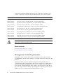
Sun Datacenter InfiniBand
Switch 36
User’s Guide
Part No. 820-7746-13
April 2011, Revision A
Copyright © 2009, 2011 Oracle and/or its affiliates. All rights reserved.
This software and related documentation are provided under a license agreement containing restrictions on use and disclosure and are protected by
intellectual property laws. Except as expressly permitted in your license agreement or allowed by law, you may not use, copy, reproduce, translate,
broadcast, modify, license, transmit, distribute, exhibit, perform, publish, or display any part, in any form, or by any means. Reverse engineering,
disassembly, or decompilation of this software, unless required by law for interoperability, is prohibited.
The information contained herein is subject to change without notice and is not warranted to be error-free. If you find any errors, please report them to us
in writing.
If this is software or related software documentation that is delivered to the U.S. Government or anyone licensing it on behalf of the U.S. Government, the
following notice is applicable:
U.S. GOVERNMENT RIGHTS Programs, software, databases, and related documentation and technical data delivered to U.S. Government customers are
"commercial computer software" or "commercial technical data" pursuant to the applicable Federal Acquisition Regulation and agency-specific
supplemental regulations. As such, the use, duplication, disclosure, modification, and adaptation shall be subject to the restrictions and license terms set
forth in the applicable Government contract, and, to the extent applicable by the terms of the Government contract, the additional rights set forth in FAR
52.227-19, Commercial Computer Software License (December 2007). Oracle America, Inc., 500 Oracle Parkway, Redwood City, CA 94065.
This software or hardware is developed for general use in a variety of information management applications. It is not developed or intended for use in any
inherently dangerous applications, including applications which may create a risk of personal injury. If you use this software or hardware in dangerous
applications, then you shall be responsible to take all appropriate fail-safe, backup, redundancy, and other measures to ensure its safe use. Oracle
Corporation and its affiliates disclaim any liability for any damages caused by use of this software or hardware in dangerous applications.
Oracle and Java are registered trademarks of Oracle and/or its affiliates. Other names may be trademarks of their respective owners.
AMD, Opteron, the AMD logo, and the AMD Opteron logo are trademarks or registered trademarks of Advanced Micro Devices. Intel and Intel Xeon are
trademarks or registered trademarks of Intel Corporation. All SPARC trademarks are used under license and are trademarks or registered trademarks of
SPARC International, Inc. UNIX is a registered trademark licensed through X/Open Company, Ltd.
This software or hardware and documentation may provide access to or information on content, products, and services from third parties. Oracle
Corporation and its affiliates are not responsible for and expressly disclaim all warranties of any kind with respect to third-party content, products, and
services. Oracle Corporation and its affiliates will not be responsible for any loss, costs, or damages incurred due to your access to or use of third-party
content, products, or services.
Copyright © 2009, 2011 Oracle et/ou ses affiliés. Tous droits réservés.
Ce logiciel et la documentation qui l’accompagne sont protégés par les lois sur la propriété intellectuelle. Ils sont concédés sous licence et soumis à des
restrictions d’utilisation et de divulgation. Sauf disposition de votre contrat de licence ou de la loi, vous ne pouvez pas copier, reproduire, traduire,
diffuser, modifier, breveter, transmettre, distribuer, exposer, exécuter, publier ou afficher le logiciel, même partiellement, sous quelque forme et par
quelque procédé que ce soit. Par ailleurs, il est interdit de procéder à toute ingénierie inverse du logiciel, de le désassembler ou de le décompiler, excepté à
des fins d’interopérabilité avec des logiciels tiers ou tel que prescrit par la loi.
Les informations fournies dans ce document sont susceptibles de modification sans préavis. Par ailleurs, Oracle Corporation ne garantit pas qu’elles
soient exemptes d’erreurs et vous invite, le cas échéant, à lui en faire part par écrit.
Si ce logiciel, ou la documentation qui l’accompagne, est concédé sous licence au Gouvernement des Etats-Unis, ou à toute entité qui délivre la licence de
ce logiciel ou l’utilise pour le compte du Gouvernement des Etats-Unis, la notice suivante s’applique :
U.S. GOVERNMENT RIGHTS. Programs, software, databases, and related documentation and technical data delivered to U.S. Government customers
are "commercial computer software" or "commercial technical data" pursuant to the applicable Federal Acquisition Regulation and agency-specific
supplemental regulations. As such, the use, duplication, disclosure, modification, and adaptation shall be subject to the restrictions and license terms set
forth in the applicable Government contract, and, to the extent applicable by the terms of the Government contract, the additional rights set forth in FAR
52.227-19, Commercial Computer Software License (December 2007). Oracle America, Inc., 500 Oracle Parkway, Redwood City, CA 94065.
Ce logiciel ou matériel a été développé pour un usage général dans le cadre d’applications de gestion des informations. Ce logiciel ou matériel n’est pas
conçu ni n’est destiné à être utilisé dans des applications à risque, notamment dans des applications pouvant causer des dommages corporels. Si vous
utilisez ce logiciel ou matériel dans le cadre d’applications dangereuses, il est de votre responsabilité de prendre toutes les mesures de secours, de
sauvegarde, de redondance et autres mesures nécessaires à son utilisation dans des conditions optimales de sécurité. Oracle Corporation et ses affiliés
déclinent toute responsabilité quant aux dommages causés par l’utilisation de ce logiciel ou matériel pour ce type d’applications.
Oracle et Java sont des marques déposées d’Oracle Corporation et/ou de ses affiliés.Tout autre nom mentionné peut correspondre à des marques
appartenant à d’autres propriétaires qu’Oracle.
AMD, Opteron, le logo AMD et le logo AMD Opteron sont des marques ou des marques déposées d’Advanced Micro Devices. Intel et Intel Xeon sont des
marques ou des marques déposées d’Intel Corporation. Toutes les marques SPARC sont utilisées sous licence et sont des marques ou des marques
déposées de SPARC International, Inc. UNIX est une marque déposée concédée sous licence par X/Open Company, Ltd.
Ce logiciel ou matériel et la documentation qui l’accompagne peuvent fournir des informations ou des liens donnant accès à des contenus, des produits et
des services émanant de tiers. Oracle Corporation et ses affiliés déclinent toute responsabilité ou garantie expresse quant aux contenus, produits ou
services émanant de tiers. En aucun cas, Oracle Corporation et ses affiliés ne sauraient être tenus pour responsables des pertes subies, des coûts
occasionnés ou des dommages causés par l’accès à des contenus, produits ou services tiers, ou à leur utilisation.
Contents
Using This Documentation
Installing the Switch
ix
1
Understanding Switch Specifications
Physical Specifications
2
Environmental Requirements
Acoustic Noise Emissions
Electrical Specifications
1
3
3
4
Network Management Connector and Pins
USB Management Connector and Pins
QSFP Connector and Pins
Routing Service Cables
4
5
6
7
Power Cord Requirements
7
Management Cable Requirements
Understanding InfiniBand Cabling
InfiniBand Cable Cautions
InfiniBand Cable Guidelines
InfiniBand Cable Types
8
9
10
11
12
InfiniBand Cable Path Lengths
InfiniBand Cable Bundling
12
13
Floor and Underfloor Delivery of InfiniBand Cables
Overhead Delivery of InfiniBand Cables
14
14
iii
Preparing for Installation
15
Installation Preparation
Suggested Tools
15
16
Antistatic Precautions
16
Installation Responsibilities
Installation Sequence
17
17
▼
Verify Shipping Carton Contents
▼
Route the InfiniBand Cables
▼
Install the Switch in the Rack
Powering On the Switch
18
19
20
25
▼
Attach the Management Cables
▼
Attach the Power Cords
26
28
Accessing the Management Controller
▼
Access the Management Controller From the Network
Management Port 31
▼
Access the Management Controller From the USB Management
Port 32
▼
Verify the Switch Status
▼
Start the Subnet Manager
Connecting InfiniBand Cables
34
36
38
▼
Attach the InfiniBand Cables
▼
Check Link Status
38
44
Verifying the InfiniBand Fabric
44
▼
Discover the InfiniBand Fabric Topology
▼
Perform Diagnostics on the InfiniBand Fabric
▼
Validate the InfiniBand Fabric and Report Errors
Administering the Switch
49
Troubleshooting the Switch
49
Switch Hardware Problems
iv
31
50
Sun Datacenter InfiniBand Switch 36 User’s Guide • April 2011
45
46
47
InfiniBand Fabric Problems
Identifying LEDs
53
56
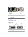
Front Status LEDs
Rear Status LEDs
57
57
▼
Check Chassis Status LEDs
▼
Check Network Management Port Status LEDs
▼
Check Link Status LEDs
▼
Check Power Supply Status LEDs
▼
Check Fan Status LEDs
58
59
59
60
60
Understanding Routing Through the Switch
61
Switch Chip Port to QSFP Connectors and Link LED Routes
QSFP Connectors and Link LEDs to Switch Chip Port Routes
Signal Route Through the Switch
Switch GUIDs Overview
62
63
64
Understanding Administrative Commands
Hardware Command Overview
66
InfiniBand Command Overview
66
ILOM Command Overview
Monitoring the Hardware
62
65
66
67
▼
Display Switch General Health
▼
Display the State of the Chassis Status LEDs
▼
Display Power Supply Status
▼
Check Board-Level Voltages
▼
Display Internal Temperatures
▼
Display Fan Status
▼
Display Switch Environmental and Operational Data
▼
Display Chassis FRU ID
▼
Display Power Supply FRU ID
68
68
69
70
71
71
72
73
73
Contents
v
▼
Display Switch Firmware Versions
▼
Display the Switch Chip Port to QSFP Connector Mapping
▼
Locate a Switch Chip or Connector From the GUID
▼
Display Switch Chip Boot Status
▼
Display Link Status
▼
Display Switch Chip Port Status
▼
Display Switch Chip Port Counters
75
76
76
77
Monitoring the InfiniBand Fabric
78
78
80
▼
Identify All Switches in the Fabric
▼
Identify All HCAs in the Fabric
▼
Display the InfiniBand Fabric Topology (Simple)
▼
Display the InfiniBand Fabric Topology (Detailed)
▼
Display a Route Through the Fabric
▼
Display the Link Status of a Node
▼
Display Counters for a Node
▼
Display Data Counters for a Node
▼
Display Low-Level Detailed Information About a Node
▼
Display Low-Level Detailed Information About a Port
Monitoring the Subnet Manager
80
81
82
82
83
83
85
86
86
87
89
▼
Display Subnet Manager Status
▼
Display Recent Subnet Manager Activity
▼
Display Subnet Manager Priority, Prefix, and Controlled Handover
State 90
▼
Display the Subnet Manager Log
Controlling the Hardware
vi
74
89
91
92
▼
Restart the Management Controller
▼
Restart the Entire Switch
▼
Reset the Switch Chip
▼
Recover Ports After Switch Chip Reset
92
93
94
Sun Datacenter InfiniBand Switch 36 User’s Guide • April 2011
94
90
▼
Disable a Switch Chip Port
▼
Enable a Switch Chip Port
▼
Change the Administrator Password
96
97
Controlling the InfiniBand Fabric
98
98
▼
Perform Comprehensive Diagnostics for the Entire Fabric
▼
Perform Comprehensive Diagnostics for a Route
▼
Determine Changes to the InfiniBand Fabric Topology
▼
Find 1x, SDR, or DDR Links in the Fabric
▼
Determine Which Links Are Experiencing Significant Errors
▼
Clear Error Counters
103
▼
Clear Data Counters
103
▼
Check All Ports
▼
Reset a Port
▼
Set Port Speed
105
▼
Disable a Port
106
▼
Enable a Port
99
100
101
102
103
104
107
Controlling the Subnet Manager
108
▼
Set the Subnet Manager Priority
▼
Set the Subnet Manager Prefix
▼
Enable Subnet Manager Controlled Handover
▼
Enable the Subnet Manager
▼
Disable the Subnet Manager
Servicing the Switch
99
109
110
111
111
112
113
Replaceable Components
113
Servicing Power Supplies
115
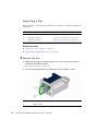
Inspecting a Power Supply
115
▼
Identify the Power Supply
▼
Inspect the Power Supply Hardware
116
117
Contents
vii
▼
Inspect the Power Supply Connectors
▼
Power Off a Power Supply
▼
Remove a Power Supply
▼
Install a Power Supply
▼
Power On a Power Supply
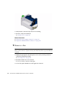
Servicing Fans
118
119
121
126
▼
Identify the Fan
▼
Inspect the Fan Hardware
127
▼
Inspect the Fan Connector
127
▼
Remove a Fan
▼
Install a Fan
126
128
130
Servicing InfiniBand Cables
132
Inspecting the InfiniBand Cables
132
▼
Identify the InfiniBand Cable
▼
Inspect the InfiniBand Cable Hardware
▼
Inspect the InfiniBand Cable Connectors
▼
Remove an InfiniBand Cable
▼
Install an InfiniBand Cable
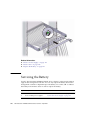
Servicing the Battery
133
134
137
139
▼
Remove the Switch From the Rack
▼
Replace the Battery
Firmware Upgrades
viii
123
125
Inspecting a Fan
Index
117
141
146
147
Sun Datacenter InfiniBand Switch 36 User’s Guide • April 2011
140
133
134
Using This Documentation
This user’s guide provides detailed procedures that describe preparation,
installation, administration, and service for the Sun Datacenter InfiniBand Switch 36
from Oracle. This document is written for technicians, system administrators,
authorized service providers, and users who have advanced experience installing,
administering, and servicing InfiniBand fabric hardware.
■
“Related Documentation” on page ix
■
“Documentation, Support, and Training” on page x
Related Documentation
The documents listed as online are available at:
(http://www.oracle.com/pls/topic/lookup?ctx=E19197-01&id=
homepage)
Application
Title
Format
Location
Getting started
Sun Datacenter InfiniBand Switch 36 Getting
Started Guide
Printed
PDF
Shipping
kit
Online
Last-minute
information
Sun Datacenter InfiniBand Switch 36 Product
Notes
PDF
Online
Installation,
administration,
and service
Sun Datacenter InfiniBand Switch 36 User’s
Guide
PDF
HTML
Online
ix
Application
Title
Format
Location
Command
reference
Sun Datacenter InfiniBand Switch 36 Command
Reference
PDF
HTML
Online
Compliance
Sun Datacenter InfiniBand Switch 36 Safety and
Compliance Guide
PDF
Online
Oracle ILOM
information
Oracle Integrated Lights Out Manager (ILOM)
3.0 Supplement for the Sun Datacenter InfiniBand
Switch 36
PDF
HTML
Online
The Oracle ILOM 3.0 documents listed as online are available at:
(http://www.oracle.com/pls/topic/lookup?ctx=E19860-01&id=
homepage)
Application
Title
Format
Location
Last-minute
information
Oracle Integrated Lights Out Manager (ILOM) 3.0
Feature Updates and Release Notes
PDF
HTML
Online
Getting started
Oracle Integrated Lights Out Manager (ILOM) 3.0
Getting Started Guide
PDF
HTML
Online
Overview
Oracle Integrated Lights Out Manager (ILOM) 3.0
Concepts Guide
PDF
HTML
Online
Administration
from web
interface
Oracle Integrated Lights Out Manager (ILOM) 3.0
Web Procedures Guide
PDF
HTML
Online
Administration
from CLI
interface
Oracle Integrated Lights Out Manager (ILOM) 3.0
CLI Procedures Guide
PDF
HTML
Online
Administration
from SNMP and
IPMI interface
Oracle Integrated Lights Out Manager (ILOM) 3.0
Management Protocols Reference Guide
PDF
HTML
Online
Documentation, Support, and Training
These web sites provide additional resources:
x
■
Documentation (http://www.oracle.com/technetwork/documentation/in
dex.html)
■
Support (https://support.oracle.com)
Sun Datacenter InfiniBand Switch 36 User’s Guide • April 2011
■
Training (https://education.oracle.com)
Using This Documentation
xi
xii
Sun Datacenter InfiniBand Switch 36 User’s Guide • April 2011
Installing the Switch
The following topics describe the installation of the switch. The topics are listed in
the order of completion.
■
“Understanding Switch Specifications” on page 1
■
“Routing Service Cables” on page 7
■
“Understanding InfiniBand Cabling” on page 9
■
“Preparing for Installation” on page 15
■
“Verify Shipping Carton Contents” on page 18
■
“Install the Switch in the Rack” on page 20
■
“Powering On the Switch” on page 25
■
“Connecting InfiniBand Cables” on page 38
■
“Verifying the InfiniBand Fabric” on page 44
Related Information
■
“Administering the Switch” on page 49
■
“Servicing the Switch” on page 113
■
Switch Remote Administration
■
Switch Reference
Understanding Switch Specifications
These topics describe the specifications of the switch, the connectors found on the
switch chassis, and the pinouts of those connectors.
■
“Physical Specifications” on page 2
■
“Environmental Requirements” on page 3
■
“Acoustic Noise Emissions” on page 3
■
“Electrical Specifications” on page 4
1
■
“Network Management Connector and Pins” on page 4
■
“USB Management Connector and Pins” on page 5
■
“QSFP Connector and Pins” on page 6
Related Information
■
“Install the Switch in the Rack” on page 20
■
“Powering On the Switch” on page 25
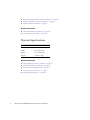
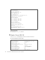
Physical Specifications
Dimension
Measurements
Width
17.52 in. (445.0 mm)
Depth
24 in. (609.6 mm)
Height
1.75 in. (44.5 mm)
Weight
23.0 lbs (11.4 kg)
Related Information
2
■
“Verify Shipping Carton Contents” on page 18
■
“Install the Switch in the Rack” on page 20
■
“Environmental Requirements” on page 3
■
“Acoustic Noise Emissions” on page 3
■
“Electrical Specifications” on page 4
Sun Datacenter InfiniBand Switch 36 User’s Guide • April 2011
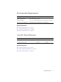
Environmental Requirements
Parameter
Operating
Ambient temperature
41˚F to 89.6˚F (5˚C to 32˚C)
Relative humidity
5% to 85% noncondensing, 80˚F (27˚C) maximum wet bulb
Elevation (Sun requirement)
Maximum 9840 feet (3000 meters) at 104˚F (40˚C)
Related Information
■
“Physical Specifications” on page 2
■
“Acoustic Noise Emissions” on page 3
■
“Electrical Specifications” on page 4
Acoustic Noise Emissions
Parameter
Operating
Idling
Acoustic power LWAd (1B=10dB)
7.1 B
7.2 B
Acoustic pressure LpAm
58.9 dBA
59.0 dBA
Related Information
■
“Physical Specifications” on page 2
■
“Environmental Requirements” on page 3
■
“Electrical Specifications” on page 4
Installing the Switch
3
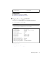
Electrical Specifications
Parameter
AC Version Requirement
Voltage
100 VAC to 240 VAC single phase, 47 to 63 Hz
Current (per input)
5.4 A maximum per input at 100 VAC
Current (total)
5.6 A maximum total for all inputs at 100 VAC
Power
550 Watts (Total input power is approximately equally
divided among the operating power supplies)
Related Information
■
“Power Cord Requirements” on page 7
■
“Attach the Power Cords” on page 28
■
“Physical Specifications” on page 2
■
“Environmental Requirements” on page 3
■
“Acoustic Noise Emissions” on page 3
Network Management Connector and Pins
The following table lists the pinout of the network management connector.
4
Pin
Signal
1
TXD+
2
TXD-
3
RXD+
4
Not used
5
Not used
6
RXD-
Sun Datacenter InfiniBand Switch 36 User’s Guide • April 2011
Pin
Signal
7
Not used
8
Not used
Related Information
■
“Management Cable Requirements” on page 8
■
“Attach the Management Cables” on page 26
■
“Access the Management Controller From the Network Management Port” on
page 31
■
“USB Management Connector and Pins” on page 5
■
“QSFP Connector and Pins” on page 6
USB Management Connector and Pins
The following table lists the pinout of the USB management connector.
Pin
Signal
1
+5 VDC
2
- Data
3
+ Data
4
GND
Related Information
■
“Management Cable Requirements” on page 8
■
“Attach the Management Cables” on page 26
■
“Access the Management Controller From the USB Management Port” on page 32
■
“Network Management Connector and Pins” on page 4
Installing the Switch
5
■
“QSFP Connector and Pins” on page 6
QSFP Connector and Pins
The QSFP connector is a single InfiniBand port connection.
The following table lists the pinout for each connection.
Pin
Signal
Pin
Signal
Pin
Signal
Pin
Signal
1
GND
11
SCL
21
RX2n
31
Reserved
2
TX2n
12
SDA
22
RX2p
32
GND
3
TX2p
13
GND
23
GND
33
TX3p
4
GND
14
RX3p
24
RX4n
34
TX3n
5
TX4n
15
RX3n
25
RX4p
35
GND
6
TX4p
16
GND
26
GND
36
TX1p
7
GND
17
RX1p
27
ModPrsL
37
TX1n
8
ModSelL
18
RX1n
28
IntL
38
GND
9
LPMode_Reset
19
GND
29
VccTx
10
VccRx
20
GND
30
Vcc1
The following table provides descriptions of the QSFP signals.
6
Signal
Description
GND
Ground for both signal and power return
SDA
I2C interface data
Sun Datacenter InfiniBand Switch 36 User’s Guide • April 2011
Signal
Description
SCL
I2C interface clock
ModSelL
Module select on low - Enables reception of I2C commands.
ResetL
Reset on low
LPMode
Low power mode
ModPrsL
Module presence on low - Identifies existence of QSFP connector.
IntL
Interrupt on low - Enables fault indication.
Related Information
■
“InfiniBand Cable Types” on page 12
■
“Connecting InfiniBand Cables” on page 38
■
“Network Management Connector and Pins” on page 4
■
“USB Management Connector and Pins” on page 5
Routing Service Cables
These topics describe cable routing requirements:
■
“Power Cord Requirements” on page 7
■
“Management Cable Requirements” on page 8
Related Information
■
“Understanding InfiniBand Cabling” on page 9
Power Cord Requirements
The power supplies are in a N+N redundancy. Line power is provided from two
sources, A and B.
Installing the Switch
7
Your switch country kit should contain two power cords that are specific to your
country or application. The following table describes the power cords available.
Cable Part Number
Description
X311L (180-1097)
North America/Asia, IEC 320 C13 to NEMA 5-15P - 15A/125V 2.5M Black, RoHS:Y
X312E (180-1982)
China, IEC 320 C13 to GB 2099/GB 1002 - 10A/250V 2.0M, RoHS:Y
X312F (180-1999)
Argentina, IEC 320 C13 to IRAM 2073 - 10A/250V 2.0M Black, RoHS:Y
X312G (180-1662)
Korea, IEC 320 C13 to KSC 8305 - 15A/250V 2.0M Black, RoHS:Y
X312L (180-1993)
Continental Europe, IEC 320 C13 to CEE 7/7 10A/250V 2.0M Black, RoHS:Y
X314L (180-1994)
Swiss, IEC 320 C13 to SEV 1011 - 10A/250V 2.0M Black, RoHS:Y
X317L (180-1997)
U.K., IEC 320 C13 to BS 1363 - 10A/250V 2.0M Black, RoHS:Y
X332A (180-2121)
Taiwan, IEC 320 C13 to NEMA 5-15P - 10A/125V 2.5M Black, RoHS:Y
X383L (180-1995)
Danish, IEC 320 C13 to Asfnit 107 - 10A/250V 2.0M Black, RoHS:Y
X384L (180-1996)
Italian, IEC 320 C13 to CEI 23-16/VII - 10A/250V 2.0M Black, RoHS:Y
X386L (180-1998)
Australian, IEC 320 C13 to AS 3112 - 10A/250V 2.0M Black, RoHS:Y
Caution – Install and route power cabling only in a manner that complies with
federal, state, and local electrical codes.
Related Information
■
“Electrical Specifications” on page 4
■
“Attach the Power Cords” on page 28
Management Cable Requirements
Management of the switch is done at the management console, which is either a
10/100 Ethernet connection at the NET ports or a USB-to-serial device attached to the
USB port.
Typically, the NET connection (network management) is the default means of
communicating with the management controller. The controller has a DHCP client in
operation and requires the Ethernet network to have a DHCP server. The DHCP
server must be configured with the MAC address of the management controller, so
the server can provide an IP address to the management controller upon booting. If a
DHCP server is not available, then the USB connection is used.
8
Sun Datacenter InfiniBand Switch 36 User’s Guide • April 2011
The advantage of the NET connection over the USB connection is that administration
of the switch can happen from anywhere on the network. There is no cable length
constraint for the network management route because of the re-amplification,
filtering, and processing that happens at each hub or switch within the Ethernet
network. No network management cable should be any longer than 100 meters.
The USB connection requires a USB-to-serial adapter. The adapter must be
configured to communicate with your serial device management console. The serial
device can be a serial terminal, a terminal server, or a serial connection running on a
system or laptop. Because of the nature of the serial signal, a serial management
cable cannot be used reliably if it is more than 10 meters long.
The USB-to-serial adapter is not included with your switch. You can purchase such
an adapter from computer and electronics stores.
Related Information
■
“Network Management Connector and Pins” on page 4
■
“USB Management Connector and Pins” on page 5
■
“Attach the Management Cables” on page 26
Understanding InfiniBand Cabling
These topics describe InfiniBand cabling:
■
“InfiniBand Cable Cautions” on page 10
■
“InfiniBand Cable Guidelines” on page 11
■
“InfiniBand Cable Types” on page 12
■
“InfiniBand Cable Path Lengths” on page 12
■
“InfiniBand Cable Bundling” on page 13
■
“Floor and Underfloor Delivery of InfiniBand Cables” on page 14
■
“Overhead Delivery of InfiniBand Cables” on page 14
Related Information
■
“Routing Service Cables” on page 7
■
“Connecting InfiniBand Cables” on page 38
Installing the Switch
9
InfiniBand Cable Cautions
To prevent InfiniBand cable damage, you must follow these cautions:
Do not uncoil the cable, as a kink
might occur. Hold the coil closed
as you unroll the cable, pausing
to allow the cable to relax as it is
unrolled.
Do not step on the cable or
connectors. Plan cable paths away
from foot traffic or rolling loads.
Do not pull the cable out of the
shipping box, through any
opening, or around any corners.
Unroll the cable as you lay it
down and move it through turns.
Do not bend the cables to a radius
tighter than 85 mm (3.4 inches).
Ensure that cable turns are as
wide as possible.
Do not twist the cable to open a
kink. If it is not severe, open the
kink by unlooping the cable.
Do not pack the cable to fit a tight
space. Use an alternative cable
route.
Do not straighten the cable to
correct a bend that is too tight.
Leave the cable bend as is.
Do not hang the cable for a length
more than 2 meters (7 feet).
Minimize the hanging weight
with intermediate retention
points.
Do not drop the cable or
connectors from any height.
Gently set the cable down, resting
the cable connectors on a stable
surface.
Do not cinch the cable with hard
fasteners or cable ties. Use soft
hook-and-loop fastener for
bundling and securing cables.
Do not drag the cable or its
connectors over any surface.
Carry the entire cable to and from
the points of connection.
Do not force the cable connector
into the receptacle by pushing on
the cable. Apply connection or
disconnection forces at the
connector only.
Related Information
10
■
“Connecting InfiniBand Cables” on page 38
■
“InfiniBand Cable Guidelines” on page 11
■
“InfiniBand Cable Types” on page 12
■
“InfiniBand Cable Path Lengths” on page 12
Sun Datacenter InfiniBand Switch 36 User’s Guide • April 2011
■
“InfiniBand Cable Bundling” on page 13
■
“Floor and Underfloor Delivery of InfiniBand Cables” on page 14
■
“Overhead Delivery of InfiniBand Cables” on page 14
InfiniBand Cable Guidelines
Proper InfiniBand cable installation requires the following:
1. Plan the cable routes and cable length needs.
Identify problematic cable route bends, minimizing the length of continuous
vertical runs to no more than 2 meters (7 feet. Specify hardware to support cable
routing.
See “InfiniBand Cable Path Lengths” on page 12.
2. Carry the entire cable to the points of connection and unroll the cable from the
first connection point to the second.
Keep the coil closed and pause to enable the cable to relax as it is unrolled and
moved through turns.
3. Ensure that cable route turns are larger than 85 mm (3.4 inches) radius for optical
cables and 127 mm (5 inches) radius for copper cables.
Find alternative routes for turns that are tighter.
4. Secure the cable to hard points and bundle it with soft, hook-and-loop fasteners.
See “InfiniBand Cable Bundling” on page 13.
5. Mediate the slack between securing points to maintain minimal cable tension and
proper support.
See “Floor and Underfloor Delivery of InfiniBand Cables” on page 14 and
“Overhead Delivery of InfiniBand Cables” on page 14.
6. Label the ends of cables to identify their routes.
7. Rest the cable connectors on a stable surface when they are not connected.
Related Information
■
“Power Cord Requirements” on page 7
■
“Management Cable Requirements” on page 8
■
“InfiniBand Cable Cautions” on page 10
■
“InfiniBand Cable Types” on page 12
■
“InfiniBand Cable Path Lengths” on page 12
Installing the Switch
11
■
“InfiniBand Cable Bundling” on page 13
■
“Floor and Underfloor Delivery of InfiniBand Cables” on page 14
■
“Overhead Delivery of InfiniBand Cables” on page 14
InfiniBand Cable Types
The following table lists the cables available for the switch, their length, and data
rate.
Cable Type
Lengths
Data Rate
Pass-through, optical core, QSFP - QSFP
10 m
QDR
Pass-through, copper core, QSFP - QSFP
1 m, 2 m, 3 m, 5 m
QDR
Splitter, optical core, CXP - QSFP x3
10 m, 20 m
QDR
Splitter, copper core, CXP - QSFP x3
1 m, 2 m, 3 m, 5 m
QDR
Related Information
■
“QSFP Connector and Pins” on page 6
■
“InfiniBand Cable Cautions” on page 10
■
“InfiniBand Cable Guidelines” on page 11
■
“InfiniBand Cable Path Lengths” on page 12
■
“InfiniBand Cable Bundling” on page 13
■
“Floor and Underfloor Delivery of InfiniBand Cables” on page 14
■
“Overhead Delivery of InfiniBand Cables” on page 14
InfiniBand Cable Path Lengths
Cable paths should be as short as possible. After calculating the length of a cable
path, select the shortest cable to satisfy the length requirement. When specifying a
cable, consider the following:
12
■
Bends in the cable path increase the required length of the cable. Rarely does a
cable travel in a straight line from connector to connector. Bends in the cable path
are necessary, and each bend increases the total length.
■
Bundling increases the required length of the cables. Bundling causes one or more
cables to follow a common path. However, the bend radius is different in different
parts of the bundle. If the bundle is large and unorganized, and there are many
Sun Datacenter InfiniBand Switch 36 User’s Guide • April 2011
bends, one cable might experience only the inner radius of bends, while another
cable might experience the outer radius of bends. In this situation, the differences
of the required lengths of the cables is quite substantial.
■
If you are routing the InfiniBand cable under the floor, consider the height of the
raised floor when calculating cable path length.
Related Information
■
“InfiniBand Cable Cautions” on page 10
■
“InfiniBand Cable Guidelines” on page 11
■
“InfiniBand Cable Types” on page 12
■
“InfiniBand Cable Bundling” on page 13
■
“Floor and Underfloor Delivery of InfiniBand Cables” on page 14
■
“Overhead Delivery of InfiniBand Cables” on page 14
InfiniBand Cable Bundling
When bundling InfiniBand cables in groups, use hook-and-loop straps to keep cables
organized. If possible, use color-coordinated straps to help identify cables and their
routing. The InfiniBand splitter and 4X copper conductor cables are fairly thick and
heavy for their length. Consider the retention strength of the hook-and-loop straps
when supporting cables. Bundle as few cables as reasonably possible. If the
InfiniBand cables break free of their straps and fall free, the cables might break
internally when they strike the floor or are jerked from tension.
You can bundle the cables using many hook-and-loop straps. Do not bundle more
than 12 cables together. A fully configured switch has 36 InfiniBand cables, which is
at least three bundles.
Place the hook-and-loop straps as close together as reasonably possible. For example,
every 1 ft (0.3 m). If a cable breaks free from a strap, the cable cannot fall far before it
is retained by another strap.
Related Information
■
“Connecting InfiniBand Cables” on page 38
■
“InfiniBand Cable Cautions” on page 10
■
“InfiniBand Cable Guidelines” on page 11
■
“InfiniBand Cable Types” on page 12
■
“InfiniBand Cable Path Lengths” on page 12
■
“Floor and Underfloor Delivery of InfiniBand Cables” on page 14
Installing the Switch
13
■
“Overhead Delivery of InfiniBand Cables” on page 14
Floor and Underfloor Delivery of InfiniBand
Cables
The switch accepts InfiniBand cables from floor or underfloor delivery. The cable
management hardware at the rear of the switch supports the weight of the InfiniBand
cables.
Floor and underfloor delivery limits the tension in the InfiniBand cable to the weight
of the cable for the rack height of the switch.
Related Information
■
“Connecting InfiniBand Cables” on page 38
■
“InfiniBand Cable Cautions” on page 10
■
“InfiniBand Cable Guidelines” on page 11
■
“InfiniBand Cable Types” on page 12
■
“InfiniBand Cable Path Lengths” on page 12
■
“InfiniBand Cable Bundling” on page 13
■
“Overhead Delivery of InfiniBand Cables” on page 14
Overhead Delivery of InfiniBand Cables
For overhead delivery, use cable shelves and lattices to support the InfiniBand cables.
If the overhead delivery has a large drop height, consider using an intermediate
support for the InfiniBand cables. Use of the support can limit the tension in the
InfiniBand cable to the weight of the cable for the distance between the supports and
the switch.
Related Information
14
■
“Connecting InfiniBand Cables” on page 38
■
“InfiniBand Cable Cautions” on page 10
■
“InfiniBand Cable Guidelines” on page 11
■
“InfiniBand Cable Types” on page 12
■
“InfiniBand Cable Path Lengths” on page 12
Sun Datacenter InfiniBand Switch 36 User’s Guide • April 2011
■
“InfiniBand Cable Bundling” on page 13
■
“Floor and Underfloor Delivery of InfiniBand Cables” on page 14
Preparing for Installation
These topics provide you with information that you need to know to prepare for the
installation process.
■
“Installation Preparation” on page 15
■
“Suggested Tools” on page 16
■
“Antistatic Precautions” on page 16
■
“Installation Responsibilities” on page 17
■
“Installation Sequence” on page 17
Related Information
■
“Verify Shipping Carton Contents” on page 18
■
“Install the Switch in the Rack” on page 20
■
“Powering On the Switch” on page 25
■
“Connecting InfiniBand Cables” on page 38
■
“Verifying the InfiniBand Fabric” on page 44
Installation Preparation
Before installing or servicing the switch, you must prepare the following:
■
The environment where the switch is to be installed must conform to the
requirements found in “Environmental Requirements” on page 3.
■
The rack to receive the switch must have proper power, management, and
InfiniBand fabric cabling brought to it.
■
The rack must have an available location for the switch.
■
There must be a clean, dry, stable work surface.
Related Information
■
“Install the Switch in the Rack” on page 20
■
“Suggested Tools” on page 16
Installing the Switch
15
■
“Antistatic Precautions” on page 16
■
“Installation Responsibilities” on page 17
■
“Installation Sequence” on page 17
Suggested Tools
The following tools are necessary or beneficial for installing the switch:
■
Antistatic mat
■
Antistatic wrist strap
■
No. 2 Phillips screwdriver
■
No. 1 Phillips screwdriver
■
Flashlight
■
Gloves
■
Magnifying glass
Related Information
■
“Install the Switch in the Rack” on page 20
■
“Installation Preparation” on page 15
■
“Suggested Tools” on page 16
■
“Antistatic Precautions” on page 16
■
“Installation Responsibilities” on page 17
■
“Installation Sequence” on page 17
Antistatic Precautions
When installing the switch chassis, take care to follow antistatic precautions:
■
Use an antistatic mat as a work surface.
■
Wear an antistatic wrist strap that is attached to either the mat or a metal portion
of the switch chassis.
Related Information
16
■
“Installation Preparation” on page 15
■
“Suggested Tools” on page 16
■
“Installation Responsibilities” on page 17
Sun Datacenter InfiniBand Switch 36 User’s Guide • April 2011
■
“Installation Sequence” on page 17
Installation Responsibilities
The personnel who install the switch must be fully capable of the following tasks:
■
Rackmount a heavy object
■
Perform line voltage verification
■
Connect delicate cables in tight spaces
■
Configure network hosts and serial terminals
■
Perform software tasks of an administrative nature
■
Interpret screen output as it pertains to InfiniBand fabrics
Related Information
■
“Installation Preparation” on page 15
■
“Suggested Tools” on page 16
■
“Antistatic Precautions” on page 16
■
“Installation Sequence” on page 17
Installation Sequence
The process of installing the switch has a specific sequence of tasks that you must
perform in order..
Step
Links
1.
“Verify Shipping Carton Contents” on page 18
2.
“Route the InfiniBand Cables” on page 19
3.
“Install the Switch in the Rack” on page 20
4.
“Attach the Management Cables” on page 26
5.
“Attach the Power Cords” on page 28
6.
“Accessing the Management Controller” on page 31
7.
“Verify the Switch Status” on page 34
8.
“Start the Subnet Manager” on page 36
9.
“Attach the InfiniBand Cables” on page 38
Installing the Switch
17
Step
Links
10.
“Check Link Status” on page 44
11.
“Discover the InfiniBand Fabric Topology” on page 45
12.
“Perform Diagnostics on the InfiniBand Fabric” on page 46
13.
“Validate the InfiniBand Fabric and Report Errors” on page 47
Related Information
■
“Install the Switch in the Rack” on page 20
■
“Installation Preparation” on page 15
■
“Suggested Tools” on page 16
■
“Antistatic Precautions” on page 16
■
“Installation Responsibilities” on page 17
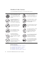
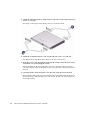
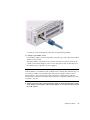
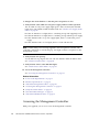
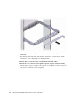
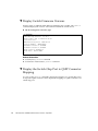
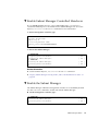
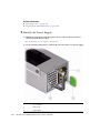
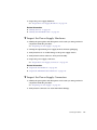
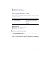
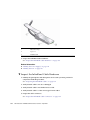
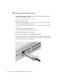
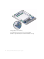
▼ Verify Shipping Carton Contents
1. Open the gateway shipping carton and any additional cartons.
Power cords and data cables are shipped separately.
2. Compare the contents to the following figure.
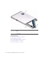
18
Item
Description
1
Switch
Sun Datacenter InfiniBand Switch 36 User’s Guide • April 2011
Item
Description
2
Front mounting brackets, long
3
Front mounting brackets, short
4
C-shaped brackets
5
Documentation
6
Hardware
7
Cable management extenders
8
Long rails
9
Cable management cover
10
Cable management assembly
11
Attachment brackets
12
Attachment plates
Power cords (not pictured)
3. After verifying the package contents, route the InfiniBand cables.
See “Route the InfiniBand Cables” on page 19.
Related Information
■
“Install the Switch in the Rack” on page 20
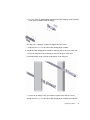
▼ Route the InfiniBand Cables
1. Identify the prerequisite and subsequent installation tasks that you must
perform in conjunction with this procedure.
See “Installation Sequence” on page 17.
2. At the remote hosts, begin attaching the InfiniBand cables to the appropriate
connectors.
3. Route and bundle the InfiniBand cables.
Follow the cautions and guidelines provided in “Understanding InfiniBand
Cabling” on page 9.
4. Bring the cables to the location in the rack where you are installing the switch.
Installing the Switch
19
5. Install the switch into the rack.
See “Install the Switch in the Rack” on page 20.
Related Information
■
“InfiniBand Cable Guidelines” on page 11
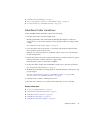
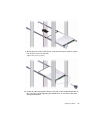
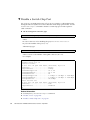
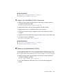
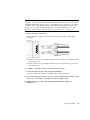
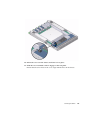
▼ Install the Switch in the Rack
Caution – The airflow through the switch is in from the fans, through the chassis,
and out at the connector panel. The front of the switch chassis (fan end) intakes from
the cold aisle. The rear of the switch chassis (connector end) exhausts to the hot aisle.
This flow direction requires you to install the switch in an orientation that is the
opposite of what you might assume.
1. Identify the prerequisite and subsequent installation tasks that you must
perform in conjunction with this procedure.
See “Installation Sequence” on page 17.
2. If installed, open the rack doors.
3. Assemble the cable management extenders.
a. Slide the attachment bracket over the extender, so that the tab on the bracket
is opposite the flange on the extender.
The open end of the tab is toward the flange. The flat end of the tab is toward
the rear of the extender.
b. Place the attachment plate on the flange side of the extender, opposite the
attachment bracket.
20
Sun Datacenter InfiniBand Switch 36 User’s Guide • April 2011
c. Use two screws to sandwich the attachment bracket and plate to the extender,
in the position farthest from the flange.
d. Using a No. 2 Phillips screwdriver, tighten the two screws.
e. Repeat from Step a for the other cable management extender.
4. Attach the cable management extenders and long rails to the rear of the rack.
a. Place the long rail to the mounting location on the post of the rack.
b. Butt the flange of the extender to the flange of the long rail.
c. Secure the assembly to the post with two captive nuts and two screws.
d. Repeat from Step a for the other cable management extender and long rail.
Installing the Switch
21
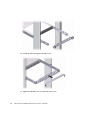
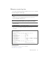
5. Attach the long front brackets (with cutouts) to the front of the switch with four
screws on each side.
The flange of the long front brackets point away from the switch.
6. Attach the C-shaped brackets to the switch with four screws on each side.
The edge of the C-shaped bracket is flush to the rear of the chassis.
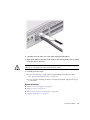
7. Route the power cords through the rack with the female end at the front of the
rack where you are installing the switch.
Ensure that there is 24 inches (610 mm) of power cord slack at the front of the
rack. This slack provides an adequate service loop when removing the switch from
the rack.
8. Carefully lift the switch and slide it into the rack, from the front rearward.
Ensure that the ends of the long rails slide into the C-shaped brackets at the rear of
the switch chassis and that the power cords fit into the cut-outs of the long front
mounting brackets.
22
Sun Datacenter InfiniBand Switch 36 User’s Guide • April 2011
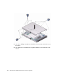
9. Mount the front of the switch chassis to the front rack posts with two captive
nuts and two screws at each side.
Tighten the screws securely.
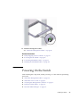
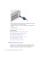
10. Install the cable management bracket to the tabs of the attachment brackets at
the rear of the switch, tightening the thumbscrews on each side of the cable
management bracket.
Installing the Switch
23
11. Install the cable management bracket cover.
12. Tighten the thumbscrews on each side of the cover.
24
Sun Datacenter InfiniBand Switch 36 User’s Guide • April 2011
13. Attach the management cables.
See “Attach the Management Cables” on page 26.
Related Information
■
“Verify Shipping Carton Contents” on page 18
■
“Powering On the Switch” on page 25
■
“Connecting InfiniBand Cables” on page 38
■
“Verifying the InfiniBand Fabric” on page 44
Powering On the Switch
After installing the components, enable powering on of the switch by performing
these tasks.
■
“Attach the Management Cables” on page 26
■
“Attach the Power Cords” on page 28
■
“Accessing the Management Controller” on page 31
■
“Verify the Switch Status” on page 34
■
“Start the Subnet Manager” on page 36
Installing the Switch
25
Related Information
■
“Understanding Switch Specifications” on page 1
■
“Routing Service Cables” on page 7
■
“Install the Switch in the Rack” on page 20
■
“Connecting InfiniBand Cables” on page 38
■
“Verifying the InfiniBand Fabric” on page 44
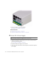
▼ Attach the Management Cables
The switch has two connectors for network or serial communication with the
management controller.
The network management connector, labeled NET, is a 100/100 BASE-T Ethernet
interface. This connector is preferred because it permits remote management of the
switch over the Ethernet network.
The USB management connector, labeled with the USB symbol, is the second choice
for communication with the management controller in the switch. The management
console can be a serial terminal, a system running a TIP connection, or other serial
device which communicates with the management controller through a USB-to-serial
adapter. The serial parameters for communication with the USB-to-serial adapter is
typically 115600, 8, N, 1.
1. Identify the prerequisite and subsequent installation tasks that you must
perform in conjunction with this procedure.
See “Installation Sequence” on page 17.
2. Connect an Ethernet cable between the switch NET0 port and the network that
is configured with a DHCP server.
26
Sun Datacenter InfiniBand Switch 36 User’s Guide • April 2011
Connections to the management controller are made through DHCP.
3. Configure your DHCP server.
Use the MAC address of the management controller to provide a host name and IP
address for the switch.
The MAC address is printed on the customer information (yellow) sheet on the
outside of the switch shipping carton and on the pull-out tab on the left front of
the switch chassis, adjacent to power supply 0.
Note – If a DHCP server is not available, the management controller has a default
static IP address of 169.254.0.36 with a subnet mask of 255.255.0.0. Alternatively, you
can connect a USB-to-serial adapter cable between the switch’s USB port and a
terminal device. This connection provides alternative communication with the
management controller. The terminal device must be configured 115200 baud, 8 bit,
no parity, 1 stop bit.
4. (Optional) Connect the serial management cables from the management console
to the USB-to-serial adapter, and from the adapter to the connector labeled with
the USB symbol.
Installing the Switch
27
5. Route the management cables so that they do not interfere with other cables,
with servicing the switch, or with other systems.
6. Prepare the management console for communication with the management
controller.
7. Power on the switch.
See “Attach the Power Cords” on page 28.
Related Information
■
“Network Management Connector and Pins” on page 4
■
“USB Management Connector and Pins” on page 5
■
“Management Cable Requirements” on page 8
■
“Attach the Power Cords” on page 28
■
“Accessing the Management Controller” on page 31
■
“Verify the Switch Status” on page 34
■
“Start the Subnet Manager” on page 36
■
“Attach the InfiniBand Cables” on page 38
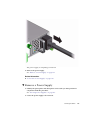
▼ Attach the Power Cords
The power cords for the switch ship separately and are specific to the country of
installation. See “Power Cord Requirements” on page 7. The facility power
receptacles for the power cords should be located such that the power cords are
routed out of the way, either to the sides of the rack or under the floor.
28
Sun Datacenter InfiniBand Switch 36 User’s Guide • April 2011
When live power is delivered to the receptacles at the front of the chassis, standby
and main power is made available by the power supplies. When standby power is
distributed to the chassis, the management controller is powered on. The main power
is supplied for the switch chip and fans.
1. Identify the prerequisite and subsequent installation tasks that you must
perform in conjunction with this procedure.
See “Installation Sequence” on page 17.
2. Ensure that the circuit breakers for the facility power are switched off.
3. Plug the power cords into the receptacles at the front of the switch chassis.
4. Route the end of each power cord to its respective facility power receptacle.
Use cable ties or hook and loop fastener straps to bundle and secure the cord.
5. Plug each power cord into the receptacle.
Note – To provide redundancy, connect each power cord to a separate power source.
The switch can operate with only one power connection, but there is no redundancy
in that case.
Installing the Switch
29
6. Energize the circuit breakers so that the power receptacles are live.
7. Verify that the status LEDs for each power supply indicate normal operation.
The AC LED on each power supply lights green. After a moment, the OK LED
lights green. The Attention LED should be unlit. See “Check Power Supply Status
LEDs” on page 60.
■
If the AC LED does not light, there is something wrong with supplied power.
■
If the OK LED does not light, there is something wrong with the power supply.
■
If the Attention LED on a power supply lights, there is a fault in the power
supply.
■
If the Attention LED on a fan lights, there is a fault with that fan.
Note – At this time, power is being supplied to the management controller. The
controller is effectively on and booting up. You might see the boot sequence on the
management console.
8. Verify that the fans spin up.
You should feel air going into the fans. The fan Attention LEDs should be unlit.
See “Check Fan Status LEDs” on page 60.
9. Verify that the chassis status OK LED lights.
See “Check Chassis Status LEDs” on page 58.
10. Access the management controller.
See “Accessing the Management Controller” on page 31.
Related Information
■
“Power Cord Requirements” on page 7
■
“Electrical Specifications” on page 4
■
“Attach the Management Cables” on page 26
■
“Accessing the Management Controller” on page 31
■
“Verify the Switch Status” on page 34
■
“Start the Subnet Manager” on page 36
■
“Attach the InfiniBand Cables” on page 38
Accessing the Management Controller
With power applied, you can now access the management controller.
30
Sun Datacenter InfiniBand Switch 36 User’s Guide • April 2011
■
“Access the Management Controller From the Network Management Port” on
page 31
■
“Access the Management Controller From the USB Management Port” on page 32
Related Information
■
“Network Management Connector and Pins” on page 4
■
“USB Management Connector and Pins” on page 5
■
“Management Cable Requirements” on page 8
■
“Attach the Management Cables” on page 26
■
“Attach the Power Cords” on page 28
■
“Verify the Switch Status” on page 34
■
“Start the Subnet Manager” on page 36
▼ Access the Management Controller From the Network
Management Port
Note – The administrator of the switch has the username of root.
1. Identify the prerequisite and subsequent installation tasks that you must
perform in conjunction with this procedure.
See “Installation Sequence” on page 17.
2. If you have not already done so, configure your DHCP server.
Use the MAC address of the management controller to provide a host name and IP
address for the switch.
See “Attach the Management Cables” on page 26.
3. Open an SSH session and connect to the management controller by specifying
the controller’s host name as configured with the DHCP server.
For example:
% ssh -l root nm2name
root@nm2name’s password: password
#
where nm2name is the host name of the management controller. The name might
be the word hostname. Initially, the password is changeme.
Installing the Switch
31
Note – You can change the password at a later time. See “Change the Administrator
Password” on page 98 for instructions on how to change the administrator password.
If you do not see this output or prompt, there is a problem with the DHCP
configuration, network management communication, or the management
controller.
4. Verify the switch status.
See “Verify the Switch Status” on page 34.
Related Information
■
“Network Management Connector and Pins” on page 4
■
“Management Cable Requirements” on page 8
▼ Access the Management Controller From the USB
Management Port
Note – The administrator of the switch has the username of root.
1. Identify the prerequisite and subsequent installation tasks that you must
perform in conjunction with this procedure.
See “Installation Sequence” on page 17.
2. If you have not already done so, connect a USB-to-serial adapter to the USB port
of the switch.
3. Connect a serial terminal, terminal server, or workstation with a TIP connection
to the USB-to-serial adapter.
Configure the terminal or terminal emulator with these settings:
32
■
115200 baud
■
8 bits
■
No parity
■
1 Stop bit
■
No handshaking
Sun Datacenter InfiniBand Switch 36 User’s Guide • April 2011
4. Press the Return or Enter key on the serial device several times to synchronize
the connection.
You might see text similar to the following:
...
CentOS release 5.2 (Final)
Kernel 2.6.27.13-nm2 on an i686
nm2name login:
where nm2name is the host name of the management controller. The name might
be the word hostname. Even if you do not see the text, go to Step 5.
5. Type root for the login name, followed by the root password of changeme.
nm2name login: root
Password: password
#
The # prompt is displayed.
Note – You can change the password at a later time. See “Change the Administrator
Password” on page 98 for instructions on how to change the administrator password.
If you do not see this output or prompt, there is a problem with the serial
configuration, the USB-to-serial adapter, or the management controller.
6. Verify the switch status.
See “Verify the Switch Status” on page 34.
Related Information
■
“USB Management Connector and Pins” on page 5
■
“Management Cable Requirements” on page 8
▼ Verify the Switch Status
You can use the following commands on the management controller to check the
status of the switch.
1. Identify the prerequisite and subsequent installation tasks that you must
perform in conjunction with this procedure.
See “Installation Sequence” on page 17.
Installing the Switch
33
2. Check the overall health of the switch:
# showunhealthy
OK - No unhealthy sensors
#
An unfavorable output from the showunhealthy command means a hardware
fault with that particular component.
3. Check the status of the power supplies:
# checkpower
PSU 0 present status: OK
PSU 1 present status: OK
#
A power supply output that is not OK from the checkpower command means that
there is a problem with that power supply. See “Check Power Supply Status
LEDs” on page 60 for assistance.
4. Check the status of the fans:
# getfanspeed
Fan 0 not present
Fan 1 running at rpm 11212
Fan 2 running at rpm 11313
Fan 3 running at rpm 11521
Fan 4 not present
#
■
A stopped or low speed in the output of the getfanspeed command means
there is a problem with that particular fan.
■
If not present is in the output of the getfanspeed command, yet a fan is
installed at that particular slot, there is a problem with that fan.
For either condition, check the fan. See “Servicing Fans” on page 125.
5. Check the status of the switch chip:
# checkboot
Switch OK
#
If the output of the checkboot command is not OK, there is a problem with the
switch chip. Try resetting the switch chip. See “Reset the Switch Chip” on page 94.
34
Sun Datacenter InfiniBand Switch 36 User’s Guide • April 2011
6. Alternatively, you can use the env_test command to perform the preceding
checks and more:
# env_test
Environment test started:
Starting Voltage test:
Voltage ECB OK
Measured 3.3V Main = 3.28 V
Measured 3.3V Standby = 3.37 V
Measured 12V = 12.06 V
Measured 5V = 5.03 V
Measured VBAT = 3.25 V
Measured 2.5V = 2.52 V
Measured 1.8V = 1.80 V
Measured I4 1.2V = 1.22 V
Voltage test returned OK
Starting PSU test:
PSU 0 present
PSU 1 present
PSU test returned OK
Starting Temperature test:
Back temperature 23.00
Front temperature 32.62
SP temperature 26.12
Switch temperature 34, maxtemperature 36
Temperature test returned OK
Starting FAN test:
Fan 0 not present
Fan 1 running at rpm 11212
Fan 2 running at rpm 11313
Fan 3 running at rpm 11521
Fan 4 not present
FAN test returned OK
Starting Connector test:
Connector test returned OK
Starting onboard ibdevice test:
Switch OK
All Internal ibdevices OK
onboard ibdevice test returned OK
Environment test PASSED
#
Note – If in the output of the env_test command a voltage deviates more than 10%
from the provided specification, there is a problem with the respective component.
Installing the Switch
35
7. Once the switch has an operational status, start the Subnet Manager.
See “Start the Subnet Manager” on page 36.
Related Information
■
Switch Reference, showunhealthy command
■
Switch Reference, checkpower command
■
Switch Reference, getfanspeed command
■
Switch Reference, checkboot command
■
Switch Reference, env_test command
■
“Attach the Management Cables” on page 26
■
“Attach the Power Cords” on page 28
■
“Accessing the Management Controller” on page 31
■
“Start the Subnet Manager” on page 36
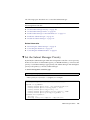
▼ Start the Subnet Manager
If you have no Subnet Managers other than the one within the management
controller, you need not set the Subnet Manager priority. If you have other Subnet
Managers in your InfiniBand fabric, you must decide which is to be the primary
Subnet Manager. The primary (or master) Subnet Manager has the highest priority.
All other Subnet Managers are secondary Subnet Managers, and must have a lower
priority.
1. Identify the prerequisite and subsequent installation tasks that you must
perform in conjunction with this procedure.
See “Installation Sequence” on page 17.
2. Enable the Subnet Manager:
# enablesm
Starting IB Subnet Manager.
#
3. (Optional) Configure the priority of the Subnet Manager within the
management controller.
36
Sun Datacenter InfiniBand Switch 36 User’s Guide • April 2011
[
OK
]
a. Set the priority of the Subnet Manager:
# setsmpriority priority
where priority is 0 (lowest) to 13 (highest). For example, to set the Subnet
Manager to priority 13:
# setsmpriority 13
------------------------------------------------OpenSM 3.2.6_20090717
Reading Cached Option File: /etc/opensm/opensm.conf
Loading Cached Option:routing_engine = ftree
Loading Cached Option:sminfo_polling_timeout = 1000
Loading Cached Option:polling_retry_number = 3
Command Line Arguments:
Priority = 13
Creating config file template ’/tmp/osm.conf’.
Log File: /var/log/opensm.log
------------------------------------------------#
b. Restart the Subnet Manager:
# disablesm
Stopping IB Subnet Manager.
# enablesm
Starting IB Subnet Manager.
#
[
OK
]
[
OK
]
4. Attach the InfiniBand cables.
See “Attach the InfiniBand Cables” on page 38.
Related Information
■
Switch Reference, setsmpriority command
■
Switch Reference, enablesm command
■
Switch Reference, opensm command
■
“Attach the Management Cables” on page 26
■
“Attach the Power Cords” on page 28
■
“Accessing the Management Controller” on page 31
■
“Verify the Switch Status” on page 34
Installing the Switch
37
Connecting InfiniBand Cables
After verifying the switch operational status, you can begin attaching the InfiniBand
cables.
■
“Attach the InfiniBand Cables” on page 38
■
“Check Link Status” on page 44
Related Information
■
“Understanding InfiniBand Cabling” on page 9
■
“Install the Switch in the Rack” on page 20
■
“Powering On the Switch” on page 25
■
“Verifying the InfiniBand Fabric” on page 44
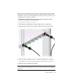
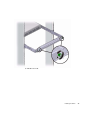
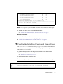
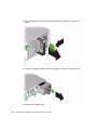
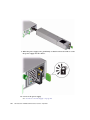
▼ Attach the InfiniBand Cables
Caution – InfiniBand cables must never turn tighter than a 5-inch (127 mm) radius.
A tighter radius damages the wires and fibers inside the cable.
Note – When you install the InfiniBand cables, connect cables to the lower
connectors first. Then connect cables to the upper connectors.
1. Identify the prerequisite and subsequent installation tasks that you must
perform in conjunction with this procedure.
See “Installation Sequence” on page 17.
2. Loosen the two captive thumbscrews that secure the cover to the cable
management bracket.
38
Sun Datacenter InfiniBand Switch 36 User’s Guide • April 2011
3. Lift the cover off.
Installing the Switch
39
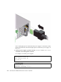
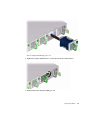
4. Remove the protective cap from the connector and visually inspect the cable
connector.
The shell should not be bent and should be parallel to the inner boards. If the
connector is bent or damaged, use a different cable.
5. Ensure that the retraction strap is folded back against the cable.
6. Orient the cable connector to the QSFP receptacle squarely and horizontally.
Ensure that the L groove is up for the top row of receptacles, or that the L groove
is down for the bottom row of receptacles.
40
Sun Datacenter InfiniBand Switch 36 User’s Guide • April 2011
Note – On some QSFP cable connectors, there is a retraction strap. Both the
retraction strap and L groove indicate the reference surface for the connector. When
installing QSFP cables in the top row of receptacles (0A, 1A, 2A, and so on), ensure
that the L groove and retraction strap are up. When installing QSFP cables in the
bottom row of receptacles (0B, 1B, 2B, and so on), ensure that the L groove and
retraction strap are down. See “Identify the InfiniBand Cable” on page 133.
7. Slowly move the connector in.
As you slide the connector in, the shell should be in the center of the QSFP
receptacle.
■
If the connector stops or binds after about 1/4 in. (5 mm) travel, back out and
repeat from Step 6.
Installing the Switch
41
■
If the connector stops or binds with about 1/8 in. (2 mm) still to go, back out
and repeat Step 7.
8. Continue to push the connector in until you feel a detent.
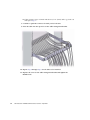
9. Place the cable into the open slot on the cable management bracket.
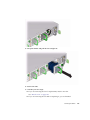
10. Repeat Step 4 through Step 9 for all cables to be installed.
11. Replace the cover for the cable management bracket and tighten the
thumbscrews.
42
Sun Datacenter InfiniBand Switch 36 User’s Guide • April 2011
12. Route the InfiniBand cables so that they do not interfere with other cables, or
with servicing the switch or other systems.
Use hook and loop fastener straps to bundle and secure the cables.
Note – Do not use cable zip ties to bundle or secure the cable, because the ties
damage the fibers inside the cable.
13. Check that the Link LEDs for cabled links are lit green.
If the Link LED is unlit, the link is down. If the Link LED flashes, there are symbol
errors. See “Check Link Status LEDs” on page 59.
14. If possible, close the rack doors to maintain EMI compliance.
15. Check the link status.
See “Check Link Status” on page 44.
Related Information
■
“Understanding InfiniBand Cabling” on page 9
■
“Attach the Management Cables” on page 26
■
“Attach the Power Cords” on page 28
■
“Check Link Status” on page 44
Installing the Switch
43
▼ Check Link Status
1. Identify the prerequisite and subsequent installation tasks that you must
perform in conjunction with this procedure.
See “Installation Sequence” on page 17.
2. On the management controller, determine the state of the links:
# listlinkup
■
If the link for a connector is reported as Not present, there is no cable
attached, or the link at either end of the cable is down.
■
If a port is down, use the enableswitchport command to bring the port up.
Alternatively, use the ibdevreset command to reset the entire switch chip.
See “Enable a Switch Chip Port” on page 97 and “Reset the Switch Chip” on
page 94.
3. Verify the InfiniBand fabric.
See “Discover the InfiniBand Fabric Topology” on page 45.
Related Information
■
Switch Reference, listlinkup command
■
Switch Reference, enableswitchport command
■
Switch Reference, ibdevreset command
■
“Verify the Switch Status” on page 34
■
“InfiniBand Cable Cautions” on page 10
■
“InfiniBand Cable Guidelines” on page 11
■
“Attach the InfiniBand Cables” on page 38
Verifying the InfiniBand Fabric
Use the ibnetdiscover, ibdiagnet, and ibcheckerrors commands to initially
determine the operational status of your switch in the InfiniBand fabric.
44
■
“Discover the InfiniBand Fabric Topology” on page 45
■
“Perform Diagnostics on the InfiniBand Fabric” on page 46
■
“Validate the InfiniBand Fabric and Report Errors” on page 47
Sun Datacenter InfiniBand Switch 36 User’s Guide • April 2011
Related Information
■
“Install the Switch in the Rack” on page 20
■
“Powering On the Switch” on page 25
■
“Connecting InfiniBand Cables” on page 38
▼ Discover the InfiniBand Fabric Topology
The ibnetdiscover command enables you to see the InfiniBand fabric topology
and build a topology file, which is used by the OpenSM Subnet Manager.
1. Identify the prerequisite and subsequent installation tasks that you must
perform in conjunction with this procedure.
See “Installation Sequence” on page 17.
2. On the management controller, type:
# ibnetdiscover
#
# Topology file: generated on Sat Apr 13 22:28:55 2002
#
# Max of 1 hops discovered
# Initiated from node 0021283a8389a0a0 port 0021283a8389a0a0
vendid=0x2c9
devid=0xbd36
sysimgguid=0x21283a8389a0a3
switchguid=0x21283a8389a0a0(21283a8389a0a0)
Switch 36 "S-0021283a8389a0a0" # "Sun DCS 36 QDR switch localhost" enhanced port
0 lid 15 lmc 0
[23]
"H-0003ba000100e388"[2](3ba000100e38a) # "nsn33-43 HCA-1" lid 14 4xQDR
vendid=0x2c9
devid=0x673c
sysimgguid=0x3ba000100e38b
caguid=0x3ba000100e388
Ca
2 "H-0003ba000100e388" # "nsn33-43 HCA-1"
[2](3ba000100e38a)
"S-0021283a8389a0a0"[23] # lid 14 lmc 0 "Sun DCS 36 QDR
switch localhost" lid 15 4xQDR
#
Note – The output for your InfiniBand fabric will differ from that in the example.
3. Perform InfiniBand fabric diagnostics.
See “Perform Diagnostics on the InfiniBand Fabric” on page 46.
Installing the Switch
45
Related Information
■
Switch Reference, ibnetdiscover command
■
“Perform Diagnostics on the InfiniBand Fabric” on page 46
■
“Validate the InfiniBand Fabric and Report Errors” on page 47
▼ Perform Diagnostics on the InfiniBand Fabric
The ibdiagnet command performs a collection of tests on the InfiniBand fabric and
generates several files that contain parameters and aspects of the InfiniBand fabric.
1. Identify the prerequisite and subsequent installation tasks that you must
perform in conjunction with this procedure.
See “Installation Sequence” on page 17.
2. On the management controller, type:
# ibdiagnet
In the following example, the ibdiagnet command is minimized to determine
which links are underperforming:
# ibdiagnet -lw 4x -ls 10 -skip all
Loading IBDIAGNET from: /usr/lib/ibdiagnet1.2
-W- Topology file is not specified.
Reports regarding cluster links will use direct routes.
Loading IBDM from: /usr/lib/ibdm1.2
-I- Using port 0 as the local port.
-I- Discovering ... 2 nodes (1 Switches & 1 CA-s) discovered.
.
.
.
-I- Links With links width != 4x (as set by -lw option)
-I---------------------------------------------------I- No unmatched Links (with width != 4x) were found
-I---------------------------------------------------I- Links With links speed != 10 (as set by -ls option)
-I---------------------------------------------------I- No unmatched Links (with speed != 10) were found
.
.
.
-I- Stages Status Report:
STAGE
Errors Warnings
Bad GUIDs/LIDs Check
0
0
46
Sun Datacenter InfiniBand Switch 36 User’s Guide • April 2011
Link State Active Check
0
0
Performance Counters Report
0
0
Specific Link Width Check
0
0
Specific Link Speed Check
0
0
Partitions Check
0
0
IPoIB Subnets Check
0
0
Please see /tmp/ibdiagnet.log for complete log
----------------------------------------------------------------I- Done. Run time was 1 seconds.
#
Note – The output for your InfiniBand fabric will differ from that in the example.
3. Validate and check errors for the InfiniBand fabric.
See “Validate the InfiniBand Fabric and Report Errors” on page 47.
Related Information
■
Switch Reference, ibdiagnet command
■
“Discover the InfiniBand Fabric Topology” on page 45
■
“Validate the InfiniBand Fabric and Report Errors” on page 47
▼ Validate the InfiniBand Fabric and Report Errors
The ibcheckerrors command uses the topology file to scan the InfiniBand fabric
and validate the connectivity as described in the topology file, and to report errors as
indicated by the port counters.
1. Identify the prerequisite and subsequent installation tasks that you must
perform in conjunction with this procedure.
See “Installation Sequence” on page 17.
2. On the management controller, type:
Note – The output for your InfiniBand fabric will differ from that in the example.
# ibcheckerrors
## Summary: 4 nodes checked, 0 bad nodes found
##
34 ports checked, 0 ports have errors beyond threshold
#
Installing the Switch
47
Note – The thresholds are dependent of time since the last reset. If you see a lot of
errors, reset the counters with the ibclearerrors command. Check the errors a
few minutes later with the ibcheckerrors command.
Related Information
48
■
Switch Reference, ibcheckerrors command
■
“Discover the InfiniBand Fabric Topology” on page 45
■
“Perform Diagnostics on the InfiniBand Fabric” on page 46
Sun Datacenter InfiniBand Switch 36 User’s Guide • April 2011
Administering the Switch
The following topics describe the administration of the switch.
■
“Troubleshooting the Switch” on page 49
■
“Understanding Administrative Commands” on page 65
■
“Monitoring the Hardware” on page 67
■
“Monitoring the InfiniBand Fabric” on page 80
■
“Monitoring the Subnet Manager” on page 89
■
“Controlling the Hardware” on page 92
■
“Controlling the InfiniBand Fabric” on page 98
■
“Controlling the Subnet Manager” on page 108
Related Information
■
“Installing the Switch” on page 1
■
“Servicing the Switch” on page 113
■
Switch Remote Administration
■
Switch Reference
Troubleshooting the Switch
The following topics help you resolve some basic problems that might occur with
your switch.
■
“Switch Hardware Problems” on page 50
■
“InfiniBand Fabric Problems” on page 53
■
“Identifying LEDs” on page 56
■
“Understanding Routing Through the Switch” on page 61
■
“Switch GUIDs Overview” on page 64
49
Related Information
■
“Understanding Administrative Commands” on page 65
■
“Monitoring the Hardware” on page 67
■
“Monitoring the InfiniBand Fabric” on page 80
■
“Monitoring the Subnet Manager” on page 89
■
“Controlling the Hardware” on page 92
■
“Controlling the InfiniBand Fabric” on page 98
■
“Controlling the Subnet Manager” on page 108
Switch Hardware Problems
The following table lists situations that might occur with switch hardware and
corrective steps that you can take to resolve the problem.
Situation
Corrective Steps
The Attention LED on a 1. Check the power supply status.
power supply is lit or the
See “Display Power Supply Status” on page 69.
power supply seems
2. Unplug the respective power cord, wait 15 minutes, then reattach the power cord.
dysfunctional.
3. If the previous steps do not rectify the situation, replace the power supply.
See “Servicing Power Supplies” on page 115.
There is no network
communication with the
management controller.
50
1. Verify that the management controller is powered without faults.
See “Check Chassis Status LEDs” on page 58.
2. Verify that there is a LinkUp condition at the network management port.
See “Check Network Management Port Status LEDs” on page 59.
3. Verify that the DHCP server is providing the IP address you are using to access the
management controller.
See DHCP server documentation.
4. If you are able to access the management controller through the USB connector,
restart the management controller.
See “Access the Management Controller From the USB Management Port” on
page 32 and “Restart the Management Controller” on page 92.
5. If you are unable to access the management controller through the USB connector,
power cycle the switch.
See “Power Off a Power Supply” on page 118 and “Power On a Power Supply” on
page 123.
6. If the previous steps do not rectify the situation, replace the switch.
See “Remove the Switch From the Rack” on page 140 and “Installing the Switch”
on page 1.
Sun Datacenter InfiniBand Switch 36 User’s Guide • April 2011
Situation
Corrective Steps
The Attention LED on
1. If you are unable to access the management controller, power cycle the switch.
the switch chassis is lit or
See “Power Off a Power Supply” on page 118 and “Power On a Power Supply” on
the management
page 123.
controller seems
2. If you are able to access the management controller, restart the management
dysfunctional.
controller.
See “Restart the Management Controller” on page 92.
3. Check overall switch health.
See “Display the State of the Chassis Status LEDs” on page 68
4. Verify that the switch is within operating temperatures and voltages.
See “Display Switch Environmental and Operational Data” on page 72.
5. If the previous steps do not rectify the situation, replace the switch.
See “Remove the Switch From the Rack” on page 140 and “Installing the Switch”
on page 1.
The Attention LED on a 1. Check the fan speed.
fan is lit or the fan seems
See “Display Fan Status” on page 71.
dysfunctional.
2. If the previous step does not rectify the situation, replace the fan.
See “Servicing Fans” on page 125.
3. If the previous step does not rectify the situation, install the fan into another
available slot.
See “Servicing Fans” on page 125
4. If no other slots are available, replace the switch.
See “Remove the Switch From the Rack” on page 140 and “Installing the Switch”
on page 1.
After installation, no
links are operational.
1. Verify that there is at least one Subnet Manager active on the InfiniBand Fabric.
See “Display Subnet Manager Status” on page 89.
2. If no Subnet Manager is active, start the Subnet Manager within the switch.
See “Start the Subnet Manager” on page 36.
3. If the previous steps do not rectify the situation, restart the Subnet Manager.
See “Disable the Subnet Manager” on page 112 and “Enable the Subnet Manager”
on page 111.
After installation, not all
links are operational.
1. Determine which links are nonoperational.
See “Display Link Status” on page 77.
2. For links that are Down, disable and re-enable the respective ports.
See “Disable a Switch Chip Port” on page 96 and “Enable a Switch Chip Port” on
page 97.
3. If the previous steps do not rectify the situation, disable the respective port.
See “Disable a Switch Chip Port” on page 96.
Administering the Switch
51
Situation
Corrective Steps
There was a power
outage during a
firmware update.
1. If you are able to access the management controller, restart the management
controller.
See “Restart the Management Controller” on page 92.
2. If you are unable to access the management controller, power cycle the switch.
See “Power Off a Power Supply” on page 118 and “Power On a Power Supply” on
page 123.
3. Reperform the firmware upgrade.
See “Firmware Upgrades” on page 146.
Related Information
52
■
“InfiniBand Fabric Problems” on page 53
■
“Identifying LEDs” on page 56
■
“Understanding Routing Through the Switch” on page 61
■
“Switch GUIDs Overview” on page 64
Sun Datacenter InfiniBand Switch 36 User’s Guide • April 2011
InfiniBand Fabric Problems
The following table lists situations that might occur with the InfiniBand fabric and
corrective steps that you can take to resolve the problem.
Situation
Corrective Steps
Performance of the
InfiniBand fabric
seems diminished.
1. Determine if there are errors or problems with the InfiniBand fabric.
See:
“Perform Comprehensive Diagnostics for the Entire Fabric” on page 99
“Find 1x, SDR, or DDR Links in the Fabric” on page 101
“Determine Which Links Are Experiencing Significant Errors” on page 102
2. Locate the affected nodes by the GUID provided in the output of the ibdiagnet
command.
See “Locate a Switch Chip or Connector From the GUID” on page 76.
3. If the problem is at a cable connection, swap the suspect cable with a known good cable
or reconnect the cable to a known good remote port and repeat Step 1.
See “Servicing InfiniBand Cables” on page 132.
4. If the problem still remains at the cable connection, disable and re-enable the respective
port and repeat Step 1.
See “Disable a Port” on page 106 and “Enable a Port” on page 107.
Temporary solution:
• If the problem still remains, disable the affected port.
See “Disable a Port” on page 106.
Permanent solution:
• If the problem still remains, replace the affected component or the switch.
See “Servicing InfiniBand Cables” on page 132.
See remote port’s documentation for replacement procedures.
See “Remove the Switch From the Rack” on page 140 and “Installing the Switch” on
page 1.
Administering the Switch
53
Situation
Corrective Steps
An InfiniBand Link
LED is blinking.
1. Disconnect and properly reconnect both ends of the respective InfiniBand cable.
See Switch Service, servicing an InfiniBand cable.
2. If the LED is still blinking, determine the significance of the errors through use of the
ibdiagnet command.
See “Determine Which Links Are Experiencing Significant Errors” on page 102.
3. Determine which connectors map to the affected link by deconstructing the node’s
GUID and port.
See “Locate a Switch Chip or Connector From the GUID” on page 76.
4. If some of the links are running at 1x or SDR, use that situation elsewhere in this table
to rectify the problem.
5. Disable and re-enable the respective ports.
See “Disable a Port” on page 106 and “Enable a Port” on page 107.
6. If the errors are still significant, swap the cable with a known good one or reconnect the
cable to a known good remote port, and repeat from 2.
7. Depending upon what does or does not rectify the problem, replace that component.
See “Servicing InfiniBand Cables” on page 132.
See the remote port’s documentation for replacement procedures.
54
Sun Datacenter InfiniBand Switch 36 User’s Guide • April 2011
Situation
Corrective Steps
Some InfiniBand
links are running at
1x or SDR.
For a temporary solution:
1. Identify the suspect links using the ibdiagnet command.
See “Find 1x, SDR, or DDR Links in the Fabric” on page 101. Look for text like the
following:
-W- link with SPD=2.5 found at direct path "1,19"
From: a Switch PortGUID=0x00066a00d80001dd Port=19
To:
a Switch PortGUID=0x00066a00d80001dd Port=24
2. Determine which connectors map to the affected link by deconstructing the node’s
GUID and port.
See “Locate a Switch Chip or Connector From the GUID” on page 76.
3. Verify the cable connection at both ends.
See “Servicing InfiniBand Cables” on page 132.
4. Disable and re-enable the respective ports.
See “Disable a Port” on page 106 and “Enable a Port” on page 107.
5. If the previous steps do not rectify the problem, disable the port.
See “Disable a Port” on page 106.
For a permanent solution:
1. Perform the steps for a temporary solution, steps 1 to step 4.
2. Swap the cable with a known good one or reconnect the cable to a known good remote
port, and repeat from Step 1.
3. Depending upon what does or does not rectify the problem, replace that component or
the switch.
See “Servicing InfiniBand Cables” on page 132.
See the remote port’s documentation for replacement procedures.
See “Remove the Switch From the Rack” on page 140 and “Installing the Switch” on
page 1.
There are errors on
some InfiniBand
links.
1. Clear the error counters.
See “Clear Error Counters” on page 103.
2. Start a fabric stress test.
3. Identify the suspect links using the ibdiagnet command.
See “Determine Which Links Are Experiencing Significant Errors” on page 102. Look
for text like the following:
-W- lid=0x0006 guid=0x0021283a8816c0a0 dev=48438 Port=34
Performance Monitor counter : Value
link_recovery_error_counter : 0x1
symbol_error_counter : 0x25 (Increase by 3 during ibdiagnet)
4. For links that are experiencing recovery errors or substantial symbol errors, see other
parts of this table to help identify the cause and rectify the problem.
Administering the Switch
55
Situation
Corrective Steps
Output of
1. Find the location of a node in the switch, by deconstructing the node’s GUID and port.
InfiniBand
See “Locate a Switch Chip or Connector From the GUID” on page 76.
commands provides 2. Use the dcsport command to provide a mapping of port-to-connector or
only GUID and port,
connector-to-port.
not switch chip or
See “Display the Switch Chip Port to QSFP Connector Mapping” on page 75.
QSFP connectors.
Related Information
■
“Switch Hardware Problems” on page 50
■
“Identifying LEDs” on page 56
■
“Understanding Routing Through the Switch” on page 61
■
“Switch GUIDs Overview” on page 64
Identifying LEDs
Status LEDs are used on many components of the switch chassis as a means of
indicating the component’s state.
■
“Front Status LEDs” on page 57
■
“Rear Status LEDs” on page 57
■
“Check Chassis Status LEDs” on page 58
■
“Check Network Management Port Status LEDs” on page 59
■
“Check Link Status LEDs” on page 59
■
“Check Power Supply Status LEDs” on page 60
■
“Check Fan Status LEDs” on page 60
Related Information
56
■
“Switch Hardware Problems” on page 50
■
“InfiniBand Fabric Problems” on page 53
■
“Understanding Routing Through the Switch” on page 61
■
“Switch GUIDs Overview” on page 64
Sun Datacenter InfiniBand Switch 36 User’s Guide • April 2011
Front Status LEDs
1
Power supply AC LED
2
Power supply Attention LED
3
Power supply OK LED
4
Fan Attention LED
Related Information
■
“Check Power Supply Status LEDs” on page 60
■
“Check Fan Status LEDs” on page 60
Rear Status LEDs
1
NET status LEDs
2
Link status LEDs
Administering the Switch
57
3
Chassis status LEDs
Related Information
■
“Check Chassis Status LEDs” on page 58
■
“Check Network Management Port Status LEDs” on page 59
■
“Check Link Status LEDs” on page 59
▼ Check Chassis Status LEDs
The chassis status LEDs are located on the left side of the rear panel. See “Rear Status
LEDs” on page 57.
1. Visually inspect the chassis status LEDs.
2. Compare what you see to the following table.
Icon
Location
Name
Color
State and Meaning
Top
Locator
White
On – No function.
Off – Disabled.
Flashing – The switch is identifying itself.
Middle
Attention
Amber
On – Normal fault detected.
Off – No faults detected.
Flashing – No function.
Bottom
OK
Green
On – Switch is functional without fault.
Off – Switch is off or initializing.
Flashing – No function.
Related Information
■
Switch Reference, chassis_led command
■
“Display Switch Environmental and Operational Data” on page 72
▼ Check Network Management Port Status LEDs
The network management port status LEDs are located on the network management
connector of the rear panel. See “Rear Status LEDs” on page 57.
1. Visually inspect the NET status LEDs.
58
Sun Datacenter InfiniBand Switch 36 User’s Guide • April 2011
2. Compare what you see to the following table.
Name
Position
Color
State
Link speed
Left
Amber or green
Amber on – 100BASE-T.
Green on – 1000BASE-T.
Off – No link or link down.
Flashing – No function.
Activity
Right
Green
On – No function.
Off – No activity.
Flashing – Packet activity.
▼ Check Link Status LEDs
The link status LEDs are located at the InfiniBand connectors of the rear panel. See
“Rear Status LEDs” on page 57.
1. Visually inspect the link status LEDs.
2. Compare what you see for a particular link to the following table.
Name
Color
State and Meaning
Link
Green
On – Link established.
Off – No link or link down.
Flashing – Symbol errors.
Related Information
■
“Display Link Status” on page 77
■
“Display the Link Status of a Node” on page 83
■
“Display Counters for a Node” on page 85
▼ Check Power Supply Status LEDs
The power supply status LEDs are located on the power supply at the front of the
chassis. See “Front Status LEDs” on page 57.
1. Visually inspect the power supply’s status LEDs.
Administering the Switch
59
2. Compare what you see on the power supply to the following table.
Icon
Location
Name
Color
State and Meaning
Top
OK
Green
On – 12 VDC is supplied.
Off – No DC voltage is present.
Flashing – No function.
Middle
Attention
Amber
On – Fault detected, 12 VDC shut down.
Off – No faults detected.
Flashing – No function.
Bottom
AC
Green
On – AC power present and good.
Off – AC power not present.
Flashing – No function.
Caution – If a power supply has shut down because of a thermal or overcurrent
condition, signified by the amber Attention LED lighting, remove the respective
power cord from the chassis. Allow the power supply to completely cool for at least
15 minutes. A shorter cooling time might cause damage to the power supply when
the power cord is reattached. If the Attention LED lights amber upon reattaching the
power cord, replace the power supply.
Related Information
■
“Display Power Supply Status” on page 69
■
“Check Board-Level Voltages” on page 70
▼ Check Fan Status LEDs
The fan status LEDs are located in the lower right corner of the fans at the front of
the switch chassis. See “Front Status LEDs” on page 57.
1. Visually inspect the fan status LEDs.
2. If the LED is lit, there is a problem with that fan.
Related Information
■
60
“Display Fan Status” on page 71
Sun Datacenter InfiniBand Switch 36 User’s Guide • April 2011
Understanding Routing Through the Switch
The tables in the following topics describe the routing through the switch. The first
table maps the switch chip port to a QSFP connector. The second table provides a
reverse map. When command output provides a switch chip port, you can use these
tables to determine the route that link is following.
■
“Switch Chip Port to QSFP Connectors and Link LED Routes” on page 62
■
“QSFP Connectors and Link LEDs to Switch Chip Port Routes” on page 62
■
“Signal Route Through the Switch” on page 63
Related Information
■
“Switch Hardware Problems” on page 50
■
“InfiniBand Fabric Problems” on page 53
■
“Identifying LEDs” on page 56
■
“Switch GUIDs Overview” on page 64
Switch Chip Port to QSFP Connectors and Link LED
Routes
Port
Connector
Port
Connector
Port
Connector
Port
Connector
1
17A
10
13B
19
0B
28
4A
2
17B
11
12A
20
0A
29
5B
3
16A
12
12B
21
1B
30
5A
4
16B
13
9B
22
1A
31
8A
5
15A
14
9A
23
2B
32
8B
6
15B
15
10B
24
2A
33
7A
7
14A
16
10A
25
3B
34
7B
8
14B
17
11B
26
3A
35
6A
9
13A
18
11A
27
4B
36
6B
Related Information
■
“Display the Switch Chip Port to QSFP Connector Mapping” on page 75
■
“Display Link Status” on page 77
■
“Display Switch Chip Port Status” on page 78
Administering the Switch
61
■
“QSFP Connectors and Link LEDs to Switch Chip Port Routes” on page 62
■
“Signal Route Through the Switch” on page 63
QSFP Connectors and Link LEDs to Switch Chip Port
Routes
The following table provides a mapping of the QSFP connector and its link LED to
the respective switch chip port.
Connector
Group
Connector
A Port
Connector
B Port
Connector
Group
Connector
A Port
Connector
B Port
0
20
19
9
14
13
1
22
21
10
16
15
2
24
23
11
18
17
3
26
25
12
11
12
4
28
27
13
9
10
5
30
29
14
7
8
6
35
36
15
5
6
7
33
34
16
3
4
8
31
32
17
1
2
Related Information
■
“Display the Switch Chip Port to QSFP Connector Mapping” on page 75
■
“Display Link Status” on page 77
■
“Display Switch Chip Port Status” on page 78
■
“Switch Chip Port to QSFP Connectors and Link LED Routes” on page 62
■
“Signal Route Through the Switch” on page 63
Signal Route Through the Switch
By combining the information from the tables in “Switch Chip Port to QSFP
Connectors and Link LED Routes” on page 62 and “QSFP Connectors and Link LEDs
to Switch Chip Port Routes” on page 62, it is possible to determine a route through
the switch. This topic describes a sample situation that might occur.
1. A route is initiated at connector 2A. The LED blinks.
62
Sun Datacenter InfiniBand Switch 36 User’s Guide • April 2011
2. Using “QSFP Connectors and Link LEDs to Switch Chip Port Routes” on page 62,
it is determined that the link routes to the switch chip through port 24.
3. The Subnet Manager instructs the switch chip to use port 4 to forward the link.
4. Using “Switch Chip Port to QSFP Connectors and Link LED Routes” on page 62, it
is determined that the link routes to connector 16B. The LED blinks.
Related Information
■
“Switch Chip Port to QSFP Connectors and Link LED Routes” on page 62
■
“QSFP Connectors and Link LEDs to Switch Chip Port Routes” on page 62
■
“Display the Switch Chip Port to QSFP Connector Mapping” on page 75
■
“Display a Route Through the Fabric” on page 83
■
“Perform Comprehensive Diagnostics for a Route” on page 99
Switch GUIDs Overview
Global unit identifiers (GUIDs) are unique 64-bit strings that identify nodes such as
switches and channel adapters. For the Sun Datacenter InfiniBand switches, GUIDs
are modified to identify the node’s role and location. The following table describes
the GUID’s structure.
63
16
MAC (48 bits)
15 12 11 8
7
Type
Device
Pos
4
3
0
Num
The five fields of the GUID are described as follows:
■
MAC – Bits 63 through 16 are the MAC address. A standard for network
components, the MAC address is typically provided by manufacturers in a 6-byte,
colon delimited string. For example, 00:11:22:33:44:55.
■
Type – Bits 15 through 12 are the type of board on which the node resides.
■
Pos – Bits 11 through 8 identify the position of the board within the switch.
■
Device – Bits 7 through 4 identify which device on the board has that node.
■
Num – Bits 3 through 0 are numbers reserved for the programs that modify the
GUID. In most occurrences, the value is 0x2.
The following table provides values for Type, Pos, Device.
Board
Type
Position
Device
Fabric card
0xF
0x0 (Fabric card 0) – 0x8 (Fabric card 8)
0xA (I4 chip 0) – 0xB (I4 chip 1)
Administering the Switch
63
Board
Type
Position
Device
Line card
0x1
0x0 (Line card 0) – 0x8 (Line card 8)
0xA (I4 chip 0) – 0xD (I4 chip 3)
Gateway
0xC
0x0
0xA (I4 chip 0), 0x0 (BX chip 0), 0x4
(BX chip 1)
36-port
0xA
0x0
0xA (I4 chip 0)
72-port
0xB
0x0
0xA (I4 chip 0) – 0xF (I4 chip 5)
For example, given the following output from the ibswitches command:
[16] -> switch port {0x0021283a831da0a2}[21] lid 214-214 "Sun DCS 36 QDR FC
switch 2.0"
The GUID is 0x0021283a831da0a2 or 0021283A831D A 0 A 2. Using the information
provided in this topic:
■
The MAC address is 0x0021283A831D or 00:21:28:3A:83:1D.
■
The type is 0xA, or a 36-port board.
■
The position is 0x0.
■
The device is 0xA, or a solitary I4 chip.
■
The number is 2.
Related Information
64
■
Switch Reference, ibnetdiscover command
■
Switch Reference, ibnodes command
■
Switch Reference, ibswitches command
■
Switch Reference, ibhosts command
■
“Identify All Switches in the Fabric” on page 80
■
“Switch Hardware Problems” on page 50
■
“InfiniBand Fabric Problems” on page 53
■
“Identifying LEDs” on page 56
■
“Understanding Routing Through the Switch” on page 61
Sun Datacenter InfiniBand Switch 36 User’s Guide • April 2011
Understanding Administrative
Commands
The following topics provide an overview of administrative tasks and the command
sets to perform those tasks. Administering the switch requires accessing the
management controller.
■
“Hardware Command Overview” on page 66
■
“InfiniBand Command Overview” on page 66
■
“ILOM Command Overview” on page 66
Related Information
■
“Troubleshooting the Switch” on page 49
■
“Monitoring the Hardware” on page 67
■
“Monitoring the InfiniBand Fabric” on page 80
■
“Monitoring the Subnet Manager” on page 89
■
“Controlling the Hardware” on page 92
■
“Controlling the InfiniBand Fabric” on page 98
■
“Controlling the Subnet Manager” on page 108
Hardware Command Overview
The management controller uses a simplified Linux OS and file system. From the #
prompt on the management controller, you can type hardware commands to perform
some administrative and management tasks. Hardware commands are user-friendly
and can perform some testing upon the switch chip, enabling greater control of the
switch and its operation.
After you log in to the root account, the shell prompt (#) appears, and you can enter
shell commands. Enter the hardware commands in the following format:
# command [arguments][arguments]...
Related Information
■
Switch Reference, understanding hardware commands
■
“InfiniBand Command Overview” on page 66
■
“ILOM Command Overview” on page 66
Administering the Switch
65
InfiniBand Command Overview
The InfiniBand commands are a means of monitoring and controlling aspects of the
InfiniBand fabric. These commands are also installed on and run from the
management controller, which is also the host of the Subnet Manager. Use of these
commands requires thorough knowledge of InfiniBand architecture and technology.
After you log in to the root account, the shell prompt (#) appears, and you can enter
shell commands. Enter the InfiniBand commands in the following format:
# command [option][option] ...
Related Information
■
Switch Reference, understanding InfiniBand commands
■
“Hardware Command Overview” on page 66
■
“ILOM Command Overview” on page 66
ILOM Command Overview
When you upgrade the management controller firmware to version 1.1.3 or higher,
Oracle ILOM 3.0 support is also installed. The Oracle ILOM CLI, web, SNMP, and
IPMI interfaces enable additional administration features and capabilities. The Oracle
ILOM CLI, SNMP, and IPMI interfaces use remote clients for command-line
administration of many Oracle ILOM targets. Alternatively, the Oracle ILOM web
interface permits point-and-click administration of the Oracle ILOM components and
services.
After you log in to the ilom-admin account, the Oracle ILOM prompt (->) appears,
and you can enter Oracle ILOM commands. Enter the Oracle ILOM commands in the
following format:
-> command [option][target][property=value]...
Information about Oracle ILOM support of the switch is available in the Oracle
Integrated Lights Out Manager (ILOM) 3.0 Supplement for the Sun Datacenter InfiniBand
Switch 36, available online at:
(http://www.oracle.com/pls/topic/lookup?ctx=E19197-01&id=
homepage)
Overall information about Oracle ILOM 3.0 is available online at:
(http://www.oracle.com/pls/topic/lookup?ctx=E19860-01&id=
homepage)
66
Sun Datacenter InfiniBand Switch 36 User’s Guide • April 2011
Related Information
■
Switch Remote Access, understanding the Oracle ILOM commands
■
“Hardware Command Overview” on page 66
■
“InfiniBand Command Overview” on page 66
Monitoring the Hardware
The following topics enable you to display and check the operation and status of the
switch.
■
“Display Switch General Health” on page 68
■
“Display the State of the Chassis Status LEDs” on page 68
■
“Display Power Supply Status” on page 69
■
“Check Board-Level Voltages” on page 70
■
“Display Internal Temperatures” on page 71
■
“Display Fan Status” on page 71
■
“Display Switch Environmental and Operational Data” on page 72
■
“Display Chassis FRU ID” on page 73
■
“Display Power Supply FRU ID” on page 73
■
“Display Switch Firmware Versions” on page 74
■
“Display the Switch Chip Port to QSFP Connector Mapping” on page 75
■
“Locate a Switch Chip or Connector From the GUID” on page 76
■
“Display Switch Chip Boot Status” on page 76
■
“Display Link Status” on page 77
■
“Display Switch Chip Port Status” on page 78
Related Information
■
“Monitoring the Hardware” on page 67
■
“Monitoring the InfiniBand Fabric” on page 80
■
“Monitoring the Subnet Manager” on page 89
■
“Controlling the Hardware” on page 92
Administering the Switch
67
▼ Display Switch General Health
The showunhealthy command provides an easy way to perform a quick check of
the switch’s operation.
●
On the management controller, type:
# showunhealthy
OK - No unhealthy sensors
#
Related Information
■
Switch Reference, showunhealthy command
■
“Display Switch Environmental and Operational Data” on page 72
▼ Display the State of the Chassis Status LEDs
You can check the state of the chassis status LEDs remotely with the chassis_led
command.
●
On the management controller, type:
# chassis_led
LED values:
Green on
Yellow off
White off
#
See “Check Chassis Status LEDs” on page 58 for a description of the LED states.
Related Information
■
Switch Reference, showunhealthy command
■
“Display Switch Environmental and Operational Data” on page 72
▼ Display Power Supply Status
The checkpower command performs a simple pass-fail test on the power supplies.
68
Sun Datacenter InfiniBand Switch 36 User’s Guide • April 2011
1. On the management controller, type:
# checkpower
PSU 0 present status: OK
PSU 1 present status: Alert
#
2. If you see the words Alert or Not Present in the command output, perform
the following steps for the affected power supply.
a. Remove the power cord from the affected power supply.
See “Power Off a Power Supply” on page 118.
b. Remove the affected power supply from the switch chassis.
See “Remove a Power Supply” on page 119.
c. Wait one minute.
d. Reinstall the power supply.
See “Install a Power Supply” on page 121.
e. Reattach the power cord.
See “Power On a Power Supply” on page 123.
f. If the power supply’s Attention LED lights or the checkpower command still
reports Alert or Not Present for the power supply, replace the power
supply.
See “Servicing Power Supplies” on page 115.
Related Information
■
Switch Reference, checkpower command
■
“Check Board-Level Voltages” on page 70
■
“Display Switch Environmental and Operational Data” on page 72
▼ Check Board-Level Voltages
When you want to know if the voltages used by the various components within the
switch are within nominal values, use the checkvoltages command. If a voltage
deviates more than 10% of its nominal value, there is a problem. This check also
reports if a battery has failed.
Administering the Switch
69
●
On the management controller, type:
# checkvoltages
Voltage ECB OK
Measured 3.3V Main = 3.28 V
Measured 3.3V Standby = 3.37 V
Measured 12V = 12.06 V
Measured 5V = 5.03 V
Measured VBAT = 3.25 V
Measured 2.5V = 2.52 V
Measured 1.8V = 1.80 V
Measured I4 1.2V = 1.22 V
All voltages OK
#
Related Information
■
Switch Reference, checkvoltages command
■
“Display Power Supply Status” on page 69
■
“Display Switch Environmental and Operational Data” on page 72
▼ Display Internal Temperatures
If you are concerned with the internal temperature of the switch, you can use the
showtemps command to display nominal and measured temperatures. If there is a
great deviation, there might not be enough cooling.
●
On the management controller, type:
# showtemps
Back temperature 29
Front temperature 30
SP temperature 36
Switch temperature 52, maxtemperature 56
All temperatures OK
#
Related Information
70
■
Switch Reference, showtemps command
■
“Display Fan Status” on page 71
■
“Display Switch Environmental and Operational Data” on page 72
Sun Datacenter InfiniBand Switch 36 User’s Guide • April 2011
▼ Display Fan Status
The output of the getfanspeed command can help you determine fan speed
inconsistencies, which might indicate a future failure.
●
On the management controller, type:
# getfanspeed
Fan 0 not present
Fan 1 running at rpm 11212
Fan 2 running at rpm 11313
Fan 3 running at rpm 11521
Fan 4 not present
#
Related Information
■
Switch Reference, getfanspeed command
■
“Display Switch Environmental and Operational Data” on page 72
▼ Display Switch Environmental and Operational
Data
The env_test command enables you to perform several investigative tasks, helping
you determine the internal environment and operational status of the switch.
●
On the management controller, type:
# env_test
Environment test started:
Starting Environment Daemon test:
Environment daemon running
Environment Daemon test returned OK
Starting Voltage test:
Voltage ECB OK
Measured 3.3V Main = 3.28 V
Measured 3.3V Standby = 3.37 V
Measured 12V = 12.06 V
Measured 5V = 5.03 V
Measured VBAT = 3.25 V
Measured 2.5V = 2.52 V
Measured 1.8V = 1.80 V
Measured I4 1.2V = 1.22 V
Voltage test returned OK
Starting PSU test:
Administering the Switch
71
PSU 0 present OK
PSU 1 present OK
PSU test returned OK
Starting Temperature test:
Back temperature 28
Front temperature 29
SP temperature 35
Switch temperature 34, maxtemperature 36
Temperature test returned OK
Starting FAN test:
Fan 0 not present
Fan 1 running at rpm 11212
Fan 2 running at rpm 11313
Fan 3 running at rpm 11521
Fan 4 not present
FAN test returned OK
Starting Connector test:
Connector test returned OK
Starting onboard ibdevice test:
Switch OK
All Internal ibdevices OK
onboard ibdevice test returned OK
Environment test PASSED
#
Related Information
■
Switch Reference, env_test command
▼ Display Chassis FRU ID
The showfruinfo command displays switch chassis FRU ID information.
●
On the management controller, type:
# showfruinfo
UNIX_Timestamp32
Sun_Fru_Description
Vendor_ID_Code
Vendor_ID_Code_Source
Vendor_Name_And_Site_Location
Sun_Part_Number
Sun_Serial_Number
Serial_Number_Format
Initial_HW_Dash_Level
Initial_HW_Rev_Level
Sun_Fru_Shortname
72
:
:
:
:
:
:
:
:
:
:
:
Sun Datacenter InfiniBand Switch 36 User’s Guide • April 2011
Fri Apr 16 16:42:09 2010
ASSY,NM2-36P
01 2C
01
Celestica San Jose
5111232
0110SJC-0945NG0036
4V3F1-2Y2W2X4S
06
01
NM2, 36 ports
Sun_Hazard_Class_Code
Sun_SpecPartNo
:
:
Y
885-1507-06
#
Related Information
■
Switch Reference, showfruinfo command
■
“Display Power Supply FRU ID” on page 73
▼ Display Power Supply FRU ID
The showpsufru command displays power supply FRU ID information.
●
On the management controller, type:
# showpsufru slot
where slot is the power supply slot (0 or 1). For example:
# showpsufru 0
Sun_SpecPartNo
:
UNIX_Timestamp32
:
Sun_Part_Number
:
Sun_Serial_No
:
Vendor_ID_Code
:
Initial_HW_Dash_Level
:
PSU_Voltage 1
:
PSU_Current 1
:
PSU_Voltage 2
:
PSU_Current 2
:
Sun_Hazard_Class_Code
:
IPMI_Board_Manufacturer :
IPMI_Board_Product_Name :
IPMI_Board_Serial_Number:
IPMI_Board_Part_Number :
#
885-1165-02
Wed May 6 09:18:21 2009
3002143
BF0CG5
02a2
02
0x04b0 (1200)
0x186a (6250)
0x014a (330)
0x012c (300)
Y
EMERSON
A237
1357ZHO-0919BF0CG5
300-2143-02
Related Information
■
Switch Reference, showpsufru command
■
“Display Chassis FRU ID” on page 73
Administering the Switch
73
▼ Display Switch Firmware Versions
In time, newer or updated switch firmware might become available. The version
command displays the versions of the firmware within the switch chassis.
●
On the management controller, type:
# version
SUN DCS 36p version: 1.3.0-1
Build time: Aug 17 2010 14:36:41
SP board info:
Manufacturing Date: 2010.01.22
Serial Number: "NCD4J0165"
Hardware Revision: 0x0100
Firmware Revision: 0x0102
BIOS version: NOW1R112
BIOS date: 04/24/2009
#
Related Information
■
Switch Reference, version command
■
Switch Remote Administration, version command
▼ Display the Switch Chip Port to QSFP Connector
Mapping
You can use the dcsport command to display the mapping of a switch chip port to
its respective QSFP connector and to display the mapping of a QSFP connector to its
switch chip port.
74
Sun Datacenter InfiniBand Switch 36 User’s Guide • April 2011
●
On the management controller, type:
# dcsport -port port
where port is the number of the port (1–36).
Alternatively, type:
# dcsport -connector connector
where connector is the number of the QSFP connector (0A–17B).
For example:
# dcsport -port 7
DCS-36P Switch port 7 maps to connector 14A
# dcsport -connector 14A
Connector 14A maps to Switch port 7
#
Note – For a complete mapping of all ports to all connectors, use the dcsport
-printconnnectors command.
Related Information
■
Switch Reference, dcsport command
■
“Understanding Routing Through the Switch” on page 61
▼ Locate a Switch Chip or Connector From the
GUID
The output of some InfiniBand commands identify a node by its GUID. You can
determine the switch chip or InfiniBand cable connection associated with that GUID
using this procedure.
1. In the output of the InfiniBand command, identify the GUID and port in
question.
For example, given the following output from the ibdiagnet command:
-W- lid=0x0055 guid=0x0021283a8389a0a0 dev=48438 Port=21
In this example, the GUID is 0x0021283a8389a0a0 and the port is 21.
Administering the Switch
75
2. Truncate all digits of the GUID except the four digits on the right.
For example, GUID 0x0021283a8389a0a0 is truncated to a0a0.
The a0 means that the node is inside of a Sun Datacenter InfiniBand Switch 36.
The a means that the node is located in I4 switch chip A, the only switch chip. The
port is 21.
3. Use the tables in “Understanding Routing Through the Switch” on page 61 to
cross-reference the routing between ports and to connections.
For example, using “Switch Chip Port to QSFP Connectors and Link LED Routes”
on page 62, I4 switch chip, port 21 routes to connector 1B.
4. Alternatively, you can use the dcsport command to display routing between
ports and connections.
See “Display the Switch Chip Port to QSFP Connector Mapping” on page 75.
Related Information
■
“Switch GUIDs Overview” on page 64
▼ Display Switch Chip Boot Status
If you believe there is a problem with a switch chip, the checkboot command
provides a quick pass-fail check of the switch chip. Should a switch chip fail the test,
you can use the ibdevreset command in an attempt to reboot the switch chip.
●
On the management controller, type:
# checkboot
Switch OK
#
Related Information
■
Switch Reference, checkboot command
■
“Reset the Switch Chip” on page 94
■
“Display Switch Environmental and Operational Data” on page 72
▼ Display Link Status
In some situations, you might need to know the status of each route through the
switch. Additionally, the listlinkup command displays where InfiniBand cables
are connected to the switch.
76
Sun Datacenter InfiniBand Switch 36 User’s Guide • April 2011
●
On the management controller, type:
# listlinkup
Connector 0A Present <-> Switch Port 20 up (Enabled)
Connector 1A Not present
Connector 2A Not present
Connector 3A Not present
Connector 4A Not present
.
.
Connector 0B Not present
Connector 1B Not present
.
.
.
Connector 17B Not present
#
Related Information
■
Switch Reference, listlinkup command
■
“Display the Link Status of a Node” on page 83
▼ Display Switch Chip Port Status
If by using other procedures it seems that a particular port of a switch chip is
problematic, you can use the getportstatus command to provide the port state,
width, and speed.
●
On the management controller, type:
# getportstatus Switch port
where port is the number of the port on the switch chip (1–36).
Alternatively, type:
# getportstatus connector
where connector is the number of the QSFP connector (0A–17B).
For example:
Administering the Switch
77
Note – The parameters with the string Active indicate the current conditions.
# getportstatus Switch 7
Port status for connector 14A Switch Port 7
Adminstate:......................Enabled
LinkWidthEnabled:................1X or 4X
LinkWidthSupported:..............1X or 4X
LinkWidthActive:.................4X
LinkSpeedSupported:..............2.5 Gbps or 5.0 Gbps or 10.0 Gbps
LinkState:.......................Active
PhysLinkState:...................LinkUp
LinkSpeedActive:.................10.0 Gbps
LinkSpeedEnabled:................2.5 Gbps or 5.0 Gbps or 10.0 Gbps
#
Related Information
■
Switch Reference, getportstatus command
■
“Display the Link Status of a Node” on page 83
▼ Display Switch Chip Port Counters
You can check the errors and throughput of a switch chip port using the
getportcounters command.
●
On the management controller, type:
# getportcounters port|connector
where:
■
port is the number of the port (1–36).
■
connector is the name of the connector (0A – 15A, 0A-ETH, 1A-ETH, 0B – 15B).
Note – The subordinate names of the 10GbE connectors, 0A-ETH-1 to 0A-ETH-4
and 1A-ETH-1 to 1A-ETH-4 are also valid connector names.
For example, for port 1:
# getportcounters 1
# Port counters: Lid 6 port 1
PortSelect:......................1
78
Sun Datacenter InfiniBand Switch 36 User’s Guide • April 2011
CounterSelect:...................0x1b01
SymbolErrors:....................65535
LinkRecovers:....................0
LinkDowned:......................1
RcvErrors:.......................0
RcvRemotePhysErrors:.............0
RcvSwRelayErrors:................0
XmtDiscards:.....................1
XmtConstraintErrors:.............0
RcvConstraintErrors:.............0
LinkIntegrityErrors:.............0
ExcBufOverrunErrors:.............0
VL15Dropped:.....................0
XmtData:.........................277670000
RcvData:.........................321584043
XmtPkts:.........................4395402
RcvPkts:.........................5137415
#
Related Information
■
Switch Reference, getportcounters command
■
“Display Counters for a Node” on page 85
Monitoring the InfiniBand Fabric
The following tasks enable you to display and check the operation and status of the
InfiniBand fabric and components.
■
“Identify All Switches in the Fabric” on page 80
■
“Identify All HCAs in the Fabric” on page 81
■
“Display the InfiniBand Fabric Topology (Simple)” on page 82
■
“Display the InfiniBand Fabric Topology (Detailed)” on page 82
■
“Display a Route Through the Fabric” on page 83
■
“Display the Link Status of a Node” on page 83
■
“Display Counters for a Node” on page 85
■
“Display Data Counters for a Node” on page 86
■
“Display Low-Level Detailed Information About a Node” on page 86
■
“Display Low-Level Detailed Information About a Port” on page 87
Administering the Switch
79
Related Information
■
“Monitoring the Hardware” on page 67
■
“Monitoring the Subnet Manager” on page 89
■
“Controlling the InfiniBand Fabric” on page 98
▼ Identify All Switches in the Fabric
If you need to know identity information about the switches in the InfiniBand fabric,
you can use the ibswitches command. This command displays the GUID, name,
LID, and LMC for each switch. The output of the command is a mapping of GUID to
LID for switches in the fabric.
Note – The output for your InfiniBand fabric will differ greatly from that in the
example.
●
On the management controller, type:
# ibswitches
Switch : 0x0021283a8389a0a0 ports 36 "Sun DCS 36 QDR switch localhost" enhanced
port 0 lid 15 lmc 0
#
Related Information
■
Switch Reference, ibhosts command
■
Switch Reference, ibswitches command
■
“Identify All HCAs in the Fabric” on page 81
▼ Identify All HCAs in the Fabric
Similar to the ibswitches command, the ibhosts command displays identity
information about the HCAs in the InfiniBand fabric. The output contains the GUID
and name for each HCA.
Note – Unlike the ibswitches command, the ibhosts command does not display
the LIDs.
●
80
On the management controller, type:
Sun Datacenter InfiniBand Switch 36 User’s Guide • April 2011
Note – The output in the example is just a portion of the full output and varies for
each InfiniBand topology.
# ibhosts
Ca
:
Ca
:
Ca
:
Ca
:
Ca
:
.
.
.
#
0x0003ba000100e388
0x5080020000911310
0x50800200008e532c
0x50800200008e5328
0x50800200008296a4
ports
ports
ports
ports
ports
2
1
1
1
2
"nsn33-43 HCA-1"
"nsn32-20 HCA-1"
"ib-71 HCA-1"
"ib-70 HCA-1"
"ib-90 HCA-1"
Related Information
■
Switch Reference, ibhosts command
■
Switch Reference, ibswitches command
■
“Identify All Switches in the Fabric” on page 80
▼ Display the InfiniBand Fabric Topology (Simple)
To understand the routing that happens within your InfiniBand fabric, the
showtopology command displays the node-to-node connectivity. The output of the
command depends on the size of your fabric.
●
On the management controller, type:
# showtopology
Related Information
■
Switch Command Reference, showtopology command
■
“Determine Changes to the InfiniBand Fabric Topology” on page 100
■
“Perform Comprehensive Diagnostics for the Entire Fabric” on page 99
Administering the Switch
81
▼ Display the InfiniBand Fabric Topology
(Detailed)
To understand the routing that happens within your InfiniBand fabric, the
ibnetdiscover command displays the node-to-node connectivity. The output of
the command is dependent upon the size of your fabric.
Note – You can use the ibnetdiscover command to determine the LIDs of the
HCAs.
●
On the management controller, type:
# ibnetdiscover
Related Information
■
Switch Reference, ibnetdiscover command
■
“Perform Comprehensive Diagnostics for the Entire Fabric” on page 99
▼ Display a Route Through the Fabric
Often you need to know the route between two nodes. The ibtracert command
can provide that information by displaying the GUIDs, ports, and LIDs of the nodes
along the route.
●
On the management controller, type:
# ibtracert slid dlid
where:
■
slid is the LID of the source node.
■
dlid is the LID of the destination node.
For example:
# ibtracert 15 14
From switch {0x0021283a8389a0a0} portnum 0 lid 15-15 "Sun DCS 36 QDR switch
localhost"
[23] -> ca port {0x0003ba000100e38a}[2] lid 14-14 "nsn33-43 HCA-1"
To ca {0x0003ba000100e388} portnum 2 lid 14-14 "nsn33-43 HCA-1"
#
82
Sun Datacenter InfiniBand Switch 36 User’s Guide • April 2011
Note – The output for your InfiniBand fabric will differ from that in the example.
For this example:
■
The route starts at switch with GUID 0x0021283a8389a0a0 and is using port
0. The switch is LID 15. In the description, the switch host’s name is Sun DCS
36 QDR switch localhost.
■
The route enters at port 23 of the CA with GUID 0x0003ba000100e38a and
exits at port 2. The CA is LID 14.
Related Information
■
Switch Reference, ibtracert command
■
“Perform Comprehensive Diagnostics for a Route” on page 99
▼ Display the Link Status of a Node
If you want to know the link status of a node in the InfiniBand fabric, the
ibportstate command can tell you the state, width, and speed of that node.
●
On the management controller, type:
# ibportstate lid port
where:
■
lid is the LID of the node.
Administering the Switch
83
■
port is the port of the node.
For example:
# ibportstate 15 23
PortInfo:
# Port info: Lid 15 port 23
LinkState:.......................Active
PhysLinkState:...................LinkUp
LinkWidthSupported:..............1X or 4X
LinkWidthEnabled:................1X or 4X
LinkWidthActive:.................4X
LinkSpeedSupported:..............2.5 Gbps or 5.0
LinkSpeedEnabled:................2.5 Gbps or 5.0
LinkSpeedActive:.................10.0 Gbps
Peer PortInfo:
# Port info: Lid 15 DR path slid 15; dlid 65535;
LinkState:.......................Active
PhysLinkState:...................LinkUp
LinkWidthSupported:..............1X or 4X
LinkWidthEnabled:................1X or 4X
LinkWidthActive:.................4X
LinkSpeedSupported:..............2.5 Gbps or 5.0
LinkSpeedEnabled:................2.5 Gbps or 5.0
LinkSpeedActive:.................10.0 Gbps
#
Gbps or 10.0 Gbps
Gbps or 10.0 Gbps
0,23
Gbps or 10.0 Gbps
Gbps or 10.0 Gbps
In the output, the Active parameters are the current state of the port.
Related Information
■
Switch Reference, ibportstate command
■
“Display Switch Chip Port Status” on page 78
■
“Display Link Status” on page 77
■
“Find 1x, SDR, or DDR Links in the Fabric” on page 101
■
“Set Port Speed” on page 105
▼ Display Counters for a Node
To help ascertain the health of a node, the perfquery command displays the
performance, error, and data counters for that node.
84
Sun Datacenter InfiniBand Switch 36 User’s Guide • April 2011
●
On the management controller, type:
# perfquery lid port
where:
■
lid is the LID of the node.
■
port is the port of the node.
Note – If a port value of 255 is specified for a switch node, the counters are the total
for all switch ports.
For example:
Note – The output in the example is just a portion of the full output.
# perfquery 15 23
# Port counters: Lid 15 port 23
PortSelect:......................23
CounterSelect:...................0x1b01
SymbolErrors:....................0
.
.
.
VL15Dropped:.....................0
XmtData:.........................20232
RcvData:.........................20232
XmtPkts:.........................281
RcvPkts:.........................281
#
Related Information
■
Switch Reference, perfquery command
■
“Clear Error Counters” on page 103
■
“Display Data Counters for a Node” on page 86
▼ Display Data Counters for a Node
If you want to know the data counters for a node, the ibdatacounts command
provides that subset of the perfquery command output.
Administering the Switch
85
●
On the management controller, type:
# ibdatacounts lid port
where:
■
lid is the LID of the node.
■
port is the port of the node.
Note – If no port or port 255 is specified for a switch node, the counters are the total
for all switch ports.
For example:
# ibdatacounts 15 23
# Port counters: Lid 15 port 23
XmtData:.........................6048
RcvData:.........................6048
XmtPkts:.........................84
RcvPkts:.........................84
#
Related Information
■
Switch Reference, ibdatacounts command
■
“Clear Data Counters” on page 103
■
“Display Counters for a Node” on page 85
▼ Display Low-Level Detailed Information About
a Node
If intensive troubleshooting is necessary to resolve a problem, the smpquery
command can provide very detailed information about a node.
86
Sun Datacenter InfiniBand Switch 36 User’s Guide • April 2011
●
On the management controller, type:
# smpquery switchinfo lid
where lid is the LID of the node.
For example, to see detailed information about a switch with LID 15, type:
# smpquery switchinfo 15
# Switch info: Lid 15
LinearFdbCap:....................49152
RandomFdbCap:....................0
McastFdbCap:.....................4096
LinearFdbTop:....................16
DefPort:.........................0
DefMcastPrimPort:................255
DefMcastNotPrimPort:.............255
LifeTime:........................18
StateChange:.....................0
LidsPerPort:.....................0
PartEnforceCap:..................32
InboundPartEnf:..................1
OutboundPartEnf:.................1
FilterRawInbound:................1
FilterRawOutbound:...............1
EnhancedPort0:...................1
#
Related Information
■
Switch Reference, smpquery command
■
“Display Low-Level Detailed Information About a Port” on page 87
▼ Display Low-Level Detailed Information About
a Port
The smpquery command can provide very detailed information about a port.
●
On the management controller, type:
# smpquery portinfo lid port
where:
■
lid is the LID of the node.
Administering the Switch
87
■
port is the port of the node.
For example, to see detailed information about port 23 on the switch with LID 15,
type:
Note – The output in the example is just a portion of the full output.
# smpquery portinfo 15 23
# Port info: Lid 15 port 23
Mkey:............................0x0000000000000000
GidPrefix:.......................0x0000000000000000
Lid:.............................0x0000
SMLid:...........................0x0000
CapMask:.........................0x0
DiagCode:........................0x0000
MkeyLeasePeriod:.................0
LocalPort:.......................0
LinkWidthEnabled:................1X or 4X
LinkWidthSupported:..............1X or 4X
LinkWidthActive:.................4X
LinkSpeedSupported:..............2.5 Gbps or 5.0 Gbps or 10.0 Gbps
LinkState:.......................Active
PhysLinkState:...................LinkUp
LinkDownDefState:................Polling
ProtectBits:.....................0
LMC:.............................0
.
.
.
SubnetTimeout:...................0
RespTimeVal:.....................0
LocalPhysErr:....................8
OverrunErr:......................8
MaxCreditHint:...................85
RoundTrip:.......................16777215
#
Related Information
88
■
Switch Reference, smpquery command
■
“Display Low-Level Detailed Information About a Node” on page 86
Sun Datacenter InfiniBand Switch 36 User’s Guide • April 2011
Monitoring the Subnet Manager
The following topics describe how to monitor the Subnet Manager.
■
“Display Subnet Manager Status” on page 89
■
“Display Recent Subnet Manager Activity” on page 90
■
“Display Subnet Manager Priority, Prefix, and Controlled Handover State” on
page 90
■
“Display the Subnet Manager Log” on page 91
Related Information
■
“Monitoring the Hardware” on page 67
■
“Monitoring the InfiniBand Fabric” on page 80
■
“Controlling the Subnet Manager” on page 108
▼ Display Subnet Manager Status
If you want to quickly determine your Subnet Manager’s priority and state, the
sminfo command can also provide the LID and GUID of the hosting HCA.
●
On the management controller, type:
# sminfo
sminfo: sm lid 15 sm guid 0x21283a8389a0a0, activity count 32046 priority 13
state 3 SMINFO_MASTER
#
In the example output, the Subnet Manager’s hosting HCA has LID 25 and GUID
0x21283a8620b0f0. The Subnet Manager has a priority of 13 (high) and its state
is 3 (master).
Related Information
■
Switch Command Reference, sminfo command
■
“Display Recent Subnet Manager Activity” on page 90
■
“Display Subnet Manager Priority, Prefix, and Controlled Handover State” on
page 90
■
“Display the Subnet Manager Log” on page 91
■
“Controlling the Subnet Manager” on page 108
Administering the Switch
89
▼ Display Recent Subnet Manager Activity
●
On the management controller, type:
# getmaster -l
Local SM enabled and running
Last ring buffer history listed:
20100824 20:35:43 whereismaster started
20100824 20:35:44 Master SubnetManager on
20100824 20:36:01 Master SubnetManager on
SUN DCS 36P QDR nsn34-170
20100827 09:27:45 No Master SubnetManager
20100908 15:00:18 Master SubnetManager on
SUN DCS 36P QDR nsn34-170
#
sm lid 0 sm guid 0x21283a83eea0a0 :
sm lid 2 sm guid 0x21283a83eea0a0 :
seen in the system
sm lid 2 sm guid 0x21283a83eea0a0 :
Related Information
■
Switch Command Reference, getmaster command
■
“Display Subnet Manager Status” on page 89
■
“Display Subnet Manager Priority, Prefix, and Controlled Handover State” on
page 90
■
“Display the Subnet Manager Log” on page 91
■
“Controlling the Subnet Manager” on page 108
▼ Display Subnet Manager Priority, Prefix, and
Controlled Handover State
If you want to know your Subnet Manager’s priority, prefix, and controlled handover
state, use the list option of the setsmpriority command.
●
On the management controller, type:
# setsmpriority list
Current SM settings:
smpriority 0
controlled_handover FALSE
subnet_prefix 0xfe80000000000000
#
Related Information
■
90
Switch Command Reference, setsmpriority command
Sun Datacenter InfiniBand Switch 36 User’s Guide • April 2011
■
“Display Subnet Manager Status” on page 89
■
“Display Recent Subnet Manager Activity” on page 90
■
“Display the Subnet Manager Log” on page 91
■
“Controlling the Subnet Manager” on page 108
▼ Display the Subnet Manager Log
1. On the management controller, type:
# showsmlog
Aug 13 15:58:22 679655 [B75F1B90] 0x01 -> __osm_mcmr_rcv_join_mgrp: ERR 1B11:
method = Subn
AdmSet, scope_state = 0x1, component mask = 0x0000000000010003, expected comp
mask = 0x0000
0000000130c7, MGID: ff12:e01b:2::22:2000 from port 0x0003ba000100e371 (nsn34-60
HCA-1)
Aug 13 15:58:22 692653 [B75F1B90] 0x01 -> __osm_mcmr_rcv_join_mgrp: ERR 1B11:
method = Subn
AdmSet, scope_state = 0x1, component mask = 0x0000000000010003, expected comp
mask = 0x0000
0000000130c7, MGID: ff12:e01b:3::22:b000 from port 0x00212800013ece9f (nsn34-55
HCA-1)
.
.
.
2. Tap the space bar to display the next screen of the log.
3. Type the Q key to quit.
Related Information
■
Switch Command Reference, showsmlog command
■
“Display Subnet Manager Status” on page 89
■
“Display Recent Subnet Manager Activity” on page 90
■
“Display Subnet Manager Priority, Prefix, and Controlled Handover State” on
page 90
■
“Controlling the Subnet Manager” on page 108
Administering the Switch
91
Controlling the Hardware
The following topics describe how you can manage the switch and its components.
Note – To use the commands described in these topics, you must be the root user of
the management controller.
■
“Restart the Management Controller” on page 92
■
“Restart the Entire Switch” on page 93
■
“Reset the Switch Chip” on page 94
■
“Recover Ports After Switch Chip Reset” on page 94
■
“Disable a Switch Chip Port” on page 96
■
“Enable a Switch Chip Port” on page 97
■
“Change the Administrator Password” on page 98
Related Information
■
“Monitoring the Hardware” on page 67
■
“Controlling the Hardware” on page 92
■
“Controlling the InfiniBand Fabric” on page 98
■
“Controlling the Subnet Manager” on page 108
▼ Restart the Management Controller
Should the management controller enter an indeterminate state, you can reboot it.
The Subnet Manager and other services are also restarted. Additionally, the links to
the I4 switch chip are disabled and then re-enabled when the management controller
reboots.
Note – The reboot command severs any management console link to the
management controller. You must reaccess the management controller to regain
administrative control.
92
Sun Datacenter InfiniBand Switch 36 User’s Guide • April 2011
1. On the management controller, type:
# reboot
Broadcast message from root (pts/0) (Mon Nov 23 12:19:17 2009):
The system is going down for reboot NOW!
# Connection to 123.45.67.89 closed by remote host.
Connection to 123.45.67.89 closed.
#
The management controller power cycles and reinitializes.
2. Reaccess the management controller and reset the symbol error counters:
# getportcounters 1 -R;getportcounters 2 -R;getportcounters 3
-R;getportcounters 4 -R;
#
Related Information
■
“Restart the Entire Switch” on page 93
■
“Reset the Switch Chip” on page 94
▼ Restart the Entire Switch
Should you need to restart the entire switch, you can use the managementreset
command. Resetting the entire switch disrupts the InfiniBand fabric. All services are
reinitialized and all links will retrain. Perform this task only when absolutely
necessary.
Note – By rebooting the management controller, the link to the management console
is severed. You must reaccess the management controller to regain administrative
control.
●
On the management controller, type:
# managementreset
Stopping Environment daemon, please wait
Resetting CPLD, please wait
Restarting Environment daemon
Reboot needed to reconnect to I4 and enable IB ports
Do you want do reboot now [yes/no]:yes
Broadcast message from root (pts/0) (Fri Nov 20 17:10:27 2009):
The system is going down for reboot NOW!
Administering the Switch
93
# Connection to 123.45.67.89 closed by remote host.
Connection to 123.45.67.89 closed.
#
Related Information
■
“Restart the Management Controller” on page 92
■
“Reset the Switch Chip” on page 94
▼ Reset the Switch Chip
If a switch chip does not boot properly, or a large quantity of its ports are
problematic, the ibdevreset command might correct the situation.
●
On the management controller, type:
# ibdevreset Switch
Stopping IB Subnet Manager..
Stopping whereismaster daemon.
Stopping Environment daemon.
Resetting Switch
Starting Environment daemon.
Starting whereismaster daemon.
Starting IB Subnet Manager.
#
[
[
[
OK
OK
OK
]
]
]
[
[
[
OK
OK
OK
]
]
]
Related Information
■
Switch Reference, ibdevreset command
■
“Display Switch Chip Boot Status” on page 76
■
“Display Link Status” on page 77
■
“Reset a Port” on page 104
▼ Recover Ports After Switch Chip Reset
If after resetting the switch chip some ports are still identified as down, restart the
environment daemon.
94
Sun Datacenter InfiniBand Switch 36 User’s Guide • April 2011
1. On the management console, identify the ports that are down:
# listlinkup
Connector 0A Present <-> Switch Port 20 down (Enabled)
Connector 1A Not present
.
.
.
In this example, port 20 is down.
2. If ports are still down, restart the environment daemon:
# /etc/init.d/envd stop; /etc/init.d/envd start
#
Wait one minute for the links to retrain.
3. Verify that the ports are up:
# listlinkup
Connector 0A Present <-> Switch Port 20 up (Enabled)
Connector 1A Not present
.
.
.
Note – If the ports do not come up, repeat this procedure a second time.
Additionally, investigate if the respective cable or the InfiniBand device at the other
end of the cable is at fault.
Related Information
■
Switch Reference, listlinkup command
■
Switch Reference, ibdevreset command
■
“Reset the Switch Chip” on page 94
■
“Display Link Status” on page 77
Administering the Switch
95
▼ Disable a Switch Chip Port
On occasion, you might need to turn off a port. For example, a cable might become
damaged and cause symbol errors that affect the switch chip’s performance. Use the
disableswitchport command to disable a switch chip port and its respective
cable connection.
●
On the management controller, type:
# disableswitchport [--reason=reason] Switch port
where:
■
reason is the reason for disabling the port, Blacklist or Partition.
■
port is the number of the port (1–36).
Alternatively, type:
# disableswitchport [--reason=reason] connector
where connector is the number of the QSFP connector (0A–17B).
For example:
# disableswitchport Switch 14
Disable Switch port 14
Initial PortInfo:
# Port info: DR path slid 65535; dlid 65535;
LinkState:.......................Active
PhysLinkState:...................LinkUp
LinkWidthSupported:..............1X or 4X
LinkWidthEnabled:................1X or 4X
LinkWidthActive:.................4X
LinkSpeedSupported:..............2.5 Gbps or
LinkSpeedEnabled:................2.5 Gbps or
LinkSpeedActive:.................10.0 Gbps
After PortInfo set:
# Port info: DR path slid 65535; dlid 65535;
LinkState:.......................Down
PhysLinkState:...................Disabled
#
Related Information
96
■
Switch Reference, disableswitchport command
■
“Disable a Port” on page 106
■
“Enable a Switch Chip Port” on page 97
Sun Datacenter InfiniBand Switch 36 User’s Guide • April 2011
0 port 14
5.0 Gbps or 10.0 Gbps
5.0 Gbps or 10.0 Gbps
0 port 14
▼ Enable a Switch Chip Port
You can enable a disabled switch chip port with the enableswitchport command.
●
On the management controller, type:
# enableswitchport [--reason=reason] Switch port
where:
■
reason is the reason for disabling the port, Blacklist or Partition.
■
port is the number of the port (1–36).
Note – If the port was disabled with the --reason option, (as seen with the
listlinkup command) it can only be enabled with the same reason option.
Alternatively, type:
# enableswitchport [--reason=reason] connector
where connector is the number of the QSFP connector (0A–17B).
For example:
# enableswitchport Switch 14
Enable Switch port 14
Initial PortInfo:
# Port info: DR path slid 65535; dlid 65535; 0 port 14
LinkState:.......................Down
PhysLinkState:...................Disabled
LinkWidthSupported:..............1X or 4X
LinkWidthEnabled:................1X or 4X
LinkWidthActive:.................4X
LinkSpeedSupported:..............2.5 Gbps or 5.0 Gbps or 10.0 Gbps
LinkSpeedEnabled:................2.5 Gbps or 5.0 Gbps or 10.0 Gbps
LinkSpeedActive:.................2.5 Gbps
After PortInfo set:
# Port info: DR path slid 65535; dlid 65535; 0 port 14
LinkState:.......................Down
PhysLinkState:...................PortConfigurationTraining
#
Related Information
■
Switch Reference, enableswitchport command
■
“Enable a Port” on page 107
Administering the Switch
97
■
“Disable a Switch Chip Port” on page 96
▼ Change the Administrator Password
The default password for the root user is changeme. You can use the passwd
command to make the password unique and more secure.
●
On the management controller, type:
# passwd user
where user is the user name whose password is to be changed. For example:
# passwd root
Changing password for user root.
New UNIX password: new_password
Retype new UNIX password: new_password
passwd: all authentication tokens updated successfully.
#
Related Information
■
“Access the Management Controller From the Network Management Port” on
page 31
■
“Access the Management Controller From the USB Management Port” on page 32
Controlling the InfiniBand Fabric
You can perform the following tasks to manage the InfiniBand fabric and its
components.
Note – To use the commands described in these topics, you must be the root user of
the management controller.
98
■
“Perform Comprehensive Diagnostics for the Entire Fabric” on page 99
■
“Perform Comprehensive Diagnostics for a Route” on page 99
■
“Find 1x, SDR, or DDR Links in the Fabric” on page 101
■
“Determine Which Links Are Experiencing Significant Errors” on page 102
Sun Datacenter InfiniBand Switch 36 User’s Guide • April 2011
■
“Clear Error Counters” on page 103
■
“Clear Data Counters” on page 103
■
“Check All Ports” on page 103
■
“Reset a Port” on page 104
■
“Set Port Speed” on page 105
■
“Disable a Port” on page 106
■
“Enable a Port” on page 107
Related Information
■
“Monitoring the InfiniBand Fabric” on page 80
■
“Controlling the Hardware” on page 92
■
“Controlling the Subnet Manager” on page 108
▼ Perform Comprehensive Diagnostics for the
Entire Fabric
If you require a full testing of your InfiniBand fabric, the ibdiagnet command can
perform many tests with verbose results. The command is a useful tool to determine
the general overall health of the InfiniBand fabric.
●
On the management controller, type:
# ibdiagnet -v -r
The ibdiagnet.log file contains the log of the testing.
Related Information
■
Switch Reference, ibdiagnet command
■
Switch Reference, ibdiagpath command
■
“Display the InfiniBand Fabric Topology (Detailed)” on page 82
▼ Perform Comprehensive Diagnostics for a Route
Similar to the ibdiagnet command, the ibdiagpath command can perform some
of the same tests for a particular route.
Administering the Switch
99
●
On the management controller, type:
# ibdiagpath -v -l slid,dlid
where:
■
slid is the LID of the source node.
■
dlid is the LID of the destination node.
The ibdiagpath.log file contains the log of the testing.
Related Information
■
Switch Reference, ibdiagnet command
■
Switch Reference, ibdiagpath command
■
“Display a Route Through the Fabric” on page 83
▼ Determine Changes to the InfiniBand Fabric
Topology
If your fabric has a number of nodes that are suspect, the generatetopology
command enables you to take a snapshot of your fabric. At a later time, use the
matchtopology command to compare the topology file to the present conditions.
Note – Though this procedure is most useful after initializing the Subnet Manager,
you can perform it at any time.
1. Enable the Subnet Manager.
See “Enable the Subnet Manager” on page 111.
2. Take a snapshot of the fabric topology.
# generatetopology date.topo
where date is the date of the snapshot. For example:
# generatetopology Sept8.topo
It will take some time to generate a topology file. Please wait!
topo.conf exist! will move it to topo.conf.old
will create new topo.conf
Topo.conf file is created. Will now start generating the topo file
Wrote Topology file:Sept8.topo
#
100
Sun Datacenter InfiniBand Switch 36 User’s Guide • April 2011
3. After an event, compare the present topology to that saved in the topology file:
# matchtopology date.topo
where date is the date of the snapshot. For example:
# matchtopology Sept8.topo
Topology matching will take some time. Please wait!
-I---------------------------------------------------I- Topology matching results
-I---------------------------------------------------I- The topology defined in ib_topology.topo perfectly matches the
discovered fabric.
---------------------------------------------------------------#
Related Information
■
Switch Command Reference, generatetopology command
■
Switch Command Reference, matchtopology command
■
“Display the InfiniBand Fabric Topology (Simple)” on page 82
▼ Find 1x, SDR, or DDR Links in the Fabric
You can use the ibdiagnet command to determine which links are at 1x bandwidth,
2.5 Gbps, or 5 Gbps data rate.
●
On the management controller, type:
# ibdiagnet -lw 4x -ls 10 -pc -pm -skip all
In this instance of the ibdiagnet command, there is a check for all links to be at
4x QDR (-lw 4x -ls 10), and if not, to report those links that are not 4x QDR.
Note – Additionally, the ibdiagnet.log file contains the log of the testing.
Related Information
■
Switch Reference, ibdiagnet command
■
“Display the Link Status of a Node” on page 83
■
“Determine Which Links Are Experiencing Significant Errors” on page 102
Administering the Switch
101
▼ Determine Which Links Are Experiencing
Significant Errors
You can use the ibdiagnet command to determine which links are experiencing
symbol errors and recovery errors by injecting packets.
1. On the management controller, type.
# ibdiagnet -c 1000 -P all=1
In this instance of the ibdiagnet command, 1000 test packets are injected into
each link. The -P all=1 option returns all Performance Monitor counters that
increment during the test, respective to the GUID and port of the InfiniBand
device.
2. In the output of the ibdiagnet command, search for the
symbol_error_counter string.
That line contains the symbol error count in hexadecimal. The preceding lines
identify the node and port with the errors. Symbol errors are minor errors, and if
there are relatively few during the diagnostic, they can be monitored.
Note – According to the InfiniBand specification 10E-12 BER, the maximum
allowable symbol error rate is 120 errors per hour.
3. Also in the output of the ibdiagnet command, search for the
link_error_recovery_counter string.
That line contains the recovery error count in hexadecimal. The preceding lines
identify the node and port with the errors. Recovery errors are major errors and
the respective links must be investigated for the cause of the rapid symbol error
propagation.
Note – Additionally, the ibdiagnet.log file contains the log of the testing.
Related Information
102
■
Switch Reference, ibdiagnet command
■
“Find 1x, SDR, or DDR Links in the Fabric” on page 101
■
“Display Counters for a Node” on page 85
Sun Datacenter InfiniBand Switch 36 User’s Guide • April 2011
▼ Clear Error Counters
If you are troubleshooting a port, the perfquery command provides counters of
errors occurring at that port. To determine if the problem has been resolved, you can
reset all of the error counters to 0 with the ibclearerrors command.
●
On the management controller, type:
# ibclearerrors
## Summary: 5 nodes cleared 0 errors
#
Related Information
■
Switch Reference, ibclearerrors command
■
Switch Reference, perfquery command
■
“Display Counters for a Node” on page 85
■
“Clear Data Counters” on page 103
▼ Clear Data Counters
When you are optimizing the InfiniBand fabric for performance, you might want to
know how the throughput increases or decreases according to changes you are
making to the fabric and Subnet Manager. The ibclearcounters command enables
you to reset the data counters for all ports to 0.
●
On the management controller, type:
# ibclearcounters
## Summary: 5 nodes cleared 0 errors
#
Related Information
■
Switch Reference, ibclearcounters command
■
“Display Data Counters for a Node” on page 86
■
“Clear Error Counters” on page 103
▼ Check All Ports
To perform a quick check of all ports of all nodes in your InfiniBand fabric, you can
use the ibcheckstate command.
Administering the Switch
103
●
On the management controller, type:
# ibcheckstate -v
# Checking Switch: nodeguid 0x0021283a8389a0a0
Node check lid 15: OK
Port check lid 15 port 23: OK
Port check lid 15 port 19: OK
.
.
.
# Checking Ca: nodeguid 0x0003ba000100e388
Node check lid 14: OK
Port check lid 14 port 2: OK
## Summary: 5 nodes checked, 0 bad nodes found
##
10 ports checked, 0 ports with bad state found
#
Note – The ibcheckstate command requires time to complete, depending upon
the size of your InfiniBand fabric. Without the -v option, the output contains only
failed ports. The output in the example is only a small portion of the actual output.
Related Information
■
Switch Reference, ibcheckstate command
■
“Display Link Status” on page 77
▼ Reset a Port
You might need to reset a port to determine its functionality.
●
On the management controller, type:
# ibportstate lid port reset
where:
■
104
lid is the LID of the node.
Sun Datacenter InfiniBand Switch 36 User’s Guide • April 2011
■
port is the port of the node.
For example:
# ibportstate 15 23 reset
Initial PortInfo:
# Port info: Lid 15 port 23
LinkState:.......................Down
PhysLinkState:...................Disabled
LinkWidthSupported:..............1X or 4X
LinkWidthEnabled:................1X or 4X
LinkWidthActive:.................4X
LinkSpeedSupported:..............2.5 Gbps or 5.0 Gbps or 10.0 Gbps
LinkSpeedEnabled:................2.5 Gbps or 5.0 Gbps or 10.0 Gbps
LinkSpeedActive:.................2.5 Gbps
After PortInfo set:
# Port info: Lid 15 port 23
LinkState:.......................Down
PhysLinkState:...................Disabled
After PortInfo set:
# Port info: Lid 15 port 23
LinkState:.......................Down
PhysLinkState:...................PortConfigurationTraining
#
Related Information
■
Switch Reference, ibportstate command
■
“Reset the Switch Chip” on page 94
■
“Disable a Port” on page 106
■
“Enable a Port” on page 107
▼ Set Port Speed
You can manually set the speed of a single port to help determine symbol error
generation. The ibportstate command can set the speed to 2.5, 5.0, or 10.0
Gbyte/sec.
●
On the management controller, type:
# ibportstate lid port speed speed
where:
Administering the Switch
105
■
lid is the LID of the node.
■
port is the port of the node.
■
speed is the speed of the port: 1 for 2.5 Gbyte/sec, 2 for 5.0 Gbyte/sec, and 4 for
10.0 Gbyte/sec.
Note – Adding speed values enables either speed. For example, speed 7 is 2.5, 5.0,
and 10.0 Gbyte/sec.
For example:
# ibportstate 15 23 speed 1
Initial PortInfo:
# Port info: Lid 15 port 23
LinkSpeedEnabled:................2.5 Gbps or 5.0 Gbps or 10.0 Gbps
After PortInfo set:
# Port info: Lid 15 port 23
LinkSpeedEnabled:................2.5 Gbps
# ibportstate 15 23 speed 7
Initial PortInfo:
# Port info: Lid 15 port 23
LinkSpeedEnabled:................2.5 Gbps
After PortInfo set:
# Port info: Lid 15 port 23
LinkSpeedEnabled:................2.5 Gbps or 5.0 Gbps or 10.0 Gbps
#
Related Information
■
Switch Reference, ibportstate command
■
“Display the Link Status of a Node” on page 83
▼ Disable a Port
If a port is found to be problematic, you can disable it.
Note – State changes made with the ibportstate command are not recognized by
the disableswitchport, enableswitchport, or listlinkup commands.
106
Sun Datacenter InfiniBand Switch 36 User’s Guide • April 2011
●
On the management controller, type:
# ibportstate lid port disable
where:
■
lid is the LID of the node.
■
port is the port of the node.
For example:
# ibportstate 15 23 disable
Initial PortInfo:
# Port info: Lid 15 port 23
LinkState:.......................Active
PhysLinkState:...................LinkUp
LinkWidthSupported:..............1X or 4X
LinkWidthEnabled:................1X or 4X
LinkWidthActive:.................4X
LinkSpeedSupported:..............2.5 Gbps or 5.0 Gbps or 10.0 Gbps
LinkSpeedEnabled:................2.5 Gbps or 5.0 Gbps or 10.0 Gbps
LinkSpeedActive:.................10.0 Gbps
After PortInfo set:
# Port info: Lid 15 port 23
LinkState:.......................Down
PhysLinkState:...................Disabled
#
Related Information
■
Switch Reference, ibportstate command
■
“Disable a Switch Chip Port” on page 96
■
“Enable a Port” on page 107
■
“Reset a Port” on page 104
▼ Enable a Port
After disabling a port, you can enable the port with the ibportstate command.
Note – State changes made with the ibportstate command are not recognized by
the disableswitchport, enableswitchport, or listlinkup commands.
Administering the Switch
107
●
On the management controller, type:
# ibportstate lid port enable
where:
■
lid is the LID of the node.
■
port is the port of the node.
For example:
# ibportstate 15 23 enable
Initial PortInfo:
# Port info: Lid 15 port 23
LinkState:.......................Down
PhysLinkState:...................Disabled
LinkWidthSupported:..............1X or 4X
LinkWidthEnabled:................1X or 4X
LinkWidthActive:.................4X
LinkSpeedSupported:..............2.5 Gbps or 5.0 Gbps or 10.0 Gbps
LinkSpeedEnabled:................2.5 Gbps or 5.0 Gbps or 10.0 Gbps
LinkSpeedActive:.................2.5 Gbps
After PortInfo set:
# Port info: Lid 15 port 23
LinkState:.......................Down
PhysLinkState:...................PortConfigurationTraining
#
Related Information
■
Switch Reference, ibportstate command
■
“Enable a Switch Chip Port” on page 97
■
“Disable a Port” on page 106
■
“Reset a Port” on page 104
Controlling the Subnet Manager
You can enable the OpenSM Subnet Manager with the enablesm command. When
the Subnet Manager starts, it reads the /etc/opensm/opensm.conf file for
configuration information. You can disable the Subnet Manager with the disablesm
command.
108
Sun Datacenter InfiniBand Switch 36 User’s Guide • April 2011
The following topics describe how to control the Subnet Manager:
Note – To use the commands described in these topics, you must be the root user of
the management controller.
■
“Set the Subnet Manager Priority” on page 109
■
“Set the Subnet Manager Prefix” on page 110
■
“Enable Subnet Manager Controlled Handover” on page 111
■
“Enable the Subnet Manager” on page 111
■
“Disable the Subnet Manager” on page 112
Related Information
■
“Monitoring the Subnet Manager” on page 89
■
“Controlling the Hardware” on page 92
■
“Controlling the InfiniBand Fabric” on page 98
▼ Set the Subnet Manager Priority
By default, the Subnet Manager within the management controller is set to 0 priority.
If there is more than one Subnet Manager in your InfiniBand fabric, you must set the
priority of each Subnet Manager appropriately. The Subnet Manager with the highest
priority is the primary (or master) Subnet Manager.
1. On the management controller, type:
# setsmpriority priority
where priority is 0 (lowest) to 13 (highest). For example:
# setsmpriority 3
------------------------------------------------OpenSM 3.2.6_20090717
Reading Cached Option File: /etc/opensm/opensm.conf
Loading Cached Option:routing_engine = ftree
Loading Cached Option:sm_priority = 13
Loading Cached Option:sminfo_polling_timeout = 1000
Loading Cached Option:polling_retry_number = 3
Command Line Arguments:
Priority = 3
Creating config file template ’/tmp/osm.conf’.
Administering the Switch
109
Log File: /var/log/opensm.log
------------------------------------------------#
2. Restart the Subnet Manager:
# disablesm
Stopping partitiond daemon.
Stopping IB Subnet Manager..
# enablesm
Starting IB Subnet Manager.
Starting partitiond daemon.
#
[
[
OK
OK
]
]
[
[
OK
OK
]
]
Related Information
■
Switch Command Reference, setsmpriority command
■
“Display Subnet Manager Priority, Prefix, and Controlled Handover State” on
page 90
▼ Set the Subnet Manager Prefix
The setsubnetprefix command writes a prefix value to the subnet_prefix
parameter of the /etc/opensm/opensm.conf file.
1. On the management controller, type:
# setsubnetprefix 0xabbababe
#
2. Restart the Subnet Manager:
# disablesm
Stopping partitiond daemon.
Stopping IB Subnet Manager..
# enablesm
Starting IB Subnet Manager.
Starting partitiond daemon.
#
[
[
OK
OK
]
]
[
[
OK
OK
]
]
Related Information
110
■
Switch Command Reference, setsubnetprefix command
■
“Display Subnet Manager Priority, Prefix, and Controlled Handover State” on
page 90
Sun Datacenter InfiniBand Switch 36 User’s Guide • April 2011
▼ Enable Subnet Manager Controlled Handover
If your InfiniBand fabric has two or more Subnet Managers, you can force a
constrained fallback protocol should the master Subnet Manager fail. See Switch
Reference, setcontrolledhandover command for more information.
1. On the management controller, type:
# setcontrolledhandover TRUE
Current SM settings:
smpriority 0
controlled_handover TRUE
subnet_prefix 0xfe80000000000000
#
2. Restart the Subnet Manager:
# disablesm
Stopping partitiond daemon.
Stopping IB Subnet Manager..
# enablesm
Starting IB Subnet Manager.
Starting partitiond daemon.
#
[
[
OK
OK
]
]
[
[
OK
OK
]
]
Related Information
■
Switch Command Reference, setcontrolledhandover command
■
“Display Subnet Manager Priority, Prefix, and Controlled Handover State” on
page 90
▼ Enable the Subnet Manager
The Subnet Manager within the management controller is not enabled by default.
Use the enablesm command to enable and start the Subnet Manager.
●
On the management controller, type:
# enablesm
Starting IB Subnet Manager.
Starting partitiond daemon.
#
[
[
OK
OK
Administering the Switch
]
]
111
Related Information
■
Switch Command Reference, enablesm command
▼ Disable the Subnet Manager
If your InfiniBand fabric has too many Subnet Managers, you can disable and stop
the Subnet Manager within the management controller by using the disablesm
command.
●
On the management controller, type:
# disablesm
Stopping partitiond daemon.
Stopping IB Subnet Manager..
#
Related Information
■
112
Switch Command Reference, disablesm command
Sun Datacenter InfiniBand Switch 36 User’s Guide • April 2011
[
[
OK
OK
]
]
Servicing the Switch
Servicing the switch means a component addition, replacement, or subtraction.
A component addition means installing a component to increase the functionality of
the switch. Component replacement means removing a failed component and
installing a functional one. Component subtraction means removing a component.
Once a failed part is identified, it can be replaced. The topics listed here help you
service switch chassis components.
■
“Replaceable Components” on page 113
■
“Servicing Power Supplies” on page 115
■
“Servicing Fans” on page 125
■
“Servicing InfiniBand Cables” on page 132
■
“Servicing the Battery” on page 139
■
“Firmware Upgrades” on page 146
Related Information
■
“Installing the Switch” on page 1
■
“Administering the Switch” on page 49
■
Switch Remote Administration
■
Switch Reference
Replaceable Components
The following illustration identifies the replaceable components of the switch.
113
1
Battery
2
Fan
3
Power supply
Related Information
114
■
“Servicing Power Supplies” on page 115
■
“Servicing Fans” on page 125
■
“Servicing InfiniBand Cables” on page 132
■
“Servicing the Battery” on page 139
■
“Firmware Upgrades” on page 146
Sun Datacenter InfiniBand Switch 36 User’s Guide • April 2011
Servicing Power Supplies
These topics provide procedures for servicing the power supplies.
Description
Links
Add a power supply.
“Inspecting a Power Supply” on page 115
“Install a Power Supply” on page 121
“Power On a Power Supply” on page 123
Replace a power supply.
“Inspecting a Power Supply” on page 115
“Power Off a Power Supply” on page 118
“Remove a Power Supply” on page 119
“Install a Power Supply” on page 121
“Power On a Power Supply” on page 123
Subtract a power supply.
“Power Off a Power Supply” on page 118
“Remove a Power Supply” on page 119
Related Information
■
“Replaceable Components” on page 113
■
“Servicing Fans” on page 125
■
“Servicing InfiniBand Cables” on page 132
■
“Servicing the Battery” on page 139
Inspecting a Power Supply
Before installing a power supply, perform the following tasks to verify its suitability
for installation.
Step
Description
Links
1.
Identify the power supply.
“Identify the Power Supply” on page 116
2.
Inspect the hardware.
“Inspect the Power Supply Hardware” on
page 117
3.
Inspect the connectors.
“Inspect the Power Supply Connectors” on
page 117
Servicing the Switch
115
Related Information
■
“Inspecting a Fan” on page 126
■
“Inspecting the InfiniBand Cables” on page 132
▼ Identify the Power Supply
1. Identify the prerequisite and subsequent service tasks you must perform in
conjunction with this procedure.
See “Inspecting a Power Supply” on page 115.
2. Use the following illustration to identify the various features of a power supply.
116
1
AC connector
2
Release tab
3
Status LEDs
Sun Datacenter InfiniBand Switch 36 User’s Guide • April 2011
3. Inspect the power supply hardware.
See “Inspect the Power Supply Hardware” on page 117.
Related Information
■
“Identify the Fan” on page 126
■
“Identify the InfiniBand Cable” on page 133
▼ Inspect the Power Supply Hardware
1. Identify the prerequisite and subsequent service tasks you must perform in
conjunction with this procedure.
See “Inspecting a Power Supply” on page 115.
2. Unwrap the replacement power supply from its antistatic packaging.
3. Verify that there is no visible damage to the power supply chassis.
4. Verify that the release tab moves freely and smoothly.
5. Inspect the power supply connectors.
See “Inspect the Power Supply Connectors” on page 117.
Related Information
■
“Inspect the Fan Hardware” on page 127
■
“Inspect the InfiniBand Cable Hardware” on page 133
▼ Inspect the Power Supply Connectors
1. Identify the prerequisite and subsequent service tasks you must perform in
conjunction with this procedure.
See “Inspecting a Power Supply” on page 115.
2. Verify that the connectors are clean and without damage.
Servicing the Switch
117
3. The power supply is ready for installation.
See “Install a Power Supply” on page 121.
Related Information
■
“Inspect the Fan Connector” on page 127
■
“Inspect the InfiniBand Cable Connectors” on page 134
▼ Power Off a Power Supply
Note – Powering off both power supplies powers off the switch.
1. Identify the prerequisite and subsequent service tasks you must perform in
conjunction with this procedure.
See “Servicing Power Supplies” on page 115.
2. Determine which power supply is to be removed.
3. At the front of the switch chassis, remove the power cord from the respective
power supply.
118
Sun Datacenter InfiniBand Switch 36 User’s Guide • April 2011
The power supply is completely powered off.
4. Remove the power supply.
See “Remove a Power Supply” on page 119.
Related Information
■
“Power On a Power Supply” on page 123
▼ Remove a Power Supply
1. Identify the prerequisite and subsequent service tasks you must perform in
conjunction with this procedure.
See “Servicing Power Supplies” on page 115.
2. Locate the power supply to be removed.
Servicing the Switch
119
3. Press and hold the release tab to the left and pull on the handle of the power
supply.
4. Continue to pull the handle of the power supply to remove it from the chassis.
5. Set the power supply aside.
120
Sun Datacenter InfiniBand Switch 36 User’s Guide • April 2011
6. Install a replacement power supply.
See “Install a Power Supply” on page 121.
Related Information
■
“Remove a Fan” on page 128
■
“Remove an InfiniBand Cable” on page 134
■
“Remove the Switch From the Rack” on page 140
■
“Replace the Battery” on page 141
▼ Install a Power Supply
1. After removing a power supply, wait at least one minute before installing
another power supply.
2. Identify the prerequisite and subsequent service tasks you must perform in
conjunction with this procedure.
See “Servicing Power Supplies” on page 115.
3. Inspect the replacement power supply.
See “Inspecting a Power Supply” on page 115.
4. Verify that the slot where the power supply installs is clean and free of debris.
5. Verify that the slot connector pins are straight and not missing.
6. Verify that the slot connector receptacles are free from obstructions.
7. Orient the power supply with the status LEDs on the left and the release tab on
the right.
8. Slide the power supply into the open slot, pushing at the handle.
Servicing the Switch
121
9. When the power supply seats, push firmly so that the release tab clicks to secure
the power supply into the chassis.
10. Power on the power supply.
See “Power On a Power Supply” on page 123.
122
Sun Datacenter InfiniBand Switch 36 User’s Guide • April 2011
Related Information
■
“Install a Fan” on page 130
■
“Install an InfiniBand Cable” on page 137
■
“Replace the Battery” on page 141
▼ Power On a Power Supply
1. For residual power discharge, the power cord must remain unattached to the
power supply for at least one minute before powering on a power supply.
2. Identify the prerequisite and subsequent service tasks you must perform in
conjunction with this procedure.
See “Servicing Power Supplies” on page 115.
3. Reconnect the power cord to the power supply.
Servicing the Switch
123
The AC LED lights green to indicate that the power supply is connected to facility
power. A moment later, the OK LED lights green to indicate the power supply is at
full power.
4. Verify the power supply’s operation with the checkpower and checkvoltages
commands on the management controller.
For example, to check the power supplies:
# checkpower
PSU 0 present status: OK
PSU 1 present status: OK
All PSUs OK
#
# checkvoltages
Voltage ECB OK
Measured 3.3V Main = 3.28 V
Measured 3.3V Standby = 3.37 V
124
Sun Datacenter InfiniBand Switch 36 User’s Guide • April 2011
Measured 12V = 12.06 V
Measured 5V = 5.03 V
Measured VBAT = 3.25 V
Measured 2.5V = 2.52 V
Measured 1.8V = 1.80 V
Measured I4 1.2V = 1.22 V
All voltages OK
#
Related Information
■
Switch Reference, checkpower command
■
Switch Reference, checkvoltages command
■
“Power Off a Power Supply” on page 118
Servicing Fans
These topics provide procedures for servicing the fans.
Description
Links
Add a fan.
“Inspecting a Fan” on page 126
“Install a Fan” on page 130
Replace a fan.
“Inspecting a Fan” on page 126
“Remove a Fan” on page 128
“Install a Fan” on page 130
Subtract a fan.
“Remove a Fan” on page 128
Related Information
■
“Replaceable Components” on page 113
■
“Servicing Power Supplies” on page 115
■
“Servicing InfiniBand Cables” on page 132
■
“Servicing the Battery” on page 139
Servicing the Switch
125
Inspecting a Fan
Before installing a fan, inspect its hardware and connector to verify its suitability for
installation.
Step
Description
Links
1.
Identify the fan.
“Identify the Fan” on page 126
2.
Inspect the hardware.
“Inspect the Fan Hardware” on page 127
3.
Inspect the connector.
“Inspect the Fan Connector” on page 127
Related Information
■
“Inspecting a Power Supply” on page 115
■
“Inspecting the InfiniBand Cables” on page 132
▼ Identify the Fan
1. Identify the prerequisite and subsequent service tasks you must perform in
conjunction with this procedure.
See “Inspecting a Fan” on page 126.
2. Use the following illustration to identify the various features of a fan.
126
1
Thumbscrew
2
Attention LED
Sun Datacenter InfiniBand Switch 36 User’s Guide • April 2011
3. Inspect the fan hardware.
See “Inspect the Fan Hardware” on page 127.
Related Information
■
“Identify the Power Supply” on page 116
■
“Identify the InfiniBand Cable” on page 133
▼ Inspect the Fan Hardware
1. Identify the prerequisite and subsequent service tasks you must perform in
conjunction with this procedure.
See “Inspecting a Fan” on page 126.
2. Unwrap the replacement fan from its antistatic packaging.
3. Verify that there is no visible damage to the fan chassis.
4. Verify that the thumbscrew spins freely and smoothly.
5. Inspect the fan connector.
See “Inspect the Fan Connector” on page 127.
Related Information
■
“Inspect the Power Supply Hardware” on page 117
■
“Inspect the InfiniBand Cable Hardware” on page 133
▼ Inspect the Fan Connector
1. Identify the prerequisite and subsequent service tasks you must perform in
conjunction with this procedure.
See “Inspecting a Fan” on page 126.
2. Verify that the connector is clean and without damage.
3. Verify that the connector receptacles are free from obstructions.
Servicing the Switch
127
4. Verify that the connector freely floats in its mounting.
5. The fan is ready for installation.
See “Install a Fan” on page 130.
Related Information
■
“Inspect the Power Supply Connectors” on page 117
■
“Inspect the InfiniBand Cable Connectors” on page 134
▼ Remove a Fan
Note – Fans are hot-swappable and do not require powering off. Additionally, if
there are fewer than two operational fans, the switch shuts down to prevent thermal
overload.
1. Identify the prerequisite and subsequent service tasks you must perform in
conjunction with this procedure.
See “Servicing Fans” on page 125.
2. Determine which fan is to be removed.
If a fan has failed, its Attention LED lights.
3. Loosen the captive thumbscrew at the right side of the fan.
128
Sun Datacenter InfiniBand Switch 36 User’s Guide • April 2011
4. Grasp the handle and pull the fan straight out.
5. Set the fan aside.
6. Consider your next steps:
■
If you are removing the fan for replacement, install a new fan.
See “Install a Fan” on page 130.
■
If you are removing the fan and not replacing it, you are finished.
Servicing the Switch
129
Related Information
■
“Remove a Power Supply” on page 119
■
“Remove an InfiniBand Cable” on page 134
■
“Remove the Switch From the Rack” on page 140
■
“Replace the Battery” on page 141
▼ Install a Fan
1. Identify the prerequisite and subsequent service tasks you must perform in
conjunction with this procedure.
See “Servicing Fans” on page 125.
2. Inspect the replacement fan.
See “Inspecting a Fan” on page 126.
3. Verify that the slot where the fan installs is clean and free of debris.
4. Verify that the slot connector pins are straight and not missing.
5. Orient the fan over the opening in the switch chassis with the thumbscrew on
the right.
6. Firmly slide the fan into the chassis until the fan stops.
130
Sun Datacenter InfiniBand Switch 36 User’s Guide • April 2011
The fan might immediately power on.
7. Tighten the captive thumbscrew to secure the fan in the switch chassis.
8. Verify that the fan Attention LED goes out.
Servicing the Switch
131
9. Use the getfanspeed command on the management controller to verify the
fan’s operation.
For example, to check the fans:
# getfanspeed
Fan 0 not present
Fan 1 running at rpm 11212
Fan 2 running at rpm 11313
Fan 3 running at rpm 11521
Fan 4 not present
#
Note – You should see a fan speed for the fan you just installed.
Related Information
■
Switch Reference, getfanspeed command
■
“Install a Power Supply” on page 121
■
“Install an InfiniBand Cable” on page 137
■
“Replace the Battery” on page 141
Servicing InfiniBand Cables
These topics provide procedures for servicing the InfiniBand cables.
Description
Links
Add an InfiniBand cable.
“Inspecting the InfiniBand Cables” on page 132
“Install an InfiniBand Cable” on page 137
Replace an InfiniBand cable.
“Inspecting the InfiniBand Cables” on page 132
“Remove an InfiniBand Cable” on page 134
“Install an InfiniBand Cable” on page 137
Subtract an InfiniBand cable.
“Remove an InfiniBand Cable” on page 134
Related Information
132
■
“Replaceable Components” on page 113
■
“Servicing Power Supplies” on page 115
Sun Datacenter InfiniBand Switch 36 User’s Guide • April 2011
■
“Servicing Fans” on page 125
■
“Servicing the Battery” on page 139
Inspecting the InfiniBand Cables
Before installing an InfiniBand cable, inspect its hardware and connectors to verify its
suitability for installation.
Step
Description
Links
1.
Identify the cable.
“Identify the InfiniBand Cable” on page 133
2.
Inspect the hardware.
“Inspect the InfiniBand Cable Hardware”
on page 133
3.
Inspect the connectors.
“Inspect the InfiniBand Cable Connectors”
on page 134
Related Information
■
“Inspecting a Power Supply” on page 115
■
“Inspecting a Fan” on page 126
▼ Identify the InfiniBand Cable
1. Identify the prerequisite and subsequent service tasks you must perform in
conjunction with this procedure.
See “Inspecting the InfiniBand Cables” on page 132.
2. Use the following illustration to identify the various features of the InfiniBand
cable.
Servicing the Switch
133
1
Retraction strap
2
L groove
3
Paddle board
3. Inspect the InfiniBand cable hardware.
See “Inspect the InfiniBand Cable Hardware” on page 133.
Related Information
■
“Identify the Power Supply” on page 116
■
“Identify the Fan” on page 126
▼ Inspect the InfiniBand Cable Hardware
1. Identify the prerequisite and subsequent service tasks you must perform in
conjunction with this procedure.
See “Inspecting the InfiniBand Cables” on page 132.
2. Verify that the cable is not cut or damaged.
3. Verify that the cable is not kinked or has a fold.
4. Verify that the cable is of the correct type from its label.
5. Inspect the cable connectors.
See “Inspect the InfiniBand Cable Connectors” on page 134.
134
Sun Datacenter InfiniBand Switch 36 User’s Guide • April 2011
Related Information
■
“Inspect the Power Supply Hardware” on page 117
■
“Inspect the Fan Hardware” on page 127
▼ Inspect the InfiniBand Cable Connectors
1. Identify the prerequisite and subsequent service tasks you must perform in
conjunction with this procedure.
See “Inspecting the InfiniBand Cables” on page 132.
2. Verify that the shell is not bent and is parallel to the inner boards.
3. Verify that there are no contaminants inside of the connector.
4. Verify that the retractor strap is adequate to remove the connector from the
receptacle.
5. Identify the reference surface by the L groove in the surface at the connector tip.
6. The cable is ready for installation.
See “Install an InfiniBand Cable” on page 137.
Related Information
■
“Inspect the Power Supply Connectors” on page 117
■
“Inspect the Fan Connector” on page 127
▼ Remove an InfiniBand Cable
This procedure describes how to remove the cables from the switch chassis, so that
you can replace the cable. If you are removing all cables for switch replacement, start
removing the cables from the left side of the switch, working your way to the right.
1. Identify the prerequisite and subsequent service tasks you must perform in
conjunction with this procedure.
See “Servicing InfiniBand Cables” on page 132.
2. Loosen the thumbscrews and remove the cover for the cable management
bracket.
Servicing the Switch
135
3. Locate the cable to be removed.
4. Grasp the cable connector to support its weight and apply the removal force.
5. Pull on the retractor strap while simultaneously pulling on the cable connector.
The cable connector comes free.
136
Sun Datacenter InfiniBand Switch 36 User’s Guide • April 2011
6. Carefully move the cable out of the cable management hardware.
7. Open hook-and-loop fasteners from bundles and securing hard points to gently
lower the cable to the floor.
Caution – Do not allow the cable to drop or strike the floor. Jerking, bending,
pulling on, or dropping the cable can damage the cable.
8. Consider your next steps:
■
If you are removing a single cable for replacement, install the new cable.
See “Install an InfiniBand Cable” on page 137.
■
If you are disconnecting all cables for switch replacement, repeat from Step 4
for all cables.
Related Information
■
“Remove a Power Supply” on page 119
■
“Remove a Fan” on page 128
■
“Remove the Switch From the Rack” on page 140
■
“Replace the Battery” on page 141
Servicing the Switch
137
▼ Install an InfiniBand Cable
1. Identify the prerequisite and subsequent service tasks you must perform in
conjunction with this procedure.
See “Servicing InfiniBand Cables” on page 132.
2. Determine your next steps:
■
If you are cabling an entire switch after a replacement procedure, locate the
cable for connector 17B and go to Step 5.
■
If you are installing a replacement cable to the switch, start the procedure at
Step 3.
3. Inspect the replacement InfiniBand cable.
See “Inspecting the InfiniBand Cables” on page 132.
4. Bring the replacement cable to the switch.
5. Feed the cable through the cable management hardware.
6. Orient the cable connector to the QSFP receptacle squarely and horizontally.
Ensure that the L groove is up for the top row of receptacles, or that the L groove
is down for the bottom row of receptacles.
138
Sun Datacenter InfiniBand Switch 36 User’s Guide • April 2011
Note – On some QSFP cable connectors, there is a retraction strap. Both the
retraction strap and L groove indicate the reference surface for the connector. When
installing QSFP cables in the top row of receptacles (0A, 1A, 2A, and so on), ensure
that the L groove and retraction strap are up. When installing QSFP cables in the
bottom row of receptacles (0B, 1B, 2B, and so on) ensure that the L groove and
retraction strap are down. See “Identify the InfiniBand Cable” on page 133.
7. Slowly move the connector in.
As you slide the connector in, the shell should be in the center of the QSFP
receptacle.
■
If the connector stops or binds after about 1/4 in. (5 mm) travel, back out and
repeat from Step 6.
■
If the connector stops or binds with about 1/8 in. (2 mm) still to go, back out
and repeat Step 7.
8. Continue to push the connector in until you feel a detent.
9. Secure the cable into the cable management hardware.
Close hook-and-loop fasteners at bundles and securing hard points.
10. If you are installing all cables as part of a switch replacement procedure, repeat
from Step 5 for all cables, working your way from right to left.
11. Replace the cover for the cable management bracket and tighten the
thumbscrews.
Servicing the Switch
139
Related Information
■
“Install a Power Supply” on page 121
■
“Install a Fan” on page 130
■
“Replace the Battery” on page 141
Servicing the Battery
Oracle’s Sun Datacenter InfiniBand Switch 36 has a battery on the main board that
supports the management controller. You can only replace the battery because the
management controller is dependent upon the battery. You cannot add or subtract
the battery. Perform these tasks in order to replace the battery.
140
Step
Description
Links
1.
Remove all IB cables.
“Remove an InfiniBand Cable” on page 134
2.
Power off both power supplies.
“Power Off a Power Supply” on page 118
Sun Datacenter InfiniBand Switch 36 User’s Guide • April 2011
Step
Description
Links
3.
Remove the switch from the rack.
“Remove the Switch From the Rack” on
page 140
4.
Replace the battery.
“Replace the Battery” on page 141
5.
Install the switch in the rack.
“Installing the Switch” on page 1
Related Information
■
“Replaceable Components” on page 113
■
“Servicing Power Supplies” on page 115
■
“Servicing Fans” on page 125
■
“Servicing InfiniBand Cables” on page 132
▼ Remove the Switch From the Rack
Note – This procedure assumes that you have removed all data cables from the
gateway and have powered down both power supplies by removing both power
cords. If not, see “Remove an InfiniBand Cable” on page 134 and “Power Off a Power
Supply” on page 118.
1. Identify the prerequisite and subsequent service tasks you must perform in
conjunction with this procedure.
See “Servicing the Battery” on page 139.
2. Disconnect the management cables.
3. Use a No. 2 Phillips screwdriver to remove the four screws that secure the front
of the switch into the rack.
4. Slide the switch out of the front of the rack.
5. Set the switch chassis onto a stable work surface.
Related Information
■
“Install the Switch in the Rack” on page 20
■
“Remove a Power Supply” on page 119
■
“Remove a Fan” on page 128
■
“Remove an InfiniBand Cable” on page 134
■
“Replace the Battery” on page 141
Servicing the Switch
141
▼ Replace the Battery
Note – This procedure assumes that you have removed the switch from the rack. If
not, see “Remove the Switch From the Rack” on page 140.
1. Identify the prerequisite and subsequent service tasks you must perform in
conjunction with this procedure.
See “Servicing the Battery” on page 139.
2. Use a No. 1 Phillips screwdriver to remove the eight screws that secure the
C-shaped brackets at the rear sides of the switch chassis.
3. Remove the eight screws that secure the long front brackets at the front sides of
the switch chassis.
4. Remove the 16 screws that secure the top cover to the chassis.
There are five screws on each side and six screws across the top front of the cover.
142
Sun Datacenter InfiniBand Switch 36 User’s Guide • April 2011
5. Slide the cover forward and lift it off.
6. Depress the clip that retains the battery and release the battery from the main
board.
Servicing the Switch
143
7. Properly dispose of the old battery.
8. Unwrap the replacement battery from its antistatic packaging.
9. Install the replacement battery into the main board with the + side up.
144
Sun Datacenter InfiniBand Switch 36 User’s Guide • April 2011
10. Orient the cover over the chassis and lower it in to place.
11. Slide the cover rearward so that it engages at the rear panel.
Ensure that the screw holes in the cover align with the holes in the chassis.
Servicing the Switch
145
12. Use a No. 1 Phillips screwdriver to install the 16 screws that secure the cover to
the chassis.
13. Use eight screws to attach the two long front brackets to the front sides of the
chassis.
146
Sun Datacenter InfiniBand Switch 36 User’s Guide • April 2011
14. Use eight screws to attach the two C-shaped brackets to the rear sides of the
chassis.
15. Install the switch into the rack.
See “Installing the Switch” on page 1.
Firmware Upgrades
Periodically, a newer version of firmware for the management controller or the I4
switch chip might become available. When you upgrade the management controller
firmware to version 1.1.3 or higher, Oracle ILOM 3.0 support is also installed. With
Oracle ILOM support, upgrades of management controller and I4 switch chip
firmware become a much simpler task. For instructions to upgrade firmware through
Oracle ILOM, see the Oracle Integrated Lights Out Manager (ILOM) 3.0 Supplement for
the Sun Datacenter InfiniBand Switch 36.
Related Information
■
Switch Remote Management, installing the firmware, upgrading the firmware
Servicing the Switch
147
Index
A
accessing management controller, 31
network management, 31
USB management, 32
acoustic noise
emissions, 3
idling, 3
operating, 3
administering the switch, 49
administrative command overview, 65
antistatic precautions, 16
attaching
InfiniBand cable, 38
management cables, 26
power cords, 28
B
battery
replacing, 141
servicing, 139
C
changing password, 98
chassis
FRU ID, 73
status LEDs, 58
chassis_led command, 68
checkboot command, 34, 76
checking
board
temperature, 71
voltage, 70
chassis status, 72
environmental data, 72
fan
speed, 71
status, 71
LEDs
chassis status, 58, 68
fan, 60
link, 59
network management, 59
power supply, 60
link status, 77
port, 103
port counters, 78
port status, 78
power supply, 69
switch chip boot status, 76
checkpower command, 34, 69, 123
checkvoltages command, 70, 123
clear
data counters, 103
error counters, 103
command
chassis_led, 68
checkboot, 34, 76
checkpower, 34, 69, 123
checkvoltages, 70, 123
dcsport, 75
disablesm, 112
disableswitchport, 96
enablesm, 36, 111
enableswitchport, 97
env_test, 34, 72
findport, 76
generatetopology, 100
getfanspeed, 34, 71
getmaster, 90
getportcounters, 78
getportstatus, 78
ibcheckerrors, 47
ibcheckstate, 103
ibclearcounters, 103
147
ibclearerrors, 103
ibdatacounts, 86
ibdevreset, 94
ibdiagnet, 46, 99, 101, 102
ibdiagpath, 99
ibhosts, 81
ibnetdiscover, 45, 82
ibportstate, 83, 104, 105, 106, 107
ibswitches, 80
ibtracert, 83
listlinkup, 44, 77, 94
managementreset, 93
matchtopology, 100
perfquery, 85
reboot, 92
setsmpriority, 36, 90, 109, 111
setsubnetprefix, 110
showfruinfo, 73
showpsufru, 73
showsmlog, 91
showtemps, 71
showunhealthy, 34, 68
sminfo, 89
smpquery, 86, 87
ssh, 31
version, 74
connecting InfiniBand cables, 38
connector
InfiniBand cable, 6
network management, 4
QSFP, 6
USB management, 5
controlling
hardware, 92
InfiniBand fabric, 98
Subnet Manager, 108
D
data counters
clearing, 103
displaying, 86
dcsport command, 75
diagnosing the InfiniBand fabric, 46
diagnostics
fabric, 99
route, 99
disablesm command, 112
148
disableswitchport command, 96
disabling
port, 106
Subnet Manager, 112
switch chip port, 96
discovering the InfiniBand fabric, 45
displaying
chassis LEDs status, 68
firmware
switch, 74
FRU ID
chassis, 73
power supply, 73
node
counters, 85, 86
information, 86
link status, 83
port information, 87
route, 83
Subnet Manager
activity, 90
controlled handover state, 90
log, 91
prefix, 90
priority, 90
status, 89
switch health, 68
topology, 82
simple, 82
E
electrical specifications, 4
enablesm command, 36, 111
enableswitchport command, 97
enabling
port, 107
Subnet Manager, 36, 111
switch chip port, 97
env_test command, 34, 72
environment daemon, 94
environmental requirements, 3
error counters
clearing, 103
displaying, 85
example route through switch, 63
Sun Datacenter InfiniBand Switch 36 User’s Guide • April 2011
F
I
fan
checking
LEDs, 60
speed, 71
status, 71
features, 126
inspecting, 126
connector, 127
hardware, 127
installing, 130
LED, 57
removing, 128
servicing, 125
features
fan, 126
InfiniBand cable, 133
power supply, 116
findport command, 76
firmware
switch, 74
upgrades, 146
front status LEDs, 57
FRU ID
chassis, 73
power supply, 73
ibcheckerrors command, 47
ibcheckstate command, 103
ibclearcounters command, 103
ibclearerrors command, 103
ibdatacounts command, 86
ibdevreset command, 94
ibdiagnet command, 46, 99, 101, 102
ibdiagpath command, 99
ibhosts command, 81
ibnetdiscover command, 45, 82
ibportstate command, 83, 104, 105, 106, 107
ibswitches command, 80
ibtracert command, 83
identifying
fan, 126
HCAs, 81
InfiniBand cable, 133
power supply, 116
switches, 80
idling noise, 3
ILOM
command
overview, 66
InfiniBand cable
attaching, 38
bundling, 13
cautions, 10
connector, 6
delivery
floor and underfloor, 14
overhead, 14
features, 133
handling guidelines, 9, 11
inspecting, 132
connectors, 134
hardware, 133
installing, 137
length, 12
path lengths, 12
removing, 134
servicing, 132
type, 12
understanding, 9
InfiniBand commands
overview, 66
G
generatetopology command, 100
getfanspeed command, 34, 71
getmaster command, 90
getportcounters command, 78
getportstatus command, 78
GUID
mapping
to CXP connector, 76
to switch chip, 76
nomenclature, 64
H
hardware commands
overview, 66
hardware problems, 50
HCA identity, 81
Index
149
InfiniBand fabric
diagnosing, 46
discovering, 45
problems, 53
validating, 47
verifying, 44
inspecting
fan, 126
connector, 127
hardware, 127
InfiniBand cable, 132
connectors, 134
hardware, 133
power supply, 115
connectors, 117
hardware, 117
installation
preparation, 15
responsibilities, 17
sequence, 17
understanding, 15
installing
fans, 130
InfiniBand cable, 137
power supply, 121
switch, 1, 20
L
LEDs
chassis status, 57, 58, 68
fan, 57, 60
front, 57
link, 57, 59
network management, 57, 59
power supply, 57, 60
rear, 57
understanding, 56
link
LEDs, 59
status, 44, 77
status of node, 83
listlinkup command, 44, 77, 94
M
management cables
attaching, 26
requirements, 8
management controller
150
accessing, 31
network management, 31
USB management, 32
restarting, 92
upgrading firmware, 146
managementreset command, 93
mapping
GUID
to CXP connector, 76
to switch chip, 76
LED to switch chip port, 62
QSFP to switch chip port, 62, 75
switch chip port
to LED, 62
to QSFP, 62, 75
matchtopology command, 100
monitoring
hardware, 67
InfiniBand fabric, 80
Subnet Manager, 89
N
network management
cable requirements, 8
checking LEDs, 59
connector, 4
node
counters, 85, 86
information, 86
link status, 83
O
operating noise, 3
overview
administrative commands, 65
hardware commands, 66
ILOM
commands, 66
InfiniBand commands, 66
P
paddle boards, 133
password, 98
perfquery command, 85
physical specifications, 2
poor performing links, 101
port
Sun Datacenter InfiniBand Switch 36 User’s Guide • April 2011
checking, 103
counters, 78
disabling, 106
enabling, 107
information, 87
resetting, 104
speed, 105
status, 78
power cord
attaching, 28
requirements, 7
power supply
checking
LEDs, 60
status, 69
features, 116
FRU ID, 73
inspecting, 115
connectors, 117
hardware, 117
installing, 121
LEDs, 57
powering
off, 118
on, 123
removing, 119
servicing, 115
powering off
power supply, 118
switch, 118
powering on
power supply, 123
switch, 25
preparation, 15
problem
hardware, 50
InfiniBand fabric, 53
Q
QSFP connector
mapping
from GUID, 76
to switch chip port, 75
pinout, 6
R
rear status LEDs, 57
reboot command, 92
recovering switch chip ports, 94
recovery errors, 102
removing
fan, 128
InfiniBand cable, 134
power supply, 119
switch from rack, 140
replaceable components, 113
replacing the battery, 141
resetting
port, 104
switch chip, 94
restarting
entire switch, 93
management controller, 92
retraction strap, 133
route
QSFP to switch chip port, 62, 75
switch chip port to QSFP, 62, 75
through switch, 61, 63
through the fabric, 83
routing
InfiniBand cables, 9
service cables, 7
S
sequence of installation tasks, 17
servicing
battery, 139
fan, 125
InfiniBand cable, 132
power supply, 115
switch, 113
setsmpriority command, 36, 90, 109, 111
setsubnetprefix command, 110
setting
port speed, 105
Subnet Manager
controlled handover, 111
prefix, 110
priority, 109
shipping carton contents, 18
showfruinfo command, 73
showpsufru command, 73
showsmlog command, 91
Index
151
showtemps command, 71
showunhealthy command, 34, 68
sminfo command, 89
smpquery command, 86, 87
specifications
acoustic noise, 3
electrical, 4
environmental, 3
physical, 2
switch, 1
ssh command, 31
starting Subnet Manager, 36
status
chassis, 72
fan, 71
link, 44
power supply, 69
Subnet Manager, 89
Subnet Manager
controlled handover state, 90
controlling, 108
disabling, 112
displaying
activity, 90
log, 91
prefix, 90
priority, 90
status, 89
enabling, 36, 111
monitoring, 89
setting
controlled handover, 111
prefix, 110
priority, 109
starting, 36
switch
GUIDs, 64
identity, 80
installing, 20
powering
off, 118
on, 25
removing, 140
restarting, 93
servicing, 113
specifications, 1
troubleshooting, 49
verifying status, 34
152
switch chip
checking boot status, 76
port
disabling, 96
enabling, 97
resetting, 94
symbol errors, 102
T
tools, 16
topology
change, 100
discovery, 82
displaying
simple, 82
troubleshooting the switch, 49
U
understanding
InfiniBand
cable, 9
installation, 15
LEDs, 56
switch specifications, 1
USB management
cable requirements, 8
connector, 5
V
validating the InfiniBand fabric, 47
verifying
InfiniBand fabric, 44
switch status, 34
version command, 74
Sun Datacenter InfiniBand Switch 36 User’s Guide • April 2011