1
excom® –
Remote I/O
FOR INTRINSICALLY
SAFE CIRCUITS
MANUAL
Sense it! Connect it! Bus it! Solve it!
Prior to installation
Switch device off.
Ensure against accidental restart.
Verify isolation from the supply.
Ground and short-circuit.
Cover or close off neighbouring devices that are live.
Observe the assembly and mounting instructions for the device.
Only qualified personnel is permitted to complete all work related to transportation, installation,
start-up and maintenance. (IEC 60 364 bzw. HD 384 or DIN VDE 0100 and national accident
prevention regulations).
When conducting installation work ensure that you are free of electrostatic charge before touching
the device.
The function earth (FE) must be connected to the protective earth (PE) or the equipotential
bonding. The system installer is responsible for establishing this connection.
Connection and signal cables must be installed in such a way that inductive and capacitive
interspersions may not impact the automation functions.
Automation technology equipment and their operating elements must be installed in such a way
that they are protected from accidental operation.
In order to prevent undefined states in the automation equipment caused by cable and wire-break
on the signal side, respective safety measures must be implemented on the hardware and software
side when establishing the I/O-connection.
Ensure a reliable isolation of the extra-low voltage for the 24 volt supply.
Use only power supply devices which meet the requirements per IEC 60 364-4-41 or rather
HD 384.4.41 S2 (VDE 0100 Section 410).
Fluctuations or deviations of the mains voltage from the nominal value should not exceed the
tolerance limits specified in the technical data, otherwise malfunctions and dangerous states may
occur.
Emergency-Off equipment per IEC/EN 60 204-1 must remain in effect in all operating modes of the
automation equipment. Release of the Emergency-Off equipment must not cause a restart.
Built-in devices for enclosures or cabinets must only be operated and maintained when installed;
tabletop devices or portables only when the housing is closed.
Measures must be taken to ensure that an interrupted program can be restarted according to
specifications following voltage drops and failures. Dangerous operating conditions, even short
term, should not occur as a result; if necessary force Emergency-Off.
External measures must be taken at locations where failures of the automation equipment may
cause damage to persons and property; these external measures must ensure or rather force safe
operation even when failures or interferences occur (e.g. by means of independent limit switches,
mechanical locks, etc.).
The electrical installation must be completed according to relevant specifications
(e.g.cable cross sections, fuses, connection of earth conductor).
All covers and doors must be closed during operation.
D301266 0113 - excom®
3
4
D301266 0113 - excom®
1
General information ............................................................................................................. 13
1.1
Documentation concept....................................................................................................................... 14
1.2
Explanations of the symbols that were used. ...................................................................................... 14
1.3
General instructions............................................................................................................................. 15
1.3.1
1.3.2
Intended use ............................................................................................................................................................................................. 15
Information for project planning/ installation of the product................................................................................................ 15
2
Introduction of the excom®-system ...................................................................................... 17
2.1
Performance characteristics of the excom®-system ............................................................................. 18
2.2
Overview of the excom®-components .................................................................................................. 20
3
excom®-system components ................................................................................................. 23
3.1
Overview of system architecture ......................................................................................................... 27
3.2
Module racks/module sub-racks of the excom®-system....................................................................... 28
General information ............................................................................................................................................................................... 28
Type code................................................................................................................................................................................................... 28
Module rack MT16-2G ........................................................................................................................................................................... 30
– Dimensional drawing of the module rack MT16-2G ............................................................................................................. 30
3.2.4 Module rack MT16-3G ........................................................................................................................................................................... 31
– Dimensional drawing of the module rack MT16-3G ............................................................................................................. 31
3.2.5 Module rack MT24-3G ........................................................................................................................................................................... 32
– Dimensional drawing of the module rack MT24-3G ............................................................................................................. 32
3.2.6 Converter sub-rack MT-PPS ................................................................................................................................................................. 33
– Dimensional drawing of the converter sub rack MT-PPS .................................................................................................... 33
3.2.7 Technical data of the module racks/converter sub racks ......................................................................................................... 34
3.2.8 Mounting the module racks ................................................................................................................................................................ 35
3.2.9 Address switch on the module rack and addressing ................................................................................................................. 36
– PROFIBUS-DP-address switch ........................................................................................................................................................ 36
– Assignment of internal module address .................................................................................................................................... 36
– Access to the I/O-addresses ........................................................................................................................................................... 36
3.2.10 connection to PROFIBUS-DP on the module rack ....................................................................................................................... 37
3.2.1
3.2.2
3.2.3
3.3
Supply of the excom®-system ............................................................................................................... 38
3.3.1
3.3.2
3.3.3
3.3.4
General information ............................................................................................................................................................................... 38
Power supply units or power supply module – types................................................................................................................ 38
connection of the supply voltage via Ex e-connection terminals ......................................................................................... 39
Power supply unit PSD24Ex................................................................................................................................................................. 40
– Redundancy of PSD24Ex ................................................................................................................................................................. 40
– Mounting of the power supply units PSD24Ex to the backplane MT16-2G ................................................................. 41
– Technical data PSD24Ex ................................................................................................................................................................... 41
Power supply module PSM24-3G...................................................................................................................................................... 42
– Redundancy of PSM24-3G .............................................................................................................................................................. 42
– Technical data PSM24-3G ................................................................................................................................................................ 43
AC/DC-converter PPSA230Ex or rather PPSA115Ex.................................................................................................................... 44
– Redundancy of PPSA230Ex or rather PPSA115Ex ................................................................................................................... 44
– Technical data PPSA230Ex/PPSA115Ex ...................................................................................................................................... 45
Supply concepts ...................................................................................................................................................................................... 46
3.3.5
3.3.6
3.3.7
D301266 0113 - excom®
5
3.3.8
– 24-VDC supply – redundant ...........................................................................................................................................................46
– 115/230-VAC-supply – optionally redundant ..........................................................................................................................47
Use of the power supply unit cover BM-PS ....................................................................................................................................48
3.4
Certified system enclosures ................................................................................................................. 49
3.4.1
3.4.2
3.4.3
General information................................................................................................................................................................................49
Type code ...................................................................................................................................................................................................50
Mounting instructions for the system enclosures .......................................................................................................................51
– Ambient conditions during the installation ..............................................................................................................................51
– Completion of the temperatue test .............................................................................................................................................51
Technical data for the system enclosures ......................................................................................................................................52
Accessories for the system enclosures.............................................................................................................................................53
– Ventilation bolt ....................................................................................................................................................................................53
– ELST-M20Ex (plastic design) ...........................................................................................................................................................53
– ELVA-M20Ex (stainless steel) ..........................................................................................................................................................53
Module rack accessories........................................................................................................................................................................54
– terminal block STB16-4RS/1.5-BU .................................................................................................................................................54
– Terminal block STB16-4RS/1.5-BU ................................................................................................................................................54
3.4.4
3.4.5
3.5
Gateway GDP-IS – head station............................................................................................................ 55
–
–
–
–
–
–
–
–
–
3.6
General information ..........................................................................................................................................................................55
Connection to higher-level systems ............................................................................................................................................55
Configuration via GSD-files .............................................................................................................................................................56
Gateway redundancy ........................................................................................................................................................................56
Function of the LEDs .........................................................................................................................................................................56
Special error scenarios with corresponding LED-displays ...................................................................................................57
Gateway diagnosis .............................................................................................................................................................................58
Parameters ............................................................................................................................................................................................59
Technical data ......................................................................................................................................................................................61
Gateway GDP-NI – head station ........................................................................................................... 62
–
–
–
–
–
–
–
–
–
General information ..........................................................................................................................................................................62
Connection to higher-level systems ............................................................................................................................................62
Configuration via GSD-files .............................................................................................................................................................63
Gateway redundancy ........................................................................................................................................................................63
Function of the LEDs .........................................................................................................................................................................63
Special error scenarios with corresponding LED-displays ...................................................................................................64
Gateway diagnosis .............................................................................................................................................................................65
Parameters ............................................................................................................................................................................................66
Technical data ......................................................................................................................................................................................68
3.7
Digital modules.................................................................................................................................... 69
3.7.1
DM80Ex - digital I/O-module, 8-channel.........................................................................................................................................69
– Configuration and data volume ....................................................................................................................................................69
– Connection figures .............................................................................................................................................................................71
– Parameters ............................................................................................................................................................................................72
– Channel-specific module diagnosis .............................................................................................................................................73
– Function of the LEDs .........................................................................................................................................................................73
– Technical data .....................................................................................................................................................................................74
DI40Ex - digital input module, 4-channel .......................................................................................................................................75
– Configuration and data volume ....................................................................................................................................................75
– Connection figures .............................................................................................................................................................................76
– Parameters ............................................................................................................................................................................................77
– Channel-specific modulediagnosis ..............................................................................................................................................77
3.7.2
6
D301266 0113 - excom®
3.7.3
– Function of the LEDs ......................................................................................................................................................................... 78
– Technical data ..................................................................................................................................................................................... 79
DO401Ex - digital output-module, 4-channel............................................................................................................................... 80
– Valve control ........................................................................................................................................................................................ 80
– Load curve ............................................................................................................................................................................................ 81
– Configuration and data volume ................................................................................................................................................... 82
– Connection figures ............................................................................................................................................................................ 82
– Parameters ............................................................................................................................................................................................ 83
– Channel-specific modulediagnosis ............................................................................................................................................. 83
– Function of the LEDs ......................................................................................................................................................................... 84
– Technical data ..................................................................................................................................................................................... 85
3.8
Analog modules ................................................................................................................................... 86
3.8.1
AI401Ex - analog input module, 4-channel.................................................................................................................................... 86
– Configuration and data volume ................................................................................................................................................... 86
– Connection figures ............................................................................................................................................................................ 88
– Parameters ............................................................................................................................................................................................ 89
– Channel-specific module diagnosis ............................................................................................................................................ 90
– Function of the LEDs ......................................................................................................................................................................... 90
– Technical data ..................................................................................................................................................................................... 91
AI41Ex - analog input module, 4-channel ...................................................................................................................................... 92
– Configuration and data volume ................................................................................................................................................... 92
– Connection figures ............................................................................................................................................................................ 94
– Parameters ............................................................................................................................................................................................ 95
– Channel-specific module diagnosis ............................................................................................................................................ 96
– Function of the LEDs ......................................................................................................................................................................... 96
– Technical data ..................................................................................................................................................................................... 97
AI43Ex - analog input module, 4-channel ...................................................................................................................................... 98
– Configuration and data volume ................................................................................................................................................... 98
– Connection figures ..........................................................................................................................................................................100
– Parameters ..........................................................................................................................................................................................101
– Channel-specific module diagnosis ..........................................................................................................................................102
– Function of the LEDs .......................................................................................................................................................................102
– Technical data ...................................................................................................................................................................................103
AO401Ex – analog output module, 4-channel ...........................................................................................................................104
– Configuration and data volume .................................................................................................................................................104
– Connection figures ..........................................................................................................................................................................105
– Parameters ..........................................................................................................................................................................................106
– Channel-specific module diagnosis .......................................................................................................................................... 107
– Function of the LEDs .......................................................................................................................................................................107
– Technical data ...................................................................................................................................................................................108
3.8.2
3.8.3
3.8.4
3.9
Analog HART® -compatible modules ................................................................................................. 109
3.9.1
AIH40Ex - analog input module, 4-channel.................................................................................................................................109
– Configuration and data volume .................................................................................................................................................109
– Error message via the status bit of the data telegram ........................................................................................................110
– Floating-point format of the HART®-variable .........................................................................................................................111
– Mapping of the input data ............................................................................................................................................................111
– Measurement range ........................................................................................................................................................................112
– Connection figures ..........................................................................................................................................................................112
– Parameters ..........................................................................................................................................................................................113
– Substitue value strategy ................................................................................................................................................................116
– Channel-specific module diagnosis ..........................................................................................................................................117
– Function of the LEDs .......................................................................................................................................................................118
– Technical data ...................................................................................................................................................................................119
D301266 0113 - excom®
7
3.9.2
3.9.3
3.10
AIH41Ex - analog input module, 4-channel ................................................................................................................................ 120
– Configuration and data volume ................................................................................................................................................. 120
– Error message via the status bit of the data telegram ....................................................................................................... 121
– Floating-point format of the HART®-variable ........................................................................................................................ 122
– Measurement ranges ..................................................................................................................................................................... 123
– Connection figures .......................................................................................................................................................................... 123
– Parameters ......................................................................................................................................................................................... 124
– Channel-specific module diagnosis .......................................................................................................................................... 128
– Function of the LEDs ...................................................................................................................................................................... 129
– Technical data ................................................................................................................................................................................... 130
AOH40Ex - analog output module, 4-channel ........................................................................................................................... 131
– Configuration and data volume ................................................................................................................................................. 131
– Floating-point format of the -HART®-variables ..................................................................................................................... 132
– Measurement ranges ..................................................................................................................................................................... 133
– Connection figures .......................................................................................................................................................................... 134
– Parameters ......................................................................................................................................................................................... 135
– Channel-specific module diagnosis .......................................................................................................................................... 138
– Function of the LEDs ...................................................................................................................................................................... 138
– Technical data ................................................................................................................................................................................... 139
Modules for temperature measuring.................................................................................................140
3.10.1 TI40Ex - temperature module, 4-channel .................................................................................................................................... 140
– Line compensation and cold-junction compensation ....................................................................................................... 140
– Configuration and data volume ................................................................................................................................................. 140
– Error message via status bit of the data telegram ............................................................................................................... 141
– Measurement range ....................................................................................................................................................................... 142
– Connection figures .......................................................................................................................................................................... 143
– Parameters ......................................................................................................................................................................................... 144
– Channel-specific module diagnosis.......................................................................................................................................... 147
– Function of the LEDs ...................................................................................................................................................................... 147
– Technical data ................................................................................................................................................................................... 148
3.10.2 TI41Ex - temperature module, 4-channel .................................................................................................................................... 149
– Configuration and data volume ................................................................................................................................................. 149
– Error message via status bit of the data telegram ............................................................................................................... 150
– Connection figures .......................................................................................................................................................................... 151
– Parameters ......................................................................................................................................................................................... 152
– Channel-specific module diagnosis .......................................................................................................................................... 153
– Function of the LEDs ...................................................................................................................................................................... 153
– Technical data ................................................................................................................................................................................... 154
3.11
Frequency / counter module ..............................................................................................................155
3.11.1 DF20Ex - frequency module or rather counter module.......................................................................................................... 155
– Count and frequency functionality ........................................................................................................................................... 155
– Count and frequency functionality ........................................................................................................................................... 155
– Connection diagram ....................................................................................................................................................................... 156
3.11.2 DF20Ex F - frequency module .......................................................................................................................................................... 157
– Measurement input ........................................................................................................................................................................ 157
– Input and determination of rotating direction ..................................................................................................................... 158
– Static evaluation ............................................................................................................................................................................... 158
– Dynamic evaluation ........................................................................................................................................................................ 158
– Function of the LEDs ...................................................................................................................................................................... 159
– Parameters ......................................................................................................................................................................................... 160
3.11.3 DF20Ex P - counter module .............................................................................................................................................................. 161
– Counter input .................................................................................................................................................................................... 161
– Input to determin count direction ............................................................................................................................................ 161
8
D301266 0113 - excom®
– Static evaluation ...............................................................................................................................................................................161
– Dynamic evaluation ........................................................................................................................................................................162
– Function of the LEDs .......................................................................................................................................................................163
– Parameters ..........................................................................................................................................................................................164
3.11.4 Substitute values and validity of measurement values for DF20Ex....................................................................................165
3.11.5 Channel-specific module diagnosis................................................................................................................................................166
3.11.6 Technical data.........................................................................................................................................................................................167
3.12
Use of the blind module BM1 ............................................................................................................. 168
3.13
Module replacement (during operation) – coding pins ..................................................................... 169
3.13.1 Mechanical coding................................................................................................................................................................................169
4
excom®-bus components .................................................................................................... 171
4.1
Segment couplers SC12Ex and OC11Ex/…......................................................................................... 172
4.1.1
4.1.2
General information about the segment couplers ...................................................................................................................172
Repeater functionality of the segment coupler .........................................................................................................................173
4.2
Segment coupler SC12Ex ................................................................................................................... 175
4.2.1
4.2.2
4.2.3
4.2.4
4.2.5
4.2.6
4.2.7
4.2.8
4.2.9
General information about SC12 Ex ...............................................................................................................................................175
System design with the SC12Ex.......................................................................................................................................................176
Redundant interface and supply voltage on the SC12Ex .......................................................................................................176
Male connector and bus termination on the SC12Ex ..............................................................................................................176
Baud rate setting via the rotary switch on the SC12Ex............................................................................................................177
Converting the RS485 signal into the RS485-IS (Ex i) signal with the SC12Ex.................................................................177
LED-displays ............................................................................................................................................................................................178
Increasing system stability via redundancy connections with SC12Ex .............................................................................179
technical data of the SC12Ex.............................................................................................................................................................181
4.3
Segment coupler OC11Ex/… .............................................................................................................. 182
4.3.1
4.3.2
4.3.3
4.3.4
4.3.5
4.3.6
4.3.7
4.3.8
General information about OC11Ex/….........................................................................................................................................182
– Additional characteristics ..............................................................................................................................................................182
System design with OC11Ex/… .......................................................................................................................................................184
Male connector and bus termination on the OC11Ex/… .......................................................................................................184
Setting the baud rate via the rotary switch on the OC11Ex/… ............................................................................................185
Converting the RS485 signal into the RS485-IS (Ex i) signal with the OC11Ex/… .........................................................185
LED-displays ............................................................................................................................................................................................186
Increasing system stability via redundancy switches with OC11Ex/… .............................................................................187
Technical data for OC11Ex/2G.2 and OC11Ex/3G.2 ..................................................................................................................189
5
excom® – Mounting and installation in the Ex-area and Non-Ex-area ................................ 191
5.1
General safety instructions ................................................................................................................ 192
5.2
Correct operation............................................................................................................................... 192
5.3
Conformity to standards of excom® ................................................................................................... 193
5.4
Installation of excom® in the Ex-area and Non-Ex-area...................................................................... 193
5.4.1
5.4.2
5.4.3
Connection of the PLC (programmable logic controller) or SPC (stored program control) ......................................193
Connection of the supply...................................................................................................................................................................193
Connection of the peripherals..........................................................................................................................................................193
D301266 0113 - excom®
9
5.4.4
5.4.5
5.4.6
5.4.7
5.5
– Connection of intrinsically safe field current circuits.......................................................................................................... 193
Regulations for use in Zone 1, Zone 2, and in the safe area.................................................................................................. 194
Instructions for installation ............................................................................................................................................................... 194
– Connection of the power supply ............................................................................................................................................... 195
– Connection of the cables .............................................................................................................................................................. 195
– Connection of the power supply to the PSD24Ex ............................................................................................................... 196
– Connection of the power supply to the PSM24-3G ............................................................................................................ 197
– Connection of the power supply to the PPSA230Ex or the PPSA115Ex ..................................................................... 198
Equipotential bonding and shielding of the field current circuits...................................................................................... 199
– General requirements for equipotential bonding ............................................................................................................... 200
Use of the system enclosures .......................................................................................................................................................... 201
– System enclosures EG-VA 4655… (460 x 550 x 260 mm) .................................................................................................. 201
– Dimensional drawing to EG-VA 4655… .................................................................................................................................. 203
– System enclosure EG-VA 6555… (650 x 550 x 260 mm) .................................................................................................... 205
– Dimensional drawing to EG-VA 6555… .................................................................................................................................. 206
– System enclosure EG-VA 8055… (800 x 550 x 260 mm) .................................................................................................... 208
– Dimensional drawing to EG-VA 8055… .................................................................................................................................. 209
Instructions concerning the explosion protection certificates .......................................................... 211
–
–
–
–
–
Information for the evaluation of the "U"-certificates ........................................................................................................ 211
System certification excom®- system enclosure .................................................................................................................... 212
Information for system approval of the RS 485-IS (Ex i-layers) ....................................................................................... 212
U/I-examination of the connection of intrinsically safe bus nodes (fieldbus participants) .................................. 213
Evaluation of the external inductance-resistance ratio L0/R0 or rather of the capacities C0 ................................. 214
5.6
Shield for the segment coupler SC12Ex .............................................................................................217
5.6.1
Shielding designs for RS485-IS......................................................................................................................................................... 219
6
excom® – Start-up ................................................................................................................221
6.1
Characteristics of the PROFIBUS-DP .................................................................................................. 222
6.2
Setting of PROFIBUS-DP address .......................................................................................................223
6.2.1
6.2.2
6.2.3
Assignment of internal module address ...................................................................................................................................... 223
Access to the I/O-addresses .............................................................................................................................................................. 223
Connection of PROFIBUS-DP ............................................................................................................................................................ 224
6.3
Redundancy strategies for PROFIBUS-DP..........................................................................................225
6.3.1
6.3.2
6.3.3
Gateway redundancy .......................................................................................................................................................................... 225
Line redundancy – hardware............................................................................................................................................................ 226
Systemredundancy – hardware....................................................................................................................................................... 227
6.4
Line redundancy ................................................................................................................................ 228
6.4.1
6.4.2
6.4.3
Parametrization of excom® with line redundancy..................................................................................................................... 228
Redundancy mode "off" ..................................................................................................................................................................... 228
Redundancy mode "Line Redundancy"........................................................................................................................................ 229
6.5
System redundancy ...........................................................................................................................230
6.5.1
6.5.2
Parametrization of excom® with system redundancy.............................................................................................................. 230
Redundancy modus "System Redundancy"................................................................................................................................ 230
6.6
Redundancy monitoring ....................................................................................................................231
10
D301266 0113 - excom®
6.6.1
6.6.2
Input word for the current status of the gateways ...................................................................................................................231
Output word for forcing a redundancy switch...........................................................................................................................232
6.7
Diagnoses per EN 61158 .................................................................................................................... 233
6.7.1
6.7.2
6.7.3
6.7.4
6.7.5
6.7.6
6.7.7
6.7.8
6.7.9
6.7.10
Principle of the diagnostic messages.............................................................................................................................................233
Structure of the diagnostic telegram.............................................................................................................................................233
Status diagnosis.....................................................................................................................................................................................237
Structure status H-machine...............................................................................................................................................................238
Identification-specific diagnosis ......................................................................................................................................................239
Channel-specific diagnosis ................................................................................................................................................................240
Structure of the alarm component .................................................................................................................................................241
Error codes per PROFIBUS-DP standard........................................................................................................................................242
Manufacturer-specific error codes ..................................................................................................................................................243
Redundancy status with "line redundancy" and "system redundancy" ............................................................................244
6.8
Dependance of bus length from the baud rate .................................................................................. 245
6.9
Use of GSD-files.................................................................................................................................. 245
6.10
Data formats with excom® .................................................................................................................. 246
6.10.1 Data formats of the digital modules ..............................................................................................................................................246
6.10.2 Data formats of the analog modules .............................................................................................................................................246
– Use of HART®-variables ..................................................................................................................................................................247
6.11
Configuration of a station.................................................................................................................. 247
6.11.1 Configuration of the gateway...........................................................................................................................................................247
6.11.2 Configuration of the I/O-modules...................................................................................................................................................248
6.12
Determination of the transmission rate and cycle time..................................................................... 249
7
Service ................................................................................................................................ 251
7.1
Service and maintenance ................................................................................................................... 252
7.1.1
7.1.2
7.1.3
7.1.4
Routine maintenance ..........................................................................................................................................................................252
Repairs.......................................................................................................................................................................................................253
Cleaning....................................................................................................................................................................................................253
Disposal.....................................................................................................................................................................................................253
7.2
Identification of the excom®-components.......................................................................................... 253
8
excom®-Accessories ............................................................................................................ 255
8.1
Blind module BM1.............................................................................................................................. 256
8.2
Power supply unit cover BM-PS ......................................................................................................... 256
8.3
Ventilation bolt.................................................................................................................................. 257
8.3.1
8.3.2
8.3.3
ELST-M20Ex (plastic) ............................................................................................................................................................................257
ELVA-M20Ex (stainless steel) .............................................................................................................................................................257
Terminal blocks ......................................................................................................................................................................................258
– Terminal block STB16-4RS/1.5-BU ..............................................................................................................................................258
– Terminal block STB16-4RS/1.5-BU ..............................................................................................................................................258
D301266 0113 - excom®
11
9
Glossary ..............................................................................................................................259
A
Addendum – parameters ....................................................................................................263
A.1
GDP-…................................................................................................................................................ 265
A.2
DM80Ex/DM80EX S ............................................................................................................................266
A.3
DM80Ex 8I/DM80Ex S 8I .....................................................................................................................267
A.4
DI40Ex ................................................................................................................................................ 268
A.5
DO401Ex ............................................................................................................................................269
A.6
AI401Ex .............................................................................................................................................. 270
A.7
AI41Ex ................................................................................................................................................ 271
A.8
AI43Ex ................................................................................................................................................ 271
A.9
AO401Ex.............................................................................................................................................272
A.10
AIH40Ex.............................................................................................................................................. 272
A.11
AIH40Ex 4H ........................................................................................................................................ 273
A.12
AIH40Ex 1H ........................................................................................................................................ 274
A.13
AIH40Ex 8H ........................................................................................................................................ 275
A.14
AIH41Ex.............................................................................................................................................. 276
A.15
AIH41Ex 4H ........................................................................................................................................ 277
A.16
AIH41Ex 1H ........................................................................................................................................ 278
A.17
AIH41Ex 8H ........................................................................................................................................ 279
A.18
AOH40Ex 4H ....................................................................................................................................... 280
A.19
AOH40Ex 1H ....................................................................................................................................... 281
A.20
AOH40Ex 8H ....................................................................................................................................... 282
A.21
TI40Ex R.............................................................................................................................................. 283
A.22
TI40Ex T.............................................................................................................................................. 285
A.23
TI41Ex ................................................................................................................................................ 287
A.24
DF20Ex F ............................................................................................................................................288
A.25
DF20Ex P ............................................................................................................................................290
12
D301266 0113 - excom®
1
General information
1.1
Documentation concept....................................................................................................................... 14
1.2
Explanations of the symbols that were used. ...................................................................................... 14
1.3
General instructions............................................................................................................................. 15
1.3.1
1.3.2
Intended use ............................................................................................................................................................................................. 15
Information for project planning/ installation of the product................................................................................................ 15
D301266 0113 - excom®
13
General information
1.1
Documentation concept
This operating manual contains the required information for the intended use and start-up of the
excom®-products. It was specifically developed for qualified personnel with the required technical
know-how.
The second chapter contains an introduction of the remote I/O-system excom®. Here, an overview is
given about variations and performance characteristics of a excom®-system.
The third chapter contains a description of the details of the available excom®-modules, gateways,
module racks, and system enclosures.
The fourth chapter contains all basic information about the bus components of the excom®-system in
PROFIBUS-DP.
In the fifth chapter you will find all significant information about mounting and installation of the
excom®-station in the Ex-area.
The sixth chapter describes the start-up of excom® in PROFIBUS-DP.
Chapter seven contains information about maintenance and troubleshooting.
The eighth chapter contains a list of available excom®-accessories.
1.2
Explanations of the symbols that were used.
Danger
Probable injuries to persons resulting in death
Proceed with extra special care.
This symbol is next to warning signs that point to a potential source of danger. When not
adhered to, personal injuries or death are very likely.
Warning
Possible personal injuries resulting in death
Proceed with special care.
This symbol is next to warning signs that point to a potential source of danger. When not
adhered to, personal injuries or death are possible.
Attention
Possible damage to device
Proceed with care.
This symbol is next to warning signs that point to a potential source of danger. When not
adhered to, damage to systems (hardware and software) and installations is possible.
Note
This symbol is next to general instructions that point to important information on how to
proceed with the next step of work or the next several steps of work.
The respective information may make the work easier or may help avoid redundant work by
proceeding with the incorrect steps.
14
D301266 0113 - excom®
General instructions
1.3
General instructions
Attention
It is highly recommended that you read this section because safety must not be left to chance
when handling electrical devices.
This operating manual contains the required information for the start-up of the TURCK
excom®-system.
It was specifically designed for qualified personnel with the required technical know-how.
1.3.1
Intended use
Danger
The devices described in this operating manual must only be used as intended and as
outlined in this operating manual and in the respective technical description, and only
together with certified OEM devices and components.
The correct and safe operation of the devices requires appropriate transportation, storage, mounting,
and installation, as well as careful service and maintenance.
1.3.2
Information for project planning/ installation of the product
Danger
The safety and accident prevention regulations for the respective application must be
followed.
D301266 0113 - excom®
15
General information
16
D301266 0113 - excom®
2
Introduction of the excom®-system
2.1
Performance characteristics of the excom®-system ............................................................................. 18
2.2
Overview of the excom®-components .................................................................................................. 20
D301266 0113 - excom®
17
Introduction of the excom®-system
2.1
Performance characteristics of the excom®-system
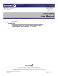
Figure 1:
Example of a
excom®-station
excom® is a remote I/O-system for PROFIBUS-DP for the use in explosion hazardous areas.
The system is equipped with bus-compatible, decentralized I/O-modules with protection class IP20 for
the connection of binary and analog intrinsically safe field devices. The Ex-protection type of the system
permits its use in Zones 1 and 2 (per EN 60079-10) and Zones 21 and 22 (per EN 61241-10).
The field current circuits are approved for the Zones 0, 1 and 20 and 21.
The system consists of power supply units or power supply modules, gateways, I/O-modules, as well as
module racks to accommodate all components. The connection of all modules is user-friendly:
Gateways, power supplies, and I/O-modules are plugged into the module rack. Thus all internal
connections are established; only the external voltage supply and the periphery must be connected.
The backplane is an integral part of the module racks. The backplane serves to distribute energy and to
transfer data. Module racks have two different sizes to accommodate a maximum of 16 modules and
2 gateways (MT16-…) or 24 modules and 2 gateways (MT24-…).
The module racks are available for a 24-VDC supply voltage and with the converter sub-rack MT-PPS
optionally for an AC-supply of 230/115 VAC. The connection level of the field current circuits is
equipped with removable screw terminals or cage clamp terminals.
The power supply units or power supply modules ensure that the entire system is supplied with
current. For the intended operation, one power supply unit or power supply module is sufficient.
In order to increase availability, an additional power supply unit or power supply module can be
connected (redundancy) when the module rack MT16-…/MT24 is used. When the converter sub-rack
MT-PPS with 230/115 VAC is used, an AC/DC-converter is also connected per power supply unit or
power supply module.
The gateways are masters for the internal data bus and slaves for the higher-level fieldbus and regulate
the entire data communication between an I/O-module and a process control system (PCS).
The gateway provides the expanded PROFIBUS-DP diagnosis, this means that diagnostic data,
including channel-specific error messages are made available to the user.
The data transmission to the PCS can be executed with suitable TURCK-couplers via fiber optic or
copper cables. In order to increase availability and failure safety, a second gateway is alloted
(redundancy) when the MT16-…/MT24-… is used.
18
D301266 0113 - excom®
Performance characteristics of the excom®-system
Note
It is possible to replace a redundant power supply unit or power supply module, as well as a
redundant gateway during operation!
When replacing a defective gateway, please note that the new device must have the same
firmware revision than the redundant gateway!
The I/O-modules are the interface to the periphery that is connected via the connection level of the field
current circuits. The digital modules, analog modules, and function modules permit the connection of
field devices with protection class Ex ia IIC. A total of up to 24 I/O-modules can be operated with the
module rack MT24… and 16 I/O-modules with the module rack MT16…
All I/O-modules can be hot-swapped (without power needing to be switched off); for example, to
replace defective modules. There is an automatic check whether the new module matches the
configuration. The existing data communication is not interrupted.
The modules are equipped with LEDs for "on-site" error analysis. Each I/O-module has LEDs for direct
diagnosis and status display of the I/Os. All displays meet NAMUR NE 44 or rather DIN EN 60073, which
means:
green = ready for operation
red = error
yellow = switch status of binary I/Os
The internal cycle time for a fully expanded system is below:
5 ms for MT16… (10 ms for MT24…) with purely binary processing
20 ms for MT16… (40 ms for MT24…) with analog signals
The response time also depends on the used PCS and the used fieldbus. The connection of HART®compatible field devices is supported. Continuous HART®-communication to the PCS is possible via the
PROFIBUS-DPV1.
A excom®-DTM (Device Type Manager) is used for configuration and parameterization in an
engineering tool. In stand-alone tools like PACTware™ the DTM is used for start-up and monitoring.
The DTM is based on the FDT-specification 1.2.
The parameterization of substitute values is supported by the excom®-system and generally occurs per
chanel. Depending on module type, the individually requested behavior of the periphery can be
adjusted for the purpose of the application.
D301266 0113 - excom®
19
Introduction of the excom®-system
2.2
Overview of the excom®-components
Note
The order information for all components of a excom®-system can be found in the catalog
"Remote I/O-excom®" (D300395).
Table 1:
Components of
the excom®system –
Module rack
Module rack for
Zone 1
Module rack for
Zone 2
MT16-2G
MT16-3G
– DC-supply 24 VDC
– max. 2 power supply
devices
– DC-supply 24 VDC
– max. 2 power supply
modules
Converter
sub-rack
MT24-3G
– DC-supply 24 VDC
– max. 2 power supply
modules
MT-PPS
– AC-supply
230/115 VAC
– max. 2 AC/DCconverters
– max. 2 gateways
– max. 2 gateways
– max. 2 gateways
– 16 I/O-modules
– 16 I/O-modules
– 24 I/O-modules
(max.)
(max.)
(max.)
– 128 binary I/Os (max.) – 128 binary I/Os (max.) – 192 binary I/Os (max.)
or 64 analog I/Os
or 64 analog I/Os
or 96 analog I/Os
(max.) or a
(max.) or a
(max.) or a
combination thereof
combination thereof
combination thereof
20
D301266 0113 - excom®
Overview of the excom®-components
Table 2:
Components of
the excom®system –
I/O-modules
I/O-modules
DM80Ex
8-channel binary I/O-module to connect NAMUR-sensors and small
performance actuators
DI40Ex
4-channel binary input-module to connect NAMUR-sensors, galvanically
isolated
DO401Ex
4-channel binary output-module to connect Ex i-magnet valves or
indicators < 0.75 W, galvanically isolated
AI401Ex
4-channel binary input-module to connect 2-wire transmitters,
galvanically isolated
AI41Ex
4-channel binary input-module to connect 4-wire transmitters,
galvanically isolated
AI43Ex
4-channel analog input-module to connect potentiometers with 3-wire or
4-wire technology
AO401Ex
4-channel analog output-module to connect analog actuators,
galvanically isolated
AIH40Ex
4-channel analog input-module to connect 2-wire transmitters with
HART®-functionality
AIH41Ex
4-channel analog input-module to connect 4-wire transmitters with
HART®-functionality
AOH40Ex
4-channel analog output-module to connect analog actuators with
HART®-functionality
TI40Ex
4-channel analog input-module to connect thermo couples (temperature
resistors and thermo elements)
TI41Ex
4-channel analog input-module to connect temperature resistor couples
(Pt100, Ni100 and Cu100)
DF20Ex
2-channel input-module to count impulses or to measure the frequency of
binary impulse sequences
D301266 0113 - excom®
21
Introduction of the excom®-system
Table 3:
Components of
the excom®system –
couplers
PROFIBUS-DP-coupler versions
SC12Ex
OC11Ex/2G.2 and OC11Ex/3G.2
– Coupling via copper cables
– Ex-separation between RS485 and RS485-IS
– Regeneration of amplitude and phase
– LWL-coupler
– Ex-separation between RS485 and RS485-IS
with the help of LWL-coupler
– Regeneration of amplitude and phase
– Transmission over long distances
uh
r
IS
an
de
rR
485-
(b)
RS
(a)
Sh
ie
ld
R
485-
485
Sh
ie
ld
RS
RS
Sh
ie
ld
1
PS VDC
24
IS
TU
0
1 =
2 =
au
3 =
4 = 19 9,60 to
5 = 45 ,2
6 = 93 ,4 0
Bau
7 = 18 ,7 5
= 50 7, 5
d
15 0, 50
00 00
3 4 5 rate
8
9 = n kB ,00
2
6
= ot it/s
not u
1
7
use sed
0 8
9
d
C
ülh
eim
SC
PTB 1
II 03 2E
(2
)G A x
U
D TEX
[E 21
I0 0 =
Ex
P = 3,
15
lin 0 = 12 71 V ib]
IIC
ea 12 9 m
r ch 0 A
m
ar W
U
ac
i
K
te Tu = 4,
D
rist = 2
-4
54
20 V
66 ic
...
M
+70
°C
01
02
2
PS VDC
24
22
D301266 0113 - excom®
3
excom®-system components
3.1
Overview of system architecture ......................................................................................................... 27
3.2
Module racks/module sub-racks of the excom®-system....................................................................... 28
General information ............................................................................................................................................................................... 28
Type code................................................................................................................................................................................................... 28
Module rack MT16-2G ........................................................................................................................................................................... 30
– Dimensional drawing of the module rack MT16-2G ............................................................................................................. 30
3.2.4 Module rack MT16-3G ........................................................................................................................................................................... 31
– Dimensional drawing of the module rack MT16-3G ............................................................................................................. 31
3.2.5 Module rack MT24-3G ........................................................................................................................................................................... 32
– Dimensional drawing of the module rack MT24-3G ............................................................................................................. 32
3.2.6 Converter sub-rack MT-PPS ................................................................................................................................................................. 33
– Dimensional drawing of the converter sub-rack MT-PPS .................................................................................................... 33
3.2.7 Technical data of the module racks/converter sub-racks......................................................................................................... 34
3.2.8 Mounting the module racks ................................................................................................................................................................ 35
3.2.9 Address switch on the module rack and addressing ................................................................................................................. 36
– PROFIBUS-DP-address switch ........................................................................................................................................................ 36
– Assignment of internal module address .................................................................................................................................... 36
– Access to the I/O-addresses ........................................................................................................................................................... 36
3.2.10 connection to PROFIBUS-DP on the module rack ....................................................................................................................... 37
3.2.1
3.2.2
3.2.3
3.3
Supply of the excom®-system ............................................................................................................... 38
3.3.1
3.3.2
3.3.3
3.3.4
3.3.8
General information ............................................................................................................................................................................... 38
Power supply units or power supply module – types................................................................................................................ 38
connection of the supply voltage via Ex e-connection terminals ......................................................................................... 39
Power supply unit PSD24Ex................................................................................................................................................................. 40
– Redundancy of PSD24Ex ................................................................................................................................................................. 40
– Mounting of the power supply units PSD24Ex to the backplane MT16-2G ................................................................. 41
– Technical data PSD24Ex ................................................................................................................................................................... 41
Power supply module PSM24-3G...................................................................................................................................................... 42
– Redundancy of PSM24-3G .............................................................................................................................................................. 42
– Technical data PSM24-3G ................................................................................................................................................................ 43
AC/DC-converter PPSA230Ex or rather PPSA115Ex.................................................................................................................... 44
– Redundancy of PPSA230Ex or rather PPSA115Ex ................................................................................................................... 44
– Technical data PPSA230Ex/PPSA115Ex ...................................................................................................................................... 45
Supply concepts ...................................................................................................................................................................................... 46
– 24-VDC supply – redundant ........................................................................................................................................................... 46
– 115/230-VAC-supply – optionally redundant .......................................................................................................................... 47
Use of the power supply unit cover BM-PS.................................................................................................................................... 48
3.4
Certified system enclosures ................................................................................................................. 49
3.4.1
3.4.2
3.4.3
General information ............................................................................................................................................................................... 49
Type code................................................................................................................................................................................................... 50
Mounting instructions for the system enclosures....................................................................................................................... 51
– Ambient conditions during the installation ............................................................................................................................. 51
– Completion of the temperatue test ............................................................................................................................................ 51
Technical data for the system enclosures ..................................................................................................................................... 52
Accessories for the system enclosures ............................................................................................................................................ 53
– Ventilation bolt ................................................................................................................................................................................... 53
– ELST-M20Ex (plastic design) ........................................................................................................................................................... 53
– ELVA-M20Ex (stainless steel) .......................................................................................................................................................... 53
Module rack accessories ....................................................................................................................................................................... 54
3.3.5
3.3.6
3.3.7
3.4.4
3.4.5
D301266 0113 - excom®
23
excom®-system components
– terminal block STB16-4RS/1.5-BU .................................................................................................................................................54
– Terminal block STB16-4RS/1.5-BU ................................................................................................................................................54
3.5
Gateway GDP-IS – head station............................................................................................................ 55
–
–
–
–
–
–
–
–
–
3.6
General information ..........................................................................................................................................................................55
Connection to higher-level systems ............................................................................................................................................55
Configuration via GSD-files .............................................................................................................................................................56
Gateway redundancy ........................................................................................................................................................................56
Function of the LEDs .........................................................................................................................................................................56
Special error scenarios with corresponding LED-displays ...................................................................................................57
Gateway diagnosis .............................................................................................................................................................................58
Parameters ............................................................................................................................................................................................59
Technical data ......................................................................................................................................................................................61
Gateway GDP-NI – head station ........................................................................................................... 62
–
–
–
–
–
–
–
–
–
General information ..........................................................................................................................................................................62
Connection to higher-level systems ............................................................................................................................................62
Configuration via GSD-files .............................................................................................................................................................63
Gateway redundancy ........................................................................................................................................................................63
Function of the LEDs .........................................................................................................................................................................63
Special error scenarios with corresponding LED-displays ...................................................................................................64
Gateway diagnosis .............................................................................................................................................................................65
Parameters ............................................................................................................................................................................................66
Technical data ......................................................................................................................................................................................68
3.7
Digital modules.................................................................................................................................... 69
3.7.1
DM80Ex - digital I/O-module, 8-channel.........................................................................................................................................69
– Configuration and data volume ....................................................................................................................................................69
– Connection figures .............................................................................................................................................................................71
– Parameters ............................................................................................................................................................................................72
– Channel-specific module diagnosis .............................................................................................................................................73
– Function of the LEDs .........................................................................................................................................................................73
– Technical data .....................................................................................................................................................................................74
DI40Ex - digital input module, 4-channel .......................................................................................................................................75
– Configuration and data volume ....................................................................................................................................................75
– Connection figures .............................................................................................................................................................................76
– Parameters ............................................................................................................................................................................................77
– Channel-specific modulediagnosis ..............................................................................................................................................77
– Function of the LEDs .........................................................................................................................................................................78
– Technical data ......................................................................................................................................................................................79
DO401Ex - digital output-module, 4-channel ...............................................................................................................................80
– Valve control .........................................................................................................................................................................................80
– Load curve .............................................................................................................................................................................................81
– Configuration and data volume ....................................................................................................................................................82
– Connection figures .............................................................................................................................................................................82
– Parameters ............................................................................................................................................................................................83
– Channel-specific modulediagnosis.............................................................................................................................................. 83
– Function of the LEDs .........................................................................................................................................................................84
– Technical data ......................................................................................................................................................................................85
3.7.2
3.7.3
3.8
Analog modules ................................................................................................................................... 86
3.8.1
AI401Ex - analog input module, 4-channel ....................................................................................................................................86
– Configuration and data volume ....................................................................................................................................................86
– Connection figures .............................................................................................................................................................................88
24
D301266 0113 - excom®
3.8.2
3.8.3
3.8.4
– Parameters ............................................................................................................................................................................................ 89
– Channel-specific module diagnosis ............................................................................................................................................ 90
– Function of the LEDs ......................................................................................................................................................................... 90
– Technical data ..................................................................................................................................................................................... 91
AI41Ex - analog input module, 4-channel ...................................................................................................................................... 92
– Configuration and data volume ................................................................................................................................................... 92
– Connection figures ............................................................................................................................................................................ 94
– Parameters ............................................................................................................................................................................................ 95
– Channel-specific module diagnosis ............................................................................................................................................ 96
– Function of the LEDs ......................................................................................................................................................................... 96
– Technical data ..................................................................................................................................................................................... 97
AI43Ex - analog input module, 4-channel ...................................................................................................................................... 98
– Configuration and data volume ................................................................................................................................................... 98
– Connection figures ..........................................................................................................................................................................100
– Parameters ..........................................................................................................................................................................................101
– Channel-specific module diagnosis ..........................................................................................................................................102
– Function of the LEDs .......................................................................................................................................................................102
– Technical data ...................................................................................................................................................................................103
AO401Ex – analog output module, 4-channel ...........................................................................................................................104
– Configuration and data volume .................................................................................................................................................104
– Connection figures ..........................................................................................................................................................................105
– Parameters ..........................................................................................................................................................................................106
– Channel-specific module diagnosis ..........................................................................................................................................107
– Function of the LEDs .......................................................................................................................................................................107
– Technical data ...................................................................................................................................................................................108
3.9
Analog HART® -compatible modules ................................................................................................. 109
3.9.1
AIH40Ex - analog input module, 4-channel.................................................................................................................................109
– Configuration and data volume .................................................................................................................................................109
– Error message via the status bit of the data telegram ........................................................................................................110
– Floating-point format of the HART®-variable .........................................................................................................................111
– Mapping of the input data ............................................................................................................................................................111
– Measurement range ........................................................................................................................................................................112
– Connection figures ..........................................................................................................................................................................112
– Parameters ..........................................................................................................................................................................................113
– Substitue value strategy ................................................................................................................................................................116
– Channel-specific module diagnosis ..........................................................................................................................................117
– Function of the LEDs .......................................................................................................................................................................118
– Technical data ...................................................................................................................................................................................119
AIH41Ex - analog input module, 4-channel.................................................................................................................................120
– Configuration and data volume .................................................................................................................................................120
– Error message via the status bit of the data telegram ........................................................................................................121
– Floating-point format of the HART®-variable .........................................................................................................................122
– Measurement ranges ......................................................................................................................................................................123
– Connection figures ..........................................................................................................................................................................123
– Parameters ..........................................................................................................................................................................................124
– Channel-specific module diagnosis ..........................................................................................................................................128
– Function of the LEDs .......................................................................................................................................................................129
– Technical data ...................................................................................................................................................................................130
AOH40Ex - analog output module, 4-channel............................................................................................................................131
– Configuration and data volume .................................................................................................................................................131
– Floating-point format of the -HART®-variables .....................................................................................................................132
– Measurement ranges ......................................................................................................................................................................133
– Connection figures ..........................................................................................................................................................................134
– Parameters ..........................................................................................................................................................................................135
3.9.2
3.9.3
D301266 0113 - excom®
25
excom®-system components
– Channel-specific module diagnosis .......................................................................................................................................... 138
– Function of the LEDs ...................................................................................................................................................................... 138
– Technical data ................................................................................................................................................................................... 139
3.10
Modules for temperature measuring.................................................................................................140
3.10.1 TI40Ex - temperature module, 4-channel .................................................................................................................................... 140
– Line compensation and cold-junction compensation ....................................................................................................... 140
– Configuration and data volume ................................................................................................................................................. 140
– Error message via status bit of the data telegram ............................................................................................................... 141
– Measurement range ....................................................................................................................................................................... 142
– Connection figures .......................................................................................................................................................................... 143
– Parameters ......................................................................................................................................................................................... 144
– Channel-specific module diagnosis .......................................................................................................................................... 147
– Function of the LEDs ...................................................................................................................................................................... 147
– Technical data ................................................................................................................................................................................... 148
3.10.2 TI41Ex - temperature module, 4-channel .................................................................................................................................... 149
– Configuration and data volume ................................................................................................................................................. 149
– Error message via status bit of the data telegram ............................................................................................................... 150
– Connection figures .......................................................................................................................................................................... 151
– Parameters ......................................................................................................................................................................................... 152
– Channel-specific module diagnosis .......................................................................................................................................... 153
– Function of the LEDs ...................................................................................................................................................................... 153
– Technical data ................................................................................................................................................................................... 154
3.11
Frequency / counter module ..............................................................................................................155
3.11.1 DF20Ex - frequency module or rather counter module.......................................................................................................... 155
– Count and frequency functionality ........................................................................................................................................... 155
– Count and frequency functionality ........................................................................................................................................... 155
– Connection diagram ....................................................................................................................................................................... 156
3.11.2 DF20Ex F - frequency module .......................................................................................................................................................... 157
– Measurement input ........................................................................................................................................................................ 157
– Input and determination of rotating direction ..................................................................................................................... 158
– Static evaluation ............................................................................................................................................................................... 158
– Dynamic evaluation ........................................................................................................................................................................ 158
– Function of the LEDs ...................................................................................................................................................................... 159
– Parameters ......................................................................................................................................................................................... 160
3.11.3 DF20Ex P - counter module .............................................................................................................................................................. 161
– Counter input .................................................................................................................................................................................... 161
– Input to determin count direction ............................................................................................................................................ 161
– Static evaluation ............................................................................................................................................................................... 161
– Dynamic evaluation ........................................................................................................................................................................ 162
– Function of the LEDs ...................................................................................................................................................................... 163
– Parameters ......................................................................................................................................................................................... 164
3.11.4 Substitute values and validity of measurement values for DF20Ex ................................................................................... 165
3.11.5 Channel-specific module diagnosis ............................................................................................................................................... 166
3.11.6 Technical data ........................................................................................................................................................................................ 167
3.12
Use of the blind module BM1 .............................................................................................................168
3.13
Module replacement (during operation) – coding pins .....................................................................169
3.13.1 Mechanical coding ............................................................................................................................................................................... 169
26
D301266 0113 - excom®
Overview of system architecture
3.1
Overview of system architecture
To accommodate all components, the system consists of power supply units or power supply modules,
gateways, I/O-modules, as well as module racks. The module rack has an integrated backplane.
The backplane distributes energy and transfers data and contains the connection layer for the field
devices.
The power supply units or power supply modules ensure that the entire system is supplied with
current.
For the correct operation, one power supply unit or power supply module is sufficient. In order to
increase availability, an additional power supply unit or power supply module can be connected
(redundancy) when the module rack MT16/MT24-… is used.
A
Figure 2:
Example
configuration of a
excom®-station
I
F
G
K
B
J
A
B
C
D
E
F
G
H
I
J
K
D
C
E
H
Power supply units (redundancy possible)
Ex e-connection for the external power supply under the cover
Selection of the network address via the rotary switch
Connections for PROFIBUS-DP RS485-IS
Connection layer for the intrinsically safe Ex i-field devices
Gateways
I/O-modules, different types
integrated guide for module insertion, slot coding
LEDs for status and I/Os
Module rack with backplane
Module front cover with mechanical coding
D301266 0113 - excom®
27
excom®-system components
3.2
Module racks/module sub-racks of the excom®-system
3.2.1
General information
excom®- components are mounted onto module racks. The excom®-module racks consist of a backplane
and the rack system that is mounted in front of it. The backplane distributes energy and transfers data
and contains the connection layer for the field devices.
The module rack is available in a combined protection class Ex e and Ex i and can be used in Zone 2.
The module supply on the backplane is limited in such a way that spark generation is prevented.
This is why I/O-modules and gateways can be hot-swapped (hot plug) when the excom® is used in
Zone 2. Here, data communication is not interrupted.
With the help of the AC/DC-converters on the converter sub-rack MT-PPS, the 230/115 VAC-supply
voltage is transformed to an unregulated 24-VDC-supply voltage and supplied to the power supply
units or power supply modules on the module rack. Here, an AC/DC-converter is connected per power
supply unit or power supply module. The converter sub-rack has a combined protection class Ex e and
Ex i and can be used in Zone 2.
3.2.2
Type code
Table 4:
Type code
module racks
Module rack
MT
16
–
2G
2G
Application in Zone 1
3G
Application in Zone 2
16
Slots for max. 2 gateways and 16 I/O-modules
24
Slots for max. 2 gateways and 24 I/O-modules
PPS
MT
Converter sub-rack for Zone 1
Module rack
Note
The current module rack version MT18-R024 has the same functions as the module rack
version MT16-2G and is therefore compatible.
28
D301266 0113 - excom®
Module racks/module sub-racks of the excom®-system
Three different module rack versions and one converter sub-rack are available.
Table 5:
Module rack
versions and
converter subracks
Module rack versions for Zone 2
MT16-3G
MT24-3G
– DC-supply 24 VDC
– max. 2 power supply modules
– DC-supply 24 VDC
– max. 2 power supply modules
– max. 2 gateways
– 16 I/O-modules (max.)
– 128 binary I/Os (max.) or 64 analog I/Os (max.)
or a combination thereof
– max. 2 gateways
– 24 I/O-modules (max.)
– 192 binary I/Os (max.) or 96 analog I/Os (max.)
or a combination thereof
Module rack versions for Zone 1
Converter sub-rack
MT16-2G
MT-PPS
– DC-supply 24 VDC
– max. 2 power supply units
– AC-supply 230/115 VAC
– max. 2 AC/DC-converters
– max. 2 gateways
– 16 I/O-modules (max.)
– 128 binary I/Os (max.) or 64 analog I/Os (max.)
or a combination thereof
D301266 0113 - excom®
29
excom®-system components
3.2.3
Module rack MT16-2G
The following figure shows the module rack MT16-2G that is equipped with MINI-COMBICON clamps
for the signal connection layer.
Figure 3:
Module rack
MT16-2G
G
A
H
I
B
A
B
C
D
E
F
G
H
I
C
E
D
F
Two slots for 24 VDC power supply units
Ex e-connection for the external power supply
Bridge for possible grounding of the shield of the data cable
Two 9-pole SUB-D-connectors for PROFIBUS RS485-IS
("Redundancy strategies for PROFIBUS-DP" page 225)
Rotary switch for setting the network address
("Address switch on the module rack and addressing" page 36)
Connection layer for the Ex i-field devices (MINI-COMBICON)
Slots for 2 gateways ("Redundancy strategies for PROFIBUS-DP" page 225)
Slots for max. 16 I/O-modules
Grounding bolt
Dimensional drawing of the module rack MT16-2G
Figure 4:
MT16-2G
440
413
132
260 235
ø7
30
D301266 0113 - excom®
Module racks/module sub-racks of the excom®-system
3.2.4
Module rack MT16-3G
The following diagram shows the module rack MT16-3G that is equipped with MINI-COMBICON clamps
for the signal connection layer.
Figure 5:
Module rack
MT16-3G
G
A
H
B
E
D
I
A
B
C
D
E
F
G
H
I
F
C
Two slots for 24-VDC power supply modules
Ex e-connection for the external power supply under the cover
Bridge for possible grounding of the shield of the data cable
Two 9-pole SUB-D-connectors for PROFIBUS RS485-IS
Rotary switch for setting the network address
("Address switch on the module rack and addressing" page 36)
Connection layer for the Ex i-field devices (MINI-COMBICON)
Slots for two gateways ("Redundancy strategies for PROFIBUS-DP" page 225)
Slots for max. 16 I/O-modules
Grounding bolt
Dimensional drawing of the module rack MT16-3G
Figure 6:
MT16-3G
380
352
130
260 235
ø7
D301266 0113 - excom®
31
excom®-system components
3.2.5
Module rack MT24-3G
The following figure shows the module rack MT24G-3G that is equipped with MINI-COMBICON clamps
for the signal connection layer.
Figure 7:
Module rack
MT24-3G
A
G
H
B
I
C
A
B
C
D
E
F
G
H
I
D
F
E
Two slots for 24-VDC power supply modules
Ex e-connection for the external power supply under the cover
Bridge for possible grounding of the shield of the data cable
Two 9-pole SUB-D-connectors for PROFIBUS RS485-IS
("Redundancy strategies for PROFIBUS-DP" page 225)
Rotary switch for setting the network address
("Address switch on the module rack and addressing" page 36)
Connection layer for the Ex i-field devices (MINI-COMBICON)
Slots for two gateways ("Redundancy strategies for PROFIBUS-DP" page 225)
Slots for max. 24 I/O-modules
Grounding bolt
Dimensional drawing of the module rack MT24-3G
Figure 8:
MT24-3G
525
498
130
260 235
ø7
32
D301266 0113 - excom®
Module racks/module sub-racks of the excom®-system
3.2.6
Converter sub-rack MT-PPS
The following figure shows the converter sub-rack MT-PPS.
Figure 9:
Converter sub-rack
MT-PPS
A
B
A Slots for 115/230 VAC converters
B Integrated filters
Dimensional drawing of the converter sub-rack MT-PPS
Figure 10:
MT-PPS
110
82
130
260 235
ø7
D301266 0113 - excom®
33
excom®-system components
3.2.7
Technical data of the module racks/converter sub-racks
Table 6:
Technical
data of the
module racks/
converter subracks
Type code
MT16-2G
MT16-3G
MT24-3G
MT-PPS
Connections
Bus (SUB-D-Miniature 9pole)
2
2
2
–
Power supply voltage
(Ex e double screw terminals)
–
–
–
6
Supply
(Ex e double screw terminals)
6
4
4
4
Connection cross-section
1…4 mm² inflexible or 1…2.5 mm² with wire end sleeve
Field devices
Connection cross-section
per module 4 × 4 terminals
–
0.25…1.5 mm² with wire end sleeve
(without plastic sleeve)
–
Slots
–/2
–/2
–/2
2/–
Gateway (max. expansion)
2
2
2
–
I/O-module (max.
expansion)
16
16
24
–
AC/DC-converter/DC power
supply module (power
supply unit)
Possible settings
Bus address
2 coded
Rotary switches
3 coded
rotary
switches
–
Values of the EC-type
examination certificate
Ex-approval
Marking
PTB 00 ATEX 2194 U
PTB 00 ATEX
2091 X
II 2 (1) G Ex eb ib [ia] IIC
II 2 G Ex e q II
T4
General information
Protection class
IP20
Ambient temperature
-20…+70 °C
≤ 95 % at 55 °C per EN 60068-2
Relative humidity
Vibration test and shock test
per IEC 60068-2-6 and IEC 60068-2-27
Dimensions
(without mounting angle)
B × H × T [mm]
34
440 × 260 ×
130
380 × 260 ×
130
525 × 260 ×
130
110 × 260 ×
130
D301266 0113 - excom®
Module racks/module sub-racks of the excom®-system
3.2.8
Mounting the module racks
The rack-system is made of extruded aluminum sheath. This guarantees increased stability and
shielding.
The module racks are suitable for wall-mount.
Danger
Possible injuries to persons because of incorrect use.
There are Ex e- and Ex i-circuits on the module rack. The module rack must only be
transported and stored in its original packaging.
Do not mount damaged devices or devices that are no longer in their original condition after
incorrect handling.
The module racks are mounted with M6-screws or M6-bolts.
#
Attention
Possible damage to enclosures caused by incorrect mounting.
For mounting in a stainless steel enclosure, special sliding nuts type GM306 and threaded
pins type GS406 are needed, together with M6-screw nuts per DIN 934.
D301266 0113 - excom®
35
excom®-system components
3.2.9
Address switch on the module rack and addressing
PROFIBUS-DP-address switch
In a PROFIBUS-DP-network a participant (here: excom®-station) is identified via a bus address.
Addresses 01 to 99 (99 participants) for MT16-3G or rather MT24-3G may be assigned.
Addresses 001 to 125 (125 participants) can be assigned for MT16-2G.
Bus addresses 00, 000, 126, and 127 must not be used.
Setting of the PROFIBUS-DP-address is done via rotary switches on the module rack. The switches
depict the digits of the network address.
For example, the following figure shows the setting of the network address "05® or rather "005".
MT16-2G
MT16-3G/MT24-3G
4 05 6
901
0
1
0
4 56
23
78
901
1st digit
23
4 56
23
901
901
4 56
78
901
78
23
78
4 56
10th digit
78
1st digit
23
4 56
10th digit
718
100th digit
213
0
1
Figure 11:
setting of network
address
"05" or rather "005"
901
Assignment of internal module address
The modules are slot-addressed. Thus individual modules do not require adjustments. Therefore, a
module in slot 0 automatically has the internal address 0, a module in slot 1 has the internal address 1,
etc.
Note
Slot 0 of module rack MT16/MT24… has a redundant design.
This slot is exclusive for the gateways.
Access to the I/O-addresses
Access to the I/O-periphery is controlled by the configuration of the system.
Access to respective channels depends on the higher-level system.
36
D301266 0113 - excom®
Module racks/module sub-racks of the excom®-system
3.2.10 connection to PROFIBUS-DP on the module rack
To connect the bus, two (with redundant design) 9-pole SUB D-female connectors are availabe. The
assignment meets the PROFIBUS-DP standard.
Figure 12:
SUB-D female
connector
5
4
9
Table 7:
Assignment of
the SUB-D pole
3
8
2
7
1
6
Pole No.
RS485-IS
1
n. c.
2
n. c.
3
RxD/TxD-P
4
n. c.
5
ISGND
Bus termination GND
6
ISP
Bus termination VP
7
n. c.
8
RxD/TxD-N
9
n. c.
D301266 0113 - excom®
Meaning
Received data/send data for B-cable (red)
Received data/send data for A-cable (green)
37
excom®-system components
3.3
Supply of the excom®-system
3.3.1
General information
The power supply is connected via Ex e-terminals on the module rack. Power supply units or power
supply modules that are plugged into designated slots on the module rack provide the voltage supply
specifically designed for the excom®-system and guarantee galvanic separation up to 60 V.
3.3.2
Power supply units or power supply module – types
One power supply unit or power supply module is sufficient for the correct operation of the excom®system. Redundant power supply units or power supply modules increase availability!
Note
In the planning phase, the respective nominal capacities of the modules must be added
together and compared to the nominal capacity of the power supply unit/power supply
module. Normally, the supplied load is sufficient for any combined I/O-module per station.
As an exception, this means if the load of the power supply unit/power supply module is not
sufficient, the possibility exists that the redundant power supply unit/power supply module
is used to supply the missing load. Carefully check whether the redundancy of the supply is
needed or not!
The type of the module rack/module sub-rack determines the possibilities for the supply of the station:
Table 8:
Module racks and
suitable power
supply units/
power supply
modules
38
Module rack
Module rack
MT16-2G
MT16-3G
MT24-3G
Converter
sub-rack
MT-PPS
Power supply unit PSD24Ex
with supply connection
19.5…32 VDC
Power supply unit PSM24-3G
with supply connection
19.5…32 VDC
AC/DC-converter PPSA230Ex
with supply connection
230-VAC supply voltage
or
PPSA115Ex with supply
connection
115-VAC supply voltage
The power supply units or
power supply modules are
downstream.
Redundancy possible!
Redundancy possible!
Redundancy possible!
2 power supply unit slots
2 power supply module slots
2 AC/DC-converter slots
D301266 0113 - excom®
Supply of the excom®-system
3.3.3
connection of the supply voltage via Ex e-connection terminals
To connect the supply voltage, Ex e-connection terminals are available on the module rack under a
IP30 cover.
Figure 13:
Cover plate over
voltage supply
Danger
Possible injuries to persons caused by electric shock.
No work must be done on the Ex e-connection terminals under voltage!
These connection terminals are positioned under a protective cover. Interference must only
occur when the respective supply voltage has been switched off.
When the power supply unit filter PS-F24-Ex is used, a waiting period of 5 min. must be
observed.
Note
The cover can only be opened when the power supply units or AC/DC-converters have been
pulled from the slots!
D301266 0113 - excom®
39
excom®-system components
3.3.4
Power supply unit PSD24Ex
Power supply unit for 24-VDC feed
Application in Zone 1 possible
,
Figure 14:
PSD24Ex
The power supply unit PSD24Ex supplies the excom®-system up to full expansion.
The power supply unit is designed for a combined protection class Ex m, Ex e, and Ex i and can be used
in Zone 1.
The power supply unit is fully potted and housed in an aluminum protective enclosure.
The PSD24Ex has a 19.5…32 VDC supply voltage.
The external supply is connected via Ex e-terminals on the module rack.
Redundancy of PSD24Ex
In combination with the module rack MT16-2G, two power supply units can be used.
When one device fails or when the supply line is interrupted, the other device supplies the entire
system.
Different potentials can be used for the supply.
Danger
Possible injuries to persons caused by electric shock.
No work must be done on the Ex e-terminals under voltage!
The terminals are mounted under a protective cover. Interference must only occur when the
respective supply voltage has been switched off.
Note
The power supply unit PSD24Ex can be hot-swapped.
By loosening at least one screw, the power supply unit is switched off.
For correct operation, all screws must be tightened.
40
D301266 0113 - excom®
Supply of the excom®-system
Mounting of the power supply units PSD24Ex to the backplane MT16-2G
The screws for mounting the power supply units PSD24Ex to the backplane MT16-2G must be screwed
tight so that the power supply units become operable. For correct mounting, please tighten the screws
as follows:
1. top left
2. bottom right
3. top right
4. bottom left
Figure 15:
Order in which to
tighten the screws
1
3
4
2
Technical data PSD24Ex
Table 9:
Technical data
PSD24Ex
Type code
PSD24Ex
Supply voltage
external
19.5…32 V DC (ripple Wpp ± 10 %)
Power consumption
≤ 66.5 W
Power output
≤ 60 W
Ex-approval
PTB 00 ATEX 2193
Marking of device
II 2 G Ex eb ib [ia] IIC
Rated voltage Um
60 V
LED displays
Operating readiness
1 × green
Supply
1 × green
General information
Galvanic isolation
on all sides
Protection class
IP50
Ambient temperature
-20…+70 °C
Relative humidity
≤ 95 % at 55 °C per EN 60068-2
Vibration test and shock test
per IEC 60068-2-6 and IEC 60068-2-27
Mounting
Flange, 4 × M4-screws
Dimensions B × H × T [mm]
45 × 155 × 106
D301266 0113 - excom®
41
excom®-system components
3.3.5
Power supply module PSM24-3G
Power supply module for 24-VDC feed
Application in Zone 2 possible
Figure 16:
PSM24-3G
The power supply module PSM24-3G supplies the excom®-system up to full expansion.
The power supply module has a module design and can be used in Zone 2.
The PSM24-3G has a supply voltage of 19.5…32 VDC.
The external supply is connected via Ex-e terminals on the module rack.
Danger
Possible injuries to persons caused by electric shock.
No work must be done on the Ex e-terminals under voltage!
The terminals are mounted under a protective cover. Interference must only occur when the
respective supply voltage has been switched off.
Redundancy of PSM24-3G
Two power supply modules can be used in combination with a suitable module rack. When one device
fails or when the supply line is interrupted, the other device supplies the entire system.
Different potentials can be used for the supply.
42
D301266 0113 - excom®
Supply of the excom®-system
Technical data PSM24-3G
Table 10:
Technical data
PSM24-3G
Type code
PSM24-3G
Supply voltage
external
19.5…32 V DC (ripple Wpp ± 10 %)
Power consumption
≤ 66.5 W
Power output
≤ 60 W
Rated voltage
40 V
Ex-approval
PTB 12 ATEX 2009
Marking
II 3 (2) G Ex nAc ic [ib] IIC T4
LED displays
Operating readiness
1 × green
Error message
1 × red
General information
Galvanic isolation
safe between input- and output-circuit
Protection class
IP20
Ambient temperature
-20…+70 °C
Relative humidity
≤ 95 % at 55 °C per EN 60068-2
Vibration test and shock test
per IEC 60068-2-6 and IEC 60068-2-27
Mounting
Module design, pluggable into module rack
Dimensions B × H × T [mm]
18 × 118 × 103
D301266 0113 - excom®
43
excom®-system components
3.3.6
AC/DC-converter PPSA230Ex or rather PPSA115Ex
For 230/115-VAC feed
AC/DC-conversion of supply voltage into an unregulated direct voltage (24 VDC)
Use on module rack MT-PPS
Only usable with downstream power supply unit or downstream power supply module.
Application in Zone 1 possible
Figure 17:
PPSA230Ex and
PPSA115Ex
The AC/DC-converter PPSA230Ex or rather the PPSA115Ex supplies the excom®-system up to full
expansion. The converter has a combined protection class Ex m and Ex e and can be used in Zone 1.
The converter is fully potted and housed in an aluminum protective enclosure.
The PPSA230Ex has a supply voltage of 230 VAC and the PPSA115Ex has a supply voltage of 115 VAC.
The external supply is connected via Ex e-terminals on the module rack.
Redundancy of PPSA230Ex or rather PPSA115Ex
Two converters can be used in combination with the module rack MT-PPS.
When one device fails or when the supply line is interrupted, the other device supplies the entire
system.
Different potentials can be used for the supply.
Danger
Possible injuries to persons caused by electric shock.
No work must be done on the Ex e-terminals under voltage!
The terminals are mounted under a protective cover. Interference must only occur when the
respective supply voltage has been switched off.
The converters must not be replaced under voltage.
44
D301266 0113 - excom®
Supply of the excom®-system
Technical data PPSA230Ex/PPSA115Ex
Table 11:
Technical data
PPSA230Ex /
PPSA115Ex
Type code
Input voltage
Input power
Output power
PPSA230Ex
PPSA115Ex
200…250 VAC
100…125 VAC
≤ 75 VA
≤ 66.5 W
Ex-approval
PTB 04 ATEX 2047
Marking
II 2 G Ex e m IIC T4
Rated voltage Um
250 V
General information
Protection class
Ambient temperature
Relative humidity
Vibration test and shock test
Mounting
Dimensions B × H × T [mm]
D301266 0113 - excom®
IP50
-20…+70 °C
≤ 95 % at 55 °C per EN 60068-2
per IEC 60068-2-6 and IEC 60068-2-27
Flange, 4 × M4-screws (Torx)
45 × 155 × 106
45
excom®-system components
3.3.7
Supply concepts
24-VDC supply – redundant
The following components are needed:
"Module rack MT16-2G" with
2 × "Power supply unit PSD24Ex"
Figure 18:
Connection to the
module rack
MT16-2G:
Redundant supply
PSD24Ex
24 VDC
24 VDC
PSD24Ex
+
–
PE
+
–
PE
The following components are needed:
"Module rack MT16-3G" or "Module rack MT24-3G" with
2 × "Power supply module PSM24-3G"
Figure 19:
Connection to the
module rack
MT16-3G or rather
MT24-3G:
Redundant supply
PSM24
24 VDC
24 VDC
46
+
–
+
–
D301266 0113 - excom®
Supply of the excom®-system
115/230-VAC-supply – optionally redundant
The following examples show circuits on the converter sub-rack MT-PPS. The two AC/DC-converters
are connected parallel to one or two separate voltage sources. The following components are needed:
"Converter sub-rack MT-PPS" with 1 × "AC/DC-converter PPSA230Ex or rather PPSA115Ex" and
"Module rack MT16-2G" with 1 × "Power supply unit PSD24Ex" or
"Module rack MT16-3G" or "Module rack MT24-3G" with 1 × "Power supply module PSM24-3G"
Figure 20:
Connection on the
sub-rack MT-PPS redundant supply
PPSA
VAC
VAC
L
N
PE
L
N
PE
PPSA
+
–
+
–
Note
For internal voltage stabilization, the power supply unit filter, PS-F24Ex, is mounted onto the
terminals of the 24-VDC supply.
D301266 0113 - excom®
47
excom®-system components
3.3.8
Use of the power supply unit cover BM-PS
For the unpopulated power supply unit or AC/DC-converter slot, the power supply unit cover BM-PS
is available.
Figure 21:
Power supply unit
cover BM-PS
Attention
Possible damage to device caused by intruding foreign objects.
Empty slots for power supply units or AC/DC-converters must be covered with an IP20-cover.
48
D301266 0113 - excom®
Certified system enclosures
3.4
Certified system enclosures
3.4.1
General information
The certified system enclosures consist of a stainless steel enclosure with ignition protection type
Increased Safety "e" with integrated module rack sizes MT16 or MT24.
The module rack can be populated with different modules. In addition, one or two filters are built in.
The system enclosures already have system approval and this is why the user is not required to approve
individual components of the assembly.
All components are tested and certified according to separate verification certificates.
The installation or rather assembly is done in the factory to meet the required distances, as well as air
and creep distances. The TURCK-Ex stainless steel enclosures are used in the Ex-area, (Zone 1) approved
and also suitable for harsh and aggressive environments.
The system enclosures are designed in such a way that a maximum population with power supply unit
or power supply module and I/O-modules is possible.
Figure 22:
Example for a
system enclosure
D301266 0113 - excom®
49
excom®-system components
3.4.2
Type code
The available certified systems can be ordered with the help of the following type code:
Table 12:
Type code
system
enclosures
System enclosures
EG–VA
655526/
1
1–
02
0
0/
…
Meaning
Special No. for accessory
equipment like trace
heating systems, circuit
breakers, fuses, or
lightning protection
components
0
1
0
no installation of
segment coupler OC11
1
Installation of segment
coupler OC11
2
Installation of two
segment couplers OC11
0
without converter subrack MT-PPS
1
with converter sub-rack
MT-PPS
00
no module rack
01
reserved
02
Module rack MT16-2G
03
reserved
04
reserved
05
Module rack MT16-3G
06
Module rack MT24-3G
07
reserved
08
reserved
09
Module rack MT24-N
0
dummy plate
1
Flange plate M16
2
Flange plate M20
X
Special design via SENo.
0
no window
1
Window
Material 1.4301
Material 1.4404
WW here 65
Enclosure width in cm
HH here 55
Enclosure height in cm
DD here 26
EG–VA
50
1
Enclosure depth in cm
excom®-enclosure,
Stainless steel design
D301266 0113 - excom®
Certified system enclosures
3.4.3
Mounting instructions for the system enclosures
The system enclosures have a perforated flange plate/hole pattern.
For the holes, ATEX-approved Ex e-cable screws and ventilation bolts are used. The operator must
ensure that during cable installation at least protection class IP54 is followed.
The following installation instructions for the TURCK stainless steel field enclosures must be adhered to:
The enclosures must be installed in such a way that the screws are at the bottom.
The window on the enclosure must not be damaged to ensure correct operation.
Ambient conditions during the installation
The permitted ambient temperature range of the excom®-modules and components can be found in
the individual certificates. After installation into a field enclosure, it must be ensured that the permitted
ambient temperature of the used modules or rather components is not higher than the ambient
temperature of the field device during operation. The enclosure must have adequate ventilation.
Here, it is important to take into consideration the internal power loss inside the field enclosure.
Note
The power loss that is shown by the characteristic curves (figures 23 and 24) results from the
fact that the nominal values (internal power consumption) of the individual modules are
added. Here, the additional power loss of the power supply unit(s) or power supply
module(s) has been taken into consideration. External thermal sources like solar radiation, for
example, have not been taken into consideration. If additional components are installed into
the housing next to the excom®-system, their power must also be taken into consideration
and certified with an individual approval.
Completion of the temperatue test
Attention
Possible damage to device caused by excessive ambient temperature.
Please take into consideration that additional modules in a excom®-system cause an increase
of total power, which leads to a decrease of the permittable ambient temperature.
Please take measures to reduce the ambient temperature. Please avoid direct solar radiation!
With direct solar radiation, the ambient temperature must be reduced even more.
D301266 0113 - excom®
51
excom®-system components
Temperature characteristic curve for enclosures EG-VA655521…
Tu[°C]
Figure 23:
Temperature
60
Characteristic curve
55
EG-VA655521/…
50
45
40
35
30
15
20
25
30
35
40
45
50
55
60
Pv[W]
Temperature characteristic curve for the enclosure EG-VA405521…
Tu[°C]
Figure 24:
Temperature
60
Characteristic curve
55
EG-VA405521/…
50
45
40
35
30
15 17,5 20 22,5 25 27,5 30 32,5 35
Pv[W]
Technical data for the system enclosures
Table 13:
Stainless steel
System enclosure
Type code
Ident-No.
Ex-approval per conformity
declaration
Marking
upon request
PTB 03 ATEX 1028
II 2 G Ex e d mb q ib [ia] [ib op is] IIC T4
Enclosure material
Stainless steel 1.4404/AISI 316L
Material strength
1.5 mm
Surface
polished (240th grain size)
Sealing material
Acrylic, silicone, rubber
Revision opening
ESG-saftey glass with seal
Protection class (IEC/EN 60529)
Shock resistance (EN 50014)
IP54
> 7 joule
Vibration test
per IEC 60068-2-6
Shock test
per IEC 60068-2-27
Ambient temperature
Flange connection plate/hole
pattern
52
EG-VA…
-20…+70 °C
Stainless steel 2.0 mm with drilling holes and factorymounted cable glands
D301266 0113 - excom®
Certified system enclosures
3.4.4
Accessories for the system enclosures
Ventilation bolt
Especially inside enclosures that are installed in the field there will be condensation because of existing
temperature differences (inside/outside). This may negatively impact functionality (corrosion, short
circuits).
The ventilation bolts allow good ventilation and therefore help prevent condensation. In addition and
in extreme cases, the condensation water collected at the bottom of the housing may drain off.
A labyrinth-design ensures that water cannot penetrate while ventilation takes place.
ELST-M20Ex (plastic design)
Figure 25:
Ventilation bolt
ELST-M20Ex
ELVA-M20Ex (stainless steel)
Figure 26:
Ventilation bolt
ELVA-M20Ex
Attention
Possible damage to device when the ventilation bolt is not used.
The ventilation bolt ELVA-M20Ex must be used in areas with dust. It meets the requirements
of protection class IP65 and above.
D301266 0113 - excom®
53
excom®-system components
3.4.5
Module rack accessories
To connect the field devices to the signal connection layer of the excom®-system, MINI-COMBICONterminals are used, which can be populated either with terminal blocks that can be mounted with
screws or that have cage clamp technolgy.
terminal block STB16-4RS/1.5-BU
set with 16 pieces 4-pole terminal block, screw terminals blue
Figure 27:
Terminal block
STB16-4RS/1.-BU
Terminal block STB16-4RS/1.5-BU
Set with 16 pieces 4-pole terminal block, cage clamp terminals blue
Figure 28:
Terminal block
STB16-4RC/1.5-BU
54
D301266 0113 - excom®
Gateway GDP-IS – head station
3.5
Gateway GDP-IS – head station
Figure 29:
Gateway GDP-IS
General information
The excom®-gateway GDP-IS is an intrinsically safe gateway for PROFIBUS-DPV1.
It connects the excom®-stations to the higer-level PROFIBUS fieldbus system and controls the entire
data communication. In addition, the gateway provides the entire diagnosis, including channel-specific
diagnosis. Manufacturer-specific error codes are also generated. This includes, for example, HART®communication errors, power supply unit errors or power supply module errors, planning errors, as well
as information via simulation, internal communication, redundancy switching, etc.
Note
When excom®-gateways are used in existing installations with redundant bus coupling, it
must be ensured that both gateways have the same hardware and firmware.
Connection to higher-level systems
For PROFIBUS-DP connection either fiber optic or copper cables can be used. When using fiber optic
cables, select a respective converter from fiber optic cable to RS485-IS. The coupler-system "Segment
coupler OC11Ex/…" page 182 converts the RS485-IS signals to intrinsically safe fiber optic cable signals.
With copper cables use a respective segment coupler (RS 485-IS coupler), for example, "Segment
coupler SC12Ex" page 175 to guarantee Ex-protection.
The gateway can be operated with a max. transmission speed of up to 1500 kBaud. The module rack
has a standard SUB-D connector for bus connection.
excom® can be connected with the interface to the PROFIBUS-DP per IEC 61158 to each host-system
that contains a PROFIBUS-DP-master Class 1.
With the help of the PROFIBUS-DP-standards it is guaranteed that the configuration, the
parameterization, the diagnostic messages, as well as the cyclic data exchange are processed between
Master and excom®. For processing the acyclic services on the PROFIBUS-DP, the DPV1-expansions in
excom® are implemented.
With the help of GSD-files all required behaviors for excom® are defined on the PROFIBUS-DP. In
addition, the configurations and parameters of the individual modules are stored here. For the
configuration of excom®, the GSD-files must be made part of the respective hardware configurator of
the host-system. This guarantees that the PROFIBUS-DP-master is supplied with information and data
sets valid for excom® when configuration takes place.
D301266 0113 - excom®
55
excom®-system components
Configuration via GSD-files
The gateway GDP-IS also has GSD-files. They are available in German and English "Use of GSD-files"
page 245.
The difference between GSD-file versions 1.6 x and 2.0 x involves the use or rather the support of DPV1specific functions and key words, e.g., those that are used with PNO-redundancy implementation.
Gateway redundancy
When two gateways and two bus cables are used, uninterruptable communication is guaranteed even
when one gateway and one bus cable fail. If a gateway fails, a bumpless switch to the second gateway
takes place; this corresponds to line redundancy. The system redundancy (two Masters connected to
one gateway via their own segment couplers) is also supported.
Note
By using suitable host-systems, the configuration can be changed during operation.
Function of the LEDs
With the help of the 5 front-side LEDs, status (operating mode), internal or rather external
communication, redundancy status, and system configuration are displayed.
Here is an overview of the LED functions.
Table 14:
LED
Functions
LED
Behavior
Function
Status
green
Ready for operation
off
Not ready for operation (no supply)
yellow
Internal communication ok
red
No communication via the backplane bus
blinking
yellow
Invalid PROFIBUS-DP-address (000)
red
No data exchange with PROFIBUS-DP-master
yellow
Data exchange with PROFIBUS-DP-master
PRIO
(redundancy status)
off
Gateway is passive
yellow
Gateway is active
Config
off
Configuration ok
blinking red
Configuration error (missing or wrongly plugged
modules)
CAN
PDP
56
D301266 0113 - excom®
Gateway GDP-IS – head station
Special error scenarios with corresponding LED-displays
Table 15:
PROFIBUS-Error
Table 16:
No internal
communication
Table 17:
Configuration
error
LED
Behavior
Possible source of error
status
green
CAN
yellow
PDP
red
– no communication with PROFIBUS
– excom®-address wrong
– double assignment to PROFIBUS-participants
– no bus termination
– defective cabling
PRIO
(redundancy status)
yellow
Config
off
LED
Behavior
Possible source of error
status
green
CAN
red
PDP
yellow
– no internal communication
– no modules plugged
– module does not interfere with the internal
communication bus
PRIO
(redundancy status)
yellow
Config
blinking red
LED
Behavior
Possible source of error
status
green
CAN
yellow
PDP
yellow
– no modules plugged
– module in wrong position
– modules are not correctly plugged into the rack
– modules are not parameterized
PRIO
(redundancy status)
yellow
Config
blinking red
D301266 0113 - excom®
57
excom®-system components
Gateway diagnosis
The gateway also provides manufacturer-specific error codes next to standard diagnoses. For example,
these are power supply unit errors or power supply module errors, project planning mistakes, internal
communication, redundancy switches, etc.
Table 18:
Special error
codes of the
gateway
diagnosis
58
Error code No.
Meaning
16
ROM-error
17
RAM-error
18
EEPROM-error
19
Starting up after a cold start
20
Different configuration (with redundancy)
21
Different firmware (with redundancy)
22
Error function of the internal bus (CAN-error)
23
Error function of the internal bus (passive) (CAN-error)
24
Error in power supply unit or power supply module 1
25
Error in power supply unit or power supply module 2
26
Starting up after Watchdog-Reset
27
Redundancy switch has taken place
28
Redundant gateway is missing
29
Redundant gateway is not ready
30
Redundant gateway has an error
31
Redundant gateway has no PROFIBUS-DP communication
D301266 0113 - excom®
Gateway GDP-IS – head station
Parameters
Table 19:
Parameters
gateway
Parameter name
Value
Meaning
power frequency
50 Hz
60 Hz
50 Hz or 60 Hz filter to suppress power-supplycaused, superimposed interferences in signal
cables.
Analog data format
Status MSB
Status LSB
no status
The status bit of an analog input channel can be
mapped into the process input data of the
channel and the position (MSB or LSB) can be
determined.
Status MSB:
Status bit at bit position 215
Status LSB:
Status bit at 20
no status
measurement value without status bit
module rack
MT8
MT16
MT24
MT8 (8 I/O-modules)
MT16 (16 I/O-modules)
MT24 (24 I/O-modules)
redundancy mode
off
line redundancy
system redundancy
selection of redundancy type:
off:
gateway without redundancy function
line redundancy:
flying redundancy system redundancy:
system redundancy -
power supply module
simple
redundant
With redundant supply via two power supply
units PSD24Ex or power supply modules PSM243G , the power supply module diagnosis is
activated with the "redundant" setting.
HCIR active
off
on
Activation of online-configuration
Note: This bit must be set with the master before
the HCIR-sequence starts.
HCIR WCBC factor
Basis × 1
Basis × 10
Factor for generating the max. switching time
between old and new configuration. The
configuration can be changed by module
replacement (hot swapping) and configuration
expansion (configuration in Run) during
operation. During the switching time, the
outputs are "held" at the current value.
HCIR WCBC Basis
(× 100 ms)
0…63
(Default: 5)
Determines the basis for the switching time.
When the PROFIBUS-master supports HCIR, this
parameter is set automatically.
Address Offset
off
on
Activation of the Address Offset with line
redundancy
D301266 0113 - excom®
59
excom®-system components
Table 19: (cont.)
Parameters
gateway
Parameter name
Value
Meaning
Offset value
0…124
(Default: 0)
Address Offset to generate a virtual address for
the redundant gateway.
(Standard value: 0)
CAN-redundancy
off
on
Redundancy of the internal communication
between gateway and I/Os
SF2/ SF3
reserved
The following parameter exclusively refers to the gateway configuration with the add-on
"C" (cyclic data) or "YO" (control data for the Yokogawa-redundancy) to the product name.
cyclic data
The default value of this parameter is "0" and
must not be changed.
Depending on the configuration in the network-configurator of the control software, the gateway
(GDP-IS) can be equipped with an additional function. These additional functions are identified by
adding "C" (cyclic data) or "YO" (control data for Yokogawa-redundancy) to the product name (refer to
"Configuration of the gateway" page 247).
C:
In this configuration the gateway provides an input word and an output word.
The input data word and the output data word are used as status- and control-register of the gateway.
These status descriptions are used to indicate, for example, which of the two gateways is "active" and
which is "passive" when the redundancy is switched. If a gateway fails, this status information can be
collected and as a measure, the adjacent gateway can be activated with the help of the output data
word.
YO:
Settings that are needed for the Yokogawa-redundancy are being activated. More details can be found
in the application report "excom®-integration in CentumVP/CS3000."
60
D301266 0113 - excom®
Gateway GDP-IS – head station
Technical data
Table 20:
Technical data
GDP-IS
Type code
GDP-IS/FW2.x
Supply voltage
via the module rack, central power supply unit or power
supply module
Power consumption
≤ 1W
Galvanic isolation
galvanic isolation per EN 60079-11 on all sides
Ex-approval per conformity
declaration
PTB 09 ATEX 2013
Marking
É II 2 G Ex ib IIC T4
Max. values (RS485-IS fieldbus
connection)
– Max. output voltage Uo
≤ 3.6 V
– Max. output current Io
≤ 125 mA
– Max. output power Po
≤ 112.5 mW
Characteristic curve
linear
Max. input voltage Uo
≤ 4.2 V
Displays
Operating readiness
1 × green/red
Int. communication (CAN)
1 × yellow/red
Ext. communication (PDP)
1 × yellow/red
Redundancy readiness (PRIO)
1 × yellow/red
Error message
1 × red
Protection class
IP20
General information
Ambient temperature
-20 …+ 70 °C
Relative humidity
≤ 93 % at 40 °C per IEC 60068-2-3 Test Ca
Vibration test
per IEC 60068-2-6
Shock test
per IEC 60068-2-27
External RS 485-fieldbus system
Ignition protection class
Ex ib IIC
Max. values of each terminal pair
Ui
4.2 V
Max. values of the sum of the terminal pairs
Ii
4.8 A
Cables: cable type A or rather B (per EN 60079-25 )
L’/R’:
≤ 15 μH/Ω (loop resistance)
C’
≤ 250 nF/km
Flexible wire diameter
≥ 0.2 mm
concentrated inductances and capacities in the fieldbus
system path are not permitted.
D301266 0113 - excom®
61
excom®-system components
3.6
Gateway GDP-NI – head station
Figure 30:
gateway GDP-NI
General information
The excom®-gateway GDP-NI is a gateway for PROFIBUS with RS485 standard interface. Use only when
mounted in non-ex areas (N = Non-Ex). The separation point to the intrinsically safe part of the system
is integrated in the gateway (I = isolated). The segment coupler is not needed.
The gateway controls the connection of the excom®-stations to the higher-level PROFIBUS fieldbus
system, as well as the entire data communication. In addition, the gateway provides the entire
diagnosis, including channel-specific diagnosis. Manufacturer-specific error codes are also generated.
This includes, for example, HART®-communication errors, power supply module failures, planning
errors, as well as information via simulation, internal communication, redundancy switches, etc.
Note
When excom®-gateways are used in existing installations with redundant bus coupling, it
must be ensured that both gateways have the same hardware and firmware.
Connection to higher-level systems
For PROFIBUS-DP connection either fiber optic or copper cables can be used. When using fiber optic
cables, select a suitable converter for fiber optic cable to RS485. The coupler-system "Segment coupler
OC11Ex/…" page 182 converts the RS485-signals to fiber optic cable signals.
The gateway can be operated with a max. transmission speed of up to 1500 kBaud. The module rack
has a standard SUB-D connector for bus connection.
excom® can be connected and operated with the interface to the PROFIBUS-DP per IEC 61158 to each
host-system that contains a PROFIBUS-DPmaster Class 1.
The PROFIBUS-DP-standards ensure that the configuration, the parameterization, the diagnostic
messages, as well as the cyclic data exchange between master and excom® are processed.
For processing the acyclic services on the PROFIBUS-DP, the DPV1-expansions in excom® are
implemented.
With the help of GSD-files all required behaviors for excom® are defined on the PROFIBUS-DP.
In addition, the configurations and parameters of the individual modules are stored here. For the
configuration of excom®, the GSD-files must be made part of the respective hardware configurator of
the host-system. This guarantees that the PROFIBUS-DP-master is supplied with information and data
sets valid for excom® when configuration takes place.
62
D301266 0113 - excom®
Gateway GDP-NI – head station
Configuration via GSD-files
The gateway GDP-NI also has GSD-files. They are available in German and English "Use of GSD-files"
page 245.
The difference between both GSD-file versions involves the use or rather support of DPV1-specific
functions and key words, for example, in connection with the implementation of PNO-redundancy.
Gateway redundancy
When two gateways and two bus cables are used, uninterruptable communication is guaranteed even
when one gateway and one bus cable fail. If a gateway fails, a bumpless switch to the second gateway
takes place; this corresponds to line redundancy. The system redundancy (two Masters connected to
one gateway via their own segment couplers) is also supported.
Note
By using suitable host-systems, the configuration can be changed during operation.
Function of the LEDs
With the help of the 5 front-side LEDs, status (operating mode), internal or rather external
communication, redundancy status, and system configuration are displayed.
Here is an overview of the LED functions.
Table 21:
LED
Functions
LED
behavior
function
Status
green
Ready for operation
off
Not ready for operation (no supply)
yellow
Internal communication ok
red
No communication via the backplane bus
blinking
yellow
Invalid PROFIBUS-DP-address (000)
red
No data exchange with PROFIBUS-DP-master
yellow
Data exchange with PROFIBUS-DP-master
PRIO
(redundancy status)
off
Gateway is passive
yellow
Gateway is active
Config
off
Configuration ok
blinking red
Configuration error (missing or wrongly plugged
modules)
CAN
PDP
D301266 0113 - excom®
63
excom®-system components
Special error scenarios with corresponding LED-displays
Table 22:
PROFIBUS-Error
Table 23:
No internal
communication
Table 24:
Configuration
error
64
LED
Behavior
Possible source of error
Status
green
CAN
yellow
PDP
red
– no communication with PROFIBUS
– excom®-address wrong
– double assignment to PROFIBUS-participants
– no bus termination
– defective cabling
PRIO
(redundancy status)
yellow
Config
off
LED
Behavior
Possible source of error
Status
green
CAN
red
PDP
yellow
– no internal communication
– no modules plugged
– Module does not interfere with the internal
communication bus
PRIO
(redundancy status)
yellow
Config
blinking red
LED
Behavior
Possible source of error
Status
green
CAN
yellow
PDP
yellow
– no modules plugged
– module in wrong position
– modules are not correctly plugged into the rack
– modules are not parameterized
PRIO
(redundancy status)
yellow
Config
blinking red
D301266 0113 - excom®
Gateway GDP-NI – head station
Gateway diagnosis
The gateway also provides manufacturer-specific error codes next to standard diagnoses. For example,
these are power supply module errors, planning errors, internal communication, redundancy switches,
etc.
Table 25:
Special error
codes of the
gateway
diagnosis
Error code No.
Meaning
16
ROM-error
17
RAM-error
18
EEPROM-error
19
Starting up after a cold start
20
Different configuration (with redundancy)
21
Different firmware (with redundancy)
22
Error function of the internal bus (CAN-error)
23
Error function of the internal bus (passive) (CAN-error)
24
Error in the power supply module 1
25
Error in the power supply module 2
26
Starting up after Watchdog-Reset
27
Redundancy switch has taken place
28
Redundant gateway is missing
29
Redundant gateway is not ready
30
Redundant gateway has an error
31
Redundant gateway has no PROFIBUS-DP communication
D301266 0113 - excom®
65
excom®-system components
Parameters
Table 26:
Parameters
Gateway
66
Parameter name
Value
Meaning
Power frequency
50 Hz
60 Hz
50 Hz or 60 Hz filter to suppress power-supplycaused, superimposed interferences in signal
cables.
Analog data format
Status MSB
Status LSB
No status
The status bit of an analog input channel can be
mapped into the process input data of the
channel and the position (MSB or LSB) can be
determined.
Status MSB:
Status bit at bit position 215
Status LSB:
Status bit at 20
No status
Measurement value without status bit
Module rack
MT8
MT16
MT24
MT8 (8 I/O-modules)
MT16 (16 I/O-modules)
MT24 (24 I/O-modules)
Redundancy mode
off
Line redundancy
System redundancy
Selection of redundancy type:
off:
Gateway without redundancy function
Line redundancy:
Flying redundancy System redundancy:
System redundancy -
Power supply module
simple
redundant
With redundant supply via two power supply
units PSD24Ex or power supply modules PSM243G , the power supply module diagnosis is
activated with the "redundant" setting.
HCIR active
off
on
Activation of online-configuration
Note: This bit must be set with the master before
the HCIR-sequence starts.
HCIR WCBC factor
Basis × 1
Basis × 10
Factor for generating the max. switching time
between old and new configuration. The
configuration can be changed by module
replacement (hot swapping) and configuration
expansion (configuration in Run) during
operation. During the switching time, the
outputs are "held" at the current value.
HCIR WCBC Basis
(× 100 ms)
0…63
(Default: 5)
Determines the basis for the switching time.
When the PROFIBUS-master supports HCIR, this
parameter is set automatically.
Address Offset
off
on
Activation of the Address Offset with curve
redundancy
D301266 0113 - excom®
Gateway GDP-NI – head station
Table 26: (cont.)
Parameters
Gateway
Parameter name
Value
Meaning
Offset value
0…124
(Default: 0)
Address Offset to generate a virtual address for
the redundant gateway.
(Standard value: 0)
CAN-redundancy
off
on
Redundancy of the internal communication
between gateway and I/Os
SF2/ SF3
reserved
The following parameter exclusively refers to the gateway configuration with the add-on
"C" (cyclic data) or "YO" (control data for the Yokogawa-redundancy) to the product name.
Cyclic data
The default value of this parameter is "0" and
must not be changed.
Depending on the configuration in the network-configurator of the control software, the gateway
(GDP-NI) can be equipped with an additional function. These additional functions are identified by
adding "C" (cyclic data) or "YO" (control data for Yokogawa-redundancy) to the product name (refer to
"Configuration of the gateway" page 247).
C:
In this configuration the gateway provides an input word and an output word.
The input data word and the output data word are used as status- and control-register of the gateway.
These status descriptions are used to indicate, for example, which of the two gateways is "active" and
which is "passive" when the redundancy is switched. If a gateway fails, this status information can be
collected and as a measure, the adjacent gateway can be activated with the help of the output data
word.
YO:
Settings that are needed for the Yokogawa-redundancy are being activated. More details can be found
in the application report "excom®-integration in CentumVP/CS3000."
D301266 0113 - excom®
67
excom®-system components
Technical data
Table 27:
Technical data
GDP-NI
Type code
GDP-NI
Supply voltage
via the module rack, central power supply module
Power consumption
≤ 1W
Galvanic isolation
galvanic isolation per EN 60079-11 on all sides
Displays
Operating readiness
1 × green/red
Int. communication (CAN)
1 × yellow/red
Ext. communication (PDP)
1 × yellow/red
Redundancy readiness (PRIO)
1 × yellow/red
Error message
1 × red
Protection class
IP20
General information
68
Ambient temperature
-20 …+ 70 °C
Relative humidity
≤ 93 % at 40 °C per IEC 60068-2-3 Test Ca
Vibration test
per IEC 60068-2-6
Shock test
per IEC 60068-2-27
D301266 0113 - excom®
Digital modules
3.7
Digital modules
3.7.1
DM80Ex - digital I/O-module, 8-channel
Figure 31:
DM80Ex
The digital I/O-module DM80Ex connects NAMUR-sensors (EN 60947-5-6) and actuators.
When mechanical contacts are connected, a respective resistance (WM1, Ident-No. 0912101) switch
must be done when wire-breakage or short-circuit monitoring are activated.
The module has the protection class Ex ib IIC and thus is suitable for use in excom® Zone 1 applications.
The ignition protection class of the I/Os is Ex ia IIC.
Note
When wiring, please ensure that all inputs or rather outputs are connected respectively to
one common potential, this means the channels are not galvanically isolated from each
other.
The behavior of the I/Os is parameterized via the PROFIBUS-DP-master. Possible parameters are
switching behavior, input delay, subsitute value strategy, wire breakage monitoring, and short-circuit
monitoring.
In addition, the user can determine whether an input or an output is available for each respective
connection point. Configurations of 8 inputs/outputs. 6 inputs/2 outputs up to 0 inputs/8 outputs are
possible. Thus an optimal adjustment to the respective application environment is guaranteed.
Configuration and data volume
Depending on the application, the I/O-module DM80Ex can be configured as a true input-card with or
without additional status on the one hand, and as an input- and output-card (all channels are
parameterized in pairs as input or output) on the other hand.
When configuration with status takes place, the bit of the respective channel is set to "1" in the status
byte while a status message is pending. Short-circuit or wire-breakage are possible causes for setting of
this status bit.
D301266 0113 - excom®
69
excom®-system components
Depending on the configuration, the data volume is different. The following configurations are
possible:
Table 28:
Configuration of
the DM80Ex
Input byte
Output byte
Type
Configuration
1
1
DM80Ex
bidirectional DM80Ex without status
2
1
DM80Ex S
bidirectional DM80 Ex with status
1
0
DM80Ex 8I
DM80Ex as true input-module without status
2
0
DM80Ex S 8I
DM80Ex as true input-module with status
Note
The module hardware is identical despite the different configuration. The behavior of the
module is influenced by the configuration tool of the control or rather by the control system.
The following table displays the assignment of the individual bits of the 3 data bytes (input-, status-,
and output-byte):
Bit position of the data byte
Table 29:
Bit assignment of
the data byte
Bit 7
Bit 6
Bit 5
Bit 4
Bit 3
Bit 2
Bit 1
Bit 0
Input byte n
Ch. 8
Ch. 7
Ch. 6
Ch. 5
Ch. 4
Ch. 3
Ch. 2
Ch. 1
Status byte
(input byte n +1)
Ch. 8
Ch. 7
Ch. 6
Ch. 5
Ch. 4
Ch. 3
Ch. 2
Ch. 1
Output byte
Ch. 8
Ch. 7
Ch. 6
Ch. 5
Ch. 4
Ch. 3
Ch. 2
Ch. 1
Example:
6 inputs / 2 outputs:
Bit 0…5 in the input byte n are inputs of the channels 1…6.
Bit 6…7 in the output byte are outputs of the channels 7…8.
Note
The status byte is assigned in the same order.
70
D301266 0113 - excom®
Digital modules
Connection figures
Figure 32:
Terminal
assignment
DM80Ex
terminal configuration
11
12
13
14
21
22
23
24
31
32
33
34
41
42
43
44
D301266 0113 - excom®
channel 1
connection possibilities (selectable)
BN +
BU
BN +
channel 2
BU
+
channel 3
+
channel 4
BN +
channel 5
WM1
BU
BN +
channel 6
BU
+
channel 7
+
channel 8
71
excom®-system components
Parameters
Note
Please take the bit assignment "DM80Ex/DM80EX S" page 266
The module has 5 parameter bytes.
The parameterization of the module is always done via 2 channels at a time.
Table 30:
Parameter for
DM80Ex
72
Parameter name
Value
Meaning
Short-circuit
monitoring
on
off
Short-circuit monitoring is activated or deactivated
with the help of channels. In case of a short circuit,
the respective channel LED is red. The output signal
can only be monitored when the output is
triggered.
Wire-breakage
monitoring
on
off
Wire-breakage monitoring is activated or
deactivated with the help of channels. In case of a
wire breakage, the respective channel LED is red.
The output signal can only be monitored when the
output is triggered.
Substitue value strategy
min. value
max. value
last valid value
Depending on the parameterization, the min.
value, the max. value, or the last valid value is set for
each channel.
Effective direction
Input
Output
Input: The channels of the module are switched in
groups as inputs (1/2, 3/4, 5/6, 7/8). The versions
DM80 S and DM80 S8I provide a status.
Output: The channels of the module are switched
in groups as outputs (1/2, 3/4, 5/6, 7/8).
No status information is issued. The version DM80
S also provides a status for the outputs.
Polarity
normal
inverted
Activation or deactivation of the signal inversion.
De-chattering
off
10 ms
20 ms
50 ms
For de-chattering mechanical contacts an
additional dampening of the input signals is
activated.
Channel 1…8
active
deactive
Activation or rather deactivation of Channel 1…8.
If a channel is not used, it can be switched off.
D301266 0113 - excom®
Digital modules
Channel-specific module diagnosis
The diagnostic data are structured per IEC 61158, Type 1/3/10.
Next to the module status (device-specific diagnosis) and the status overview (identification-specific
diagnosis), the DM80Ex-module supports the following channel status messages (channel-specific
diagnosis), (also refer to "Diagnoses per EN 61158" page 233).
Table 31:
Error codes
Error code
No.
Meaning
Standard
1
Short-circuit
6
Wire-breakage
19
Module type (Should-configuration) unknown
20
Module type (Is-configuration) unknown
22
Parameter not plausible (inconsistent).
Specific
Function of the LEDs
Table 32:
LED diagnosis
LED
Behavior
Function
Status
off
No voltage supply
blinking red
Module is not configured for the slot.
green
Correct operation
green blinking
The module is not yet configured by the gateway and
waits for configuration data.
green blinking fast
Module is configured, but the master does not send
output data.
off
Channel not active (not set)
yellow
Channel switched/active
red
Channel error (wire-breakage, short-circuit) – channel
diagnosis present.
Channel
D301266 0113 - excom®
73
excom®-system components
Technical data
Table 33:
Technical
specifications
DM80Ex
Type code
DM80Ex
Supply voltage
via the module rack, central power supply unit or power
supply module
≤ 2W
per NAMUR (EN 60947-5-6)
8 V DC
4 mA per input
typ. 1.8 mA/ 1.4 mA
≤ 100 Hz
≤ 367 Ω
≤ 0.2 mA
for intrinsically safe actuators
8 V DC
4 mA
320 Ω
≤ 100 Hz
≤ 367 Ω
≤ 0.2 mA
PTB 00 ATEX 2178
Power consumption
Input circuits
Open-circuit voltage
Short-circuit current
Switching threshold on/off
Switching frequency
Short-circuit
Wire-breakage
Output circuits
Open-circuit voltage
Nominal current
Internal resistance
Switching frequency
Short-circuit
Wire-breakage
Ex-approval per conformity
declaration
Marking
É II 2 (1) G Ex ib [ia] IIC T4 / II (1) D [Ex ia IIIC]
Max. values (terminal connection 1 + 2 / 3 + 4)
– Open-circuit voltage U0
≤ 9.6 V
– Short-circuit current I0
≤ 44 mA
– Max. power P0
≤ 106 mW
Characteristic curve
linear
Max. external inductance/capacity
IIC
IIB
L0 / C0
L0 [mH]
C0 [μF]
C0 [μF]
2.0
0.9
5.1
1.0
1.1
6.1
0.5
1.3
7.3
0.2
1.7
8.6
Max. internal inductance/capacity
negligible
LI / CI
Displays
Operating readiness
1 × green/red
Status / error
8 × yellow/red
General information
Protection class
IP20
Ambient temperature
-20 …+ 70 °C
Relative humidity
≤ 93 % at 55°C per IEC 60069 Test Ca
Vibration test
per IEC 60068-2-6
Shock test
per IEC 60068-2-27
74
D301266 0113 - excom®
Digital modules
3.7.2
DI40Ex - digital input module, 4-channel
Figure 33:
DI40Ex
The digital input module DI40Ex connects max. 4 sensors per NAMUR (EN 60947-5-6) or mechanical
contacts. When mechanical contacts are connected, a respective resistance (WM1, Ident-No. 0912101)
switch must be done when wire-breakage or short-circuit monitoring are activated.
The module has the protection class Ex ib IIC and thus can be used in connection with excom® in Zone
1. The ignition protection class of the inputs is Ex ia IIC. Thus field devices can be operated in Zone 0.
Note
Fieldbus, power supply, and channels are galvanically isolated.
The behavior of the inputs is parameterized via the PROFIBUS-DP-master. Possible parameters are
switching behavior, input delay, substitute value strategy, wire-breakage monitoring, and short-circuit
monitoring.
Configuration and data volume
The input module DI40Ex operates as a true input card with additional status bit for each channel.
When a status message is pending, the status bit of the respective channel is set to (Bit 5… Bit 8)
set to "1". Short-circuit or wire-breakage are possible causes for setting of the bit.
Table 34:
Configuration of
the DI40Ex
Input byte
Output byte
Type
Configuration
1
–
Di40Ex
Input module with status
The following table displays the assignment of the individual bits of the input byte:
Bit position of the input byte
Table 35:
Bit assignment of
the input byte
Input byte
Bit 7
Bit 6
Bit 5
Bit 4
Bit 3
Bit 2
Bit 1
Bit 0
SB* 4
SB* 3
SB* 2
SB* 1
Ch. 4
Ch. 3
Ch. 2
Ch. 1
*SB = Status Bit
D301266 0113 - excom®
75
excom®-system components
Connection figures
Figure 34:
Terminal
assignment
DI40Ex
terminal configuration
11
12
13
connection possibilities (selectable)
BN +
BU
channel 1
14
BN +
21
22
23
BU
channel 2
24
BN +
31
32
33
BU
channel 3
34
BN +
41
42
43
BU
channel 4
44
76
D301266 0113 - excom®
Digital modules
Parameters
Note
Please take the bit assignment "DI40Ex" page 268
Parameterization is done per channel.
Table 36:
Parameter for
DI40Ex
Parameter name
Value
Meaning
Short-circuit
monitoring
on
off
Short-circuit monitoring is activated or deactivated
with the help of channels. In case of a short circuit,
the respective channel LED is red.
Wire-breakage
monitoring
on
off
Wire-breakage monitoring is activated or
deactivated with the help of channels. In case of a
wire breakage, the respective channel LED is red.
Substitue value strategy
min. value
max. value
last valid value
Depending on the parameterization, the min.
value, the max. value, or the last valid value is set.
Polarity
normal
inverted
Activation or deactivation of the input signal
inversion.
De-chattering
off
10 ms
20 ms
50 ms
For de-chattering mechanical contacts an
additional dampening of the input signals is
activated.
Channel-specific modulediagnosis
The diagnostic data are structured per IEC 61158, Type 1/3/10.
Next to the module status (device-specific diagnosis) and the status overview (identification-specific
diagnosis), the DI40Ex-module supports the following channel status messages (channel-specific
diagnosis), (also refer to "Diagnoses per EN 61158" page 233).
Table 37:
Error codes
Error code
No.
Meaning
Standard
1
Short-circuit
6
Wire-breakage
19
Module type (Should-configuration) unknown
20
Module type (Is-configuration) unknown
22
Parameter not plausible (inconsistent).
Specific
D301266 0113 - excom®
77
excom®-system components
Function of the LEDs
Table 38:
LED diagnosis
LED
Behavior
Function
Status
off
No voltage supply
blinking red
Module is not configured for this slot.
green
Correct operation
green blinking
The module is not yet configured by the gateway and
waits for configuration data.
off
Channel not active (not set)
yellow
Channel switched/active.
red
Channel error (wire-breakage, short-circuit) –channel
diagnosis present
Channel
78
D301266 0113 - excom®
Digital modules
Technical data
Table 39:
Technical data
DI40Ex
Type code
DI40Ex
Supply voltage
via the module rack, central power supply unit or power
supply module
Power consumption
≤ 1W
Inputs
per NAMUR (EN 60947-5-6)
Open-circuit voltage
8 VDC
Short-circuit current
4 mA per input
Switching threshold on/off
typ. 1.8 mA/ 1.3 mA
Switching frequency (binary input)
≤ 50 Hz
Short-circuit
≤ 367 Ω
Wire-breakage
≤ 0.1 mA
Ex-approval per conformity
declaration
PTB 02 ATEX 2032
Marking
É II 2 (1GD) G Ex ib [ia] IIC T4
Ex max. value
– Open-circuit voltage U0
≤ 8.7 V
– Max. output currentI0
≤ 9.6 mA
– Max. output power P0
≤ 21 mW
Characteristic curve
linear
Max. external inductance/
capacity L0 / C0
Max. internal inductance/
capacity LI / CI
IIC
IIB
L0 [mH]
C0 [μF]
C0 [μF]
2.0
0.9
5.1
1.0
1.1
6.1
0.5
1.3
7.3
0.2
1.7
8.6
negligible
General information
Galvanic isolation
galvanic isolation per EN 60079-11 on all sides
Protection class
IP20
Ambient temperature
-20…+70 °C
Relative humidity
95 % at 55 °C per EN 60069-2
Vibration test and shock test
per IEC 60068-2-6 and IEC 60068-2-27
D301266 0113 - excom®
79
excom®-system components
3.7.3
DO401Ex - digital output-module, 4-channel
Figure 35:
DO401Ex
The digital output module DO401Ex connects intrinsically safe actuators like valves (with "on" status
and "off" status) or display elements.
The module has the protection class Ex ib IIC and thus is suitable for use in excom® Zone 1. The ignition
protection class of the outputs is Ex ia IIC.
Note
The outputs are galvanically isolated from each other.
One actuator can be connected to each channel. Depending on the selection of the connection, each
channel has two intrinsically safe circuits with different Ex-data.
The behavior of the outputs is parameterized via the PROFIBUS-DP-master. Possible parameters are
polarity, substitute value strategy, wire breakage monitoring, and short-circuit monitoring.
Valve control
The values for valve triggering can be found in the load curve. The permissible limit values can be found
in the Ex-certificate of the valve manufacturer.
Valves that require a higher power than the "max. power" on the output must be controlled via valve
control components. Suitable control components can be directly connected to the outputs of the
DO401Ex-module.
Note
Each channel has two different connections. These connections have different values in
regard to the open-circuit voltage and only can be connected individually – never together.
If one connection is used, the adjacent connection of the same channel looses its
functionality.
80
D301266 0113 - excom®
Digital modules
For example, the following versions are possible for terminal connection 1 + 2 :
Table 40:
Power analysis
on Connection 1
Voltage and max. current with open-circuit
voltage 25 VDC
Max. power on the output
22.5 V/5 mA
112.5 mW
19 V/15 mA
285 mW
For example, the following versions are possible for terminal connection 3 + 4 :
Table 41:
Power analysis
on Connection 2
Voltage and max. current with open-circuit
voltage 19 VDC
Max. power on the output
16 V/25 mA
400 mW
14 V/35 mA
490 mW
12 V/45 mA
540 mW
Load curve
Table 42:
Load curve of the
DO401Ex
Terminal connection 1 + 2
Uout [V]
25
20
15
10
5
0
0
10
20
30
40
50
Iout [mA]
40
50
Iout [mA]
Terminal connection 3 + 4
Uout [V]
25
20
15
10
5
0
0
D301266 0113 - excom®
10
20
30
81
excom®-system components
Configuration and data volume
The output module DO401Ex operates as a true output card. Compared to the other digital cards, the
module does not have an additional status bit. The 4 channels are assigned to Bit 1…4 of the output
byte. Bits 5…8 are not assigned.
Table 43:
Configuration of
the DO401Ex
Input byte
Output byte
Type
Configuration
–
1
DO401Ex
Output module
The following table displays the assignment of the individual bits of the output byte:
Bit position of the output byte
Table 44:
Bit assignment of
the output byte
Output byte
Bit 7
Bit 6
Bit 5
Bit 4
Bit 3
Bit 2
Bit 1
Bit 0
–
–
–
–
Ch. 4
Ch. 3
Ch. 2
Ch. 1
Connection figures
Figure 36:
Terminal
assignment
DO401Ex
terminal configuration
+
11
12
13
connection possibilities (selectable)
channel 1
U0 < 25,0 V
channel 2
+
14
21
22
23
U0 < 19,0 V
24
31
32
33
channel 3
U0 < 19,0 V
34
+
41
42
43
+
channel 4
U0 < 25,0 V
44
82
D301266 0113 - excom®
Digital modules
Parameters
Note
Refer to the bit assignment "DO401Ex" page 269
Parameterization is done per channel.
Table 45:
Parameters for
DO401Ex
Parameter name
Value
Meaning
Short-circuit
monitoring
on
off
Short-circuit monitoring is activated or deactivated
depending on channels. In case of a short circuit,
the respective channel LED is red. The output signal
can only be monitored when the output is
triggered.
Wire-breakage
monitoring
on
off
Wire-breakage monitoring is activated or
deactivated depending on channels. In case of a
wire breakage, the respective channel LED is red.
The output signal can only be monitored when the
output is triggered.
Substitute value
strategy
min. value
max. value
last valid value
Depending on the parameterization, the min.
value, the max. value, or the last valid value is set.
Polarity
normal
inverted
Activation or deactivation of the signal inversion.
Channel-specific modulediagnosis
The diagnostic data are structured per IEC 61158, Type 1/3/10.
Next to the module status (device-specific diagnosis) and the status overview (identification-specific
diagnosis), the D0401Ex-module supports the following channel status messages (channel-specific
diagnosis), (also refer to "Diagnoses per EN 61158" page 233).
Table 46:
Error codes
Error code
No.
Meaning
Standard
1
Short-circuit
6
Wire-breakage
19
Module type (Should-configuration) unknown
20
Module type (Is-configuration) unknown
22
Parameter not plausible (inconsistent).
Specific
D301266 0113 - excom®
83
excom®-system components
Function of the LEDs
Table 47:
LED diagnosis
LED
Behavior
Function
Status
off
No voltage supply
red blinking
Module is not configured for the slot.
green
Correct operation
green blinking
The module is not yet configured by the gateway and
waits for configuration data.
green blinking fast
Module is configured
but the master does not send output data.
off
Channel not active (not set)
yellow
Channel switched/active
red
Channel error (wire-breakage, short-circuit) –channel
diagnosis present
Channel
84
D301266 0113 - excom®
Digital modules
Technical data
Table 48:
Technical data
DO401Ex
Type code
DO401Ex
Supply voltage
via the module rack, central power supply unit or power supply
module
Power consumption
≤ 4.5 W
Outputs
4 intrinsically safe actuators
Switching frequency
≤ 100 Hz
Short-circuit
≤ 180 Ω
Wire-breakage
≤ 1 mA
Ex-approval per conformity
declaration
PTB 10 ATEX 2024
Marking
É II 2 (1) G Ex ib [ia] IIC T4 / II (1) D [Ex ia IIIC]
Ex max. values (field circuits)
Terminal 1 + 2
Terminal 3 + 4
– Open-circuit voltage U0
≤ 25 V
≤ 19 V
– Short-circuit current I0
≤ 80 mA
≤
100 mA
– Max. power P0
≤ 750 mW
≤
710 mW
Characteristic curve
angular
angular
Max. external inductance/
capacity L0 / C0
IIC
IIB
IIC
IIB
L0 [mH]
C0 [nF]
C0 [nF]
L0 [mH]
C0 [nF]
C0 [nF]
2
–
350
2
–
1000
1
–
410
1
130
1000
0,5
–
500
0,5
140
1000
0,2
–
660
0,2
170
1000
0,1
110
820
–
–
–
Max. internal inductance LI
negligible
Max. internal capacity CI
negligible
General information
Galvanic isolation
galvanic isolation per EN 60079-11 on all sides
Protection class
IP20
Ambient temperature
-20…+70 °C
Relative humidity
95 % at 55 °C per EN 60069-2
Vibration test and shock test
per IEC 60068-2-6 and IEC 60068-2-27
Dimensions
18 × 118 × 103 mm
D301266 0113 - excom®
85
excom®-system components
3.8
Analog modules
3.8.1
AI401Ex - analog input module, 4-channel
Figure 37:
Analog input
module AI401Ex
The analog input module AI401Ex connects 2-wire transducers
(active input = feeding / transducer passive ) or 4-wire transducers
(passive input = not feeding / transducer active)
The module has the protection class Ex ib IIC and thus is suitable for use in excom® Zone 1 applications.
The ignition protection class of the inputs is Ex ia IIC.
Note
The inputs are galvanically isolated from each other.
The behavior of the inputs is parameterized via the PROFIBUS-DP-master. Possible parameters are
subsitute value strategy, connection type, measuring range, and input delay.
The resolution is 14 bit, which means the analog value of 0…21 mA is digitalized as a number between
0 and 16383. For simple presentation, the digitalized value is expanded from 0…21000 and sent to the
host system.
HART®-Ability
HART®-able actuators can be connected to the module. Thus parameterization can be done with an
approved modem directly at the connection level on the module rack.
HART®-ability means it is possible to directly connect to the terminals of the transmitter via a FSKmodem. (The respective burden is integrated in the module).
Configuration and data volume
The AI401Ex operates as a true input card with additional status bit for each channel. When a status
message is pending, the status bit of the respective channel is set to "1" in the input word (depending
on the display in Bit 15 or Bit 0). The status bit is set when an error occurs that initiates a diagnostic
message.
86
D301266 0113 - excom®
Analog modules
The analog value of 0….21 mA is recalculated as a number in Bit 15 with 1μA/Digit and sent to the host
system. Depending on the selection of the gateway parameters "Analog data format" page 265, the
status bit is integrated into the process data left-aligned, right-aligned, or it is not integrated at all.
Table 49:
Configuration of
the AI401Ex
Input byte
Output byte
Type
Configuration
8
–
AI401Ex
Input module with status
The following table displays the assignment of the individual bits of the input word, e.g., of the first
channel:
Table 50:
Bit assignment of
the input word
Bit position of the input word of the n***th channel
Parameter **
Bit 15
14
13
12
11
10
9
8
7
6
5
4
3
2
1
Bit 0
Status MSB
SB*
Bit position of the measurement value (0….21000 equates to 0 to 21 mA)
Status LSB
Bit position of the measurement value (0…21000 equates to 0 to 21 mA)
without
status
–
SB*
Bit position of the measurement value (0…21000 equates to 0 to 21 mA)
*SB = Status Bit
**settable via the gateway parameters
*** n = 1, 2, 3 or 4
D301266 0113 - excom®
87
excom®-system components
Connection figures
The input module AI401Ex can be connected as active input to a 2-wire transducer or as passive input
to a 4-wire transducer with external supply.
The connection diagram shows the analog input in "active" operation, this means the connected
2-wire transducer is fed via the signal cable. At parameterization the parameter "Connection" page 270
must receive the value "active."
The analog input is displayed in the "passive" operation, this means the connected 4-wire transducer is
fed via the external voltage source. At parameterization the parameter "Connection" page 270 must
receive the value "passive."
Figure 38:
terminal configuration
Terminal
assignment
11
AI401Ex –
12
The analog input is
channel 1
13
"active" or "passive"
14
23
channel 2
44
88
Aux
I
Aux
+
channel 3
I
Aux
+
+
41
43
I
+
+
34
42
passive
(alternatively)
31
33
+
24
32
active
+
21
22
connection
channel 4
I
Aux
+
D301266 0113 - excom®
Analog modules
Parameters
Note
Please take the bit assignment "AI401Ex" page 270
Table 51:
Parameter for
AI401Ex
Parameter name
Value
Meaning
Short-circuit
monitoring
on
off
Short-circuit monitoring is activated or deactivated
with the help of channels. In case of a short circuit,
the respective channel LED is red.
Wire-breakage
monitoring
on
off
Wire-breakage monitoring is activated or
deactivated with the help of channels. In case of a
wire breakage, the respective channel LED is red.
Substitue value strategy
min. value
max. value
last valid value
Depending on the parameterization, the min.
value, the max. value, or the last valid value is set.
The max. value is 21 mA. The min. value depends
on the chosen range, for 0…20 mA, the min. value
is 0 and for 4…20 mA it is 3.6 mA.
Connection
active
passive
This parameter is used to set the type of transducer
supply.
The parameter must be active when the transducer
is fed via the input terminal of the excom®-station.
The parameter must be passive when the
transducer is fed externally.
Measurement range
0…20 mA
4…20 mA
Depending on parameterization, the measurement
range is set to 0…20 mA or 4…20 mA.
0…20 mA: Diagnosis for failure to reach the
measurement range is not possible.
4…20 mA: Diagnosis of measurement range
undershoot and overshoot per NAMUR-standard
Filter (PT1)
off
0.1 s
2.6 s
29.2 s
Activation of a software filter to generate an
average value.
Depending on the measurement range, the following substitute values are set when a error occurs:
Table 52:
Substitute values
for AI401Ex
Measurement range
Substitute values
0 to 20 mA
min. value: 0 mA
max. value: 21 mA
4 to 20 mA
min. value: 3.6 mA
max. value: 21 mA
D301266 0113 - excom®
89
excom®-system components
Channel-specific module diagnosis
The diagnostic data are structured per IEC 61158, Type 1/3/10.
Next to the module status (device-specific diagnosis) and the status overview (identification-specific
diagnosis), the AI401Ex-module supports channel status messages (channel-specific diagnosis), (also
refer to "Diagnoses per EN 61158" page 233).
With the parameter ""Short-circuit monitoring" page 270" and ""Wire-breakage monitoring" page 270"
the respective diagnsotic messages can be suppressed.
Table 53:
Error codes
Error code
No.
Meaning
Standard
1
Short-circuit
6
Wire-breakage
2
Undercontrol
3
Overcontrol
16
Cable error
19
Module type (Should-configuration) unknown
20
Module type (Is-configuration) unknown
22
Parameter not plausible (inconsistent).
Specific
Function of the LEDs
Table 54:
LED diagnosis
LED
Behavior
Function
Status
off
No voltage supply
red blinking
Module is not configured for the slot.
green
Correct operation
green blinking
The module is not yet configured by the gateway and
waits for configuration data.
off
No channel error
red
Channel error (wire-breakage, short-circuit) –channel
diagnosis present
Channel
90
D301266 0113 - excom®
Analog modules
Technical data
Table 55:
Technical data
AI401Ex
Type code
AI401Ex
Supply voltage
via the module rack, central power supply unit or power
supply module
Power consumption
≤ 2.2 W
Inputs
4 analog sensors
Supply voltage
15 VDC at 20 mA (on the transmitter)
Input current
0/4…20 mA
Overcontrol
≥ 21 mA
Undercontrol
≤ 3.6 mA
Short-circuit
≥ 24 mA (only at "Live zero")
Wire-breakage
≤ 2 mA (only with "Live zero")
Resolution
14 bit
Linearity error
≤ 0.05 % (from end value)
Temperature drift
≤ 0.005 %/K
Rise time / fall time
≤ 50 ms (10…90 %)
Ex-approval
PTB 03 ATEX 2217
Marking
É II 2 (1) G Ex ib [ia] IIC T4 / II (1) D [Ex iaD]
Ex max. values (field circuits)
Terminal 1 + 2
Terminal 3 + 4
– Open-circuit voltage U0
≤ 19.1 V
≤ 6V
– Short-circuit current I0
≤ 90 mA
≤ 2.5 mA
– Max. power P0
≤ 615 mW
≤ 4 mW
Characteristic curve
trapezoid
linear
IIC
IIB
IIC
IIB
Max. external inductance L0[mH]
0.2
1.0
10
20
Max. external capacity C0[nF]
170
960
1900
8600
Max. internal inductance LI
24.2 nF
Max. internal capacity CI
negligible
General information
Galvanic isolation
galvanic isolation per EN 60079-11 on all sides
Protection class
IP20
Ambient temperature
-20…+70 °C
Relative humidity
95 % at 55 °C per EN 60068-2
Vibration test and shock test
per IEC 60068-2-6 and IEC 60068-2-27
D301266 0113 - excom®
91
excom®-system components
3.8.2
AI41Ex - analog input module, 4-channel
Figure 39:
Analog input
module AI41Ex
The analog input module AI41Ex connects 4-wire transducers (passive input = not feeding / transducer
active). All 4 channels respectively have a current input for 0 to 21mA and a voltage input for 0 to 10 V.
Connection of the periphery is selectable.
The module has the protection class Ex ib IIC and thus is suitable for use in excom® Zone 1 applications.
The ignition protection class of the inputs is Ex ia IIC.
Note
The inputs are galvanically isolated from each other.
The behavior of the inputs is parameterized via the PROFIBUS-DP-master. Possible parameters are
subsitute value strategy, connection type, measuring range, and input delay.
The resolution is 14 bit, which means the analog value of 0…21 mA is digitalized as a number between
0 and 16383. For simple presentation, the digitalized value is expanded from 0…21000 and sent to the
host system. The value 0…10 V is sent as a digital value 0…10000.
HART®-Ability
HART®-able actuators can be connected to the module. Thus parameterization can be done with an
approved modem directly at the connection level on the module rack.
HART®-ability means it is possible to directly connect to the terminals of the transmitter via a FSKmodem. (The respective burden is integrated in the module).
Configuration and data volume
The module AI41Ex operates as a true input card with an additional status bit for each channel.
When a status message is pending, the status bit of the respective channel is set to "1" in the input word
(depending on the display in Bit 15 or Bit 0). The status bit is set when an error occurs that initiates a
diagnostic message.
The analog value of 0…21 mA is recalculated as a number in Bit 15 with 1μA/Digit and sent to the host
system. The voltage value 0…10 V is displayed in the range 0 to 10000 for the purpose of being sent to
the host. Depending on the selection of the gateway parameters "Analog data format" page 265, the
status bit is integrated into the process data left-aligned, right-aligned, or it is not integrated at all.
92
D301266 0113 - excom®
Analog modules
Table 56:
Configuration of
the AI41Ex
Input byte
Output byte
Type
Configuration
8
–
AI41Ex
Input module with status
The following table displays the assignment of the individual bits of the input word, e.g., of the first
channel:
Table 57:
Bit assignment of
the input word
Bit position of the input word of the n***th channel
Parameter **
Bit15
14
13
12
11
10
9
8
7
6
5
4
3
2
1
Bit 0
Status MSB
SB*
Bit position of the measurement value (0…21000 equates to 0 to 21 mA)
Status MSB
SB*
Bit position of the measurement value (0…10000 equates to 0 to 10 V)
Status LSB
Bit position of the measurement value (0…21000 equates to 0 to 21 mA)
SB*
Status LSB
Bit position of the measurement value (0…10000 equates to 0 to 10 V)
SB*
without
status
–
Bit position of the measurement value (0…21000 equates to 0 to 21 mA)
without
status
–
Bit position of the measurement value (0…10000 equates to 0 to 10 V)
*SB = Status Bit
**settable via the gateway parameters
*** n = 1, 2, 3 or 4
D301266 0113 - excom®
93
excom®-system components
Connection figures
The input module AI41Ex has passive inputs to connect to 4-wire transducers. The transducer must be
fed externally.
The following figure shows the (selectable) connection of transducers to the current or rather voltage
input of the module:
Figure 40:
Terminal
assignment
AI41Ex –
The analog input is
"passive"
terminal configuration
13
channel 1
channel 2
channel 3
44
94
Aux
+
+
41
43
U
34
42
Aux
+
+
31
33
U
24
32
Aux
+
+
21
23
U
current
(alternatively)
14
22
voltage
+
11
12
connection
channel 4
U
Aux
+
D301266 0113 - excom®
Analog modules
Parameters
Note
Please take the bit assignment "AI41Ex" page 271
Table 58:
Parameter for
AI41Ex
Parameter name
Value
Meaning
Cable monitoring
on
off
Cable monitoring is activated or deactivated.
Substitue value strategy
min. value
max. value
last valid value
Depending on the parameterization, the min.
value, the max. value, or the last valid value is set.
The min. value is 0 mA for 0…20 mA and 3.6 mA for
4…20 mA.
Measurement range
0…20 mA
4…20 mA
0…10 V
2…10 V
Depending on parameterization, the measurement
range is set to 0…20 mA or 4…20 mA or rather
0…10 V or 2…10 V.
Filter (PT1)
off
0.1 s
2.6 s
29.2 s
Activation of a software filter to generate an
average value.
Depending on the measurement range, the following substitute values are set when a error occurs:
Table 59:
Substitute values
for AI41Ex
Measurement range
Substitute values
0 to 20 mA
Min. value: 0 mA
Max. value: 21 mA
4 to 20 mA
Min. value: 3.6 mA
Max. value: 21 mA
0 to 10 V
Min. value: 0 V
Max. value: 10.5 V
2 to 10 V
Min. value: 1.8 V
Max. value: 10.5 V
D301266 0113 - excom®
95
excom®-system components
Channel-specific module diagnosis
The diagnostic data are structured per IEC 61158, Type 1/3/10.
Next to the module status (device-specific diagnosis) and the status overview (identification-specific
diagnosis), the AI41Ex-module supports channel status messages (channel-specific diagnosis), (also
refer to "Diagnoses per EN 61158" page 233).
With the parameter ""Cable monitoring" page 271" the respective diagnsotic messages can be
suppressed.
Table 60:
Error codes
Error code
No.
Meaning
Standard
1
Short-circuit
6
Wire-breakage
2
Undercontrol
3
Overcontrol
16
Cable error
19
Module type (Should-configuration) unknown
20
Module type (Is-configuration) unknown
22
Parameter not plausible (inconsistent).
Specific
Function of the LEDs
Table 61:
LED diagnosis
LED
Behavior
Function
Status
off
No voltage supply
red blinking
Module is not configured for the slot.
green
Correct operation
green blinking
The module is not yet configured by the gateway and
waits for configuration data.
off
No channel error
red
Channel error (wire-breakage, short-circuit) –channel
diagnosis present
Channel
96
D301266 0113 - excom®
Analog modules
Technical data
Table 62:
Technical data
AI41Ex
Type code
AI41Ex
Supply voltage
via the module rack, central power supply unit or power
supply module
Power consumption
≤ 1W
Galvanic isolation
galvanic isolation per EN 60079-11 on all sides
Number of channels
4-channel
Input circuits
intrinsically safe per EN 60079-11, 0/4…20 mA
Overcontrol
≥ 22 mA
Undercontrol
≤ 3.6 mA
Short-circuit
≤ 5 V (only with "Live zero")
Wire-breakage
≤ 2 mA (only with "Live zero")
Resolution
14 bit
Linearity error
≤ 0.1 % (from end value)
Temperature drift
≤ 0.005 %/K
Rise time / fall time
≤ 50 ms (10…90 %)
Ex-approval per conformity
declaration
PTB 03 ATEX 2023
Marking
ÉII 2 (1GD) G Ex ib [ia] IIC T4
Max. values (terminal connection 1 to 4)
– Max. output voltage Uo
≤ 6.6 V
– Max. output current Io
≤ 2.1 mA
– Max. output power Po
≤ 3.5 mW
Characteristic curve
linear
Max. internal inductance LI
negligible
Max. internal capacity CI
negligible
Max. external inductance/
capacity L0 / C0
IIC
IIB
L0 [mH]
C0 [μF]
C0 [μF]
2.0
2
11
1.0
2.3
12
0.5
2.73
15
0.2
3
19
Displays
Operating readiness
1 × green/red
Status / error
4 × yellow/red
General information
Protection class
IP20
Ambient temperature
-20 …+ 70 °C
Relative humidity
≤ 95 % at 55°C per IEC 60069-2
Vibration and shock test
per IEC 60068-2-6 and IEC 60068-2-27
D301266 0113 - excom®
97
excom®-system components
3.8.3
AI43Ex - analog input module, 4-channel
Figure 41:
Analog input
module AI43Ex
The analog input module AI43Ex connects the potentiometers with 3- or 4-wire technology. When 3wire potentiometers are used, a bridge must be set on the Ex i-connection terminals on the module
rack. Resistance measurements – the evaluation of potentiometers with 2-wire connection– is possible.
The module has 4 channels to access 3-wire or 4-wire potentiometers. The channels are galvanically
isolated from each other, from the supply voltage, as well as the internal bus. The module has the
protection class Ex ib IIC and can thus be used in connection with the system excom® in Zone 1.
The ignition protection class of the inputs is Ex ia IIC.
Note
The 4 inputs are galvanically isolated from each other.
Each potentiometer input is monitored for wire-breakage. The interruption of an individual connection
cable as well as the arbitrary combination of interruptions of the 4 connection cables of an input will be
reliably recogized. Short-circuit monitoring does not take place. After a cable error has occurred, the
parameterized substitute value is issued immediately and the Invalid-bit of the output value is set.
This condition remains until valid measurement values are present again.
The behavior of the inputs is parameterized via the PROFIBUS-DP-master. Possible parameters are
subsitute value strategy, line monitoring, and input delay.
The resolution has 14 bit. For simple presentation 0…100 % is translated to the digitalized value
0…10000 (independent from the parameterization of the measurement range) and sent to the host
system.
Configuration and data volume
The AI43Ex operates as a true input card with additional status bit for each channel. When a status
message is pending, the status bit of the respective channel is set to "1" in the input word (depending
on the display in Bit 15 or Bit 0). The status bit is set when an error occurs that initiates a diagnostic
message.
The analog value of 0….100 % is recalculated as number in Bit 15 with 0.1%Digit and sent to the host
system. Depending on the selection of the gateway parameters "Analog data format" page 265, the
status bit is integrated into the process data left-aligned, right-aligned, or it is not integrated at all.
98
D301266 0113 - excom®
Analog modules
Table 63:
Configuration of
the AI43Ex
Input byte
Output byte
Type
Configuration
8
–
AI43Ex
Input module with status
The following table displays the assignment of the individual bits of the input word, e.g., of the first
channel:
Table 64:
Bit assignment of
the input word
Bit position of the input word of the n***th channel
Parameter **
Bit15
14
13
12
11
10
9
8
7
6
5
4
3
2
1
Bit 0
Status MSB
SB*
Bit position of the measurement value (0…10000 equates to 0 to 100 %)
Status LSB
Bit position of the measurement value (0…10000 equates to 0 to 100 %)
without
status
–
SB*
Bit position of the measurement value (0…10000 equates to 0 to 100 %)
*SB = Status Bit
**settable via the gateway parameters
*** n = 1, 2, 3 or 4
D301266 0113 - excom®
99
excom®-system components
Connection figures
When 3-wire potentiometers are used, a bridge must be set on the connection terminals on the module
rack. Resistance measurements – the evaluation of potentiometers with2-wire connection – are not
possible. The module has 4 inputs to access 3-wire potentiometers or 4-wire potentiometers. The input
circuits are galvanically isolated from each other, from the supply voltage, as well as the internal bus.
Figure 42:
Terminal
assignment
AI43Ex
terminal configuration
11
12
13
12
channel 1
22
channel 2
32
channel 3
44
100
R-3L
41
41
43
33
34
34
42
R-3L
31
31
33
23
24
24
32
R-4L
21
21
23
13
14
14
22
connection possibilities (selectable)
11
42
channel 4
43
R-4L
44
D301266 0113 - excom®
Analog modules
Parameters
Note
Please take the bit assignment "AI43Ex" page 272
Table 65:
Parameter for
AI43Ex
Parameter name
Value
Meaning
Cable monitoring
on
off
Cable monitoring is activated or deactivated.
Substitue value strategy
min. value
max. value
last valid value
Depending on the parameterization, the min.
value, the max. value, or the last valid value is set.
Filter (PT1)
off
0.1 s
2.6 s
29.2 s
Activation of a software filter to generate an
average value.
When an error occurs, the following min. and max. substitute values are set:
Table 66:
Substitute values
for AI43Ex
Measurement range
Substitute values
0 to 100 %
Min. value 0 %
Max. value: 100 %
D301266 0113 - excom®
101
excom®-system components
Channel-specific module diagnosis
The diagnostic data are structured per IEC 61158, Type 1/3/10.
Next to the module status (device-specific diagnosis) and the status overview (identification-specific
diagnosis), the AI43Ex-module supports channel status messages (channel-specific diagnosis), (also
refer to "Diagnoses per EN 61158" page 233).
The channel-specific status messages depend on the parameterization of the module.
With the parameter "Cable monitoring" page 271 the respective diagnostic message can be
suppressed.
Table 67:
Module
diagnosis
Error code
No.
Meaning
Standard
1
Short-circuit
6
Wire-breakage
16
Cable error
19
Module type (Should-configuration) unknown
20
Module type (Is-configuration) unknown
22
Parameter not plausible (inconsistent).
Specific
Function of the LEDs
Table 68:
LED diagnosis
LED
Behavior
Function
Status
off
No voltage supply
red blinking
Module is not configured for the slot.
green
Correct operation
green blinking
The module is not yet configured by the gateway and
waits for configuration data.
off
No channel error
red
Channel error (wire-breakage, short-circuit) –channel
diagnosis present.
Channel
102
D301266 0113 - excom®
Analog modules
Technical data
Table 69:
Technical data
AI43Ex
Type code
AI43Ex
Supply voltage
via the module rack, central power supply unit
Power consumption
≤ 1.5 W
Input circuits
Potentiometer, intrinsically safe per EN 60079-11,
4 channels
Nominal resistance
400 Ω …12 kΩ
Resolution
14 bit
Linearity error
≤ 0.1 % (from end value)
Temperature drift
≤ 0.005 %/K
Rise time / fall time
≤ 50 ms (10…90 %)
Ex-approval
PTB 06 ATEX 2026
Marking
É II 2 (1GD) G Ex ib [ia] IIC T4
Max. values on the terminals 1 to 4
– Max. output voltage U0
≤ 6.6 V
– Max. output currentI0
≤ 25 mA
– Max. output power P0
≤ 42 mW
Characteristic curve
linear
R
134 Ω
Max. internal inductance LI
negligible
Max. internal capacity CI
≤ 150 nF
Max. external inductance/
capacity L0 / C0
IIC
IIB
L0 [mH]
C0 [μF]
C0 [μF]
5.0
1.6
8.5
1.0
2.2
12
General information
Galvanic isolation
galvanic isolation per EN 60079-11 on all sides
Protection class
IP20
Ambient temperature
-20…+70 °C
Relative humidity
95 % at 55 °C per EN 60069-2
Vibration and shock test
per IEC 60068-2-6 and IEC 60068-2-27
D301266 0113 - excom®
103
excom®-system components
3.8.4
AO401Ex – analog output module, 4-channel
Table 70:
analog output
module AO401Ex
The output module AO401Ex is used to connect intrinsically safe actuators like control valve or process
displays.
The module has the protection class Ex ib IIC and thus is suitable for use in excom® Zone 1 applications.
The ignition protection class of the outputs is Ex ia IIC.
Note
The outputs are galvanically isolated from each other.
The behavior of the outputsis is parameterized via the PROFIBUS-DP-master. Possible parameters are
subsitute value strategy, short-circuit monitoring, wire-breakage monitoring, and measurement range.
The resolution is 13 bit, which means the analog value of 0…21 mA is represented as number between
0 and 8191. For simple handling, the host system operates with the value range from 0…21000.
This raw value is reduced by the AO401Ex to 13 bit resolution.
HART®-Ability
HART®-able actuators can be connected to the module. Thus parameterization can be done with an
approved modem directly at the connection level on the module rack.
HART®-ability means it is possible to directly connect to the terminals of the transmitter via a FSKmodem. (The respective burden is integrated in the module).
Configuration and data volume
Table 71:
Configuration of
the AO401Ex
104
Input byte
Output byte
Type
Configuration
–
8
AO401Ex
Output module
D301266 0113 - excom®
Analog modules
The following table displays the assignment of the individual bits of the output word, e.g., of the first
channel:
Table 72:
Bit assignment of
the output word
Bit position of the output word of the n***th channel
Bit15
14
13
12
11
10
9
8
7
6
5
4
3
2
1
Bit 0
Bit position of the measurement value (0…21000 equates to 0 to 21 mA)
*** n = 1, 2, 3 or 4
Connection figures
Figure 43:
Terminal
assignment
AO401Ex
terminal configuration
+
11
12
13
connection possibilities
0/4...20 mA
channel 1
14
+
21
22
23
0/4...20 mA
channel 2
24
+
31
32
33
0/4...20 mA
channel 3
34
+
41
42
43
0/4...20 mA
channel 4
44
D301266 0113 - excom®
105
excom®-system components
Parameters
Note
Please take the bit assignment "AO401Ex" page 273
Table 73:
Parameter for
AO401Ex
Parameter name
Value
Meaning
Short-circuit
monitoring
on
off
Short-circuit monitoring is activated or deactivated
with the help of channels. In case of a short circuit,
the respective channel LED is red.
Wire-breakage
monitoring
on
off
Wire-breakage monitoring is activated or
deactivated with the help of channels. In case of a
wire breakage, the respective channel LED is red.
Substitue value strategy
min. value
max. value
last valid value
Depending on the parameterization, the min.
value, the max. value, or the last valid value is set.
The max. value is 22 mA. The min. value is
0 mA for 0…20 mA and 3.6 mA for 4…20 mA.
Measurement range
0…20 mA
4…20 mA
Depending on parameterization, the measurement
range is set to 0…20 mA or 4…20 mA.
Depending on the measurement range, the following substitute values are set when an error occurs:
Table 74:
Substitute values
for AO401Ex
106
Measurement range
Substitute values
0 to 20 mA
Min. value 0 mA
Max. value: 22 mA
4 to 20 mA
Min. value 3.6 mA
Max. value: 22 mA
D301266 0113 - excom®
Analog modules
Channel-specific module diagnosis
The diagnostic data are structured per IEC 61158, Type 1/3/10.
Next to the module status (device-specific diagnosis) and the status overview (identification-specific
diagnosis), the AO401Ex-module supports channel status messages (channel-specific diagnosis), (also
refer to "Diagnoses per EN 61158" page 233).
Table 75:
Error codes
Error code
No.
Meaning
Standard
1
Short-circuit
6
Wire-breakage
19
Module type (Should-configuration) unknown
20
Module type (Is-configuration) unknown
22
Parameter not plausible (inconsistent).
Specific
Function of the LEDs
Table 76:
LED diagnosis
LED
Behavior
Function
Status
off
No voltage supply
red blinking
Module is not configured for the slot.
green
Correct operation
green blinking
The module is not yet configured by the gateway and
waits for configuration data.
green blinking fast
Module is configured
but the master does not send output data.
off
No channel error
red
Channel error (wire-breakage, short-circuit) – channel
diagnosis present
Channel
D301266 0113 - excom®
107
excom®-system components
Technical data
Table 77:
Technical data
AO401Ex
Type code
AO401Ex
Supply voltage
via the module rack, central power supply unit or power
supply module
Power consumption
≤ 2.2 W
Outputs
4 analog actuators
Open-circuit voltage
16 V DC
Output current
0/4…20 mA per output
External working resistance
≤ 640 Ω
Short-circuit
≤ 50 Ω (only at "Live zero")
Wire-breakage
≤ 2 mA (only with "Live zero")
Resolution
13 bit
Linearity error
≤ 0.05 % (from end value)
Temperature drift
≤ 0.005 %/K
Rise time / fall time
≤ 50 ms (10…90 %)
Ex-approval
PTB 00 ATEX 2179
Marking
É II 2 (1) G Ex ib [ia] IIC T4 / II (1) D [Ex iaD]
Ex max. values (field circuits)
Ex ia IIC/IIB
– Open-circuit voltage U0
≤ 18.9 V
– Short-circuit current I0
≤ 80 mA
– Max. power P0
≤ 510 mW
Characteristic curve
trapezoid
Max. internal inductance LI
negligible
Max. internal capacity CI
negligible
Max. external inductance/
capacity L0 / C0
IIC
IIB
L0 [mH]
C0 [μF]
C0 [μF]
2.0
0.12
1
1.0
0.12
1
0.5
0.14
1
0.2
0.18
1.2
General information
108
Galvanic isolation
galvanic isolation per EN 60079-11 on all sides
Protection class
IP20
Ambient temperature
-20…+70 °C
Relative humidity
95 % at 55 °C per EN 60069-2
Vibration test and shock test
per IEC 60068-2-6 and IEC 60068-2-27
D301266 0113 - excom®
Analog HART® -compatible modules
3.9
Analog HART® -compatible modules
3.9.1
AIH40Ex - analog input module, 4-channel
Figure 44:
Analog input
module AIH40Ex
The input module AIH40Ex is used to connect intrinsically safe 2-wire transducers (active input =
feeding / transducer passive). The module has the protection class Ex ib IIC and thus can be used in
connection with excom® in Zone 1. The ignition protection class of the inputs is Ex ia IIC.
Note
The inputs are not galvanically isolated from each other. When connecting the fieldbus,
please take into consideration that all inputs must have a common mass potential.
The resolution is 14 bit, which means the analog value of 0…21 mA is digitalized as a number between
0 and 16383. For simple presentation, the digitalized value is expanded from 0…21000 and sent to the
host system.
HART®-compatibility of the modules
The module connects to HART®-compatible sensors that directly communicate with the integrated
HART®-controller. Up to 8 HART®-variables (max. 4 per channel) can be read via the cyclic user data
communication of the PROFIBUS-DP.
The bidirectional communication between host system and HART®-transmitter is handled via
PROFIBUS-DPV1-services.
Configuration and data volume
The module AIH40Ex operates as a true input card with additional status bit for each channel. When a
status message is pending, the status bit of the respective channel is set to "1" in the input word.
The status bit is set when an error occurs that initiates a diagnostic message.
D301266 0113 - excom®
109
excom®-system components
Depending on the configuration, the data volume is different. The following configurations are
possible:
Table 78:
Configuration of
the AIH40Ex
Input word
Output word
Type
Configuration
4
–
AIH40Ex
without cyclic HART®-data
6
–
AIH40Ex 1H
1 cyclic HART®-variable
12
–
AIH40Ex 4H
4 cyclic HART®-variables
20
–
AIH40Ex 8H
8 cyclic HART®-variables
Note
The module hardware is identical despite the different configuration. The behavior of the
module is only influenced by the harware manager via the control or rather via the control
system.
The following table displays the assignment of the individual bits of the input word, e.g., of the first
channel:
Table 79:
Bit assignment of
the input word
Bit position of the n***th input word of the n***th channel
Parameter **
Bit15
14
13
12
11
10
9
8
7
6
5
4
3
2
1
Bit 0
Status MSB
SB*
Bit position of the measurement value (0…20000 equates to 0 to 20 mA)
Status LSB
Bit position of the measurement value (0…20000 equates to 0 to 20 mA)
without
status
–
SB*
Bit position of the measurement value (0…20000 equates to 0 to 20 mA)
*SB = Status Bit
**settable via the gateway parameters
*** n = 1, 2, 3 or 4
Error message via the status bit of the data telegram
Note
The module sends – depending on the parameterized measurement range (0 to 20 mA, 4 to
20 mA) – an error message via the status bis of the data telegram when an error occurs.
110
D301266 0113 - excom®
Analog HART® -compatible modules
Floating-point format of the HART®-variable
The HART®-variable are displayed as follows:
Table 80:
Floating-point
format
Byte
Meaning
n
Prefix
Exponent
28
27
Exponent
Mantissa
20
2-1
n+1
26
25
24
23
22
21
2-2
2-3
2-4
2-5
2-6
2-7
2-13
2-14
2-15
2-21
2-22
2-23
n+2
Mantissa
2-8
2-9
2-10
2-11
n+3
2-12
Mantissa
2-16
2-17
2-18
2-19
2-20
Mapping of the input data
The input data of the module and the HART®-variables are mapped as follows:
This case here involves a module with 8 cyclic HART®-variables:
Table 81:
Input data
mapping
Word No.
(1 Word = 2 Bytes)
Content
1
Input channel 1
2
Input channel 2
3
Input channel 3
4
Input channel 4
5-6
HART®-Variable 1A)
7-8
HART®-Variable 2A)
9 - 10
HART®-Variable 3A)
11 - 12
HART®-Variable 4A)
13 - 14
HART®-Variable 5A)
15 - 16
HART®-Variable 6A)
17 - 18
HART®-Variable 7A)
19 - 20
HART®-Variable 8A)
A The HART®-variables are displayed in the "Floating Point" data format.
D301266 0113 - excom®
111
excom®-system components
Note
All secondary variables that were activated at parameterization are assigned to a slot in the
mapped input data, also when no HART®-compatible device is connected to the respective
channels.
Measurement range
Table 82:
Measurement
value table
analog input
Measurement value
Transmitted value
Decimal
Hexadecimal
21 mA
21000
5208
:
:
:
20 mA
20000
4E20
:
:
:
4 mA
4000
0FA0
:
:
:
0 mA
0
0
Connection figures
Figure 45:
Terminal
assignment
AIH40Ex
terminal configuration
+
11
12
13
connection
I
channel 1
14
+
21
22
23
I
channel 2
24
+
31
32
33
I
channel 3
34
+
41
42
43
I
channel 4
44
112
D301266 0113 - excom®
Analog HART® -compatible modules
Parameters
Note
Please take the bit assignment "AIH40Ex" page 274
Table 83:
Parameter for
AIH40Ex
Parameter name
Value
Meaning
Short-circuit
monitoring
on
off
Short-circuit monitoring is activated or
deactivated.
Wire-breakage
monitoring
on
off
Short-circuit monitoring is activated or
deactivated.
Substitue value strategy
min. value
max. value
last valid value
Depending on the parameterization, the min.
value, the max. value, or the last valid value is set.
The min. value is 0 mA for 0…20 mA and 3.6 mA for
4…20 mA.
HART®-status/
measurement range
off/ 0…20 mA
off/ 4…20 mA
on /4…20 mA
– off/0…20 mA:
Dead-zero without HART®-status request Wirebreakage and measurement range shortfall are
active. With substitute value strategy, gateway
sends "min. Value" 0 to the host system.
– off/4…20 mA:
Live-zero without HART®-status request Wirebreakage and measurement range shortfall are
active. With substitute value strategy, gateway
sends "min. Value" 3.6 mA to the host system.
– on/4…20 mA:
Live-zero without HART®-status request (HART®diagnosis active) Wire-breakage and measurement
range shortfall are active. With substitute value
strategy, gateway sends "min. Value" 3.6 mA to the
host system.
excom® sends two different HART®-error codes to
the PLS: Error code 30 and error code 31
Error code 30: The HART® variables are invalid, only
information is issued that the HART®-device status
is erroneous.
Error code 31: The HART®-variables are invalid; the
HART®-communication is erroneous.
Filter (PT1)
D301266 0113 - excom®
off
0.1 s
2.6 s
29.2 s
Activation of a software filter to generate an
average value.
113
excom®-system components
AIH40Ex 1H
Note
Please take the bit assignment "AIH40Ex 1H" page 276
In this configuration, the module also sends 1 HART®-variable to the cyclic data communication.
Table 84:
Parameter for
AIH40Ex 1H
Parameter name
Value
Meaning
Short-circuit
monitoring
on
off
Short-circuit monitoring is activated or
deactivated.
Wire-breakage
monitoring
on
off
Short-circuit monitoring is activated or
deactivated.
Substitue value strategy
min. value
max. value
last valid value
Depending on the parameterization, the min.
value, the max. value, or the last valid value is set.
The min. value is 0 mA for 0…20 mA and 3.6 mA for
4…20 mA.
HART®-status/
measurement range
off/ 0…20 mA
off/ 4…20 mA
on /4…20 mA
– off/0…20 mA:
Dead-zero without HART®-status request Wirebreakage and measurement range shortfall are
active. With substitute value strategy, gateway
sends "min. Value" 0 to the host system.
– off/4…20 mA:
Live-zero without HART®-status request Wirebreakage and measurement range shortfall are
active. With substitute value strategy, gateway
sends "min. Value" 3.6 mA to the host system.
– on/4…20 mA:
Live-zero without HART®-status request (HART®diagnosis active) Wire-breakage and measurement
range shortfall are active. With substitute value
strategy, gateway sends "min. Value" 3.6 mA to the
host system.
excom® sends two different HART®-error codes to
the PLS: Error code 30 and error code 31
Error code 30: The HART® variables are invalid, only
information is issued that the HART®-device status
is erroneous.
Error code 31: The HART®-variables are invalid; the
HART®-communication is erroneous.
Filter (PT1)
114
off
0.1 s
2.6 s
29.2 s
Activation of a software filter to generate an
average value.
D301266 0113 - excom®
Analog HART® -compatible modules
Table 84: (cont.)
Parameter for
AIH40Ex 1H
Parameter name
Value
Meaning
HART®-variable
primary
secondary 1
secondary 2
secondary 3
secondary 4
Selection of the HART®-variables
HART®-variable of
channel
Channel 1
Channel 2
Channel 3
Channel 4
Selection of the channel No. belonging to the
HART®-variable
AIH40EX 4H
Note
Please take the bit assignment "AIH40Ex 4H" page 275
In this configuration, the module also sends 4 HART®-variables to the cyclic data communication.
Table 85:
Parameter for
AIH40Ex 4H
Parameter name
Value
Meaning
Short-circuit
monitoring
on
off
Short-circuit monitoring is activated or
deactivated.
Wire-breakage
monitoring
on
off
Short-circuit monitoring is activated or
deactivated.
Substitue value strategy
min. value
max. value
last valid value
Depending on the parameterization, the min.
value, the max. value, or the last valid value is set.
The max. value is 21 mA. The min. value is
0 mA for 0…20 mA and 3.6 mA for 4…20 mA.
Filter (PT1)
off
0.1 s
2.6 s
29.2 s
Activation of a software filter to generate an
average value.
Channel 1: SV1…SV4
Channel 2: SV1…SV4
Channel 3: SV1…SV4
Channel 4: SV1…SV4
on/off
on/off
on/off
on/off
Activation/deactivation of the secondary variable
SV1…4 of Channel 1…4
Note: Avoid activation of more than 4 secondary
variables. The module only displays the first 4
activated secondary variables.
D301266 0113 - excom®
115
excom®-system components
AIH40Ex 8H
Note
Please take the bit assignment "AIH40Ex 8H" page 277
In this configuration, the module also sends 8 HART®-variables to the cyclic data communication.
Table 86:
Parameter for
AIH40Ex 8H
Parameter name
Value
Meaning
Short-circuit
monitoring
on
off
Short-circuit monitoring is activated or
deactivated.
Wire-breakage
monitoring
on
off
Short-circuit monitoring is activated or
deactivated.
Substitue value strategy
min. value
max. value
last valid value
Depending on the parameterization, the min.
value, the max. value, or the last valid value is set.
The max. value is 21 mA. The min. value is 0 mA for
0…20 mA and 3.6 mA for 4…20 mA.
Filter (PT1)
off
0.1 s
2.6 s
29.2 s
Activation of a software filter to generate an
average value.
Channel 1: SV1…SV4
Channel 2: SV1…SV4
Channel 3: SV1…SV4
Channel 4: SV1…SV4
on/off
on/off
on/off
on/off
Activation/deactivation of the secondary variable
SV1…4 of Channel 1…4
Note: Avoid activation of more than 8 secondary
variables. The module only displays the first 8
activated secondary variables.
Substitue value strategy
Depending on the measurement range setting, the following substitute values are set when an error
occurs:
Table 87:
Substitute values
for AIH40Ex
116
Measurement range
Substitute values
0 to 20 mA
Min. value 0 mA
Max. value: 21mA
4 to 20 mA
Min. value 3.6 mA
Max. value: 21 mA
D301266 0113 - excom®
Analog HART® -compatible modules
Channel-specific module diagnosis
The diagnostic data are structured per IEC 61158, Type 1/3/10.
Next to the module status (device-specific diagnosis) and the status overview (identification-specific
diagnosis), the AIH40Ex-devices support the following channel status messages (channel-specific
diagnosis) (also refer to "Diagnoses per EN 61158" page 233).
Table 88:
Error codes
Error code
No.
Meaning
Standard
1
Short-circuit
6
Wire-breakage
7
Upper limit value exceeded
8
Lower limit value has not been reached
16
Cable error
19
Module type (Should-configuration) unknown
20
Module type (Is-configuration) unknown
22
Parameter not plausible (inconsistent).
30
HART®-status error
31
HART®-communication error
Specific
excom® sends two different HART®-error codes to the PLS: Error code 30 and error code 31
Error code 30: The HART® variables are valid, only information is issued that the HART®-device status
is erroneous.
Error code 31: The HART®-variables are invalid; the HART®-communication is erroneous.
Table 89:
Error codes
AIH40Ex
AIH40Ex
Measurement value
Error code
Message text
0 mA < I < 2 mA
6
Wire breakage
2 mA < I < 3.6
8
Lower limit value has not been
reached
3.6 mA < I < 21 mA
Acceptable range
21 mA < I < 25 mA
7
Upper limit value exceeded
I > 25 mA
1
Short-circuit
D301266 0113 - excom®
117
excom®-system components
Function of the LEDs
Table 90:
LED diagnosis
LED
Behavior
Function
Status
off
No voltage supply
red blinking
Module is not configured for this slot.
green
correct operation
green blinking
The module is not yet configured by the gateway and
waits for configuration data.
off
No channel error
red
Channel error (wire-breakage, short-circuit) – channel
diagnosis present.
Channel
118
D301266 0113 - excom®
Analog HART® -compatible modules
Technical data
Table 91:
Technical data
AIH40Ex
Type code
AIH40Ex (active)
Supply voltage
via the module rack, central power supply unit or power
supply module
Power consumption
≤ 3W
Inputs
4 analog sensors
Supply voltage
≥ 15.0 V DC at 22 mA (on transmitter)
Input current
0/4…20 mA per input
HART®-impedance
≥ 240 Ω
Overcontrol
≥ 21 mA
Undercontrol
≤ 3.6 mA
Short-circuit
≤ 5 V (only with "Live zero")
Wire-breakage
≤ 2 mA (only with "Live zero")
Resolution
14 bit
Linearity error
≤ 0.1 % (from end value)
Temperature drift
≤ 0.005 %/K
Rise time / fall time
≤ 50 ms (10…90 %)
Ex-approval
PTB 00 ATEX 2059 X
Marking
É II 2 (1) G Ex ib [ia] IIC T4 / II (1) D [Ex ia IIIC]
Ex max. value
(field circuits)
Ex ia IIC/IIB
– Open-circuit voltage U0
≤ 22.1 V
– Short-circuit current I0
≤ 93 mA
– Max. power P0
≤ 640 mW
Characteristic curve
trapezoid
Max. internal inductance LI
≤ 0.22 mH
Max. internal capacity CI
≤ 1.1 nF
IIC
IIB
Max. external inductance LI
1.78 mH
1.78 mH
Max. external capacity CI
100 nF
500 nF
General information
Galvanic isolation
to bus and for supply
Protection class
IP20
Ambient temperature
-20…+70 °C
Relative humidity
95 % at 55 °C per EN 60069-2
Vibration test and shock test
per IEC 60068-2-6 and IEC 60068-2-27
D301266 0113 - excom®
119
excom®-system components
3.9.2
AIH41Ex - analog input module, 4-channel
Figure 46:
Analog input
module AIH41Ex
The analog input module AIH41Ex is used to connect intrinsically safe 4-wire transducers (passive input
= non-feeding/transmitter active). The module has the protection class Ex ib IIC and thus can be used
in connection with excom® in Zone 1. The ignition protection class of the inputs is Ex ia IIC.
Note
The inputs are not galvanically isolated from each other. When connecting the fieldbus,
please take into consideration that all inputs must have a common mass potential.
The resolution is 14 bit, which means the analog value of 0…21 mA is digitalized as a number between
0 and 16383. For simple presentation, the digitalized value is expanded from 0…21000 and sent to the
host system.
HART®-compatibility of the modules
The module connects to HART®-compatible sensors that directly communicate with the integrated
HART®-controller. Up to 8 HART®-variables (max. 4 per channel) can be read via the cyclic user data
communication of the PROFIBUS-DP.
The bidirectional variable exchange between host system and HART®-transmitter is handled via
PROFIBUS-DPV1-services.
Configuration and data volume
The module AIH41Ex operates as a true input card with additional status bit for each channel. When a
status message is pending, the status bit of the respective channel is set to "1" in the input word.
The status bit is set when an error occurs that initiates a diagnostic message.
120
D301266 0113 - excom®
Analog HART® -compatible modules
Depending on the configuration, the data volume is different.
The following configurations are possible:
Table 92:
Configuration of
the AIH41Ex
Input word
Output word
Type
Configuration
4
–
AIH41Ex
without cyclic HART®-data
6
–
AIH41Ex 1H
1 cyclic HART®-variable
12
–
AIH41Ex 4H
4 cyclic HART®-variables
20
–
AIH41Ex 8H
8 cyclic HART®-variables
Note
The module hardware is identical despite the different configuration. The behavior of the
module is only influenced by the harware manager via the control or rather via the control
system.
The following table displays the assignment of the individual bits of the input word, e.g., of the first
channel:
Table 93:
Bit assignment of
the input word
Bit position of the n***th input word of the n***th channel
Parameter **
Bit15
14
13
12
11
10
9
8
7
6
5
4
3
2
1
Bit 0
Status MSB
SB*
Bit position of the measurement value (0…20000 equates to 0 to 20 mA)
Status LSB
Bit position of the measurement value (0…20000 equates to 0 to 20 mA)
without
status
–
SB*
Bit position of the measurement value (0….20000 equates to 0 to 20 mA)
*SB = Status Bit
**settable via the gateway parameters
*** n = 1, 2, 3 or 4
Error message via the status bit of the data telegram
Note
The module sends – depending on the parameterized measurement range (0 to 20 mA, 4 to
20 mA) – an error message via the status bis of the data telegram when an error occurs.
D301266 0113 - excom®
121
excom®-system components
Floating-point format of the HART®-variable
The HART®-variable are displayed as follows:
Table 94:
Floating-point
format
Byte
Meaning
n
Prefix
Exponent
28
27
Exponent
Mantissa
20
2-1
n+1
26
25
24
23
22
21
2-2
2-3
2-4
2-5
2-6
2-7
2-13
2-14
2-15
2-21
2-22
2-23
n+2
Mantissa
2-8
2-9
2-10
2-11
n+3
2-12
Mantissa
2-16
2-17
2-18
2-19
2-20
The input data of the module and the HART®-variables are mapped as follows:
This case here involves a module with 8 cyclic HART®-variables:
Table 95:
Input data
mapping
Word No.
(1 Word = 2 Bytes)
Content
1
Input channel 1
2
Input channel 2
3
Input channel 3
4
Input channel 4
5-6
HART®-Variable 1A)
7-8
HART®-Variable 2A)
9 - 10
HART®-Variable 3A)
11 - 12
HART®-Variable 4A)
13 - 14
HART®-Variable 5A)
15 - 16
HART®-Variable 6A)
17 - 18
HART®-Variable 7A)
19 - 20
HART®-Variable 8A)
A The HART®-variables are displayed in the "Floating Point" data format.
122
D301266 0113 - excom®
Analog HART® -compatible modules
Note
All secondary variables that were activated at parameterization are assigned to a slot in the
mapped input data, also when no HART®-compatible device is connected to the respective
channels.
Measurement ranges
Table 96:
Measurement
value table
analog input
Measurement value
Transmitted value
Decimal
Hexadecimal
21 mA
21000
5208
:
:
:
20 mA
20000
4E20
:
:
:
4 mA
4000
0FA0
:
:
:
0 mA
0
0
Connection figures
Figure 47:
Terminal
assignment
AIH41Ex
terminal configuration
connection
11
12
13
Aux
channel 1
+
14
21
22
23
Aux
channel 2
+
24
31
32
33
Aux
channel 3
+
34
41
42
43
44
D301266 0113 - excom®
Aux
channel 4
+
123
excom®-system components
Parameters
AIH41Ex
Note
Please take the bit assignment "AIH41Ex" page 278
Table 97:
Parameter for
AIH41Ex
Parameter name
Value
Meaning
Cable monitoring
on
off
Cable monitoring is activated or deactivated.
Substitue value strategy
min. value
max. value
last valid value
Depending on the parameterization, the min.
value, the max. value, or the last valid value is set.
The min. value is 0 mA for 0…20 mA and 3.6 mA for
4…20 mA.
HART®-status/
measurement range
off/ 0…20 mA
off/ 4…20 mA
on /4…20 mA
– off/0…20 mA:
Dead-zero without HART®-status request Wirebreakage and measurement range shortfall are
active. With substitute value strategy, gateway
sends "min. Value" 0 to the host system.
– off/4…20 mA:
Live-zero without HART®-status request Wirebreakage and measurement range shortfall are
active. With substitute value strategy, gateway
sends "min. Value" 3.6 mA to the host system.
– on/4…20 mA:
Live-zero without HART®-status request (HART®diagnosis active) Wire-breakage and measurement
range shortfall are active. With substitute value
strategy, gateway sends "min. Value" 3.6 mA to the
host system.
excom® sends two different HART®-error codes to
the PLS: Error code 30 and error code 31
Error code 30: The HART® variables are invalid, only
information is issued that the HART®-device status
is erroneous.
Error code 31: The HART®-variables are invalid; the
HART®-communication is erroneous.
Filter (PT1)
124
off
0.1 s
2.6 s
29.2 s
Activation of a software filter to generate an
average value.
D301266 0113 - excom®
Analog HART® -compatible modules
In this configuration, the module also sends 1 HART®-variable to the cyclic data communication.
Table 98:
Parameter for
AIH41Ex 1H
Parameter name
Value
Meaning
Cable monitoring
on
off
Cable monitoring is activated or deactivated.
Substitue value strategy
min. value
max. value
last valid value
Depending on the parameterization, the min.
value, the max. value, or the last valid value is set.
The min. value is 0 mA for 0…20 mA and 3.6 mA for
4…20 mA.
HART®-status/
measurement range
off/ 0…20 mA
off/ 4…20 mA
on /4…20 mA
– off/0…20 mA:
Dead-zero without HART®-status request Wirebreakage and measurement range shortfall are
active. With substitute value strategy, gateway
sends "min. Value" 0 to the host system.
– off/4…20 mA:
Live-zero without HART®-status request Wirebreakage and measurement range shortfall are
active. With substitute value strategy, gateway
sends "min. Value" 3.6 mA to the host system.
– on/4…20 mA:
Live-zero without HART®-status request (HART®diagnosis active) Wire-breakage and measurement
range shortfall are active. With substitute value
strategy, gateway sends "min. Value" 3.6 mA to the
host system.
excom® sends two different HART®-error codes to
the PLS: Error code 30 and error code 31
Error code 30: The HART® variables are invalid, only
information is issued that the HART®-device status
is erroneous.
Error code 31: The HART®-variables are invalid; the
HART®-communication is erroneous.
Filter (PT1)
off
0.1 s
2.6 s
29.2 s
Activation of a software filter to generate an
average value.
HART®-variable
primary
secondary 1
secondary 2
secondary 3
secondary 4
Selection of the HART®-variables
HART®-variable of
channel
Channel 1
Channel 2
Channel 3
Channel 4
Selection of the channel No. belonging to the
HART®-variable
D301266 0113 - excom®
125
excom®-system components
AIH41EX 4H
Note
Please take the bit assignment "AIH41Ex 4H" page 279
In this configuration, the module also sends 4 HART®-variables to the cyclic data communication.
Table 99:
Parameter for
AIH41Ex 4H
126
Parameter name
Value
Meaning
Cable monitoring
on
off
Cable monitoring is activated or deactivated.
Substitue value strategy
min. value
max. value
last valid value
Depending on the parameterization, the min.
value, the max. value, or the last valid value is set.
The max. value is 21 mA. The min. value is
0 mA for 0…20 mA and 3.6 mA for 4…20 mA.
Filter (PT1)
off
0.1 s
2.6 s
29.2 s
Activation of a software filter to generate an
average value.
Channel 1: SV1…SV4
Channel 2: SV1…SV4
Channel 3: SV1…SV4
Channel 4: SV1…SV4
on/off
on/off
on/off
on/off
Activation/deactivation of the secondary variable
SV1…4 of Channel 1…4
Note: Avoid activation of more than 4 secondary
variables. The module only displays the first 4
activated secondary variables.
D301266 0113 - excom®
Analog HART® -compatible modules
AIH41Ex 8H
Note
Please take the bit assignment "AIH41Ex 8H" page 281
In this configuration, the module also sends 8 HART®-variables to the cyclic data communication.
Table 100:
Parameter for
AIH41Ex 8H
Parameter name
Value
Meaning
Cable monitoring
on
off
Cable monitoring is activated or deactivated.
Substitue value strategy
min. value
max. value
last valid value
Depending on the parameterization, the min.
value, the max. value, or the last valid value is set.
The max. value is 21 mA. The min. value is 0 mA for
0…20 mA and 3.6 mA for 4…20 mA.
Filter (PT1)
off
0.1 s
2.6 s
29.2 s
Activation of a software filter to generate an
average value.
Channel 1: SV1…SV4
Channel 2: SV1…SV4
Channel 3: SV1…SV4
Channel 4: SV1…SV4
on/off
on/off
on/off
on/off
Activation/deactivation of the secondary variable
SV1…4 of Channel 1…4
Note: Avoid activation of more than 8 secondary
variables. The module only displays the first 8
activated secondary variables.
Depending on the measurement range setting, the following substitute values are set when an error
occurs:
Table 101:
Substitute values
for AIH41Ex
Measurement range
Substitute values
0 to 20 mA
Min. value 0 mA
Max. value: 21 mA
4 to 20 mA
Min. value 3.6 mA
Max. value: 21 mA
D301266 0113 - excom®
127
excom®-system components
Channel-specific module diagnosis
The diagnostic data are structured per IEC 61158, Type 1/3/10.
Next to the module status (device-specific diagnosis) and the status overview (identification-specific
diagnosis), the AIH41Ex – devices support the following channel status messages (channel-specific
diagnosis), (also refer to „Diagnoses per EN 61158” Seite 6-233).
Table 102:
Error codes
Error code
No.
Meaning
Standard
1
Short-circuit
6
Wire-breakage
7
Upper limit value exceeded
8
Lower limit value has not been reached
16
Cable error
19
Module type (Should-configuration) unknown
20
Module type (Is-configuration) unknown
22
Parameter not plausible (inconsistent).
30
HART®-status error
31
HART®-communication error
Specific
excom® sends two different HART®-error codes to the PLS: Error code 30 and error code 31
Error code 30: The HART® variables are valid, only information is issued that the HART®-device status
is erroneous.
Error code 31: The HART®-variables are invalid; the HART®-communication is erroneous.
Table 103:
Error codes
AIH41Ex
128
AIH41Ex
Measurement value
Error code
Message text
0 mA < I < 2 mA
16
Cable error
2 mA < I < 3.6
8
Lower limit value has not been
reached
3.6 mA < I < 21 mA
Acceptable range
21 mA < I < 25 mA
7
Upper limit value exceeded
I > 25 mA
1
Short-circuit
D301266 0113 - excom®
Analog HART® -compatible modules
Function of the LEDs
Table 104:
LED diagnosis
LED
Behavior
Function
Status
off
No voltage supply
red blinking
Module is not configured for this slot.
green
correct operation
green blinking
The module is not yet configured by the gateway and
waits for configuration data.
off
No channel error
red
Channel error (wire-breakage, short-circuit) – channel
diagnosis present.
Channel
D301266 0113 - excom®
129
excom®-system components
Technical data
Table 105:
Technical data
AIH41Ex
Type code
AIH41Ex (passive)
Supply voltage
via the module rack, central power supply unit or power
supply module
Power consumption
≤ 3W
Inputs
4 analog sensors
Supply voltage
≥ 15.0 V DC at 22 mA (on transmitter)
Input current
0/4…20 mA per input
HART®-impedance
≥ 240 Ω
Overcontrol
≥ 21 mA
Undercontrol
≤ 3.6 mA
Short-circuit
≤ 5 V (only with "Live zero")
Wire-breakage
≤ 2 mA (only with "Live zero")
Resolution
14 bit
Linearity error
≤ 0.1 % (from end value)
Temperature drift
≤ 0.005 %/K
Rise time / fall time
≤ 50 ms (10…90 %)
Ex-approval
PTB 00 ATEX 2059 X
Marking
É II 2 (1) G Ex ib [ia] IIC T4 / II (1) D [Ex ia IIIC]
Ex max. value
(field circuits)
Ex ia IIC/IIB
– Open-circuit voltage U0
≤ 7.2 V
– Short-circuit current I0
≤ 16 mA
– Max. power P0
≤ 29 mW
Characteristic curve
linear
Max. internal inductance LI
≤ 0.11 mH
Max. internal capacity CI
≤ 1.1 nF
IIC
IIB
Max. external inductance L0
0.50 mH
2.0 mH
Max. external capacity C0
60 nF
250 nF
General information
130
Galvanic isolation
to bus and for supply
Protection class
IP20
Ambient temperature
-20…+70 °C
Relative humidity
95 % at 55 °C per EN 60069-2
Vibration test and shock test
per IEC 60068-2-6 and IEC 60068-2-27
D301266 0113 - excom®
Analog HART® -compatible modules
3.9.3
AOH40Ex - analog output module, 4-channel
Figure 48:
Analog output
module AOH40Ex
The analog output module AOH40Ex is used to connect intrinsically save analog actuators like control
valves or process displays.
The module has the protection class Ex ib IIC and thus is suitable for use in excom® Zone 1 applications.
The ignition protection class of the outputs is Ex ia IIC.
Note
The channels are not galvanically isolated from each other. All outputs have a common mass
potential.
The resolution is 13 bit, which means the analog value of 0…21 mA is represented as number between
0 and 8191. For simple handling, the host system operates with the value range from 0…21000.
This raw value is reduced by the AOH40Ex to 13 bit resolution.
HART®-compatibility
HART®-compatible actuators can be connected to the module. The actuators communicate directly
with the HART®-controller that is integrated in the module. Up to 8 HART®-variables (max. 4 per
channel) can be read via the cyclic user data communication of the PROFIBUS-DP.
The bidirectional variable exchange between host system and HART®-transmitter is handled via
PROFIBUS-DPV1-services.
Configuration and data volume
Depending on the configuration, the data volume is different. The following configurations are
possible:
Table 106:
Configuration of
the AOH40Ex
Input word
Output word
Type
Configuration
0
4
AOH40Ex
without cyclic HART®-data
2
4
AOH40Ex 1H
1 cyclic HART®-variable
8
4
AOH40Ex 4H
4 cyclic HART®-variables
16
4
AOH40Ex 8H
8 cyclic HART®-variables
D301266 0113 - excom®
131
excom®-system components
Note
The module hardware is identical despite the different configuration. The behavior of the
module is only influenced by the harware manager via the control or rather via the control
system.
The following table displays the assignment of the individual bits of the output word, e.g., of the first
channel:
Table 107:
Bit assignment of
the output word
Bit position of the output word of the n***th channel
Bit15
14
13
12
11
10
9
8
7
6
5
4
3
2
1
Bit 0
Bit position of the measurement value (0…21000 equates to 0 to 21 mA)
*** n = 1, 2, 3 or 4
Floating-point format of the -HART®-variables
The HART®-variable are displayed as follows:
Table 108:
Floating-point
format
Byte
Meaning
n
Prefix
Exponent
28
27
Exponent
Mantissa
20
2-1
n+1
26
25
24
23
22
21
2-2
2-3
2-4
2-5
2-6
2-7
2-13
2-14
2-15
2-21
2-22
2-23
n+2
Mantissa
2-8
2-9
2-10
n+3
2-12
Mantissa
2-16
132
2-11
2-17
2-18
2-19
2-20
D301266 0113 - excom®
Analog HART® -compatible modules
The input data of the module and the HART®-variables are mapped as follows:
This case here involves a module with 8 cyclic HART®-variables:
Table 109:
Data
mapping
Input word No.
Output word No.
Content
1
Output channel 1
2
Output channel 2
3
Output channel 3
4
Output channel 4
1-2
HART®-Variable 1A)
3-4
HART®-Variable 2A)
5-6
HART®-Variable 3A)
7-8
HART®-Variable 4A)
9 - 10
HART®-Variable 5A)
11 - 12
HART®-Variable 6A)
13 - 14
HART®-Variable 7A)
15 - 16
HART®-Variable 8A)
A The HART®-variables are displayed in the "Floating Point" data format.
Note
All secondary variables that were activated at parameterization are assigned to a slot in the
mapped input data, also when no HART®-compatible device is connected to the respective
channels.
Measurement ranges
Table 110:
Measurement
value
table analog
output
Measurement value
Transmitted value
Decimal
Hexadecimal
21 mA
21000
5208
:
:
:
20 mA
20000
4E20
:
:
:
4 mA
4000
0FA0
:
:
:
0 mA
0
0
D301266 0113 - excom®
133
excom®-system components
Connection figures
Figure 49:
Terminal
assignment
AOH40Ex
terminal configuration
+
11
12
13
connection possibilities
0/4...20 mA
channel 1
14
+
21
22
23
0/4...20 mA
channel 2
24
+
31
32
33
0/4...20 mA
channel 3
34
+
41
42
43
0/4...20 mA
channel 4
44
134
D301266 0113 - excom®
Analog HART® -compatible modules
Parameters
The module has 4 byte parameters (1 byte per channel).
AOH40Ex 1H
Note
Please take the bit assignment "AOH40Ex 1H" page 283
In this configuration, the module also sends a HART®-variable to the cyclic data communication.
Table 111:
Parameter for
AOH41Ex 1H
Parameter name
Value
Meaning
Short-circuit
monitoring
on
off
Short-circuit monitoring is activated or
deactivated.
Wire-breakage
monitoring
on
off
Short-circuit monitoring is activated or
deactivated.
Substitue value strategy
min. value
max. value
last valid value
Depending on the parameterization, the min.
value, the max. value, or the last valid value is set.
The min. value is 0 mA for 0…20 mA and 3.6 mA for
4…20 mA.
HART®-status/
measurement range
off/ 0…20 mA
off/ 4…20 mA
on /4…20 mA
– off/0…20 mA:
Dead-zero without HART®-status request Wirebreakage and measurement range shortfall are
active. With substitute value strategy, gateway
sends "min. Value" 0 to the host system.
– off/4…20 mA:
Live-zero without HART®-status request Wirebreakage and measurement range shortfall are
active. With substitute value strategy, gateway
sends "min. Value" 3.6 mA to the host system.
– on/4…20 mA:
Live-zero without HART®-status request (HART®diagnosis active) Wire-breakage and measurement
range shortfall are active. With substitute value
strategy, gateway sends "min. Value" 3.6 mA to the
host system.
excom® sends two different HART®-error codes to
the PLS: Error code 30 and error code 31
Error code 30: The HART® variables are invalid, only
information is issued that the HART®-device status
is erroneous.
Error code 31: The HART®-variables are invalid; the
HART®-communication is erroneous.
D301266 0113 - excom®
135
excom®-system components
Table 111: (cont.)
Parameter for
AOH41Ex 1H
Parameter name
Value
Meaning
Filter (PT1)
off
0.1 s
2.6 s
29.2 s
Activation of a software filter to generate an
average value.
HART®-variable
primary
secondary 1
secondary 2
secondary 3
secondary 4
Selection of the HART®-variables
HART®-variable of
channel
Channel 1
Channel 2
Channel 3
Channel 4
Selection of the channel No. belonging to the
HART®-variable
AOH40Ex 4H
Note
Please take the bit assignment "AOH40Ex 4H" page 282
In this configuration the module also sends 4 HART®-variables to the cyclic data communication and a
standard 8 byte to the channels 1 to 4.
Table 112:
Parameter for
AOH40Ex 4H
136
Parameter name
Value
Meaning
Cable monitoring
on
off
Cable monitoring is activated or deactivated.
Substitue value strategy
min. value
max. value
last valid value
Depending on the parameterization, the min.
value, the max. value, or the last valid value is set.
The max. value is 21 mA. The min. value is
0 mA for 0…20 mA and 3.6 mA for 4…20 mA.
Filter (PT1)
off
0.1 s
2.6 s
29.2 s
Activation of a software filter to generate an
average value.
Channel 1: SV1…SV4
Channel 2: SV1…SV4
Channel 3: SV1…SV4
Channel 4: SV1…SV4
on/off
on/off
on/off
on/off
Activation/deactivation of the secondary variable
SV1…4 of Channel 1…4
Note: Avoid activation of more than 4 secondary
variables. The module only displays the first 4
activated secondary variables.
D301266 0113 - excom®
Analog HART® -compatible modules
AOH40Ex 8H
Note
Please take the bit assignment "AOH40Ex 8H" page 284
In this configuration, the module also sends 8 HART®-variables to the cyclic data communication.
Table 113:
Parameter for
AOH41Ex 8H
Parameter name
Value
Meaning
Cable monitoring
on
off
Cable monitoring is activated or deactivated.
Substitue value strategy
min. value
max. value
last valid value
Depending on the parameterization, the min.
value, the max. value, or the last valid value is set.
The max. value is 21 mA. The min. value is 0 mA for
0…20 mA and 3.6 mA for 4…20 mA.
Filter (PT1)
off
0.1 s
2.6 s
29.2 s
Activation of a software filter to generate an
average value.
Channel 1: SV1…SV4
Channel 2: SV1…SV4
Channel 3: SV1…SV4
Channel 4: SV1…SV4
on/off
on/off
on/off
on/off
Activation/deactivation of the secondary variable
SV1…4 of Channel 1…4
Note: Avoid activation of more than 8 secondary
variables. The module only displays the first 8
activated secondary variables.
Depending on the measurement range setting, the following substitute values are set when an error
occurs:
Table 114:
Substitute values
for AOH40Ex
Measurement range
Substitute values
0 to 20 mA
Min. value 0 mA
Max. value: 21 mA
4 to 20 mA
Min. value 3.6 mA
Max. value: 21 mA
D301266 0113 - excom®
137
excom®-system components
Channel-specific module diagnosis
The diagnostic data are structured per IEC 61158, Type 1/3/10.
Next to the module status (device-specific diagnosis) and the status overview (identification-specific
diagnosis), the AOH40Ex-module supports channel status messages (channel-specific diagnosis), (also
refer to "Diagnoses per EN 61158" page 233).
Table 115:
Error codes
Error code
No.
Meaning
Standard
1
Short-circuit
6
Wire-breakage
19
Module type (Should-configuration) unknown
20
Module type (Is-configuration) unknown
22
Parameter not plausible (inconsistent).
30
HART®-status error
31
HART®-communication error
Specific
excom® sends two different HART®-error codes to the PLS: Error code 30 and error code 31
Error code 30: The HART® variables are valid, only information is issued that the HART®-device status
is erroneous.
Error code 31: The HART®-variables are invalid; the HART®-communication is erroneous.
Function of the LEDs
Table 116:
LED diagnosis
LED
Behavior
Function
Status
off
No voltage supply
red blinking
Module is not configured for the slot.
green
correct operation
green blinking
The module is not yet configured by the gateway and
waits for configuration data.
green blinking fast
Module is configured
but the master does not send output data.
off
No channel error
red
Channel error (wire-breakage, short-circuit) – channel
diagnosis present
Channel
138
D301266 0113 - excom®
Analog HART® -compatible modules
Technical data
Table 117:
Technical data
AOH40Ex
Type code
AOH40Ex
Supply voltage
via the module rack, central power supply unit or power
supply module
Power consumption
≤ 3W
Outputs
4 analog actuators
Open-circuit voltage
≤ 16 V DC
Output current
0/4…20 mA per output
External working resistance
≤ 600 Ω
HART®-impedance
≥ 240 Ω
Short-circuit
≤ 50 Ω (only at "Live zero")
Wire-breakage
≥ 15 V (only at "Live zero")
Resolution
13 bit
Linearity error
≤ 0.1 % (from end value)
Temperature drift
≤ 0.005 %/K
Rise time / fall time
≤ 50 ms (10…90 %)
Ex-approval
PTB 02 ATEX 2051
Marking
É II 2 (1) G Ex ib [ia] IIC T4 / II (1) D [Ex ia IIIC]
Ex max. values (field circuits)
Ex ia IIC/IIB
– Open-circuit voltage U0
≤ 22.1 V
– Short-circuit current I0
≤ 93 mA
– Max. power P0
≤ 640 mW
Characteristic curve
trapezoid
Max. internal inductance LI
≤ 0.22 mH
Max. internal capacity CI
≤ 1.1 nF
IIC
IIB
Max. external inductance L0
1.78 mH
1.78 mH
Max. external capacity C0
100 nF
500 nF
General information
Galvanic isolation
to bus and for supply
Protection class
IP20
Ambient temperature
-20…+70 °C
Relative humidity
95 % at 55 °C per EN 60068-2
Vibration test and shock test
per IEC 60068-2-6 and IEC 60068-2-27
D301266 0113 - excom®
139
excom®-system components
3.10
Modules for temperature measuring
3.10.1 TI40Ex - temperature module, 4-channel
,
Figure 50:
TI40Ex
The temperature module TI40Ex connects 2-, 3- and 4-wire temperature resistors of types Pt100, Pt200,
Pt500, Pt1000, Ni100 and Cu100, as well as thermo elements of types B, E, D, J, K, L, N, R, S, T and U.
It can also be used to measure small voltages (-75…+75 mV, -1.2…+1.2 V) and resistances (0…30 Ω,
0…300 Ω, 0…3 kΩ).
The module has the protection class Ex ib IIC and thus is suitable for use in excom® Zone 1 applications.
The ignition protection class of the inputs is Ex ia IIC.
Note
The channels are galvanically isolated from each other.
Line compensation and cold-junction compensation
The line compensation compensates for the line error when the temperature is measured.
Measurement with temperature resistors can be done if module type TI40Ex R has been configured.
Line compensation for 3-wire or rather 4-wire measurement is automatic. For 2-wire measurement the
line resistance has to be determined separately and recorded manually.
The cold-junction compensation increases the measurement accuracy of thermal elements.
Measurement with thermal elements can be done if module type TI40Ex T has been configured.
The type of cold-junction compensation can be set for all channels with the parameter "Cold Junction".
Note
The first channel of the TI40Ex is activated permanently. Therefore this channel should be
used when only one sensor is used.
Configuration and data volume
The AI40Ex operates as a true input card with additional status bit for each channel. When a status
message is pending, the status bit of the respective channel is set to "1" in the input word. The status
bit is set when an error occurs that initiates a diagnostic message.
140
D301266 0113 - excom®
Modules for temperature measuring
The internal resolution of the module is 16 Bit. However, the resolution is reduced to 15 Bit for
transmission to PROFIBUS-DP. The analog input value is displayed as a number between 0 and 32767.
The temperature value is represented as value in 1/10 Kelvin. When converting into °C an offset of
273.15 must be taken into consideration.
Table 118:
Configuration of
the TI40Ex
Input byte
Output byte
Type
Configuration
8
–
TI40Ex
Input module
The following table displays the assignment of the individual bits of the input word, e.g., of the first
channel:
Table 119:
Bit assignment of
the input word
Bit position of the input word of the n***th channel
Bit15
14
13
12
11
10
9
8
7
6
5
4
3
2
SB*
Bit position of the measurement value (0…30000 equates to 0 to 3000 K)
1
Bit position of the measurement value (0…30000 equates to 0 to 3000 K)
–
Bit 0
SB*
Bit position of the measurement value (0…30000 equates to 0 to 3000 K)
*SB = Status Bit
*** n = 1, 2, 3 or 4
The numerical value: 0 - 30000 represents 0 to 3000 K (Kelvin)
For conversion into Celsius (°C), the following formula is valid:
0 °C = - 273.15 K
From the numerical value the temperature can be calculated into Celsius (°C) with the following
formula:
Numerical value - 2731.5
Temperature in °C =
°C
10
Error message via status bit of the data telegram
Note
The module sends an error message via the status bit of the data telegram when an error
occurs.
The status bit is set when an infringement of the measurement range and a cable error occur.
Thus a consistent error evaluation of the measurement value can be done.
D301266 0113 - excom®
141
excom®-system components
Measurement range
Table 120:
Scaling of the
analog values
Table 121:
Measurement
ranges of the
temperature
sensors
142
Measurement
range
Value
display
Resolu
tion
Not valid when an
infringement of the
measurement range
occurs.
Substitute
value for wrong
measurement
value.
Overflow
Underflow
min.
max.
-75 … +75 mV
7500 … 22500
5 μV
-75 mV
+75 mV
0
32767
-1200 … +1200 mV
3000… 27000
100 μV
-1.200 mV
+1.200 mV
0
32767
0… 3000 K
0… 30000
0.1 K
sensor-specific
0
32767
0… 30 Ω
0… 30000
1Ω
0Ω
30 Ω
0
32767
0… 300 Ω
0… 30000
10 Ω
0Ω
300 Ω
0
32767
0… 3000 Ω
0… 30000
100 Ω
0Ω
3000 Ω
0
32767
Sensor
in K
In °C
in K
In °C
Pt100 (IEC)
73
- 200
1123
850
Pt200 (IEC)
73
- 200
1123
850
Pt500 (IEC)
73
- 200
1123
850
Pt1000 (IEC)
73
- 200
1123
850
Pt100 (JIS)
73
- 200
1123
850
Pt1000 (JIS)
73
- 200
1123
850
Pt100 (SAMA)
73
- 200
1123
850
Pt1000 (SAMA)
73
- 200
1123
850
Pt100 (GOST)
73
- 200
1373
1100
Ni100
213
- 60
523
250
Cu100
223
- 50
473
200
Type B
273
0
2093
1820
Type C
273
0
2588
2320
Type D
273
0
2588
2320
Type E
3
- 270
1273
1000
Type J
63
- 210
1473
1200
Type K
3
- 270
1645
1372
Type L
73
- 200
1173
900
Type L (GOST)
73
- 200
1073
800
Type N
3
- 270
1573
1300
Type R
223
- 50
2042
1769
Type S
223
- 50
2042
1769
Type T
3
- 270
673
400
Type U
73
- 200
873
600
D301266 0113 - excom®
Modules for temperature measuring
Connection figures
Figure 51:
Terminal
assignment
TI40Ex
terminal configuration
11
12
13
12
channel 1
22
channel 2
31
31
33
34
41
41
43
44
D301266 0113 - excom®
RTH-2L
channel 3
34
42
RTH-3L
24
24
32
RTH-4L
21
21
23
13
14
14
22
connection possibilities (selectable)
11
42
channel 4
TC
43
44
PT100-VG
143
excom®-system components
Parameters
TI40Ex R
Note
Please take the bit assignment "TI40Ex R" page 285
Table 122:
Parameter for
TI40Ex R
144
Parameter name
Value
Meaning
Sensor type
Pt100 (IEC)
Pt200 (IEC)
Pt500 (IEC)
Pt1000 (IEC)
Pt100 (JIS)
Pt1000 (JIS)
Pt100 (SAMA)
Pt1000 (SAMA)
Ni100
Pt100 (GOST)
reserved
CU100
reserved
0…30 Ω [mΩ]
0…300 Ω [10 mΩ]
0…3 kΩ [100 mΩ]
Setting of sensor type
Connection
2-wire / 0 Ω Basis
2-wire / 8 Ω Basis
3-wire
4-wire
Connection technology (2-wire, 3-wire, etc.)
Filter (PT1)
off
0.1 s
2.6 s
29.2 s
Activation of a software filter to generate an
average value.
Short-circuit
monitoring
on
off
Short-circuit monitoring is activated or
deactivated.
Wire-breakage
monitoring
on
off
Short-circuit monitoring is activated or
deactivated.
Substitue value strategy
min. value
max. value
last valid value
Depending on the parameterization, the min.
value, the max. value, or the last valid value is
set.
The min. value is 0 K (-273.15 °C)
The max. value is 3276.70 K ((3003.55 °C)
D301266 0113 - excom®
Modules for temperature measuring
Table 122: (cont.)
Parameter for
TI40Ex R
Parameter name
Value
Meaning
Cable resistance
Basis + 0 Ω
Basis + 0,5 Ω
Basis + 1.0 Ω
Basis + 1.5 Ω
Basis + 2.0 Ω
Basis + 2.5 Ω
Basis + 3.0 Ω
Basis + 3.5 Ω
Basis + 4.0 Ω
Basis + 4.5 Ω
Basis + 5.0 Ω
Basis + 5.5 Ω
Basis + 6.0 Ω
Basis + 6.5 Ω
Basis + 7.0 Ω
Basis + 7.5 Ω
Setting of cable resistance Line resistance and
basis are subtracted
from linearization for 2-wire connection
Note
With 2-wire connection, the line resistance scews the result of linearization.
D301266 0113 - excom®
145
excom®-system components
TI40Ex T
Note
Please take the bit assignment "TI40Ex T" page 287
Table 123:
Parameter for
TI40Ex T
146
Parameter name
Value
Meaning
Sensor type
Type B
Type C
Type D
Type E
Type J
Type K
Type L
Type L (GOST)
Type N
Type R
Type S
Type T
Type U
-75…+75 mV [5 μV]
-1.2…+1.2 V [100 μV]
Setting of sensor type
Reference point
none
internal
Pt100 on terminal
external (tight):
none:
There is no cold junction compensation
internal:
Cold junction is compensated via Pt100 on
the module
Pt100 on terminal:
Cold junction is compensated via Pt100 on
terminal on the module rack
external (tight):
Cold-junction compensation occurs with the
help of externally determined comparison
temperature (fixed value)
Filter (PT1)
off
0.1 s
2.6 s
29.2 s
Activation of a software filter to generate an
average value.
Wire-breakage
monitoring
on
off
Short-circuit monitoring is activated or
deactivated.
Short-circuit
monitoring
on
off
Short-circuit monitoring is activated or
deactivated.
Substitue value
strategy
min. value
max. value
last valid value
Depending on the parameterization, the
min. value, the max. value, or the last valid
value is set.
Comparison
temperature
0 °C
10 °C
…
70 °C
Display of comparison temperature was
determined with external thermo element.
D301266 0113 - excom®
Modules for temperature measuring
Note
The parameter "sensor type" is used to set the thermal element types of the TI40Ex T.
Channel-specific module diagnosis
The diagnostic data are structured per IEC 61158, Type 1/3/10.
Next to the module status (device-specific diagnosis) and the status overview (identification-specific
diagnosis), the TI40Ex-devices support the following channel status messages (channel-specific
diagnosis) (also refer to "Diagnoses per EN 61158" page 233).
Table 124:
Error codes
Error code
No.
Meaning
Standard
1
Short-circuit
6
Wire-breakage
7
Upper limit value exceeded
8
Lower limit value has not been reached
19
Module type (Should-configuration) unknown
20
Module type (Is-configuration) unknown
22
Parameter not plausible (inconsistent).
Specific
Function of the LEDs
Table 125:
LED diagnosis
LED
Behavior
Function
Status
off
No voltage supply
red blinking
Module is not configured for this slot.
green
correct operation
green blinking
The module is not yet configured by the gateway and
waits for configuration data.
off
No channel error
red
Channel error (wire-breakage, short-circuit) –channel
diagnosis present.
Channel
D301266 0113 - excom®
147
excom®-system components
Technical data
Table 126:
Technical data
TI40Ex
Type code
TI40Ex
Supply voltage
via the module rack, central power supply unit or power
supply module
≤ 1W
4 x 2-/ 3-/ 4-wire resistance thermometer
Pt100, Pt200, Pt400, Pt1000, Ni100, Cu100
internal power consumption
Inputs
Input (resistance thermometer)
Cable resistance
– 4-wire
– 3-wire
– 2-wire
Resolution
Short-circuit
Wire-breakage
Input (thermal elements)
Wire-breakage
Resolution
Linearity error
Temperature drift
Rise time / fall time
Ex-approval
Marking
Ex max. values (field circuits)
Open-circuit voltage U0
Short-circuit current I0
Max. power P0
Characteristic curve
Max. internal inductance LI
Max. internal capacity CI
Max. external inductance/
capacity L0 / C0
General information
Galvanic isolation
Protection class
Ambient temperature
Relative humidity
Vibration test and shock test
148
≤ 50 Ω
≤ 10 Ω
≤ 5Ω
16 bit
≤ 5Ω
≥ 500 Ω
Types B, E, D, G, J, K, L, N, R, S, T and U
≤ 100 nA / ≥ 150 mV
16 bit
≤ 0.05 % (from end value)
≤ 0.005 %/K
≤ 200 ms (10…90 %)
PTB 00 ATEX 2181
É II 2 (1) G Ex ib [ia] IIC T4 / II (1) D [Ex ia IIIC]
Ex ia IIC/IIB
Connection to active
Connection to passive field
field device (e.g.,
device (e.g., measurement
resistances)
thermal elements)
≤ 5.5 V
≤ 1.2 V
≤ 25 mA
≤ 50 mA
≤ 35 mW
≤ 60 mW
linear
negligible
negligible
60 nF
negligible
IIC
IIB
IIC
IIB
L0 [mH]
C0 [μF]
C0 [μF]
C0 [μF]
C0 [μF]
2.0
2.6
15
1.6
9.8
1.0
2.9
17
1.9
12
0.5
3.6
21
2.3
14
0.2
4.5
27
3.0
19
galvanic isolation per EN 60079-11 on all sides
IP20
-20…+70 °C
95 % at 55 °C per EN 60069-2
per IEC 60068-2-6 and IEC 60068-2-27
D301266 0113 - excom®
Modules for temperature measuring
3.10.2 TI41Ex - temperature module, 4-channel
,
Figure 52:
TI41Ex
The temperature module TI41Ex connects 2-, 3-, and 4-wire temperature resistors of types Pt100, Ni100,
and Cu100.
The module has the protection class Ex ib IIC and can be used with excom® in Zone 1. The ignition
protection class of the inputs is Ex ia IIC.
Note
The channels are galvanically isolated from each other.
The line resistance compensation that occurs when 2-wire temperature resistors are connected is a
result of specified resistance values in connection with parameterization.
The setting of parameters, e.g., like line monitoring, substitute value strategy, and attenuation can be
done per channel and is exclusively initiated by the master.
Configuration and data volume
The module TI41Ex operates as a true input card with an additional status bit for each channel.
When a status message is pending, the status bit of the respective channel is set to "1" in the input word.
The status bit is set when an error occurs that initiates a diagnostic message.
The internal resolution of the module is 14 Bit, the transmission with the PROFIBUS-DP is also done with
14 Bit. The analog input value is displayed as a number between 0 and 16383.
The temperature value is represented as value in 1/10 Kelvin. When converting into °C an offset of
273.15 must be taken into consideration.
Table 127:
Configuration of
the TI41Ex
Input byte
Output byte
Type
Configuration
8
–
TI41Ex
Input module
D301266 0113 - excom®
149
excom®-system components
The following table displays the assignment of the individual bits of the input word, e.g., of the first
channel:
Bit position of the input word of the n***th channel
Table 128:
Bit assignment of
the input word
Bit15
14
13
12
11
10
9
8
7
6
5
4
3
2
SB*
Bit position of the measurement value (0…30000 equates to 0 to 3000 K)
1
Bit position of the measurement value (0…30000 equates to 0 to 3000 K)
–
Bit 0
SB*
Bit position of the measurement value (0…30000 equates to 0 to 3000 K)
*SB = Status Bit
*** n = 1, 2, 3 or 4
The numerical value: 0 - 30000 represents 0 to 3000 K (Kelvin)
For conversion into Celsius (°C), the following formula is valid:
0 °C = - 273.15 K
From the numerical value the temperature can be calculated into Celsius (°C) with the following
formula:
Numerical value - 2731.5
Temperature in °C =
°C
10
Error message via status bit of the data telegram
Note
The module sends an error message via the status bit of the data telegram when an error
occurs.
The status bit is set when an infringement of the measurement range and a cable error occur.
Thus a consistent error evaluation of the measurement value can be done.
Table 129:
Measurement
ranges of the
temperature
sensors
A)
150
Sensor
in K
In °C
in K
In °C
Pt100 (IEC)
73
- 200
1123
850
Pt100 (JIS)
73
- 200
1123
850
Pt100 (SAMA)
73
- 200
1123
850
Pt100 (GOST)
73
- 200
1173
850A)
Ni100
213
- 60
523
250
Cu100
213
- 50
1123
200
The GOST-characteristic curve is only partially supported.
D301266 0113 - excom®
Modules for temperature measuring
Connection figures
Figure 53:
Terminal
assignment
TI41Ex
terminal configuration
11
connection possibilities (selectable)
11
12
12
channel 1
13
13
RTH-4L
14
14
21
21
22
22
channel 2
RTH-3L
23
24
24
31
31
32
RTH-2L
channel 3
33
34
34
11
41
12
42
channel 4
43
44
D301266 0113 - excom®
13
RTH-4L
14
151
excom®-system components
Parameters
Note
Please take the bit assignment "TI41Ex" page 289
Table 130:
Parameter for
TI41Ex
152
Parameter name
Value
Meaning
Sensor type
Pt100 (IEC)
Pt100 (JIS)
Pt100 (SAMA)
Ni100
Pt100 (GOST)
reserved
CU100
reserved
Setting of sensor type
Connection
2-wire / 0 Ω Basis
2-wire / 8 Ω Basis
3-wire
4-wire
Connection technology (2-wire, 3-wire, etc.)
Filter (PT1)
off
0.1 s
2.6 s
29.2 s
Activation of a software filter to generate an
average value.
Short-circuit
monitoring
on
off
Short-circuit monitoring is activated or
deactivated.
Wire-breakage
monitoring
on
off
Short-circuit monitoring is activated or
deactivated.
Substitue value strategy
min. value
max. value
last valid value
Depending on the parameterization, the min.
value, the max. value, or the last valid value is
set.
The min. value is 0 K (-273.15 °C)
The max. value is 3276.70 K ((3003.55 °C)
Cable resistance
Basis + 0 Ω
Basis + 0,5 Ω
Basis + 1.0 Ω
Basis + 1.5 Ω
Basis + 2.0 Ω
Basis + 2.5 Ω
Basis + 3.0 Ω
Basis + 3.5 Ω
Basis + 4.0 Ω
Basis + 4.5 Ω
Basis + 5.0 Ω
Basis + 5.5 Ω
Basis + 6.0 Ω
Basis + 6.5 Ω
Basis + 7.0 Ω
Basis + 7.5 Ω
Setting of cable resistance Line resistance and
basis are subtracted from linearization for
2-wire connection
D301266 0113 - excom®
Modules for temperature measuring
Note
With the 2-wire technology, the cable resistance scews the result of linearization.
Channel-specific module diagnosis
The diagnostic data are structured per IEC 61158, Type 1/3/10.
Next to the module status (device-specific diagnosis) and the status overview (identification-specific
diagnosis), the TI41Ex-devices support the following channel status messages (channel-specific
diagnosis) (also refer to "Diagnoses per EN 61158" page 233).
Table 131:
Error codes
Error code
No.
Meaning
Standard
1
Short-circuit
6
Wire-breakage
7
Upper limit value exceeded
8
Lower limit value has not been reached
19
Module type (Should-configuration) unknown
20
Module type (Is-configuration) unknown
22
Parameter not plausible (inconsistent).
Specific
Function of the LEDs
Table 132:
LED diagnosis
LED
Behavior
Function
Status
off
No voltage supply
red blinking
Module is not configured for this slot.
green
correct operation
green blinking
The module is not yet configured by the gateway and
waits for configuration data.
off
No channel error
red
Channel error (wire-breakage, short-circuit) – channel
diagnosis present.
Channel
D301266 0113 - excom®
153
excom®-system components
Technical data
Table 133:
Technical data
TI41Ex
Type code
TI40Ex
Supply voltage
via the module rack, central power supply unit or power
supply module
internal power consumption
≤ 1W
Inputs
4 x 2-/ 3-/ 4-wire resistance thermometer
Input (resistance thermometer)
Pt100, Ni100, Cu100
Cable resistance
– 4-wire
≤ 50 Ω
– 3-wire
≤ 10 Ω
– 2-wire
≤ 5Ω
Resolution
14 bit
Short-circuit
≤ 5Ω
Wire-breakage
≥ 500 Ω
Linearity error
≤ 0.1 % (from end value)
Temperature drift
≤ 0.005 %/K
Rise time / fall time
≤ 50 ms (10…90 %)
Ex-approval
petition filed
Marking
É II 2 (1) G Ex ib [ia] IIC T4 / II (1) D [Ex ia IIIC]
Ex max. values (field circuits)
Ex ia IIC/IIB
Connection to passive field
device (e.g., measurement
resistances)
Connection to active
field device (e.g.,
thermal elements)
Open-circuit voltage U0
≤ 5.5 V
≤ 1.2 V
Short-circuit current I0
≤ 25 mA
≤ 50 mA
Max. power P0
≤ 35 mW
≤ 60 mW
Characteristic curve
linear
Max. internal inductance LI
negligible
Max. internal capacity CI
60 nF
Max. external inductance/
capacity L0 / C0
negligible
negligible
IIC
IIB
IIC
IIB
L0 [mH]
C0 [μF]
C0 [μF]
C0 [μF]
C0 [μF]
2.0
2.6
15
1.6
9.8
1.0
2.9
17
1.9
12
0.5
3.6
21
2.3
14
0.2
4.5
27
3.0
19
General information
Galvanic isolation
154
galvanic isolation per EN 60079-11 on all sides
Protection class
IP20
Ambient temperature
-20…+70 °C
Relative humidity
95 % at 55 °C per EN 60069-2
Vibration test and shock test
per IEC 60068-2-6 and IEC 60068-2-27
D301266 0113 - excom®
Frequency / counter module
3.11
Frequency / counter module
3.11.1 DF20Ex - frequency module or rather counter module
Figure 54:
DF20Ex
Count and frequency functionality
The module is operated in the operating modes "Counter" and "Frequency Input" and therefore is used
to count impulses or measure the frequency of binary impulse sequences. Setting of the count
direction (direction detection, reset, as well as release) can be done externally via a control input or
internally by setting the control bit.
The frequency or rather couter module DF20Ex is equipped with 8 channels that are combined to two
function blocks.
The inputs can be connected with NAMUR sensors per EN 60947-5-6 or mechanical contacts.
With 8 VDC a current of 4 mA is available at the output. There are one frequency input and three control
inputs or rather control outputs per block.
The function blocks are marked with "A" and "B" in the following, the corresponding signal wires with
"A1", "A2", "A3" and "A4" as well as "B1", "B2", "B3" and "B4".
The module has the protection class Ex ib IIC and thus can be used in connection with excom® in Zone
1. The ignition protection class of the I/Os is Ex ia IIC.
Attention
Possible damage to the device caused by wrong connection
When connecting the field devices, it must be taken into consideration that all I/Os share a
common potential.
Count and frequency functionality
The module is operated in the operating modes "Counter" and "Frequency Input" and therefore is used
to count impulses or measure the frequency of binary impulse sequences.
Setting of the count direction (direction detection, reset, as well as release) can be done externally via
a control input or internally by setting the control bit.
D301266 0113 - excom®
155
excom®-system components
Connection diagram
Figure 55:
Terminal
assignment
DF20Ex
terminal configuration
11
12
13
14
21
22
23
24
31
32
33
34
41
42
43
44
channel 1
connection possibilities (selectable)
BN +
IN A
BU
BN +
channel 2
channel 3
channel 4
+
+
+
channel 5
channel 6
channel 7
channel 8
IN B
BU
+
+
+
counter
frequency
DIR A
DIR A
DIR B
DIR B
GATE A
DIR-OUT A
GATE B
DIR-OUT B
RST A
ZERO A
RST B
ZERO B
Note
The channel-specific display of the diagnosis via the LEDs in the front plate of the module
does not correspond to the sequency of the pin assignment in the connection level.
Note
Unused I/Os of a used function block must be terminated or wire-breakage/short-circuit
monitoring must be deactivated; otherwise the measurement value shows the substitute
value.
156
D301266 0113 - excom®
Frequency / counter module
3.11.2 DF20Ex F - frequency module
In this configuration the module sends a double value with measurement value and status for each
function block.
Note
The measurement frequency of the DF20Ex is 4 kHz, also when both function blocks are used
simultaneously. If automatic direction detection is parameterized in a function block,
f ≤ 1.25 kHz is valid for both function blocks.
Measurement input
The raw value corresponds to the LONG INTEGER display where the resolution is 0.1 mHz per digit.
For conversion into Hz the status bits must be masked and the converted raw value must be divided by
10.000. This results in a fixed-point number with 4 positions after the decimal point. "Negative"
frequences are transmitted as two's complement and must be changed accordingly for display.
The following table shows a raw value display for the function block A.
Table 134:
Raw value
display
Block A
Byte
Bit
7
6
5
4
3
2
1
0
1
Valence
231
230
229
228
227
226
225
224
Meaning
S
0
VZ
Valence
223
222
221
2
Meaning
3
Valence
Valence
220
219
218
217
216
210
29
28
22
21
20
Measurement value
215
214
213
Meaning
4
Measurement value
212
211
Measurement value
27
Meaning
26
25
24
23
Measurement value
S = measurement value status
0 = valid measurement value
1 = invalid measurement value
VZ = prefix
0 = Measurement value positive
1 = Measurement value negative
Note
The display can also be used for funciton block B In this case bytes 5 to 8 are assigned.
D301266 0113 - excom®
157
excom®-system components
Input and determination of rotating direction
In addition to the measurement input, there is an input to determine the rotating direction.
Depending on parameterization via the host system, the determination of the rotating direction is
evaluated statically or dynamically. When the rotating direction is determined dynamically, the max.
measurement frequency is 1.25 kHz.
Static evaluation
When the input signal is evaluated statically, the logic 0 means forward direction and the logic 1
backward direction (display as negative frequency).
Dynamic evaluation
With dynamic evaluation the determination of the rotating direction is done via the phase position
between the measurement input and the output for determining the rotating direction.
The following drawing explains the principle.
Figure 56:
Dynamic
determination of
rotating direction
IN advanced
IN
DIR
tph
Figure 57:
Dynamic
determination of
rotating direction
IN lagging
IN
DIR
-tph
In addition, determination of the rotating direction can be preset by the host system.
Here the input DIR is inactive. The control byte of the DF20Ex F is assigned as follows:
Figure 58:
Output byte 1 of
the DF20Ex F for
function block A
Bit
7
6
5
4
3
2
1
0
Meaning
-
-
-
-
Up/down
-
-
-
Output byte with analog structure controls function block B.
up/down = 0 positive frequency
up/down = 1 negative frequency
158
D301266 0113 - excom®
Frequency / counter module
Function of the LEDs
Table 135:
LED diagnosis
LED
Behavior
Function
Status
off
No voltage supply
red blinking
Module is not configured for this slot.
green
Correct operation
green blinking
The module is not yet configured by the gateway and
waits for configuration data.
green blinking fast
The master is not in the data_exchange after
configuration.
off
Channel not active (not set)
yellow
Channel switched/active.
red
Channel error (wire-breakage, short-circuit) –channel
diagnosis present.
Channel
Table 136:
DF20Ex F meaning of the
LEDs
Channel LED
Meaning
1
IN A
2
DIR A
3
DIR_OUT A
4
ZERO (f ≤ 0.1 Hz Channel A)
5
IN B
6
DIR B
7
DIR_OUT B
8
ZERO (f ≤ 0.1 Hz Channel B)
D301266 0113 - excom®
159
excom®-system components
Parameters
As with other excom®-modules, channel-specific (here function-specific) parameterization is possible.
The module DF20Ex does not have physical channels but function blocks.
The two available function blocks are marked with "A" and "B" in the following, the corresponding
signal wires with "A1", "A2", "A3" and "A4" as well as "B1", "B2", "B3" and "B4".
Note
Please take the bit assignment "DF20Ex F" page 290
Table 137:
Parameter for
DF20Ex F
160
Parameter name
Value
Meaning
A1…A4: Line
monitoring
on
off
Line monitoring is activated or deactivated.
A: Substitute value
input
Min. value
Max. value
last valid value
Min. value: The input value of the respective
function block takes the value 0.
Max. value: The input value of the respective
function block takes the value 1.
last valid value: The input value of the
respective funciton block remains at the last valid
value.
A: Substitute value
output
Min. value
Max. value
last valid value
Min. value: The output value of the respective
function block takes the value 0.
Max. value: The output value of the respective
function block takes the value 1.
last valid value: The output value of the
respective funciton block remains at the last valid
value.
A: Direction
recognition
forward
(f < 4 kHz)
Host controlled
(f < 4 kHz)
Terminal
(f < 4 kHz)
Terminal
(auto, f > 1.25 kHz)
forward: Direction recognition forward
Host controlled: Direction recognition is set via
the up/down control bit.
Terminal: The direction recognition is controlled
(statically) via the input of the direction
recognition of Channel 3 and 4.
Terminal (auto):The direction recognition is
controlled (dynamically) via the measurement
inputs of Channel 3 and 4.
Measurement cycle
< 300 ms
(0.1 % resolution)
< 50 ms
(1 % resolution)
Setting of the measurement cylce and the
resulting accuracy
Average value
off
4 values
8 values
16 values
Number of the scanning intervals for determing
the average value
De-chattering
Control inputs
off
50 ms
Activation/ deactivation of the additional
dampening of the input signals
Polarity
normal
inverted
Activation or deactivation of the inversion of the
direction of the signal.
D301266 0113 - excom®
Frequency / counter module
3.11.3 DF20Ex P - counter module
In this configuration the module sends a double value with count and status for each function block.
Counter input
The following table shows a raw value display for the function block A.
Table 138:
Raw value
display block A
Byte
Bit
7
6
5
4
3
2
1
0
1
Valence
231
230
229
228
227
226
225
224
Meaning
S
OV
VZ
Valence
223
222
221
218
217
216
210
29
28
22
21
20
2
Count
220
Meaning
3
Valence
Count
215
214
213
212
Meaning
4
Valence
219
211
Count
27
Meaning
26
25
24
23
Count
S = measurement status
0: valid measurement value
1: invalid measurement value
OV = overflow
0: no overflow
1: Overflow
VZ = prefix
0: Measurement value positive
1: Measurement value negative
"Negative" counts are transmitted as two's complement (VZ = 1) and must be changed for display.
The display can also be used for funciton block B. In this case bytes 4 to 7 are assigned.
Input to determin count direction
In addition to the measurement input, there is an input to determine the count direction.
Depending on parameterization via the host system, the determination of the count direction is
evaluated statically or dynamically. The dynamic determination of the count direction reduces the max.
measurement frequency to 1.25 kHz.
Static evaluation
When the input signal is evaluated statically, the logic 0 means upward count and the logic 1 downward
count.
D301266 0113 - excom®
161
excom®-system components
Dynamic evaluation
With dynamic evaluation the determination of the count direction is done via the phase position
between the measurement input and the output for determining the count direction.
The following drawing explains the principle.
Figure 59:
Dynamic
determination of
count direction
IN advanced
Figure 60:
Dynamic
determination of
count direction
IN lagging
In addition, determination of the count direction can be preset by the host system. Here the input DIR
is inactive. The control byte of the DF20Ex P is assigned as follows:
Table 139:
Output byte 1 of
the DF20Ex P for
function block A
Bit
7
6
5
4
3
2
1
0
Meaning
-
-
-
-
Up/down
RST OV
MRS
RST
Up/down = count direction
0= upward
1= downward
RST OV = reset of overflow bit OV
0 = overflow bit released
1 = overflow bit is reset
MRS = with host control the count is switched off
0 = counter locked
1 = counter released
RST = counter reset
0 = counter released
1 = counter reset and locked
Output byte 1 with analog structure controls function block B.
162
D301266 0113 - excom®
Frequency / counter module
Function of the LEDs
Table 140:
LED diagnosis
LED
Behavior
Function
Status
off
No voltage supply
red blinking
Module is not configured for this slot.
green
Correct operation
green blinking
The module is not yet configured by the gateway and
waits for configuration data.
green blinking fast
The master is not in the data_exchange after
configuration.
off
Channel not active (not set)
yellow
Channel switched/active.
red
Channel error (wire-breakage, short-circuit) –channel
diagnosis present.
Channel
Table 141:
DF20Ex P meaning of the
LEDs
Channel LED
Meaning
1
IN A
2
UP/DOWN A
3
MRS A
4
RST A
5
IN B
6
UP/DOWN B
7
MRS B
8
RST B
D301266 0113 - excom®
163
excom®-system components
Parameters
As with other excom®-modules, channel-specific (here function-specific) parameterization is possible.
The module DF20Ex does not have physical channels but function blocks.
The two available function blocks are marked with "A" and "B" in the following, the corresponding
signal wires with "A1", "A2", "A3" and "A4" as well as "B1", "B2", "B3" and "B4".
Note
Please take the bit assignment "DF20Ex P" page 292
Table 142:
Parameter for
DF20Ex P
164
Parameter name
Value
Meaning
A1…A4:
Cable monitoring
on
off
Line monitoring is activated or deactivated.
A: Substitute value
input
Min. value
Max. value
last valid value
Min. value: The input value of the respective
function block takes the value 0.
Max. value: The input value of the respective
function block takes the value 1.
last valid value: The input value of the
respective funciton block remains at the last valid
value.
A: Substitute value
output
Min. value
Max. value
last valid value
Min. value: The output value of the respective
function block takes the value 0.
Max. value: The output value of the respective
function block takes the value 1.
last valid value: The output value of the
respective funciton block remains at the last valid
value.
A: Detection of the
direction
forward
(f < 4 kHz)
Host controlled
(f < 4 kHz)
Terminal
(f < 4 kHz)
Terminal
(auto, f > 1.25 kHz)
forward: Direction recognition forward
Host controlled: Direction recognition is set via
the up/down control bit.
Terminal: The direction recognition is controlled
(statically) via the input of the direction
recognition of Channel 3 and 4.
Terminal (auto):The direction recognition is
controlled (dynamically) via the measurement
inputs of Channel 3 and 4.
A: Reset counter
Host controlled
Terminal
The counter is either controlled by the host or
reset via the terminal.
A: Edge count
rising
rising + falling
Parameterization of the edge count. Only rising or
falling edges are counted.
A: Release
Host controlled
Terminal
Parameterization of the release of the counter.
Controlled by the terminal or the host.
A: Measurement range
100 Hz
0…1 kHz
0…4 kHz
Select measurement range.
D301266 0113 - excom®
Frequency / counter module
Table 142: (cont.)
Parameter for
DF20Ex P
Parameter name
Value
Meaning
A: De-chattering
Control inputs
off
50 ms
Activation/ deactivation of the additional
dampening of the input signals
A1…A4: Polarity
normal
inverted
Activation or deactivation of the inversion of the
direction of the signal.
3.11.4 Substitute values and validity of measurement values for DF20Ex
Compared to other excom®-modules, the DF20Ex does not directly forward all signals; instead, they are
internally pre-processed.
Because of this reason the substitute values of the signals are not issued as subsitute values but a
derivation from the resulting function.
If the substitue value strategy "Last Valid Value" is parameterized, the subsitute value of the frequency
is set to Null when wire-breakage or short-circuit occur on the frequency input since the interference
can happen at an arbitrary moment during measurement.
The following substitute values are generated depending on interference and parameterization:
Table 143:
Substitute value
generation
Interference
Parameter substitute value
of the input
Substitute value A)
Wire-breakage or short-circuit
on A1…A4 or rather B1…B4
min. value
16 # 80 00 00 00
max. value
16 # 9F FF FF FF
Last valid value
16 # 80 00 00 00
min. value
16 # 80 00 00 00
max. value
16 # 9F FF FF FF
Last valid value
16 # 8x xx xx xx
Module pulled
The substitute values of the output only correspond to the output of the rotating direction recognition
for the case that the parameter value "Host Controlled (f ≤ 4kHz)" is set. Then the output accepts the
set substitute value.
D301266 0113 - excom®
165
excom®-system components
3.11.5 Channel-specific module diagnosis
The diagnostic data are structured per IEC 61158, Type 1/3/10.
Next to the module status (device-specific diagnosis) and the status overview (identification-specific
diagnosis), the DF20Ex F-module supports the following channel status messages (channel-specific
diagnosis) (also refer to "Diagnoses per EN 61158" page 233).
Table 144:
Error codes
Error code
No.
Meaning
Standard
1
Short-circuit
6
Wire-breakage
19
Module type (Should-configuration) unknown
20
Module type (Is-configuration) unknown
22
Parameter not plausible (inconsistent).
Specific
Refer to the following table:
"DF20Ex F - meaning of the LEDs" page 159
"DF20Ex P - meaning of the LEDs" page 163
166
D301266 0113 - excom®
Frequency / counter module
3.11.6 Technical data
Table 145:
Technical data
DF20Ex
Type code
DF20Ex
Supply voltage
via the module rack, central power supply unit or power
supply module
Power consumption
≤ 1W
Inputs/ outputs
2 channels per NAMUR (DIN EN 60 947-5-6)
Open-circuit voltage
8 V DC
Short-circuit current
4 mA per input
Switching threshold on/off
1.8 mA/1.4 mA
Switching frequency
≤ 4000 Hz
Short-circuit
R ≤ 367 Ω
Wire-breakage
≤ 0.2 mA
Ex-approval
PTB 00 ATEX 2178
Marking
ÉII 2 (1GD) G Ex ib [ia] IIC T4
Ex max. values (field circuits)
Ex ia IIC/IIB
– Open-circuit voltage U0
≤ 9.6 V
– Short-circuit current I0
≤ 44 mA
– Max. power P0
≤ 106 mW
Characteristic curve
linear
Max. internal inductance LI
negligible
Max. internal capacity CI
negligible
Max. external inductance/capacity
L0 / C0
IIC
IIB
L0 [mH]
C0 [μF]
C0 [μF]
2.0
0.9
5.1
1.0
1.1
6.1
0.5
1.3
7.3
0.1
1.7
8.6
General information
Galvanic isolation
to bus and to supply
Protection class
IP20
Ambient temperature
-20…+70 °C
Relative humidity
95 % at 55 °C per EN 60068-2
Vibration test and shock test
per IEC 60068-2-6 and IEC 60068-2-27
D301266 0113 - excom®
167
excom®-system components
3.12
Use of the blind module BM1
The blind module BM1 is used for free slots in the module rack in order to comply with protection class
IP20.
Figure 61:
Blind module BM1
168
D301266 0113 - excom®
Module replacement (during operation) – coding pins
3.13
Module replacement (during operation) – coding pins
All modules in operation, even while being installed in Zone 1, can be plugged and pulled (hot
swapping). The replacement of defective devices is therefore safe during operation.
After module replacement, an automatic test takes place to ensure that the new module meets the slot
specifications. Configuration and parameterization of the newly plugged module is also automatic.
3.13.1 Mechanical coding
The user has the opportunity to code the module rack in such a way that a module can only be replaced
with a module of the same type. Coding is done with special coding pins with 6 points that are plugged
into the respective recesses on the module rack.
Each slot has 4 recesses of which only 2 can be used. The other 2 are used for type coding (Ex-module
or non-ex-module). When supplied to the customer, each module has 2 coded pins.
Figure 62:
Coding pin
positions on the
module
Position of the coding pins
Coding
for customer
Non-Ex-module
specific coding
Coding 1
Coding
pre-coded by
Ex-module
manufacturer
Coding 2
Coding 3
Coding 4
Coding 5
Coding 6
Coding by
pre-coded
manufacturer
Ex-module
Coding
for customer
Non-Ex-module
specific coding
D301266 0113 - excom®
169
excom®-system components
Table 146:
Mechanical coding
of the
GDP-IS
I/O-modules
170
Factory-provided coding (right)
with delivery
Coding to be done on module rack by
the user
1
1
4
4
GDP-NI
4
1
1
4
DM80Ex
1
3
4
6
DI40Ex
2
3
5
6
DO401Ex
2
2
5
5
AI401Ex
1
5
4
2
AI41Ex
2
4
5
1
AI43Ex
3
5
6
2
AO401Ex
1
2
4
5
AIH40Ex
2
5
5
2
AIH41Ex
3
4
6
1
AOH40Ex
3
2
6
5
TI40Ex
1
4
4
1
TI41Ex
4
4
1
1
DF20Ex
1
3
4
6
PSM24-3G
6
6
3
3
D301266 0113 - excom®
4
excom®-bus components
4.1
Segment couplers SC12Ex and OC11Ex/…......................................................................................... 172
4.1.1
4.1.2
General information about the segment couplers ...................................................................................................................172
Repeater functionality of the segment coupler .........................................................................................................................173
4.2
Segment coupler SC12Ex ................................................................................................................... 175
4.2.1
4.2.2
4.2.3
4.2.4
4.2.5
4.2.6
4.2.7
4.2.8
4.2.9
General information about SC12 Ex ...............................................................................................................................................175
System design with the SC12Ex.......................................................................................................................................................176
Redundant interface and supply voltage on the SC12Ex .......................................................................................................176
Male connector and bus termination on the SC12Ex ..............................................................................................................176
Baud rate setting via the rotary switch on the SC12Ex............................................................................................................177
Converting the RS485 signal into the RS485-IS (Ex i) signal with the SC12Ex.................................................................177
LED-displays ............................................................................................................................................................................................178
Increasing system stability via redundancy connections with SC12Ex .............................................................................179
technical data of the SC12Ex.............................................................................................................................................................181
4.3
Segment coupler OC11Ex/… .............................................................................................................. 182
4.3.1
General information about OC11Ex/….........................................................................................................................................182
– Additional characteristics ..............................................................................................................................................................182
System design with OC11Ex/… .......................................................................................................................................................184
Male connector and bus termination on the OC11Ex/… .......................................................................................................184
Setting the baud rate via the rotary switch on the OC11Ex/… ............................................................................................185
Converting the RS485 signal into the RS485-IS (Ex i) signal with the OC11Ex/… .........................................................185
LED-displays ............................................................................................................................................................................................186
Increasing system stability via redundancy switches with OC11Ex/… .............................................................................187
Technical data for OC11Ex/2G.2 and OC11Ex/3G.2 ..................................................................................................................189
4.3.2
4.3.3
4.3.4
4.3.5
4.3.6
4.3.7
4.3.8
D301266 0113 - excom®
171
excom®-bus components
4.1
Segment couplers SC12Ex and OC11Ex/…
4.1.1
General information about the segment couplers
excom® can be connected to every system with a PROFIBUS-DP connection (master functionality).
One of the requirements of process automation is to service and replace electrical equipment during
operation. In order to meet these requirements, the PROFIBUS-DP interface of excom® has an
intrinsically safe design. Between PROFIBUS-DP master and excom®, RS485 must therefore be changed
to an intrinsically safe RS485-IS. These converters are generally called segment couplers.
TURCK has two different types of segment couplers, SC12Ex and OC11Ex/... The SC12Ex is based on
copper wire transmission and has two intrinsically safe RS485-IS lines. These can be used for line
redundancy for example.
In comparison, the OC11Ex/... initially converts the non-intrinsically safe RS485 signals into optical
signals, which are led into the Ex-area via fiber optic cables. On the first excom® station a second
OC11Ex/... converts the optical signals into electrical signals. From here on, the copper cables are crosslinked per RS485-IS. The signals can be transmitted potential-free and interference-free across long
distances.
Because of the special characteristics of the RS485-IS (Ex i) layers, the excom® must be operated with
upstream segment couplers!
Exception:
If excom® is mounted in a safe area, the upstream segment coupler is not needed when the gateway
GDP-NI is used.
Next to the task of adjusting the signal transmission to the explosion hazardous area, the TURCK
segment couplers have a repeater functionality.
Note
Basically, when a DP-master is connected to excom® – because of the used RS485-IS layer –
a DP-Ex i segment coupler (TURCK-article: SC12Ex) or a LWL-coupler
(TURCK-article: OC11Ex/…) must be used.
For the bus connections in the Ex-area a suitable SUB-D connector must be used:
GDP-IS: D9T-RS485IS
GDP-NI: D9T-RS485
SC12Ex: D9T-RS485IS
OC11Ex/2G.2: D9T-RS485IS
OC11Ex/3G.2: D9T-RS485
Note
Segment coupler and repeater put a physical load on the bus with their send/receive
connection. Thus segment coupler and repeater must always be counted as participants
when the segments are layed out.
172
D301266 0113 - excom®
Segment couplers SC12Ex and OC11Ex/…
Figure 63:
System structure
excom®
Master
RS485
Slave
DP-IS
coupler
Repeater
excom®
DP-IS
coupler
excom®
excom®
RS485-IS
excom®
Repeater
RS485
excom®
RS485
excom®
Repeater
RS485Ex-i
excom®
RS485
DP-connector
4.1.2
DP connector with
integrated terminating resistor
Repeater functionality of the segment coupler
If a network with more than 32 participants exists, one or more repeaters must be used. Repeaters
ensure physical processing of the signal by regenerating the signal amplitude and signal phase.
Repeaters divide the network into individual segments. One network segment may contain 32
participants.
Repeaters, provided that diagnostic repeaters are involved here, do not have their own bus address.
These so-called "transparent" bus participants also include the TURCK-products SC12Ex and OC11Ex/…
However, such bus components represent physical participants and must be part of the calculation for
the max. number of bus participants.
D301266 0113 - excom®
173
excom®-bus components
Figure 64:
Segmenting a
PROFIBUS-DPnetwork
(Example)
PLC system with PROFIBUS-DP master card
PC with
PROFIBUS-DP
plug-in card
Node 1
PROFIBUS-DP
or
Bus segment 1
®
1. excom station
Status
Status
1
Status
1
2
Node 2
Status
1
Status
1
2
1
2
3
4
4
5
5
6
7
8
6
7
8
DM80Ex
Status
3
6
7
8
2
5
6
7
1
4
5
6
DM80Ex
Status
1
3
4
5
8
2
3
4
7
DM80Ex
Status
2
3
6
8
1
2
5
7
DM80Ex
Status
1
4
6
7
DM80Ex
Status
3
5
6
DO40Ex
2
4
5
8
DO40Ex
1
3
4
8
DM80Ex
Status
2
3
4
6
7
8
1
2
3
4
5
7
DM80Ex
Status
1
2
3
4
6
8
DM80Ex
Status
3
5
7
8
2
4
6
7
1
3
5
6
DM80Ex
Status
2
4
5
6
1
3
4
5
8
DM80Ex
Status
2
3
4
7
DO40Ex
1
2
3
4
DO40Ex
Status
1
2
3
4
Status
1
2
3
4
Status
1
2
3
DO40Ex
7
8
DM80Ex
8
DM80Ex
DM80Ex
PTB 00 A
TEX 0000 XPTB 00 A
TEX 0000 XPTB 00 A
TEX 0000 XPTB 00 A
TEX 0000 XPTB 00 A
TEX 0000 XPTB 00 A
TEX 0000 XPTB 00 A
TEX 0000 XPTB 00 A
TEX 0000 XPTB 00 A
TEX 0000 XPTB 00 A
TEX 0000 XPTB 00 A
TEX 0000 XPTB 00 A
TEX 0000 XPTB 00 A
TEX 0000 XPTB 00 A
TEX 0000 XPTB 00 A
TEX 0000 XPTB 00 A
TEX 0000 XPTB 00 A
TEX 0000 XPTB 00 A
TEX 0000 X
®
30. excom station
Node 31
Status
Status
Status
1
1
1
2
2
2
3
3
3
4
4
4
DO40Ex
DO40Ex
DO40Ex
Status
Status
Status
Status
1
1
1
2
2
2
3
3
3
4
4
4
Status
Status
Status
1
1
1
1
2
2
2
2
3
3
3
3
4
4
4
4
5
5
5
5
6
6
6
6
6
6
7
7
7
7
7
7
8
8
8
8
8
8
8
DM80Ex
DM80Ex
DM80Ex
DM80Ex
5
DM80Ex
Status
1
DO40Ex
Status
Status
1
1
1
2
2
2
3
3
4
4
5
5
6
6
7
7
8
8
8
3
4
5
6
7
4
5
DO40Ex
Status
3
2
DM80Ex
DM80Ex
DM80Ex
DM80Ex
Status
Status
1
1
1
2
2
2
3
3
3
4
4
4
5
5
5
6
6
6
7
Status
7
7
8
8
DM80Ex
DM80Ex
DM80Ex
Status
1
2
3
4
5
6
7
8
DM80Ex
PTB 00 A
TEX 0000 XPTB 00 A
TEX 0000 XPTB 00 A
TEX 0000 XPTB 00 A
TEX 0000 XPTB 00 A
TEX 0000 XPTB 00 A
TEX 0000 XPTB 00 A
TEX 0000 XPTB 00 A
TEX 0000 XPTB 00 A
TEX 0000 XPTB 00 A
TEX 0000 XPTB 00 A
TEX 0000 XPTB 00 A
TEX 0000 XPTB 00 A
TEX 0000 XPTB 00 A
TEX 0000 XPTB 00 A
TEX 0000 XPTB 00 A
TEX 0000 XPTB 00 A
TEX 0000 XPTB 00 A
TEX 0000 X
1. Repeater
Node 32
Node 1
Bus segment 2
Node 2 ...31
2.Repeater
(here: last repeater)
Node 32
Node 1
Bus segment 3
Node 2...32
174
D301266 0113 - excom®
Segment coupler SC12Ex
4.2
Segment coupler SC12Ex
4.2.1
General information about SC12 Ex
The segment coupler SC12Ex makes it possible that excom® can be connected to each system via
PROFIBUS-DP connection (master functionality). The adjustment of standard RS485 to intrinsically safe
RS485-IS occurs in the segment coupler. The transmission is done via copper cables. The coupler
provides two intrinsically safe RS485-IS lines.
Next to the general function of the segement coupler, the SC12Ex has additional characteristics:
The repeater functionality of the segment coupler ensures that the amplitude and phase of the
signal are regenerated; thus there will be no loss of signal strength and quality.
Cable errors (wire-breakage / short-circuit) are not transmitted from one segment to another.
Thus an interference-free operation of all segments independent from each other is possible.
The coupler has six "LED-displays"
With the function "Automatic Baud Rate Recognition / Setting of a Baud Rate", the coupler
automatically recognizes the baud rate when the rotary switch is set to "0".
In switch position "1" to "7" the baud rate can be set permanently.
Figure 65:
Segment coupler
SC12Ex – topview
F
D
G
E
A
C
A
B
C
D
E
F
G
B
Connection PROFIBUS-DP standard interface
Two connections for intrinsically safe PROFIBUS-DP-interfaces (per RS485-IS)
Shield connection, capacitive or direct grounding
Two 3-pole plug adapters to connect the supply voltage
Grounding bolt with M5-thread
Rotary switch to select a baud rate or the mode "Baud Rate Recognition"
Marking of the device
D301266 0113 - excom®
175
excom®-bus components
4.2.2
System design with the SC12Ex
Figure 66:
segment coupler
SC12Ex system design
RS485
DP-V1Master
SC12Ex
Non-Ex-area
Ex-area
excom®
RS485-IS
excom®
DP-connector
DP-connector
with integrated
terminating resistor
4.2.3
Redundant interface and supply voltage on the SC12Ex
The coupler provides a standard RS485 PROFIBUS-DP-interface and two intrinsically safe RS485-IS
PROFIBUS-DP-interfaces.
A line redundancy ("Line redundancy – hardware" page 226) can be done with one device.
The communication channels are equal in each segment. If no redundancy is needed, two segments
(with 31 participants) can be connected to one coupler.
The coupler can be fed redundantly. The two operating voltage inputs are decoupled with the help of
diodes. Load distribution depends on how high the operating voltage is.
The operating voltage range is 18…32 VDC. Use a power supply module with UM ≤ 60 VDC.
Depending on the transmission speed, the SC12Ex supports transmission distances of up to 1200 m.
A shielding design must be realized for the PROFIBUS in order to have error-free communication.
4.2.4
Male connector and bus termination on the SC12Ex
For RS485 connection, standard PROFIBUS-DP male connectors are used. For active termination, these
male connectors usually have an integrated connectable resistance combination, e.g., D9T-RS485.
(Ident-No. 6890942. For intrinsically safe RS485-IS connection use the PROFIBUS-DP male connector
D9T-RS485IS (Ident-No. 6890944). This male connector also has a connectable termination resistance
to terminate the network.
176
D301266 0113 - excom®
Segment coupler SC12Ex
4.2.5
Baud rate setting via the rotary switch on the SC12Ex
Table 147:
Baud rate and
rotary switch
position on the
SC12Ex
4.2.6
Rotary switch position
Baud rate
Max. segment length [m]
Position 0
automatic baud rate
recognition
Position 1
9.6 kBaud
1200
Position 2
19.2 kBaud
1200
Position 3
45.45 kBaud
1200
Position 4
93.75 kBaud
1200
Position 5
187.5 kBaud
1000
Position 6
500 kBaud
400
Position 7
1.5 MBaud
200
Position 8
not assigned
Position 9
not assigned
Converting the RS485 signal into the RS485-IS (Ex i) signal with the SC12Ex
The PROFIBUS-DP interface in the explosion hazardous area must meet the requirements for "Intrinsic
Safety." Since excom® can be operated in Zone 1 and the requirement exists to separate the gateway
from the bus during operation, the RS485-IS (Ex i) layer is used here.
The interface is designed per PNO-guideline 2.262 "RS485-IS". Galvanic isolation between the segments
is guaranteed with the SC12Ex.
The data that are received from the RS485 interface are sent to the interface RS485-IS(a) and/or to
RS485-IS(b). The delay time is 11 bit periods.
The data that are received from the RS485-IS(a) and/or the RS485-IS(b) are sent to the interface RS485.
The intrinsically safe interface that has received valid telegrams sends these to the standard PROFIBUSDP interface and then on to the master.
D301266 0113 - excom®
177
excom®-bus components
4.2.7
LED-displays
The coupler has two operating LEDs for the two voltage feeds, three status LEDs for the three
PROFIBUS-DP segments, and one status LED for automatic baud rate recognition.
Table 148:
PS1/PS2 - 24 VDC
Statement/meaning
LEDs for supply
voltage
green
Input voltage ok
off
Input voltage too low
Table 149:
RS485/RS485-IS(2x)
Statement/meaning
LEDs for
PROFIBUS-DP
interface
red
Invalid data communication
yellow
Receipt of valid data
off
No data communication
Table 150:
Baud rate
Statement/meaning
LEDs for baud
rate
recognition/
setting of baud
rate
constantly yellow
Baud rate recognized
blinking yellow
Baud rate recognition active
off
Baud rate setting via rotary switch
178
D301266 0113 - excom®
Segment coupler SC12Ex
4.2.8
Increasing system stability via redundancy connections with SC12Ex
The following circuits (Version 1, Version 2, and Version 3) increase the stability with the help of
redundant control, transmission paths, and gateways.
"Version 1 with line redundancy and gateway redundancy" provides gateway and line redundancy.
With "Version 2 with line redundancy and gateway redundancy with two segment couplers" next to
gateway and line redundancy increased system stability is guaranteed with the help of two segment
couplers. In comparison, "Version 3 with system redundancy with two PROFIBUS-DP masters and two
segment couplers" represents a continuous redundancy to the gateway, in which an error does not lead
to data loss.
Figure 67:
Version 1 with
line redundancy
and gateway
redundancy
Non-Ex-area
Master
SC12Ex
Ex-area
excom®
DP-connector
DP-connector
with integrated
terminating resistor
D301266 0113 - excom®
179
excom®-bus components
Figure 68:
Version 2 with
line redundancy
and gateway
redundancy with
two segment
couplers
Non-Ex-area
Master
SC12Ex
1
SC12Ex
2
Ex-area
excom®
DP-connector
DP-connector
with integrated
terminating resistor
Figure 69:
Version 3 with
system redundancy
with two
PROFIBUS-DP
masters and two
segment couplers
Non-Ex-area
Master
1
SC12Ex
1
Redundancyconnection
Master
2
SC12Ex
2
Ex-area
excom®
DP-connector
DP-connector
with integrated
terminating resistor
180
D301266 0113 - excom®
Segment coupler SC12Ex
4.2.9
technical data of the SC12Ex
Table 151:
Technical
data
Type code
SC12Ex
Supply voltage
18…32 VDC
Current consumption
< 200 mA
Transmission rate
9.6 kBit/s…1.5 Mbit/s (self-recognizing)
Galvanic isolation
PROFIBUS-DP contra supply voltage
(per EN 60079-11)
250 V
Intrinsically safe PROFIBUS-DP contra PROFIBUSDP(per EN 60079-11)
60 V
Intrinsically safe PROFIBUS-DP
contra supply voltage (per EN 60079-11)
60 V
Between the two intrinsically safe PROFIBUS-DPsegments (per EN 60079-11)
10 V
Ex-marking of the device
II (2) GD [Ex ib] IIC
Ex-limit values per PNO working group "RS485-IS"
U0 = 4.2 V; I0 = 4.8 A
Enclosure
Dimensions (mm)
142 x 105 x 32
Enclosure material
anodized aluminum
Material cover
FR4, gray/blue
Protection class
IP20
Ambient temperature
-20…+70 °C
D301266 0113 - excom®
181
excom®-bus components
4.3
Segment coupler OC11Ex/…
4.3.1
General information about OC11Ex/…
The coupler system sends the bus signals via fiber optic cables from a safe area to an explosion
hazardous area. In the safe area, the coupler OC11Ex/3G.2 accepts the PROFIBUS-DP signals at a
standard RS485 interface and sends the signals to an intrinscially safe fiber optic cable.
The communication partner OC12Ex/2G.2 can be installed in Zone 1 and converts the signals of the
fiber optic cable into the intrinsically safe RS485-IS data format. This transmission is potential-free and
interference-free across distances of up to 2500 m.
Figure 70:
The coupler system
OC11Ex/… with a
fiber optic cable
connection
Additional characteristics
The segment coupler guarantees that amplitude and phase of the signal are regenerated so that a
complete network segment can be connected to the coupler.
With the help of an additional connection possibility two OC11Ex/3G.2 or two OC11Ex/2G.2 can be
directly coupled.
Cable errors (wire-breakage/short-circuit) are not transmitted from one segment to another.
Thus an interference-free operation of all segments independent from each other is possible.
A coupler has 4 "LED-displays":
– a status LED for the connected PROFIBUS-DP-segment,
– a status LED for the connected LWL-cable,
– an operation LED for the voltage supply,and
– a status LED for automatic baud rate recognition
With the function "Automatic Baud Rate Recognition/Setting of Baud Rate" the baud rate is
automatically recognized when the rotary switch is positioned to "0".
In switch position "1" to "7" the baud rate can be set permanently.
182
D301266 0113 - excom®
Segment coupler OC11Ex/…
G
B
Figure 71:
OC11Ex/3G.2 –
Frontal view
A
F
C
H
D
E
B
Figure 72:
OC11Ex/2G.2–
Frontal view
G
A
F
H
D
E
A
B
C
D
E
F
G
H
Connection PROFIBUS-DP standard interface
Fiber optic cable connection
Shield connection, capacitive or direct grounding
3-pole plug adapters to connect the supply voltage
Grounding bolt with M5-thread
Rotary switch to select a baud rate or the mode "Baud Rate Recognition"
Communication interface
Marking of the device
D301266 0113 - excom®
183
excom®-bus components
4.3.2
System design with OC11Ex/…
Figure 73:
Fiber optic cable for
signal transmission
Non-Ex-area
RS485
DP-V1Master
Ex-area zone 2
OC11Ex/3G
Ex-area zone 1
max. distance
between the
fibre-optic couplers 2,5 km
fibre-optic connection
OC11Ex/2G
RS485-IS
DP-connector
DP-connector
with integrated
terminating resistor
4.3.3
Slave
excom®
Slave
Male connector and bus termination on the OC11Ex/…
For RS485 connection standard PROFIBUS-DP male connectors can be used. For active termination,
these male connectors generally have a connectable resistance combination, e.g., D9T-RS485 (IdentNo. 6890942).
The intrinsically safe RS485-IS connection requires the PROFIBUS-DP male connector D9T-RS485IS
(Ident-No. 6890944). This male connector also has a connectable termination resistance to terminate
the network.
184
D301266 0113 - excom®
Segment coupler OC11Ex/…
4.3.4
Setting the baud rate via the rotary switch on the OC11Ex/…
Table 152:
Baud rate und
rotary switch
positioning on
the
OC11Ex/…
4.3.5
Rotary switch position
Baud rate
Max. segment length [m]
Position 0
automatic baud rate
recognition
Position 1
9.6 kBaud
1200
Position 2
19.2 kBaud
1200
Position 3
45.45 kBaud
1200
Position 4
93.75 kBaud
1200
Position 5
187.5 kBaud
1000
Position 6
500 kBaud
400
Position 7
1.5 MBaud
200
Position 8
not assigned
Position 9
not assigned
Converting the RS485 signal into the RS485-IS (Ex i) signal with the OC11Ex/…
The PROFIBUS-DP interface in the explosion hazardous area must meet the requirements for "Intrinsic
Safety." Since excom® can be operated in Zone 1 and the requirement exists to separate the gateway
from the bus during operation, the RS485-IS (Ex i) layer is used here.
The interface is designed per the code of the PNO working group "RS485-IS". A galvanic isolation of the
transmission paths is required and guaranteed with the help of the coupler pair OC11Ex/…
The fiber optic cable coupler is installed in the Non-Ex-area or Zone 2. The coupler OC11Ex/3G.2 accepts
the PROFIBUS-DP signals on its standard RS485 interface and sends them to the TURCK Zone 1 coupler
OC11Ex/2G.2 via the intrinsically safe fiber optic cable interface.
D301266 0113 - excom®
185
excom®-bus components
4.3.6
LED-displays
The coupler has a status LED for the connected PROFIBUS-DP segment, a status LED for the connected
LWL-cable, an operation LED for the voltage supply, and a status LED for automatic baud rate
recognition.
Table 153:
UB
Statement/meaning
LEDs supply
voltage
green
Input voltage ok
off
Input voltage too low
Table 154:
RS485/ LWL
Statement/meaning
LEDs for
PROFIBUS-DPinterface
red
Error in the PROFIBUS-DP/fiber optic cable
segment
yellow
Receipt of valid data
off
No data communication
Table 155:
Auto (baud rate)
Statement/meaning
LEDs for baud
rate recognition/
setting of the
baud rate
constantly yellow
Baud rate recognized
blinking yellow
Baud rate recognition active
off
Baud rate setting via rotary switch
186
D301266 0113 - excom®
Segment coupler OC11Ex/…
4.3.7
Increasing system stability via redundancy switches with OC11Ex/…
Next to the SUB-D-PROFIBUS-DP-connection, the devices OC11Ex/3G.2 and OC11Ex/2G.2 have an
8 mm snap-in female connector. This female connector is a redundancy connection to a second
OC11… with which the redundancy concepts can be realized in the same way than with the SC12Ex.
Here is an example of two possibilities of how the interface can be used to create a redundancy
connection.
"Version 1 – gateway redundancy and line redundancy" provides gateway and line redundancy. I
With "Version 2 – continuous redundancy" however a continuous redundancy up to the gateway is
represented in which an error does not lead to data loss.
Figure 74:
Version 1 – gateway
redundancy and
line redundancy
Non-Ex-area
Master
Ex-area zone 2
max. distance
between the
fibre-optic couplers 2,5 km
fibre-optic connection
Ex-area zone 1
Profibus Linkinterface
excom®
DP-connector
DP-connector
with integrated
terminating resistor
D301266 0113 - excom®
RS485-IS
187
excom®-bus components
Figure 75:
Version 2 –
continuous
redundancy
Non-Ex-area
Master
1
Redundancyconnection
Master
2
RS485
Ex-area zone 2
max. distance
between the
fibre-optic couplers 2,5 km
fibre-optic connection
Ex-area zone 1
optional
Profibus Linkinterface
excom®
DP-connector
DP-connector
with integrated
terminating resistor
188
D301266 0113 - excom®
Segment coupler OC11Ex/…
4.3.8
Technical data for OC11Ex/2G.2 and OC11Ex/3G.2
Table 156:
Technical
data
type code
OC11Ex/2G.2
OC11Ex/3G.2
Ident-No.
6890427
6890428
Supply voltage
18…32 VDC
18…32 VDC
Current consumption
<100 mA
<100 mA
Transmission rate
9.6 kBit/s…1.5 Mbit/s (self-recognizing)
Galvanic isolation
PROFIBUS-DP contra supply
voltage
(per EN 60079-11)
60 V
60 V
Ex-marking of the device
PTB 05 ATEX 2051 X/
II 2 G Ex e mb ib [ib op is] IIC T4
PTB 05 ATEX 2052 X/
II (2) G [Ex ib op is] IIC
PTB 05 ATEX 2053 X/
II 3 G Ex nA II T4
Ex-limit values per PNO working
group "RS485-IS"
U0 = 4.2 V; I0 = 4.8 A
Enclosure
Dimensions (mm)
72 × 105,5 × 31
72 × 105,5 × 31
Enclosure material
anodized aluminum
anodized aluminum
Material cover
FR4, gray
FR4, gray
Protection class
IP20
IP20
Ambient temperature
-20…+70 °C
-20…+70 °C
D301266 0113 - excom®
189
excom®-bus components
190
D301266 0113 - excom®
5
excom® – Mounting and installation in the Ex-area and Non-Ex-area
5.1
General safety instructions ................................................................................................................ 192
5.2
Correct operation............................................................................................................................... 192
5.3
Conformity to standards of excom® ................................................................................................... 193
5.4
Installation of excom® in the Ex-area and Non-Ex-area...................................................................... 193
5.4.1
5.4.2
5.4.3
Connection of the PLC (programmable logic controller) or SPC (stored program control) ......................................193
Connection of the supply...................................................................................................................................................................193
Connection of the peripherals..........................................................................................................................................................193
– Connection of intrinsically safe field current circuits ..........................................................................................................193
Regulations for use in Zone 1, Zone 2, and in the safe area ..................................................................................................194
Instructions for installation................................................................................................................................................................194
– Connection of the power supply ................................................................................................................................................195
– Connection of the cables ...............................................................................................................................................................195
– Connection of the power supply to the PSD24Ex ................................................................................................................196
– Connection of the power supply to the PSM24-3G .............................................................................................................197
– Connection of the power supply to the PPSA230Ex or the PPSA115Ex ......................................................................198
Equipotential bonding and shielding of the field current circuits ......................................................................................199
– General requirements for equipotential bonding ...............................................................................................................200
Use of the system enclosures...........................................................................................................................................................201
– System enclosures EG-VA 4655… (460 x 550 x 260 mm) ..................................................................................................201
– Dimensional drawing to EG-VA 4655… ...................................................................................................................................203
– System enclosure EG-VA 6555… (650 x 550 x 260 mm) ....................................................................................................205
– Dimensional drawing to EG-VA 6555… ...................................................................................................................................206
– System enclosure EG-VA 8055… (800 x 550 x 260 mm) ....................................................................................................208
– Dimensional drawing to EG-VA 8055… ...................................................................................................................................209
5.4.4
5.4.5
5.4.6
5.4.7
5.5
Instructions concerning the explosion protection certificates .......................................................... 211
–
–
–
–
–
–
–
Information for the evaluation of the "U"-certificates ........................................................................................................211
System certification excom®- system enclosure ....................................................................................................................212
Information for system approval of the RS 485-IS (Ex i-layers) ........................................................................................212
U/I-examination of the connection of intrinsically safe bus nodes (fieldbus participants) ..................................213
Evaluation of the external inductance-resistance ratio L0/R0 or rather of the capacities C0 ..................................214
Shield for the segment coupler SC12Ex....................................................................................................................................217
Shielding designs for RS485-IS.....................................................................................................................................................219
D301266 0113 - excom®
191
excom® – Mounting and installation in the Ex-area and Non-Ex-area
5.1
General safety instructions
Danger
Possible injuries to persons caused by explosion
The national and international rules and regulations must be followed for all work performed
on the device and for its intended use in explosive areas. The operator is responsible here.
excom® provides on the terminals marked blue current circuits with the ignition protection class
"Intrinsic Safety" for the protection from explosion in environments with gas and dust per EN 60079-11.
The intrinsically safe current circuits are certified by authorized test agencies and approved for use in
the respective countries.
Note
The correct and safe operation of the excom®-system requires that it is properly transported
and stored in its original TURCK packaging, professionally installed and started up, as well as
operated and carefully maintained as intended and in perfect and undamaged condition.
5.2
Correct operation
The components of the excom®-system are manufactured and tested per IEC 61010-1, leaving the
factory in perfect and safe condition.
excom® is suitable for the installation in Zone 1 and Zone 2, as well as Zone 21 and Zone 22.
Danger
Possible injuries to persons caused by explosion
Installation in Zone 0 or Zone 20 is not permitted!
The ignition protection class found on the components of the excom® system must be observed.
Danger
Possible injuries to persons caused by retrofitting, modifications, and repairs
Retrofitting, modifications, as well as repairs on the device are not permitted.
Attention
Possible damage to the device caused by foreign objects
All foreign objects must be removed prior to the start-up of the device.
192
D301266 0113 - excom®
Conformity to standards of excom®
5.3
Conformity to standards of excom®
excom® meets the requirements per EN 60079-0, EN 60079-7, EN 60079-11 and EN 60079-18, as well as
EC-guidelines "Devices and Protective Systems for the Intended Use in Explosive Areas" (94/9/EG) and
"Electromagnetic Compatibility (2004/108/EG).
Note
The EC-conformity declarations are found on the product inserts of the components.
5.4
Installation of excom® in the Ex-area and Non-Ex-area
excom® is a remote I/O-system for installation in Zone 1 and Zone 2, as well as Zone 21 and Zone 22.
The intrinsically safe field current circuits are approved for Zone 0 and Zone 20.
5.4.1
Connection of the PLC (programmable logic controller) or SPC (stored program control)
The connection to the PLC or the SPC is done via the PROFIBUS-DP.
Use copper cables for the connection; in this case, an approved segment coupler or fiber optic cable
must be used (with respective external converter).
If redundancy is required, two gateways with the same firmware and hardware must be used.
5.4.2
Connection of the supply
The external supply voltage is connected to the module rack via terminals with the protection class Ex
e (increased safety) and fed to the 24 VDC power supply units or power supply modules.
24 VDC power supply units or power supply modules can also be hot-swapped in Zone 1 and Zone 21.
If redundancy is required, use two power supply units or power supply modules.
5.4.3
Connection of the peripherals
The connection of the peripherals, this means sensors and actuators, that are installed in the Ex-range
is accomplished via terminals on the module carrier.
The modules have ignition protection class Intrinsic Safety and provide safe galvanic isolation.
The modules, sensors, and actuators can be swapped during operation.
Connection of intrinsically safe field current circuits
The field current circuit connections on the module racks of the excom®-system must be installed per
the requirements of ignition protection class "i". Here, comply with the regulations of EN 60079-14
(VDE 0165 Section 1), especially Chapter 12 (additional requirements for ignition protection class "i" intrinsic safety.
The manufacturer must show "Proof of Intrinsic Safety" per EN 60079-14 for the field current circuits.
The connection is done according to the respective connection diagram of the module.
D301266 0113 - excom®
193
excom® – Mounting and installation in the Ex-area and Non-Ex-area
5.4.4
Regulations for use in Zone 1, Zone 2, and in the safe area
If the system is used in Zone 1 or Zone 21, an Ex e-approved system enclosure with protection class IP54
or higher must be used. Zone 2 requires an enclosure with at least protection class IP54; it must be
designed per 60079-15 and EN 60079-0.
For use in Zone 21 and Zone 22, the system must only be installed into an enclosure that has been
approved for areas with dust (protected by housing). The installer must ensure that the requirements
of EN 60079-31 are met, e.g., in regard to dust deposits and allowable temperature.
The installation is done according to the instructions in the operating manual; use an enclosure that
meets EN 60079-0 requirements. With both installations, the heat that develops inside of the enclosure
must be checked.
Alternatively, the installation into enclosures of the series EG-VA… can be done at the factory so that
the respective requirements are met.
Each module, the gateway to the higher-level fieldbus, as well as the power supply unit or the power
supply module are part of a separate approval. Their use is only permitted in connection with the
module racks.
5.4.5
Instructions for installation
The power supply units or the power supply modules, gateways, and the I/O-modules are plugged into
the respective slots on the module rack. They must snap into the brackets in a way that can be clearly
felt.
The power supply units or the power supply modules must be screwed tight.
Note
Power supply units or power supply modules, gateways, and the I/O-modules can be hotswapped, even in Zone 1 or Zone 21.
Danger
Possible injuries to persons caused by electric shock.
230/115 VAC converters must only be replaced when the voltage supply has been
disconnected. Here, a 5-minute waiting period must be observed.
Danger
Possible injuries to persons caused by explosion
Intrinsically safe components that were connected to non-intrinsically safe current circuits at
one time must no longer be used as operating equipment with intrinsically safe current
circuits.
Danger
Possible injuries to persons caused by damaged components
Damaged components or components with suspected damage must no longer be used.
These components must be marked accordingly or remove the Ex-relevant identification.
194
D301266 0113 - excom®
Installation of excom® in the Ex-area and Non-Ex-area
Prior to each start-up or after changing device interconnectivity, please ensure that the respective
instructions, regulations, and basic conditions are met; also ensure proper operation and adherence to
safety requirements.
Installation and connection of the device must be done by trained and qualified personnel with
knowledge of respective national and international standards for Ex-protection.
Connection of the power supply
The power supply must only be connected to the respective terminals that can be found under a cover
with IP30 protection class.
Danger
Possible injuries to persons caused by electric shock.
The terminal cover must only be opened when no current is present.
With installation in the Ex-range, the supply cable must only be disconnected after the voltage has
been switched off. (This restriction is not valid for installation in the safe range).
The terminal cover must be safely tightened after all connection work has been completed.
Danger
Possible injuries to persons caused by electric shock.
The system must only be operated after the terminals have been properly covered!
Connection of the cables
All cables must be layed through the Ex e-cable glands in the system enclosure; the cables must also be
insulated depending on their intended lengths. Only firmly layed cables must be led through the
screwed cable joints. The cables must be connected according to the terminal descriptions. Intrinsically
safe current circuits must be layed separately from non-intrinsically safe circuits; they must be marked
and wired to the terminals according to the connection diagrams of the I/O-modules. Unused cable
glands must be covered by Ex e-certified plugs.
Danger
Possible injuries to persons caused by explosion
Prior to start-up, check the correct wiring of the excom®-system, especially wiring and
identification of the intrinsically safe current circuits.
The installer must show "Proof of Intrinsic Safety" per EN 60079-14.
D301266 0113 - excom®
195
excom® – Mounting and installation in the Ex-area and Non-Ex-area
Connection of the power supply to the PSD24Ex
All components of the power supply for the excom®-system must be installed according to the
requirements of ignition protection class "e" (Increased Safety per EN 60079-7).
The max. approved wire width is:
rigid 4 mm²
flexible 2.5 mm²
The tightening torque is: min. 0.5 Nm and max. 0.6 Nm.
The auxiliary power must be protected with a cable safety fuse of 10 A.
The regulations per der EN 60079-14 (VDE 0165 Part 1), especially Chapter 11 of the standard
(additional requirements for ignition protection class "e" – Increased Safety) must be met.
The connections can be found under a IP30-cover.
Danger
Possible injuries to persons caused by electric shock.
The cover must only be opened after the voltage has been switched off and after a waiting
period of min. 5 minutes. Operation of the system is only allowed with closed cover.
Danger
Possible injuries to persons caused by electric shock.
Before the auxiliary power supply is switched on, the user must check and ensure the
compatibility of auxiliary power supply and approved power supply unit or power supply
module voltage.
The distance of the 24 VDC supply to the wall of the enclosure must exceed 5 mm air distance and 8 mm
creep distance. The installation room for connecting the conductors must have a free space of 20 mm
on the side.
196
D301266 0113 - excom®
Installation of excom® in the Ex-area and Non-Ex-area
Connection of the power supply to the PSM24-3G
All components of the power supply for the excom®-system must be installed according to the
requirements of ignition protection class "e" (Increased Safety per EN 60079-7).
The max. approved wire width is:
rigid 4 mm²
flexible 2.5 mm²
The tightening torque is: min. 0.5 Nm and max. 0.6 Nm.
The auxiliary power must be protected with a cable safety fuse of 10 A.
The regulations per der EN 60079-14 (VDE 0165 Part 1), especially Chapter 11 of the standard
(additional requirements for ignition protection class "e" – Increased Safety) must be met.
The connections can be found under a IP30-cover.
Danger
Possible injuries to persons caused by electric shock.
The cover must only be opened after the voltage has been switched off and after a waiting
period of min. 30 seconds. Operation of the system is only allowed with closed cover.
Danger
Possible injuries to persons caused by electric shock.
Before the auxiliary power supply is switched on, the user must check and ensure the
compatibility of auxiliary power supply voltage and approved power supply unit or power
supply module voltage.
The distance of the 24 VDC supply to the wall of the enclosure must exceed 5 mm air distance and 8 mm
creep distance. The installation room for connecting the conductors must have a free space of 20 mm
on the side.
D301266 0113 - excom®
197
excom® – Mounting and installation in the Ex-area and Non-Ex-area
Connection of the power supply to the PPSA230Ex or the PPSA115Ex
All components of the power supply for the excom®-system must be installed according to the
requirements of ignition protection class "e" (Increased Safety per EN 60079-7).
The max. approved wire width is:
rigid 4 mm²
flexible 2.5 mm²
The tightening torque is: min. 0.5 Nm and max. 0.6 Nm.
The auxiliary power must be protected with a cable safety fuse of 5 A.
The regulations per der EN 6007914 (VDE 0165 Part 1), especially Chapter 11 of the standard (additional
requirements for ignition protection class "e" – Increased Safety) must be met. The connections can be
found under a IP30-cover.
Danger
Possible injuries to persons caused by electric shock.
The cover must only be opened after the voltage has been switched off and after a waiting
period of 5 minutes. Operation of the system is only allowed with closed cover.
Danger
Possible injuries to persons caused by electric shock.
Before the auxiliary power supply is switched on, the user must check and ensure the
compatibility of auxiliary power supply voltage and approved power supply unit or power
supply module voltage.
The distance of the AC-supply to the wall of the enclosure must exceed 5 mm air distance and 8 mm
creep distance. The installation room for connecting the conductors must have a free space of 20 mm
on the side.
198
D301266 0113 - excom®
Installation of excom® in the Ex-area and Non-Ex-area
5.4.6
Equipotential bonding and shielding of the field current circuits
excom® meets the requirements for electromagnetic compatibility in industrial applications.
The CE-Mark documents the correlation to the respective guidelines of the EG-Conformity Declaration.
excom® continues to meet the requirements of the NAMUR recommendations NE 21.
Along all installation components equipotential bonding must exist per EN 60079-14.
From the manufacturer side, the excom® module rack and the stainless steel enclosure are electrically
connected via a equipotential bonding bridge and part of the equipotential bonding system.
In each case, the excom® module rack with a wire diameter of min. 4 mm² must be connected to the
equipotential bonding system.
When shielded field current circuit cables are used, the shield can be placed onto the shield bus that is
integrated in the excom®-module rack. The shield bus must be integrated into the equipotential
bonding via a PA-bridge with a wire diameter of min. 4 mm² (central or via a separate conductor in the
control room).
Danger
Possible injuries to persons caused by explosion
For grounding and shielding in the Zones 0, 1 and 2 or 21 and 22, the respective installer
regulations per EN 60079-14 must be met!
Grounding of the shield of field devices depends on the requirements of the respective field device.
If the shield must be applied on both sides, special consideration must be given to the equipotential
bonding.
Danger
Possible injuries to persons caused by explosion
Basically, a shield application on both sides in the explosive area must not be done without
sufficient equipotential bonding!
D301266 0113 - excom®
199
excom® – Mounting and installation in the Ex-area and Non-Ex-area
General requirements for equipotential bonding
The excom®-system (module rack) and the field enclosure have a tight electrical connection.
The field enclosure is part of the equipotential bonding system. The field enclosure must be
connected to the equipotential bonding with a diamter of at least 6 mm². When a non-conducting
system enclosure is used, the excom® module rack must be directly connected to the equipotential
bonding.
The prerequisite is that the equipotential bonding (PA) is present between measuring station and
field installation .
When the cable shield is directly positioned onto the integrated shield bus of the excom®
enclosure , the shield bus must be connected with the equipotential bonding (wire diameter
≥ 4 mm²).
The shield of the field cables is placed one-sided onto the shield buses in the enclosure (if shielded
field cables are used), refer to "Figure 76: ".
Isolated shield buses are used to separately lead shield and equipotential bonding. The isolated
shield buses must not be connected to the system enclosure and thus to the equipotential bonding
(PA).
The shield of the fieldbus cable is applied onto a central position in the measuring station to which
the equipotential bonding is also connected (from this position on separate laying of shield and PA),
refer to "Figure 77: ".
The supply cables and fieldbus cables are to be led across separate line routes or shielded supply
cables are to be layed with a min. distance of 30 cm to the fieldbus cable.
.
safe area
explosion hazardous area
isolating
transformer
host
master
Figure 76:
Installation without
separate
equipotential
bonding
equipotential bond
safe area
host
isolating
transformer
explosion hazardous area
equipotential bond ï 6 mm²
master
Figure 77:
Installation with
separate
equipotential
bonding
equipotential bond
200
D301266 0113 - excom®
Installation of excom® in the Ex-area and Non-Ex-area
5.4.7
Use of the system enclosures
If the system is used in Zone 1, an Ex e-approved system enclosure with protection class IP54 or higher
must be used.
The customer is responsible for the installation into an enclosure that meets the requirements per
EN 60079-0 according to the instructions in the operating manual. During installation, heat
development inside the enclosure must be checked.
Note
Zone 2 only requires one enclosure with protection class IP54 that meets the requirements
of EN 60079-0 and EN 60079-15; Ex e-enclosure is not required.
With the excom®-system, table F1 of EN 60079-11 for separation distances is used and this is
why the requirement to decrease to contamination level 2 must be observed. This is also
valid when the system is installed in the safe area. Here, the same requirements are valid in
regard to leak tightness, impact protection, etc. as those for an approved enclosure.
The enclosure must meet all valid inspection requirements for enclosures, which are
stipulated in EN 60079-0 for protection class IP54. Inspections must be verified in an
acceptable manner.
System enclosures EG-VA 4655… (460 x 550 x 260 mm)
Ex e II stainless steel enclosure with hinge-jointed door and window (visible range: 340 x 80 mm) for
housing the excom® module rack.
Special characteristics:
Base body with bent drip rail, 4 welded on outer plates
2 profile rails (C-profile) on rubber stops to stabilize the module racks
2 CU-rails (nickel-plated) as shield rails for applying the cable shields
M6 grounding bolts internally welded on, M8 grounding bolts externally welded on.
The flange plate and the front door are delivered with the base body.
Note
The M8 grounding bolt (external) must be connected to the equipotential bonding with a
cable with at least (min. 6 mm²) diameter.
D301266 0113 - excom®
201
excom® – Mounting and installation in the Ex-area and Non-Ex-area
Table 157:
Designs of the
stainless steel
enclosures
Population possibilities:
1 x MT16 module rack
Version 1:
Enclosure with flange plate M16,
inclusive screws
(EG-VA 4655...)
Drill holes for cable screws, inclusive screws:
4 x M20 for voltage supply (Ex e II), black
clamping ability: 6…13 mm
4 x M16 for bus cable (Ex e II), blue
clamping ability: 4…9 mm
1 x M20 for climate bolt
66 x M16 for signal cable (Ex e II), blue
clamping ability: 6…13 mm
Version 2:
Enclosure with flange plate M20,
inclusive screws
(EG-VA 4655...)
Drill holes for cable screws, inclusive screws:
4 x M20 for voltage supply (Ex e II), black
clamping ability: 6…13 mm
4 x M20 for bus cable (Ex e II), blue
clamping ability: 6…13 mm
1 x M20 for climate bolt
66 x M20 for signal cables (Ex e II), blue
clamping ability: 6…13 mm
Note
The Ex e- and Ex i- circuits must be layed according to regulations and instructions.
Please observe the guidelines for cables that cross inside the enclosure.
202
D301266 0113 - excom®
Installation of excom® in the Ex-area and Non-Ex-area
Dimensional drawing to EG-VA 4655…
Figure 78:
EG-VA 4655… View
into enclosure from
the bottom
260
194
19
(50)
420
Figure 79:
EG-VA 4655…
Topview without
door
516
460
81
90
235
550
350
50
80
D301266 0113 - excom®
203
excom® – Mounting and installation in the Ex-area and Non-Ex-area
Figure 80:
EG-VA 4655…
Sideview with door
Flange plate for the EG-VA 4655…
Figure 81:
M20-flange plate
for EG-VA 4655…
352
32
66
34
ø 6,5
ø 20,3 (76 x)
37
209
224 59
160
37
32
112
45,5
32
133,3
133,3
435
450
22
133,3
45
204
D301266 0113 - excom®
Installation of excom® in the Ex-area and Non-Ex-area
System enclosure EG-VA 6555… (650 x 550 x 260 mm)
Ex e II stainless steel enclosure with hinge-jointed door and window (visible range: 530 x 80 mm) for
housing the excom® module carrier.
Special characteristics:
Base body with bent drip rail, 4 welded on outer plates
2 profile rails (C-profile) on rubber stops to stabilize the module racks
2 CU-rails (nickel-plated) as shield rails for applying the cable shields
M6 grounding bolts internally welded on, M8 grounding bolts externally welded on.
The flange plate and the front door are delivered with the base body.
Note
The M8 grounding bolt (external) must be connected to the equipotential bonding with a
cable with at least (min. 6 mm²) diameter.
Table 158:
Designs of the
stainless steel
enclosures
Population possibilities:
1 x MT16 module rack
Version 1:
Enclosure with flange plate M16,
inclusive screws
(EG-VA 6555)
Drill holes for cable screws, inclusive screws:
4 x M20 for voltage supply (Ex e II), black
clamping ability: 6…13 mm
4 x M16 for bus cable (Ex e II), blue
clamping ability: 4…9 mm
1 x M20 for climate bolt
84 x M16 for signal cable (Ex e II), blue
clamping ability: 4…9 mm
Version 2:
Enclosure with flange plate M20,
inclusive screws
(EG-VA 6555)
Drill holes for cable screws, inclusive screws:
4 x M20 for voltage supply (Ex e II), black
clamping ability: 6…13 mm
4 x M20 for bus cable (Ex e II), blue
clamping ability: 6…13 mm
1 x M20 for climate bolt
84 x M20 for signal cables (Ex e II), blue
clamping ability: 6…13 mm
Note
The Ex e- and Ex i- circuits must be layed according to regulations and instructions. Please
observe the guidelines for cables that cross inside the enclosure.
D301266 0113 - excom®
205
excom® – Mounting and installation in the Ex-area and Non-Ex-area
Dimensional drawing to EG-VA 6555…
Figure 82:
EG-VA 6555…
View into enclosure
from the bottom
260
194
19
(205)
610
Figure 83:
EG-VA 6555…
Topview without
door
706
650
28,5
81
90
235
550
350
50
120
80
40
206
150
D301266 0113 - excom®
Installation of excom® in the Ex-area and Non-Ex-area
Figure 84:
EG-VA 6555…
Sideview with door
Flange plate for the EG-VA 6555…
Figure 85:
M16-flange plate
for EG-VA 6555…
504
36
85
ø 20,3 (94 x)
34
ø 6,5
37
209
224 59
160
37
32
112
45,5
32
147,5
147,5
147,5
25
147,5
625
625
55
D301266 0113 - excom®
207
excom® – Mounting and installation in the Ex-area and Non-Ex-area
System enclosure EG-VA 8055… (800 x 550 x 260 mm)
Ex e II stainless steel enclosure with hinge-jointed door and window (visible range: 570 x 80 mm) for
housing the excom® module carrier.
Special characteristics:
Base body with bent drip rail, 4 welded on outer plates
2 profile rails (C-profile) on rubber stops to stabilize the module racks
2 CU-rails (nickel-plated) as shield rails for applying the cable shields
M6 grounding bolts internally welded on, M8 grounding bolts externally welded on.
The flange plate and the front door are delivered with the base body.
Note
The M8 grounding bolt (external) must be connected to the equipotential bonding with a
cable with at least (min. 6 mm²) diameter.
Table 159:
Designs of the
stainless steel
enclosures
Population possibilities:
1 x MT24 module rack
Version 1:
Enclosure with flange plate M16,
inclusive screws
(EG-VA 8055…)
Drill holes for cable screws, inclusive screws:
4 x M20 for voltage supply (Ex e II), black
clamping ability: 6…13 mm
4 x M16 for bus cable (Ex e II), blue
clamping ability: 4…9 mm
1 x M20 for climate bolt
108 x M16 for signal cable (Ex e II), blue
clamping ability: 4…9 mm
Version 2:
Enclosure with flange plate M20,
inclusive screws
(EG-VA 8055…)
Drill holes for cable screws, inclusive screws:
4 x M20 for voltage supply (Ex e II), black
clamping ability: 6…13 mm
4 x M20 for bus cable (Ex e II), blue
clamping ability: 6…13 mm
1 x M20 for climate bolt
108 x M20 for signal cables (Ex e II), blue
clamping ability: 6…13 mm
Note
The Ex e- and Ex i- circuits must be layed according to regulations and instructions. Please
observe the guidelines for cables that cross inside the enclosure.
208
D301266 0113 - excom®
Installation of excom® in the Ex-area and Non-Ex-area
Dimensional drawing to EG-VA 8055…
Figure 86:
EG-VA 8055….
View into enclosure
from the bottom
209
260
194
116
19
110
(204,5)
110
110
110
350
365
Figure 87:
EG-VA 8055…
Topview without
door
110
110
350
365
856
800
81
90
235
550
350
50
120
80
40
D301266 0113 - excom®
150
209
excom® – Mounting and installation in the Ex-area and Non-Ex-area
Figure 88:
EG-VA 8055…
Sideview with door
Flange plate for the EG-VA 8055…
Figure 89:
M16-flange plate
(left) for EG-VA
8055…
256
32
78
46
ø 6,5
ø 20,3 (58 x)
37
209
224 59
160
37
32
112
45,5
32
110
110
365
380
22
110
45
210
D301266 0113 - excom®
Instructions concerning the explosion protection certificates
Figure 90:
M16-flange plate
(right) for EG-VA
8055…
288
32
ø 6,5
ø 20,3 (60 x)
46
209
224
160
32
112
32
110
110
365
380
25
110
25
5.5
Instructions concerning the explosion protection certificates
This section mainly addresses the persons responsible for explosion protection and contains
information to understand and combine the existing EC-type examination certificates.
Information for the evaluation of the "U"-certificates
The excom® system has for each module as well as module carriers and enclosures a respective EC-type
examination certificate for explosion protection. The plant operator does not have any disadvantages
because of this concept, because this was taken into consideration by the testing laboratory and the
certifications correspond to each other.
In contrast to certification for modules, the module carriers have "U"-certification which is issued for
"incomplete" operating equipment. Thus so-called "Ex-components" are defined per EN 60079-0.
These are electrical operating devices that must not by themselves be used in explosive areas and that
require an additional certification when being installed into electrical equipment.
The certification for the module rack PTB 00 ATEX 2194 U contains a description in the first paragraph
of Section 15 for the exclusive use of the module rack in the excom®-system. In the individual certificates
of the modules, Section 15 describes each module as a component of the excom®-system and expressly
makes it part of the module rack certificate.
There is no requirement for the issue of a second document because of this integration. Thus the joined
operation of all components of the excom®-system with individual certificates is allowed in regards to
formal approval.
"Proof of Intrinsic Safety" for the internal connection of the individual modules via the module carrier is
not required, because the testing laboratory already provided the respective evaluation in Section 15
of each certificate. The evaluation of the power supply is individually listed in the certificate
PTB 00 ATEX 2193 for the power supply unit PSD24Ex and in the PTB12 ATEX 2009 for the power supply
module PSM24-3G, as well as for the internal CAN-Bus in the certificate of the module rack
PTB 00 ATEX 2194 U. Thus all components of the excom®-system can be operated without additional
evaluation by the operator.
D301266 0113 - excom®
211
excom® – Mounting and installation in the Ex-area and Non-Ex-area
System certification excom®- system enclosure
In order to save the operator from an individual evaluation of the assembled components, TURCK
received a system approval for stainless steel enclosures with built-in module carrier.
With this approval, the components were combined in a "U-Certification" (enclosure, module carrier,
and line filter).
The I/O fieldbus system consists of a stainless steel device with ignition protection class Ex e with a
built-in module carrier. The module carrier can be populated with different modules.
In addition, other pre-wired components can be installed within the scope of this certificate. All used
components are tested and certified according to a separate test certificate. The installation or rather
assembly is done in TURCK's factory to meet the required distances, as well as air distances and creep
distances.
So that the max. temperature for the temperature class T4 is not exceeded, the permitted max. ambient
temperature decreases depending on the output of the installed modules (refer to characteristic lines
in "Completion of the temperatue test" page 51).
Information for system approval of the RS 485-IS (Ex i-layers)
The gateway GDP-IS is an intrinsically safe gateway for PROFIBUS with RS485-IS interface. When
mounted in the Ex-area (Zone 1 and Zone 2), the use is specified. A segment coupler must be used
(mounting in safe area).
The gateway GDP-NI is a gateway for PROFIBUS with RS485 standard interface. Use is only permitted
when mounted in non-ex areas (N = Non-Ex). The separation point to the intrinsically safe part of the
system is integraged in the gateway (I = isolated). A segment coupler is not required here.
Danger
Possible injuries to persons caused by explosion
If excom® is operated as intrinsically safe system in the Ex-range, the segment coupler must
be approved and the operator must provide "Proof of Intrinsic Safety".
The installer must comply with the respective mounting instructions per EN 60079-14 and
EN 60079-11. Further "special conditions" must not be observed.
The components are to be used in fieldbus systems per PROFIBUS-guideline 2.262 (PROFIBUS RS485-IS
User and Installation Guideline, Version 1.1, June 2003). The max. values described herein have been
determined by the PNO in agreement with the PTB. PTB detemined the limit values with the help of
ignition test experiments (also refer to atp publication 10/2001) and verified the values determined in
the experiments with the calculation model ispark (refer to PTM news 113 (2003) issue 2).
A classical evaluation for proving intrinsic safety is really difficult. Each participant of the bus system can
be an input or an output. For this reason, an "intrinsically safe RS485 fieldbus system" was defined for
approval. Here, all participants have the same prerequisites, which are listed in the certificatie
PTB 09 ATEX 2013 to the GDP-IS:
Max. value of each terminal pair Ui = 4.2 V
Max. value of the sum of the terminal pairs Ii = 4.8 A
212
D301266 0113 - excom®
Instructions concerning the explosion protection certificates
Figure 91:
Intrinsically safe
RS485-IS fieldbus
system
U/I-examination of the connection of intrinsically safe bus nodes (fieldbus participants)
All participants are parallel-connected to the bus. Thus the individual output voltage U0 on the bus
participants can not be added together. At no time must the output voltage (U0) of a participant
exceed the permitted input value (Ui) of a participant!
The max. current in the bus system is firmly defined as Ii = 4.8 A. However, each participant can only
provide an approved max. current of I0. The sum of the I0 values of the existing bus participants must
thus be smaller than Ii = 4.8 A.
First, the evaluation of the output voltages (U0) on the bus system is completed. In order to continue
the previous example, a comparison follows of the voltages (U0) of the individual participants (only
active participants, no male connectors (those are passive!)) to the determined max. value Ui = 4.2 V.
PROFIBUS-DP segment coupler SC12Ex (PTB 03 ATEX 2115)
U0 = 3.71 V
PROFIBUS-DP Gateway, Type GDP-IS … (PTB 09 ATEX 2013)
U0 = 3.60 V
Valid is UiBus > U0max and therefore in this case 4.2 V > 3.71 V, thus the voltage evaluation of the bus
system is acceptable.
In addition the individual current values I0 of the fieldbus participants are added in order to evaluate
whether the max. current of the bus system is also acceptable; under the assumption that only
components of the remote I/O-system excom® were used, we determine the sum current with the max.
No. of excom®-stations, which can be operated on the segment coupler.
PROFIBUS-DP segment coupler SC12Ex (PTB 03 ATEX 2115)
I0 = 129 mA
PROFIBUS-DP Gateway, Type GDP-IS … (PTB 09 ATEX 2013)
I0 = 125 mA
For the evaluated fieldbus system the max. current of 4.8 A is valid, thus resulting in the following
current evaluation per the formula:
IiBus > Σ I0Node = 31 x 125 mA + 129 mA = 4004 mA
Thus the current evaluation of the bus system is seen as acceptable.
D301266 0113 - excom®
213
excom® – Mounting and installation in the Ex-area and Non-Ex-area
Evaluation of the external inductance-resistance ratio L0/R0 or rather of the capacities C0
In the most simple scenario, one can use the limit values determined by the PTB and relate them to the
real cable lengths or refer to EN 60079-11. If one chooses the approach permitted by EN 60079-11,
deviations may result in regard to the permissible number of participants and the permissible L0/R0.
According to EN 60079-11:2007 Chapter 6.2.3 or rather EN 60079-25:2010 (Addendum D) the max.
external inductance-resistance ratio L0/R0 for a source with ohmic current limiting can be determined
with the help of its max. values U0 and I0. The max. permissible capacity is determined based on the
ignition limit curve.
The safety technical output voltage of all bus participants is U0 ≤ ± 3 ,75V .
Safety technically this is permissible based on Uimin = ±4.2 V.
Formula for Li = 0:
L0
32 × e × R i
------ = --------------------------R0
9 × U02
or with R i = ------0- :
L0
32 × e × U 0
------ = -----------------------------R0
9 × U0 2 × I0
finally is:
32 × e
L0
------ = ---------------------------R0
9 × U0 × I0
U
I0
e = 40 μJ for IIC
–6
used:
L0
32 × 40 × 10 [ AVs ]
μH
------ = -------------------------------------------------------------- = 9 ,472 ------R0
Ω
9 × 3 ,75 [ V ] × 4 ,004 [ A ]
The characteristic data for standard L2-bus cables (PROFIBUS-cables) are:
Cable (rigid): R = 110 Ω/km, L = 0,78 mH/km, C = 30 nF/km
resulting in:
LC
μH
------ = 7 ,09 ------RC
Ω
Cable (flexible): R = 100 Ω/km, L = 0,9 mH/km, C = 28,5 nF/km
resulting in:
LC
μH
------ = 9 ,0 ------RC
Ω
Comparison of the external indunctance-resistance ratio L0/R0 to the characteristic data of the used
PROFIBUS-cable:
e.g.:
214
L0
LC
μH
μH
------ = 9 ,472 ------- > ------ = 9 ,0 ------R0
RC
Ω
Ω
D301266 0113 - excom®
Instructions concerning the explosion protection certificates
For voltages < 10 V the permissible capacity in the current circuit C0 = 3 μF for the group IIC.
The max. defined length of a PROFIBUS-segment cannot exceed 1200 m. For this reason the evaluation
of the permissible capacity is to be seen as not critical.
Alternative evaluation
When cable types A or rather B per EN 60079-25 are used, according to the specifications in the EC-type
examination certificate PTB 09 ATEX 2013, the following cable configurations must be assumed (also
refer to excerpt from the atp-publication):
L/R-ratio: L0/R0 ≤ 15 μH/Ω
Capacity configuration: C0 ≤ 250 nF/km
Now the approach described in EN60079-25 is used:
9.3 electrical characteristic values of cables
The electrical characteristic values (CC and LC or CC and LC/RC) must be determined for all cables used in an
intrinsically safe system according to a), b), or c):
a) the most unfavorable electrical characteristic values that are indicated by the manufacturer;
b) electrical characteristic values that are determined via measurement with a sample according to the
procedure described in Addendum G for measuring characteristic values of cables;
c) where conventionally assembled 2- or 3-wire cables (with or without shield) are used for the connection:
200 pF/m and either 1 μH/m or an inductance-resistance ratio(LC/RC), calculated by dividing 1 μH/m by the
loop resistance per meter determined by the manufacturer. For systems with currents up to I0 = 3 A, a
L/R-ratio of 30 μH/Ω can be used as an alternative.
Scenario a) and scenario b) correlate to the comparison with the real, known cable values:
e.g.:
L0
LC
μH
μH
------ = 15 ,0 ------- > ------ = 9 ,0 ------R0
RC
Ω
Ω
nF
nF
C 0 = 250 ,0 -------- > C C = 28 ,5 -------km
km
Scenario c) are the replacement values for a any (PROFIBUS)-cable with the following values:
e.g.:
LC
1 μH × 1000 m × km
μH
------ = -------------------------------------------------------- = 9 ,09 ------RC
Ω
m × km × 110 Ω
or rather:
LC
1 μH × 1000 m × km
μH
------ = -------------------------------------------------------- = 10 ,0 ------RC
Ω
m × km × 100 Ω
pF
nF
C 0 = 200 ------- = 200 -------m
km
D301266 0113 - excom®
215
excom® – Mounting and installation in the Ex-area and Non-Ex-area
And then results in the following evaluation:
L0
LC
μH
μH
------ = 15,0 ------- > ------ = 10 ,0 ------R0
RC
Ω
Ω
e.g.:
nF
nF
C 0 = 250 ,0 -------- > C C = 200 -------km
km
All three procedures are possible and permissible. The examinations only differ in regard to the effort
that is needed for the real evaluation. The easiest evaluation is the result of taking the values for the
external RS485-IS-fieldbus system and comparing them to the real cable configurations.
Summary
When the intrinsically safe PROFIBUS-system is used, with the exclusive use of approved TURCKcomponents of the remote I/O-system excom®, the Ex-relevant max. values are not exceeded up to
a participant number of 31 excom®-stations.
With the use of standard PROFIBUS-cables (cable types A or rather B) a safety technical limitation of
the cable length is not required.
Note
The preceding proof that was done as an example must be transferred from the
operator of the installation to the real, existing installations. The operator of the
installation is solely responsible for "proof of intrinsic safety"!
216
D301266 0113 - excom®
Shield for the segment coupler SC12Ex
5.6
Shield for the segment coupler SC12Ex
In order to avoid irradiation of the data transmission by variable disturbances, the PROFIBUS-DP cable
must be layed and connected in regard to the shield according to the requirements. Here, take into
consideration that electrical fields are effectively suppressed by one-sided, grounded shielding.
The more frequently occurring magnetic fields are often suppressed only by two-sided, grounded
shielding.
With two-sided, grounded shielding no equalizing currents must flow across the shield because of
potential differences from one connection point to another. Here, possible capacitive grounding may
provide a solution. This means the shield is not directly connected to the equipotential bonding but
across a capacity.
The shield design must match the overall design. Four shield designs can be used and are supported
by the coupler system SC12Ex, as well as by the current module racks with the help of different shield
connections.
1. The connections are connected to the earth potential on both sides –"hard" grounded on both sides
(conditional recommendation).
2. "The connection on the feeding device is "hard" grounded; the connections of all segment
participants are capacitively grounded." page 220 (recommended)
3. The connection on the feeding device is "capacitively" grounded; the connections of all segment
participants are "hard" grounded (not recommended).
4. The connection on the feeding device is "capacitively" grounded; the connections of all segment
participants are also "capacitively" grounded (not recommended).
Note
When delivered, the shield is capacitively connected to the earth potential. In order to have
direct earth, the insulating disk must be removed from under the screw marked "Shield".
"Shield connection SC12Ex" page 217.
Figure 92:
Shield connection
SC12Ex
D301266 0113 - excom®
217
excom® – Mounting and installation in the Ex-area and Non-Ex-area
Note
The excom® module rack connects the shield connection of the RS485-IS cable to the earth
with the help of an integrated R/C-combination. A bridge that short-circuits the R/Ccombination can be installed if needed (delivery status is the park position of the bridge on
the left mounting rack).
Figure 93:
Shield connection
on the module rack
Park position of the bridge
218
Shield connection
D301266 0113 - excom®
Shield for the segment coupler SC12Ex
5.6.1
Shielding designs for RS485-IS
The RS485-IS (Ex i) fieldbus cables must be protected from interferences with a suitable shield design
that matches the overall design. In any case, the following requirements must be met:
Danger
Possible injury to persons caused by explosion
No prohibited equalizing currents must flow across the shield cable!
Two shield designs are available:
1. The connections are connected to the earth potential on both sides – "hard" grounded on both
sides.
In order to avoid equalizing currents across the cable shield, an additional equalizing cable has to be
installed. It must consist of a cable with a wire diameter of ≥ 6 mm² that is layed parallel to a fieldbus
cable. The equipotential bonding cable must be layed between the supply and the first participant, as
well as between all other participants. In order to keep the active shield surface small, the equalizing
cable must be layed as close as possible to the shielded bus cable.
The shield must be connected to the enclosure of the PROFIBUS-DP connector (as a rule, inside the
connector).
If you don't want to use the equipotential bonding cable, check whether the shield design 2 (page 220)
meets your requirements!
Pay attention to "General requirements for equipotential bonding" page 200.
Figure 94:
"hard" grounding
on both sides
RS485-IS(a)
Shield
Data line
6 mm equipotential bonding cable (hard grounded)
excom®
D301266 0113 - excom®
excom®
219
excom® – Mounting and installation in the Ex-area and Non-Ex-area
2. The connection on the feeding device is "hard" grounded; the connections of all segment
participants are capacitively grounded.
Note
This shield design is recommended by TURCK!
An equalizing cable layed parallel to the the fieldbus is not needed (no equalizing currents can flow).
The shield is also connected to the enclosure of the PROFIBUS-DP connector.
This shield design meets most of the requirements to the most part.
Pay attention to "General requirements for equipotential bonding" page 200.
Figure 95:
"Hard" grounding
on the feeding
device – capacitive
grounding of all
RS485-IS(a)
participants.
Shield
Data line
excom®
220
excom®
D301266 0113 - excom®
6
excom® – Start-up
6.1
Characteristics of the PROFIBUS-DP .................................................................................................. 222
6.2
Setting of PROFIBUS-DP address ....................................................................................................... 223
6.2.1
6.2.2
6.2.3
Assignment of internal module address.......................................................................................................................................223
Access to the I/O-addresses...............................................................................................................................................................223
Connection of PROFIBUS-DP.............................................................................................................................................................224
6.3
Redundancy strategies for PROFIBUS-DP.......................................................................................... 225
6.3.1
6.3.2
6.3.3
Gateway redundancy...........................................................................................................................................................................225
Line redundancy – hardware ............................................................................................................................................................226
Systemredundancy – hardware .......................................................................................................................................................227
6.4
Line redundancy ................................................................................................................................ 228
6.4.1
6.4.2
6.4.3
Parametrization of excom® with line redundancy .....................................................................................................................228
Redundancy mode "off"......................................................................................................................................................................228
Redundancy mode "Line Redundancy" ........................................................................................................................................229
6.5
System redundancy ........................................................................................................................... 230
6.5.1
6.5.2
Parametrization of excom® with system redundancy ..............................................................................................................230
Redundancy modus "System Redundancy" ................................................................................................................................230
6.6
Redundancy monitoring .................................................................................................................... 231
6.6.1
6.6.2
Input word for the current status of the gateways ...................................................................................................................231
Output word for forcing a redundancy switch...........................................................................................................................232
6.7
Diagnoses per EN 61158 .................................................................................................................... 233
6.7.1
6.7.2
6.7.3
6.7.4
6.7.5
6.7.6
6.7.7
6.7.8
6.7.9
6.7.10
Principle of the diagnostic messages.............................................................................................................................................233
Structure of the diagnostic telegram.............................................................................................................................................233
Status diagnosis.....................................................................................................................................................................................237
Structure status H-machine...............................................................................................................................................................238
Identification-specific diagnosis ......................................................................................................................................................239
Channel-specific diagnosis ................................................................................................................................................................240
Structure of the alarm component .................................................................................................................................................241
Error codes per PROFIBUS-DP standard........................................................................................................................................242
Manufacturer-specific error codes ..................................................................................................................................................243
Redundancy status with "line redundancy" and "system redundancy" ............................................................................244
6.8
Dependance of bus length from the baud rate .................................................................................. 245
6.9
Use of GSD-files.................................................................................................................................. 245
6.10
Data formats with excom® .................................................................................................................. 246
6.10.1 Data formats of the digital modules ..............................................................................................................................................246
6.10.2 Data formats of the analog modules .............................................................................................................................................246
– Use of HART®-variables ..................................................................................................................................................................247
6.11
Configuration of a station.................................................................................................................. 247
6.11.1 Configuration of the gateway...........................................................................................................................................................247
6.11.2 Configuration of the I/O-modules...................................................................................................................................................248
6.12
Determination of the transmission rate and cycle time..................................................................... 249
D301266 0113 - excom®
221
excom® – Start-up
6.1
Characteristics of the PROFIBUS-DP
The PROFIBUS-DP (Process Field Bus for Decentralized Periphery) is used to trigger sensors and
actuators with the help of a centralized control in automation technology. It is recognized for its
enormous capability and broad scalability.
The PROFIBUS-DP is a typical universal bus with:
high transmission speed
real-time capability and cross-communication
a protocol aligned with safety
The breadth of possible applications for PROFIBUS-DP requires a certain overhead in the telegram
structure and considerable planning. As a true sensor/actuator bus the PROFIBUS-DP would be too
expansive. In the course of time and with continuing development, multiple versions were created for
the available basic funcions of PROFIBUS-DP.
PROFIBUS-DP for the cyclic exchange of data and the diagnosis
PROFIBUS-DP-V1 for acyclic and cyclic exchange of data, including alarm handling
PROFIBUS-DP-V2 for isochronous (synchronous) exchange of data
PROFIBUS-DP is internationally standardized. Users and manufacturers have joined the PROFIBUS User
Organization (PNO) and continue to drive standardization.
PROFIBUS-DP has two different masters:
A Class 1 Master for initialization and the cyclic exchange of data, as well as control of bus
communication.
A Class 2 Master is a programming device that is connected to the bus for a certain period of time
(e.g., during start-up of the installation). They control additional services, e.g., address assignment
for slaves.
The master with bus access rights controls the data exchange with the help of the slaves assigned to it
and according to the master-slave process. The master sends a telegram to the first slave that must
immediately respond to it. Then the master accesses the second slave that immediately responds
again. This process is continued by the remaining slaves.
Before a PROFIBUS-DP network can start functioning, it must be layed out and configured. For these
tasks many functions are generally available in the engineering tool of the control. For planning and
layout, the engineering tool must recognize all devices in regard to their communication
characteristics. These characteristics are stored in the device master file (GSD). It is used as "ID" for each
PROFIBUS-DP component.
The GSD is an electronic datasheet (text file) provided by the device manufacturer to describe the
device characteristics for cyclic PROFIBUS-DP communication.
222
D301266 0113 - excom®
Setting of PROFIBUS-DP address
6.2
Setting of PROFIBUS-DP address
In a PROFIBUS-DP-network a participant (here: excom®-station) is identified via a bus address.
Addresses 01 to 99 (99 participants) for MT16-3G or rather MT24-3G may be assigned.
Addresses 001 to 125 (125 participants) can be assigned for MT16-2G.
Bus addresses 00, 000, 126, and 127 must not be used.
Setting of the PROFIBUS-DP-address is done via rotary switches on the module rack. The switches
depict the digits of the network address.
For example, the following figure shows the setting of the network address "05" or rather "005".
MT16-2G
MT16-3G/MT24-3G
4 05 6
901
0
1
0
4 56
23
1st digit
901
23
23
4 56
78
901
23
901
901
4 56
78
78
901
6.2.1
78
4 56
10th digit
78
1st digit
23
4 56
10th digit
718
100th digit
213
0
1
Figure 96:
setting of network
address
"05" or rather "005"
Assignment of internal module address
The modules are slot-addressed. Thus individual modules do not require adjustments. Therefore, a
module in the slot 0 automatically has the internal address 0, a
module in the slot 1 has the internal address 1, etc.
Note
Slot 0 of module rack MT16…/MT24… has a redundant design.
This slot is exclusive for the gateways.
6.2.2
Access to the I/O-addresses
Access to the I/O-periphery is controlled by the configuration of the system.
Access to respective channels depends on the higher-level system.
D301266 0113 - excom®
223
excom® – Start-up
6.2.3
Connection of PROFIBUS-DP
Depending on module rack, there are one or two (with redundant design) 9-pole SUB-D female
connectors for the bus connection. The assignment meets the PROFIBUS-DP standard.
Figure 97:
View of a SUB-D
female connector
and a SUB-D male
connector.
5
4
9
Table 160:
Assignment of
the SUB-D pole
3
8
2
7
1
1
6
2
6
3
7
4
8
5
9
Pole
No.
RS485
RS485-IS
Meaning
1
n. c.
n. c.
2
n. c.
n. c.
3
RxD/TxD-P
RxD/TxD-P
4
n. c.
n. c.
5
DGND
ISGND
Bus termination GND
6
DP
ISP
Bus termination VP
7
n. c.
n. c.
8
RxD/TxD-N
RxD/TxD-N
9
n. c.
n. c.
Received data/send data for B-cable (red)
Received data/send data for A-cable (green)
excom® can be connected to every system with a PROFIBUS-DP connection (master functionality).
One of the requirements of process automation is that electrical equipment is serviced and replaced if
need be while in operation. In order to meet these requirements, the PROFIBUS-DP-interface for excom®
has an intrinsically safe design. Between PROFIBUS-DP-master and excom®, a conversion from RS485 to
intrinsically safe RS485-IS must take place. These converters are generally called segment couplers.
TURCK has two different types of segment couplers, SC12Ex and OC11Ex/… The SC12Ex is based on
copper wire transmission and has two intrinsically safe RS485-IS lines ready. For example, these can be
used for line redundancy.
In contrast, the OC11Ex/.. initially converts the non-intrinsically safe RS485 signals into optical signals
that are sent to the Ex-area via fiber optic cables. At location, normally at the first excom® station, a
second OC11/.. converts these into electrical signals again.
224
D301266 0113 - excom®
Redundancy strategies for PROFIBUS-DP
6.3
Redundancy strategies for PROFIBUS-DP
6.3.1
Gateway redundancy
When two gateways and two bus cables are used, uninterruptable communication is guaranteed even
when one gateway and one bus cable fail.
If a gateway fails, a switch takes place to the other one.
Note
When replacing a defective gateway, please note that the new device must have the same
firmware and hardware revisions as the redundant gateway!
Host
Figure 98:
Gateway
redundancy
Master
PROFIBUS-DP
RS485
segment coupler
Ex separation
SC12Ex
excom®
PROFIBUS-DP
RS485-IS
Recommended connection components
PROFIBUS-DP cable (type: CABLE 451B or CABLE 452B
Connector (type: D9T-RS485IS
The gateway redundancy is a simple redundancy function of the excom®-system, which is not
parameterized or visible in the master. The switch is done independently by the gateways.
D301266 0113 - excom®
225
excom® – Start-up
6.3.2
Line redundancy – hardware
Line redundancy increases the availability with the least time and effort. Line redundancy can only be
realized with an active master. A second, redundant master can be installed for hot-stand-bys.
With line redundancy the bus line is divided into two redundant bus lines next to the master. This is
realized by using two segment couplers or one SC12Ex. For this purpose, the excom®-station must have
two gateways. Each gateway will be coupled to one of the two redundanct bus lines. One of the two
gateways is switched active; the other one is in stand-by.
Note
When replacing a defective gateway, please note that the new device must have the same
firmware and hardware revisions as the redundant gateway!
The correct setting of the parameters for the following hardware connection can be found in
"Parametrization of excom® with line redundancy" page 228.
.
Figure 99:
Line redundancy
Host
Master
Redundancy-connection
PROFIBUS-DP
RS485
SC12Ex
Host
reserve
Master
excom®
PROFIBUS-DP
RS485-IS
Line redundancy is parameterized in the master. The stand-by gateway responds to the FDL-telegram
and thus is visible for the master. The switch can be initiated by the master or independently by the
gateways.
By activating the Parameter Address Offest ("on") and by entering an "Address Offset Value" other than
"0", the redundant gateway receives an excom-internal, virtual bus address (basis address for the
excom®-station + "Address Offset Value".
Based on the set virtual bus address, the redundant gateway responds to the polling of all nonconfigured slaves of the network with the help of the PROFIBUS-master and sends a receipt.
With this receipt, the communication readiness of the redundact gateway is tested.
226
D301266 0113 - excom®
Redundancy strategies for PROFIBUS-DP
6.3.3
Systemredundancy – hardware
With system redundancy, two from each other independentPROFIBUS-DP-masters work with one
excom®-station. With system redundancy, the excom®-station has two head stations (gateways), which
are forced into cyclic data exchange by the assigned master. Both masters must configure and
parameterize the redundant slave completely identical.
One of the two head stations operates as primary head station; the second as secondary.
The primary gateway accepts the output data sent by the master and sends them to the output
modules. In addition, the primary gateway sends the currently valid input values.
The secondary gateway ignores the received output data and only sends the currently valid input
values. Thus the masters always have the current status of the inputs.
The gateway or the master can initiate the switch to system redundancy. When switching occurs, the
function that allows sending of output data to the output modules is transferred from one gateway to
the other one.
Initiation of a switch by the gateway is automatic. An automatic switch by the gateway is executed
when communication on the primary line (Watchdog Timeout) is lost or when the primary gateway is
pulled. In addition, the masters can force a switch. This type of switch is done via the cyclic data of the
gateway.
The gateway status can be displayed via the cyclic data of the gateway; a new status can be set via the
master.
A gateway with "C" added to the name must be configured.
GDP-…C (with GSD-file T…FF9F)
Note
When replacing a defective gateway, please note that the new device must have the same
firmware and hardware revisions as the redundant gateway!
Figure 100:
System redundancy
Host
Redundancy-connection
Master
Host
reserve
Master
PROFIBUS-DP
RS485
SC12Ex
excom®
PROFIBUS-DP
RS485-IS
D301266 0113 - excom®
227
excom® – Start-up
6.4
Line redundancy
The description for designing a line redundancy can be found in
"Line redundancy – hardware" page 226.
6.4.1
Parametrization of excom® with line redundancy
The redundancy for excom® is set via the gateway parameter "Redundancy Mode",
"Address Offset", and "Address Offset Value".
6.4.2
Redundancy mode "off"
If the parameter "Redundancy Mode" is deactivated ("off"), excom® operates with line reduncancy
without monitoring. If communication between the master and the primary gateway is interrupted, the
redundant gateway of the excom®-station controls the communication (gateway redundancy).
Note
When switching occurs, the communication compatibility of the redundant gateway is not
tested. An additional diagnosis is generated.
Figure 101:
Redundancy
parameters
228
D301266 0113 - excom®
Line redundancy
6.4.3
Redundancy mode "Line Redundancy"
If the parameter "Redundancy Mode" is set to "Line Redundancy", excom® also operates with line
redundancy. If communication between the master and the primary gateway is interrupted, the
redundant gateway of the excom®-station controls the communication.
In this case, however, communication compatibility of the redundant gateway is tested.
By activating the parameter "Address Offset" ("on") and the input of an "Address Offset Value" other that
"0", the redundant gateway receives a excom®-internal, virtual bus address (basis address of the excom®station + "Address Offset Value").
Based on the set virtual bus address, the redundant gateway responds to the polling of all nonconfigured slaves of the network with the help of the PROFIBUS-master and sends a receipt.
With this receipt, the communication readiness of the redundant gateway is tested.
Figure 102:
Line redundancy
D301266 0113 - excom®
229
excom® – Start-up
6.5
System redundancy
The description for designing a system redundancy can be found in
"Systemredundancy – hardware" page 227.
6.5.1
Parametrization of excom® with system redundancy
The redundancy for excom® is set via the gateway parameters "Redundancy Mode",
"Address Offset", and "Address Offset Value".
Figure 103:
System redundancy
6.5.2
Redundancy modus "System Redundancy"
If the parameter "Redundancy Mode" is set to "System Redundancy, excom® operates in the system
redundancy operating mode. Both gateways communicate with the assigned master. The active
gateway (LED PRIO is illuminated) accepts the output data sent by the master and sends them to the
output module. The gateway that communicates with the secondary master ignores the sent output
data.
230
D301266 0113 - excom®
Redundancy monitoring
6.6
Redundancy monitoring
The gateway has an input word as well as an output word to monitor redundancy if it is configured in
the control system as "GDP-…C". The input word describes the current status of the gateways; the
output word is used to force a redundancy switch. This information can be used to monitor redundancy
with the help of a self-defined logic in the control system. The logic can be defined in such a way, for
example, that the process values of the inputs and/or outputs of the I/O-modules are frozen for a
defined period of time when an intended or unintended switch takes place.
6.6.1
Input word for the current status of the gateways
The status of the respective gateways is stored in the input word. If the one line redundancy is
configured, the active gateway only sends its status. With a system redundancy both gateways send
their status to the respective PROFIBUS-masters.
Table 161:
Structure of the
input word
Bit 7
Bit 6
Byte 0
Bit 5
not assigned
Byte 1
Table 162:
Possible status
messages via the
input word
(Bit 1and Bit 0)
Bit 4
Bit 3
supply module
status
Bit 2
Bit1
Bit 0
Gateway
redundancy
Slot
active/
passive
not assigned
Slot
(Bit 1
active/ passive
(Bit 0
Meaning
0
0
Gateway in the right slot is passive.
0
1
Gateway in the right slot is active.
1
0
Gateway in the left slot is passive.
1
1
Gateway in the left slot is active.
Table 163:
Possible status
messages via the
input word
(Bit 2
Gateway redundancy (Bit 2)
Meaning
0
Redundant gateway is not ready.
1
Redundant gateway is ready.
Table 164:
Possible status
messages via the
input word
(Bit 4 and Bit 3)
Power supply unit or power supply
module status
Meaning
Left power
supply unit or
power supply
module (Bit 4)
Right power
supply unit or
power supply
module (Bit 3)
0
1
Left power supply unit or power supply module failed
1
0
Right power supply unit or power supply module failed
1
1
Both power supply units or power supply modules ok
D301266 0113 - excom®
231
excom® – Start-up
6.6.2
Output word for forcing a redundancy switch
Bit 0-2 control the redundancy switch. The redundancy switch only responds if Bit 0 and 1 change the
status 11 –> 01 or 11 –>10. Bit 2 controls the response to a flange switch. When "Bit 2 = 0", a redundancy
switch is initiated independent from the gateway positions. When "Bit 2 = 1", the left or right gateway
is purposefully activated. Bit 2 can be used statically. It is newly evaluated with each flange switch.
Table 165:
Structure of the
output word
Bit 7
Byte 0
Bit 6
Bit 5
not assigned
Byte 1
Table 166:
Status switch
with bit 2= 0
Table 167:
Status switch
with bit 2= 1
232
Bit 4
Bit 3
Bit 2
Control
bit
Bit 1
Bit 0
Control bits for flange
switch
not assigned
Bit 1 0
Meaning
11 –> 01
The passive gateway is the receiver. The passive gateway requests control from
the active gateway and becomes active.
11 –> 10
The active gateway is the receiver. The active gateway passes the control to the
passive gateway and becomes passive.
Bit 2
Meaning
11 –> 01
The left gateway is the receiver. The left gateway requests control from the right
gateway and becomes active.
11 –> 10
The right gateway is the receiver. The right gateway requests control from the left
gateway and becomes active.
D301266 0113 - excom®
Diagnoses per EN 61158
6.7
Diagnoses per EN 61158
6.7.1
Principle of the diagnostic messages
A slave informs the master about the status via the diagnostic telegram. During start-up the master
therefore recognizes whether the slave is ready for data exchange or whether initialization errors are
present. In the status "DataExchange" a PROFIBUS-slave then sends diagnostic data when the
diagnostic buffer changes, e.g., via peripheral wire breakage. The excom®-gateway sends messages to
the master about arriving and leaving errors.
6.7.2
Structure of the diagnostic telegram
The structure of the diagnostic telegram corresponds to PROFIBUS-DPV0 with the expansions DPV1.
The device-specific diagnosis per DPV0 is replaced with the status diagnosis per DPV1.
During start-up and cyclic data exchange, the slave informs the master about its status in the header. It
is basically 6 byte long. The first 3 byte (1…3) contain status information; byte 4 has the address of the
assigned master. Byte 5 and 6 contain the PROFIBUS-identifier. Byte 7 and beyond contain the
expanded diagnosis.
Table 168:
Structure of the
diagnosis
telegram
Byte 1…6
Byte 7…15
Byte 16…19
Byte 20…
Slave_Diag
"Status diagnosis" page
237
"Identification-specific
diagnosis" page 239
"Channel-specific
diagnosis" page 240
Notes:
The status diagnosis is
2 byte longer when slot
17 is used.
Notes:
The identifier-specific
diagnosis (module
diagnosis) is 1 byte longer
when slot 17 is used.
Header
The following tables show an exact specification of the individual diagnostic bytes of the header:
"Bit assignment in byte 1 station_ status_1" page 234
"Bit assignment in byte 2 station_ status_2" page 235
"Bit assignment in byte 3 station_ status_3" page 236
"Byte 4 Diag.Master Add" page 236
"Bytes 5 and 6 Ident_ Number" page 236
D301266 0113 - excom®
233
excom® – Start-up
Table 169:
Bit assignment in
byte 1 station_
status_1
234
Bit
No.
Name
Meaning
0
Diag.Station_Non_Existent
This bit is set by the DP-master when the respective
slave cannot be accessed.
1
Diag.Station_Not_Ready
This bit is set by the DP-slave when it is not ready for
data transmission.
2
Diag.Cfg_Fault
This bit is set by the DP-slave when the configuration
data sent by the master do not make sense.
3
Diag.Ext_Diag
This bit is set by the DP-slave.
If it is set to 1, the expanded diagnostic range has
diagnostic data (Ext_Diag_Data).
If it is set to 0, slave-specific data may be present
(Ext_Diag_Data).
excom® transfers its status per DP-V1 and the
identification-relevant diagnosis with the help of this
mechanism.
4
Diag.Not_Supported
This bit is set by the slave in case of an unsupported
request.
5
Diag.Invalid_Slave_Response
This bit is set by the DP-master when it receives a wrong
or implausible response from an addressed slave. The
DP-slave resets this bit to 0.
6
Diag.Prm_Fault
This bit is set by the DP-slave if the last parameter
telegram was erroneous (e.g., wrong telegram length,
wrong Ident-No., invalid parameter).
7
DIAG.Master_Lock
The DP-slave was parameterized by a different master.
This bit is set by the DP-master (Class 1) when the
address in byte 4 does not correspond to the address
255 and when it differs from the address of the master.
The DP-slave resets this bit to 0.
D301266 0113 - excom®
Diagnoses per EN 61158
Table 170:
Bit assignment in
byte 2 station_
status_2
Bit
No.
Name
Meaning
0A)
Diag.Prm_Req
The slave must be newly parameterized.
1A)
Diag.Stat_Diag
(static diagnostics)
If this bit was set by the DP-slave, the master must
request diagnositc information from the slave until this
bit is reset.
The DP-slave sets this bit, for example, if it is unable to
send valid user data.
2
This bit is set to 1 by the DP-slave.
3
Diag.WD_On (Watchdog on)
This bit is set by the DP-slave as soon as Watchdogmonitoring is activated.
4
Diag.Freeze_Mode
This bit is set by the DP-slave as soon as it has received
the command "Freeze Control".
5
Diag.Sync_Mode
This bit is set by the DP-slave when it receives the
command "Sync".
6
reserved (0)
–
7
Diag.deactivated
This bit is set by the DP-master when the DP-slave was
identified as inactive in the slave-parameter set and
when it no longer participates in cyclic data
transmission. This bit is always reset to 0 by the DPslave.
A If Bit 1 and Bit 0 are set, Bit 0 has the higher priority.
D301266 0113 - excom®
235
excom® – Start-up
Table 171:
Bit assignment in
byte 3 station_
status_3
Bit
No.
Name
0-6
reserved
7
Diag.Ext_Diag_
Overflow
Meaning
If this bit is set, more diagnostic information is present
than approved Ext_Diag_Data.
The DP-slave sets this bit, for example when the sum of
the upcoming channel diagnoses exceeds the sendbuffer of the slaves.
Table 172:
Byte 4
Diag.Master
Add
Name
Meaning
Diag.Master_Add
This byte receives the address of the master that
parameterized the slave. If no master in the network
parameterized the slave, the slave writes the address
255 into this byte.
Table 173:
Bytes 5 and 6
Ident_
Number
Name
Meaning
Ident_Number
(unsigned16)
This word contains the PROFIBUS-Ident No. assigned to
this device.
This ident-No. can be used to test and to accurately
identify the slave.
236
D301266 0113 - excom®
Diagnoses per EN 61158
6.7.3
Status diagnosis
The bytes 7 to 15 in the diagnostic telegram contain the status diagnosis of the device.
With two bits per slot (module) the module status is displayed here.
Table 174:
Status diagnosis
Byte
No.
Bit No.
7
Bit 7, 6
Bit 5…0
Header
Length
00
001001
Length 9 byte with use of slot 16
Length 11 byte with use of slot 17
8
Bit 7…0
Header
0x82
9
Bit 7…0
Header module status
0x00
10
Bit 7…2
Bit 1.0
reserved
1A )
0000 00
11
Bit 7, 6
Bit 5, 4
Bit 3, 2
Bit 1.0
Slot 3
Slot 2
Slot 1
GDP…
B
B
B
B
12
Slot 7
Slot 6
Slot 5
Slot 4
13
Slot 11
Slot 10
Slot 9
Slot 8
14
Slot 15
Slot 14
Slot 13
Slot 12
15
Bit 7, 6
Bit 5, 4
Bit 3, 2
Bit 1, 0
unused
unused
unused
Slot 16
00
00
00
B
)
)
)
)
)
A) 00: without differentiation
01: status active
10:status inactive
11: reserved
B) 00: valid
01: invalid, module errror
10: invalid, wrong module
11: invalid, module missing
D301266 0113 - excom®
237
excom® – Start-up
6.7.4
Structure status H-machine
If a H-machine is recognized via the parameter command, the diagnostic block "Status H-machine" is
integrated in the diagnostic telegram at this point:
Table 175:
Diagnostic block
status
H-machine
Byte No.
Bit No.
Byte x
Bit 7, 6
Bit 5…0
Header
Length
00
001000
Bit 7
Bit 6…0
Byte x + 1
Status identification
1
238
status type
001 1111
0x1E : Acknowledgment of the switch by DP-master
0x1F : Redundancy diagnosis
Byte x + 2
0x00 – always "0"
Byte x + 3
0x00 – not relevant
Byte x + 4
0x00 – not relevant
Byte x + 5
0x00 – status of the active gateway
Byte x + 6
0x00 – status of the passive gateway
Byte x + 7
0x00 – identification of the active gateway (left/right)
D301266 0113 - excom®
Diagnoses per EN 61158
6.7.5
Identification-specific diagnosis
The bytes 16 to 19 of the diagnostic telegram contain the identification-specifice diagnosis.
One bit per module slot indicates wheter diagnostic messages are present for the respective slot.
If the respective bit is set, a diagnosis for the slot is present.
Table 176:
Identificationspecific diagnosis
Byte No.
Bit No.
16
Bit 7, 6
Bit 5…0
Header
Length
01
17
18
19
D301266 0113 - excom®
000100
Length 4 byte with use of slot 16
Length 5 byte with use of slot 17
Bit 7
Bit 6
Bit 5
Bit 4
Bit 3
Bit 2
Bit 1
Bit 0
Slot 7
Slot 6
Slot 5
Slot 4
Slot 3
Slot 2
Slot 1
Slot 0
Bit 7
Bit 6
Bit 5
Bit 4
Bit 3
Bit 2
Bit 1
Bit 0
Slot 15
Slot 14
Slot 13
Slot 12
Slot 11
Slot 10
Slot 9
Slot 8
Bit 7
Bit 6
Bit 5
Bit 4
Bit 3
Bit 2
Bit 1
Bit 0
0
0
0
0
0
0
0
Slot 16
239
excom® – Start-up
6.7.6
Channel-specific diagnosis
The channel-specific diagnosis starts with byte 20. For each channel error 3 bytes are generated.
If a channel has more than one error, e.g., overflow and HART® status, both errors are transmitted in
sequence.
Table 177:
Channel-specific
diagnosis
Byte
No.
Bit No.
20
Bit 7, 6
Bit 5…0
Header
Slot No.
10
21
Bit 7, 6
I/O-type
0…24
Bit 5…0
Channel No.
00: reserved
01: Input
10: Output
11: Input/ output
22
Bit 7…5
Channel-type
Bit 4…0
Error code
(refer to "Manufacturer-specific error codes" page 243)
000: reserved
001: 1 bit
010: 2 bit
011: 4 bit
100: 1 byte
101: 1 word
110: 2 words
111: reserved
23…
240
(next channel error)
D301266 0113 - excom®
Diagnoses per EN 61158
6.7.7
Structure of the alarm component
If a diagnostic alarm was parameterized via the DPV1-status byte, the diagnostic block "Alarm
Component" is added to the channel-specific diagnosis:
Table 178:
Alarm
component
Byte No.
Bit No.
Byte y
Bit 7, 6
Bit 5…0
Header
Length
00
000100
Bit 7
Bit 6…0
Byte y + 1
Alarm identification
Alarm type
0
000 0001A)
Byte y + 2
Bit 7…0
Slot No.
0x00
Byte y + 3
Bit 7…2
Bit 1, 0
Alarm sequence No.(relevant for H-machine)
0000 00
1B)
A) 0000001: Diagnostic alarm
0000010: process alarm (not supported by excom®)
0000011: pull-alarm (not supported by excom®)
0000100: plug-alarm (not supported by excom®)
B) 00: Process-, pull-, and plug-alarm
01: at least one error present
10: leaving error
11: reserved
D301266 0113 - excom®
241
excom® – Start-up
6.7.8
Error codes per PROFIBUS-DP standard
excom® supported error codes per the regulations of PROFIBUS-DP standard:
Table 179:
Error codes
242
Code
Meaning
0
reserved
1
Short-circuit
2
–
3
–
4
Overload
5
Over temperature
6
Wire-breakage
7
Upper limit value exceeded / Overflow (U < 1.8 V (I < 3.6 mA))
8
Lower limit value not reached / Underflow (U > 10.5 V (I > 21 mA))
9
Error
10 to 15
reserved
16 to 31
Manufacturer-specific (excom®)
D301266 0113 - excom®
Diagnoses per EN 61158
6.7.9
Manufacturer-specific error codes
Principally, the meaning of the transmitted error codes for each slot or each module type can be
different in a modular slave.
With excom® there are different interpretations for the gateway and for the I/O-modules:
Table 180:
Error codes for
gateway
diagnosis
Table 181:
Error code for the
I/O-modules
Error code No.
Meaning
16
ROM-error
17
RAM-error
18
EEPROM-error
19
Starting up after a cold start
20
Different configuration (with redundancy)
21
Different firmware (with redundancy)
22
Error function of the internal bus (CAN-error)
23
Error function of the internal bus (passive) (CAN-error)
24
Error in power supply unit or power supply module 1
25
Error in power supply unit or power supply module 2
26
Starting up after Watchdog-Reset
27
Redundancy switch has taken place
28
Redundant gateway is missing
29
Redundant gateway is not ready
30
Redundant gateway has an error
31
Redundant gateway has no PROFIBUS-DP communication
Code No.
Meaning
16
Cable error
17
reserved
18
Internal address conflict
19
Unknown module type (Nominal-configuration)
20
Unknown module type (Actual-configuration)
21
reserved
22
Parameter not plausible (inconsistent).
23 to 29
reserved
30
HART® status error
31
HART® communication error
D301266 0113 - excom®
243
excom® – Start-up
6.7.10 Redundancy status with "line redundancy" and "system redundancy"
The different redundancy statuses, this means normal operation or error, are displayed via the status
diagnosis, the "Channel-specific diagnosis" page 240 (slot 0 Channel 0) and the LEDs of both gateways.
The following events may occur:
1 R_SWITCH_OVER:
Redundancy was switched (is reset after 10 seconds).
Table 182:
Redundancy
Status
R_SWITCH_
OVER
active gateway
passive gateway
Error code (active gateway)
PRIO-LED off
PRIO-LED briefly blinking
27
2 R_GW_MISSING:
The redundant gateway is missing.
Table 183:
Redundancy
Status R_GW_
MISSING
active gateway
passive gateway
Error code (active gateway)
PRIO-LED blinking
-
28
3 R_NOT_READY:
The redundant gateway is not ready.
Table 184:
Redundancy
Status R_NOT_
READY
active gateway
passive gateway
Error code (active gateway)
PRIO-LED blinking
PDP-LED red
29
4 R_GW_ERROR:
The redundant gateway is present but an error is present as well.
Table 185:
Redundancy
Status R_GW_
ERROR
active gateway
passive gateway
Error code (active gateway)
PRIO-LED blinking
PDP-LED red
30
5 R_NO_DP:
The redundant gateway has no PROFIBUS communication, e.g., caused by: HSA (Highest Station
Address) too small, physical connection is defective, etc.
Table 186:
Redundancy
Status R_GW_
ERROR
244
active gateway
passive gateway
Error code (active gateway)
PRIO-LED blinking
PDP-LED red
31
D301266 0113 - excom®
Dependance of bus length from the baud rate
6.8
Dependance of bus length from the baud rate
The following table shows the max. permittable length of the bus cable or of a bus segment depending
on the baud rate:
Table 187:
Baud rate and
bus length
Baudrate in kBit/s
9,6
19,2
45,45
93,75
187,5
500
1500
Bus segment
(Length of the bus cable
in m)
1200
1200
1200
1200
1000
400
200
For "Automatic Baud Rate Recognition" the start delimiter of the PROFIBUS-DP telegrams is evaluated.
Three sequential, valid start delimiters must be received before the recognition process is complete.
All received telegrams are tested for plausability with the help of the start delimiter. The baud rate
recognition matches the status machine described in EN 61158 and is started after a reset.
6.9
Use of GSD-files
GSD-files describe the entire configuration volume and the communication characteristics of a
PROFIBUS participant.
Characteristics like transmission speeds, time response, configruation data, parameters, diagnostic
data, etc. are described in the files with code words.
The GSD-files interpret the respective configuration software of the host systems. As a rule, the GSDfiles display the configuration and parameter data of the participants in text format.
A excom®-station can be parameterized module-wise or channel-wise. Module-wise parametrization
supports simple and fast configuration and setting, but is no longer supported by GSD V1.3.0 and up.
Channel-wise parameterization supports more setting possibilities and is therefore more expensive.
With channel-wise parameterization 4 or 5 parameter bytes are reserved for each module.
Table 188:
GSD-files for
excom®
Name of the GSD-file
Language
parametrization
T16xFF9F.GSD
English
(Default)
per channel for the gateway GDP…from FW 2.0
up (without jokerblock-support)
T20xFF9F.GSD
English
(Default)
per channel for the gateway GDP…from FW 2.0
up (PNO redundancy support)
T16xFF9F.GSG
German
per channel for the gateway GDP…from FW 2.0
up (without jokerblock-support)
T20xFF9F.GSG
German
per channel for the gateway GDP…from FW 2.0
up (PNO redundancy support)
D301266 0113 - excom®
245
excom® – Start-up
6.10
Data formats with excom®
The PROFIBUS is primarily byte-oriented. I/O-modules can be configured in a way that allows
processing of bytes or words. With excom® the values of the digital modules are organized by bytes; the
values of the analog moduels are organized by words.
6.10.1 Data formats of the digital modules
With the digital modules, each channel has 1 bit in a data byte. Channel 1 is mapped to Bit 0, Channel
2 to Bit 1, etc. In addition the module can be configured with the status information. Here, 1 input bit is
assigned to a channel status. The following tables show information mapping:
Example:
Table 189:
Example
Bit 7
Bit 6
Bit 5
Bit 4
Status Channel 1-4
Bit 3
Bit 2
Bit 1
Bit 0
Data
Channel
4
data
Channel
3
Data
Channel
2
data
Channel
1
6.10.2 Data formats of the analog modules
The analog modules have 2 data bytes.
Next to the measurement value, the analog input modules can send a status bit that is set in case of an
error.
Table 190:
Measurement
value display
Bit position of the input word of the n***th channel
Parameter **
Bit15
14
13
12
11
10
9
8
7
6
5
4
3
2
1
Bit0
Status MSB
SB*
Bit position of the measurement value (0…21000 equates to 0 to 21 mA)
Status MSB
SB*
Bit position of the measurement value (0…10000 equates to 0 to 10 V)
Status LSB
Bit position of the measurement value (0…21000 equates to 0 to 21 mA)
SB*
Status LSB
Bit position of the measurement value (0…10000 equates to 0 to 10 V)
SB*
without
status
–
Bit position of the measurement value (0…21000 equates to 0 to 21 mA)
without
status
–
Bit position of the measurement value (0…10000 equates to 0 to 10 V)
*SB = Status Bit
**settable via the gateway parameters
*** n = 1, 2, 3 or 4
Depending on the chosen gateway parameter, the status bit is integrated into the process value leftaligned, right-aligned, or it is left out.
The resolution of the measurement value is different depending on the module; the display of the raw
value on the PROFIBUS is always the same.
0… 21 mA equal 0…21000
0…10.5 V equal 0…10500
246
D301266 0113 - excom®
Configuration of a station
Use of HART®-variables
Analog modules with integrated HART®-controller can also integrate HART®-variables of the field
devices into the cyclic PROFIBUS-communication, e.g., response of position regulators. HART®variables are floating-point-type variables; thus they use 4 byte. Invalid values are called "Not A
Number". Their hexadecimal value is 7F A0 00 00.
Inside of a module access to random HART®-variables with different channels is freely selectable.
Depending on module configuration, the following parameter values may be selected:
Primary: Primary variable represents the measurement value 4…20 mA
Secondary: Secondary variable (SV):
SV1: first auxiliary variable (generally the process value)
SV2: second auxiliary variable (device-specific)
SV3: third auxiliary variable (device-specific)
SV4: fourth auxiliary variable (device-specific)
HART®-variables are basically queued into the cyclic data behind the analog values of the module.
Depending on access to the HART®-variables, different channels are chosen inside a module.
The sequence is ascending, starting with Channel 1 SV1 and ending with Channel 4 SV4.
In case more variables should be selected with GSD-based configuration than what the configuration
of the module prescribes, only the first variables according to the above sequence are transmitted.
Note
No information will be provided in regards to implausible parameterization.
6.11
Configuration of a station
6.11.1 Configuration of the gateway
Depending on the configuration in the network configurator of the control software, the gateway
(GDP-…) can be equipped with additional functions. These additional functions are identified by
adding '"C" to the product name.
GDP-… C:
In this configuration the gateway provides an input word and an output word. The input data word and
the output data word are used as status- and control-register of the gateway. These status descriptions
are used to indicate, for example, which of the two gateways is "active" and which is "passive" when the
redundancy is switched. If a gateway fails, this status information can be collected and as a measure,
the adjacent gateway can be activated with the help of the output data word.
The following configurations are possible:
Table 191:
Configuration
possibilities of the
gateway
Gateway description in the
GSD-file "T…FF9F"
Input words
Output words
GDP-…
0
0
GDP-… C
Cyclic data
1 word
1 word
GDP-… YO
Cyclic data
1 word
1 word
D301266 0113 - excom®
247
excom® – Start-up
6.11.2 Configuration of the I/O-modules
The following table shows the differences between the module versions. In addition, it contains
information about the volume of the input- and output-data.
Table 192:
Data volume
248
T…FF9F.gsd (gsg)
Input data
Output data
DM80E…
1 byte
1 byte
DM80… S
2 byte
1 byte
DM80… 8I
1 byte
–
DM80… S 8I
2 byte
–
DI40…
1 byte
–
DO401…
–
1 byte
AI401…
4 words
–
AI41…
4 words
–
AI43…
4 words
–
AO401…
–
4 words
AIH40…
4 words
–
AIH40… 1H
6 words
–
AIH40… 4H
12 words
–
AIH40… 8H
20 words
–
AIH41…
4 words
–
AIH41… 1H
6 words
–
AIH41… 4H
12 words
–
AIH41… 8H
20 words
–
AOH40…
–
4 words
AOH40… 1H
2 words
4 words
AOH40… 4H
8 words
4 words
AOH40… 8H
16 words
4 words
TI40… R
4 words
–
TI40… T
4 words
–
TI41…
4 words
–
DF20… P
8 byte
2 byte
DF20… F
8 byte
2 byte
D301266 0113 - excom®
Determination of the transmission rate and cycle time
6.12
Determination of the transmission rate and cycle time
The PROFIBUS-DP master determines the transmission rate used in the system.
Baud rates of 9.6 to 1500 kBaud are allowed.
The internal cycle time TI for signal processing of a fully expanded excom®-system is for:
binary signals 5 ms for MT16… (10 ms for MT24…)
analog signals 20 ms for MT16… (40 ms for MT24…).
In addition to the response time of the entire system, the cycle times of the superior bus TB and the
process control system TPLS are added.
Generally, the following is valid:
TR = 2 × (TI + TB+ TPLS)
TR = response time
TI = internal cycle time Ex-link
TB = cycle time of the superior bus
TPLS = cycle time of the process control system
D301266 0113 - excom®
249
excom® – Start-up
250
D301266 0113 - excom®
7
Service
7.1
Service and maintenance ................................................................................................................... 252
7.1.1
7.1.2
7.1.3
7.1.4
Routine maintenance ..........................................................................................................................................................................252
Repairs.......................................................................................................................................................................................................253
Cleaning....................................................................................................................................................................................................253
Disposal.....................................................................................................................................................................................................253
7.2
Identification of the excom®-components.......................................................................................... 253
D301266 0113 - excom®
251
Service
7.1
Service and maintenance
Attention
Possible device defects caused by damage
The operator of electrical installations in explosion hazardous areas must ensure that an
authorized inspector with electrical know-how conducts routine checks for proper
condition, e.g., tears on enclosure, staining on modules caused by excessive temperature
and damage, leaking seals, and tightness of terminals and bolts.
Prior to replacing or removing unpluggable individual parts, the operating device must be switched off.
Only approved, original parts from TURCK must be used.
Danger
Possible injuries to persons caused by explosion
If a part of the the excom®-system on which explosion protection depends on is being
repaired, the part must only be operated again after an authorized inspector has checked the
equipment per the explosion protection requirements, has issued a certificate, or has affixed
a test mark to the equipment.
Testing through an authorized inspector can be omitted when the operating equipment is routinetested prior to a new start-up by the manufacturer and when the successful routine test has been
certified by affixing an approval mark to the operating equipment.
7.1.1
Routine maintenance
Note
As far as not explicitly stated in the device-specific instructions, the approval expires when
the device is opened, when repairs are made, and when the device is interfered with by a
person other than the authorized inspector or the manufacturer.
Type and extensiveness of the maintenance can be found in the respective national regulations
(e.g., IEC/EN 60079-17).
The time limits for the service and maintenance intervals are to be set in such a way that expected
damage to the installation can be found in a timely manner.
Within the scope of service and maintenance, check the following:
cables for tightness
cable screws for tightness
enclosure for visible damage
seal between enclosure and cover
wetness inside enclosure
adherence to acceptable temperatures
correct function
252
D301266 0113 - excom®
Identification of the excom®-components
7.1.2
Repairs
Danger
Possible injuries to persons caused by explosion
Danger through incorrect maintenance/repair; explosion protection is no longer
guaranteed.
Only TURCK is allowed to repair the device.
7.1.3
Cleaning
Cleaning with a cloth, broom, vacuum cleaner, or similar
Use mild, non-abrasive, non-scratching cleaning solutions when cleaning.
Never use aggressive cleaning solutions or solvents.
7.1.4
Disposal
The excom®-components must be disposed off per the guideline 2002/96/EG (WEEE) and separated
from normal trash.
7.2
Identification of the excom®-components
All components of the excom® are labeled with:
Approval No. of the EC-type examination certificate
CE marking
Manufacturer ID
D301266 0113 - excom®
253
Service
254
D301266 0113 - excom®
8
excom®-Accessories
8.1
Blind module BM1.............................................................................................................................. 256
8.2
Power supply unit cover BM-PS ......................................................................................................... 256
8.3
Ventilation bolt.................................................................................................................................. 257
8.3.1
8.3.2
8.3.3
ELST-M20Ex (plastic) ............................................................................................................................................................................257
ELVA-M20Ex (stainless steel) .............................................................................................................................................................257
Terminal blocks ......................................................................................................................................................................................258
– Terminal block STB16-4RS/1.5-BU ..............................................................................................................................................258
– Terminal block STB16-4RS/1.5-BU ..............................................................................................................................................258
D301266 0113 - excom®
255
excom®-Accessories
8.1
Blind module BM1
The blind module BM1 is for empty slots on the module rack.
Figure 104:
Blind module BM1
118
103
18
8.2
Power supply unit cover BM-PS
For the unpopulated power supply unit or AC/DC-converter slot there is the power supply unit cover
BM-PS.
Figure 105:
Power supply unit
cover BM-PS
4x M4
145
155
16
25
45
Attention
Possible damage to device caused by intruding foreign objects.
Empty slots for power supply units or AC/DC-converters must always be covered with an
IP20-cover.
256
D301266 0113 - excom®
Ventilation bolt
8.3
Ventilation bolt
Especially inside enclosures that are installed in the field there will be condensation because of existing
temperature differences (inside/outside). This may negatively impact functionality (corrosion, shortcircuits).
The ventilation bolts allow good ventilation and therefore help prevent condensation. In addition and
in extreme cases, the condensation water collected at he bottom of the housing may drain off.
A labyrinth-design ensures that water cannot penetrate while ventilation takes place.
8.3.1
ELST-M20Ex (plastic)
Figure 106:
Ventilation bolt
ELST-M20Ex
ø 28,5
29
27
M20
8.3.2
17
34
ELVA-M20Ex (stainless steel)
Figure 107:
Ventilation bolt
ELVA-M20Ex
M20
27
21
9
ø 27
Attention
Possible damage to device when the ventilation bolt is not used.
The ventilation bolt ELVA-M20Ex must be used in areas with dust. It meets the requirements
of protection class IP65 and above.
D301266 0113 - excom®
257
excom®-Accessories
8.3.3
Terminal blocks
Terminal block STB16-4RS/1.5-BU
Set with 16 pieces 4-pole terminal block, screw terminals blue
Figure 108:
Terminal block
STB16-4RS/1.5-BU
Terminal block STB16-4RS/1.5-BU
Set with 16 pieces 4-pole terminal block, cage clamp terminal, blue
Figure 109:
Terminal block
STB16-4RC/1.5-BU
258
D301266 0113 - excom®
9
A
E
Glossary
Intrinsic safety - explosion protection type (i) [EN 60079-11]
All other protection types except "intrinsic safety" attempt to contain the explosion to the inside of the housing
and to prevent penetration of an ignitable gaseous mixture.
The method of "intrinsic safety" is based on a different approach. It limits the electrical energy of a circuit to such
an extent, that excessive temperatures cannot occur, or arcs and sparcs are incapable of generating the energy
needed to ignite an explosive atmosphere.
Due to the limited energy, these circuits are mainly suited to application in the field of measuring, control and
instrumentation. "Intrinsic safety" has some inherent advantages over other protection types. For example,
wiring and maintenance of live circuits.
Intrinsically safe electrical equipment
Intrinsically safe electrical equipment is any apparatus in which all circuits are intrinsically safe.
Direct installation in hazardous locations is permitted, provided that all related requirements are met. An example
is a NAMUR sensor approved according to EN 60947-5-6 or a transmitter.
Increased safety - protection type (e) [EN 60079-7]
Protection type (e) applies to electrical equipment or components of electrical equipment which do not generate
sparcs or arcs under normal conditions, do not adopt excessive temperatures and whose nominal voltage does
not exceed the value of 1 kV.
Explosive atmosphere
An explosive atmosphere contains flammable mixtures of gases, vapours, mist and dusts with air under
atmospheric conditions.
Explosive atmosphere (dangerous)
A dangerous explosive atmosphere is a mixture containing concentrations of flammable gases or vapours that,
when ignited, can cause damage to persons directly or indirectly through an explosion.
Explosive mixture (general term)
A combustible (flammable) mixture is a mixture of gases or vapours, or a mixture of gases and vapours with mists
and dusts, capable of propelling a reaction after ignition.
Explosion hazardous area
An explosion hazardous area is a location where a potentially explosive atmosphere may exist due to local
operating conditions.
Explosion hazard
An explosion hazard exists in locations:
in which ignitable concentrations of flammable gases or vapours can exist under normal operating
conditions, or because of repair or leakage, and when these conditions provide the probability that
a dangerous fuel to air mixture will occur;
where the explosive or ignitable mixtures can come in contact with a source of ignition and
continue to burn after ignition.
D301266 0113 - excom®
259
Glossary
Explosion protection, primary
The primary method of explosion protection comprises measures which prevent formation of a dangerous
atmosphere:
avoiding the use of flammable liquids
increase of flash point
limiting the concentration to safe levels
through natural and technical ventilation
monitoring the concentration
The primary method of protection is not described in this brochure. Please refer to the explosion protection
regulations of the professional association of the chemical industry (Ex-RL) and the EN 1127-1.
Explosion protection, secondary
The secondary method of explosion protection comprises measures which prevent ignition of a dangerous
atmosphere. Here, constructive or electrical techniques are used to:
segregate the electrical equipment which could ignite a dangerous mixture by keeping the
explosive atmosphere away from the ignition source.
prevent an explosion by impeding the propagation to surrounding explosive atmosphere.
H
HCIR - hot configuration in run
Exchange of modules (hot swapping) and expansion of configuration(configuration in run) during ongoing
operation.
A
C
Category "ia"
Category "ia" indicates that the electrical equipment should not be able to cause an ignition under normal
operating conditions in the event of a single fault or any combination of two faults. Intrinsic safety must be
ensured even when two independent faults occur at the same time.
For this reason, components used to limit the electrical energy or protective parts of an apparatus of category "ia"
must be present in triplicate.
Category "ib"
An electrical apparatus, category "ib" should not be capable of causing ignition under normal operating
conditions in the event of a single fault.
Intrinsic safety must be ensured even when a fault occurs.
Any apparatus in category "ib" must have all components used to limit the electrical energy and protective parts
in duplicate.
V
A
Verification of intrinsic safety
According to EN 60079-14 it is required to document and confirm that intrinsic safety is maintained when
interconnecting intrinsically safe apparatus and associated equipment.
A
T
Temperature class
The temperature class specifies the maximum allowable surface temperature of an apparatus. Here, the explosion
protected apparatus can be approved for different temperature classes - a decision which depends on technical
and financial considerations. Thus, the lowest possible temperature classification in dependence on the type of
protection is usually related with challenging techniques and accordingly high expenses. "Intrinsically safe"
products are comparably more efficient and cheaper. Only intrinsically safe equipment, that is directly installed in
260
D301266 0113 - excom®
explosion hazardous areas, requires temperature classification. For associated apparatus this classification is not
needed.
A
Z
Zone 0
Zone 0 comprises locations in which a dangerous explosive atmosphere is present continuously or frequently.
Likelyhood of the occurrence of an ignitable mixture: constantly, for long periods or frequently
(guide value: >1000 h/a).
Zone1
Zone 1 are locations in which an explosive or dangerous explosive atmosphere is likely to occur.
Likelyhood of the occurrence of an ignitable mixture: occasionally during normal operation
(guide value: 10…1000 h/a).
Zone 2
Zone 2 are locations in which an explosive or dangerous explosive atmosphere is likely to occur only rarely and if,
only for a short time.
Likelyhood of the occurrence of an ignitable mixture: unlikely or rarely and then only for a short time
(guide value: <10 h/a).
D301266 0113 - excom®
261
Glossary
262
D301266 0113 - excom®
A
Addendum – parameters
A.1
GDP-…................................................................................................................................................ 265
A.2
DM80Ex/DM80EX S ............................................................................................................................ 266
A.3
DM80Ex 8I/DM80Ex S 8I ..................................................................................................................... 267
A.4
DI40Ex ................................................................................................................................................ 268
A.5
DO401Ex ............................................................................................................................................ 269
A.6
AI401Ex .............................................................................................................................................. 270
A.7
AI41Ex ................................................................................................................................................ 271
A.8
AI43Ex ................................................................................................................................................ 271
A.9
AO401Ex............................................................................................................................................. 272
A.10
AIH40Ex.............................................................................................................................................. 272
A.11
AIH40Ex 4H ........................................................................................................................................ 273
A.12
AIH40Ex 1H ........................................................................................................................................ 274
A.13
AIH40Ex 8H ........................................................................................................................................ 275
A.14
AIH41Ex.............................................................................................................................................. 276
A.15
AIH41Ex 4H ........................................................................................................................................ 277
A.16
AIH41Ex 1H ........................................................................................................................................ 278
A.17
AIH41Ex 8H ........................................................................................................................................ 279
A.18
AOH40Ex 4H ....................................................................................................................................... 280
A.19
AOH40Ex 1H ....................................................................................................................................... 281
A.20
AOH40Ex 8H ....................................................................................................................................... 282
A.21
TI40Ex R.............................................................................................................................................. 283
A.22
TI40Ex T.............................................................................................................................................. 285
A.23
TI41Ex ................................................................................................................................................ 287
A.24
DF20Ex F ............................................................................................................................................ 288
A.25
DF20Ex P ............................................................................................................................................ 290
D301266 0113 - excom®
263
Addendum – parameters
Note
The default values of the parameters are in bold!
264
D301266 0113 - excom®
GDP-…
A.1
GDP-…
Table 193:
Parameters for
GDP…
Byte
No.
Bit No.
Parameter name
Parameter values
0
0/1
Prm. Mode
01: Mode
(Parametrization mode: predefined as constant
parameter by the GSD-file).
2
Power frequency
0: 50 Hz
1: 60 Hz
3/4
Analog data format
00:Status MSB
01:Status LSB
10:No status
11:PNO profile
5/6
Module rack
00:(not used)
01: MT8 (8 I/O-module)
10: MT16 (16 I/O-module)
11: MT24 (24 I/O-module)
7
SF1
0: Selection 0
1: Selection 1
0/1
Redundancy mode
00:off
01:Line redundancy
11:System redundancy
2
SF 3
0: Selection 0
1: Selection 1
3
Power supply unit
0:simple
1: redundant
4/5
reserved
00
6/7
SF2
00: Selection 0
01: Selection 1
10: Selection 2
11: Selection 3
0 to 6
Address Offset Value
0 to 124
7
Address Offset
0:off
1: on
0 to 5
HCIR WCBC basis (x 100
ms)
0 to 63 (5)
6
HCIR WCBC factor
0: Basis × 1
1: Basis × 16
7
HCIR active
0:off
1: on
1
2
3
D301266 0113 - excom®
265
Addendum – parameters
A.2
DM80Ex/DM80EX S
Table 194:
Parameter for
DM80Ex/
DM80Ex S
266
Byte
No.
Bit No.
Parameter name
Parameter values
0
Parameters for Channel 1 and Channel 2
2
Polarity
0:normal
1: inverted
3
Effective direction
0: Input
1: Output
4/5
Substitute value strategy
00: min. value
01: max. value
10: last valid value
6
Wire-breakage
monitoring
0:on
1: off
7
Short-circuit monitoring
0:on
1: off
1
Parameters for Channel 3 and Channel 4 (bit assignment analog Channel 1)
2
Parameters for Channel 5 and Channel 6 (bit assignment analog Channel 1)
3
Parameters for Channel 7 and Channel 8 (bit assignment analog Channel 1)
4
0
Channel 2
0:active
1: inactive
1
Channel 4
0:active
1: inactive
:
:
:
7
Channel 8
0:active
1: inactive
D301266 0113 - excom®
DM80Ex 8I/DM80Ex S 8I
A.3
DM80Ex 8I/DM80Ex S 8I
Table 195:
Parameter for
DM80Ex 8I/
DM80Ex S 8I
Byte
No.
Bit No.
Parameter name
Parameter values
0
Parameters for Channel 1 and Channel 2
2
Polarity
0:normal
1: inverted
3
reserved
0
4/5
Substitute value strategy
00:min. value
01: max. value
10: last valid value
6
Wire-breakage
monitoring
0:on
1: off
7
Short-circuit monitoring
0:on
1: off
1
Parameters for Channel 3 and Channel 4 (bit assignment analog to Channel 1 and
Channel 2)
2
Parameters for Channel 5 and Channel 6 (bit assignment to Channel 1 and Channel 2)
3
Parameters for Channel 7 and Channel 8 (bit assignment to Channel 1 and Channel 2)
4
0
Channel 2
0:active
1: inactive
1
Channel 4
0:active
1: inactive
:
:
:
7
Channel 8
0:active
1: inactive
D301266 0113 - excom®
267
Addendum – parameters
A.4
DI40Ex
Table 196:
Parameter for
DI40Ex
268
Byte
No.
Bit No.
Parameter name
0
Parameter for Channel 1
Parameter values
2
Polarity
0:normal
1: inverted
3
reserved
0
4/5
Substitute value strategy
00: min. value
01: max. value
10: last valid value
6
Wire breakage
monitoring
0:on
1: off
7
Short circuit monitoring
0:on
1: off
1
Parameter for Channel 2 (bit assignment analog to Channel 1)
2
Parameter for Channel 3 (bit assignment analog to Channel 1)
3
Parameter for Channel 4 (bit assignment analog to Channel 1)
4
0
Channel 1
0: active
1: inactive
1
Channel 2
0: active
1: inactive
:
:
:
7
Channel 4
0: active
1: inactive
D301266 0113 - excom®
DO401Ex
A.5
DO401Ex
Table 197:
Parameters for
DO401
Byte
No.
Bit No.
Parameter name
0
Parameter for Channel 1
Parameter values
2
Polarity
0:normal
1: inverted
3
reserved
0
4/5
Substitute value strategy
00:min. value
01: max. value
10: last valid value
6
Wire-breakage
monitoring
0:on
1: off
7
Short-circuit monitoring
0:on
1: off
1
Parameter for Channel 2 (bit assignment analog to Channel 1)
2
Parameter for Channel 3 (bit assignment analog to Channel 1)
3
Parameter for Channel 4 (bit assignment analog to Channel 1)
4
reserved
D301266 0113 - excom®
00000000
269
Addendum – parameters
A.6
AI401Ex
Table 198:
Parameters for
AI401
270
Byte
No.
Bit No.
Parameter name
0
Parameter for Channel 1
Parameter values
0/1
Filter (PT1)
00: off
01: 0,1s
10: 2.6 s
11: 29.2 s
2
Measurement range
0: 0…20 mA
1: 4…20 mA
3
Connection
0:active
1: passive
4/5
Substitute value strategy
00:min. value
01:max. value
10: last valid value
6
Wire-breakage monitoring
0: on
1: off
7
Short-circuit monitoring
0: on
1: off
1
Parameter for Channel 2 (bit assignment analog to Channel 1)
2
Parameter for Channel 3 (bit assignment analog to Channel 1)
3
Parameter for Channel 4 (bit assignment analog to Channel 1)
4
reserved
00000000
D301266 0113 - excom®
AI41Ex
A.7
AI41Ex
Table 199:
Parameter for
AI41Ex
Byte
No.
Bit No.
Parameter name
0
Parameter for Channel 1
Parameter values
0/1
Filter (PT1)
00: off
01: 0.1s
10: 2.6 s
11: 29.2 s
2/3
Measurement range
00: 0…10V
01: 2…10V
10: 0…20 mA
11: 4…20 mA
4/5
Substitute value strategy
00:min. value
01:max. value
10: last valid value
6/7
Cable monitoring
00:on
11:off
1
Parameter for Channel 2 (bit assignment analog to Channel 1)
2
Parameter for Channel 3 (bit assignment analog to Channel 1)
3
Parameter for Channel 4 (bit assignment analog to Channel 1)
4
reserved
D301266 0113 - excom®
00000000
271
Addendum – parameters
A.8
AI43Ex
Table 200:
Parameter for
AI43Ex
272
Byte
No.
Bit No.
Parameter name
0
Parameter for Channel 1
Parameter values
0/1
Filter (PT1)
00:off
01:0.1s
10:2.6s
11:29.2s
4/5
Substitute value strategy
00:min. value
01:max. value
10: last valid value
6/7
Cable monitoring
00:on
11:off
1
Parameter for Channel 2 (bit assignment analog to Channel 1)
2
Parameter for Channel 3 (bit assignment analog to Channel 1)
3
Parameter for Channel 4 (bit assignment analog to Channel 1)
4
reserved
00000000
D301266 0113 - excom®
AO401Ex
A.9
AO401Ex
Table 201:
Parameters for
AO401
Byte
No.
Bit No.
Parameter name
0
Parameter for Channel 1
Parameter values
2
Measurement range
00: 0…20 mA
01: 4…20 mA
3
reserved
0
4/5
Substitute value strategy
00:min. value
01: max. value
10: last valid value
6
Wire-breakage monitoring
0:on
1: off
7
Short-circuit monitoring
0:on
1: off
1
Parameter for Channel 2 (bit assignment analog to Channel 1)
2
Parameter for Channel 3 (bit assignment analog to Channel 1)
3
Parameter for Channel 4 (bit assignment analog to Channel 1)
4
reserved
D301266 0113 - excom®
00000000
273
Addendum – parameters
A.10
AIH40Ex
Table 202:
Parameter for
AIH40Ex
274
Byte
No.
Bit No.
Parameter name
0
Parameter for Channel 1
Parameter values
0/1
Filter (PT1)
00: off
01: 0.1s
10: 2.6 s
11: 29.2 s
2/3
HART® status/ measurement
range
00: off/ 0…20 mA
01: off/ 4…20 mA
10: on/ 4…20 mA
4/5
Substitute value strategy
00:min. value
01:max. value
10: last valid value
6
Wire-breakage monitoring
0:on
1: off
7
Short-circuit monitoring
0:on
1: off
1
Parameter for Channel 2 (bit assignment analog to Channel 1)
2
Parameter for Channel 3 (bit assignment analog to Channel 1)
3
Parameter for Channel 4 (bit assignment analog to Channel 1)
4
reserved
00000000
D301266 0113 - excom®
AIH40Ex 4H
A.11
AIH40Ex 4H
Table 203:
Parameter for
AIH40Ex 4H
Byte
No.
Bit No.
Parameter name
0
Parameter for Channel 1
Parameter values
0/1
Filter (PT1)
00: off
01: 0.1s
10: 2.6 s
11: 29.2 s
2
K1: SV 3
0:off
1: on
3
K1: SV 4
0:off
1: on
4/5
Substitute value strategy
00:min. value
01:max. value
10: last valid value
6
Wire-breakage monitoring
0:on
1: off
7
Short-circuit monitoring
0:on
1: off
1
Parameter for Channel 2 (bit assignment analog to Channel 1)
2
Parameter for Channel 3 (bit assignment analog to Channel 1)
3
Parameter for Channel 4 (bit assignment analog to Channel 1)
4
0
K1: SV 1
0: off
1: on
1
K1: SV 2
0: off
1: on
2
K2: SV1
0: off
1: on
3
K2: SV 2
0: off
1: on
4
K3: SV 1
0: off
1: on
5
K3: SV 2
0: off
1: on
6
K4: SV1
0: off
1: on
7
K4: SV 2
0: off
1: on
D301266 0113 - excom®
275
Addendum – parameters
A.12
AIH40Ex 1H
Table 204:
Parameter for
AIH40Ex 1H
276
Byte
No.
Bit No.
Parameter name
0
Parameter for Channel 1
Parameter values
0/1
Filter (PT1)
00: off
01: 0.1s
10: 2.6 s
11: 29.2 s
2/3
HART® status/ measurement
range
00: off/ 0…20 mA
01: off/ 4…20 mA
10: on/ 4…20 mA
4/5
Substitute value strategy
00:min. value
01:max. value
10: last valid value
6
Wire-breakage monitoring
0:on
1: off
7
Short-circuit monitoring
0:on
1: off
1
Parameter for Channel 2 (bit assignment analog to Channel 1)
2
Parameter for Channel 3 (bit assignment analog to Channel 1)
3
Parameter for Channel 4 (bit assignment analog to Channel 1)
4
0/1
HART® variable of channel
00:Channel 1
01:Channel 2
10:Channel 3
11:Channel 4
2/3/4
HART®-variable
000: primary
001:Secondary 1
010:Secondary 2
011:Secondary 3
100:Secondary 4
5/6/7
reserved
000
D301266 0113 - excom®
AIH40Ex 8H
A.13
AIH40Ex 8H
Table 205:
Parameter for
AIH40Ex 8H
Byte
No.
Bit No.
Parameter name
0
Parameter for Channel 1
Parameter values
0/1
Filter (PT1)
00: off
01: 0.1s
10: 2.6 s
11: 29.2 s
2
K1: SV 3
0:off
1: on
3
K1: SV 4
0:off
1: on
4/5
Substitute value strategy
00:min. value
01:max. value
10: last valid value
6
Wire-breakage monitoring
0:on
1: off
7
Short-circuit monitoring
0:on
1: off
1
Parameter for Channel 2 (bit assignment analog to Channel 1)
2
Parameter for Channel 3 (bit assignment analog to Channel 1)
3
Parameter for Channel 4 (bit assignment analog to Channel 1)
4
0
K1: SV 1
0: off
1: on
1
K1: SV 2
0: off
1: on
2
K2: SV1
0: off
1: on
3
K2: SV 2
0: off
1: on
4
K3: SV 1
0: off
1: on
5
K3: SV 2
0: off
1: on
6
K4: SV1
0: off
1: on
7
K4: SV 2
0: off
1: on
D301266 0113 - excom®
277
Addendum – parameters
A.14
AIH41Ex
Table 206:
Parameter for
AIH41Ex
278
Byte
No.
Bit No.
Parameter name
0
Parameter for Channel 1
Parameter values
0/1
Filter (PT1)
00: off
01: 0.1s
10: 2.6 s
11: 29.2 s
2/3
HART® status/ measurement
range
00: off/ 0…20 mA
01: off/ 4…20 mA
10: on/ 4…20 mA
4/5
Substitute value strategy
00:min. value
01:max. value
10: last valid value
6/7
Cable monitoring
0:on
1: off
1
Parameter for Channel 2 (bit assignment analog to Channel 1)
2
Parameter for Channel 3 (bit assignment analog to Channel 1)
3
Parameter for Channel 4 (bit assignment analog to Channel 1)
4
reserved
00000000
D301266 0113 - excom®
AIH41Ex 4H
A.15
AIH41Ex 4H
Table 207:
Parameter for
AIH41Ex 4H
Byte
No.
Bit No.
Parameter name
0
Parameter for Channel 1
Parameter values
0/1
Filter (PT1)
00: off
01: 0.1s
10: 2.6 s
11: 29.2 s
2
K1: SV 3
0:off
1: on
3
K1: SV 4
0:off
1: on
4/5
Substitute value strategy
00:min. value
01:max. value
10: last valid value
6/7
Cable monitoring
0:on
1: off
1
Parameter for Channel 2 (bit assignment analog to Channel 1)
2
Parameter for Channel 3 (bit assignment analog to Channel 1)
3
Parameter for Channel 4 (bit assignment analog to Channel 1)
4
0
K1: SV 1
0: off
1: on
1
K1: SV 2
0: off
1: on
2
K2: SV1
0: off
1: on
3
K2: SV 2
0: off
1: on
4
K3: SV 1
0: off
1: on
5
K3: SV 2
0: off
1: on
6
K4: SV1
0: off
1: on
7
K4: SV 2
0: off
1: on
D301266 0113 - excom®
279
Addendum – parameters
A.16
AIH41Ex 1H
Table 208:
Parameter for
AIH41Ex 1H
280
Byte
No.
Bit No.
Parameter name
0
Parameter for Channel 1
Parameter values
0/1
Filter (PT1)
00:off
01:0.1s
10:2.6s
11:29.2s
2/3
HART® status/ measurement
range
00: off/ 0…20 mA
01: off/ 4…20 mA
10: on/ 4…20 mA
4/5
Substitute value strategy
00:min. value
01:max. value
10: last valid value
6/7
Cable monitoring
0:on
1: off
1
Parameter for Channel 2 (bit assignment analog to Channel 1)
2
Parameter for Channel 3 (bit assignment analog to Channel 1)
3
Parameter for Channel 4 (bit assignment analog to Channel 1)
4
Parameters for Channel 1 to Channel 4
00000000
0/1
HART® variable of channel
00: Channel 1
01: Channel 2
10: Channel 3
11: Channel 4
2/3/4
HART® variable
000: primary
001: Secondary 1
010:Secondary 2
011: Secondary 3
100: Secondary 4
5/6/7
reserved
000
D301266 0113 - excom®
AIH41Ex 8H
A.17
AIH41Ex 8H
Table 209:
Parameter for
AIH41Ex 8H
Byte
No.
Bit No.
Parameter name
0
Parameter for Channel 1
Parameter values
0/1
Filter (PT1)
00:off
01:0.1s
10:2.6s
11:29.2s
2
K1: SV 3
0:off
1: on
3
K1: SV 4
0:off
1: on
4/5
Substitute value strategy
00:min. value
01:max. value
10: last valid value
6/7
Cable monitoring
0:on
1: off
1
Parameter for Channel 2 (bit assignment analog to Channel 1)
2
Parameter for Channel 3 (bit assignment analog to Channel 1)
3
Parameter for Channel 4 (bit assignment analog to Channel 1)
4
0
K1: SV 1
0: off
1: on
1
K1: SV 2
0: off
1: on
2
K2: SV1
0: off
1: on
3
K2: SV 2
0: off
1: on
4
K3: SV 1
0: off
1: on
5
K3: SV 2
0: off
1: on
6
K4: SV1
0: off
1: on
7
K4: SV 2
0: off
1: on
D301266 0113 - excom®
281
Addendum – parameters
A.18
AOH40Ex 4H
Table 210:
Parameter for
AOH40Ex 4H
282
Byte
No.
Bit No.
Parameter name
0
Parameter for Channel 1
Parameter values
0
reserved
0
1
HART® status
0: off
1: on
2
K1: SV 3
0:off
1: on
3
K1: SV 4
0:off
1: on
4/5
Substitute value strategy
00:min. value
01:max. value
10: last valid value
6
Wire-breakage monitoring
0:on
1: off
7
Short-circuit monitoring
0:on
1: off
1
Parameter for Channel 2 (bit assignment analog to Channel 1)
2
Parameter for Channel 3 (bit assignment analog to Channel 1)
3
Parameter for Channel 4 (bit assignment analog to Channel 1)
4
0
K1: SV 1
0: off
1: on
1
K1: SV 2
0: off
1: on
2
K2: SV1
0: off
1: on
3
K2: SV 2
0: off
1: on
4
K3: SV 1
0: off
1: on
5
K3: SV 2
0: off
1: on
6
K4: SV1
0: off
1: on
7
K4: SV 2
0: off
1: on
D301266 0113 - excom®
AOH40Ex 1H
A.19
AOH40Ex 1H
Table 211:
Parameter for
AOH40Ex 1H
Byte
No.
Bit No.
Parameter name
0
Parameter for Channel 1
Parameter values
0/1
reserved
00
2/3
HART® status/ measurement
range
00: off/ 0…20 mA
01: off/ 4…20 mA
10: on/ 4…20 mA
4/5
Substitute value strategy
00:min. value
01:max. value
10: last valid value
6
Wire-breakage monitoring
0:on
1: off
7
Short-circuit monitoring
0:on
1: off
1
Parameter for Channel 2 (bit assignment analog to Channel 1)
2
Parameter for Channel 3 (bit assignment analog to Channel 1)
3
Parameter for Channel 4 (bit assignment analog to Channel 1)
4
Parameters for Channel 1 to Channel 4
D301266 0113 - excom®
00000000
0/1
HART® variable of channel
00: Channel 1
01: Channel 2
10: Channel 3
11: Channel 4
2/3/4
HART® variable
000: primary
001: Secondary 1
010: Secondary 2
011: Secondary 3
100: Secondary 4
5/6/7
reserved
000
283
Addendum – parameters
A.20
AOH40Ex 8H
Table 212:
Parameter for
AOH40Ex 8H
284
Byte
No.
Bit No.
Parameter name
0
Parameter for Channel 1
Parameter values
0/1
reserved
00
2
K1: SV 3
0:off
1: on
3
K1: SV 4
0:off
1: on
4/5
Substitute value strategy
00:min. value
01:max. value
10: last valid value
6
Wire-breakage monitoring
0:on
1: off
7
Short-circuit monitoring
0:on
1: off
1
Parameter for Channel 2 (bit assignment analog to Channel 1)
2
Parameter for Channel 3 (bit assignment analog to Channel 1)
3
Parameter for Channel 4 (bit assignment analog to Channel 1)
4
0
K1: SV 1
0: off
1: on
1
K1: SV 2
0: off
1: on
2
K2: SV1
0: off
1: on
3
K2: SV 2
0: off
1: on
4
K3: SV 1
0: off
1: on
5
K3: SV 2
0: off
1: on
6
K4: SV1
0: off
1: on
7
K4: SV 2
0: off
1: on
D301266 0113 - excom®
TI40Ex R
A.21
TI40Ex R
Table 213:
Parameter for
TI40Ex R
Byte
No.
Bit No.
Parameter name
0
Parameter for Channel 1
Parameter values
0 to 3
Cable resistance
0000: basis + 0 Ω
0001: basis + 0.5 Ω
0010: basis + 1.0 Ω
0011: basis + 1.5 Ω
0100: basis + 2.0 Ω
0101: basis + 2.5 Ω
0110: basis + 3.0 Ω
0111: basis + 3.5 Ω
1000: basis + 4.0Ω
1001: basis + 4.5Ω
1010: basis + 5.0Ω
1011: basis + 5.5Ω
1100: basis + 6.0Ω
1101: basis + 6.5Ω
1110: basis + 7.0Ω
1111: basis + 7.5 Ω
4/5
Substitute value
strategy
00:min. value
01:max. value
10: last valid value
6
Wire-breakage
monitoring
0:on
1: off
7
Short-circuit
monitoring
0:on
1: off
1
Parameter for Channel 2 (bit assignment analog to Channel 1)
2
Parameter for Channel 3 (bit assignment analog to Channel 1)
3
Parameter for Channel 4 (bit assignment analog to Channel 1)
D301266 0113 - excom®
285
Addendum – parameters
Table 213: (Forts.)
Parameter for
TI40Ex R
286
Byte
No.
Bit No.
Parameter name
4
Parameters for all channels
Parameter values
0 to 3
Sensor type
0000: Pt100 (IEC 751)
0001: Pt200 (IEC 751)
0010: Pt400 (IEC 751)
0011: Pt1000 (IEC 751)
0100: Pt100 (JIS)
0101: Pt1000 (JIS)
0110: Pt100 (SAM
0111: Pt1000 (SAM
1000: Ni100
1011: Cu100
1101: 0…30 Ω (mΩ)
1110: 0…300 Ω (10mΩ)
1111: 0…3 kΩ (100 mΩ)
4/5
Filter (PT1)
00:off
01:0.1 s
10:2.6 s
11:29.2 s
6/7
Connection
00:2-wire/ 0 Ω basis
01:2-wire/ 8 Ω basis
01:3-wire
11:4-wire
D301266 0113 - excom®
TI40Ex T
A.22
TI40Ex T
Table 214:
Parameter for
TI40Ex T
Byte
No.
Bit No.
Parameter name
0
Parameter for Channel 1
Parameter values
0
reserved
0
1 to 3
Reference temperature
000:0 C
001: 10 °C
010: 20 °C
011: 30 °C
100: 40 °C
101: 50 °C
110: 60 °C
111: 70 °C
4/5
Substitute value strategy
00:min. value
01:max. value
10: last valid value
6
Wire-breakage monitoring
0:on
1: off
7
reserved
0
1
Parameter for Channel 2 (bit assignment analog to Channel 1)
2
Parameter for Channel 3 (bit assignment analog to Channel 1)
3
Parameter for Channel 4 (bit assignment analog to Channel 1)
D301266 0113 - excom®
287
Addendum – parameters
Table 214: (Forts.)
Parameter for
TI40Ex T
288
Byte
No.
Bit No.
Parameter name
4
Parameters for all channels
Parameter values
0 to 3
Sensor type
0000: Type B
0001: Type E
0010: Type J
0011: Type K
0100: Type L
0101: Type N
0110: Type R
0111: Type S
1000: Type T
1001: Type U
1010: Type C
1011: Type D
1101: -75…+75 mV [5 μV]
1111: -1.2…+1.2 V [100 μV]
4/ 5
Filter (PT1)
00:off
01:0.1 s
10:2.6 s
11:29.2 s
6/ 7
Reference point
00:none
01:internal
10:Pt100 on terminal
11:external (fixed)
D301266 0113 - excom®
TI41Ex
A.23
TI41Ex
Table 215:
Parameter for
TI41Ex
Byte
No.
Bit No.
Parameter name
0
Parameter for Channel 1
Parameter values
0 to 3
Cable resistance
0000: basis + 0 Ω
0001: basis + 0.5 Ω
0010: basis + 1.0 Ω
0011: basis + 1.5 Ω
0100: basis + 2.0 Ω
0101: basis + 2.5 Ω
0110: basis + 3.0 Ω
0111: basis + 3.5 Ω
1000: basis + 4.0Ω
1001: basis + 4.5Ω
1010: basis + 5.0Ω
1011: basis + 5.5Ω
1100: basis + 6.0Ω
1101: basis + 6.5Ω
1110: basis + 7.0Ω
1111: basis + 7.5 Ω
4/5
Substitute value
strategy
00:min. value
01:max. value
10: last valid value
6
Wire-breakage
monitoring
0:on
1: off
7
Short-circuit
monitoring
0:on
1: off
1
Parameter for Channel 2 (bit assignment analog to Channel 1)
2
Parameter for Channel 3 (bit assignment analog to Channel 1)
3
Parameter for Channel 4 (bit assignment analog to Channel 1)
4
Parameters for all channels
D301266 0113 - excom®
0 to 3
Sensor type
0000: Pt100 (IEC 751)
0100: Pt100 (JIS)
0110: Pt100 (SAM)
1000: Ni100
1011: Cu100
4/5
Filter (PT1)
00:off
01:0.1 s
10:2.6 s
11:29.2 s
6/7
Connection
00:2-wire/ 0 Ω basis
01:2-wire/ 8 Ω basis
01:3-wire
11:4-wire
289
Addendum – parameters
A.24
DF20Ex F
Table 216:
Parameter for
DF20Ex F
Byte
No.
Bit No.
Parameter name
Parameter values
0
0
A1: Cable monitoring
0: on
1: off
1
A2: Cable monitoring
0: on
1: off
2
A3: Cable monitoring
0: on
1: off
3
A4: Cable monitoring
0: on
1: off
4
B1: Cable monitoring
0: on
1: off
5
B2: Cable monitoring
0: on
1: off
6
B3: Cable monitoring
0: on
1: off
7
B4: Cable monitoring
0: on
1: off
0
A: Measurement cycle
0: < 300 ms (0.1 % resolution)
1: < 50 ms (1 % resolution)
1
A: De-chattering
Control inputs
0:off
1: 50 ms
2/3
A: Detection of the direction
00:forward (f < 4 kHz)
01:host-controlled (f < 4 kHz)
10: Terminal (f < 4 kHz)
11: Terminal (auto, f > 1.25 kHz)
4/5
A: Substitute value output
00:min. value
01: max. value
10:last valid value
6/7
A: Substitute value input
00:min. value
01: max. value
10: last valid value
1
290
D301266 0113 - excom®
DF20Ex F
Table 216: (Forts.)
Parameter for
DF20Ex F
Byte
No.
Bit No.
Parameter name
Parameter values
2
0
A1: Polarity
0:normal
1: inverted
1
A2: Polarity
0:normal
1: inverted
2
A3: Polarity
0:normal
1: inverted
3
A4: Polarity
0:normal
1: inverted
4/5
reserved
00
6/7
A: Average value
00:off
01:4 values
10:8 values
11:16 values
0
B: Measurement cycle
0: < 300 ms (0.1 % resolution)
1: < 50 ms (1 % resolution)
1
B: De-chattering
Control inputs
0:off
1: 50 ms
2/3
B: Direction recognition
00: forward (f < 4 kHz)
01: host-controlled (f < 4 kHz)
10: Terminal (f < 4 kHz)
11: Terminal (auto, f > 1.25 kHz)
4/5
B: Substitute value output
00:min. value
01: max. value
10:last valid value
6/7
B: Substitute value input
00:min. value
01: max. value
10:last valid value
0
B1: Polarity
0:normal
1: inverted
1
B2: Polarity
0:normal
1: inverted
3
B4: Polarity
0:normal
1: inverted
2
B3: Polarity
0:normal
1: inverted
4/5
reserved
00
6/7
B: Average value
00:off
01:4 values
10:8 values
11:16 values
3
4
D301266 0113 - excom®
291
Addendum – parameters
A.25
DF20Ex P
Table 217:
Parameter for
DF20Ex P
Byte
No.
Bit No.
Parameter name
Parameter values
0
0
A1: Cable monitoring
0: on
1: off
1
A2: Cable monitoring
0: on
1: off
2
A3: Cable monitoring
0: on
1: off
3
A4: Cable monitoring
0: on
1: off
4
B1: Cable monitoring
0: on
1: off
5
B2: Cable monitoring
0: on
1: off
6
B3: Cable monitoring
0: on
1: off
7
B4: Cable monitoring
0: on
1: off
0
A: Counter
reset
0: host-controlled
1: Terminal
1
A: De-chattering
Control inputs
0: off
1: 50 ms
2/3
A: Direction recognition
00: forward (f < 4 kHz)
01: host-controlled (f < 4 kHz)
10:Terminal (f < 4 kHz)
11:Terminal (auto, f < 1.25 kHz)
4/5
A: Substitute value output
00:min. value
01:max. value
10:last valid value
6/7
A: Substitute value input
00:min. value
01:max. value
10:last valid value
1
292
D301266 0113 - excom®
DF20Ex P
Table 217: (Forts.)
Parameter for
DF20Ex P
Byte
No.
Bit No.
Parameter name
Parameter values
2
0
A1: Polarity
0: normal
1: inverted
1
A2: Polarity
0: normal
1: inverted
2
A3: Polarity
0: normal
1: inverted
3
A4: Polarity
0: normal
1: inverted
4/5
A: Measurement range
00: 0…100 Hz
01: 0…1 kHz
10: 0…4 kHz
6
A: Release
0: host-controlled
1: Terminal
7
A: Edge count
0:ascending
1: ascending + descending
0
B: Counter
reset
0: host-controlled
1: Terminal
1
B: De-chattering
Control inputs
0: off
1: 50 ms
2/3
B: Direction recognition
00: forward (f < 4 kHz)
01: host-controlled (f < 4 kHz)
10:Terminal (f < 4 kHz)
11:Terminal (auto, f < 1.25 kHz)
4/5
B: Substitute value output
00:min. value
01:max. value
10: last valid value
6/7
B: Substitute value input
00:min. value
01:max. value
10: last valid value
3
D301266 0113 - excom®
293
Addendum – parameters
Table 217: (Forts.)
Parameter for
DF20Ex P
294
Byte
No.
Bit No.
Parameter name
Parameter values
4
0
B1: Polarity
0: normal
1: inverted
1
B2: Polarity
0: normal
1: inverted
2
B3: Polarity
0: normal
1: inverted
3
B4: Polarity
0: normal
1: inverted
4/5
B: Measurement range
00: 0…100 Hz
01: 0…1 kHz
10: 0…4 kHz
6
B: Release
0: host-controlled
1: Terminal
7
B: Edge count
0: ascending
1: ascending + descending
D301266 0113 - excom®
B
Backplane ...................................................................... 18
I
Intended use ...................................................................15
C
Certification
– EC-type examination certification ................................ 211
– U ............................................................................... 211
Condensation ......................................................... 53, 257
Configuration
– Gateway .................................................................... 247
Connection
– Cables ........................................................................ 195
– PROFIBUS-DP ....................................................... 37, 224
Connection figures
– AI401Ex ........................................................................ 88
– AI41Ex ......................................................................... 94
– AI43Ex ....................................................................... 100
– AIH40Ex/ AIH41Ex .............................................. 112, 123
– AO401Ex .................................................................... 105
– AOH40Ex ................................................................... 134
– DF20Ex ...................................................................... 156
– DI40Ex ......................................................................... 76
– DM80Ex ....................................................................... 71
– DO401Ex ...................................................................... 82
– TI40Ex ................................................................ 143, 151
Cycle time .................................................................... 249
L
LEDs
– AI401Ex ........................................................................90
– AI41Ex ..........................................................................96
– AI43Ex ........................................................................102
– AIH40Ex/ AIH41Ex ...............................................118, 129
– AO401Ex ....................................................................107
– AOH40Ex ....................................................................138
– DF20Ex F ....................................................................159
– DF20Ex P ....................................................................163
– DI40Ex ..........................................................................78
– DM80Ex ........................................................................73
– DO401Ex ......................................................................84
– GDP-IS ....................................................................56, 63
– NAMUR NE44 ................................................................19
– OC11Ex/.. ....................................................................186
– SC12Ex .......................................................................178
– TI40Ex ................................................................147, 153
D
Diagnosis
– AI401Ex .................................................................. 90, 96
– AI43Ex ....................................................................... 102
– AIH40Ex/ AIH41Ex .............................................. 117, 128
– AO401Ex .................................................................... 107
– AOH40Ex ................................................................... 138
– DF20Ex ...................................................................... 166
– DI40Ex ......................................................................... 77
– DM80Ex ....................................................................... 73
– DO401Ex ...................................................................... 83
– TI40Ex ................................................................ 147, 153
Dimensional drawings
– EG-VA/4055 ........................................................ 206, 209
– EG-VA/6555 ................................................................ 203
E
EC-conformity declaration ............................................. 193
Emergency-Off
– equipment ..................................................................... 3
Enclosure
– Protection class .......................................................... 201
Error codes
– manufacturer-specific ................................................. 243
– PROFIBUS-DP ............................................................. 242
excom®
– Figure .................................................................... 18, 27
– Performance characteristics .......................................... 18
– System structure ........................................................ 173
F
fiber optic cables .......................................................... 182
Function earth .................................................................. 3
D301266 0113 - excom®
M
Measurement value display
– AIH40Ex/ AIH41Ex ...............................................123, 133
– TI40Ex ................................................................141, 150
Modifications ................................................................192
Module
– Übersicht ......................................................................21
Module rack
– Versions .................................................................20, 29
Modules
– Overview ................................................................28, 50
N
NAMUR .........................................................................199
O
Order information ...........................................................20
P
Parameters
– AI401Ex ........................................................................89
– AI41Ex ..........................................................................95
– AI43Ex ........................................................................101
– AIH40Ex.. ............................................................113, 124
– AIH41Ex.. ....................................................................124
– AO401Ex ....................................................................106
– AOH40Ex ....................................................................135
– DF20Ex F ............................................................160, 164
– DF20Ex P ............................................................164, 165
– DI40Ex ..........................................................................77
– DM80Ex ........................................................................72
– DO401Ex ......................................................................83
– TI40Ex.. ...............................................................144, 152
Potential equalization ............................................199, 200
Power
– Connection drawings ..............................................46, 48
– Connection terminals ............................................48, 256
– PPSA115Ex ...........................................................44, 198
293
– PPSA230Ex ...........................................................40, 198
– PSD24Ex .............................................................196, 197
– Redundancy .................................................................38
– Safety .........................................................................195
PROFIBUS-DP
– Baud rate ....................................................................245
– Connection ...........................................................37, 224
– Error codes per standard .............................................242
– explosion hazardous area ....................................177, 185
– Length of the bus cable ...............................................245
– Network .....................................................................174
– RS485 .........................................................176, 177, 185
– RS485-IS .............................................................177, 185
– terminating resistance .........................................176, 184
Protective earth ................................................................3
R
redundancy
– gateway .............................................................179, 187
– lines ...................................................................179, 187
– OC11Ex/.. ....................................................................187
– RS485-IS-PROFIBUS-DP ................................................176
Repairs .........................................................................192
Response time ........................................................19, 249
Retrofitting ...................................................................192
Terminals
– blue ........................................................................... 192
Termination bolt ........................................................... 195
Transport ..................................................................... 192
U
U-Certification .............................................................. 211
V
Ventilation ................................................................... 257
W
Watchdog Timeout ....................................................... 227
Z
Zone 1
– Instructions ................................................................ 194
Zone 2
– Instructions ................................................................ 194
S
safe operation .................................................................15
Safety
– Notes .............................................................................3
Segment coupler ...................................................172, 224
segment coupler
– OC11Ex/.. ....................................................................182
– OC11Ex/..-system design .............................................184
– SC12Ex system design .................................................176
service ............................................................................15
Shielding ..............................................................199, 200
Slot
– IP20-cover ............................................................48, 256
Switch
– Rotary ..................................................................36, 223
Symbols ..........................................................................14
System approval ...........................................................212
T
Technical data
– AI401Ex ........................................................................89
– AIH40Ex/ AIH41Ex .......................................................113
– AO401Ex ....................................................................108
– AOH40Ex ....................................................................135
– DF20Ex .......................................................................157
– DO40Ex ........................................................................85
– GDP-IS ..........................................................................68
– Module rack ..................................................................20
– PSD24Ex .......................................................................41
– Stainless steel field enclosure ......................................201
technical data
– GDP-IS ..........................................................................61
– OC11Ex/2G and OC11Ex/3G .........................................189
– SC12Ex .......................................................................181
294
D301266 0113 - excom®
www.turck.com
Scan the QR
code for more
information on
our products
Hans Turck GmbH & Co. KG
Witzlebenstraße 7
45472 Mülheim an der Ruhr
Germany
Tel. +49 (0) 208 4952-0
Fax +49 (0) 208 4952-264
E-Mail [email protected]
Internet www.turck.com
D301266 2013/01
*D301266ßß0113*