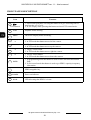
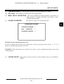
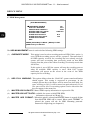
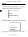
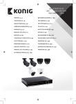
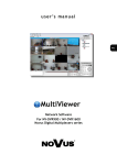
1
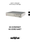
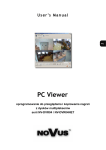
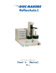
u s e r ’s m a n u a l
instrukcja obsługi
NV-DVR04
NV-DVR04NET
u s e r ’s m a n u a l
NV-DVR04
NV-DVR04NET
NV-DVR1004 / NV-DVR1004NET ver. 1.1 - User’s manual
INFORMATTIONS
EMC (89/336/EEC) and LVD (73/23/EEC ) Directives
CE Marking
Our products are manufactured to comply with requirements of following directives and
national regulations implementing the directives:
-
Electromagnetic compatibility EMC 89/336/EEC with further amendments.
Low voltage LVD 73/23/EEC with further amendment. The Directive applies to electrical
equipment designed for use with a voltage rating of between 50VAC and 1000VAC as well as
75VDC and 1500VDC.
WEEE Directive 2002/96/EC
Information on Disposal for Users of Waste Electrical and Electronic Equipment
This appliance is marked according to the European Directive on Waste Electrical and
Electronic Equipment (2002/96/EC) and further amendments. By ensuring this product is
disposed of correctly, you will help to prevent potential negative consequences for the
environment and human health, which could otherwise be caused by inappropriate waste
handling of this product.
The symbol on the product, or the documents accompanying the product, indicates that this appliance
may not be treated as household waste. It shall be handed over to the applicable collection point for the
waste electrical and electronic equipment for recycling purpose.
For more information about recycling of this product, please contact your local authorities, your
household waste disposal service or the shop where you purchased the product.
RoHS Directive 2002/95/EC
Concerning for human health protection and friendly environment, we assure that our
products falling under RoHS Directive regulations, regarding the restriction of the use of
hazardous substances in electrical and electronic equipment, were designed and
manufactured in compliance with mentioned regulation. Simultaneously, we claim that our
products were tested and do not contain hazardous substances exceeding limits which could
have negative impact on human health or natural environment.
All rights reserved © NOVUS Security Sp. z o.o.
4
NV-DVR1004 / NV-DVR1004NET ver. 1.1 - User’s manual
WARNINGS AND PRECAUTIONS
WARNING!
READ, KEEP AND FOLLOW THESE INSTRUCTIONS. ALL THE SAFETY AND
OPERATING INSTRUCTIONS SHOULD BE READ BEFORE THE PRODUCT IS
OPERATED.
WARNING:
TO REDUCE THE RISK OF FIRE OR ELECTRIC SHOCK DO NOT EXPOSE THIS UNIT TO
RAIN OR MOISTURE IF THIS UNIT IS DESIGNED FOR INDOOR USE ONLY.
WARNING!
USER IS NOT ALLOWED TO DISASSEMBLE THE CASING IF THERE ARE NO USERSERVICEABLE PARTS INSIDE THIS UNIT. ONLY AUTHORIZED SERVICE PERSONNEL
MAY OPEN THE UNIT
INSTALLATION AND SERVICING SHOULD ONLY BE DONE BY QUALIFIED SERVICE
PERSONNEL AND CONFORM TO ALL LOCAL REGULATIONS
WARNING!
DIGITAL MULTIPLEXER IS SENSITIVE TO ELECTROSTATIC DISCHARGES THEREFORE IT
SHOULD BE USED IN ACCORDANCE WITH OPERATING AND MAINTENANCE RULES FOR
DEVICES BASED ON CMOS/MOSFET TECHNOLOGY.
INFORMATION
Data included in the following user’s manual is up to date at the time of printing. Novus Security Sp z o.o. holds
exclusive rights to modify this manual. The producer reserves the rights for device specification modification
and change in the design without prior notice.
All rights reserved © NOVUS Security Sp. z o.o.
5
NV-DVR1004 / NV-DVR1004NET ver. 1.1 - User’s manual
WARNINGS AND PRECAUTIONS
1. Installation and servicing of NV-DVR1004 or NV-DVR1004NET should only be carried out by
qualified service personnel and conform to all local regulations.
2. Do not place the Multiplexer in areas where ventilation openings might be blocked or covered.
3. There are no user-serviceable parts inside this unit. Only authorized service personnel may open the
unit. The equipment should be protected from mechanical damage and kept clean at all times.
4. Protect this device from being exposed to dust and moisture. In the event of the Multiplexer coming
into direct contact with water unplug the device immediately and contact qualified service
personnel. Dusty (soiled/dirty) equipment may be the cause of fire and / or electrical shock.
5. Unplug the unit from the outlet before cleaning. This device can be cleaned only with a clean damp
cloth. Try to avoid using chemically active liquid cleaners or aerosol. In the event of strong dirt it is
allowed to use gentle cleaning lotion.
6. Power supply wires as well as signal wires should be fixed in the way that there is no risk of
mechanical damage, Please take extra caution not to overload sockets and extension cords to
prevent from the risk of fire.
7. In order to prevent the unit from damage, video channel and signal wires should be equipped with
appropriate surge protection device conforming to European Union standards. We also advice
utilizing video and data transmission protection.
8. It is not allowed to operate this device in conditions not complying with exploitation requirements
in the range of power supply, relative air humidity or air temperature..
9. Metal objects cannot be put inside the device. It can cause major malfunction and/or damage the
unit. In the event of the above, user should contact service immediately for further assistance.
All rights reserved © NOVUS Security Sp. z o.o.
6
NV-DVR1004 / NV-DVR1004NET ver. 1.1 - User’s manual
TABLE OF CONTENTS
1. FOREWORD INFORMATION ................................................................................................................8
1.1 Main characteristics.............................................................................................................................8
1.2 NV-DVR1004 and NV-DVR1004NET TECHNICAL SPECIFICATION ........................................9
2. DEVICE POWER UP ..............................................................................................................................10
2.1 Preparing the equipment for operation .............................................................................................10
2.2 Electric connectors of NV-DVR1004 back panel.............................................................................11
2.3 Electric connectors of NV-DVR1004NET back panel ....................................................................12
2.4 External Devices Connection...........................................................................................................13
2.5 HDD Installation..............................................................................................................................15
2.5.1 Swappable bay HDD installation .........................................................................................15
2.5.2 Internal HDD installation (inside the Multiplexer) ...............................................................15
2.6 Device power on and power off. ......................................................................................................16
3. FRONT PANEL DESCRIPTION ...........................................................................................................17
3.1 NV-DVR1004 front panel description ............................................................................................17
3.2 NV-DVR1004NET front panel description.....................................................................................19
4. DEVICE MENU........................................................................................................................................21
4.1 System..............................................................................................................................................22
4.2 Cameras............................................................................................................................................24
4.3 Recording .........................................................................................................................................25
4.4 Alarm setup ......................................................................................................................................27
4.5 Schedule ...........................................................................................................................................28
4.6 Event List .........................................................................................................................................29
4.7 HDD Management ...........................................................................................................................30
4.8 Network setup ..................................................................................................................................31
4.9 Default setup ....................................................................................................................................32
5. RECORD...................................................................................................................................................33
6. PLAYBACK..............................................................................................................................................34
6.1 Time Search .....................................................................................................................................34
6.2 Searching Recorded Data From The Event List ...............................................................................35
7. BACKUP ...................................................................................................................................................36
7.1. HDD backup on PC..........................................................................................................................36
7.2. Compact Flash Backup (NV-DVR-1004NET only).........................................................................36
7.2.1 Single Image Backup ............................................................................................................36
7.2.2 AVI Backup ..........................................................................................................................37
8. ALARM DEVICES INPUTS AND OUTPUTS CONNECTION .........................................................38
9. SPEED DOME CAMERA - CONNECTION AND CONTROL (NV-DVR1004NET ONLY)...........39
9.1 Novus Speed Dome Camera Connection ..........................................................................................39
9.2 Camera Control .................................................................................................................................41
10. NETWORK FUNCTION (NV-DVR1004NET)....................................................................................42
10.1 Computer Hardware Requirements ...............................................................................................42
10.2 Network Settings Configuration .....................................................................................................43
10.3 Initiating Connection.......................................................................................................................44
10.4 User Interface View ........................................................................................................................45
10.5 User Interface Function Description................................................................................................45
10.5.1 Display Settings ...................................................................................................................45
10.5.2 Transmission Speed .............................................................................................................46
10.5.3 Saving images on PC ..........................................................................................................47
10.5.4 Network Applet Configuration.............................................................................................49
10.5.4.1 Multiplexer Logs - system registry........................................................................49
10.5.4.2 System Settings .....................................................................................................49
10.5.4.3 User Accounts Management..................................................................................50
10.5.4.4 Network Connection Parameters ..........................................................................50
10.5.4.5 Alarm Event Notification ......................................................................................51
10.5.6 Multiplexer Remote Control ......................................................................................................52
All rights reserved © NOVUS Security Sp. z o.o.
7
NV-DVR1004 / NV-DVR1004NET ver. 1.1 - User’s manual
FOREWORD INFORMATION
1.
FOREWORD INFORMATION
Digital Multiplexer NV-DVR1004 / NV-DVR1004NET was designed specifically to work in CCTV
surveillance systems. This device incorporates the advantages of digital image recording with the
simplicity of installation and operation of time lapse recorders. This device utilizes very effective
compression method, ensuring high quality and detailed images.
1.1 Main characteristics.
User friendly interface, with functions known from analog multiplexers;
The simplicity and convenience of using HDD instead of video tapes;
Immediate access to recorded material;
Menu access protected by password;
M-JPEG compression algorithm with various image quality settings;
Schedule recording with selection of mode and recording speed;
The possibility of installing two HDD 3.5’’ IDE, one of them placed in swappable bay;
Simultaneous real time display of all channels;
Adjustable recording speed, up to 25 fields per second (PAL);
Alarm recording function;
Motion detection function;
The possibility of remote control and viewing the images using the Ethernet (protocol TCP/IP)
(NV-DVR1004NET only);
Files backup feature (JPG, AVI format); available methods: Compact Flash memory card backup,
PC backup, network backup (NV-DVR1004NET only);
PTZ cameras control using front panel buttons and network applet (NV-DVR1004NET only);
All rights reserved © NOVUS Security Sp. z o.o.
8
NV-DVR1004 / NV-DVR1004NET ver. 1.1 - User’s manual
NV-DVR04 and NV-DVR04NET TECHNICAL SPECIFICATION
1.2. NV-DVR04 and NV-DVR04NET TECHNICAL SPECIFICATION
NV-DVR1004
NV-DVR1004NET
simplex
Multiplexer mode
Video inputs
4 loop-through (BNC inputs), 1Vp-p/75 Ω
Video output
1 main monitor output (BNC)
Alarm inputs
4
Alarm output
1, relay
Recording resolution
640 x 272
Compression algorithm
M-JPEG
scheduled, alarm / motion recording
Recording modes
up to 100 images /s (live display)
Display speed
Motion detection
2 zones, adjustable zone's size and sensitivity
Recording schedule
record mode selection (continuous, alarm or no recording) for each hour of a day
Recording searching
time / date search or event search
up 64 events per HDD
Event log
Display format
1, 4
Video loss detection
yes
up to 2 HDD's (up to 400GB each),
one in HDD swappable bay
HDD
Recording backup
External backup
PTZ control
PTZ protocols
Control
PC backup by means of PC Viewer
PC backup by means of PC Viewer,
Compact Flash backup,
network backup
1 x RS-485 - for PTZ control
LAN. 1 x RJ-45,
1 x RS-485 - for PTZ control
by means of front panel buttons
by means of front panel buttons
or network
Novus-C, Novus-C1, Novus-C2, Pelco-D
Novus-C, Novus-C1, Novus-C2, Pelco-D
front panel buttons
front panel buttons, network
multilingual OSD
Menu
one admin password (4 digits)
Password authorization
hardware watchdog
Auto system recovery
230 VAC
Power supply
Power consumption
approx. 16 VA w/o HDD, approx. 40VA with 1 HDD, approx. 50 VA with 2 HDD's
4 kg
Weight
0°C~ +40°C;
Operating temperature
0%~80~(without condensation)
Operating relative humidity
All rights reserved © NOVUS Security Sp. z o.o.
9
NV-DVR1004 / NV-DVR1004NET ver. 1.1 - User’s manual
DEVICE POWER UP
2. DEVICE POWER UP
2.1 Preparing the equipment for operation.
Please take extra caution when unpacking the device.
Please ensure that following items are included in the package:
Digital Multiplexer NV-DVR04 or NV-DVR04NET
Net cross cable for Multiplexer-PC
connection
(NV-DVR1004NET only)
HDD Swappable Bay
lock-keys
Power Supply Cord
u s e r ’s m a nu a l
i n st r u k c j a ob s ł u gi
NV-DVR04
NV-DVR04NET
User’s Manual
CD containing manual
and software
Compact Flash Card
(NV-DVR1004NET only)
Compact Flash Card Reader
(NV-DVR1004NET only)
If the equipment has been damaged during transport, the contents of package should be packed back to
the original box. Contact the supplier for further assistance.
WARNING !
It is not allowed to power on the equipment directly after it has been brought from a place of low
temperature. If the device has been brought from the area of lower temperature the user should
wait until the equipment warms up slowly and reaches the room temperature.
Condensation of moisturized air may cause short circuit and damage the device.
All rights reserved © NOVUS Security Sp. z o.o.
10
NV-DVR1004 / NV-DVR1004NET ver. 1.1 - User’s manual
DEVICE POWER UP
2.2
Electric connectors on back panel of the NV-DVR04 multiplexer.
2
1
NV-DVR1004
6
5
4
3
1.
CAMERA OUT :
video loop-through output;
2.
POWER:
power switch ON/OFF;
~90~260V:
power supply socket;
RS-485,ALARM IN,
Relay:
RS-485 port for PTZ control, 4 alarm inputs, 1 alarm relay;
4.
MONITOR OUT:
main monitor connection, BNC connector
5.
CAMERA IN:
video inputs for camera connection;
3.
6.
:
cooling fan (do not block or cover!);
All rights reserved © NOVUS Security Sp. z o.o.
11
NV-DVR1004 / NV-DVR1004NET ver. 1.1 - User’s manual
DEVICE POWER UP
2.3
Electric connectors on back panel of the NV-DVR04NET multiplexer.
1
2
3
4
5
NV-DVR1004NET
8
7
6
network activity LEDs;
1.
2.
Ethernet:
RJ-45 socket for net computer connection;
3.
CAMERA OUT :
video loop-through output;
4.
MONITOR OUT:
output connections for Main monitor; user might select one of various split
screen display options, 2 Composite connectors
5.
POWER, ~100~240V:
power supply socket and power switch;
6.
RS-485,ALARM IN,
Relay:
RS-485 port for PTZ control, 4 alarm inputs, 1 alarm relay;
CAMERA IN:
video inputs for camera connection;
7.
8.
:
cooling fan (do not block or cover!);
All rights reserved © NOVUS Security Sp. z o.o.
12
NV-DVR1004 / NV-DVR1004NET ver. 1.1 - User’s manual
DEVICE POWER UP
2.4 External Devices Connection
All installation procedures should be conducted by qualified personnel.
Before device installation and operation please analyze the scheme shown below. Depending on specific user
needs and requirements each system will consist of various number of external devices. Monitors, cameras and
other devices are not included and must be purchased separately. Detailed description of devices connection is
included in next chapters of this manual.
All rights reserved © NOVUS Security Sp. z o.o.
13
NV-DVR1004 / NV-DVR1004NET ver. 1.1 - User’s manual
DEVICE POWER UP
All rights reserved © NOVUS Security Sp. z o.o.
14
NV-DVR1004 / NV-DVR1004NET ver. 1.1 - User’s manual
DEVICE POWER UP
2.5 HDD Installation
NV-DVR1004 and NV-DVR1004NET Digital Multiplexers allows to install two HDD's. One of these
disks can be installed inside the device, second might be placed in swappable bay.
NOTICE:
Producer advices utilizing HDD's manufactured by Maxtor or Hitachi.
Max. allowed capacity of single HDD is 400GB.
WARNING: Producer strongly advices against utilizing Samsung or Western Digital HDD's.
Novus does not take any responsibility for problems caused by using improper
HDD.
Before installing HDD please make sure that jumpers are set properly!
In the event of using only one HDD it must be set in MASTER mode. In the event of two HDD's, one
of them must be set in MASTER mode and the second in SLAVE mode. HDD configuration of
specified type and manufacturer is described in the HDD manual supplied with the HDD.
WARNING: Take into consideration that in case of using HDD from other device (other
multiplexer or PC) while first multiplexer booting all data is erased.
2.5.1 Swappable bay HDD installation
Before installation disconnect power supply cord.
Place the properly set HDD in swappable bay and then screw it on to the casing utilizing 4 supplied
screws. Place the swappable bay in the Multiplexer and close it with the key, attached in the package.
2.4.2 Internal HDD installation (inside the DVR)
NOTICE:
Internal HDD should be installed by qualified service personnel.
The housing of the Multiplexer can be opened only for internal HDD installing according to the
installing procedure described in this manual on page 52.
If the Multiplexer housing is opened for a different purpose the warranty is void.
All rights reserved © NOVUS Security Sp. z o.o.
15
NV-DVR1004 / NV-DVR1004NET ver. 1.1 - User’s manual
DEVICE POWER UP
2.6 Device turn on and turn off.
Before turning on the device please make sure that the power supply (voltage and frequency)
conforms to device requirements. Also make sure that the power switch is set to „0”, HDD swappable
bay is locked with the key and that the all external devices are connected properly.
WARNING: We do not advice to connect any additional devices (such us cameras, monitors, etc..)
while device operation.
Device power on is activated by switching the power switch to position „1”.
The loading procedure of the operating system takes about 30 seconds.
During this procedure various information will appear on the screen.
During this procedure please do not press any buttons on the front panel of this device.
The loading procedure is finished when camera images will appear on the Main monitor along with
their descriptions and the system time.
To power off the device stop the recording and shut down the device using power switch.
All rights reserved © NOVUS Security Sp. z o.o.
16
NV-DVR1004 / NV-DVR1004NET ver. 1.1 - User’s manual
FRONT PANEL DESCRIPTION
3.
NV-DVR1004 Front Panel Description
1
2
3
4
5
8
9
10
11
13
14
15
19
20
6
7
12
16
Icon
1
2
1. Channel 2 selection.
2. Password input, digit 2.
3
1. Channel 3 selection.
2. Password input, digit 3.
4
1. Channel 4 selection.
2. Password input, digit 4.
2
3
4
5
Quad
6
Rec
7
Rew Search
8
STOP
18
Function
1. Channel 1 selection.
2. Password input, digit 1.
1
17
Quad display selection (2x2).
Recording ON button;
Rewind playback. Pressing that button will give following rewind speeds:
x2, x8, x16.
Playback stop.
Pause. Press that button in playback mode to play field by field.
9
Pause
All rights reserved © NOVUS Security Sp. z o.o.
17
NV-DVR1004 / NV-DVR1004NET ver. 1.1 - User’s manual
FRONT PANEL DESCRIPTION
Icon
10
F.Fwd Search
11
12
13
Function
1. Fast Forward playback. Pressing that button will give following fast forward speeds: x2, x8, x16.
2. In live display mode pressing that button activates PTZ control mode.
PLAY
Playback menu entering.
MENU
On Screen Display menu activating;
1. "Left" cursor button
2. In PTZ mode that button moves left the camera.
1. "Up" cursor button
2. In PTZ mode that button moves up the camera.
1. "Right" cursor button
2. In PTZ mode that button moves right the camera.
16
1. "Down" cursor button
2. In PTZ mode that button moves down the camera.
17
ENTER
14
15
1. In programming mode that button is used to enter sub-menu and edition
field;
2. In live/record mode that button is used to get HDD’s capacity/occupancy
information
HDD swappable bay.
18
19
POWER
20
H.D.D.
Power on indicator.
LED informing that HDD’s is in use.
All rights reserved © NOVUS Security Sp. z o.o.
18
NV-DVR1004 / NV-DVR1004NET ver. 1.1 - User’s manual
FRONT PANEL DESCRIPTION
3.2
NV-DVR1004NET Front Panel Description
1
2
3
4
5
8
9
10
11
13
14
15
20
21
6
7
12
16
Icon
1
2
1. Channel 2 selection.
2. Password input, digit 2.
3
1. Channel 3 selection.
2. Password input, digit 3.
4
1. Channel 4 selection.
2. Password input, digit 4.
2
3
4
5
Quad
6
Rec
7
Rew Search
8
STOP
18
19
Function
1. Channel 1 selection.
2. Password input, digit 1.
1
17
Quad display selection (2x2).
Recording ON button;
Rewind playback. Pressing that button will give following rewind speeds:
x2, x8, x16.
Playback stop.
Pause. Press that button in playback mode to play field by field.
9
Pause
All rights reserved © NOVUS Security Sp. z o.o.
19
NV-DVR1004 / NV-DVR1004NET ver. 1.1 - User’s manual
FRONT PANEL DESCRIPTION
Icon
10
F.Fwd Search
11
Entering playback menu.
MENU
On Screen Display menu activating;
1. "Left" cursor button
2. In PTZ mode that button moves left the camera.
1. "Up" cursor button
2. In PTZ mode that button moves up the camera.
1. "Right" cursor button
2. In PTZ mode that button moves right the camera.
1. "Down" cursor button
2. In PTZ mode that button moves down the camera.
14
15
16
17
1. Fast Forward playback. Pressing that button will give following fast forward speeds: x2, x8, x16.
2. In live display mode pressing that button activates PTZ control mode.
PLAY
12
13
Function
COPY
ENTER
1. In programming mode that button is used to enter sub-menu and edition
field;
2. In live/record mode that button is used to get HDD’s capacity/occupancy
information
3. In playback mode that button activate CF backup.
18
Compact Flash card slot.
19
HDD swappable bay.
20
POWER
21
H.D.D.
Power on indicator.
LED informing that HDD’s is in use.
All rights reserved © NOVUS Security Sp. z o.o.
20
NV-DVR1004 / NV-DVR1004NET ver. 1.1 - User’s manual
URUCHOMIENIEDEVICE
URZĄDZENIA
MENU
4.
DEVICE MENU
Digital Multiplexers NV-DVR1004NET and NV-DVR1004NET are equipped with multi level OSD
(on screen display) sub-menus. This menus are used to program settings and execute functions such us
playback or copying. Menu is displayed in English.
Notice: Device OSD menu is available only while recording is inactive (see chapter 5).
In order to enter device menu press MENU button.
SETUP MENU
SYSTEM SETUP
CAMERA SETUP
RECORD SETUP
ALARM SETUP
SCHEDULE RECORD
EVENT LIST
HDD MANAGEMENT
NETWORK SETUP
DEFAULT SETUP
EXIT
PRESS [UP/DOWN] TO MOVE [MENU] TO EXIT
[RIGHT/LEFT] TO SELECT
Main menu consists of 9 sub-menus. The contents of sub-menus are described on following pages
of this manual.
This buttons are used to select menu items.
Selected item is pointed by these icons , or .
Press or button in order to confirm the selection, enter the sub-menu or to modify selected value.
Exiting the menu accepts and saves inputted modifications.
In order to leave selected menu or to return to the higher level menu from individual sub-menus and
modification fields EXIT option should be selected and ENTER button must be pressed. Pressing
MENU button acts similar to the procedures described above.
NOTICE: In case factory default OSD language is different than desired press MENU button, select
first menu item, press ENTER, select 4th menu item and choose desired language, exit from menu. An
example below shows changing language from Polish to English.
MENU GŁÓWNE
USTAWIENIA SYSTEMOWE
SYSTEM
KAMERY
NAGRYWANIE
ALARMY
HARMONOGRAM
REJESTR ZDARZEŃ
DYSKI
SIEĆ
USTAWIENIA FABRYCZNE
WYJŚCIE
ADRES URZĄDZENIA
USTAWIENIA ZEGARA
FORMAT DATY
WYŚWIETLAJ ZEGAR
JĘZYK
BLOKADA PRZYCISKÓW
HASŁO WEJŚCIA DO MENU
ZMIANA HASŁA
SYSTEM TELEWIZJI
WYJŚCIE
[GÓRA, DÓŁ] - WYBÓR [MENU] - WYJŚCIE
[PRAWO, LEWO] - WEJŚCIE DO PODMENU
01
RR/MM/DD
WŁ
ENGLISH
WŁ
WŁ
PAL
[GÓRA, DÓŁ] - WYBÓR [MENU] - WYJŚCIE
[PRAWO, LEWO] - WEJŚCIE LUB ZMIANA
All rights reserved © NOVUS Security Sp. z o.o.
21
NV-DVR1004 / NV-DVR1004NET ver. 1.1 - User’s manual
DEVICE MENU
4.1 System Setup
SYSTEM SETUP
DVR ID NUMBER
SET TIME/DATE
TIME DISPLAY MODE
TIME DISPLAY
LANGUAGE SELECT
KEY LOCK
MENU SETUP PROTECTION
CHANGE PASSWORD
SYSTEM SELECT
EXIT
1
YY/MM/DD
ON
ENGLISH
ON
ON
PAL
PRESS[UP,DOWN] TO MOVE [MENU] TO EXIT
[RIGHT, LEFT] TO SELECT
Utilizing SYSTEM SETUP menu following system settings may be applied:
(1)
DVR ID NUMBER:
DVR id; It is needed when using external keyboard to remote
control DVR (this option is inaccessible now)
(2)
SET TIME DATE:
after selecting this item and pressing ENTER button the time/date
menu appears.
TIME
2005/MAY/10 13:59:46 TUE
PRESS [RIGHT, LEFT] TO MOVE
[UP, DOWN] TO CHANGE
[MENU] TO EXIT
(3)
TIME DISPLAY MODE:
This option allows to define time/date format: YY/MM/DD;
MM/DD/YY; DD/MM/YY.
(4)
TIME DISPLAY:
If this option is set to ON, time will be displayed on the upper part
of the screen.
All rights reserved © NOVUS Security Sp. z o.o.
22
NV-DVR1004 / NV-DVR1004NET ver. 1.1 - User’s manual
DEVICE MENU
(5)
LANGUAGE SELECT: OSD language selection; Polish and English are available
(6)
KEY LOCK : Select ON to lock (deactivate) front panel buttons.
(7)
MENU SETUP PROTECTION: After selection ON menu button operation is protected by 4
digits password. Together with Key Lock feature it gives
complete unit protection.
(8)
CHANGE PASSWORD:
This option is used to set a 4 digit password.
PASSWORD CHANGE
CURRENT PASSWORD : - - - NEW
PASSWORD
:----
PASSWORD CONFIRM : - - - -
NOTICE: Factory default password: 1111.
In order to change the password you should input correctly present password (using 1, 2, 3, 4
buttons ), and then input two times a new one.
WARNING: Please don't forget new password. In order to recover forgotten password service help
is indispensable.
(9)
SYSTEM SELECT: This option is used to select TV system standard. You can select PAL or
NTSC
All rights reserved © NOVUS Security Sp. z o.o.
23
NV-DVR1004 / NV-DVR1004NET ver. 1.1 - User’s manual
DEVICE MENU
4.2 Cameras
CAMERA SETUP
CAMERA SELECT
CAMERA RECORD
MOTION SENSITIVITY
MOTION AREA SETUP
BRIGHTNESS
CONTRAST
HUE
CAMERA TITLE EDIT
EXIT
PRESS [UP/DOWN] TO MOVE
[RIGHT/LEFT[ TO SELECT
[ [ CAM1 ] ]
ON
2
STANDARD
STANDARD
STANDARD
[MENU] TO EXIT
In CAMERA SETUP menu following settings can be set for each video channel:
(1)
CAMERA SELECT : This option is used to select specific channel number for the camera, of
which settings should be displayed or modified
(2)
CAMERA RECORD: If this option is set to OFF the image from selected camera will not be
recorded however it still will be displayed on the screen. In order to record image from selected
camera set this option to ON;
(3)
MOTION SENSITIVITY: This option allows to define the sensitivity of motion detection. Using
this option allows to evade unnecessary false alarms caused for example by moving leafs etc..
This option can be adjusted in the range from 1 to 6. The higher value of motion detection makes
it more sensitive.
(4)
MOTION AREA SETUP: Using this option allows to define two rectangular blocks for motion
detection. In order to display buttons description press QUAD. Three initial block types can be
defined: 1 - blocks with smallest area, 2 - blocks with default area, 3 - blocks with biggest area.
Each block can be extended and placed according to user individual needs. After selecting initial
block’s area press cursor keys to place it in required screen place. Then press PLAY and use
cursor keys to extend it. To change second block press PLAY once more and act as at first block.
Notice! Only marked area is analyzed for motion detection.
(5)
BRIGHTNESS
CONTRAST
HUE:
This menu options allow to adjust the parameters of displayed image to user
individual needs and requirements. The default value is 50;
Notice: Adjusting the parameters of image also take effect on recordings.
(6)
CAMERA TITLE EDIT: This option allows to edit camera title. In order to edit camera title
place cursor “^” under demanded character and press PLAY. Follow this action until all
characters will be selected. Press MENU to finish.
All rights reserved © NOVUS Security Sp. z o.o.
24
NV-DVR1004 / NV-DVR1004NET ver. 1.1 - User’s manual
DEVICE MENU
4.3 Recording
RECORD SETUP
RECORD MODE
NORMAL RECORD FPS
ALARM RECORD FPS
ALARM RECORD DWELL
RECORD QUALITY
EXIT
PRESS [UP/DOWN] TO MOVE
[RIGHT/LEFT[ TO SELECT
MUX
12P
25P
5 SEC
HIGH
[MENU] TO EXIT
In RECORD SETUP menu following settings can be adjusted:
(1)
(2)
(3)
(4)
RECORD MODE: This option allows to define recording mode. Multiplexer mode (MUX)
means that images from each channel are stored one after another. Later on
full screen as well as quad playback are available. Quad mode (QUAD)
means that there are all channels recorded in the same time in quad
division. Later on there is only quad playback mode available.
NORMAL RECORD FPS: This option is used to set recording speed for normal and schedule
recording. Speed values are expressed in fields per second rate.
Following values are available: 25, 12, 8, 6, 4, 3, 2, 1.
Recording speed applies to entire Multiplexer. Depending on
number of recording cameras the Multiplexer resources are equally
divided between each camera.
ALARM RECORD FPS: This option is used to set recording speed during alarm mode
(alarm inputs and motion detection). Speed values are expressed in
fields per second rate. Following values are available: 25, 12, 8, 6,
4, 3, 2, 1. Recording speed applies to entire Multiplexer.
Depending on number of recording cameras the Multiplexer
resources are equally divided between each camera.
ALARM RECORD DWELL: Time defined in seconds describing the alarm duration.
This setting allows to record in alarm mode for longer periods of
time than the duration of alarm event;
All rights reserved © NOVUS Security Sp. z o.o.
25
NV-DVR1004 / NV-DVR1004NET ver. 1.1 - User’s manual
DEVICE MENU
(4)
RECORD QUALITY: This option defines the recording image compression level along with
the recording quality level. 4 quality levels are available: LOW,
MEDIUM, HIGH, BEST. The total duration of recording time for
specific HDD depends on recording quality settings. Information
concerning recording time might be obtained from DVRcalc our freeware
software available as well on CD and Novus web site.
(5)
MOTION EVENT MIGRATION: This option allows adding motion detection events to the
Event List. This setting has no influence on motion
detection itself. It is only Event list operating rule.
NOTICE: Event List can store only latest 64 events for each HDD. You should set MOTION
EVENT MIGRATION as OFF to store more important logs (e.g. power off) for longer
time. In other case last 64 motion detection logs will replace more important events.
All rights reserved © NOVUS Security Sp. z o.o.
26
NV-DVR1004 / NV-DVR1004NET ver. 1.1 - User’s manual
DEVICE MENU
4.4 Alarm setup
ALARM SETUP
[BUZZER]
BUZZER DWELL
VIDEO LOSS ALARM
MOTION ALARM
EXTERNAL ALARM
1SEC
ON
ON
OFF
[RELAY]
VIDEO LOSS ALARM
MOTION ALARM
EXTERNAL ALARM
OFF
ON
ON
EXTERNAL SENSOR SETUP
ALARM DISPLAY MODE
EXIT
OFF
In ALARM SETUP menu following settings can be adjusted:
Buzzer settings:
(1) BUZZER DWELL: This option is used to select buzzer dwell time after alarm detection
(2) VIDEO LOSS ALARM: If this option is set to ON, buzzer will be turned on in case of video
loss
(3) MOTION ALARM: If this option is set to ON, buzzer will be turned on in case of motion
detection
(4) EXTERNAL ALARM: If this option is set to ON, buzzer will be turned on in case of external
alarm
Relay settings:
(1) VIDEO LOSS ALARM: If this option is set to ON, relay will be activated in case of video loss.
(2) MOTION ALARM: If this option is set to ON, relay will be activated in case of motion detection
(3) EXTERNAL ALARM: If this option is set to ON, relay will be activated in case of external
alarm
EXTERNAL SENSOR SETUP: This option is used to configure alarm inputs. Each input can be set
up as a normally opened, normally closed and inactive
ALARM DISPLAY MODE: If this option is set to ON, fullscreen video will be displayed from
channel where alarm was detected.
All rights reserved © NOVUS Security Sp. z o.o.
27
NV-DVR1004 / NV-DVR1004NET ver. 1.1 - User’s manual
DEVICE MENU
4.5 Schedule record
SCHEDULE RECORD menu represents various recording modes in different time during the day.
Schedule recording can be set accurate to one hour. It is possible to set only one schedule recording that
will be valid every day.
[SCHEDULE RECORD]
OOOOAAAAAXXXXOOOAOXXOOAA
:
:
:
:
:
:
:
:
:
0
3
6
9
12
15
18
21
24
PRESS [PLAY] TO SET FOR ALL
[RIGHT/LEFT] TO MOVE [MENU] TO EXIT
[UP/DOWN] TO SELECT
Letters represent recording modes valid for given hour.
O - this option is used for continuous recording speed accordingly to values set in RECORD menu
in option NORMAL RECORD FPS , and in alarm recording mode (motion detection and external
alarms) with speed set in ALARM RECORD FPS menu.
A -
this means that recording process will occur only in the event of alarm (motion detection and
external alarms) with speed set in RECORD in ALARM RECORD FPS menu
X - this means that during specified hour the recording process will not occur.
Time line indicators are placed below the letters line. In the example above continuous recording will
be run during following hours 0-1; 3-4; 6-18 i 20-22. During this hours 1-2; 4-6 i 22-0 only alarm
recording will take effect (external alarms and motion detection)
To change whole schedule configuration press PLAY. Pressing PLAY will result in changing all letters
into “O”, “A”, “X”.
All rights reserved © NOVUS Security Sp. z o.o.
28
NV-DVR1004 / NV-DVR1004NET ver. 1.1 - User’s manual
DEVICE MENU
4.6 Event List
EVENT LIST
HARD DRIVE: MASTER
START TIME: 2005/MAY/10 15:20:16
END TIME: 2005/MAY/10 15:27:33
01 RECORD
02 RECORD
03 MOT CH1
2005/MAY/10 15:20:16
2005/MAY/10 15:30:05
2005/MAY/10 16:49:51
PRESS [UP, DOWN] TO MOVE
[QUAD] TO CHANGE HDD
[RIGHT] TO PLAY
[MENU] TO EXIT
When EVENT LIST is entered system history is available. The system registry stores events recorded
from the time of the last HDD formatting. The events are divided according to the time of occurrence.
The newest events are displayed as first. In the case when there are more events then can be displayed
on one page additional events are displayed on following system registry pages.
Information is divided in columns;
The first column contains event number, the second - event date, the third - event time, the fourth the event camera number, (-- this sign means that selected event concerns entire system).
In the fifth column specific shortcut describing event type is placed:
−
−
−
MOT CH1 motion detection activation on channel 1
RECORD recording initiation
ALM CH1 alarm on the alarm input on channel 1
POWER system reboot due to power failure
In the middle of the screen there is info which HDD (MASTER or SLAVE) Event list concerns.
Pressing QUAD toggles between HDD’s.
NOTICE: Event List can store only latest 64 events for each HDD. You should set MOTION
EVENT MIGRATION as OFF to store more important logs (e.g. power off) for longer
time. In other case last 64 motion detection logs will replace more important events.
All rights reserved © NOVUS Security Sp. z o.o.
29
NV-DVR1004 / NV-DVR1004NET ver. 1.1 - User’s manual
DEVICE MENU
4.7 HDD Management
[HDD MANAGEMENT]
OVERWRITE ENABLE
HDD FULL WARNING
MASTER HDD CAPACITY
MASTER HDD LEFT RATIO
MASTER HDD FORMAT
SLAVE HDD CAPACITY
SLAVE HDD LEFT RATIO
SLAVE HDD FORMAT
EXIT
NO
20 %
76GB
73GB 97%
N/A
N/A
PRESS [UP/DOWN] TO MOVE [MENU] TO EXIT
[RIGHT/LEFT] TO SELECT
The HDD MANAGEMENT menu is used to define following HDD settings:
(1)
OVERWRITE MODE: This option is used to select recording mode on HDD. If this option is
set to YES the recording process will be „repeated”. That meas that if
all HDD capacity reserved for recording has been already used the
system will start overwriting data previously stored on that HDD
(staring from the point of the oldest recording). Previously stored data
will be lost;
If this option is set to NO the system will stop the recording process
when all available HDD capacity is used. “Disk Full” system
notification will appear on the screen in the event of low HDD
capacity left for recording;
(2)
(3)
(4)
(5)
HDD FULL WARNING: This option defines when the “Disk Full” system sound notification
should appear. This setting is expressed in percentage. In the
example shown above the buzzer will be turned on when disk free
space will drop to 20%. It will be turned on again when only 5% of
free space will be left. If overwriting option is active this menu line
does not appear in the menu list;
MASTER HDD CAPACITY: Master HDD capacity information is expressed in GB;
MASTER HDD LEFT RATIO: available free space on MASTER HDD,
information expressed in GB and %;
MASTER HDD FORMAT: When this option is selected and ENTER button is pressed all data
from MASTER HDD will be erased. When option FORMAT is
selected the system will ask for HDD formatting password.
Password is 4 digits long (see chapter 4.1)
All rights reserved © NOVUS Security Sp. z o.o.
30
NV-DVR1004 / NV-DVR1004NET ver. 1.1 - User’s manual
DEVICE MENU
(6)
(7)
(8)
SLAVE HDD CAPACITY: Slave HDD capacity information expressed in GB;
SLAVE HDD LEFT RATIO: available free space on SLAVE HDD, information expressed
in GB and %;
SLAVE HDD FORMAT:
When this option is selected and ENTER button is pressed all data
from SLAVE HDD will be erased. When option FORMAT is
selected the system will ask for HDD formatting password.
Password is 4 digits long (see chapter 4.1)
4.8. Network setup (only for NV-DVR1004NET)
NETWORK SETUP
IP ASSIGNMENT
IP ADDRESS
SUBNET MASK
GATEWAY
EXIT
MANUAL/AUTOMATIC
[192.168.001.124]
[255.255.255.000]
[192.168.001.040]
PRESS[UP,DOWN] TO MOVE [MENU] TO EXIT
[RIGHT, LEFT] TO SELECT
The NETWORK SETUP menu is used to define following HDD settings:
(1)
(2)
(3)
(4)
IP ASSIGNMENT: manual and automatic (via DHCP) IP assignment can be selected in this
option
IP ADDRESS: in this option IP address can be selected
SUBNET MASK: in this option subnet mask can be selected
GATEWAY: in this option gateway can be selected
All rights reserved © NOVUS Security Sp. z o.o.
31
NV-DVR1004 / NV-DVR1004NET ver. 1.1 - User’s manual
DEVICE MENU
4.9 Default setup.
DEFAULT SETUP
SET FOR ALL
SYSTEM SETUP
CAMERA SETUP
RECORD SETUP
ALARM SETUP
EXIT
OFF
ON
ON
OFF
OFF
PRESS [UP,DOWN] TO MOVE [MENU] TO EXIT
[RIGHT, LEFT] TO CHANGE
The DEFAULT SETUP menu is used to define which settings should be restored to factory default
setup.
(1)
(2)
(3)
(4)
(5)
SET FOR ALL: setting this option causes changing all options.
SYSTEM SETUP: If this option is set to ON, system settings will be restored to default
CAMERA SETUP: If this option is set to ON, camera settings will be restored to default
RECORD SETUP: If this option is set to ON, record settings will be restored to default
ALARM SETUP: If this option is set to ON, alarm settings will be restored to default
In order to restore selected settings, exit menu and confirm overwriting.
All rights reserved © NOVUS Security Sp. z o.o.
32
NV-DVR1004 / NV-DVR1004NET ver. 1.1 - User’s manual
RECORD SETUP
5. RECORD SETUP
NV-DVR04 and NV-DVR04NET Multiplexers can automatically restore recording mode after
rebooting and after exiting menu.
To stop recording press STOP . To activate recording button should be pressed.
Inscription REC is displayed when recording is active. Following letters describe recording mode:
[M] - multiplexer, [Q] - quad. In right upper corner there is recording speed information displayed.
Please notice that only active channels are recorded.
Current recording mode valid for each channel is displayed in the centre of the screen.
Notice: Available recording mode for each channel and for each hour are set in SCHEDULE
RECORD menu.
All rights reserved © NOVUS Security Sp. z o.o.
33
NV-DVR1004 / NV-DVR1004NET ver. 1.1 - User’s manual
PLAYBACK
6. PLAYBACK
Digital Multiplexers NV-DVR1004 and NV-DVR1004NET allows to find desired recordings in two
ways. First search option can be done by inputting specified time and date. Second search option is
possible by viewing the event registry and playback of recordings related to the selected event. Because
devices operate as a simplex, to start playback recording must be turned off before.
In order to display playback menu PLAY button should be pressed.
PLAYBACK TYPE SELECT
TIME SEARCH
EVENT LIST
EXIT
PRESS[UP,DOWN] TO MOVE [MENU] TO EXIT
[RIGHT, LEFT] TO CHANGE
6.1 Time Search
When this option is selected date and time menu will appear on the screen allowing to playback
specified data. Additionally available recording range information will appear.
TIME SEARCH
HARD DRIVE: MASTER
START TIME: 2005/MAY/10 09:20:16
HARD DRIVE: MASTER
START TIME: 2005/MAY/10 15:20:16
END TIME: 2005/MAY/11 09:27:23
HARD DRIVE: SLAVE
START TIME: 2005/MAY/10 15:20:16
END TIME: 2005/MAY/11 09:27:23
PRESS [RIGHT, LEFT] TO MOVE [MENU] TO EXIT
[UP, DOWN] TO CHANGE
Information may depends on the number of installed HDDs or recording position on HDD and
recording mode (overwrite).
All rights reserved © NOVUS Security Sp. z o.o.
34
NV-DVR1004 / NV-DVR1004NET ver. 1.1 - User’s manual
PLAYBACK
To toggle between HDD’s contents press ENTER button.
TIME SEARCH
HARD DRIVE: MASTER
START TIME: 2005/MAY/10 09:20:16
HARD DRIVE: MASTER
START TIME: 2005/MAY/10 15:20:16
END TIME: 2005/MAY/11 09:27:23
HARD DRIVE: SLAVE
START TIME: 2005/MAY/10 15:20:16
END TIME: 2005/MAY/11 09:27:23
PRESS [RIGHT, LEFT] TO MOVE [MENU] TO EXIT
[UP, DOWN] TO CHANGE
To start playback recordings from specific time selecting proper HDD (using QUAD) button
is required (if there are two HDD’s). Then desired date and time should be set using cursor buttons.
Playback starts after pressing PLAY button.
Default playback display is quad mode.
If played data was recorded in MUX mode there is channel selection and full screen display mode
available.
During playback all playback control buttons are available (see description in chapter 3)
6.2 Searching Recorded Data From The Event List.
When this option is selected Event list will appear on the screen allowing to playback specified data
related to system events.
To change HDD press QUAD. Desired event should be selected using cursor buttons . Playback
starts after pressing right cursor or PLAY button.
Event logs description are listed in chapter 4.6
Default playback display is quad mode.
If played data was recorded in MUX mode there is channel selection and full screen display possible.
During playback all playback control buttons are available (see description in chapter 3)
All rights reserved © NOVUS Security Sp. z o.o.
35
NV-DVR1004 / NV-DVR1004NET ver. 1.1 - User’s manual
BACKUP
7. BACKUP
7.1. HDD backup on PC.
PC Viewer software allows to review and backup recordings from swappable HDD on PC.
Detailed information is included in the manual of PC Viewer. PC Viewer software and manuals are
included on CD.
7.2. Compact Flash Backup (NV-DVR1004NET only)
Digital Multiplexer NV-DVR1004NET is equipped with an interface allowing to connect Compact
Flash memory cards. The memory card input socket is placed on the front panel next to the HDD bay.
Notice: Novus company guarantees proper operation only with Transcend CF cards supplied in
DVR package.
Notice: During backup process computer network connection is prohibited. It is advised
to disconnect the device physically from the net for the duration of backup process
if there is a risk of incoming net connection.
Notice: Backup can be proceeded only in playback mode. Because device operates as a simplex,
take into consideration that during backup process recording mode is unavailable.
possible.
Notice: Recordings proceeded in QUAD mode can be backup only as a “quad pictures”. Only
recordings proceeded in MUX mode allow selecting each channel.
The memory card should be inserted with caution to prevent the memory card socket from being
damaged. The memory card should be inserted only in one way - the sticker with company logo and
capacity should be faced left.
All rights reserved © NOVUS Security Sp. z o.o.
36
NV-DVR1004 / NV-DVR1004NET ver. 1.1 - User’s manual
BACKUP
7.2.1 Single Image Backup
Insert the memory card inside card slot before starting the backup process.
If memory card is inserted into the device a sign in the lower left corner is displayed.
To backup single image in JPEG file, the playback of desired data must be run then selected camera
must be displayed in full screen mode and finally the image must be frozen (pause button) in desired
place. Using and buttons allows to select exact desired images. When desired image is selected
press COPY button. Following massage CF CARD TESTING PLEASE WAIT will be displayed.
After short time message SAVE OK will appear. Additionally on the bottom of the screen memory
card capacity information will appear. For example information 23MB / 121M 81% means that
currently 81% is free from the total available of 121MB. When the backup process is completed user
can select next image or finish backup simply by taking out the memory card (message CF CARD
REMOVED will appear on the screen).
7.2.2 AVI Backup
Insert the memory card inside card slot before starting the backup process.
If memory card is inserted into device in the lower left corner sign CF is displayed.
To backup a video sequence in the AVI format playback of desired data must be run and selected
camera must be displayed in full screen mode. Finally, select the desired backup time and press button
COPY.
After short time message BACKUP TO CF CARD AVI FILE will appear. Additionally on the bottom
of the screen below CF sign AVI sign will appear. This means that backup process is currently running.
During this backup process user may increase or decrease the playback speed.
To finish backup of selected data button COPY should be pressed again. The following message will
appear on the screen:
CF CARD PROCESSING, PLEASE WAIT.....
During the backup process the memory card must remain in the memory card reader at all times.
Similar information appears automatically after each minute of backup.
In order to take out the memory card the following information must appear on the screen.
SAVE OK
When the backup process is completed, user can select next video sequence or finish backup simply
by taking out the memory card (message CF CARD REMOVED will appear on the screen)
Notice: When video sequence that user wants to backup is longer then one minute the device will
automatically divide the backup data into files of duration time of 1 minute (size 2-3 MB).
If backup failed message SAVE FAIL PLEASE CHECK CF CARD will be displayed.
In such a case try to backup again after 30 sec. If another attempt fails, it means that CF card
is damaged or incompatible.
All rights reserved © NOVUS Security Sp. z o.o.
37
NV-DVR1004 / NV-DVR1004NET ver. 1.1 - User’s manual
ALARM INPUTS AND OUTPUTS CONNECTION
ODTWARZANIE
8. ALARM INPUTS AND OUTPUTS CONNECTION
Digital Multiplexers NV-DVR1004 and NV-DVR1004NET are equipped with 4 alarm inputs which
allow to connect external devices. Output relay allows to control external devices e.g. sirens.
Do not exceed maximum current of 200mA.
When external alarm event occurs (any alarm input shorted with ground) Multiplexer will switch
display to the quad mode, ALM sign will appear on the screen, alarm output relay will be closed and
alarm event will be added to the Event list.
To automatically switch the device to alarm recording mode manual or schedule recording must be
initiated. Junction for cable connection is equipped with handy, removable clamp junctions terminal.
On this terminal also alarm output is placed. For detailed terminal description please view the image
below.
PIN
FUNCTION
ALARM IN 1
Alarm input 1
ALARM IN 2
Alarm input 2
ALARM IN 3
Alarm input 3
ALARM IN 4
Alarm input 4
GND
Ground
Relay N.C.
Alarm output
normally close
Relay N.O.
Alarm output
normally open
COM
Alarm output
common pin
.
All rights reserved © NOVUS Security Sp. z o.o.
38
NV-DVR1004 / NV-DVR1004NET ver. 1.1 - User’s manual
SPEED DOME CAMERA - CONNECTION AND CONTROL
9. SPEED DOME CAMERA - CONNECTION AND CONTROL
Digital Multiplexer NV-DVR1004NET allows to control up to 4 speed dome cameras.
For camera control port RS-485 is used. Control lines are connected in a “daisy chain” way. Camera
controlled by user by buttons placed on front panel or by utilizing net software. For proper operation
each speed dome camera must have individual system address. Following rule should be applied:
camera with address 1 is connected to video input nr 1, camera with address 2 connected to channel 2
and so on.
Control is done by Novus-C, Novus-C1, Novus-C2 or Pelco-D protocol.
Warning: All cameras in the system should have identical protocol and transmission speed
9600BPS (please view Speed Dome Camera Manuals).
Camera connection description applies to Novus camera connections. In order to connect cameras of
other producers technical department should be contacted and user should familiarize himself with
specific camera manual.
9.1 Novus Speed Dome Camera Connection
Speed Dome Camera control lines are connected in a “daisy chain” way with the use of twisted pair
cable (UTP 5th class). The maximum length of line can not exceed 1200m.
The telemetry control signals are lead to junction with the symbol RS-485. .
T+
T-
Should be connected with Rx + / Tx+ in the camera
Should be connected with Rx - / Tx- in the camera
All rights reserved © NOVUS Security Sp. z o.o.
39
NV-DVR1004 / NV-DVR1004NET ver. 1.1 - User’s manual
SPEED DOME CAMERA - CONNECTION AND CONTROL
Speed Dome camera connection
Video
NV-DVR1004 or NV-DVR1004NET
max 1,5 m
24VAC +
24VAC FGND
(RX+)
RX+(TX+)
RX-(TX-)
GND
24VAC24VAC+
24VAC +
24VAC FGND
(RX+)
RX+(TX+)
RX-(TX-)
GND
24VAC24VAC+
max 1,5 m
UTP 5 max 1200m
v
v
Novus CAMA I
nr 4
Novus CAMA I
nr 1
All rights reserved © NOVUS Security Sp. z o.o.
40
NV-DVR1004 / NV-DVR1004NET ver. 1.1 - User’s manual
SPEED DOME CAMERA - CONNECTION AND CONTROL
9.2 Camera Control
To enter camera control mode, specific camera should be selected. Set display to full screen mode and
then press button
In the upper right corner sign PTZ will appear informing that Multiplexer is set to Speed Dome
Camera control mode and that some of buttons are now active as a Speed Dome control buttons.
Icon
Function
Rew Search
Zoom out
Play
Zoom in
Tilt up
Tilt down
Pan right
Pan left
Control is done in a „step” way, which means that each button press will execute one step of particular
function e.g. pan move.
When MENU button is pressed special PTZ menu will appear. Using this menu one of six camera pan
and tilt levels may be defined. Each level represents how “long” the “step” is. The higher level number
is, the bigger elementary movement is done.
Scan function is not available in cameras described above.
To exit PTZ menu MENU button should be pressed.
To exit PTZ camera control mode button
should be pressed. Sign PTZ will disappear from the
screen and Multiplexer will return to normal working mode (buttons will activate standard functions)
PTZ SETUP
> PROTOCOL TYPE: NOVUS-C
UP-DOWN SPEED: 1
LEFT-RIGHT SPEED: 1
BAUDRATE: 9600
EXIT
PRESS[UP,DOWN] TO MOVE [MENU] TO EXIT
[RIGHT, LEFT] TO CHANGE
All rights reserved © NOVUS Security Sp. z o.o.
41
NV-DVR1004 / NV-DVR1004NET ver. 1.1 - User’s manual
NETWORK CONNECTION FEATURE
10. NETWORK FUNCTION (NV-DVR1004NET ONLY)
Digital Multiplexer NV-DVR1004NET allows network connection option utilizing TCP/IP protocol.
It is required to assign static IP address for the devices.
Warning: Operation conducted via net has direct influence on local operation. For example, change of
display mode with the use of net will also change the display mode on Main monitor. This should be
kept in mind. Net connection should be limited to the minimum especially if someone is monitoring
area locally on Main monitor. This problem does not occur in the systems without local operators.
Warning: NOVUS company is not a distributor of server systems, routers, hubs, and other net devices
which have influence on proper net working. Net user or network administrator is responsible for
configuration propriety of mentioned devices .
10.1 Computer Hardware Requirements
Processor
Intel® Pentium® 1GHz (or higher)
RAM memory
Minimum 128MB
Internet browser
Internet Explorer 5.0 (or higher), with Java script set as active
Other devices required
Graphic Card, AGP x 4, 16MB
Operating System
Microsoft® Windows® 98 / ME / 2000 / XP™
All rights reserved © NOVUS Security Sp. z o.o.
42
NV-DVR1004 / NV-DVR1004NET ver. 1.1 - User’s manual
NETWORK CONNECTION FEATURE
10.2 DVR Network Settings Configuration
To configure network settings, IPInstaller software should be used. This software is provided on CD
included in the package.
To connect with Multiplexer application IPInstaller.exe, should be run. The device must be connected
with the computer using of net cross cable which is also included in the package. The Multiplexer must
be powered on. When system boot is finished Search Device button should be pressed.
On the left side in the field Device lists the name of the device will appear along with its current IP
address.
When this position is clicked on the right side net settings will appear:
−
IP Address
−
Netmask
−
Gateway
−
HTTP Port
−
MAC
The above settings can be edited (except MAC) to adjust settings to meet specific net requirements.
When configuration settings is finished save changes clicking on Submit.
Net module reboot information will appear on the screen and after short time modified devices setting
will appear.
Clicking Exit will exit application discarding changes.
All rights reserved © NOVUS Security Sp. z o.o.
43
NV-DVR1004 / NV-DVR1004NET ver. 1.1 - User’s manual
NETWORK CONNECTION FEATURE
10.3 Initiating Connection
Microsoft Internet Explorer should be used for net connection. Multiplexer IP address should be input
in the browser address bar ( IP address can be acquired with the use of application IPInstaller.exe).
If selected communication port is different than 80, after address space, colon and port number must be
typed.
Example: for connection like in the example on previous page, following IP address should be input in
the web browser address bar:
192.168.2.128 :100
During connection applet is downloaded from the device. This applet provides all Multiplexer network
functions.
Network interface should appear after a while.
Depending on Windows security settings it might be necessary to accept unknown for system Active X
format (click Yes)
Uwaga: W przypadku
problemów z ładowaniem
się appletu należy sprawdzić
czy w Opcjach
internetowych przeglądarki
w zakładce Ogólne, w
pozycji Tymczasowe pliki
internetowe / Ustawienia
wybrana jest opcja
automatycznego
sprawdzania nowszych
wersji przechowywanych
stron.
Click Yes
All rights reserved © NOVUS Security Sp. z o.o.
44
NV-DVR1004 / NV-DVR1004NET ver. 1.1 - User’s manual
NETWORK CONNECTION FEATURE
10.4 User Interface View
Following description applies to network interface version 3.14.
The tabs on the left side of the screen allow to set various configuration and operation settings. Camera
images fill the rest of the screen space. (default split screen to 4).
10.5 User Interface Function Description
10.5.1 Display Settings
In the tab Image Adjust user can adjust image display settings.
Quality option allows to select one of three levels of display quality: High, Medium, Low. Higher
quality level settings makes lower displayed images refresh rate.
Resolution option allows to select one of three resolutions: QCIF - 176x144, CIF - 360x288, VGA 640x480. The higher resolution settings are the lower displayed images refresh rate is.
Advanced option allows to select one of several image settings to correct the overall image appearance.
Buttons + (increase), - (decrease), STD (restore default settings).
These settings are: Brightness, Contrast, Saturation, Hue, Sharpness.
All rights reserved © NOVUS Security Sp. z o.o.
45
NV-DVR1004 / NV-DVR1004NET ver. 1.1 - User’s manual
NETWORK CONNECTION FEATURE
Current refresh rate and resolution is displayed on Status Bar.
To display this Status Bar press right mouse button on camera image and select Status Bar.
Right-clicking on camera images brings on the menu that allows to define the video stream display
mode in the web browser window. By default the image is „expanded” to entire available space
irrespectively of real image resolution. Actual size option restores the real image display.
With default settings, when the web browser window is decreased, only a part of camera images
is visible. depending on actual window size (the image size does not change). Resizable option should
be marked if we desire to automatically adjust image size to fit in the window actual size.
10.5.2 Transmission Speed
Operation Mode tab is used to adjust transmission speed to meet user expectations and network
capabilities.
Continuous option allows for continuous transmission with maximum speed and refresh rate .
However this will highly reduce the network capacity (around 4,5Mb/s is required).
If value number in seconds or milliseconds is input and Periodic option is marked the data will be sent
periodically (with interval set in the window). As the refresh rate will drop the network free capacity
will increase significantly.
All rights reserved © NOVUS Security Sp. z o.o.
46
NV-DVR1004 / NV-DVR1004NET ver. 1.1 - User’s manual
NETWORK CONNECTION FEATURE
10.5.3 Saving images on PC
Image Capture tab is used to activate actual image capturing function of specified numbers of single
images or video sequence from the playback/displayed stream. If camera images are displayed in quad
mode or in freeze mode, that’s exactly how it will be saved. The transmission speed and quality
of saved files depends on settings described on previous pages.
To capture single currently displayed image F12 button should be pressed and saving path should be
input/selected or Snapshot option should be selected.
To bring on Image Recording menu Recording option should be selected or F11 button should be
pressed..
All rights reserved © NOVUS Security Sp. z o.o.
47
NV-DVR1004 / NV-DVR1004NET ver. 1.1 - User’s manual
NETWORK CONNECTION FEATURE
In the field Select user must specify if captured images should be single frames (JPEG) or video
sequences (AVI) or both .
- When saving JPEG files in the field JPEG exact number of saved files can be selected.
No Limit option will save all files up to the point of manual stop (F11 button).
Number option allows to specify the number of frames which will be saved.
Size option allows to specify in kilobytes the total size of saved frames.
Time option allows to specify in seconds the capturing time.
The image capturing begins at the moment when Start button is pressed.
The files are stored in the folder selected in the field Save Path. The save path can be selected when
Save As option is clicked.
Pre Name field is used to specify prefix which will be added to each file name.
Apply option is used to save settings.
- When saving AVI files in the field AVI the number of data which will be saved can be selected.
No Limit option will save all files up to the point of manual stop (F11 button).
Number option allows to specify the number of frames in video sequence.
Size option allows to specify in kilobytes the total size of saved video sequence.
Time option allows to specify in seconds the capturing time.
The field Maximum Number of Frames in Each File allows to specify the number of frames
that files will consist of. Together with long capture time, this allows to divide video sequences into
few smaller files.
Video sequence capturing begins at the moment when Start button is pressed.
The files are stored in the folder selected in the field Save Path. The save path can be selected when
Save As option is clicked.
Pre Name field is used to specify prefix which will be added to each file name.
Apply option is used to save settings.
User is notified of current image capturing status. In the lower right corner yellow sign indicates
capturing JPEG files and red sign indicates capturing AVI files.
All rights reserved © NOVUS Security Sp. z o.o.
48
NV-DVR1004 / NV-DVR1004NET ver. 1.1 - User’s manual
NETWORK CONNECTION FEATURE
10.5.4 Network Applet Configuration
Configuration tab is used for advanced applet settings such us user accounts administration, alarm
function, etc.
10.5.4.1 Multiplexer Logs - system registry
View Log option allows to view system registry of the network interface. Multiplexer Logs lists
information of type of the event, user IP and MAC address who made modifications and the exact time
and date of the event.
10.5.4.2 System Settings
System Setting option is used to retrieve following system information and to perform system
modifications:
−
−
−
−
−
−
−
−
−
−
−
Version - network interface version information
DVR Title - device name, to enter new name input desired characters and press Change, to save
Device’s time - system time (network interface only)
Time zone - time zone
NTP Server - time synchronization server
Input new time, Synchronize with PC’s time - mark this option and click Adjust to synchronize
system clock with PC clock
Language setting - interface language selection
four channel DVR, nine channel DVR, sixteen channel DVR - model selection with which
connection is initiated (by default applet should detect automatically correct device type)
NTSC System, PAL System - TV system selection in which Multiplexer will work
Reboot DVR - network interface restart
Firmware update - Network interface update (service function)
All rights reserved © NOVUS Security Sp. z o.o.
49
NV-DVR1004 / NV-DVR1004NET ver. 1.1 - User’s manual
NETWORK CONNECTION FEATURE
10.5.4.3 User Accounts Management
User Management option is used to acquire following information and apply changes in the user
accounts and network access passwords. There are two types of users: Administrator and Guest
Administrator has full access to the system, Guest may only watch the displayed image in the display
mode set by administrator or local operator.
−
−
−
−
−
User authorization required: if Yes is selected Set is pressed the system will require authorization
confirmation during network connections
Administrator option allows to change the name and administrator password (default settings is
admin, admin) New user name is input in Username field and new password is input in Password
field. Confirm option is used to verify and confirm new settings. Modifications are confirmed by
clicking on Set & Change
Add a user or change password option is used to input new user name and password that will be
added to the list when Set & Change is clicked.
This field is also used to modify current user password when one of the existing users is selected
from the list below.
Delete user - select desired user from the list and click Delete; selected account will be erased.
However admin account can not be erased.
Current user list - the list of currently registered user accounts. From this list accounts can be
selected for modification/deletion
10.5.4.4 Network Connection Parameters
Network Setting option is used to acquire following network settings information and connection
methods:
−
LAN - network settings, Manually - manual settings input (with the use of application IPInstaller),
Automatically by DHCP - automatically set settings by DHCP server (if the network is configured
in this method), in this mode when option On is marked in Send email after DHCP email will be
sent each time address is given by server.
DNS Setting - 3 server addresses DNS if they are required for connection
−
−
Port Setting - HTTP port number used for transmission, default port 80, we advice changing the
port address to any desired after consulting with network administrator.
To save current settings press Save Setting. To set settings as valid immediately Reboot immediately
option should be marked and Save Setting must be clicked.
PPPoE tab is used to set transmission settings in PPPoE protocol.
WARNING:
In the Network interface version 3.14 the PPPoE protocol and dynamic IP
(Dynamic DNS) operation are inactive.
All rights reserved © NOVUS Security Sp. z o.o.
50
NV-DVR1004 / NV-DVR1004NET ver. 1.1 - User’s manual
NETWORK CONNECTION FEATURE
10.5.4.5 Alarm Event Notification
Alarm and Motion Detection - this option is used to apply modification in the FTP server settings
(image sending) and e-mails sending from alarm events.
−
Mail Setting ( for sending images detected ) - option used to adjust e-mail notification settings:
Mail server - mail server address used for sending e-mails.
Username - the name of the user required when login to mail server (the e-mail account should be
created earlier).
Password - user password required during login to server mail
Sender email - sender e-mail address (used for sending e-mails)
Receiver email - the receiver e-mail address
Subject - notification title (subject title)
Send mail when alarm and motion detected this option must be marked in order to send e-mail
notification.
Save Setting to activate the settings this option should be clicked..
−
FTP Setting ( for uploading images detected ) - option used to send alarm images to FTP server
FTP server - image receiving FTP server address
Username - username required while login to FTP server
Password - user password required while login to FTP server
Port - transmission port
Upload path - user path, if program designated root folder is different then default the appropriate
upload user path must be entered
Upload images when alarm and motion detected this option must be marked in order to send alarm
image files
Save Setting to activate and save current settings modification click this option
All rights reserved © NOVUS Security Sp. z o.o.
51
NV-DVR1004 / NV-DVR1004NET ver. 1.1 - User’s manual
NETWORK CONNECTION FEATURE
10.5.6 Multiplexer Remote Control
DVR Control Panel tab is used to activate or deactivate remote control interface. When the option DVR
Control Panel is clicked special icon-key bar will be displayed on the bottom of the screen. This bar is
used for remote control.
As we can see above all of the front panel hard keys are displayed in this bar, except for MENU and
REC buttons. The virtual keys function is identical with the real front panel hard keys described
in previous chapters.
WARNING: If key-lock option is set as active then the virtual network interface keys are also
deactivated.
All rights reserved © NOVUS Security Sp. z o.o.
52
NV-DVR1004 / NV-DVR1004NET ver. 1.1 - User’s manual
ATTACHMENTS – INTERNAL HDD INSTALLING PROCEDURE
WARNING! Disconnect power supply cord from the device before HDD installation.
1.
Unscrew 6 screws (marked with red arrows on the image below) and take off the top cover.
2.
View of the device without the top cover.
All rights reserved © NOVUS Security Sp. z o.o.
53
NV-DVR1004 / NV-DVR1004NET ver. 1.1 - User’s manual
ATTACHMENT – INTERNAL HDD INSTALLING PROCEDURE
3.
... place HDD (previously properly preset with the HDD jumpers and connected to the power and
data cables)
4.
....match the HDD mounting holes directly with mounting holes of the device then screw on 4
mounting screws.
5. Put the cover back and screw it with 6 screws.
All rights reserved © NOVUS Security Sp. z o.o.
54
NV-DVR1004 / NV-DVR1004NET ver. 1.1 - User’s manual
NOTES
All rights reserved © NOVUS Security Sp. z o.o.
55
NOVUS Security Sp. z o.o.
ul. Puławska 431, 02-801 Warszawa
tel.: (22) 546 0 700, fax: (22) 546 0 719
www.novuscctv.com
2006-07-21