1
7.2 Connection Circuit
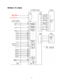
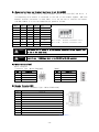
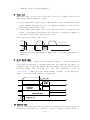
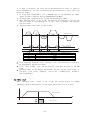
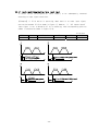
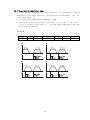
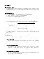
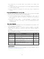
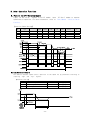
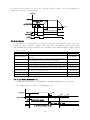
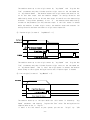
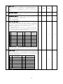
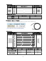
All drive I/O signals are insulated by a photocoupler. The signals display the
internal photocoupler status - [ON: Conduction] and [OFF: Non- Conduction], not the
signal voltage level.
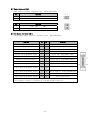
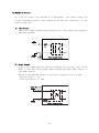
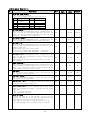
1)
Input Circuit
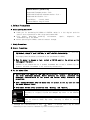
Input circuit power of DC24V±10% (consumed current : about 5mA/circuit) should be
separately prepared.
Drive Internal Circuit
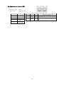
2)
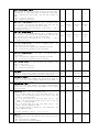
Output Circuit
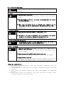
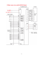
Output circuit power should be separately prepared. This may share input circuit
power. In this case, working power capacity should add output power capacity to
input power capacity.
Applied voltage and power capacity in the control output port are as follows.
·Applied voltage ≤ 30V
·Electrified current ≤ 15mA
Output Port
DC 30V
Within 15㎃
Drive Internal Circuit
- 22 -