1
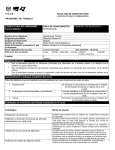
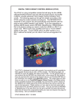
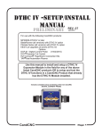
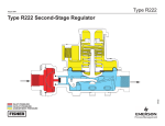
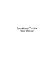
REV 0.5
PN200 Hand Control for
MACH3 based systems
PN200
TOTAL CONTROL from the PALM OF ONE HAND!
CandCNC
E-STOP
PN200
CNC HAND
CONTROL
JOG
AXIS
COM
THC ON/OFF
ZERO
REF
Step
Inc
PUSH
X
Y
Z
A
B
Z
UP
Y+
IN
YOUT
2
3
CREASE
IN
MACRO TOUCH
OFF
M
1
INTER
LOAD
LOCK Material
DTHC PRESET
-
4
SCREEN REF XY
PUSH to RESET
CREASE
IN
SPACE
7
EXECUTE
ENTER
STOP
ENTER DELETE
FEED
RATE
Single
Step
F
X+
OUT
Z
XDWN IN
5
JOG
SPEED
5.757"
OK
6
OUTPUT OUTPUT
3
2
8
9
G
TORCH/
SPINDLE
.
TOGGLE
RUN/
PAUSE
0
MODE RESET
STAY AWAY FROM MOVING MACHINERY
3.602"
DISCLAIMER: THIS MANUAL IS NOT COMPLETE AND HAS NOT BEEN PROOFED:
A LATER REVISION WILL BE RELEASED WITH ADDED INFORMATION AND CORRECTIONS
....Please check the CandCNC website (Manuals Page) for updates
to this manual. We will also post any new Macros and new software.
Page1
COM LED. Shows RS485
communication with host.
ON = Active
Single Step Option. Puts Jog mode in single
step on all axis. Flashes LED
360 Degs of Jog Control
90 Stored Macros
80 + Functions
29 buttons
6 indicators (3 dual color)
3 Direct Run Macros
3 Modes
2 Rotary Encoders
1 Analog Jogstick
STOP LED:
SOLID RED = G-Code Stop
(Code Loaded)
Flashing RED = Pause.
FEED RATE OVERRIDE ROTARY ENCODER
Increases/Decreases Feedrate with rotation. Push on
top to switch To reset Feedrate Overide to 0 (normal
commanded Feedrate. CLICK DETENT
Single Button Macros:
Load Material (Move)
TOUCH OFF (Torch)
MACRO CALL BUTTON; Allows calling stored macros
using number keypad. ENTER executes the Macro (5
sec timeout)
DTHC ROTARY ENCODER (Plasma Cutting)
Increases/Decreases PRESET VOLTS one volt per
detent. Push on top to switch for Enable/Disable THC
functions. Push & Hold for using with OXY-FUEL. LED
on SOLID for THC active. OFF for THC OFF. FLASHING
for Z manual (no THC) CLICK DETENT
Page 2
4
STOP
7
XIN
6
0
RUN/
PAUSE
8
3
.
TORCH/
SPINDLE
G
X+
OUT
F
MODE RESET
9
2
OUTPUT OUTPUT
5
Z
DWN
3
YOUT
B
JOG
SPEED
STAY AWAY FROM MOVING MACHINERY
ENTER DELETE
ENTER
SPACE
SCREEN REF XY
-
1
INTER
LOAD
LOCK Material
M
2
Y+
IN
Z
UP
MACRO TOUCH
OFF
A
Z
Y
X
Single
Step
Step
Inc
REF
ZERO
JOG
AXIS
E-STOP
Number Keypad. 0 - 9, SPACE, • , –,
XYZABFGM for MDI G-code entry. ENTER
executes a typed in G-Code line (MDI)
FEED
RATE
PUSH to RESET
CREASE
IN
DTHC PRESET
CREASE
IN
PUSH
THC ON/OFF
CNC HAND
CONTROL
PN200
CandCNC
MODE KEY. Switches keyboard function from SETUP
to PROGRAM mode. LED changes color and state:
SOLID GREEN = Setup Mode
FLASHING GREEN =PROG
OFF = Run Mode
FLASHING RED = Reset
RESET KEY: Brings MACH IN and
OUT of RESET
PROGRAM RUN GROUP. Provides control of
program run. STOP (stops program) Run/Rause
(toggle) RESET (shutdown ).
OUTPUT Control Group. Turns on Output1;
Output2 and Ouput3. Requires INTERLOCK be
depressed to turn any output ON
Keypad Jog Group. Fixed rate jog in single
direction set by JOG SPEED. When in Single
Step one step per push. Holding button down
starts 5 steps per sec.
STEP INC Button. Sets set increment in .1 .01
and .001 increments JOG AXIS LED flashes
Fast, Med, Slow
JOG SPEED LED indicator. Color and state
shows current Jog rate: Flashing Green =
10%
Solid Green = 25% Flashing Red = 50% Solid
Red = 100%
JOG AXIS LED shows axis pair
selected for Jogstick (XY or ZA)
POSITIVE EMERGENCY STOP. Hardwired
to system E-stop. Pendant must be
plugged in for release
° Proportional Jog Stick. Allows motion
in two axis. Direction is based on jogstick
direction. Speed is from 10% to 100% of
selected JOG SPEED based on deflection.
PN200 FEATURES LIST
Control virtually every aspect of your MACH based CNC machine from the palm of your hand!
?Lightweight . Easy to hold, easy to carry, easy to store. Hangs with Velcro
?Rugged, All Solid State. High Impact Plastic case. Sealed keyboard.
?Matching Screen Files with Giant DRO’s and LED’s. Visible from 20 ft; Stand back and
CONTROL!
?Single, small, flexible, UTP CAT5 network cable. Can be used up to 100ft from PC
?USB Connection at PC (requires optional USB to RS485 Adapter). Plug-n-Play installer.
?
?360° Proportional Jog stick. Jog axis Pairs XY or by clicking top switch, ZA
?Jog Axis Designators and directions defined in USER SETUP (plug-in). Jog axis can be
changed
?Keypad Jog (Axis definitions in USER SETUP).
?Single Handed Operation.
?Rotary Encoders (spinners) for setting Feedrate and changing DTHC or Spindle Speed
Settings
?4 Selectable Jog Speeds/Ranges. Applies to both Jogstick and Keypad
?Single Step Select (via keypad or jogstick)
?Step Increment Select (for precise setup or touch off. Move in .1 , .01 or .001 increments
?Hold jog key down for step repeat.
?3 preset Macros (single button macros)
?Up to 99 Stored Macros. Recall and execute from keypad.
?Easy to See Multicolor Status LED’s
?Program Mode allows entry and execution of single line common G-Code (MDI)
?Large Emergency Stop Button is hardwired and NC. Safety shutdown if PN200 is
Uses RS485 Communication. High Speed, industrial low-noise. Status LED com line is
active
unplugged.
Page 3
INSTALLATION AND SETUP
There are several steps to installing and setting up your PN200 for proper opertaion. In
the following pages we will guide you through the following steps
? Inventory and check of components.
? Running the Auto Install file from the CD
? Attaching the USB-485 Module to your MACH3 Control PC
? Checking the communications between the PN200 and the PC
? Changing the screen set in MACH
? Checking the PN200 for proper operation
? Discovery of PN200 features
? Using and Running Macros from the PN200
? Hooking Up the E-STOP Button
PN200 + USB-485 Combo System
The PN200 uses Industrial RS485 Serial Communications that are extremely reliable and noise
immune. Differential signaling and proper impendence matching, allows long runs of
unshielded twisted pair (UTP) cable to be used for communication, and allows for small flexible
cables. Since PC’s do not ship with an RS485 communications port, and expansion cards for
that purpose are expensive and hard to find, CandCNC developed our own USB to RS485
communications module. The USB-485 allows any PC with a Standard USB type 2 port to be
used. NOTE: Your MACH3 Control PC may need other types of communication ports to
function with the Motor and advanced features. This USB solution is for use with the
The
USB-485 is placed close to the PC (5 ft interface cable included). It is recommended the USB485 to PC cable NOT be longer than 6ft and NOT be extended beyond that. USB is not noise
immune and not as robust a protocol as RS485 for reliable communications. The PN200 was
developed to be a hand Control that the operator can count on to respond and do the functions
selected. Safety and reliability in a control are important. For controls that must operate in the
harsh conditions of a shop and not subject the operator or the machine to possible out-ofcontrol situations, the wireless approach was not considered.
PN200 only and provides no other interface (at this time) for other system devices.
Page 4
PN200 Combo Kit as shown ships with:
? 1ea PN200 Hand Remote Control
? 1ea
? 1ea
? 1ea
? 1ea
? 1ea
USB-485 USB to RS485 Communications Module
USB A to USB B 5ft Cable (PC to USB-485 module connection)
CAT5 UTP cable (25ft) PN200 to USB-485 connection)*
9 to 12VDC wallplug power adapter (120VAC operation only)
Installation and Support CD
Page 5
Running the Auto Install from the CD:
1. Place the CD in the CD slot of the PC you wish to use as the MACH3 Control
PC.
If your Control PC does not have a CD reader or do not have the install CD then use
a computer with internet access to go to the following website
http://www.CandCNC.com/manuals.htm
navigate to the bottom of the page to the ZIP files and find the PN200 Installer file.
Download the file and use WINZIP or XP unzip to extract the compressed file to a
Memory Stick (or local folder if the PC is networked to the Control PC). The install
MUST be run at the PC running MACH that controls your CNC machine.
2. In Windows use the File Explorer or START/My Computer to navigate to the CD.
3. You will see a file structure of several folders. One will be the manual. There will
be another named AUTO-INSTALL
4. If you do not have the manual open to do the install please open the manual prior
to starting the install
Page 6
The next screen is pre-install information. Please take a couple of minutes
to read through the text. Please note the line that says that the install is
for XP (all versions) ONLY. The install and the PN200 HAVE NOT BEEN
TESTED on WINDOWS 7. We cannot support the PN200 or this install on
WINDOWS 7. Please do not call or e-mail tech support if you are
trying to make this work on any other OS than Windows XP. You may
need to install Windows XP service Pak 2 to have the installer and or
the drivers to work properly.
The Installer will find the C:\MACH3 folder and ask you if you want to install
to that folder. Select Next and let it continue.
Page 7
The next screen confirms the install location. If you have mach installed at any other
location there will be parts of the install that will fail. The structure of MACH and it’s folders
is important and having it at any other location will cause problems in both operation and
support. Select Install. The files will be uncompressed and put in the proper structure for
MACH3. A load bar will show you the progess. The process should only take a few
seconds before the “Welcome to the CandCNC Driver Installation” pops up
You should have the USB-485 module DISCONNECTED at this time. If you have
connected the USB-485 module to a USB port Please unplug it BEFORE you hit the Next
button!
Select Next to continue with the driver install, This will Install the drivers for the USB-485
module. At the end of the install you will get the screen on the next page
Page 9
If you get the screen as shown, proceed to the next step by hitting the FINISH
button.
IF YOU HAVE A RED X next to either Driver Name OR the Status is NOT “Ready to
Use” your USB driver install has failed. You will not be able to use your PN200.
Possible failures can be from a version of XP without at least SP2 installed or from
a hardware issue with the USB ports on the PC. Select Cancel and stop the install.
Make any upgrades you need and try again. If the install fails at this point again
please contact us via e-mail ([email protected]) or on the Support Forum (Yahoo
Forum).
Page10
The post installation screen gives some directions and details on what to do
next. The actual detailed steps ARE IN THIS MANUAL and supercede any
instruction in the Install dialog box. Click Next to proceed
Page11
WHAT TO DO NEXT
After you have installed the drivers and software:
1. Plug the USB-485 wallplug to a source of 120VAC power. There is no power
light on the module, so do not be alarmed if nothing lights up. (220-240 volt power
modules are available from CandCNC or you can use any module rated at 9-12VDC at
300ma or higher)
2. Use the supplied USB cable to connect the USB-485 to an open USB jack on
your PC. As soon as you plug the USB cable in both ends you will see a small dialog
box pop up in Windows (normally lower right hand part of the screen). It will advise
“New Hardware Device Found”. IT WILL AUTOMATICALLY INSTALL THE TWO
DEVICES IT FOUND. You do not have to click or select any menu choices. If
WINDOWS does not detect the plug-n-play device then either the device is not plugged
in, not powered up (check the wallplug power pak to make sure it is firmly in a live plug)
or the PC you have does not have active USB ports. Try another USB jack.
The new device found dialog may happen anytime you plug in the USB-485 after it is
installed. It should find the device and not require a re-install of the drivers.
CHECKING to SEE if the USB-485 is properly installed
The drivers for the USB-485 are only active when the USB-485 is physically connected to a USB port
and is ON. You do not need a PN200 attached to the USB-485 to do the following checks:
1. OPEN the CONTROL PANEL on your MACH3
Control PC.
2. Select “SYSTEM” from the Control Panel
3. You will see a set of TABS.
4. Select “HARDWARE” tab
Page12
5. You will see a List (tree structure) of hardware devices on your PC.
Navigate to the Ports(COM & LPT) and expand the list by clicking on the +
next to the device(s). You should see a list of the Port devices on your PC.
There will be a “USB Serial Port” device listed with a “COM” number. You
may not have the same exact stucture as is shown below. The device driver,
when you plug in the USB-485, adds a COM port in the next available spot.
In a PC with only one COM port (COM 1) it would put itself at COM2. In
other installs it will put itself at the LAST USED COM number.
MAKE A NOTE OF THE COM number
(COM3 in the screens below) that your
USB Serial Port is attached to. You will
need that number when you do the setup
on the PN200 Plugin in MACH later in this
manual.
6. Next step is to check the Properties of the USB Serial Port and to
make sure it is the correct device.
7. Select the “Driver” tab and note that the Driver Provider is FTDI. The driver
version should the one shown OR HIGHER.
8. Once you have confirmed the driver and COM port number close the Device
Manager.
Page14
INSTALL : MACH3 Setups
In order to have the new “Big Screen” set so you can see the screen from across the room
when using the PN200, you must load the new screen sets into your MACH Profile. The
screens are in dependant of the settings and you can change them without changing the setup
or functions in the profile. NOTE: if you have custom screens you have built for your MACH
install, you can open our screen set in Screen 4 (MACH screen painter) and add the new
screens (9 and 10) and use it with your screens. You can copy entire screens and all of the
objects and any code from one SET to another. If you are an OEM (volume buyer) with custom
screens you or we have developed then contact us for help on updating your screens.
Loading the new Screens from CandCNC
1. The install program loaded a new screen set that is currently for plasma (router will follow
shortly) but your running profile still is pointed to your previous screen set.
2. Open your current running profile of MACH
3. On the top menu bar find the VIEW button
4. Click on Load Screens
Page15
5. If the Explorer window is not on the MACH3 main folder use the “Look In”
bar to navigate to the MACH folder. Scroll in the MACH3 folder until you find
the MP3000-DTHC-ESP-PN200.set file highlighted above.
6. Once it is highlighted hit the OPEN button and MACH will load the new
screen set (it may take a couple of seconds). If you are running the current
MP3000-DTHC-ESP-DCP set the front page will not change.
Page16
Here are the two new screen pages that get added. They are accessible using the
SCREEN button on the PN200 or the when you move to Program Mode on the PN200
Oversized Program Run Screen
Oversized Program Mode (G-code input) Screen.
Page17
FINAL INSTALL : MACH3 Setups
1. Once you have the USB-485 module installed, you have confirmed the drivers
are install correctly , you know the correct COM number and , the screen files
updated, Start MACH3 (if it is not already running) and Load the MACH3 Profile you
normally use. If you use more than one you will need to do the check, load screens
and settings on EACH PROFILE.
2. Use the Upper Toolbar and select the “Config” menus option. From the Drop
Down List Box select the “Config Plugins” menus option
Page18
3. You will see a Menu window similar to the one above. Make sure the
ccc_rs485 plugin is listed.
4, The Enabled column for the ccc_rs485 will probably be set off (RED X).
Click on the RED X and it will change to a GREEN Check.
5. Before you click “OK” open the CONFIG dialog for the ccc_rs485 by
clicking on the yellow CONFIG bar on the same line(row).
Proceed to step 6 next page
Page19
6. Check the COM port
number in the PN200
Setup window. It MUST
be set to the proper COM
port your USB-485 is
using. You have that
number (right?) from the
previous install steps. Put
it in now. Do not worry at
this point about the other
option tab. Click OK and
let it save the setup
IMPORTANT INFORMATION:
Anytime you make changes to a MACH3 setting it is only saved in the Profile
(XML) when you exit (shutdown normally)MACH3. Some settings take effect
immediately. A CHANGE IN A PLUG_IN DOES NOT TAKE EFFECT UNTIL YOU
STOP AND RESTART MACH3. AFTER YOU MAKE THE CHANGES TO THE
PLUG-IN L:ISTED, STOP MACH (End Session - Yes) and Restart MACH with the
same Profile.
7. Plug the PN200 into the Indicated Jack on the USB-485 module (marked for the
PN200). Use the 25 ft CAT 5 cable suppled. YOU CAN USE A LONGER OR
SHORTER CABLE BUT IT MUST BE A STANDARD NETWORK CABLE NOT A
“Crossover” cable. DO NOT try to splice on a cable or use an extension plug (femalefemale jack) USE a single cable. DO NOT USE FLAT SATIN CABLE or intercom wire.
It MUST BE UTP (Unshielded Twisted Pair) cable rated for network use. CAT 5 or
better is recommended
8. As soon as you plug the PN200 into the USB-495 module it gets power. As soon as
it gets power the internal circuits “initialize”. When they do so they will FLASH ALL OF
THE LED’s ONCE (three times on later models). Look for this as an indicator that the
unit has power and the unit is initialized
Page 20
9 IF YOUR PLUG-IN is Enabled and you have selected the correct COM Port
in the steps prior to this the PN200 should light up with several LED’s on. In
Most cases the MODE/RESET LED will be flashing RED. Other normal
indications are noted below:
Shows GREEN for
Normal XY plane
Jog Pair
COM OK LED is
ON GREEN
Jog Speed RED
Other LED’s may be
OFF or ON based on
the current settings
in MACH
MODE/RESET LED
will be flashing RED
if MACH is in RESET
NORMAL INDICATORS ON PLUGGING IN the PN200 if the
Driver is active and the COM port is installed and set correctly
Page 21
USING THE PN200 WITH
A CandCNC Controller
Page 22
SETTING MACH3 internal variables for the PN200
Setting the Jog increment in the MACH Configuration
There are several MACH3 settings that need to have the proper values in order for
the PN200 to function as it should. The first is the Jog Increment setting. It is found
in the MACH screens at CONFIG/GENERAL CONFIG.
NOTE: Only the FIRST THREE settings are used to cycle through with the PN200.
The default settings are 1, .1 and 01. Those need to be changed to .1, .01, and .001
for the first three. When the PN200 is put into single step mode then the Jog
Increment is selected using the Step Inc key. The LED above the Single Step key
will indicate which of the three Jog increments is the current setting.
While the rest of the Jog Increment settings effect the jog increment if
you are in single step mode at the console and cycle through they have
no effect on the three jog increments used by the PN200.
Page 23
SETTING MACH3 internal variables for the PN200
Setting the LOAD MATERIAL POSITION in the MACH Screens
The following setting is located in the custom screens provided by CandCNC with all of our
products. If you are using another screen set you will not have this tab and will not have the
Load Material option. In that case you will not be able to use the Load Material single button
Macro. See the Using and Programming Macros section to be able to use preset values
in a macro. It’s not as clean as having values you just input from MACH but it works.
For users with the CandCNC screen set open the SETTINGS TAB and in the right hand part
of the screen you will see 4 blue DRO’s that hold the settings for load material. In order to
enter and change a value (in ANY MACH DRO) you first click on the DRO (will turn the
background another color and type in the value you want. YOU MUST HIT ENTER for the
value to actually be stored. In the Load Material DRO’s put the values for each axis. You
cannot have zero in any of the three axis (XYZ) locations or the macro will not run. There is
a detailed breakdown of this specific Macro in the Using and Programming Macros
section of this manual.
Setting the Touch-off Switch offset value in MACH
Starting with the PN200 screen sets we have
added a place to input the Switch Offset value
in MACH. This is used with the “Touch Off “
Macro on the PN200. It is the exact same
number you use with the DTHC programmed
into the SheetCAM post (see the DTHC or
DTHCII manuals for details on determining and
setting the SwitchOffset variable in SheetCAM
or in the Home offsets in MACH (BUT NOT
BOTH!). At this point the value in the Settings
Tab is ONLY used with the PN200 and the
Touch-off macro and the value must be > 0.
Later we will make available a new Post for
Sheetcam that can call the macro rather than
use the internal value.
Put in your
Switch Offset
value for your
FloatingTorch
Holder here
Page 24
Using and Programming Macros for MACH3
INTRODUCTION
Writing macros can be complex and is the subject of numerous manuals, internet
forums. For more detailed information a good place to start is the MACH Forum at
http://www.machsupport.com/forum/index.php. The macro language in MACH is
based on a subset of VBScript. There are internal MACH functions and variables
that can be accessed to interact with the script. The scripts and get or put vaules
in screen DRO’s (Digital ReadOuts) activate buttons, read the state of inputs and
activate and deactivate outputs. Another powerful feature is to run g-code and to
use common logic processes in VB like the IF..THEN...ELSE and DO WHILE.
Standard math functions are available.
Macro language is in basic text and can be built with nothing more complex than
a simple text editor. MACH contains a VB editor and there are several editors that
make the process easier to read. While the script must use the correct syntax’
formatting is less stringent. Most programmers use formats like indents and
comments to make the code easier to read and understand. While VB code can
get complex and have thousands of lines of code, most single purpose MACH
scripts are scripts are less than a hundred lines.
It is not the intent of this manual to teach the user how to write complex macros
but tp introduce the reader to the concept of MACROs and to cover how the
PN200 can access and use a wide variety of macros.
It is important to understand that each MACH Profile has it’s own set of Macros.
In MACH the structure looks like that shown below. Note that in the MACROS
subfolder the are folders each named the same as the Profile. This structure is
created when you use the MACH Loader to COPY a profile. The macros
associated with each profile are in that profiles macro folder.
This structure is from
our PC running
MACH and the
PN200 but your
structure may be
somewhat different
with different macro
folder names.
NOTE: The Auto - Install file for the
PN200 adds the M1000-M1009
series macros to ALL macro
folders. It does that using a simple
Batch file. New macros when
released will be available as single
files that will need to be copied to
every profile macro you will use
them in. There will be a master
macro installer folder and it will
contain all of the current released
macros in the M1001 to M1025
range and will install (overwrite) all
of the macros of those numbers in
ALL of the macro folders,
Page 25
Shown is a typical file structure inside one of the
named macro folders. Several of the files are
“default” put there by MACH when the profile is
created. It is STRONGLY advise not to edit, modify
or mess with any of the named macros or any macro
numbered below M100. The Hiddenscript.m1s is
actually part of the screen script associated with the
specific profile and should never be opened with
anything external to the VB Scripting app for working
with the Edit Buttons in the MACH application.
Note the macro numbers are M1000 and above. The
PN200 uses those exclusively for both single button
and user defined macros. IT IS ADVISED TO NOT
USE OR EDIT M1001 through M1025. Marcos in the
M1001 to M1009 are reserved for the “Single Button”
macros on the keypad. Presently there are only three
single button macros available (M1001; M1004 and
M1007. If you make changes to the any of the three
listed macros you effect what the macro does direct
from the keypad. New Macros to be released will be
numbered in the span from M1010 to M1025. If you
wish to program your own macros, or use ones from
another source, first test the macro in MACH and run
it in the VB editor to assure it does exactly what you
want then use a number above M1025. That will
prevent having to move or re-number any macro we
will release in the future
HOW TO CALL A MACRO WITH
THE PN200 HAND CONTROL
The Single Button Macros are called and executed directly
using the labeled buttons on the Keypad. They are in the M1001
to M1009 range and are numbered to match the numbers on the
keys. To call the TOUCH OFF macro (M1001) you simply push
that key anytime the PN200 is active and not in RUN Mode.
To run a custom stored macro you must know the last two digits of the macro.
EXAMPLE: To call a macro numbered M1022 you would just need to remember the ‘22 part of the
number. To run that macro you would:
1. Hit the “MACRO” button and follow that with the number button 2 twice.
2. You then have 5 seconds to hit the ENTER button (lower left) to EXECUTE the macro, If you
wait beyond the 5 seconds the input is cancelled.
Page 26
M1001 MACRO WITH COMMENTS
' strings beginning with a single quote character and not closed are comments and are ignored by the code engine during processing.
' each line of a comment must start with a single quote character
' they can help clearify the code and let you remember months or years later what you did!
' spaces, tabs and indents are ignored by the code engine
' this macro performs the touch off operation and uses a value from the CandCNC screen set.
' warning spelling is important. A variable with another name is treated as a new variable and will return a 0
Dim Switchoffset 'declare a variable
Switchoffset = GetOemDRO(1045) ' set the variable equal the the value we get from the Touch Off Swtich value
' the number of the DRO (1045) is defined when it is created in the Screen Painter
If Switchoffset > 0 Then ' condtional statement that allows execution IF the value is greater than 0
While ismoving()
' creates a loop that executes as long as there is movement. The code needs time for the operation to complete
Code "G28.1 Z.500"
' this is a standard MACH g-code that tells Z to move to the home switch and to slowdown starting at .5 "
' it will stop when the switch is made and backoff slightly and stop. Lines to run are enclosed in double quotes
Code "G92 Z 0.000"
' resets the Z DRO to 0 to get a new starting point
Code "G00 Z " & Switchoffset 'raises the Z up the switchoffset value. that should be with it setting just at the top of the material
Code "G92 Z 0.000"
' Resets the Z DRO again so the top of the material is now Z 0
Wend
' ends the loop
Else
' do this if the Switchoffset is 0 (first condition was false)
MsgBox("Your Switch Offset value in MACH needs to be set")' put a message box on the screen to warn the operator.
' requires input to proceed
End If ' ends the IF statement.
Using the internal MACH VB Script Editor
In the MACH Top Tool Bar find the OPERATOR and scroll to the VB
SCRIPT EDITOR
Page 27
VB Scripter Window
Each button function will show in the lower left corner when you move over it
with the cursor.
Finding the script to work on
Page 28
Navigate to the subfolder in the MACH/MACROS folder you want to open
M1001 Script is selected and appears with the comments in the window
From the code window
There is a mistake in this code, can you find it? (see the next page to see the tested code)
Tested code without comments.
You can test a macro by using the step button (green arrow + double vert bars), If you get a
compile error there is a problem with the code; usually caused by forgetting a quote or failing to
place the END IF at the end of an IF statement.
Using the single step mode, you can actually run the code in MACH, BUT you MUST have Mach
on the screen with the VB Script Editor, AND have MACH out of RESET. Also be aware that if
MACH is looking for a feedback (like the home switch in the code above) it will need to get the
signal from MACH. If you are running in simulation (no hardware attached) then you have to
setup MACH with key emulation (in this case Z home input) and you have to change the window
focus to Mach and hit the key to emulate the Z switch. You have to change back to the VB Scipt
window to step to the next line in the code. It’s a hassle sometimes, but you can get a good idea
of what the macro will do BEFORE you let it move your expensive CNC toy!
Page 30
USING THE PROGRAM MODE ON THE PN200
The PN200 allows the operator to enter a single line of G-code from the keypad and
execute that line. The PN200 needs to be put into a Special Program Mode by
pressing and releasing the MODE button. The MODE LED will flash GREEN when
it goes into program mode and the screen will automatically switch to the BIG
Program Mode screen on the Monitor. You will be able to see the Code as you type
it in and if it generates an error it will display on the screen. When you are in
program mode the button functions are represented on the lower (green) part of the
key
CODE SHOWS UP HERE AS IT IS ENTERED
Using the Program mode you can move an axis to a specific postion and run most valid
G-code. Not supported are the IJ commands or any specail codes like ‘O” or L codes.
When you are finished running in Program mode you can swtich back to Setup mode by
hitting the MODE button again. The screen may need be switched back the Program
Run (big) screen or the normal Program Run Screen. You can do that by hitting the
SCREEN button once to go back the the BIG Program Run and again if you want to
toggle back to the normal Program Run screen.
Page 31
Hooking up the E-STOP BUTTON to CandCNC hardware
Provisions have been made in the PN200 to provide a “hard” E-STOP (meaning it does not
rely on software or signaling of any kind to be able to put a system in E-stop). In all
CandCNC systems there are at least one software level E-stop (stops MACH from sending
pulses). In our Plug-n-Run systems there is also a hardware E-Stop that shuts down power
to the motors (and trips the software (EPO) shutdown as well). The following pages show
how to use the PN200 with both types of systems. If you have a controller from another
vendor or built by someone other than CandCNC most will have at least a way to do an estop.
The E-STOP button on the PN200 is a
NORMALLY CLOSED (NC) momentary
pushbutton. The two switch contacts go back
through two dedicated wires on the CAT 5 cable
to the USB-485 module. When connected to an
e-stop system that uses swiches it that all of the
switches MUST be CLOSED in order for the
system to run. The PN200 becomes one of the
series switches. Added safety is built in since all
of the switches MUST be in the circuit and not
active, so a disconnected wire, an open run or
defective connection, will stop the system.
Once connected in a NC type E-Stop system,
the PN200 becomes one of the NC elements.
Pushing the button opens the circuit.
Disconnecting the PN200 either by choice or by
accident will E-STOP the system.
The following pages will show how the PN200
can be connected to a system with a software
(MACH input) E-STOP using the CandCNC
Table I/O card as an example. Another option
is to have the E-STOP circuit actually shutdown
power to the drives and motors and issue a
software E-STOP to the MACH input. All
CandCNC Power Controllers (SPSC / EPS
/ESPII) have a prevision to tie in a Normally
Closed switch at the power controller and stop
motion instantly. While Stepper systems can be
stopped simply by removing the step signal from
the drives, Servo systems can continue to move
and run as long as power is on if the software
loses control of the motor drives. Several
conditions can result in a servo “runway” where
the only cure is to shut off power to the drives. If
you have a servo system (or just want to have
the ABSOLUTE E-stop options there are
instructions on the following pages to
accomplish that with a CandCNC controller
Page 32
WHAT TO DO IF YOU ALREADY HAVE ONE OR MORE NC SWITCES in your E-STOP
circuit:
1. Treat the output of the USB495 E-STOP as another normally close swtich.
2. Break one end of the string and insert one wire from the USB485 E-Stop you have
hooked up onto each end of the break.
3 Plug in the PN200 and make sure you can come out of RESET.
4. Test to make sure the E-STOP on the PN200 works and that unplugging the PN200
will force MACH into RESET.
SERIES CONNECTED
multiple E-STOP switches
NO COM NC
NO COM NC
Normally tied to T20
Normally tied to T21
Terminal numbers are for
CandCNC Table I/O card
SERIES CONNECTED
multiple E-STOP switches
NO COM NC
NO COM NC
Normally tied to T20
Terminal numbers are for
CandCNC Table I/O card
Normally tied to T21
+9 to +14VDC
COM NC
UTP
Cables
RS485
Device1
PN200
USB A -B
CABLE
TO PC
RS485
Device
2
REV 1
CandCNC Part# USB-485
DC PWR IN
USB to RS485
E-STOP
To use multiple E-Stop switches including the one on the
PN200 connect existing E-STOP string of NC swtiches as
shown. While the connections are shown for a CandCNC
Table I/O card it will work for any setup where Normally
closed switches are use in the E-STOP circuit.
Page 33
Using the PN200 with a software only (MACH) e-stop system.
DC PWR IN
CandCNC Part# USB-485
RS485
Device
2
RS485
Device1
PN200
UTP
Cables
E_STOP Crossconnect
To E-stop terminals on BoB
or control
E-STOP
REV 1
Use stranded insulated wires #22 up to #18. Any color. No
Polarity is needed. Put one wire in T20 and one on T21 of the
Table I/O card
REMOVE EPO JUMPER to use with
PN200 E-STOP
T17
T3
UP
T4
EPO
T11
ARC OK
J1
C14
K5
D15
BHOME
AUX1
K3
D3
K4
J13
R1
AUX2
J12
K4
R2
J18
J5
AUX3
C11
NO Com2
Com1
48
NO
J7
J8
AUX4
J11
DANGER!
DANGER!
J4
C10
Xhome
YHome
K3
D2
10
13
25
C&CNC
TABLE
I/O
47
REV 6
J6
T13
K4
C13C12
QUAD RELAY
J33
C1
6
1
J10
T15
ZHome
AHome
LIMITS
UP
DWN
AUX0
1
14
J9
T12
C2
T10
AUX0
DOWN
T2
T19
T20
T21
T14
ARC OK
LIMITS
AHome
C9
T16
C4
C3
T18
ZHome
T6
YHome
T5
52
T7
C5
T8
C8
PLUG
C7
C6
J2
T9
Xhome
USB A -B
CABLE
TO PC
USB to RS485
+9 to +14VDC
COM NC
Most BoB’s provide for an input for E-STOP into MACH. You can define that input to
work with either Normally Open or Normally Closed contacts (but not BOTH). The
recommended approach for safety and reliability is to connect the switches in series (like
the old strings of Christmas lights) so if one goes out they all go out. Then the beginning
and end of the string is tied to one input.
CandCNC Table I/O card. Standard card sold with
BladeRunners, Builders Paks, Plazpaks and Router Paks
This card located inside on BladeRunner Units behind UBOB III
card in the top of the enclosure.
Page 34
“ABSOLUTE” E_STOP. Shuts down motion instantly and sends E-stop
to MACH. Recommended for all servo based systems.
USB A -B
CABLE
TO PC
UACM FRONT (Smart Panel) Card has a set (2) of
RED OFF BUTTON ON THE FRONT OF THE
ESPII BOX BUT CAN BE MOUNTED AT THE
RS485
Device1
PN200
The USB-485 can be wired into the screw
terminals. If your ESPII based unit has a wire
jumper between the two screw terminals
remove it and replace with the two wires from
the USB-485 module. If you have an existing
external E-stop then you must place the
USB-485 in series with the other switch (or
series string of switches)
REV 1
UTP
Cables
TABLE.
CandCNC Part# USB-485
RS485
Device
2
switch can be tied in and mounted External
to the cabinet. It does the same thing as the
USB to RS485
screw terminals where a remote shutoff/panic
DC PWR IN
E-STOP
+9 to +14VDC
COM NC
If USB-485 is mounted more than 6
ft from Front Panel card use twisted pair
wire. 24 to 20 ga wire is okay.
Back Side of UACM Smart Panel Card
On all ESPII Power Controllers
Serial to UBOB
D19
J3
NC C NO
LS2
J29
J9
BladeRunner
ONLY
1
Interface
+
D5
To External DB9
on MTA Side Plate
2
1
EPO
Jumper
to RUN
EPO
G251-4
DB9 Serial
Q6
2
UACM
16
15
J45
ESP 650
& 1500
ONLY
2
1
4
2
STOP
SW2
MTA
1
1
4
6
7
8
Test
1
J1
SW3
TEMP2 KILL
Drives
Off
Power
Fault
RUN 3
Y1
U7
CandCNC
UACM
FRONTPANEL
REV3
4
2
1
3
5
2
SW1
TEMP PROBE
C
Test
1 J52
1
J4
MODE
3
J63
1
SIP6
1
20
19
Temp
Fault
Lamps & Switches
on Backside of card
+5 OK
Drive
Fault
This card located in front panel of all BladeRunner AIO Dragon -Cut and later
models of all Plazpak and RouterPak units with ESPII contorller
Page 35