1
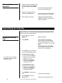
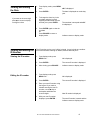
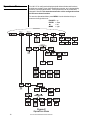
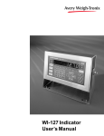
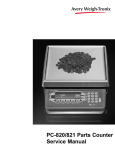
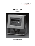
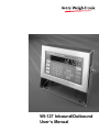
WI-127 Inbound/Outbound
User’s Manual
EUROPEAN COUNTRIES
WARNING
This is a Class A product. In a domestic environment this product may cause radio
interference in which the user may be required to take adequate measures.
CAUTION
Risk of electrical shock. Do not remove cover. No user serviceable parts inside. Refer servicing to qualified service personnel.
Weigh-Tronix reserves the right to change
specifications at any time.
July 2008 127io_u.P65 PN 29674-0012 Issue AJ Printed in USA
2
WI-127 Inbound/Outbound User’s Manual
Table of Contents
Table of Contents .............................................................................................................. 3
Specifications .................................................................................................................... 4
Introduction ....................................................................................................................... 5
Operations Mode ............................................................................................................... 5
Front Panel ........................................................................................................................ 6
Keys ............................................................................................................................ 6
Standard Scale Keys ............................................................................................ 6
Function Keys ....................................................................................................... 7
Keypad Keys ........................................................................................................ 7
Directional Keys ................................................................................................... 7
Annunciators ............................................................................................................... 7
Gross Weighing ................................................................................................................ 8
Method 1: Inbound/Outbund Weighing .............................................................................. 8
Capturing an Inbound or Outbound Weight ................................................................. 8
Inbound/Outbound Shortcut ........................................................................................ 9
Printing a Report ......................................................................................................... 9
Editing and Deleting Channels .................................................................................... 9
Method 2: Multiple Tare Registers ................................................................................... 10
Defining Tare Registers ............................................................................................ 10
Creating New Registers or Accessing Existing Registers ................................... 10
Entering and/or Editing Tare Register Values ..................................................... 10
Clearing/Deactivating Tare Register Values ....................................................... 11
Editing and Deleting Tare Registers.......................................................................... 11
Net Weighing ............................................................................................................ 11
Printing a Report ....................................................................................................... 11
Using Cutoff Registers .................................................................................................... 12
Viewing Cutoffs ......................................................................................................... 12
Entering Cutoff Values .............................................................................................. 12
Clearing/Deactivating Cutoff Values ......................................................................... 12
Checkweighing ................................................................................................................ 13
Setting Target and Over/Under Values ..................................................................... 13
Checkweighing Operation ......................................................................................... 14
Customizing the Indicator ................................................................................................ 14
Viewing and Setting Time ......................................................................................... 14
Viewing and Setting Date .......................................................................................... 15
Viewing and Editing the ID Number .......................................................................... 15
Operations Menu ...................................................................................................... 16
Description of Operations Menu ......................................................................... 17
Serial Communication ..................................................................................................... 18
Inbound/Outbound Printouts ..................................................................................... 18
Tare Register Printouts ............................................................................................. 19
Error Messages ............................................................................................................... 20
Indicator Diagnostics ....................................................................................................... 21
Test Mode ................................................................................................................. 21
Pages are numbered consecutively beginning with the cover page.
WI-127 Inbound/Outbound User’s Manual
3
Specifications
Power requirements:
115 Volts AC, +10% to -15% @ 0.3Amp maximum
230 Volts AC, +10% to -15% @ 0.15 AMP maximum
50 /60 Hz
Excitation: 10 Volts DC
Supports up to twelve 350-ohm weight sensors
Operational keys:
Five yellow standard keys: Zero, Tare, Print, Units,
Select
Three function keys: INBOUND/OUTBOUND, TARE
REGISTER, CUTOFF
Numeric keys: 0-9
Operational annunciators:
Gross, Tare, Net, Print, Zero, Motion
Under, Accept, Over, Cutoff, ID,
Three units of measure
Display: Eight digit, seven segment, 0. 8-inch high LED
Display rate: Selectable (1, 2, 5, 10)
Analog to digital conversion rate: 60 times per
second
Unit of measure:
Three, independently programmable:
Pounds, kilograms, grams, ounces, ton, tonne,
custom, Off
Standard outputs:
Three outputs, open collector design
Relay power supply, 24 VDC at 150mA
Bi-directional serial port (RS-232 or RS-422/485 or
20mA current loop)
Self diagnostics:
Display, keys, inputs, outputs, serial port,
A to D converter, loadcell output display, voltages
Circuitry protection: RFI, EMI, and ESD protection
Options:
Two additional serial ports
BCD parallel
10 cutoffs
Analog output
0-5, 0-10 volts
1-5, 4-20, 10-50 mA
Operating temperature:
-40 to 140° F (-40 to 60° C)
100% relative humidity including washdown
Enclosure: NEMA 4X stainless steel enclosure
Dimensions:
12" W x 8" H x 4" D (without mounting bracket)
12.3" W x 11.0" H x 5.3" D (with mounting bracket)
Weight: 12.5 lb, 5.7 kg
Capacity selections:
999,999 with decimal located from zero to five places
Incremental selections:
Multiples and sub-multiples of 1, 2, 5
Programmable selections:
Zero range, motion detection,
automatic zero tracking, five-point linearization.
Time and date /RAM:
Battery backed up real time clock and RAM are
standard
Internal resolution: 6,291,456 counts per mV/V per
sec.
HarmonizerTM digital filtering:
Fully programmable to ignore noise and vibration
Standard inputs:
Seven logic level inputs for functions such as tare,
print, zero, units, select, gross and net.
4
WI-127 Inbound/Outbound User’s Manual
Introduction
The WI-127 Inbound/Outbound is a microprocessor-driven weight indicator
designed to interface with an electronic scale. Its purpose is to calculate net
weight value and to transmit serially that value, along with other weighing
information, to a printer, computer, or programmable controller.
A hallmark of the WI-127 Inbound/Outbound indicator is its versatility in
adapting to a broad range of weighing applications requiring calculation of
net value.
Two methods of net weighing are available:
Method 1: Inbound/Outbound Weighing allows you to live-weigh an empty
or full container (or vehicle, etc.), with or without transmission of
data. Later you may live-weigh the same container for calculation of a net value and transmission of data. The indicator will
select the larger weight as the gross weight and always transmit
a positive net weight. The first weighing of the container stores
its value in memory so that similar weighing operations can
continue in up to 300 other channels between the time of the
first weighing operation and the second. The indicator will keep
track of the number of transactions and accumulate the totals
for each inbound/outbound channel.
Method 2: Using Multiple Tare Registers allows you to store tares in two
different ways. You may:
• Live-weigh an empty container and store its tare value in one
of 300 tare registers. Then do multiple live weighings with the
same refilled container or with containers of equal tare weight
value. The WI-127 Inbound/Outbound Indicator will use the
tare value you stored in memory for calculation of net value
and transmission of data.
• Enter using the keypad a predetermined weight value in one of
300 tare registers. Then do multiple live weighings with filled
containers equal in weight to the memory-stored value for
calculation of net value and transmission of data.
The indicator will also keep track of the number of transactions
and accumulate the totals for each tare register.
Operations Mode
Operations mode contains all normal weighing operations. In this mode you
can view or set the following parameters:
• inbound/outbound channels
• multiple tare registers
• cutoff registers
• target, over and under values
• time
• date
• identification number
WI-127 Inbound/Outbound User’s Manual
5
Front Panel
The WI-127's front panel consists of 24 keys and fourteen annunciators.
Figure 1
WI-127 Front Panel
Keys
The WI-127's keys are divided into four primary groups:
Standard Scale Keys
Standard Scale Keys These yellow keys are common to a majority of
weighing applications and include SELECT, TARE, PRINT, ZERO, and
UNITS.
6
SELECT
Used to switch between the gross, tare, and net display
modes. SELECT can also be used to accept a current
selection and return to weigh mode from within any
menu.
TARE
Enters a pushbutton tare in the display mode. Can be
configured to accept values through the numeric
keypad.
PRINT
Used to initiate manual data transmission.
ZERO
Zeros the scale in the display mode. Also clears values
in numeric entry.
UNITS
Switches the units of measure in the display mode. Up
to three units of measure are selectable.
WI-127 Inbound/Outbound User’s Manual
Function Keys
Operation of these keys
changes with the software
installed in the WI-127. (standard, in-motion, GTN)
Keypad Keys
Directional Keys
Annunciators
These oval keys, along the right side of the display face, are configurable
and are labeled INBOUND/OUTBOUND, TARE REGISTER, and CUTOFF.
The default configurations for these keys are:
INBOUND/OUTBOUND
Accesses inbound/outbound GTN weighing
function (see Method 1)
TARE REGISTER
Accesses multiple tare registers (see Method 2)
CUTOFF
Accesses cutoff registers (see Cutoff Registers)
These are the twelve square keys which support numeric entry. The keyboard keys are labelled 0-9, plus/minus (+/-), and decimal point (.) and are
located near the center of the display face.
The directional keys are used to navigate through the WI-127's menus.
These keys are labeled ESCAPE (up), ENTER (down), ← (left), and MENU
(right) and are positioned in a compass-like cluster on the display face.
These directional keys are denoted by the small transparent arrows located
next to them. ESCAPE, ENTER, and ← also support numeric entry.
ESCAPE
Exits a menu parameter without saving any changes.
ENTER
Used to end digit entry, accept a change made, or select an
item from a function list.
←
Backspaces (deletes the last digit or punctuation mark entered)
while in numeric entry and moves left within a menu.
MENU
Accesses menus and moves right within a menu.
The WI-127 has fourteen annunciators.
Gross
Illuminates when indicator is in gross weighing mode.
Tare
Illuminates when viewing tare values in the various tare
registers.
Net
Illuminates when indicator is in net weighing mode.
lb, kg, other
Illuminates the active unit of measure in weighing mode.
Print
Illuminates when the indicator is transmitting data.
Zero
Illuminates when the scale is within ±.25% of increment
center of zero.
Motion
Illuminates when the scale detects motion (within
configured motion window).
Under, Accept, Over
Illuminates relative to respective values stored.
Cutoff
Illuminates when a cutoff entry is made.
ID
Illuminates in special display mode during which inbound and outbound (net) weights are displayed.
WI-127 Inbound/Outbound User’s Manual
7
Gross Weighing
To perform gross weighing operations, follow these steps:
1. Power up the indicator.
2. Verify the scale is empty and
zero the scale by pressing the
ZERO key.
3. Select unit of measure by
pressing the UNITS button.
4. Place weight on the scale.
Indicator powers up in gross weighing mode.
Zero weight is displayed and the
zero annunciator illuminates.
The units annunciator will illuminate
next to the chosen unit of measure.
Gross weight is displayed.
Method 1: Inbound/Outbound Weighing
The inbound/outbound weighing function stores inbound weight and time
and date information in up to 300 channels. Then, when the outbound
weighment is stored, the indicator peforms an accumulation and prints the
net weight.
Capturing an inbound or
outbound weight
1. From gross weight display mode,
press INBOUND/OUTBOUND.
The INBOUND/OUTBOUND
key will work only if the indicator is in gross weighing mode.
2a. Enter a channel number using
the keypad (this will either create
a new channel or call up a
previously entered one), or
Channel numbers may be from
1 to 6 numerals in length.
2b. Use the MENU (forward) and
← (backward) keys to select a
previously entered channel . . .
If a new channel was created
or if the existing channel had
no value for the inbound
weight, the captured weight is
stored as the inbound weight.
3. With weight on the scale,
press ENTER . . .
If the channel already had an
inbound weight, the captured
weight is stored as the outbound weight and is added to
the accumulator total. After the
outbound weight is printed, the
inbound weight is cleared form
the channel.
8
WI-127 Inbound/Outbound User’s Manual
__
is displayed, prompting
for a channel number.
The channel number is displayed.
The weight is captured and the
indicator prints the transaction. At
the end of an inbound/outbound
operation, the inbound and net
weights are displayed respectively
for four seconds. The ID annunciator
illuminates during this special mode.
Inbound/outbound
shortcut
To eliminate a keystroke, use the following shortcut for capturing a weight:
1. With weight on the scale, enter
the channel number using the
keypad . . .
2. Press INBOUND/OUTBOUND.
Printing a report
Channel number is displayed.
The weight is captured and the
indicator transmits the transaction to
a peripheral printer.
This utility is accessed from the Operations Menu shown in Figure 2. You
may follow the steps below or refer to Figure 2 for a visual representation.
1. From weight display mode,
press MENU . . .
G.t.n. is displayed.
2. Press ENTER . . .
rEPOrt is displayed.
3. Press ENTER . . .
A report is printed. The default
printout is a report of the GTN
database information for each
channel.
4. To return to weight display mode,
press SELECT.
An inbound/outbound report prints:
• the time and date
• all truck numbers in the
database and their corresponding net totals
• all truck numbers that only
have an inbound weight and
their net totals.
Sample Inbound/Outbound Report
Editing and Deleting
Channels
You may delete any or all of the channels in your WI-127. To do so, you
must access the Operations Menu (Figure 2). The complete menu and
descriptions are in the "Customizing the Indicator" section. Please refer to
that section.
If your indicator is configured to allow editing of the inbound/outbound
channels, you may also: the inbound hour, the inbound date, the accumulator value, and the transaction counter.
WI-127 Inbound/Outbound User’s Manual
9
Method 2: Multiple Tare Registers
The multiple tare function provides up to 300 tare registers. Tare weights
may be entered as a live weight (pushbutton tare) or as a keypad entered
weight.
Defining Tare Registers
Creating New Registers or
Accessing Existing
Registers
Use these instructions for creating new tare registers or for accessing
previously entered registers. Up to 300 registers may be used.
1. From weight display mode,
press TARE REGISTER . . .
The current tare register number is
displayed. (If no tare registers are
present, __
is displayed, prompting you to enter a tare register
number.)
2a. If creating new registers, enter in
the register number using the
keypad, or
2b. If registers already exist, enter in
the register number using the
keypad, or use the MENU
(forward) and ← (backward)
keys to select a tare register . . .
3. Press ENTER . . .
The tare register number is displayed.
The tare value in that register is
displayed.
You are now ready to enter tare values into these registers. Follow the
instructions in the following section Entering and/or Editing Tare Register
Values.
Entering and/or Editing
Tare Register Values
Once you have accessed a tare register, you may enter new tare values or
edit existing values. Following is the standard procedure.
1. With the tare value displayed,
you can enter/edit a tare value in
a register in two ways:
a. Key in a tare value:
Key in your desired tare value
using the keypad, then press
ENTER . . .
The tare value is accepted and the
ndicator returns to net display mode.
or
b. Use the pushbutton tare:
With the tare weight on the
scale, press TARE . . .
10
WI-127 Inbound/Outbound User’s Manual
The new tare value (the weight on
the scale) is displayed and accepted.
Clearing/Deactivating
Tare Register Values
To clear a tare register value, use the keypad to set the value to zero.
Editing and Deleting
Tare Registers
Multiple tare registers in the WI-127 may be edited: you may change the tare
value, the net accumulator total, and the transaction counter. You may also
clear values from individual or multiple registers and you may delete any or
all of the tare registers.
To edit and delete tare registers, you must access the Operations Menu
(FIgure 2). The complete menu and descriptions are displayed in the section
Customizing the Indicator. Please refer to that section for editing and
deleting.
Net Weighing
You may view the current or
active tare value at any time
during a weighing process.
From gross or net weighing
mode, press SELECT until the
tare annunciator illuminates. If
a tare value is in use, it will be
displayed.
Printing a Report
To perform net weighing with a tare register, the register must already exist
and have a tare value stored in it. If you have already set up your tare
registers and are ready to perform net weighing operations, proceed to the
next section. If you still need to create your tare registers, refer to the
section Defining Tare Registers on the previous page.
1. From the weight display mode,
enter the desired tare register
number using the keypad . . .
Tare register number is displayed.
2. Press TARE REGISTER . . .
Tare value is displayed in net mode.
3. Place weight on the scale . . .
Net weight is displayed.
4. Press PRINT . . .
A printout including time, date, tare
register number, and gross, tare, &
net weights is performed.
This utility is accessed from the Operations Menu shown in Figure 2. You
may follow the steps below or refer to Figure 2 for a visual representation.
1. From weight display mode,
press MENU . . .
G.t.n. is displayed.
2. Press MENU again . . .
tArES is displayed.
3. Press ENTER . . .
rEPOrt is displayed.
4. Press ENTER again . . .
A report is printed. The default
printout is a report of the tare
database information for all active
tare registers. (See Method 2 for an
example of the default printout.)
5. To return to weight display mode,
press SELECT.
WI-127 Inbound/Outbound User’s Manual
11
Cutoff Registers
The standard WI-127 includes three cutoffs. Adding the optional cutoff card
raises this number to ten.
When activated (weight on the scale is less than the weight in the cutoff
registers), these cutoffs are all on at the same time. Each cutoff will deactivate as soon as the weight on the scale matches the value in each cutoff
register.
Cutoffs may be positive or negative values.
Viewing cutoffs
Cutoff registers may be viewed by two methods:
Method A:
1. Press the CUTOFF key. . .
1 xx is displayed. The number 1
stands for cutoff register #1 and xx
is the current value in register 1.
2. Continue pressing CUTOFF or
MENU to scroll forward or ← to
scroll backward through the
remaining cutoff registers.
Press ENTER at any time to
exit the cutoff register menu.
Entering cutoff values
Method B:
If you know which cutoff register you
wish to view, press the number of
that register, then press CUTOFF.
That particular cutoff register is
displayed. You may scroll through
the remaining registers by pressing
the CUTOFF key consecutively.
To enter a cutoff value,
1. Press CUTOFF until the cutoff
register you wish to set is
displayed.
3
0 (for example).
3
xx is displayed.
2. Enter the cutoff value in one of
two ways:
Press ENTER at any time to
exit the cutoff register menu.
2A. Key in the correct cutoff value
using the keypad . . .
or
2B. With active weight on the scale,
press TARE . . .
3. Press MENU or CUTOFF to
accept the value and move to the
next cutoff register.
4. To return to weight display mode,
press SELECT.
Clearing/deactivating
cutoff values
12
To deactivate or clear a cutoff value,
set the value to zero.
WI-127 Inbound/Outbound User’s Manual
The active weight is set as the cutoff
value.
Checkweighing
Setting Target and
Over/Under Values
The WI-127 is configured to perform checkweighing functions. The
checkweighing parameters are accessed through the Operations Menu
shown in Figure 2.
The target value must be considered when determining values to enter for
over and under. Depending on the target values, the over/under values can
be entered as either actual weight values or as tolerance values.
The ACCEPT annunciator does
not illuminate when target = 0.
If the target value is zero, you may enter over and under values as actual
weight. For example, if the target = 0, over might = 100 lbs, and under
might = 50 lbs.This means that any weight between 50 lbs and 100 lbs is
acceptable.
If the target value is a value other than zero, the over and under values must
be set as tolerances. For example, if target = 100, over might = 10, and
under might = -10. This means that any weight between 90 and 110 lbs is
acceptable.
1. Press MENU until. . .
boundS is displayed.
2. Press ENTER . . .
OVEr is displayed.
3. Press ENTER. . .
The over tolerance is displayed and
the OVER annunciator illuminates.
4. Using the keypad, enter the new
over tolerance value. . .
New value is displayed.
5. Press ENTER. . .
OVEr is displayed.
6. Press MENU. . .
UndEr is displayed.
7. Press ENTER. . .
The under tolerance is displayed
and the UNDER annunciator illuminates.
8. Enter the new under tolerance
value. . .
New value is displayed.
9. Press ENTER. . .
UndEr is displayed.
10. Press MENU. . .
tArgEt is displayed.
11. Press ENTER. . .
The target value is displayed and the
ACCEPT annunciator illuminates.
12. Enter the new target value. . .
New value is displayed.
13. Press ENTER. . .
tArgEt is redisplayed.
14. After entering all new values,
press SELECT. . .
Indicator returns to display mode.
WI-127 Inbound/Outbound User’s Manual
13
Checkweighing
Operation
1. With the indicator in display mode,
verify the scale is empty and zero
the scale by pressing the ZERO
key. . .
Zero weight is displayed and the
zero annunciator illuminates.
2. Select the unit of measure by
pressing the UNITS button. . .
3. Place weight on the scale. . .
The units annunciator will illuminate
next to the chosen unit of measure.
Weight will be displayed and the
UNDER, ACCEPT or OVER annunciator will illuminate.
Customizing the Indicator
The ID number, time, and date are accessed through the Operations Menu
shown in Figure 2. You may follow the instructions in this section or refer to
Figure 2 for a visual representation.
Viewing and Setting
Time
1. From display mode, press
MENU until. . . .
2. Press ENTER. . .
Hour is displayed.
The current time is displayed.
In the 12-hour clock configuration
time is displayed as hours, minutes,
and A for A.M. and P for P.M. (e.g. 09
40 A).
In the 24-hour clock configuration
time is displayed as hours, minutes,
and seconds (e.g. 09 40 30).
3. Press UNITS to toggle between
the 12 hour and 24 hour clocks.
If you enter an incorrect digit,
press ← to clear the display
one digit at a time.
4. To set the 12 hour clock:
a. Key in the time as hh mm.
b. Press the +/- key to toggle
between A.M. & P.M.
c. After the correct time is
entered, press ENTER to
accept the new time.
To set the 24 hour clock:
a. Key in time as hh mm ss.
b. After the correct time is
entered, press ENTER to
accept the new time.
14
5. Press ENTER to view the new
time. . .
The new time is displayed.
6. Press ESCAPE to return to
display mode. . .
Indicator returns to display mode.
WI-127 Inbound/Outbound User’s Manual
Viewing and Setting
the Date
1. From display mode, press MENU
until. . .
dAY is displayed.
2. Press ENTER. . .
If you enter an incorrect digit,
press ← to clear the display
one digit at a time.
3. To change the date, key in the
new date using the numeric
keypad (the entire date must be
entered), then press ENTER. . .
4. Press ENTER again to view the
new date
or
Press ESCAPE to return to
display mode. . .
The date is displayed as month-dayyear.
The new date is accepted and dAY
is redisplayed.
Indicator returns to display mode.
Viewing and Editing the
ID Number
The ID number may be up to 8 digits in length. It may include any combination of the numbers 0 through 9, dashes, and one decimal point.
Viewing the ID number
1. From display mode, press
MENU until. . .
id. is displayed.
2. Press ENTER. . .
The current ID number is displayed.
3. After viewing, press ESCAPE. . .
Indicator returns to display mode.
1. From display mode, press
MENU until. . .
id. is displayed.
2. Press ENTER. . .
The current ID number is displayed.
3. Enter your new ID number using
the keypad. If you make a
mistake entering the new ID
number, use the ← key to
backspace and delete the
incorrect digits. . .
New ID number is displayed.
Editing the ID number
4. With your new ID number
displayed, press ENTER. . .
WI-127 Inbound/Outbound User’s Manual
The new ID number is saved and the
indicator returns to display mode.
15
Operations Menu
Your WI-127 is configured to display and edit inbound/outbound functions,
multiple tare registers, time, date, identification number, and checkweighing
functions in the Operations Menu. These parameters can be viewed and
changed if allowed. This manual assumes the unit is configured to allow
full access to these functions.
To enter the Operations Menu press MENU. Use the directional keys to
maneuver through this menu:
ESCAPE = up
ENTER = down
←
= left
MENU = right
Figure 2
Operations Menu
16
WI-127 Inbound/Outbound User’s Manual
Description of
Operations Menu
Following are descriptions of the various options in the Operations Menu.
The indentations represent levels within the menu.
G.T.N.
Report
Edit
XXX
Delete
Done
No
One
All
TARES
Report
Edit
XXX
Clear
No
All
Accesses inbound/outbound functions (Method 1).
Prints the group assigned to this function.
Allows viewing/editing of channel information. When the edit
parameter is sealed, values may be viewed only, not edited
(refer to the Service Manual).
The current channel is displayed as the default. Scroll
through the existing channels by using the MENU (forward)
and ← (backward) keys.
Inbound Displays inbound value. None will be displayed if
an inbound weight does not exist. Press "0" and
ENTER to clear the inbound weight.
Hour In
Displays time of inbound weight. This parameter
is only offered if an inbound weight already
exists.
Day In
Displays date of inbound weight. This parameter is only offered if an inbound weight already
exists.
Total
The net accumulator value for the selected
channel.
Counter The transaction counter for the selected channel.
Allows user to clear the channel database. If the database
is already clear, dOnE will be displayed and the remaining
parameters will not appear.
Offered only if the database is empty.
Will not delete the channels. Not offered if database is
empty.
Allows user to select a specific channel to delete. Not
offered if the database is empty.
Allows user to delete all channels at one time. Not offered if
database is empty.
Accesses multiple tare registers (Method 2)
Prints the group assigned to this function.
Allows viewing/editing of channel information.
The current tareregister is displayed as the default. Scroll
through the existing registers by using the MENU (forward)
and ← (backward) keys.
Tare
Displays the current tare value.
Type
Displays the type of tare. Pb indicates a pushbutton tare entered by using the TARE key. EntErEd
indicates a tare that was entered through the
keypad.
Total
The net accumulator value for the selected
register.
Counter The transaction counter for the selected register.
Allows user to clear the accumulators and transaction
counters for the tare registers. Not offered if the database is
empty.
Will not clear the accumulators and counters.
Clears the accumulators and counters for all tare registers
but leaves the tare values intact.
WI-127 Inbound/Outbound User’s Manual
17
Delete
Done
No
One
All
HOUR
DAY
ID
BOUNDS
Over
Under
Target
Allows user to delete tare registers. If there are no tare
registers to delete, dOnE will be displayed and the remaining parameters will not appear.
Offered only if the register database is empty.
Will not delete the registers. Not offered if database is
empty.
Allows user to select a specific tare register to delete. Not
offered if the database is empty.
Allows user to delete all tare registers at one time. Not
offered if database is empty.
Allows the user to set the time.
Allows the user to set the date.
Allows the user to select and change the indicator's identification number.
Provides access to the checkweighing parameters.
Allows user to set the over value.
Allow the user to set the under value.
Allows the user to set the target value.
Serial Communication
The WI-127 has a bi-directional serial port with RS-232, RS-485/422 or 20
mA current loop communication capability. Your unit may be customized to
print according to your needs. Refer to a Service Manual for instructions on
customizing the printouts.
Method 1:
Inbound/Outbound
Printouts
Following are examples of the five default printouts of the WI-127.
Inbound Ticket
An inbound ticket prints the date,
inbound time, truck number,
transaction number, and inbound
weight. This ticket is automatically
printed after each transaction/
18
WI-127 Inbound/Outbound User’s Manual
Outbound Ticket
An outbound ticket prints the date,
inbound time, outbound time, truck
number, transaction number, and
the gross, tare and net weights. This
ticket is automatically printed after
each transaction.
Inbound/Outbound Report
An inbound/outbound report prints the time and date, all truck numbers in
the database and their corresponding net totals, and all truck numbers that
only have an inbound weight and their net totals. The Operations Menu must
be accessed to print this report.
Method 2:
Tare Register Reports
Tare Transaction
Tare Report
When the PRINT key is pressed
while using a tare register, a printout
is performed which includes time,
date, the tare register number, and
gross, tare, and net weights. The
tare weight includes the type of tare:
KP if the tare was entered via the
keypad or PB if the tare value was
entered using the TARE key.
A tare register report includes, time,
date, all existing tare registers with
their net totals, and all existing tare
register with their tare values and
type of tare. The Operations Menu
must be accessed to print this
report.
WI-127 Inbound/Outbound User’s Manual
19
Error Messages
The following are displays you may see if problems occur or if invalid
operations are attempted with your WI-127:
Display
O. LoAd
Description
Overrange weight.
Underrange weight.
Recovering from lock-up or out of range condition.
A-D converter is not functioning.
L.C. Error
A-D converter subjected to an input signal beyond ±5.00000
mV/V
The unit cannot perform a function. Displayed only while key is
held down.
Corrupted data in the reset menus. See the Service Manual.
(* = RESET, SETUP, or CAL)
Displayed while a key is pressed when attempting to modify a
sealed selection without edit privileges.
Auto. 0
Displayed while waiting for a stable, valid weight to use as a
zero reference on power-up.
Displayed when input voltage to excitation regulator drops
below 10.5 VDC. Will clear when input voltage rises above 11.5
VDC.
1 Busy
Displayed when the ready/busy handshake has exceeded its
time out limit. Default is 2 seconds. This can also apply to
optional 2nd and 3rd serial ports.
too big
Displayed when the net accumulator exceeds its maximum
value. Message will appear when trying to view the accumulator
total.
full
20
Displayed if the tare register value does not exist and the
memory is full. Displayed only while key is held down.
WI-127 Inbound/Outbound User’s Manual
Indicator Diagnostics
Test Mode
The test mode is used to test various functions of the WI-127. The test
menu is shown in Figure 3.
To enter the test menu:
1. Press and hold ESCAPE for
two seconds. . .
About is displayed.
2. Press MENU two times. . .
tESt is displayed.
3. Press ENTER. . .
diSPLAY is displayed.
Maneuver through the parameters using the directional keys:
ESCAPE =
ENTER =
←
=
MENU =
up
down
left
right
You may exit to display mode at any time by pressing SELECT.
Figure 3
Test Menu
Below are the explanations for the items you see in the test menu.
Display —
Performs a test of the display segments and LEDs. With
diSPLAy displayed, press ENTER once to initiate an
automatic test. Press ENTER again to stop the automatic test, or press ¬ and MENU consecutively to step
through the display test manually. Press ESCAPE to
exit the display test.
Buttons —
Performs a test of the keypad. With buttonS displayed,
press ENTER and the word nOnE will appear on the
screen. Press any key except MENU to check for
proper key functioning. The title of each key will appear
on the display as it is pressed. After testing the buttons,
press MENU.
A to D —
Performs A-to-D test to check the raw offset and gain of
the electronics. With A to d displayed, press ENTER to
view the A-to-D value. The span is 20,000 counts per
millivolt per volt. Press ESCAPE to return to A to d.
WI-127 Inbound/Outbound User’s Manual
21
22
Loadcell —
Displays the factory normalized loadcell input. With
LOAdCELL displayed, press ENTER to view the
counts. Press UNITS to toggle between the counts
display mode and mV/V display mode. Span is 200,000
counts per millivolt per volt. Press ESCAPE to return to
LOAdCELL.
Serial —
Allows testing of the internal serial ports. With SEriAL
displayed, press ENTER to select the port to test. Port 1
is always the internal serial port. (Port 2 and 3 are only
offered if extra serial ports are installed.) Press ENTER
again to view ready/busy. Then press MENU to view
loop/no loop. Press ESCAPE to return to SEriAL.
Outputs —
Allows testing of the outputs. With OutPutS displayed,
press ENTER twice to cycle through the available
outputs in sequential order. Press ESCAPE—
SEqUEnCE is displayed. Press MENU to view the
available outputs. Press ENTER to view the status of
the outputs. The outputs are numbered left to right,
starting with one. A "1" indicates the output is activated;
a "0" indicates the output is deactivated. To change the
status of the ouput, move the decimal point to the right
of the output you wish to change. Toggle the status by
pressing ENTER. If the optional I/O board is installed,
an additional eight outputs are available under Out. 916. Press ESCAPE to return to OutPutS.
Inputs —
Allows testing of the inputs. With InPutS displayed,
press ENTER—StAndArd is displayed. Press ENTER
again to view the status of each input. The inputs are
ordered 1-8 from left to right. A "1" indicates the input is
activated; a "0" indicates the input is deactivated. If the
optional I/O board is installed, an additional eight inputs
are available under OPtion. Press ESCAPE twice to
return to InPutS.
Voltages —
Allows testing of the power supply voltages. With
VoltAGES displayed, press ENTER to test the unregulated loadcell excitation power supply voltage (13 volts).
Press MENU repeatedly to scroll through the remaining
power voltages: the -5 volt excitation voltage (-5 volts),
the unregulated 5 volt logic supply voltage (10 volts),
and the relay supply voltage (24 volts). Press ESCAPE
to return to VoltAGES.
WI-127 Inbound/Outbound User’s Manual
WI-127 Inbound/Outbound User’s Manual
23
Avery Weigh-Tronix USA
1000 Armstrong Dr.
Fairmont MN 56031 USA
Tel: 507-238-4461
Fax: 507-238-4195
Email: [email protected]
www.wtxweb.com
Avery Weigh-Tronix UK
Foundry Lane,
Smethwick, West Midlands,
England B66 2LP
Tel: +44 (0) 8453 66 77 88
Fax: +44 (0)121 224 8183
Email: [email protected]
www.averyweigh-tronix.com
Weigh Bar® is a registered trademark of Weigh-Tronix Inc.