1
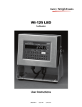
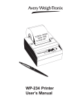
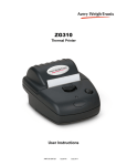
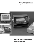
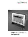
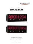
LED version ^
LCD version >
WI-125 SST Indicator
User’s Manual
CAUTION
Risk of electrical shock. Do not remove cover. No user serviceable parts inside. Refer servicing to qualified service personnel.
Weigh-Tronix reserves the right to change
specifications at any time.
July 2008 125SST_U.P65 PN 29629-0018 Issue AQ Printed in USA
2
WI-125 SST Indicator User’s Manual
Table of Contents
Table of Contents .........................................................................................3
Specifications ..............................................................................................4
Introduction ..................................................................................................5
Operations Mode ...................................................................................5
Keyboard ..............................................................................................5
Key Functions ..................................................................................6
Error Messages ...........................................................................................6
Indicator Operation ......................................................................................7
Powering Up ..........................................................................................7
Annunciators ..........................................................................................7
Gross/Tare/Net Weighing Operations ....................................................8
Gross Weighing ...............................................................................8
Net Weighing ...................................................................................8
Pushbutton Tare ...............................................................................8
Quick Keypad Tare Entry ..................................................................9
Selecting a Tare Register .................................................................9
Entering and/or Changing Values in Tare Registers..........................9
Clearing a Tare Register ................................................................10
Clearing the Active Tare .................................................................10
Net Weighing Operation .................................................................10
Entering Cutoff Values Through the Front Panel ...................................11
Controlling Cutoffs ...............................................................................11
To Access the Control Function ......................................................12
To Activate and Control Cutoffs ......................................................12
ID Number Entry ..................................................................................13
Viewing and Setting Time ..............................................................13
Viewing and Setting Date ...............................................................14
Single Accumulator with Counter ..........................................................15
Weighing and Printing ....................................................................15
Viewing Accumulated Weight and Count ........................................18
Enabling or Disabling Display Backlight ...............................................19
Operations Menu .................................................................................19
Indicator Diagnostics .................................................................................20
Test Mode ...........................................................................................20
Transmitting Data ......................................................................................22
RS-232 Output .....................................................................................22
Communication Protocol ................................................................22
Pages are numbered consecutively beginning with the cover page.
WI-125 SST Indicator User’s Manual
3
Specifications
Dimensions:
Power:
Display:
Display Averaging:
Display Rate:
8.25" x 6.25" x 4" (210mm x 159mm x 102mm) without bracket
10" x 9" x 5.5" (254mm x 229mm x 140mm) with bracket
115 volts AC @ 50 mA / 230 volts AC @ 25 mA, 50-60 Hz single phase
Optional - 12 VDC (LCD version only)
8 digits, 7-segment LCD or LED, 0.6 inch high with annunciators and backlighting (LCD only)
1 to 10 display periods
One, two or five times per second
Agencies:
NIST Handbook 44, Class III, IIIL, 10,000 divisions. LCD & LED - Certificate of Conformance #92-167.A4
Consumer and Corporate Affairs, Canada. LCD & LED Approval #AM4868
UL/CUL
CSA
FCC Class A
Accuracy :
Span: ±5.0 ppm/C
Span: ±10 ppm/C
Zero: ±.066 uV/C (-10 to 40°C)
Zero: ±0.13 uV/C (-30 to 60°C)
Linearity:
±0.005% of capacity, maximum
Repeatability:
±0.005% of capacity, maximum
Hysteresis:
Weigh bar drive capacity:
Environment:
Internal Resolution:
A to D conversion rate:
Analog Range:
0.005% of capacity, maximum
Up to eight 350 ohm weigh bars for LCD version. Up to twelve 350 ohm weigh bars for LED version.
-10 to 40°C (14 to 104°F) for HB-44 specs
10 to 90% relative humidity
810,000 at 3 mV/V. 1 mV/V = 270,000 counts
30 times per second (60/second for LED version)
-0.14 to +3.5 mV/V
Capacity:
0.1 to 999999, programmable to any number between these limits.
Divisions:
.0001 to 20000, programmable to any division size between these limits.
Push Button Zero Range:
0 to ±100% of capacity; programmable independent positive and negative limits; unit will not allow zeroing
beyond capacity.
Tare:
The unit may be configured to have pushbutton tare and numeric tare. Tares may tare only positive gross
weights up to the capacity of the unit.
Motion Detection Window:
Automatic Zero Tracking:
Programmable from 0 to 999999 divisions, decimal entries are accepted.
Window:
Programmable from 0 to 999999 divisions, decimal entries are accepted.
Net Mode
Tracking:
Rate:
Starting Delay:
Linearity Adjustment:
May be enabled or disabled
0.1 division per second
2 seconds
Second order correction provides smooth curve fit through three points--zero, linearity, span.
VIBRATION COMPENSATION
Analog Low Pass Filter:
Software Low Pass Filter:
4
Two section with .10 second time constant for low power analog and .06 second time constant for standard
analog.
One section with .05 second time constant.
WI-125 SST Indicator User’s Manual
Introduction
The WI-125 SST is a full featured indicator in a stainless steel enclosure
and includes a numeric keypad. The weight sensor interface termination and
RS-232 termination are made within the enclosure.
The socket-outlet must be
installed near the equipment
and easily accessible.
This set of instructions is divided into the following sections:
• Introduction
• Operations Mode
• Keyboard
• Indicator Operation
• Indicator Diagnostics
• Transmitting Data
• Specifications
Operations Mode
This manual is valid for Rev. F
or higher software.
Operations mode contains all normal weighing operations. In this mode you
can view or set the following parameters if the unit is so configured:
• push-button tare
• quick keypad tare entry
• one to ten tare registers (numbered 0-9)
• identification number
• time
• date
• backlight (LCD version only)
Any combination of these items can be secured behind a security code. Any
items secured by the code number can be viewed but not changed unless
you enter the security code.
Keyboard
The keyboard consists of 16 keys. Five keys, or buttons, provide all the
basic weighing functions:
• Tare
• G/N
• Zero
• Print
• Units
The other keys are used to access the menus for purposes of accessing
information, testing the indicator, and configuration. The keyboard is shown
in Figure 1.
Figure 1
WI-125 Keyboard
WI-125 SST Indicator User’s Manual
5
Enters a pushbutton tare in gross/net operation. During data
entry this key is used to toggle between positive and negative
values. Used to enter a dash (—) in ID numbers.
Key Functions
Accesses the gross weighing mode from any other function
and activates the net weighing mode if a tare is active.
Zeros the scale in gross or net weigh mode. This button also
clears keyed in digits on the display before they are accepted.
Sends a print command and is used to select menu items.
Used to access menus and move among choices in a menu.
Changes the unit of measure during operations mode. Inserts
a decimal point (.) when keying in values.
Error Messages
The following are displays you may see if problems occur or if invalid
operations are attempted with your WI-125:
Display
Description
Overrange weight.
Underrange weight.
Recovering from lock-up or out of range condition.
A-D converter is not functioning.
Corrupted data in the reset menus. See the Service Manual.
(* = RESET, SETUP, or CAL)
Displayed while a key is pressed when attempting to modify
a sealed selection without edit privileges.
BuSy
SEcured
6
Device on serial port is not ready to receive data.
User menu item is protected from changes by security code
number.
WI-125 SST Indicator User’s Manual
Indicator Operation
Powering Up
The unit will power up in gross or net weighing mode, depending on what
mode the unit was in when last turned off. All calibration, zero, gross and
tare values will be maintained during power loss.
The indicator display, Figure 2, tells you the status of the indicator through
the appearance of annunciators. In the LCD version, the annunciators are
small arrows pointing to the different labels around the display face. In the
LED version they are small labeled lights on the front panel.
The socket-outlet must be
installed near the equipment
and easily accessible.
Annunciators
Figure 2
Indicator Display (LCD version)
Annunciators
No annunciators appear while
motion is detected.
Gross - Appears when indicator is in gross weighing mode.
Net -
Appears when a tare is in effect and the indicator is in net weighing
mode.
Zero -
Appears when the scale is within ±1/4 division of zero.
Print - Appears when the print key is pressed and while data is transmitted.
lb, kg - Points out the active unit of measure in weighing mode.
WI-125 SST Indicator User’s Manual
7
Gross / Tare / Net
Weighing Operations
Gross Weighing
To perform gross/net weighing operations, follow these steps:
1. Power up the indicator.
2. If the unit is not in gross mode,
press the G/N key once to get to
gross mode.
3. Verify the scale is empty and
zero the scale by pressing the
ZERO key.
4. Select unit of measure by
pressing the UNITS button.
5. Place weight on the scale.
Net Weighing
Pushbutton Tare
You may view the current or
active tare value at any time
during a weighing process.
From gross or net weighing
mode, press MENU, TARE is
displayed, then press SELECT.
If a tare value is active, it will
be displayed. If no tare value is
active, NO TARE is displayed.
Press G/N to return to gross/
net weighing mode. Reference
the Operations Menu section
for menu details.
Indicator powers up in gross or net
mode.
The annunciator illuminates next to
gross. See Figure 2.
No weight is displayed and the zero
annunciator illuminates. See Figure
2.
The units annunciator will point to
the chosen unit of measure.
Gross weight is displayed.
For net weighing operations a tare needs to be entered. A tare can be
entered by three methods: using the pushbutton tare, using quick keypad
tare entry, or selecting a tare from the tare register (a memory bank of up to
ten tares).
1. With the scale empty and the
indicator powered up in gross
mode, zero the scale by pressing
the ZERO key.
2. Place the weight to be tared on
the scale.
3. Press the TARE key on the
indicator.
4. Add more weight to the scale.
5. View the gross weight by
pressing the G/N button.
No weight is displayed and the zero
annunciator illuminates.
The weight of the object is displayed.
The weight is tared, the display
reads zero and the net annunciator
illuminates.
Net weight is displayed.
Gross weight is displayed and the
gross annunciator illuminates.
6. Press the G/N key again to see net
weight.
Net weight is displayed and the net
annunciator illuminates.
8
WI-125 SST Indicator User’s Manual
Quick Keypad Tare Entry
1. From weigh mode, enter a tare
value using numeric keys 0-9.
2. Push TARE.
Selecting a Tare Register
2. Using the keypad, enter the
number of the tare register you
wish to use. (Numbers 0-9 are
allowed.)
3. With the correct tare register
displayed, press G/N.
Entering and/or Changing
Values in Tare Registers
Reference the Operations
Menu section for menu details.
Net weight is displayed and the net
annunciator illuminates.
Tare values must be entered in the tare registers before they can be used in
weighing operations. Refer to the section “Entering and/or Changing Values
in Tare Registers” at the bottom of this page.
1. From gross or net mode, press
MENU once or twice, depending
on options enabled, until . . .
If you wish to scroll through all
the tare registers, continue
pushing MENU. Stop when the
register you wish to use is
displayed.
Value is displayed as it is entered.
tArE is displayed.
That register with its tare value is
displayed.
Tare value is displayed in net mode.
1. With the gross or net annunciator
illuminated, press the MENU
button once or twice, depending
on options enabled, until. . .
tArE is displayed.
2. Using the keypad, enter the
number of the tare register you
wish to view. (Numbers 0-9 are
allowed. For this example, tare
register 5 will be used.) Key in
numeral 5.
WI-125 SST Indicator User’s Manual
The tare annunciator illuminates and
the display shows 5
0 , indicating
that register 5 has no value entered.
(Your indicator may have a value in
register 5.)
9
Clearing a Tare Register
3. You can enter/change a tare value
in a register in two ways:
3A. Key in a tare value:
With the desired
register number displayed,
key in 155 for this example,
then press PRINT/SELECT.
To set a tare register to 0, key
in 0
or
empty the scale and press
TARE.
The value 155 is accepted and tArE
is displayed.
or
3B. Use the pushbutton tare:
With the desired register
number displayed and the
container on the scale,
press TARE.
The register number and (container
weight) new tare value are displayed.
4. Press MENU to proceed to the
next tare register.
5. Press G/N to return to the
weighing mode.
Clearing the Active Tare
There are two ways to remove the current or active tare weight.
A. Remove all weight from the
scale and press TARE.
B. 1. With the gross or net
annunciator illuminated, press
MENU, then press CLEAR.
2. Press the G/N key.
Net Weighing Operation
1. After a tare is established, place
the indicator in net mode by
pressing the G/N key.
2. Place material to be weighed in
the tared container on the scale.
10
The value is accepted, net weight is
displayed and the net annunciator
illuminates.
WI-125 SST Indicator User’s Manual
The current active tare register is
cleared, scale returns to gross mode
and no weight is displayed.
tArE is displayed, then no tArE is
displayed.
Gross weight is displayed and no
tare is active.
Net annunciator illuminates. Zero
weight will be displayed with the
container on the scale.
Net weight of material is displayed.
Entering Cutoff Values
Through the Front Panel
Follow the steps below to enter a cutoff value. The cutoff output will be ON
below the value entered and OFF equal to or over the value entered.
1. Push the MENU key until
Cutoffs is displayed.
2. Push the SELECT key. . .
Cutoffs 0 to 7 are displayed.
3. Push the MENU key to scroll
through the cutoff channels.
4. Use the numeric keypad to enter
the cutoff values then press the
MENU or SELECT key.
Controlling Cutoffs
The WI-125 Indicator allows you to control the cutoff process from the front
panel. Through the WI-125 you may: enable/disable the cutoff process,
continue or interrupt the operation of a cutoff before its setpoint has been
reached, and/or terminate the process at any time before the last cutoff has
been reached.
There are two types of cutoffs in the WI-125: the ingredient cutoff and the
setpoint cutoff (default). With ingredient cutoffs, you tell the indicator the
weight of each ingredient you want and the indicator will call for that much of
each ingredient, no matter what the weight display says. If you want 100
pounds of ingredient #1 and 100 pounds of ingredient #2, you would enter 100
for cutoff #0 and 100 for cutoff #1.
With setpoint cutoffs, you tell the indicator at what weight display you want
the cutoffs to activate. In other words, if you want 100 pounds of ingredient
#1 and 200 pounds of ingredient #2, you would set the first setpoint cutoff at
100 and the second cutoff at 300 pounds because that is what the weight
display will read when you want the actions to occur.
Some menu items may not
appear in your particular
situation due to configuration
setup or firmware revision level.
You can tell which kind has been configured in your indicator by looking at
the cutoff number in the Operations menu shown below. If the cutoff number
has a decimal point following it, the cutoff is a setpoint type. If there is no
decimal, it is configured as an ingredient type.
WI-125 SST Indicator User’s Manual
11
To Access the Control
Function
Cutoff values (positive or
negative) must be entered
before you can control them.
To Activate and Control
the Cutoffs
1. From Gross/Net Weighing Mode,
press MENU one time. . .
Control is displayed.
2. With Control displayed, press
SELECT. . .
HALtEd is displayed.
There are two ways--Methods A or B--to activate the cutoffs. Method A
activates the cutoffs immediately while displaying the changing weight on
the scale, and Method B allows you to view the weight on the scale before
the cutoffs are activated.
Method A:
1. With HALtEd displayed, press
MENU. . .
2. Press SELECT. . .
Method B:
1. With HALtEd displayed, press
SELECT...
2. Press MENU....
To halt active cutoffs
12
r xxxxxx is displayed. xxxxxx
represents the weight as it changes
on the scale.
h xxxxxx is displayed. xxxxxx
represents the weight on the scale.
r xxxxxx is displayed. xxxxxx
represents the weight as it changes
on the scale.
You may halt an active cutoff at any time.
With r xxxxxx displayed, press any
key. . .
To return to Gross/Net
Weighing Mode
run is displayed.
You may return to G/N Weighing
Mode at any time during this process
by pressing GROSS/NET...
WI-125 SST Indicator User’s Manual
h xxxxxx is displayed and cutoffs
are halted.
Display returns to G/N Weighing
Mode.
ID Number Entry
Reference the Operations
Menu section for menu details.
You may enter an ID number of up to 8 digits in length. The ID number may
include any combination of the numbers 0 through 9, a dash and a decimal
point.
1. From gross weighing mode,
press MENU repeatedly. . .
id. is displayed.
2. Press SELECT . . .
The current ID number is displayed.
3. With the current ID number
displayed, enter a numerical
value for your ID number using
the keypad.
The new ID number is displayed.
4. After your new ID number has
been displayed, press
SELECT. . .
id. is displayed.
5. Press G/N to return to the
weighing mode.
Viewing and Setting
Time
Display returns to gross or net
mode.
Your indicator must have the appropriate circuitry and be configured to allow
the following:
1. From gross/net weighing mode,
press MENU repeatedly until . . . . Hour is displayed.
Reference the Operations
Menu section for menu details.
2. Press SELECT. . . .
In the 12 hour clock configuration
you will see time displayed as hours,
minutes and A for A.M. or P for P.M.
(09.40 A). In the 24 hour clock you
will see hours, minutes and seconds
(09.40.38).
If you enter an incorrect digit,
press ZERO/CLEAR to clear
the display one digit at a time.
3. To set the 12 hour clock, use the numeric keypad to enter the correct
time.
a. Key in the time as hh mm.
b. Press the TARE key to
toggle between AM & PM.
c. After the correct time is
entered, press SELECT to
accept the new time.
Hour is displayed and clock begins.
d. Press G/N to return to the
weighing mode.
Display returns to weigh mode.
To set the 24 hour clock, use the numeric keypad to enter the correct
time.
a. Key in time as hh mm ss.
b. After the correct time is
entered, press SELECT to
accept the new time.
Hour is displayed and the clock
begins.
c. Press G/N to return to the
weighing mode.
Display returns to gross/net mode.
WI-125 SST Indicator User’s Manual
13
Viewing and Setting
the Date
Reference the Operations
Menu section for menu details.
Your indicator must have the appropriate circuitry and HOUR must be
enabled and set correctly to allow the following:
1. From gross/net weighing mode,
press MENU repeatedly until . . .
2. Press SELECT.
If you enter an incorrect digit,
press CLEAR to clear the
display one digit at a time.
dAY is displayed.
Depending on the configuration of
your indicator you will see the date
displayed in one of three ways:
• month-day-year, or
• day-month-year, or
• year-month-day.
3. To change the date, key in the new
date using the numeric keypad.
4. Press SELECT to return to the
operations mode menu
The old date is replaced with the
new date.
or
press G/N to return to gross/net
weighing mode.
14
WI-125 SST Indicator User’s Manual
The date is accepted and dAY is
displayed.
Single Accumulator
with Counter
There is a single channel accumulator in both the LED and LCD model
indicators. The accumulator will add the displayed weights automatically and
print individual weights and totals on command.
Weighing and Printing
1. Weigh load. . .
Indicator displays weight.
2. Press PRINT. . .
Weight is printed.
3. For each additional load weighed,
press PRINT. . .
Printing the accumulated
weight and count can be
accomplished at any time
during the weighing process;
however, printing these
values automatically clears
them from memory! So take
care to print the accumulated
values only after you have
made all the necessary
weighments.
A print/add function will occur if
you have autoprint enabled or
if a remote Print command is
received by the indicator.
WI-125 LED is configurable for
LP02844 labels
4. After the last load has been
weighed and printed, press
MENU, then TARE. . .
G
G
G
Count
Total
Each weight is printed individually
and the weight is totalled automatically within the indicator.
The total weight and count are
printed and cleared from memory.
210 lb
200 lb
200 lb
3
610 lb
WP-233 Tape printer sample printout
WI-125 SST Indicator User’s Manual
15
Sample 1
Orion 1 Label
Sample 2
Orion 2 Label
Sample 3
Orion 3 Label
Sample 4
Barcode Label
16
WI-125 SST Indicator User’s Manual
The following label samples show the "Total" label available when using the ACCUM function in the LED version of the
WI-125 indicator. See the ACCUM function.
Sample 5
Orion 1 "Total"
Label
Sample 6
Orion 2 "Total" Label
Sample 7
Orion 3 "Total" Label
Sample 8
Barcode "Total" Label
WI-125 SST Indicator User’s Manual
17
Viewing Accumulated
Weight and Count
GROSS may be pressed at any
time during viewing to return to
weighing mode.
18
1. With weight displayed, press
MENU until. . .
ACC is displayed.
2. Press PRINT/SELECT. . .
Total weight of all loads is displayed.
3. Press PRINT/SELECT to toggle
back to ACC. . .
ACC is displayed.
4. Press MENU once. . .
count is displayed.
5. Press PRINT/SELECT. . .
Total number of loads is displayed.
6. Press PRINT/SELECT to toggle
back to count. . .
count is redisplayed.
7. Press G/N to return to weighing
mode. . .
Current weight is displayed.
WI-125 SST Indicator User’s Manual
Enabling or Disabling
Display Backlight
1. From gross/net weighing mode,
press MENU repeatedly until . . .
2. Press SELECT.
Backlight available on LCD
version only.
Operations Menu
ENABLED or diSAbLEd is displayed
3. Press MENU to toggle between
enabled or disabled.
4. Press SELECT to return to the
operations mode menu
Configuration choice (ON/OFF/
AUTO) made during setup of
this unit will determine if the
backlight is on constantly or if it
varies according to ambient
light levels. Refer to the
Service Manual.
Light is displayed.
or
press G/N to return to gross/net
weighing mode.
The light selection is accepted and
Light is displayed.
The light selection is accepted and
the display returns to gross/net
mode.
Your WI-125 SST may be configured to display some or all of the following
functions: tare, id, time, date, accumlator, count, and backlight. These can
be viewed and changed if allowed by the security code. This manual
assumes the unit is configured to allow full access to all functions.
You can disable unneeded options. Instructions are in the Service Manual.
Below is a flowchart and general instructions for moving around the operations mode menu. The instructions in the preceding sections outlined the
steps in detail for moving around in this menu. Use this flowchart as a quick
reference to maneuver through the operations mode menu.
Figure 3
Operations Menu
Press MENU to move Æ in the diagram
Press and hold MENU for 1.5 seconds to move Å in the diagram
Press PRINT/SELECT to move È in the diagram
Press PRINT/SELECT for 1.5 seconds to select new choice and move Ç in
the diagram
Press G/N at any time to save changes and return to gross/net weighing
mode
WI-125 SST Indicator User’s Manual
19
Indicator Diagnostics
Test Mode
The test mode is used to test various functions of the WI-125. The test
menu is shown in Figure 4. Instructions for using the test menu are found
below.
Figure 4
Test Menu
Press MENU to move Æ in the diagram
Press and hold MENU for 1.5 seconds to move Å in the diagram
Press PRINT/SELECT to move È in the diagram
Press PRINT/SELECT for 1.5 seconds to select new choice and move Ç in
the diagram
Press G/N at any time to save changes and return to gross/net weighing
mode
1. Enter the test mode from gross/net operation by pressing and holding
the MENU key until tESt is displayed. SEALEd or unSEALEd is displayed briefly while you hold the key. If you release the MENU key too
soon, press G/N to return to normal weigh mode and begin again.
2. Move to the right through the menu selections by pressing MENU
briefly. Move to the left through the menu selections by pressing MENU
for 1.5 seconds or hold down for continuous scrolling.
20
WI-125 SST Indicator User’s Manual
3. To move down a level in the hierarchy, press SELECT. Anytime you
wish to get to the next higher level in the hierarchy, press and hold
SELECT for approximately 1.5 seconds or press SELECT whenever
End is displayed.
4. Press MENU to toggle between choices.
5. Press G/N to return to gross weighing operation at any time.
Below are the specific directions and explanations for the items you see in
the test menu.
VERSION —
Under VErSIOn are the Weigh-Tronix part number and
revision number for the software found in your machine.
Weigh-Tronix part numbers are divided into two parts: the
prefix and the dash number. With VErSIOn displayed, press
SELECT to view the prefix, then push MENU to view the
dash number. Press SELECT to return to VErSIOn.
DISPLAY —
With diSPLAY displayed, press SELECT and the bottom
row of annunciators turns on. Press SELECT again and a
dynamic test is run. Press MENU to stop the dynamic test
or consecutively press MENU to step through the display
test routine. Press SELECT when the dynamic test is active
to return the unit to diSPLAY.
BUTTONS —
With buttonS displayed, press SELECT and an underscore
will appear on the screen. Press any key except MENU to
check for proper key functioning. After testing the buttons,
press MENU to return to the display.
OUTPUTS —
These tests allow you to turn the cutoffs on and off automatically in sequence, under SEQUENCE, or individually,
under CUTOFF 0-7. When you exit the outputs test, the
cutoffs revert to their proper condition according to the
weight on the scale.
A to D —
Displays the analog to digital counts. The span is normally
20000 counts per millivolt per volt. With a calibrator at zero
millivolts per volt, the displayed value should be between
-200 and +200. Press SELECT to return to A to D.
SERIAL —
Tells you if the serial output is ready or busy. A jumper
connecting pins DTR to CTS of the serial port will cause
REAdY to be displayed. Pressing the MENU key puts no
LOOP on the display. With pins XMITT to RECV connected,
LOOP is displayed. With them disconnected, no LOOP is
displayed. Press SELECT to return to SErIAL.
WI-125 SST Indicator User’s Manual
21
Transmitting Data
The WI-125 SST provides an RS-232 output for data transmission to a
peripheral device. Refer to the Service Manual for RS-232 interface connections.
RS-232 Output
To transmit data, follow these instructions:
If your indicator has a peripheral device
connected, from the gross/net weighing
mode press the PRINT key to transmit
the selected output(s).
The PRINT annunciator (See Figure
2) will illuminate while data is
transmitted and the data configured
to be printed will be output to the
printer. See Figure 5 for a sample
printout.
Communication protocol
Samples of the default printout for a WI-125 SST are shown in Figure 5.
This is the displayed weight (Gross or Net) followed by a carriage return and
line feed.
An enquire code can be sent to the WI-125 SST. This will prompt the
indicator to send a standard printout. The default enquire code number is an
ASCII decimal 005. This number can be changed in configuration.
G
1500 lb
N
or
0500 lb
Figure 5
The default settings for serial output are:
Busy
Baud
Parity
Stops
22
Disabled
1200
Clear = 8 data, no parity
1
Stop Bits
Data Bits
Parity
NONE
1 or 2
7 or 8
None
ODD
1 or 2
7
Odd
EVEN
1 or 2
7
Even
SET
2
7
None
CLEAR
1
8
None
WI-125 SST Indicator User’s Manual
WI-125 SST Indicator User’s Manual
23
Avery Weigh-Tronix USA
1000 Armstrong Dr.
Fairmont MN 56031 USA
Tel: 507-238-4461
Fax: 507-238-4195
Email: [email protected]
www.wtxweb.com
Avery Weigh-Tronix UK
Foundry Lane,
Smethwick, West Midlands,
England B66 2LP
Tel: +44 (0) 8453 66 77 88
Fax: +44 (0)121 224 8183
Email: [email protected]
www.averyweigh-tronix.com
Weigh Bar® is a registered trademark of Weigh-Tronix Inc.