1
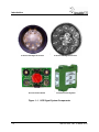
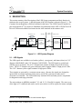
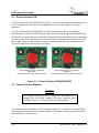
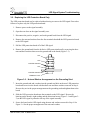
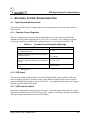
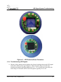
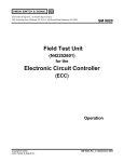
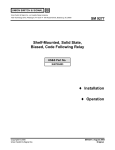
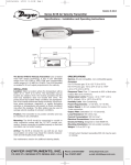
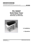
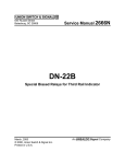
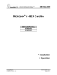
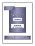
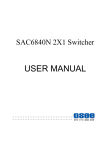
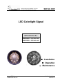
SM-7A1.0001
1000 Technology Drive, Pittsburgh, PA 15219
645 Russell Street, Batesburg, SC 29006
LED Colorlight Signal
.
ASTS USA Part No
N4620440X – 6 3/8 inch unit
N4621280X – 8 3/8 inch unit
Installation
Operation
Maintenance
Copyright© 2010
Ansaldo STS USA, Inc.
SM-7A1.0001, Rev. 2
March 2010
Notices
Proprietary Notice
This document and its contents are the property of Ansaldo STS USA,
Inc. (formerly known as Union Switch & Signal Inc., and hereinafter
referred to as "ASTS USA"). This document is furnished to you on the
following conditions: 1.) That no proprietary or intellectual property
right or interest of ASTS USA is given or waived in supplying this
document and its contents to you; and, 2.) That this document and its
contents are not to be used or treated in any manner inconsistent with
the rights of ASTS USA, or to its detriment, and are not to be copied,
reproduced, disclosed or transferred to others, or improperly disposed
of without the prior written consent of ASTS USA.
Important Notice
ASTS USA constantly strives to improve our products and keep our customers apprised of
changes in technology. Following the recommendations contained in the attached service manual
will provide our customers with optimum operational reliability. The data contained herein
purports solely to describe the product, and does not create any warranties.
Within the scope of the attached manual, it is impossible to take into account every eventuality
that may arise with technical equipment in service. Please consult an ASTS USA local sales
representative in the event of any irregularities with our product.
ASTS USA expressly disclaims liability resulting from any improper handling or use of our
equipment, even if these instructions contain no specific indication in this respect. We strongly
recommend that only approved ASTS USA spare parts are used as replacements.
SM-7A1.0001, Rev. 2, March 2010
i
Revision History
Revision History
ii
Rev.
Date
Nature of Revision
1
September 2008
Initial Release
2
March 2010
Revised Figure 1–1, Figure 2–3, and Figure 4–1.
Revised Section 2.3.
SM-7A1.0001, Rev. 2, March 2010
Table of Contents
Table of Contents
1.
INTRODUCTION ................................................................................................................................ 1-1
2.
DESCRIPTION ................................................................................................................................... 2-1
2.1. LED Signals .............................................................................................................................. 2-1
2.2. Driver Protection PCB............................................................................................................... 2-2
2.3. Constant Current Regulator...................................................................................................... 2-2
2.4. Supplying Power....................................................................................................................... 2-4
3.
LED SYSTEM INSTALLATION ......................................................................................................... 3-1
3.1. Installing an LED Signal with LED Protection PCB .................................................................. 3-1
3.2. Replacing the LED Protection Board Only ............................................................................... 3-3
3.3. Signal and Protection Board Wiring.......................................................................................... 3-4
4.
LED SIGNAL SYSTEM TROUBLESHOOTING ................................................................................ 4-1
4.1. Typical System Measurements................................................................................................. 4-1
4.1.1. Constant Current Regulator..........................................................................................4-1
4.1.2. LED Signal ....................................................................................................................4-1
4.1.3. LED Protection Board ...................................................................................................4-1
4.1.4. Troubleshooting LED Signals .......................................................................................4-3
5.
MAINTENANCE ................................................................................................................................. 5-1
5.1. General Maintenance ............................................................................................................... 5-1
5.2. Cleaning.................................................................................................................................... 5-1
5.3. LED Signal Replacement.......................................................................................................... 5-1
6.
PARTS LIST ....................................................................................................................................... 6-1
7.
RAIL TEAM AND TECHNICAL SUPPORT ....................................................................................... 7-1
SM-7A1.0001, Rev. 2, March 2010
iii
Table of Contents
List of Figures
Figure 1–1.
LED Signal System Components..................................................................................... 1-2
Figure 2–1.
LED System Diagram....................................................................................................... 2-1
Figure 2–2.
Driver Protection PCB (N4620520X) ............................................................................... 2-2
Figure 2–3.
Constant Current Regulator (N34801401)....................................................................... 2-3
Figure 2–4.
ASTS USA LED Signal System Block Diagram............................................................... 2-4
Figure 3–1.
Rear View of the 6 & 3/8 Inch LED Signal ....................................................................... 3-2
Figure 3–2.
Rear View of the 8 3/8 Inch LED Signal...........................................................................3-2
Figure 3–3.
Nut and Washer Arrangement on the Grounding Stud.................................................... 3-3
Figure 3–4.
Nut and Washer Arrangement on the Terminals ............................................................. 3-4
Figure 4–1.
Pins on the Constant Current Regulator.......................................................................... 4-2
Figure 4–2.
LED Protection Board Orientation.................................................................................... 4-3
List of Tables
Table 3-1.
Maximum Signal Distance from the Signal House........................................................... 3-5
Table 4-1.
Constant Current Regulator Readings............................................................................. 4-1
Table 6-1.
Part Numbers for the ASTS USA LED Signal System Components ............................... 6-1
iv
SM-7A1.0001, Rev. 2, March 2010
Introduction
1. INTRODUCTION
The ASTS USA LED light Signal System consists of the LED signals (in four distinct colors), a
6 3/8 inch diameter unit (N4620440X), and a 8 3/8 inch diameter unit (N4221280X) complete
with the LED Protection Board (N46205001), a Constant Current Regulator (N34801401), and a
Driver Protection PCB (N4620520X).
Each LED signal contains several high-intensity LEDs which operate on a constant current
provided by the constant current regulator. The Driver Protection PCB is in series with the signal
and provides surge protection for the signal.
The components of the system are ordered separately and installed as a system based on the
specific application of the signals. All of the components of the system are shown in Figure 1–1.
SM-7A1.0001, Rev. 2, March 2010
1-1
Introduction
6 3/8 Inch LED Signal Front View
Driver Protection Board
8 3/8 Inch LED Signal Front View
Constant Current Regulator
Figure 1–1. LED Signal System Components
1-2
SM-7A1.0001, Rev. 2, March 2010
System Description
2. DESCRIPTION
This section contains a brief description of the LED System components and their function in
relation to the overall system. A block diagram of the LED System is shown in Figure 2–1. The
Constant Current Regulator is DIN-rail mounted in the house. The LED12 board is installed as
part of the MicroLok ® II system (see SM6800N for information on the LED 12 PCB) The LED
Driver PCB Protection Board is mounted on the AAR terminals at the entrance rack.
G96 BUS to CPU
VCOR
Contact
Constant Current
Regulator
(N34801401)
LED 12
PCB
(N17066101)
Output
Battery
WAYSIDE
LED Driver
PCB
Protection Board
(N4620520x)
FIELD
WIRING
SIGNAL HEAD
LED Signal
Protection Board
(N46205001)
LED Signal
(N4620440x)
(N4621280x)
Figure 2–1. LED System Diagram
2.1. LED Signals
The LED signals are available in red, amber (yellow), cyan (green), and lunar (white) in 6 3/8”
diameter (N4620440X) and 8 3/8” diameter (N4621280X). The LED signal is a sealed unit
(NEMA type 4 enclosure). The 6 3/8” diameter unit contains 10 high power LEDs wired in
series. The 8 3/8” diameter red, green, and lunar (white) signals contain 12 high power LEDs.
The 8 3/8” diameter yellow signal contains 14 high power LEDs
These signals are powered by a constant current source. Because the signals are designed to
operate with an external constant current source; no DC/DC converters or other active
electronics are included. The LED module only includes LEDs and other passive components
for diagnostics and surge protection.
The unit conforms to AREMA standards 7.1.5 and 11.5.1 (Class B) for signals. The outer cover
of the light is UV stabilized and can be used in areas where it will be exposed to intense sunlight.
Microlok® is a registered trademark of Union Switch & Signal
SM-7A1.0001, Rev. 2, March 2010
2-1
LED System Description
2.2. Driver Protection PCB
The Driver Protection PCB (N4620520X) (Figure 2–2) is an entrance panel mounted board. It is
used in combination with ASTS USA lightning arrestors to provide a high level of surge
protection.
The Driver Protection PCB (N46205201), which is mounted in the house, is designed to
terminate house wiring on the left hand side of the board and field wiring on the right hand side
of the board. An optional version of the Driver Protection PCB (N46205202) allows terminating
the house wiring on the right hand side of the board and field wiring on the left hand side of the
board. Both versions of the board use the same components and allow the components to be
viewed for inspection when mounted in the house.
DRIVER BOARD PROTECTION PCB
(N46205201)
HOUSE WIRING ON LEFT SIDE OF BOARD
DRIVER BOARD PROTECTION PCB
(N46205202)
HOUSE WIRING ON RIGHT SIDE OF BOARD
Figure 2–2. Driver Protection PCB (N4620520X)
2.3. Constant Current Regulator
CAUTION
The constant current regulator is designed to be installed on a
standard DIN rail. When installed with other regulators there
should be at least a 1/2” separation between the regulators.
The Constant Current Regulator (CCR) (N34801401) (Figure 2–3) provides a constant 350mA
regulated current output for driving the LED signals. The output of the regulator includes both
open and short circuit protection.
2-2
SM-7A1.0001, Rev. 2, March 2010
System Description
The CCR has a non-vital output that is derived from the internal monitoring function of the CCR.
It is not required that the non-vital output circuit be used. The non-vital output is capable of
driving 400 ohm relay coils.
If the output voltage of the CCR goes below 33 volts ± 2 volts, the non-vital output of the CCR
will go to 0 volts. If the output voltage of the CCR is above 33 volts ± 2 volts, the non-vital
output of the CCR will be approximately equal to the battery voltage (depending upon load
impedance).
Note
Only ASTS USA Constant Current Regulators are to be used with
the ASTS USA LEDs. A regulator is required for each “ON” LED
signal in a system; however, a regulator can be shared between
signals that will never be on at the same time.
Figure 2–3. Constant Current Regulator (N34801401)
The power consumption of the constant current regulator is:
With the Regulator Powered and the LED signal ON - 20W
With the Regulator Powered and the LED signal OFF - 0.6W
SM-7A1.0001, Rev. 2, March 2010
2-3
LED System Description
2.4. Supplying Power
The ASTS USA LED Signal System is designed for use with a Microlok II unit or an Object
Controller (Series 4000). See Service Manual SM 6800N for application information with a
Microlok II unit. The ASTS USA LED Signal operates from an external constant current source.
This design allows for accurate monitoring of the operational state of the LED devices in the
signal.
Figure 2–4 illustrates the ASTS USA LED Signal System. This system differs from the typical
existing system in that the signal load is powered by an external regulated current source (rather
than a voltage source) which is applied and removed from the signal load via a softwarecontrolled switch.
US&S
CONSTANT
CURRENT
REGULATOR
350mA
SOFTWARE CONTROLLED
SWITCH
OR
RELAY CONTACT
+
US&S LED SIGNAL
_
7A1.0013.00
BATTERY
(9.8 - 16.2V)
Figure 2–4. ASTS USA LED Signal System Block Diagram
2-4
SM-7A1.0001, Rev. 2, March 2010
LED Signal System Troubleshooting
3. LED SYSTEM INSTALLATION
3.1. Installing an LED Signal with LED Protection PCB
When an individual LED signal, complete with the LED Protection PCB (N46205001), needs to
be installed, follow this procedure.
1. Remove power to the signal.
2. Open the rear door of the signal assembly. If the old LED signal has not been removed,
remove it in accordance with the procedure found in Section 3.2.
3. Place the new LED signal into the case and position it in the opening in the front of the
case. The LED signal should be oriented with the text on the LED protection board right
reading (Figure 3–1 and Figure 3–2).
4. Secure the LED signal to the case.
5. Connect the positive lead to TL2 and negative lead to the TL1 on the LED signal.
6. Connect the ground wire to the Earth Ground terminal on the LED signal.
7. Apply power to the signal assembly and verify that the LED signal is lit.
8. Close the signal case door.
SM-7A1.0001, Rev. 2, March 2010
3-1
LED Signal System Troubleshooting
Figure 3–1. Rear View of the 6 & 3/8 Inch LED Signal
Figure 3–2. Rear View of the 8 3/8 Inch LED Signal
3-2
SM-7A1.0001, Rev. 2, March 2010
LED Signal System Troubleshooting
3.2. Replacing the LED Protection Board Only
The LED protection board can be replaced without having to remove the LED signal. Proceed as
follows to replace only the LED protection board:
1. Remove power to the signal assembly.
2. Open the rear door on the signal assembly case.
3. Disconnect the positive, negative, and earth ground leads from the LED signal.
4. Remove the nuts and washers from the four terminals that hold the LED protection board
to the LED signal.
5. Pull the LED protection board off of the LED signal.
6. Remove the ground stud from the defective LED protection board by removing the three
nuts and three washers that secure the ground stud to the board (Figure 3–3).
NUT
NUT
COPPER WASHER
NUT
COPPER WASHER
TERMINAL POST
Figure 3–3. Nut and Washer Arrangement on the Grounding Stud
7. Insert the ground stud and a washer into the ground stud hole on the new LED protection
board and secure it to the board with the three nuts and three washers removed in Step 6.
Be sure they are in the proper arrangement on the grounding stud and tighten them to the
board.
8. Slide the LED protection board onto the terminals on the LED signal. Be sure the
lettering on the board is right reading and the directional arrow (Figure 3–1 and Figure 3–
2) on the LED signal is pointed to the top of the signal assembly.
9. Secure the board on the LED signal using the nuts and washers removed in Step 4. See
Figure 3–4 for the proper arrangement of the nuts and washers.
SM-7A1.0001, Rev. 2, March 2010
3-3
LED Signal System Troubleshooting
10. Connect the positive and negative leads to the top terminals of the LED signal. Be sure
to observe the proper polarity when connecting the wires to the LED signal. The positive
terminal is on the left and the negative terminal is on the right. The proper polarity is
printed on the LED protection board.
11. Apply power to the signal assembly and verify that the LED signal is lit.
12. Close the signal case door.
WASHERS
WASHERS
NUTS
NUTS
TERMINAL POST
TERMINAL POST
NUTS
NUTS
NUTS
NUTS
TERMINAL POST
WASHERS
7A1.0008.00
TERMINAL POST
WASHERS
Figure 3–4. Nut and Washer Arrangement on the Terminals
3.3. Signal and Protection Board Wiring
Table 3-1 summarizes the maximum distance a signal can be located from the signal house based
on the wire gauge selected for the application. As noted in the table, the distances already
include the series resistance of all the lightning/surge protection circuitry. However, the series
resistance of additional components such as house wiring, relay contacts, and terminal
connections will reduce the maximum distance for a signal (they will need to be included in the
3-ohm limit for each leg).
3-4
SM-7A1.0001, Rev. 2, March 2010
LED Signal System Troubleshooting
Table 3-1.
6
8
9
10
12
14
Wire Gauge
(AWG)
Maximum Signal Distance from the Signal House
Ohms per 1000 ft
0.3951
0.6282
0.7921
0.9989
1.588
2.525
Maximum signal distance
(wire length for each leg)
7500 ft
4700 ft
3700 ft
3000 ft
1800 ft
1100 ft
Note 1
Distances are based on maximum line resistance of 3 ohms per leg (6 ohms total).
Note 2
Distances include series resistance of all lightning/surge protection circuits.
Note 3
Additional series resistance of house wiring, relay contacts, terminal connections, etc. will reduce
the maximum distances allowed.
The following is a list of wiring specific requirements/notes for the ASTS USA LED Signal
System:
•
For all applications, the use of the lightning/surge protection components of the LED
signal system is recommended.
•
ASTS USA recommends the use of twisted pair wiring (two to three turns per foot) to
minimize possible noise. This should be done wherever possible on all I/O wiring.
•
ASTS USA recommends the physical separation of clean and noise generating wiring.
Ideally, all outputs are gathered in one bundle, inputs are gathered in another bundle, and
power wiring is gathered in a third bundle. Each of these bundles is physically separated
from each other (6” preferred) and all bundles are physically separated from other house
wiring. It is particularly important to maintain this physical separation from high-current,
noise generating wiring.
•
All field wiring should be configured to minimize cross talk between wires. Cables and
wires should be kept as short as possible to minimize induced line noise. Case/house
wiring layouts should also be arranged to minimize noise. Battery leads should be as
short as possible and must be isolated as much as possible from noisy wiring.
•
Additional loads, such as local indicators, cannot be connected across the signal leads of
the LED signal.
•
Multiple signals cannot be wired in series or parallel (i.e., color position lights must be
separately wired to individual constant current sources).
•
The outputs of multiple constant current sources should not be connected in parallel or
series.
•
Fuses are not needed/recommended on the signal outputs; the ASTS USA constant
current regulator output includes short-circuit protection, and no damage will occur to the
system if an output is inadvertently shorted to ground. Fuses can be installed on the
SM-7A1.0001, Rev. 2, March 2010
3-5
LED Signal System Troubleshooting
system battery connections to the system as required. (These fuses can be installed in the
circuit between the VCOR-1 and terminal B12).
3-6
•
Slide-wire resistors are not required for use with the LED signals and should never be
installed. Also, the LED signals cannot be dimmed by wiring in a series resistance.
•
The LED signal has five terminals which are clearly marked (two require a field
connection; one is for ground surge protection, and two have no external connection).
Ensure that the connections are made to the proper terminals.
•
The LED signal field terminals have a polarity that must be observed, where incandescent
signals typically do not. A signal hooked up with reversed polarity will not operate and
could eventually damage the signal.
SM-7A1.0001, Rev. 2, March 2010
LED Signal System Troubleshooting
4. LED SIGNAL SYSTEM TROUBLESHOOTING
4.1. Typical System Measurements
This section provides a list of voltage and/or current measurement for a good system and for a
faulty system.
4.1.1. Constant Current Regulator
Table 4-1 summarizes the expected measurements that can be observed from a functional
constant current regulator operating off of a 9.8 to 16.2-volt source. Any readings outside the
stated ranges indicate a possible faulty regulator. Figure 4–1 gives the pinout of the CCR.
Table 4-1.
Constant Current Regulator Readings
CONDITION
Voltage at output with no load connected
(pin 4 referenced to pin1)*
Voltage at output with resistive load connected (pin
4 referenced to pin1)*
EXPECTED READING
V = ~58V
V = 0.35 * R +/-10%, where
R <= 140ohms
Voltage at output with a known good LED Signal
connected - signal ON condition (pin 4 referenced
to pin1)*
29V <= V <= 50V
Current output with valid load - signal ON condition
(pin 4)*
I = 350mA ±10%
*
See Figure 4–1.
4.1.2. LED Signal
The expected voltage readings taken across the LED Signal field wiring terminals will be the
same or slightly less (due to resistance in the wiring) than the readings taken across the driver
protection board field terminals as given in Table 4-1. Any readings outside of the stated ranges
indicate a possible faulty LED signal.
4.1.3. LED Protection Board
Inspect the components for signs of stress or damage. If present, replace the board with a spare
and return the faulty board to ASTS USA for repair. Figure 4–2 illustrates the proper orientation
of the protection board on the back of the LED signal.
SM-7A1.0001, Rev. 2, March 2010
4-1
LED Signal System Troubleshooting
NOT USED
N12
1
2
3
4
B12
LED OUTPUT
CONSTANT
CURRENT
REGULATOR
MODULE
N12
5
6
7
8
NOT USED
7A1.0009.00
NON-VITAL
OUTPUT
Figure 4–1. Pins on the Constant Current Regulator
4-2
SM-7A1.0001, Rev. 2, March 2010
LED Signal System Troubleshooting
Figure 4–2. LED Protection Board Orientation
4.1.4. Troubleshooting LED Signals
•
Because of the constant current regulator, the electrical readings taken at the LED signal
load will be different from typical signals. Where the load voltage of an ON-state
incandescent signal is typically at battery level (i.e., 12V or lower due to line drop), the
load voltage of a ON-state ASTS USA LED signal is typically 35V to 42V.
SM-7A1.0001, Rev. 2, March 2010
4-3
LED Signal System Troubleshooting
4-4
•
The LED signal cannot be checked for operation (energized) by applying battery voltage
directly to its terminals. A constant current regulator or equivalent current source is
required to light the signal. Also, an ohmmeter across the terminals of the signal will not
provide an indication of the signal’s integrity.
•
The LED signal has five terminals which are clearly marked (three require a field
connection; two have no external connection). Ensure that the connections are made to
the proper terminals.
•
The LED signal field terminals have a polarity that must be observed, where
incandescent signals typically do not. A signal hooked up with reversed polarity will
not operate and could eventually damage the signal.
•
Slide-wire resistors are not required for use with the LED signals and should never
be installed. Also, the LED signal cannot be dimmed by switching in a series
resistance, as can typically be done with an incandescent signal.
•
When used in combination with the Vital Output LED12 PCB, an OFF-state ASTS USA
LED signal will have a load voltage of approximately -2.5V. This voltage level is normal
and is present because OFF-state diagnostics are being performed by the control system.
•
The diagnostic and light-out detection functions of the Vital Output LED12 PCB do not
use external “check pulses.” For both ON- and OFF-state LED signals, a “check pulse”
will never be seen at the load.
•
The LED12 PCB will detect shorts between signals that cause an incorrect signal state. If
the return leads (-) of any two or more signals are shorted together the system will not
indicate an error, because this is a legal wiring option. If the controlled lead (+) of two or
more signals are shorted together the system will not indicate an error if all of the signals
are in the same state, all on or all off. If a wiring short causes an off-state signal to turn
on then a critical error will occur and the Microlok II system will reset.
SM-7A1.0001, Rev. 2, March 2010
LED Signal System Troubleshooting
5. MAINTENANCE
5.1. General Maintenance
Maintenance consists of performing routine cleaning and replacing the non-functional LED
signals. Repair of damaged units is limited to replacing component parts in the field. Should the
signal assembly sustain any damage, it is recommended that the complete assembly be replaced.
The LED signal requires no focusing. Maintenance primarily consists of periodically cleaning
the face of the LED signal and replacing any non-functional LED signal.
5.2. Cleaning
The front surface of the LED signal should be cleaned with a Lexan cleaner using a soft,
nonabrasive, cloth. The exterior of the case may be cleaned with a soft dry cloth, paper towel, or
brush.
NOTE
Dirt and dust that collect on the exposed surface of the outside of
the LED signal should be removed periodically to maintain the
normal range of the signal.
5.3.
LED Signal Replacement
The optical system of the LED signal contains no field-replaceable parts. It must be replaced as a
unit when it is defective. Replace the LED signal per Section 3.1.
Caution
When replacing the LED signals, ensure that the LED signal being
replaced is replaced by an LED signal of the same color. If a red
LED signal is being replaced, ensure that a red LED signal is used
to replace it and not one of another color.
SM-7A1.0001, Rev. 2, March 2010
5-1
LED Signal System Troubleshooting
5-2
SM-7A1.0001, Rev. 2, March 2010
Parts List
6. PARTS LIST
This section provides the part numbers for all system components.
Table 6-1.
Part Numbers for the ASTS USA LED Signal System Components
PART NUMBER
DESCRIPTION
N34801401
Constant Current Regulator Module
N46205201
Driver Protection Board (House wiring on left)
N46205202
Driver Protection Board (House wiring on right)
N46205001
LED Protection Board (mounted on LED Signal)
N46204401
LED Signal, Red, 6 3/8”
(includes LED Protection Board – N46205001)
N46204402
LED Signal, Cyan (Green), 6 3/8”
(includes LED Protection Board – N46205001)
N46204403
LED Signal, Amber (Yellow), 6 3/8”
(includes LED Protection Board – N46205001)
N46204404
LED Signal, Lunar (White), 6 3/8”
(includes LED Protection Board – N46205001)
N46212801
LED Signal, Red, 8 3/8”
(includes LED Protection Board – N46205001)
N46212802
LED Signal, Cyan (Green), 8 3/8”
(includes LED Protection Board – N46205001)
N46212803
LED Signal, Amber (Yellow), 8 3/8”
(includes LED Protection Board – N46205001)
N46212804
LED Signal, Lunar (White), 8 3/8”
(includes LED Protection Board – N46205001)
SM-7A1.0001, Rev. 2, March 2010
6-1
LED Signal System Troubleshooting
6-2
SM-7A1.0001, Rev. 2, March 2010
Parts List
7.
RAIL TEAM AND TECHNICAL SUPPORT
The Rapid Action Information Link Team (RAIL Team) is a group of experienced product and
application engineers ready to assist you to resolve any technical issues concerning this product.
Contact the RAIL Team in the United States at 1-800-652-7276 or by e-mail at
[email protected].
SM-7A1.0001, Rev. 2, March 2010
7-1
RAIL Team and Technical Support
End of Manual
7-2
SM-7A1.0001, Rev. 2, March 2010