1
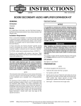
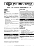
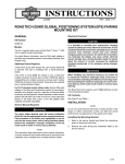
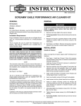
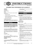
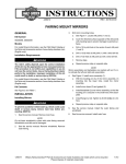
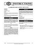
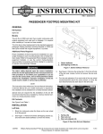
-J05872
REV. 2013-10-10
ILLUMINATED CHROME COVER KIT FOR FAIRING MOUNT MIRRORS
The Illuminated Chrome Mirror Cover Kit requires up to 100
mA additional current from the electrical system.
GENERAL
Kit Number
Kit Contents
56000084
See Figure 3 and Table 1.
Models
For model fitment information, see the P&A Retail Catalog or
the Parts and Accessories section of www.harley-davidson.com
(English only).
INSTALLATION
Preparation
Models with main fuse:
NOTES
The mirror covers in this kit are not intended to replace the
stock turn signals. Mirror cover turn signals will not function
properly without the stock turn signals installed.
Tools and Supplies Required
To prevent accidental vehicle start-up, which could cause
death or serious injury, remove main fuse before proceeding. (00251b)
1.
See the service manual. Remove main fuse.
Installation
The rider's safety depends upon the correct installation
of this kit. Use the appropriate service manual procedures.
If the procedure is not within your capabilities or you do
not have the correct tools, have a Harley-Davidson dealer
perform the installation. Improper installation of this kit
could result in death or serious injury. (00333a)
1.
See the service manual. Remove outer fairing.
2.
See Figure 1. Remove the mirrors (1), flange nuts (3) and
plastic backing plates (2) securing the mirrors to each side
of the inner fairing. Retain all items.
3.
Measure 1 in (25 mm) outboard (4) from the large mirror
stud hole in the inner fairing, and make a mark.
4.
Drill a 1/4 inch (6 mm) diameter hole through the inner
fairing at the mark.
5.
Repeat Steps 3 and 4 for opposite side.
NOTE
This instruction sheet refers to service manual information. A
service manual for this year/model motorcycle is required for
this installation and is available from a Harley-Davidson dealer.
Electrical Overload
It is possible to overload your vehicle's charging system
by adding too many electrical accessories. If the combined
electrical accessories operating at any one time consume
more electrical current than the vehicle's charging system
can produce, the electrical consumption can discharge
the battery and cause damage to the vehicle's electrical
system. See an authorized Harley-Davidson dealer for
advice about the amount of current consumed by additional electrical accessories or for necessary wiring
changes. (00211c)
NOTE
Make sure ambient temperature is at least 50 °F (10 °C) for
proper adhesion of the mirror cover to the mirror.
6.
Clean the back surface of the mirrors with the alcohol pad
provided. Allow to dry completely.
7.
Obtain the primer tube from the kit, and follow the
instructions on the tube to activate the primer. When the
primer is activated apply the primer to the back surface of
one mirror.
When installing any electrical accessory, be certain not
to exceed the maximum amperage rating of the fuse or
circuit breaker protecting the affected circuit being modified. Exceeding the maximum amperage can lead to electrical failures, which could result in death or serious injury.
(00310a)
-J05872
Many Harley-Davidson® Parts & Accessories are made of plastics and metals which can be recycled.
Please dispose of materials responsibly.
1 of 4
Electrical Connections
is07561a
6
4
2
1
5
7
1.
See the service manual. Remove turn signal bracket
assembly.
2.
See Figure 2. Locate and disconnect turn signal connector
(2) from turn signal harness connector [31L or 31R](1).
3.
Route the wires of the mirror cover down to the turn signal
connector. Secure the mirror cover wires with cable straps.
4.
Install the Y-harness (3) to each of the turn signal harness
connector.
5.
See the service manual connector appendix. Install the
pins of the mirror cover wires to the connector housing
(Figure 3, item 6). Install the wires into the housing so that
wires will connect to the same color wire on the Y-harness.
6.
See Figure 2. Connect the mirror cover connector to the
Y-harness (3).
7.
See the service manual. Connect the turn signal connector
(2) to the Y-harness, then install turn signal bracket
assembly.
8.
Repeat the procedure for the opposite side mirror cover.
3
1.
2.
3.
4.
5.
6.
7.
Mirror assembly
Backing plate
Flange nut
Hole location
Mirror cover
Grommet
Mirror cover wire
Figure 1. Mirror Cover Installation
is07679
NOTE
The Illuminated Chrome Mirror Covers are side-specific. The
covers install with the wire harness exiting from the bottom.
8.
9.
Obtain the correct mirror cover from the kit. Rub the liners
on the three pads on the back surface of the mirror cover
to activate the adhesive. Then remove the liners.
Place the mirror cover over the back surface of the mirror
and press into place for a minimum of 60 seconds.
3
4
1
2
10. Repeat Steps 7 through 9 for the remaining mirror and
cover.
11. Position the mirror on the outer face of the inner fairing,
with the rounded side of the mirror outboard.
a.
See Figure 1. Insert the mirror cover wire (7) through
the drilled hole (4).
b.
Secure wiring grommet (6) in drilled hole.
c.
Insert the mirror post through the original mirror
mounting hole.
d.
Install backing plate over mirror assembly. Make sure
the locating pin is secured in the small hole of the
backing plate.
e.
Install flange nut. Tighten to 20-30 in-lbs (2.3-3.4
Nm).
f.
Repeat steps for the opposite side.
-J05872
1.
2.
3.
4.
Turn signal harness connector, female
Turn signal connector, male
Y-harness
Mirror cover connector
Figure 2. Auxiliary/Fog Lamp Assembly
2 of 4
Proper operation of mirror cover lamps is:
FINAL ASSEMBLY
1.
Secure all wiring away from any moving parts, pinch points
or extreme heat.
NOTE
Verify that the ignition/light key switch is in the OFF position
before installing the main fuse/attaching the battery cables.
2.
See the service manual. Install main fuse.
3.
Turn the ignition/light key switch to IGNITION, but do not
start the motorcycle. Test for proper turn signal and mirror
cover lamp operation.
-J05872
4.
a.
Mirror cover lamps are not lit during normal vehicle
operation.
b.
The proper mirror cover lamp flashes along with the
corresponding turn signal when activated.
c.
BOTH mirror cover lamps flash when the emergency
flashers are activated.
See the service manual. Install outer fairing.
Adjust the mirrors for proper field of vision and compliance
with local regulations.
3 of 4
SERVICE PARTS
is07668
1
2
5
11 10
9
5
8
6
3
4
10 11
7
Figure 3. Service Parts: Illuminated Fairing Mounted Mirror Cover Kit
Table 1. Service Parts Table
Item
Description (Quantity)
Part Number
1
Mirror cover, right
Not Sold Separately
2
Mirror cover, left
Not Sold Separately
3
Grommet (2)
Not Sold Separately
4
Terminal, pin, #20-22 AWG (6)
72910-11
5
Seal, pin (6)
5118
6
Housing, 4-way, pin, JAE (2)
72908-11
7
Y-harness (2)
69200880
8
•
Housing, 4-way, socket, JAE
72908-11
9
•
Terminal, socket, #20-22 AWG
72910-11
10 •
Housing, 4-way, pin, JAE (2)
72907-11
11 •
Terminal, pin, #20-22 AWG
72909-11
12 Alcohol packet (not shown)
Not Sold Separately
13 Primer packet (not shown)
Not Sold Separately
-J05872
4 of 4