1
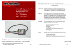
FORM #33001.06-121703 PRINTED IN U.S.A. PAGE 2 OF 11 PARTS LIST … The part number is printed on an adhesive label. Identify each part and place the appropriate mounting hardware with it. PART NO DESCRIPTION NEW ATTACHING HARDWARE (Qty.- if more than one) (Quantity) 33001 ..........................TruSpeed calibrator ..................... (2) non-insulated butt connectors (2) length 1/8” heat shrink tubing (1) #8 ring terminal (1) fuse tap, standard blade (1) fuse tap, mini-blade (1) spade terminal, .210” blade (1) spade terminal, .110” blade (1) calibrator key (4) 3” tie wraps (1) strip Velcro tape 00465 ...........................decal, "Notification To Driver" GENERAL INFORMATION The procedure below details installing and calibrating the TruSpeed module. Because some installers may be unfamiliar with electrical work, it may be helpful to have a brief overview of how the TruSpeed module works and is installed. Speed sensors emit a pulse that is sent to various vehicle systems for processing. This pulse, or signal, is set by the OE manufacturer and is nonadjustable, so installing larger tires and / or changing gear ratios will cause inaccurate speed readings. The TruSpeed module basically makes this pulse adjustable. It installs in-line with the speed signal wire, so the speed signal must now pass through the TruSpeed module to get to its destination. It takes the original signal (from the speed sensor) that is no longer accurate (due to tire or gear changes) and alters it into the correct one for the tire and / or gear combination. The degree of signal alteration depends on how the module is calibrated. The TruSpeed installation involves locating proper speed signal wire, cutting it, splicing in the TruSpeed wires, and providing power to the module. The module mounts inside the cab of the vehicle and requires a simple four wire hookup: the red wire connects to a positive 12-volt source and the black wire connects to a good ground. After the speed signal wire is cut, the green wire connects to one end of the signal wire and the yellow wire hooks to the other end of the signal wire. All of this is described in detail below. Read through the entire procedure before beginning to familiarize yourself with the procedure prior to beginning the installation. If you feel uncomfortable with the installation, contact Superlift or consult an expert in automotive electrical systems. INSTALLATION PRODEDURE 1) PREPARE VEHICLE... The vehicle should be in Park or First gear with the ignition in the “off” position.