1
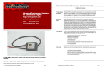
FORM #33001.06-121703 PRINTED IN U.S.A. PAGE 3 OF 11 2) POWER CONNECTIONS… NOTE: Be sure to route all wires away from sharp edges and high heat sources. As a general rule, it is best to route all wires by following a factory wire loom whenever possible. Find a suitable location inside the cab to mount the TruSpeed module. The module is water resistant, but it should be installed away from high heat sources such as the heating ducts and vents. In most instances, it can easily be attached to the bottom of the dash using the supplied Velcro. Separate the red and black wires from the yellow and green wires on the TruSpeed module. Using the supplied ring terminal, route and attach the black wire from the module to a suitable ground. Trim the wire to length as necessary. Locate the fuse block for the vehicle. Fuse block location can be found in the vehicle owner’s manual or service manual. Refer to chart “A” to identify an appropriate switched 12-volt source on the fuse block for your application. The circuit should be hot when the ignition switch is in both the “start” and “run” positions. Use the fuse puller tool (normally attached to the fuse block or the access door) to pull the fuse indicated in the chart out of the block and set aside. Turn the ignition switch to the “on” position. Using a test light or voltmeter, determine which side of the fuse terminal (where you just removed the fuse) is “hot,” or receiving 12 volts. Turn the ignition switch back to the “off” position. Slide the appropriate fuse tapper into the hot side of the circuit (two are provided with the module: one for standard blade-type fuses and one for mini-blade fuses used in most late-model vehicles) and replace the fuse. Disconnect the negative battery cable from the battery. Trim the red wire from the TruSpeed module as necessary, attach the supplied spade terminal, and connect it to the fuse tapper.