1
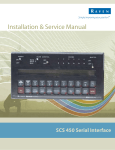
Installation & Service Manual
Accu-Flow
DISCLAIMER
While every effort has been made to ensure the accuracy of this document, Raven
Industries assumes no responsibility for omissions and errors. Neither is any liability
assumed for damages resulting from the use of information contained herein.
Raven Industries shall not be held responsible or liable for the effects of atmospheric
conditions and sunspot activity on the performance of our products.
Raven Industries cannot guarantee the accuracy, integrity, continuity, or availability of
the GPS signal from the US Department of Defense/NAVSTAR GPS satellites, the
OmniSTAR correction service or the WAAS correction service.
Raven Industries accepts no responsibility for the use of the signal for other than the
stated purpose. Raven Industries shall not be responsible or liable for incidental or
consequential damages or a loss of anticipated benefits or profits, work stoppage or
loss or impairment of data arising out of the use or inability to use the Smartrax or any
of its components.
Manual # 016-0159-403
Table of Contents
Symbol Definition ............................................................................................................. 2
Chapter 1 - Introduction ................................................................................................ 3
Chapter 2 - Installation .................................................................................................. 5
Assembly of the Accu-Flow System ....................................................................... 5
Mounting of Accu-Flow System on Implement ........................................................ 6
Mounting the Manifold ............................................................................................ 7
Final Plumbing of Accu-Flow System ..................................................................... 8
Mounting Wheel Drive Speed Sensor .................................................................. 10
Mounting the Console and Cabling ...................................................................... 10
Chapter 3 - Calculation and Operation ....................................................................... 11
Battery Connections ............................................................................................ 11
Console Features ................................................................................................ 11
Console Calibration ............................................................................................. 11
Calculating “BOOM CAL” .......................................................................... 12
Calculating “SPEED CAL” ......................................................................... 12
Calculating “METER CAL” ......................................................................... 12
Calculating “VALVE CAL” ......................................................................... 12
Calculating “REQUIRED CAPACITY”......................................................... 13
Console Programming ........................................................................................ 13
Pre-Operational Check-Out ................................................................................. 14
Operational Check-Out ........................................................................................ 15
Chapter 4 - Troubleshooting....................................................................................... 17
APPENDICES
A.
B.
C.
D.
E.
F.
Pressure-Temperature Chart ............................................................................... 21
Accu-Flow Super Cooler ..................................................................................... 23
Accu-Flow Troubleshooting Procedure ................................................................ 27
System Capacity Chart ........................................................................................ 29
Recommended Emergency Shut-Off Rope Installation ......................................... 31
Flowmeter Maintenance and Adjustment Procedure ............................................ 33
30 GPM Accu-Flow System On/Off Control Valve Replacement Parts ............................. 35
30 GPM Accu-Flow System Fast Valve Replacement Parts ............................................ 36
System Diagrams........................................................................................................................37
1
Accu-Flow Manual
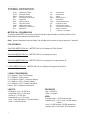
SYMBOL DEFINITION
GPM
lit/min
dl/min
PSI
kPa
GPA
lit/ha
ml/ha
GPK
mm
- Gallons per minute
- Liters per minute
- Deciliter per minute
- Pounds per square inch
- Kilopascal
- Gallon per acre
- Liter per hectare
- Mililiter per hectare
- Gallons per 1,000 sq. ft.
- Millimeters
cm
dm
m
MPH
km
km/h
US
SI
TU
[]
{}
- Centimeters
- Decimeters
- Meter
- Miles per hour
- Kilometers
- Kilometers per hour
- Volume per acre
- Volume per hectare
- Volume per 1,000 sq. ft.
- Metric numbers
- 1,000 sq. ft. numbers
METER CAL CONVERSIONS
To convert the METER CAL number, simply divide the original number (number printed on Flow
Meter label) by the desired conversion factor.
Note: Newer flowmeters have the Meter Cal included on the meter cal tag for pounds of actual N.
FOR EXAMPLE:
GALLONS METER CAL No. = METER CAL No. for displays in Fluid Ounces
128
GALLONS METER CAL No. = METER CAL No. for displays in Liters
3.785
GALLONS METER CAL No. = METER CAL No. for displays in Pounds of actual N
4.22
LITERS METER CAL No. = METER CAL No. for displays in kilograms of actual N.
.506
LIQUID CONVERSIONS
U.S. Gallons x 128 = Fluid Ounces
U.S. Gallons x 3.785 = Liters
U.S. Gallons x 0.83267 = Imperial Gallons
U.S. Gallons x 8.34 = Pounds (Water)
U.S. Gallons x 4.22 = Pounds of Actual N
Liters x .506 = Kilograms of Actual N
LENGTH
PRESSURE
1 millimeter (mm) = 0.039 inch
1 centimeter (cm) = 0.393 inch
1 meter (m) = 3.281 feet
1 kilometer (km) = 0.621 mile
1 inch = 25.4 millimeters; 2.54 centimeters
1 mile = 1.609 kilometers
1 psi = 6.89 kPa
1 kPa = 0.145 psi
2
AREA
1 square meter = 10.764 square feet
1 hectare (ha) = 2.471 acres; 10,000 square
meters
1 acre = 0.405 hectare; 43,560 square feet
1 square mile = 640 acres; 258.9 hectares
Manual # 016-0159-403
C HAPT E R
1
INTRODUCTION
The Raven ACCU-FLOW system is designed to work in conjunction with
Raven SCS Consoles to provide automatic control of anhydrous ammonia
applications. Unlike conventional systems on the market, the ACCU-FLOW
system provides continuous and automatic control of anhydrous ammonia
regardless of tank pressure, outside temperature, or vehicle speed. Just set
the application rate and the Console does the rest.
The ACCU-FLOW system is a complete unit ready to be mounted to your tool
bar or field cultivator.
3
Accu-Flow Manual
Notes:
4
Manual # 016-0159-403
C HAPT E R
2
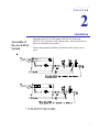
Installation
Assembly of
the Accu-Flow
System
Assembly the ACCU-FLOW system (P/N 063-0172-991 and
063-0171-157) as shown in the Figures below. All nuts and bolts required for assembly are included.
Use the teflon gasket provided to eliminate possible leaks in the 1”
union.
5
Accu-Flow Manual
Mounting of
Accu-Flow
System on
Implement
The ACCU-FLOW system is mounted directly on the frame of the tool
bar or implement as shown in the figure below. Use u-bolts provided for
mounting.
MOUNTING OF ACCU-FLOW SYSTEM ON IMPLEMENT
MOUNT ACCU-FLOW SYSTEM TO
IMPLEMENT WITH COOLER INLET
POINTING TOWARD NURSE TANK
(REAR OF IMPLEMENT)
6
Manual # 016-0159-403
Mounting the
Manifold
See figures below for various ways to attach your existing manifold(s).
(Manifold not included) Attach a 0-60 PSI gauge in one outlet of each
manifold. Verify that all hose barbs in manifold(s) have same orifice
diameter.
7
Accu-Flow Manual
Final
Plumbing of
Accu-Flow
System
To complete the plumbing of the ACCU-FLOW system, proceed as
follows:
1.
Weld the two steel Vapor Tubes provided in the ACCU-FLOW kit
to the two center applicator knives as shown in top figure on
page 9.
2.
Install Flow Meter (RFM 60S) and Control Valve.
Helpful Hint: The ON/OFF Valve is not used if a Fast
Control Valve is installed.
The Plastic motorized Control Valve used on a liquid
system can not be used with NH3. You must use the
specially designed motorized Control Valve. This special
NH3 Valve can also be used with all other chemicals;
i.e. herbicides, insecticides, and liquid fertilizer.
3.
Connect the two 3/4” I.D. vapor hoses to the hose barbs in the
sides of the Heat Exchanger. Connect the two hoses to the two
steel vapor tubes.
4.
Install the 3/8” I.D. Heat Exchanger hose from the hose barb
outlet on the end of the system, to the inlet at the bottom of the
Heat Exchanger. The function of the Heat Exchanger is to
eliminate vapor and to provide liquid ammonia to the Flow Meter
so that it can be accurately measured.
5.
Verify that all of the orifice openings in the liquid applicator tubes
are unplugged and of the same diameter.
6.
Verify that all of the applicator hoses are of equal length from
each manifold hose barb to each liquid applicator tube.
7.
For high flow systems (20 GPM or greater), it is essential that:
a)
1 1/4” hose is used between the nurse tank and
emergency shut-off valve.
b)
The 1 1/4” hose must be as short as possible (less than
15 feet).
c)
A 1 1/4” break-away coupler must be installed.
A high flow tank valve is also recommended. Do not use street
elbows (due to excessive pressure drop).
See Figure on page 9 for example.
8
Manual # 016-0159-403
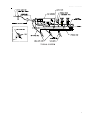
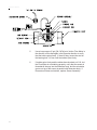
TYPICAL SYSTEM
9
Accu-Flow Manual
Mounting the
Wheel Drive
Speed Sensor
Mounting the
Console and
Cabling
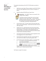
Reference associated SCS Console INSTALLATION AND SERVICE
MANUAL.
Reference associated SCS Console INSTALLATION AND SERVICE
MANUAL.
Important: Since the Raven ACCU-FLOW is capable of
being installed in conjunction with several different SCS
Consoles, it is necessary to make referrals to the
appropriate SCS Console Installation and Service Manual.
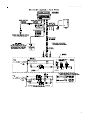
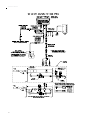
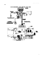
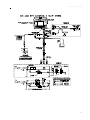
Note: Refer to pages 37- 44 for specific system cable
diagrams.
10
Manual # 016-0159-403
C HAPT E R
3
CALCULATION AND OPERATION
Important: Since the Raven ACCU-FLOW is capable of
being installed in conjunction with several different SCS
Consoles, it is necessary to make referrals to the
appropriate SCS Console Installation and Service Manual.
The following will detail these headlines that can be
located in the TABLE OF CONTENTS of the appropriate
Installation and Service Manual.
Battery
Connections
Reference associated SCS Console INSTALLATION AND SERVICE
MANUAL.
Console
Features
Reference associated SCS Console INSTALLATION AND SERVICE
MANUAL.
Console
Calibration
Reference associated SCS Console INSTALLATION AND SERVICE
MANUAL.
11
Accu-Flow Manual
Calculating “BOOM CAL”
Reference associated SCS Console INSTALLATION AND SERVICE
MANUAL.
Implement width = Number of applicators knives x Spacing in inches
[cm].
Calculating “SPEED CAL”
Reference associated SCS Console INSTALLATION AND SERVICE
MANUAL.
Calculating “METER CAL”
To display application rate in pounds per acre of actual N (PPAN), or
kilograms per hectare of actual N [KgPh], divide original METER CAL by
4.22 [.506], and use the figure obtained as new METER CAL number.
You must round to the nearest 3 digit whole number.
EXAMPLE: Assume METER CAL number is 720 [190].
Pounds:
Adjusted Meter Cal = 720 = 170.6
4.22
Kilograms:
Adjusted Meter Cal = 190=375.5
.506
The number to enter for the METER CAL is 171 [375]. Enter target
application rate in pounds per acre of actual N (PPAN), or kilograms per
hectare of actual N [KgPh].
Important: All volumes will be displayed in Pounds (Kg)
of Actual N.
Calculating “VALVE CAL”
Reference associated SCS Console INSTALLATION AND SERVICE
MANUAL.
Note: Valve CAL number may need an adjustment to
obtain control particularly at low flow rates.
12
Manual # 016-0159-403
Calculating “REQUIRED CAPACITY”
The target application rate which you program into the SCS Console is
in “Pounds Per Acre of Actual N (PPAN)”, as is most often associated
with NH3.
After determining the PPAN application rate, calculate the total pounds
per minute of actual N (PPMN) flow of the system to ensure that the
system capacity is not exceeded. To make this calculation, use the
following formula:
PPMN [KPMN]=PPAN [KgPh] x MPH [KPH] x Implement Width (inches) [cm]
(5,940) [60,000]
PPAN [KgPh]
MPH [KPH]
Implement Width
PPMN
= Target Application Rate
= Target Vehicle Speed
= Number of Applicator Knives x Spacing (in inches)
= Required Capacity of the System
EXAMPLE:
ENGLISH UNITS:
PPMN = 150 x 5.5 x 480 = 66.6
(5,940)
METRIC UNITS:
KPMN = [68] x [10] x [1220] = 13.8
[60,000]
PPMN = 67 Pounds Per Minute
KPMN = 14 Kilograms Per Minute
The maximum capacity of the 30 GPM system is 126 PPMN [57 KPMN].
Consult factory if maximum rate is exceeded.
Console
Programming
Reference associated SCS Console INSTALLATION AND SERVICE
MANUAL.
13
Accu-Flow Manual
PreOperational
Check-Out
Complete the following pre-operational check-out before proceeding:
1.
Verify that all hoses, fittings, and mounting bolts are secure.
2.
Verify that the SCS Cable Assembly is attached to the connector
on the Flow Meter.
3.
Verify that the SCS Cable Assembly is attached to the motorized
Control Valve connector.
4.
Turn Console MASTER switch OFF.
5.
Open completely the Emergency Shut-Off Valve.
6.
Close all bleed ports.
7.
Connect and secure nurse tank hose to implement.
8.
Open slightly the nurse tank shut-off valve.
9.
Inspect the system for leaks. If none, proceed to Step 11.
10.
If leaks are present, close the nurse tank shut-off valve. Open
bleed port (Refer to Typical System figure on page 9) to exhaust
all NH3 in the lines. Allow at least 30 minutes for system to bleed
off. The cooler should not feel cold. Verify that the pressure
gauge reading on the ACCU-FLOW system is zero. After all
lines have been completely exhausted, disconnect nurse tank
hose (USE CAUTION). Correct leaks and repeat Steps 7 thru
10.
11.
Verify that the pressure gauge reading (if installed) on the
ACCU-FLOW system compares to that on the nurse tank. If
not, one of the gauges is defective and should be replaced.
12.
Fully open nurse tank shut-off valve.
IMPORTANT: REVIEW THE SAFETY REQUIREMENTS
ASSOCIATED WITH THE HANDLING AND APPLICATION
OF ANHYDROUS AMMONIA WITH YOUR LOCAL NH3
SUPPLIER.
14
Manual # 016-0159-403
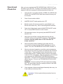
Operational
Check-Out
After you have completed the PRE-OPERATIONAL CHECK-OUT, you
are ready to go to the field. To quickly verify that the system is working
properly in the field, complete the following operational check-out:
1.
Verify that the correct Boom Widths, SPEED CAL, METER CAL,
VALVE CAL, and RATE CALS have been entered correctly into
the Console.
2.
Place Console switch to MAN.
3.
MASTER ON/OFF switch positioned to OFF.
4.
BOOM 1 switch ON (if dual manifold is used, BOOM 1 and
BOOM 2 should be ON). Shut off remaining BOOM switches.
5.
Drive down field at target speed with MASTER ON/OFF switch
OFF to verify SPEED read-out on the Console.
6.
With applicator knives in the ground, place MASTER ON/OFF
switch to ON.
7.
While driving in the field, manually adjust the flow with the
INC/DEC switch until target RATE is obtained. The manifold
pressure must be greater than 10 PSI at this time for
proper operation.
8.
Select automatic mode of operation, the system will now
automatically maintain the target RATE regardless of vehicle
speed. If not, see TROUBLESHOOTING GUIDE, Problem 12.
9.
After two minutes of operation, record the system temperature
and pressure from the two gauges mounted near the motorized
Control Valve. These readings must be obtained while you are
actually apply the NH3. Readings will be incorrect if the system
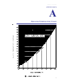
is shut off, even momentarily. Find the intersection point of these
two readings on the PRESSURE-TEMPERATURE chart in
Appendix A. This point must be located in the NON-VAPOR area
(above the line). If it is not, see TROUBLESHOOTING GUIDE,
Problem 17.
EXAMPLE: Pressure reading 70 PSI and temperature reading
40 F. The point where these two readings intersect is the NONVAPOR area. See Appendix A.
10.
Clean magnets in Strainer and Magnet Assembly after every 4 or
5 tank loads (at minimum) of NH3.
Important: Perform system bleed procedure found on
page 24.
15
Accu-Flow Manual
11.
16
If an additive such as N-Serve (Dow Chemical), or ACA (Amoco)
is used, it may require periodic cleaning of the Flowmeter by
disassembling the Flowmeter. See Appendix F.
Manual # 016-0159-403
C HAPT E R
4
TROUBLESHOOTING
Problem 1: No display lights with power ON.
Solutions:
1.
Check fuse on back of Console.
2.
Check battery connections.
3.
Check operation of POWER ON/OFF switch.
4.
Return Console to your Dealer to replace Processor Board
Assembly.
Problem 2: All keyboard lights on at same time.
Solution:
1.
Return Console to your Dealer to replace Face Plate
Subassembly.
Problem 3: A digit cannot be entered via keyboard.
Solution:
1.
Return Console to your Dealer to replace Face Plate
Subassembly.
Problem 4: An indicator light on a key will not illuminate.
Solution:
1.
Return Console to your Dealer to replace Face Plate
Subassembly and/or Processor Board Assembly.
Problem 5: Console displays flashing “CAL” whenever vehicle engine
is started.
Solution:
1.
Check battery voltage and battery connections.
17
Accu-Flow Manual
Problem 6: Console displays flashing “CAL” whenever master switch
is turned ON or OFF.
Solution:
1.
Check battery voltage and battery connections.
Problem 7: “TIME” function is inaccurate or drifting.
Solution:
1.
Return Console to Dealer to replace Processor Board Assembly.
Problem 8: One display digit has one or more missing segments.
Solution:
1.
Return Console to Dealer to replace LCD Display Board
Assembly.
Problem 9: Speed display “0”.
Solutions:
1.
Check Speed Sensor Cable connector and plug on back of
Console for loose pins.
2.
Clean pins and sockets on Speed Sensor cable connectors.
3.
If no extension cable is used, replace Speed Sensor Switch
Assembly.
Problem 10: Speed inaccurate or unstable (Wheel Drive Speed
Sensor).
Solutions:
1.
Run speed check on hard surface road. If SPEED is accurate,
investigate mounting Speed Sensor on different wheel.
2.
Remove one red magnet and one black magnet from the wheel.
(Reposition remaining red and black magnets directly across
from each other). Enter a SPEED CAL number in the Console
twice as large as the correct SPEED CAL number. Run speed
check on hard surface road. Remove these two magnets and
replace with other two. Run speed check. If SPEED is
inaccurate with only one set of magnets, replace the bad set. If
SPEED is inaccurate with both sets, replace Speed Sensor
Assembly.
NOTE: Re-enter original SPEED CAL number after testing is
complete.
18
Console
Manual # 016-0159-403
Problem 11: Rate Reads “0000”.
Solutions:
1.
Verify SPEED is registering accurately. If SPEED is zero, refer
to Troubleshooting Problem 10.
2.
Verify TOTAL VOLUME is registering flow. If not, refer to
Troubleshooting Problem 14.
Problem 12: Rate inaccurate or unstable.
Solutions:
1.
Verify that all numbers “keyed in” Console are correct. Verify
SPEED is registering accurately. If SPEED is inaccurate, refer
to Troubleshooting Problem 10.
2.
In MAN (manual) operation, verify that RATE display holds
constant. If not, refer to Troubleshooting Problem 17.
3.
Verify plumbing with a maximum of 15’ of 1 1/4” hoses and 1 1/4”
breakaway.
Important: Perform system bleed procedure prior to
maintenance (see page 24).
4.
5.
Remove any street elbows and replace with a conventional
elbow and nipple.
Verify that the tank has a high flow valve.
Problem 13: Cannot vary rate in manual operation or in AUTO.
Solutions:
1.
Check cabling to motorized Control Valve for breaks.
2.
Check connections in cabling for cleanliness.
3.
Verify that there is voltage at the valve connector by placing
MASTER switch ON; RATE 1/RATE 2/MAN switch to MAN; and
POWER switch to ON. Manually operate INC/DEC switch to
verify voltage.
4.
Verify that valve is turning by looking at coupler shaft. If not,
replace control valve motor.
CAUTION: Bleed system thoroughly prior to disassembling of
system.
Problem 14: Total Volume does not register.
Solutions:
1.
Check Flow Meter cable for breaks and shorts. See Console
Installation Manual for test procedure.
2.
Check internals of Flow Meter; clean and adjust. See Console
Installation Manual for Flow Meter cleaning and adjustment.
Important: Perform system bleed procedure prior to
maintenance (see page 24).
19
Accu-Flow Manual
Problem 15: Total Volume Registers Flow Inaccurately.
Solutions:
1.
Verify that arrow on Flow Meter is pointing in direction of flow.
2.
Clean Flow Meter according to Appendix F.
3.
See Appendix in Console Installation Manual.
Problem 16: Motorized Control Valve rotates more than 1/4 turn.
Solution:
1.
Replace motorized Control Valve.
Problem 17: Pressure vs. Temp. operating point located in the vapor
area chart.
Solutions:
1.
Verify that the vapor tubes have been affixed to the applicator
knives correctly and that their openings are not plugged.
2.
Disassemble and clean Heat Exchanger if additives such as
N-Serve or ACA are being used. See Appendix B.
3.
Determine if pressure drop is within limits. See Appendix C.
20
Manual # 016-0159-403
APPENDIX
A
PRESSURE-TEMPERATURE CHART
21
Accu-Flow Manual
Notes:
22
Manual # 016-0159-403
APPENDIX
B
ACCU-FLOW SUPER COOLER
063-0172-877 (30 GPM)
ITEM
1
2
3
4
5
6
DESCRIPTION
Relief Valve
Outer Assembly (30 GPM)
O-Ring
Inner Assembly (30 GPM)
Gasket
3/8”-16 Hex Nut
PART #
334-0002-005
116-0159-683
219-0000-036
116-0159-430
219-0000-143
312-1001-037
Note: Accuflow super cooler of (P/N 063-0159-837 and
063-0159-546), use Gasket Retainer Kit 117-0171-121.
Gaskets only (P/N 219-0000-142C and 219-0000-144).
23
Accu-Flow Manual
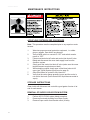
MAINTENANCE INSTRUCTIONS
ACCUFLOW SYSTEM BLEED PROCEDURE
Note: This procedure must be completed prior to any repairs or maintenance.
1.
2.
3.
4.
5.
6.
7.
8.
Wear/use proper personal protective equipment, i.e. rubber
gloves, goggles, face shield, long sleeves.
Verify master switch on console is ‘OFF’ and switch console
power to ‘OFF’.
Close nurse tank shut-off valve and cooler inlet shut-off valve.
Bleed and disconnect the nurse tank supply hose from the
Accuflow system.
Slowly open the cooler inlet shut-off valve (make sure the nurse
tank disconnect coupler does not leak).
While standing upwind, slowly open cooler bleed valve to full
open (see Typical System figure found on page 9).
Allow 60 minutes for system to fully bleed out.
Verify that the cooler gauge pressure is zero and the cooler is
not cold to the touch (insure that all NH3 liquid has converted to
vapor).
STORAGE INSTRUCTIONS
Clean inside with Kerosene and coat with a good grade of motor oil at
end of each season.
REMOVAL OF SUPER COOLER FROM SYSTEM
1.
2.
3.
24
Perform ACCU-FLOW system bleed procedure.
Remove all external plumbing from Super Cooler.
Remove Super cooler from bracket mount (4 bolts).
Manual # 016-0159-403
DISASSEMBLY/ASSEMBLY OF SUPER COOLER
1.
2.
3.
4.
5.
6.
Clamp Super Cooler in vise with relief valve up.
Remove four (4) bolts from base.
Remove Inner Assembly with a twist-pull motion. Use
CAUTION, DO NOT FORCE.
Clean residue from Inner Assembly and inspect Outer Assembly.
Replace two (2) O-Rings. Lubricate O-Rings with brake fluid
when installing and reassembling.
Assemble in reverse order.
25
Accu-Flow Manual
Notes:
26
Manual # 016-0159-403
APPENDIX
C
ACCU-FLOW TROUBLESHOOTING PROCEDURE
Problem: Inaccurate measurements
(System indicates more than the amount removed from tank)
1.
Record operating temperature, operating pressure, and static
tank pressure from Temperature and Pressure gauges on
ACCU-FLOW. See page 9 for location of gauges.
2.
Verify that operating temperatures and pressure point lies to the
left of operating curve. See Pressure-Temperature Chart,
Appendix A. If to the left of operating curve, clean Flow Meter
and check cables and proceed to Step 4. If not, proceed to Step
3.
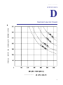
3.
Operating temperature and pressure point lies on the operating
curve of the Pressure-Temperature Chart, see System Capacity
Chart, Appendix D, to determine the maximum speed allowance
for application. If maximum speed is exceeded, reduce speed,
if not, proceed with Step 5.
4.
Review plumbing of system per recommended procedure (see
figure on page 9). If not similar to drawing, re-plumb system. If
plumbed correct, proceed to Step 5.
5.
Using the static pressure and operating pressure reading
obtained in Step 1, verify that the difference does not exceed 5
PSI. If greater than 5 PSI, proceed with Step 6, if not, proceed
with Step 7.
6.
Clean strainer next to the Heat Exchanger. Check hoses for
deterioration, replace if necessary. Remove all excess hose
length between tank and break-away coupler, (typically 12 feet),
also excess hose between break-away coupler and system,
(typically 3 feet). Verify that break-away coupler is 1 1/4”, not 1”.
If correct, proceed to Step 7.
27
Accu-Flow Manual
7.
28
Check Heat Exchanger cooling chamber by removing the vapor
hoses from the steel vapor tubes at applicator knife. Secure
hose end so it can be viewed from vehicle. Drive vehicle a short
distance (1/2 minute). Verify a heavy stream of anhydrous
ammonia vapor is visible from each hose end. If not, disassemble and clean Heat Exchanger.
Manual # 016-0159-403
APPENDIX
D
SYSTEM CAPACITY CHART
29
Accu-Flow Manual
Notes:
30
Manual # 016-0159-403
APPENDIX
E
RECOMMENDED EMERGENCY SHUT-OFF
ROPE INSTALLATION
IMPORTANT: ALWAYS WORK UPWIND OF NH3
IMPLEMENT.
USE SAFETY ROPE (NOT
PROVIDED) TO SHUT OFF
HAND VALVE BETWEEN
COOLER AND NURSE
TANK.
Wind Direction
Safety Rope
31
Accu-Flow Manual
Notes:
32
Manual # 016-0159-403
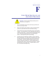
APPENDIX
F
FLOW METER MAINTENANCE AND
ADJUSTMENT PROCEDURE
Important: Perform system bleed procedure prior to
maintenance (see page 24).
1.
Remove Flow Meter from tool bar, brush away any debris and
remove any foreign material.
2.
Remove the retaining rings carefully. Remove the bearing hub,
turbine hub, and turbine from inside Flow Meter housing.
3.
Clean the turbine and hubs of metal filings and any other foreign
material. Use pressurized air to blow metal filings and debris out
of both hubs and turbine. Confirm that the turbine blades are not
worn. Hold turbine and bearing hub in your hand and spin
turbine. It should spin freely with very little drag.
4.
If bearing hub stud is adjusted or replaced, verify the turbine fit
before reassembling: Put turbine hub and retaining ring in place.
Put bearing but with turbine against turbine hub inside the flowmeter housing. (Stud keys inside flowmeter housing must be
lined up in the groove on the hub). Put the retaining ring on to
lock bearing hub in place. Spin turbine by blowing on it. Tighten
bearing hub stud until turbine stalls. Loosen the stud 1/3 of a
turn. The turbine should spin freely.
33
Accu-Flow Manual
34
5.
Use a low pressure (5 psi) [34.5 kPa] jet of air thru Flow Meter in
the direction of flow and again in the opposite direction to verify
that the turbine spins freely. If there is drag, loosen the stud on
the bearing hub 1/16 turn until the turbine spins freely.
6.
If turbine spins freely and the cables have checked out O.K., but
the Flow Meter is not totalizing properly, verify that the sensor is
threaded all the way into the flowmeter body, and the orientation
groove on top of the sensor is parallel with flowmeter body. if
flowmeter still does not totalize, replace Sensor Assembly.
Manual # 016-0159-403
30 GPM ACCU-FLOW SYSTEM
ON/OFF CONTROL VALVE REPLACEMENT PARTS
063-0172-991
** High Pressure NH3 Plumbing Should Be Done With Schedule 80 Pipe And Fittings **
ITEM
1
2
3
4
5
6
7
8
10
11
12
13
14
15
16
17
18
19
20
22
23
24
25
DESCRIPTION
Cooler Bracket
3/8"-16 x 1 3/4" Bolt
3/8" Lock Washer
3/8"-16 Hex Nut
U-Bolt Assembly
3/8" EVA Hose
Hose Clamp
Super Cooler (30 GPM)
Z-Bracket
1/2" x 3/4" Hose Barb
1 1/4" x 2" Pipe Nipple
1 1/4" x 12" Pipe Nipple
1 1/4" Elbow
3/4" EVA Hose
1/4" x 3/8" Hose Barb
1 1/2" X 1 1/4" Bushing
1 1/2" Muffler Clamp
1" Pipe Union Gasket
1" Pipe Union
1" x 2" Pipe Nipple
1" Pipe Cross
1" x 5" Pipe Nipple
1/2" x 1 1/2" Pipe Nipple
RAVEN PART #
107-0171-063
311-0054-108
313-1000-022
312-1001-037
107-0159-447
214-0001-002
435-3003-002
063-0172-877
107-0171-068
333-0002-011
333-0008-038
333-0008-044
333-0005-006
214-0001-005
333-0002-004
333-0003-019
435-3003-030
219-0000-076
333-0006-004
333-0008-029
333-0004-029
333-0008-033
333-0008-015
ITEM
26
27
28
29
30
31
32
33
34
35
36
37
38
39
40
41
42
43
44
45
46
47
DESCRIPTION
1/2" x 1/2" x 1/4" Pipe Tee
Temperature Gauge
1/4" x 2" Pipe Nipple
1/4" Pipe Tee
0-150 PSI Gauge
1/4" Bleed Valve
1" x 8" Pipe Nipple
1" Pipe Cap
1/2" x 1/4" Pipe Elbow
1/2" x 2" Pipe Nipple
1" x 1/2" Pipe Elbow
1" Pipe Tee
Control Valve
On/Off Valve
1 1/4" Y-Strainer
1 1/4" Steel Ball Valve
Ceramic Magnets
Flow Meter, 60S
1" x 1/2" Reducing Bushing
1" x 3" Pipe Nipple
Vapor Tubes (Not Shown)
1 1/2" x 1" Bushing
RAVEN PART #
333-0004-009
417-0001-009
333-0008-002
333-0004-001
417-0001-008
334-0001-012
333-0008-034
333-0009-090
333-0005-009
333-0008-016
333-0005-010
333-0004-005
063-0172-977
063-0172-978
333-9000-025
019-0159-245
418-0000-001
063-0171-666
333-0003-094
333-0008-031
214-0002-002
333-0003-020
054-0159-117
35
Accu-Flow Manual
30 GPM ACCU-FLOW SYSTEM
FAST VALVE REPLACEMENT PARTS
063-0171-157
** High Pressure NH3 Plumbing Should Be Done With Schedule 80 Pipe And Fittings **
ITEM
1
2
3
4
5
6
7
8
10
11
12
13
14
15
16
17
18
19
20
22
23
24
25
DESCRIPTION
Cooler Bracket
3/8"-16 x 1 1/4" Bolt
3/8" Lock Washer
3/8"-16 Hex Nut
U-Bolt Assembly
3/8" EVA Hose
Hose Clamp
Super Cooler (30 GPM)
Z-Bracket
1/2" x 3/4" Hose Barb
1 1/4" x 2" Pipe Nipple
1 1/4" x 12" Pipe Nipple
1 1/4" Elbow
3/4" EVA Hose
1/4" x 3/8" Hose Barb
1 1/2" x 1 1/4" Bushing
1 1/2" Muffler Clamp
1" Pipe Union Gasket
1" Pipe Union
1" x 2" Pipe Nipple
1" Pipe Cross
1" x 5" Pipe Nipple
1/2" x 1 1/2" Pipe Nipple
054-0159-118
36
RAVEN PART #
107-0171-063
311-0054-106
313-1000-022
312-1001-037
107-0159-447
214-0001-002
435-3003-002
063-0172-877
107-0171-068
333-0002-011
333-0008-038
333-0008-044
333-0005-006
214-0001-005
333-0002-004
333-0003-019
435-3003-030
219-0000-076
333-0006-004
333-0008-029
333-0004-029
333-0008-033
333-0008-015
ITEM
26
27
28
29
30
31
32
33
35
36
37
38
39
41
42
43
44
45
46
47
DESCRIPTION
1/2" x 1/2" x 1/4" Pipe Tee
Temperature Gauge
1/4" x 2" Pipe Nipple
1/4" Pipe Tee
0-150 PSI Gauge
1/4" Bleed Valve
1" x 8" Pipe Nipple
1" Pipe Cap
1/2" x 2" Pipe Nipple
1" x 1/2" Pipe Elbow
1" Pipe Tee
Fast Valve
1 1/4" Y-Strainer
1 1/4" Steel Ball Valve
Ceramic Magnets
Flow Meter, 60S
1" x 1/2" Reducing Bushing
1" x 3" Pipe Nipple
Vapor Tubes (Not Shown)
1 1/2" x 1" Bushing
RAVEN PART #
333-0004-009
417-0001-009
333-0008-002
333-0004-001
417-0001-008
334-0001-012
333-0008-034
333-0009-090
333-0008-016
333-0005-010
333-0004-005
063-0172-979
333-9000-025
019-0159-245
418-0000-001
063-0171-666
333-0003-094
333-0008-031
214-0002-002
333-0003-020
Manual # 016-0159-403
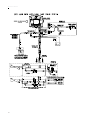
37
Accu-Flow Manual
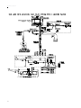
38
Manual # 016-0159-403
39
Accu-Flow Manual
40
Manual # 016-0159-403
41
Accu-Flow Manual
42
Manual # 016-0159-403
43
Accu-Flow Manual
44
RAVEN INDUSTRIES
LIMITED WARRANTY
WHAT IS COVERED?
This warranty covers all defects in workmanship or materials in your Raven Flow Control
Product under normal use, maintenance, and service.
HOW LONG IS THE COVERAGE PERIOD?
This warranty coverage runs for 12 months from the purchase date of your Raven Flow
Control Product. This warranty coverage applies only to the original owner and is not
transferable.
HOW CAN YOU GET SERVICE?
Bring the defective part, and proof of date of purchase, to your local dealer. If your
dealer agrees with the warranty claim, he will send the part, and proof of purchase to his
distributor or to Raven for final approval.
WHAT WILL RAVEN INDUSTRIES DO?
When our inspection proves the warranty claim, we will, at our option, repair or replace
the defective part and pay for return freight.
WHAT DOES THIS WARRANTY NOT COVER?
Raven Industries will not assume any expense or liability for repairs made outside our plant
without written consent. We are not responsible for damage to any associated equipment
or product and will not be liable for loss of profit or other special damages. The obligation
of this warranty is in lieu of all other warranties, expressed or implied, and no person is
authorized to assume for us any liability. Damages caused by normal wear and tear, misuse,
abuse, neglect, accident, or improper installation and maintenance are not covered by this
warranty.
Accu-Flow Installation and Service Manual (P/N 016-0159-403 Rev T 06/08)
Raven Industries
Flow Controls Division
P.O. Box 5107
Sioux Falls, SD 57117-5107
Toll Free (U.S. and Canada): 800-243-5435
or Outside the U.S.: +1 605-575-0722
Fax 605-331-0426
www.ravenprecision.com
[email protected]
Notice: This document and the information provided are the property of Raven Industries, Inc. and
may only be used as authorized by Raven Industries, Inc. All rights reserved under the copyright laws.