1
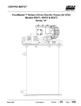
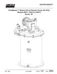
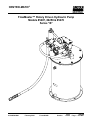
CENTRO-MATIC® PUMP, MODELS 85487 & 86258
TABLE OF CONTENTS
Page
Safety...............................................................................................2
Specifications.................................................................................2
Description......................................................................................2
System Operation..........................................................................2
Installing the Pump......................................................................3
Putting Pump into Operation.......................................................3
Maintenance & Repair...................................................................3
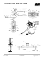
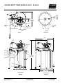
Dimensions....................................................................................6
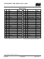
Repair Parts List............................................................................7
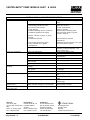
Troubleshooting...........................................................................8
SAFETY
Read and carefully observe these operating instructions
before unpacking and operating the pump! The pump must
be operated, maintained and repaired exclusively by
persons familiar with the operating instructions. Local
safety regulations regarding installation, operation and
maintenance must be followed.
Operate this pump only after safety instructions and this
service manual are fully understood.
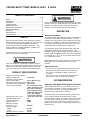
This symbol indicates a potentially hazardous situation
which, if not avoided, could result in death or serious injury.
Please refer to the 85481 operation manual, section C8,
page 269, series “B”© for all other safety considerations.
PRODUCT SPECIFICATIONS
Supply inlet hydraulic pressure,
maximum, PSIG (bar) Operating working hydraulic
pressure, PSIG (bar) Max. output pressure, PSIG (bar) Hydraulic inlet flow, GPM (l/min) Pump ratio with manifold -
Ambient oper. temp. ºF (ºC) Operating voltage, VDC Hydraulic inlet port, In Tank return port, In Maximum hydraulic
fluid temp., ºF (ºC) Weight, Lbs (Kg) - 86258
- 85487
Container capacity , Lbs (Kg) -
Page Number - 2
3,000 (207)
300 to 450 (21 to 31).
3500 (241)
Up to 7 (27)
9:1 at low inlet pressure
(300 to 350 PSI [21 to 24
bar]) and low inlet flow
(below 2 gpm [7.5 lpm])
Pump ratio approaches
11.0:1 ratio at higher
inlet pressure and flow.
-20 to +150 (-29 to +66)
24
SAE 4
SAE 6
200 (93)
Do not exceed 3,000 PSIG (207 bar) maximum supply inlet
hydraulic pressure or 3500 PSIG (241 bar) maximum outlet
pressure. Exceeding the rated pressures may result in
damage to system components and personal injury.
DESCRIPTION
General Description
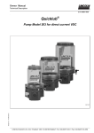
The Models 85487 and 86258 are pumping units designed
to operate a Centro-Matic® lubrication system. The units
include a vent valve to relieve the line pressure to recharge
the injectors. FlowMaster™ Rotary Driven Hydraulic Pump
includes pressure reducing valve, flow control valve and
solenoid operated (24 VDC) “On” and “Off” valve.
The FlowMaster pump is fully automatic when used with
Model 85530 Controller and a pressure switch. The
FlowMaster pump is double acting, dispensing lubricant on
both the “Up” and “Down” strokes. This unit is designed to
be used with SL-1, SL-11, SL-32 and SL33 series injectors
or a combination of these.
Model 86258 includes follower plate and low level indicator.
Model 85487 has no follower plate and no low level
indicator.
Appropriate Use
• The pump on this unit is exclusively designed to pump
and dispense lubricants using hydraulic power only.
• The maximum specification ratings should not be
exceeded.
• Any other use not in accordance with instructions will
result in loss of claims for warranty and liability.
SYSTEM OPERATION
Operation with Model 85530 System Controller
When Model 85530 times out, it will initiate a lube cycle.
The solenoid is energized to deliver hydraulic pressure to
the pump and vent valve. Pump begins dispensing
lubricant through injectors to the bearings.
When all bearings have received lubricant, pressure rises
in the system to actuate the pressure switch. When
pressure switch actuates, the control is reset to de-energize
the solenoid valve cutting off hydraulic oil pressure to the
pump and vent valve. Pump stops, pressure vents and
pressure switch de-actuates. Control begins timing toward
next lube event.
93 (41)
83 (37)
60 (27)
4.1A-68560-G00
Form 403048