1
CENTRO-MATIC® PUMP, MODELS 85487 & 86258
10. If foreign material is present, clean components and
reassemble. Be sure to always replace gaskets (20) &
(24) whenever vent valve is disassembled. Reverse the
above procedure to reassemble. Torque check
assembly to 100 ft.-lbs. (13.5 N-M).
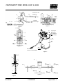
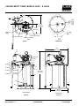
Vent Valve Service (See Figures 3, 7 & 8 Pages
5 & 6)
1. Turn off and disconnect the hydraulic and electrical power
supply to the pump assembly.
2. Standard tools required are a bench mounted vice, a set of
open end wrenches ranging from 7/16” to 1-1/2”, a large
24” (600 mm) adjustable wrench and a smaller 10”
(254 mm) adjustable wrench.
3. Remove delivery hose (17). Loosen Adapter Union (48)
and Vent Hose (14).
4. Remove bolts and lock washers (52 & 53). Remove vent
valve.
5. Hold base of vent valve in vice to remove elbows (12 & 15).
Turn vent valve in vice so that vice jaws are gripping flats
machined on base of vent valve.
6. Remove hydraulic cylinder (27). Remove piston and
packing (28) from cylinder. If oil leakage was evident
from side of hydraulic cylinder then replace packing.
7. Remove packing assembly (30). If grease leakage was
evident from side of hydraulic cylinder, then replace
packing assembly.
8. Inspect needle (29) and valve seat (31). If foreign matter is
lodged and is keeping the needle from sealing in valve
seat, clean and inspect for damage. If seat appears
damaged by nicks, grooves or scouring it should be
replaced. Remove valve seat (31) from valve body (33) by
placing a ¾” open end wrench onto the flats and loosening
the seat. The use of an adjustable wrench in place of the
open end wrench may be necessary due to the
accessibility of the seat.
9. Replace the valve seat (31) if damaged. Also be sure to
remove and replace the gasket (32) below the seat.
10. Reassembly is the reverse of the above procedure.
Needle (29) and hydraulic cylinder (27) inside diameter
should be coated with oil or grease to assist in
assembly.
11. Upon reassembly tighten valve seat (31) into body (33)
using 25 ft-lbs. (39 N-M). Tighten hydraulic cylinder (27)
onto valve body (33) using 100 ft-lbs. (135 N-M)
5. Now remove the entire follower assembly from the pump
tube. After removing the follower assembly from the pump
tube wipe off the excess grease which will allow clean
access to the eight bolts that must be removed.
6. Loosen and remove the eight nuts (62) on top of the
follower.
7. Remove the follower weight and the wiper (60).
Replace the wiper with a new one.
8. Reassemble in the reverse of the above procedure
making sure that the long bolts are staggered with the
small ones and that they extend below the follower.
Low Level Indicator (see Figure 4 & 5 Page 5)
If the indicator pin appears to drop prematurely or water is
noticeable on top of the follower then the indicator seal (1)
may be damaged.
1. Remove the eight bolts (39) and lockwashers (40) which
hold the cover on to the reservoir.
2. Inspect the reservoir gasket seal (41) for damage. If
damage is apparent then replace the gasket seal.
3. Remove the entire pump, vent valve and follower assembly
from the reservoir.
4. Remove the retaining ring (56) from the indicator rod
assembly (3).
5. Hold the indicator plug (4) with a wrench while removing
the indicator nut (2).
6. Remove and replace the O-ring (1).
7. Reassemble in the reverse of the above procedure.
Torque the indicator nut (2) to 20 ft.-lbs.
Safety Unloader Valve
(See Figure 1 Page 5)
Safety unloader valve (11) is not serviceable and should be
replaced if malfunction is apparent. Upon reassembly,
tighten to 10 ft-lbs. (13.5 N-M).
The Safety Unloader (11) is set to open at 3,750 to 4,250 PSI
lubricant pressure. If pressure Switch fails to operate and shut
off hydraulic supply to pump, the Safety Unloader will open at
approximately 4,000 PSI to relieve lubricant supply line pressure
(Safety Unloader is preset and cannot be adjusted.)
Bare Pump Assembly (See Figure 4 Page 5)
Please refer to the Operation Manual (C8, Page 269 series)
for the bare pump assembly (34).
Follower (see Figures 4, 5 & 6 Page 5)
If follower wiper appears to be damaged or does not wipe the
sides of the container effectively service may be necessary.
1. Disconnect hydraulic supply from pump.
2. Remove the eight bolts (39) and lock washers (40) which
attach the cover to the reservoir.
3. Lift the entire pump, vent valve, cover assembly and
follower out of the reservoir.
4. Unscrew the low level indicator (3) from the follower
plate (50).
Page Number - 4
4.1A-68560-G00
Form 403048