1
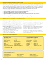
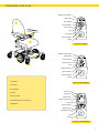
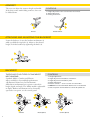
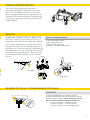
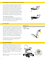
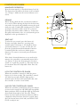
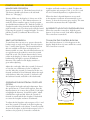
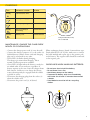
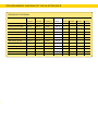
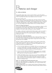
Article No.
Changed140901
Valid from 130517
INSTRUCTIONS FOR USE AND CARE
REAL 6100 PLUS
REAL 6100 PLUS is an electrically powered indoor wheelchair for people with various disabilities.
®
The REAL chair as specified below model is CE certified in accordance with the MPA statutes of medical
devices LVFs 2003:11.
For people with impaired vision we refer to a PDF-file, with enlargement abilities, of this manual at
http://mercado.se/int/documentation
INDEX
TECHNICAL INFO
PAGE 3
USER GUIDE
PAGE 5
CONTROL BOX SHARK
PAGE 7
CONTROL BOX DX-REMG90A
CONTROL BOX DX2-REM421
CONTROL BOX DX2-REM550
PAGE 8
CHARGING
PAGE 9
TROUBLESHOOTING CONTROL BOX SHARK
TROUBLESHOOTING CONTROL BOX DX2
TROUBLESHOOTING REAL 6100 PLUS
PROGRAMMING DIAGRAM OF THE ELECTRONICS PAGE 11
SERVICE/
SERVICE MANUAL
INDIVIDUAL CUSTOMIZATION
PAGE 12
GET ACQUAINTED WITH YOUR REAL 6100 PLUS – PLEASE READ THESE OPERATING
AND MAINTENANCE INSTRUCTIONS AND THE USER GUIDE BEFORE USING
THE WHEEL CHAIR.
PRE-USE INSPECTION CHECKLIST
•
•
•
•
•
•
•
All knobs and locking wheels shall be tightened
on the chair before use.
The leg support may not be adjusted so that it touches
the floor or the ground at any time.
If the REAL 6100 PLUS is equipped with a belt or
a harness of any kind it may not hang loosely on
the chair but used as intended or taken off.
Make sure the foldable armrests are in an upright
position before driving the chair.
Fold down the footplate.
Attach the backrest.
Don’t use the chair when backrest and/or armrests
are unmounted.
Mercado Medic UK Ltd
PO Box 4818
Warwick, CV34 9GB
PRE-USE INSPECTION CHECKLIST
CONTROLLER
•
•
•
Turn on the main switch.
Make sure the battery level indicator should not be
down at the red mark.
Make sure the controller does not display any errors
(please go to “Troubleshooting”).
Phone, Fax
Ph. +44-(0)844 561 6874
Fax. +44- (0)844 561 6875
Internet, E-mail
www.mercado-medic.co.uk
[email protected]
IMPORTANT INFORMATION AND CLASS
The REAL 6100 PLUS chair has exchangeable components, accessories and functions that can be adjusted to suit individual needs. The chair should only be used by the person and for the purpose for which it was originally intended. The
chair is designed for indoor use and should not be exposed to water, other fluids or chemicals nor should it be exposed
to high temperatures intensive sunlight or similar. The chair may not be equipped with other accessories or components
than those approved by Mercado Medic. Repairs and other technical adjustments may only be carried out by personnel
authorised by Mercado Medic. Please read through these instructions carefully before using your chair.
•
•
•
•
•
•
•
•
REAL 6100 PLUS is classified as A and is intended for indoor use only.
Max users weight: 135 kg. If you want to adjust for heavier users – contact Mercado Medic AB.
REAL 6100 PLUS is tested and approved according to the EMC-directive.
Mobile Phones do not affect the manoeuvring of REAL 6100 PLUS.
REAL 6100 PLUS may not be equipped with other accessories or components other than those authorised
by Mercado Medic AB.
Repairs or other engineering work must be performed by personnel authorised by Mercado Medic AB.
Chairs with adjustable seat angle should be in fixed position when sitting in or rising up from the chair.
REAL 6100 PLUS shall not be operated when the seat height is in the raised position.
STORAGE, CLEANING AND MAINTENANCE
Keep the chair in a dry, room temperature environment.
Check battery level prior to use. If the chair is to be stored
for longer than a month the battery terminals should be
disconnected. The chair is intended for indoor use and
should not be flushed with water, other liquids or chemicals.
The chair can be cleaned/wiped clean with disinfectants.
Do not expose the chair to high heat or prolonged/intense
sunlight or other radiation.
The chair should be wiped clean and kept free of dust
and dirt and the upholstery cleaned with foam upholstery
cleaner. Remove loose dirt from the fabric.
• Apply a thin layer of foam and rub it into the
fabric evenly with a damp cloth.
• Wipe dry with a clean, damp cloth.
• Vacuum well when dry.
The seat, backrest and other padded parts are, for functional
purposes, not made of impermeable materials. For hygienic
reasons, when the upholstery is changed, the seat and
padding material should be replaced.
The electronic lifting device should be checked regularly for
dust and dirt. Put the seat into its highest position. Clean
with a cloth. (Water or solvents may not be used).
Then lubricate the cylinder with a thin layer of Teflon- or
siliconbased grease, which does not become overviscous like
greases based on mineral oils.
TECHNICAL INFORMATION
TECHNICAL DATA
Max user weight
Top speed
Turning space180°
Driving wheel
Driving time per charge
Obstacle ability
Weight
Charging time
Charger tested and approved
by Mercado Medic AB
Batteries tested and approved by Mercado Medic AB
STANDARD MEASUREMENTS
135 kg
4,5 km/h
870 mm
both center wheels
approx. 15 km
40 mm
76 kg incl. batteries
approx. 6-8 hours
ECB-401 Easy Buddy 4A
Sonnenschein 2pcs 12V 25 Ah
Total width
Length
Wheel front/back
Driving wheel
Seat height
Leg support length
Seat width
Seat depth
Seattilt
Back support height
Back support angle
570 mm
795 mm
Ø 125 mm
Ø 225 mm
480-760, 410-610 mm*
370-530 mm
290-480 mm
320-530 mm
-15°+8°, -8°+15°, 0° +23°
330-430 mm
-15-+45°
*with the ability to adjust down to a maximum
of 3 cm.
PROGRAMMING DEVICE
Selection of programmable functions:
• Forward speed
• Forward acceleration
• Forward deceleration
• Reverse speed
2
• Reverse acceleration
• Reverse deceleration
• Turning speed
• Turning acceleration
• Turning deceleration
• Joystick sensitivity
• Reversed joystick function
• Use of external joystick
YOUR REAL 6100 PLUS
Battery level indicator
Main switch
Seat
2 function
1
1
2
Speed indicator
Lower speed
Horn
3
2
Accelerate
Service indicator
Joystick
4
Control box SHARK
Battery level indicator
Main switch
7
5
Drive function
Speed indicator
6
1
2
3
4
Horn
Electric functions
Option buttons
Service indicator
Joystick
1. Backrest
Control box DX 2-REM421
2. Armrest
3. Controller
Main switch
4. Seat
5. Drive wheel
6. Individual wheel suspension
Left indicator
2
Right indicator
1
2
Battery level indicator
Display
7. Footplate
2
Function buttons
Option buttons
Operating program
Horn
Joystick
Control box DX 2-REM 550
3
ARMREST
CONTROLS
The user can adjust the armrests height and width.
If the chair comes with folding armrests, these can
be folded down.
1. Height adjustment. Turn to lower/raise the armrest.
2. Width adjustment.
3. Folding mechanism.
1
2
3
1
2
Armrest
Foldable armrest
ATTACHING AND ADJUSTING THE BACKREST
Lower the backrest (1) into the backrest mechanism (2)
while you hold the snap lock (3). Adjust to the desired
height. Lock the backrest by tightening the knob (4).
1
3
4
2
BACKREST
THERE ARE FOUR TYPES OF BACKREST
MECHANISMS:
Standard, Medic, Comfort and Electric.
All are available as low-and high-performance
(all illustrated chairs have low mechanism).
All backrest mechanisms have separate controls for
height, depth and angle. The Medic model is adjustable
in depth. Backrest mechanism can be electrically
operated as an option, see the control panel.
CONTROLS
1. Height adjustment.
2. Angle adjustment of backrest mechanism.
3. Angle adjustment of backrest plate.
4. Depth adjustment.
5. Electric controls – see the section for control box.
6. NOTE! Ensure that the Medic backrest fits in the bracket
so that snap locks and the backrest cannot be pulled out.
3
3
3
1
1
1
2
4
6
2
2
Standard
4
1
Medic (Option)
Comfort (Option)
TRANSPORTATION SERVICE
Users must not be seated in the chair when
transporting the REAL 6100 PLUS. Users must
move over to the dedicated vehicle seat. The chair
must be equipped with transport loops and must be
anchored to the vehicle using straps. Transport loops
are accessories that can be ordered separately, article
number 802210.
SEAT TILT
THERE ARE THREE TYPES OF SEAT TILTS:
Gas spring, crank control and electric tilt. The gas
spring lever is located at the rear right side under the
seat (1) and is adjusted by moving the lever slowly
forward. The controls are alternatively under one of
the armrests (2). Crank operated tilt is adjusted using
the crank from the rear (3). The range of the tilt can
be reduced using attached nuts (4). Electric seat tilt
is controlled from the controller, see the controller
section.
SEAT TILT MECHANISMS
1. Gas spring under armrest.
2. Gas spring under seat.
3. Crank control under seat.
4. Electric – see control box section.
1
Gas spring
3
Crank control
2
REVERSE TILT OR ALL TILT BACKWARDS (OPTIONAL)
CONTROLS
1
2
3
3
2
1
1. Armrest attached here move with the seat tilt.
2. Armrest attached here do not move with the seat tilt.
3. There are three positions. When selecting position 3,
the seat must be equipped with base extensions.
1. Front 15˚, back 8˚ – standard seat tilt.
2. Front 8˚, back 15˚ – reversed seat tilt.
3. Front 0˚, back 23˚ – all seat tilt backwards.
5
ADJUSTING THE CONTROLLER POSITION
The controller can be adjusted for depth and sideways
position. To adjust the depth, undo screw (1) with
a 5 mm Allen key. Move the controller arm to the
required position (out of three possible) and reattach
the screw. The controller can also be moved sideways
to either the inside or the outside of the armrest.
The control arm is jointed at two points. This allows
the control box to be moved horizontally and sideways
without the use of tools. Push the controller into the
desired position and it locks into position by itself.
The controller can be placed on either side of the chair.
1
WITH PARALLELOGRAM
The magnetic attachment allows the controller to be
positioned parallel to the arm rest. Adjust the position
of the screw (1) then lock the screw. Adjust the control
box to the desired position, then release.
1
FOOTPLATE
The footplate has a height and an angle adjustment.
To adjust the height of the footplate: loosen screw (1).
Adjust the footplate to the required height and tighten
the screw. Note! Ensure that the screw enters one of
the inner tube’s countersunk depressions.The angle of
the footplate is adjusted using screw (3) with a 5 mm
Allen key. To lower, turn the screw clockwise; to raise,
turn the screw anti-clockwise. The leg position can be
adjusted to four positions. Loosen and remove screw
(2) with a 5 mm Allen key. Set the required angle,
return the screw into the relevant hole and tighten.
Calf/heel support and base plate with depth 100 mm
are available as options. Also with depth, width,
height and angle adjustment.
CONTROLS
1. Height.
2. Angle – legrest.
3. Angel – footplate.
2
1
3
BRAKE RELEASE
Releasing the brake enables the chair to be moved
manually. To disengage the brakes press the switch
away from you (1), upwards in the picture on the
right. To apply the brakes again, push the controls
back to the original position. If the chair is disengaged
when it is on, the panel will display an alarm which
means that the chair is not possible to use. As soon as
the brake is engaged, the alarm is off and the chair is
again possible to use.
Note! The chair must never be transported with the
brakes disengaged.
6
1
CONTROLLER SHARK
MANEUVER OPERATION
Press the main switch (1). Check the battery level (4).
The battery level should not be down at the red mark
(see “Charge”). Make sure the service indicator (9) is
not lit.
4
1
2
DRIVING
Before driving check that the seat function indicator
(6) is not lit. When driving the chair for the first time,
start with a low speed and gradually increase the speed
until you reach a comfortable cruising speed. To reduce
speed press the button with a turtle (2), to increase
speed press the button with a rabbit (3). To fine-tune
the speed, hold switch (2 alt. 3) to the desired speed is
displayed on the speed indicator (7).
6
1
2
2
3
7
8
9
5
SEAT UNIT
To select the seat control, press the button (6).
Pressing once lights function 1, pressing twice
switches mode to function 2. Seat height is always
operated by function 1. To raise or lower the seat
press the joystick forward alt backwards. Function
is switched off if the seat has no further power
functions. To return to run mode press the button
(6) again.
Control box SHARK
If the chair’s electrical functions are not used in five
minutes, the controller is automatically turned off to
save battery. To boot the electronics press the main
switch (1) or push the joystick (5). The time interval
for automatic shut-off is adjustable. Horn: Press the
button (8).
LOCK THE CONTROLLER, SHARK
When the controller is turned on, hold the power
button (1) for four seconds. The controller is turned
off. After four seconds, all LEDs light up for a
moment and a the horn will sound. After that, turn
the controller on and it is now locked.
UNLOCK THE CONTROLLER, SHARK
When the controller is locked. Press the power button
to turn on the control box. All LED lights up quickly.
Battery indicator LED (8) will then light up and count
down slowly from right to left. Press the “Horn”
button (8) twice before the battery indicators LED is
completely related. You have about 10 seconds. After
that, the current battery level and your REAL 6100
PLUS is ready for use.
7
CONTROLLER DX2-REM550
MANOEUVRE OPERATION
Press the main switch (1). Check the battery level (4).
The battery should not be down at the red mark.
(Please see “Charging”).
Driving: Make sure the display (3) shows one of the
driving programs 1 to 5. Press function buttons (2)
until any of these numbers appear. Set the program
speed with function buttons (6). Push the joystick (5)
straight forward to drive forwards and diagonally left/
right-forward to turn. The chair can be turned around
by moving the joystick (5) straight left/right. To reverse,
pull the joystick (5) backwards. Horn: Press the
button (8).
SEAT UNIT OPERATION
To raise/lower the seat unit or to operate electric tilt,
backrest angle or angle of footplate. Press the Option
key (7) until a chair appears. The electrical functions
that are available on the chair are displayed (one
function visible at a time). Press the function button (6)
to toggle between the symbols or move the joystick
from side to side. The electric function that is active
is blue in the display (3). Move the joystick forward/
backward alt. left/right to operate the different
functions. The symbol on the display switches to
green when adjusting.
Adjust the seat height: Move the joystick (5) forward
to raise the seat, and down to lower it. Adjust
the
1
2
seat tilt: Move the joystick (5) forward to tilt the seat
forward, and back to tilt it backward. Adjust the angle
of the backrest: Move the joystick (5) forward to tilt
the backrest forward, and back to tilt it backwards.
2
OPERATING THE ELECTRICAL FOOTPLATE
OPTION
The footplate has height and angle adjustment. Press
the option button (7) until a chair appears. Press the
function button (6) or move the joystick (5) left/ right
to highlight the function “electrical footplate” which
is divided into right and left. Move the joystick (5)
forward to extend and tilt the footplate or backward
to retract the footplate and move it backward.
To adjust the left footplate only, navigate to No. 1 and
move the joystick (5) forward to tilt the footplate up
or move it backward to tilt it down. To merely extend/
shorten the footplate on the left side navigate to No. 2
and move the joystick (5) forward to extend the
8
footplate and back to make it go back. To adjust the
right footplate only navigate to No. 3 (see No. 1) and
No. 4 for vertical adjustment (as explained in # 2).
When the chair’s electrical functions are not used
in five minutes it will turn off automatically to save
battery. To boot the electronics press any key. The time
interval for automatic shut-off is adjustable.
IN ORDER TO LOCK THE CONTROLLER, DX2
When the controller is turned on, hold the power
button (1) for four seconds. Lock will be displayed.
The control box is turned off.
TO UNLOCK THE CONTROL BOX DX2
Press the Power button (1). A lock appears in the
display. Push the horn (8) twice within 10 seconds.
The control box is started.
1
4
3
2
6
7
2
8
5
Controlbox DX2-REM550
CHARGING
LED
SIGNIFIC. / CAUSEACTION
Steady
Connected to mains
Flashes
Battery is charging
Steady
Battery fully charged
Steady
Reverse polarity to Contact Service
the battery
Flashes
Battery errorContact Service
Charger 6100 PLUS, 4 amp.
Art. no. BAC1010
MAINTENANCE, CHARGE THE CHAIR EVERY
MONTH OR CONTINUOUSLY
... Connect the charger power cord (3) into the wall.
... Connect the charger connector (1) to the socket (2)
(labeled battery symbol). Power cord and charging
plug can be connected in any order.
... Green LED (4) flashes during charging.
The charger get warm when charging. This is
normal. Overheat protection available.
... Green LED (4) lights when the battery is ready for
use which takes at least six hours, regardless of
battery capacity at the start. Since the charger draws
little current, and do not over charge the battery,
it may advantageously be engaged until the vehicle
is placed in service.
... Disconnect the charging plug from the socket (2)
when the vehicle used.
... Disconnect the power cord (3), if desired.
When exchanging battery (brand: Sonnenschein, type:
Dryfit A500 A512 12V 25 Ah), make sure to connect
the cable marked with a plus sign to the positive pole
on the battery. The negative cable should be connected
to the negative pole.
GUIDELINES WHEN HANDLING BATTERIES:
• Do not ever short-circuit the battery.
• Do not throw it on a fire.
• Avoid heavy bumps to the battery.
• If exposed to battery acid, rinse immediately with water for at least 15 minutes then contact
a doctor.
• Used batteries must be left at a recycling station.
4
1
3
2
9
DETAILED INFORMATION – CHARGER 6100 SERIES 3/4
SAFETY INSTRUCTIONS
The chargers are especially designed to charge maintenance free lead acid batteries. The charger housing
should only be opened and maintained by authorized
personnel. Unqualified opening may cause damage
to the charger and will void the guarantee. Operation
with an opened housing is strictly prohibited. Only a
qualified technician is allowed to replace the fuse. The
charger should only be operated if sufficient cooling
is assured. The chargers should only be operated in
closed rooms and must be protected against moisture.
PUTTING INTO OPERATION
Compare the rated voltage of the type plate of the
charger with the rated voltage of the battery. If
identical, connect the battery with the correct polarity.
Red cable to plus (+) terminal, black cable to minus (-)
terminal of the battery. Connect the mains supply.
When the polarity is correct a LED 1 and LED 3
ignites. The LED 3 will turn of shortly and the LED
2 ignites. The battery will now be charged with the
rated current. If connected with reverse polarity, the
LED 4 illuminates. In this case disconnect the mains
supply immediately, charge the battery connection
and repeat the start procedure after 30-60 seconds.
If LED 4 and LED 3 illuminates after connecting
battery and mains, the battery is not connected or
the battery wiring is damaged.
SPECIAL INSTRUCTIONS TO AVOID SPARKS:
•
•
•
•
Connect mains supply without battery connection.
Disconnect mains after a short period of time.
Connect battery with correct polarity.
Connect mains supply.
• Never store a discharged battery.
• A completely discharged battery must be charged
for min. 16 hours.
• If the charging time is below 16 hours for more than
three times, then charge one time for 24 hours to
equalize the poor charging.
• The ambient charging temperature should range
between10ºC and 30º.
BEFORE LONGER STORAGE PERIODS
(TWO POSSIBILITIES):
A. Disconnect the battery from the charger and store it
fully charged. Before storage periods exceeding
three months charge the battery for min. 36 hours.
B. You can leave the battery on charge for an unlimited
time (maintenance charge). It is recommended to store the battery in a cool place.
HIGH AMBIENT TEMPERATURES
Charging in temperatures above 30°C is not
recommended. Your charger is adjusted with a
charging voltage valid for 20°C.
LOW AMBIENT TEMPERATURES
Charging below 10°C is not recommended. In low
temperatures the available capacity is reduced.
DEEP DISCHARGE
Try to avoid deep discharges. If a deep discharge
occurred, charge the battery as soon as possible for
24 hours.
GENERAL
The charger is designed in the primary switch mode
technology. The technology provides a constant
RECOMMENDATIONS FOR CHARGING
DC voltage which guarantees for a long lifetime for
SEALED LEAD ACID BATTERIES:
maintenance free sealed lead acid batteries. A holding
Charge/Discharge
device for wall mounting will be found on the back of
• Charge 12 hours prior to initial use.
• Charge after each discharge even after partly the charger.
discharge.
WIRING DIAGRAM FOR CONNECTION OF OTHER CHARGERS
Interlock
Battery +
Battery -Charging plug 3 pin XLR
(from the front)
10
Battery charger
shall meet
SS-EN 12184
ISO 7176-21
PROGRAMMING DIAGRAM OF THE ELECTRONICS
STANDARD PROGRAM
DX2
SHARK
PROG. 1
PROG. 2
PROG. 3
Max forward speed
25 %
45 %
75 %
75 %
Forward acceleration
20 %
25 %
30 %
30 %
Braking, forward
35 %
40 %
50 %
75 %
Max reverse speed
20 %
25 %
50 %
50 %
Reverse Acceleration
20 %
20 %
25 %
25 %
Reverse brake
35 %
35 %
50 %
50 %
Max turning speed
15 %
20 %
45 %
40 %
Turn acceleration
20 %
20 %
25 %
30 %
Turn braking
35 %
40 %
55 %
55 %
Joystick sensitivity
50 %
50 %
50 %
40 %
Grip / Traction
100 %
100 %
80 %
80 %
USER SETTINGS
PROG. 1 PROG. 1 PROG. 2 PROG. 3 PROG. 4
GUIDELINES FOR INDIVIDUAL CUSTOMIZATION OF MERCADO MEDICs PRODUCTS
Customizations shall only be done by authorized personnel who have received Mercado Medic training
program for service and reconditioning.
Articles that are on the list over current combination agreements are allowed to be fitted with maintained
CE-marking. If an article wants to be fitted that is not on this list must authorized personnel contact
Mercado Medic and ask for a written approval.
Article to be approved must physically be sent to Mercado Medic for evaluation. Mercado Medic will
then contact the supplier of the article in order to sign a mutual combination agreement. In that process
Mercado Medic conducts a risk analysis for the article in combination with Mercado Medics product.
When the risk analysis is conducted the customer/supplier receives a written notion.
Chairs that have undergone changes, as described below, shall be verified by Mercado Medic to maintain
product liability.
• Upholstered parts such as seats, backrests, armrests, side supports and neckrests can be customizedas it
do not exceed the original product measurements or centre of gravity.
• Center of gravity in relation to the actuator must be maintained.
• Upholstered parts shall meet current fire and environmental requirements.
• Surfaces put under considerable load must not be outside the square formed by the wheels on the base.
If these guidelines are fulfilled Mercado Medic will keep the product responsibility (CE).
Special customization done by the healthcare beyond Mercado Medic guidelines overtake the responsibility
for the product in its form, but also how it is put back in its original form. This must be done by
an authorized technician approved by Mercado Medic. Mercado Medic then overtake the product
responsibility according CE93/42EEC; Medical Products Directive MDD.
For questions regarding adjustments/customizations, contact Andreas Teske.
Phone +46 8-555 143 19
Email [email protected]
Mercado Medic UK Ltd
PO Box 4818
Warwick, CV34 9GB
www.mercado-medic.co.uk
Phone, Fax, E-mail
Ph. +44-(0)844 561 6874
Fax. +44-(0)844 561 6875
E: [email protected]