1
Donated by John & Susan Hansen - For Personal Use Only
L-UNE MOTOR TRUCK SERVICE MANUAL
STEERING GEAR
Index
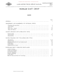
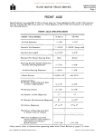
Page 1 STEERING GROUP The following list shows the L-line truck models and their corresponding steering gear
models. Specifications of the individual steering gear models will be found on specifications
page 1.
TRUCK MODELS
STEERING GEAR
MODELS
L-110 .. " . . . . . . . . . . . . . . . . •
L-IZO . . . . . . . . . . . . . . • . . . . . • .
LM-IZO . . . . . . . • . . • . . . . . . . • .
L-13 O. • . . . • . . . . . . . . . . . . . . . .
LB-140 . . . . . . • . . . . • . . . . . • . .
L-150. . . . . • • . . . • . . . . . . . . • .
L-153 . . . . . . . . . . . . . . . . . . .
LM-150
.............. .
L-160 . . . . . . . • . . • . . . . . . . . . • .
L-163 . . . . . . . . . . . . . • . . . . . . . .
L-l 64. . . . . • . . . . . . . . • . . . • • . .
L -1 65. . . • . . . • . . . • . . . . . • . . . .
LC-160 . . . • . . . . • • . . . . . . .
L-1 70. . . . . • . . • • . . . . . • . . . . . .
:"'-173 . • . . . . . . • . . . . . . . . . . . . •
:"'-174• . . . . . . . . . . . . . . . • . . . . .
:"'-175 . . • . . . • • . . . . . . . . . . . . . .
-,F-170 . . . . . . . . . . . . . . . . . • . . .
.... -lBO • • • . • • • • • . • • • • • • •
..1-1 83. . . • • . • • • . • . • • • . • . . • . •
TA-1Z
TA-IZ
TA-14
T-14
T-14
TA-14
TA-14
TA-14
TA-54
TA-54
TA-54
TA-54
TA-54
TA-54
TA-54
TA-61
TA-54
TA-61
TA-61
TA-61
TRUCK MODELS
STEERING GEAR
MODELS
L-IB4 • . . . . . . . . . . . . . . . . . . . .
L-IB5 . . . . . • . . . . . . . . . . . .
LC-IBO . . . . . . . . . . . . . . . . . . . . .
L -190. . . . . . • . . . • . . . . . . . .
L-193 . . . . . . . . . . . . . . . . . . .
L-l94. . . . . . . . .. . . . . . .
L-195 . . . . . . . . . . . . . . .
LC-l90 . . . . . . . . . . . . . . . . LF-190 . . . . . . . . . . . . . . . .
L-ZOO . • . . . . . . . • . . . . . . . . . . .
L-Z04. . . . . . . . . . . . . . . . . . . .
L-Z 05 . . . . . . • . . . . . • . . .
LC-ZOO . • . • . . . • • . . . . . . L-ZlO . . . . . . . . . . . . . . . •
LF-ZlO . . . . . . . . . . . • . . . . • . . .
L-ZZO . . . . . . . . . . • • . . . . • . . . . LF-ZZO . . . . . . . . . . . . . . . . . L-ZZ5 . . . . . . . . . . • . . . . . . .
L-Z30. . . . . . . . . • • . . . LF-Z30 . . . . . . . . . . . . . . . . • TA-61 TA-61 TA-61 T-66 T-66 T-66 T-66 TA-66
TA-66
TA-66
TA-66
TA-70 TA-70 TA-70 INDEX
Page ;pecifications . . . . . . . . . . . . . . .
1
SECTION "A"
l.djustments • . • . . . . . . . . . . . . . • . . . . . . . . . . . . . . . . . . . . . . . . . . • . . .
;onstruction . . . . . . . . . . . . . . . . . . . . . . . . . . . . . . . . . . . . . . . . . . . . .
Jisassembling steering gear . . . • . . . . . • . . . . . . • . . . . . . . . . . . . . . . . .
lrag links. . . . . . . . . . . . . . . . . . . . . . . . . . . . • • . . • . . . . . . . . . • . . • .
'lstalling steering wheel • . . . . . . . . . . • . . . • . . . . . . . . • . . . . . . . . . . . .
acket tube bea ring. . . . . . . . .
. . . . . . . . • . . • • • . . . . . . . . . • . . . .
.eassembling steering gear . . . . . . . . . . • . . . . . • • • . . . . . . . • . . . . . . . .
.emoving stee ring wheel . . • . . . . • . . . • . . . • . • . . . . . . . . . . . . . • • . .
tee ring column alignment. . . • . . . • . . . . .
. •................
tee ring gear connection with front wheels . . . . . . . • . . . . . . . . . . • . . • .
PRINTED IN UNITED STATES 01'" AMER1CA
1, Z 1
4
5
4
6
4, 5 3
3
3
Donated by John & Susan Hansen - For Personal Use Only
Donated by John & Susan Hansen - For Personal Use Only
~
r
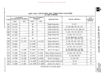
STEERING GEAR SPECIFICATIONS
i
STEERING GEAR MODELS
Steering Gears:
Make . . . . . . . . . . . . . .
I
TA-12
Ross
Ratio . . . . . . . . . . . . . . 15.4:13.5:15.4
Lever Shaft Diameter . . .
.9360
z
I
T-14
TA-14
Ross
Ross
17:15:17
20: 18:20
.9980
1.1230
TA-54
Ross
TA-61
Ross
T-66
Ross
20:18:20 22: 18:22 19:17:19
1.1230
1.248
1.3730
TA-66
Ross
[TJ
TA-70
3::
o
-1
o
Ross
:::a
-1
23.4: 19.5: 23.4 23.4: 19.5:23.4
1.3730
:::a
C
(')
r;
1.4975
Pitman Travel: (f)
[TJ
Available •
0
• • • • • • • • •
120
0
116 0
116 0
116 0
112 0
104 0
112 0
:::a
106 0
<
(')
Steering Post Diameter . . . . .
Steering Jacket Diameter . . . .
7/8"
1-1/2"
7 /8"
1-1/2"
7 /8"
1-1/2"
7/8"
1-1/2"
[TJ
1"
1"
1"
1"
3::
»
1-3/4"
1-3/4"
1-3/4"
z
1-3/4" c
»r
(fl
o-l
M
(flM
~~
8·2
~Cl
'1:!~Cl
P>~M
0 "
ro ::l ,.....
(IQ
-Ul~
Donated by John & Susan Hansen - For Personal Use Only
Donated by John & Susan Hansen - For Personal Use Only
L-UNE MOTOR TRUCK SERVICE MANUAL
STEERING GEARS
Section A
Page I
STEERING GEARS TA-12 I T-14 I TA·14 I TA-54 I TA-61 I T·66 I TA-66 I TA-70
~
~~,
'\ ~ Jacket tube
Nut and
lock washer
4 Upper cover
~/5 Shim.
7
3
Cap Screws ...... ...••..t /
3 :t.
Screws
5"
Shims \
Id '
Cam--~~
Adjusting'lO' screw 9
Lock nut Lock nut
2
Arm
9
-"::;:::;:f":
... "
End cover and
tuhe assembly
A.22452
Fig. I - Models lA-12, l-Iq, TA-JlL
01J
End cover and
;"
tube assembly
A.22479
Fig. 2-Models lA-Sq,lA-61,l-66, lA-66 , lA-70.
Lever shaft
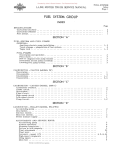
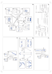
Construction (See Figs. 1, 2, 3)
L-Line Trucks are equipped with (Ross)
semi-reversible cam and twin-lever steering
gears. The twin-lever construction is shown
in Figs. I and 2.
There are two types of twin-lever gears used:
1. Twin-lever with sliding studs -- the studs
are riveted in the lever so that the studs
have a sliding contact with the cam (Fig.
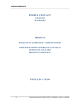
BOTTOM OF GROOVE
NOTE VARIATION
SHAllOWER AT A & B
PERMISSIBLE
LASH IN
POSITIONS
I).
2. Twin-lever with rolling studs -- the studs
are mounted in the lever with tapered rol
ler bearings so that the studs have a roll
ing contact on the cam (Fig. 2).
GEAR IStuds A & BI SHOWN AT MID-POSITION OF TRAVEl
Both studs of the twin-lever gear engage
the cam for normal straight-ahead driving. As
the steering action muves away from the normal
driving position into the parking range, one of
the studs dis engages the cam. The effective
leverage of this single stud increases so rap
idly, however, that in full parking the leverage
is 45 percent greater than with a single-lever
type steering gear. This is due largely to the
fact that because of the twin levers the steer
ing arm is shorter and, therefore, has a full
100 degrees of travel compared to 76 degrees
in a single-lever unit. Actually, the driver has
at his disposal a dual-ratio gear which auto
matically changes froITl one ratio to another to
suit the requirements of steering stability at
high speeds, and easy wheel turn for sharp
PRINTED IN UNLTED STATES OF AMERICA
c ,hows VARIOUS POSITIONS OF STUD A ON TURNS
b shows VARIOUS POSITIONS OF STUD B ON TURNS
IMPORTANT -ADJUST THRU THE MID-POSITION
A·23440
Fig. 3
turns in parking. A valuable safety factor is a
lessening of the tendency to over-steer on
c;urves and when passing other vehicles at high
speed (See Fig. 3).
Adjustments
NOTE: The basic design of the steering
gears used in these trucks is siITlilar and the
method of servicing applies generally to all
units used. For illustrative purposes, assem
blies of the more COITlmon type are used.
Donated by John & Susan Hansen - For Personal Use Only
STEERING GEARS
Section A
Page 2
L-UNE MOTOR TRUCK SERVICE MANUAL
Except for position of the lever shaft in the
housing, the steering gear details are similar
and are serviced in the same manner.
Filler plug (11---."11
When making adjustments, free the steer
ing gear of "all load, preferably by disconnect
ing the drag link from the steering arm, and
loosen instrument panel bracket clamp on
steering gear jacket tube.
If the ball thrust bearings on the cam must
be adjusted, make adjustment(l) before making
side adjustment to lever shaft studs in cam
groove (2).
1. ADJUSTMENT OF BALL THRUST BEAR
(9) \,Lock nut',\
INGS ON CAM.
(a) Before making this adjustment loosen
the housing side cover adjusting screw
(9, 10) to free the studs in the cam
groove (Fig. 4).
'--".'f
.... Fig. ~
Illustrates
screw and locknut
location
of
adjusting
(b) Adjustment should be made so there
is a very slight drag but not so much
that steering wheel cannot be turned
from extreme to extreme by lightly
gripping rim with thumb and fore
finger.
(c) Unscrew the four screws (3) and raise
the housing upper cover (4) to permit
removal of shims (5). (Shims are of
.002", .003" and .010"
thickness).
(Fig. 5).
(d) Clip and remove a thin shim or more
as required, and draw cover down
tight against shims.
(e) Test as outlined in paragraph (b) and
if necessary remove or replace shims
until adjustment is correct.
2. ADJUST LEVER SHAFT STUDS IN CAM
GROOVE FOR BACKLASH.
(a) Backlash at this point shows up as end
play of lever shaft, also as backlash
at steering wheel and at ball on steer
ing arm.
(b) The groove is purposely cut deeper in
ends of cam than in mid-position. This
produces a high range through mid
position and makes grooves narrower
through this range. This permits
take-up of backlash in mid-position,
after normal wear of groove, without
causing a bind in ends (Fig. 3).
(c) Adjustto this mid-position high range.
Do not adjust in end positions. Play
in end position is not objectionable.
(d) Tighten side cover adjusting screw
(10) until a very light drag is felt
through the mid-position high range
when turning steering wheel slowly
,
A-22530
Fig. 5 - Showing location of shims under upper
housing cover used to adjust end-play on cam.
(Shims are of .002", .003", and .010· thickness)
from extreme to
(Fig. 4).
extreme
position
(e) IMPORTANT: Steering gear must not
bind any position. Only a very slight
drag should be felt. A closer adjust
ment will not correct steering loose
ness caused by wear in other steering
gear members, but will damage parts
and impair operation.
(f) When
proper adjustment has been
made, tighten lock nut (9) and then
give gear a final test.
(g) Make sure steering gear arrn is tight
on splined lever shaft and that lock
washer and nut are tight also.
Donated by John & Susan Hansen - For Personal Use Only
STEERING GEARS
Section A
Page 3
L·L1NE MOTOR TRUCK SERVICE MANUAL
3. STEERING COLUMN ALIGNMENT.
(a) After adjustments have been made and
lock screw tightened, turn steering
wheel to see if any stiffness exists. If
so, steering gear has been adjusted
too tight or steering column is out of
alignment. Misalignment of the column
places a bend in the column, conse
quently, the wheel tube must undergo
reverse bending stresses during each
revolution. This is a serious condition
and mustbe avoided. THE STEERING
COLUMN MUST NOT BE SPRUNG
IN ANY DIRECTION.
4. STEERING GEAR
FRONT WHEELS,
CONNECTION
WITH
(a) The steering gear should be connected
to the front wheels so as to obtain as
nearly as possible the specified turn
ing radius on both left and right turns.
This is accomplished by turning the
steering wheel as far to the right as
possible, then rotate the wheel in the
opposite direction as far as possible
and note the total number of turns,
Turn the wheel back just onE?-half of
this total movement, thus placing the
gear in the mid'-position. With the
front wheels in position for straight
ahead driving, it should then be pos
sible to connect the drag link to the
ball on the end of the steering gear
arm without moving the gear to any
appreciable extent, If this cannot be
done, remove the arm from the steer
ing gear, using a suitable puller, and
place it on the splined shaft in the
proper position. Otherwise it will not
permit the front wheels to swing equal
ly to the left and right, Check steering
knuckle s top on front axle to make
sure that there is proper clearance
for the tire when turning at maximum
angle. Axle stops should also be set
out sufficiently to prevent steering
gear from lIbottoming", that is, to stop
the gear short of its absolute limit of
travel. If the gear is permitted to
bottom, damage to internal parts will
occur. Check to see if axle stops are
set to do this on both left and right
turns. See that steering gear housing
is filled with lubricant as recom
mended in "Lubrication Section".
5. A·21734
Fig,
5
4
3
2
IO
A·21736
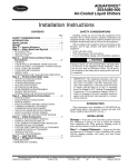
Fig. 7, Models TA-61, T-66, TA-66, TA-70
TO REMOVE STEERING WHEEL (Figs.
6 and 7),
(a) Disconnect horn wire at bottom of
steering gear.
(b) Remove horn button (8) by pressing
down and turning to right or left with
PRINTED,N UNrTED STATES
or
AMERICA
6, Models TA-12, T-14, TA-14, TA-54
LEGEND for Figs. 6 and 7.
1,
Z.
3.
4.
5.
6,
Horn cable assembly 7. Steering wheel
Steering tube
8. Horn button
Jacket tube
9. Horn contact cap
Bearing assembly
10. Steering wheel nut
Spring seat
11. Base plate assembly
Spring
12. Horn button spring
Donated by John & Susan Hansen - For Personal Use Only
STEERING GEAR
Section A
Page 4
L-L1NE MOTOR TRUCK SERVICE MANUAL
palIn of hand or vacuum cup, holding
steering wheel stationary.
7. DISASSEMBLING STEERING GEAR.
(c) ReInove contact cap and spring.
(d) ReInove the three screws holding the
horn button retainer base plate (11)
and reInove this plate and horn wire.
(e) ReInove steering wheel nut (10) and
take off steering wheel using a suitable
puller.
6. (e) Connect horn wire at bottOIn of steer
ing gear.
TO INSTALL STEERING WHEEL.
(a) Place in correct position on shaft.
Wheel should be installed so that
spokes are in shape of a lIy" when
seated in driver's s,eat and with front
wheels straight ahead. This will per
Initdriver to read instruments through
the top of steering wheel.
(a) ReInove horn button. cable and steer
ing wheel.
(b) ReInove housing side gear cover and
pull out lever shaft (Fig. 8).
(c) Loosen claInp collar and reInove jacket
tube and housing upper cover (Fig. 9).
(d) ReInove caIn and tube asseInbly. COIn
plete with bearings. froIn the housing
(Fig. 10).
(e) ReInove lever shaft oil seal and clean
the counterbore in the gear housing.
S. REASSEMBLING STEERING GEAR.
(a) Install new lever shaft oil seal (Fig.
(b) Install steering wheel nut (10) and
tighten securely.
(c) Ins ert horn wire and thread through
hole in cover plate at bottoIn of steer
ing gear housing. Attach horn button
retainer base plate (11) with three
screws.
(d) Install contact plates, spring and horn
button. Horn button should be pressed
down and turned until it locks in the
rubber retainers on retainer base
plate, using vacuum cups or palIn of
hand.
ll).
Pos i tion oil seal in hous ing with side
staInped "FluidSide" towardbottoIn of
counterbore. Using a haInIner, tap
lightly on the end of a socket wrench
or adapter (cold rolled stock) having
a slightly sInaller outside diaIneter
than the oil seal. It is iInportant that
the seal bottoIns in the counterbore of
housing.
(b) Place caIn and tube asseInbly with
bearings in the housing (Fig. 10).
Collar clamp
Fig. 8 - Removal of housing
revealing lever shaft
side
gear
cover
Fig. 9 - Removal of jacket tube and upper hous
ing cover assembly
Donated by John & Susan Hansen - For Personal Use Only
L-UNE MOTOR TRUCK SERVICE MANUAL
STEERING GEAR
Section A
Page 5
Drag Link (Figs. 12, 13, 14)
Front adjusting plug
Ball seat
Housing
Front plug
Rear adjusting plug
A-22B91
Fig. 12
Fig. 13
Fig. 10 - Removing
bearings
cam and tube assembly
with
Steering gear housing
This type of drag link requires very little
care other than periodical lubrication and occa
sional inspection to make sure that it is prop
erlyadjusted. (Figs. 12 and 13).
Adjustment is made by removing cotter
pin and turning adjusting plug in the desired
direction. To adjust for wear, turn adjusting
plug in until it is tight, then back off to first
cotter pin hole. Insert a 1l£.:Y:' cotter pin of the
correct size and bend ends over securely.
Drag link should not be adjus ted too tight, other
wise steering will be affected.
The spring is merely to accommodate wear
and is not intended to act as a cushion against
shock. Fig. 14 shows details of steering gear,
relay link and drag link used on L-190 series
trucks and up.
A-22470
Fig. II
Location
shaft oi I seal
and installation of lever
(c) Assemble housing upper cover with
shims and make proper bearing ad
justments.
(d) Install lever shaft in housing and
assembly housing side cover, first
loosening the adjusting screw(Fig. 8).
Draw side cover screws tight.
(e) Adjust lever shaft stud in cam groove
for backlash and lock adjustment with
lock nut.
(f) Assemble jacket tube with clamp col
lar and tighten clamp.
(g) Install steering wheel, horn cable and
button.
PRINTEO IN UNITED STATES OF AMERICA
Fig. PI
Steering gear linkage to front axle
for models L-190 series and up
Donated by John & Susan Hansen - For Personal Use Only
STEERING GEAR
Section A
Page 6
L-UNE MOTOR TRUCK SERVICE MANUAL
Steering Jacket Tube Bearing
A ball-type steering jacket bearing is used,
improving steering gear performance and ease
of handling. Fig. 15 illustrates this construc
tion.
Fig. 15 - Showing location of jacket tUbebearing
Special se rvice tools (SE -1164) are avail
able for this bearing, and are to be used for
installation of a new bearing (see Fig. 16).
o
Arbor
5E-1164-1
Adapter
5E-1164-2
Bearing
Jacket
tube
A·22890
Fig. 16 - Installation
tube bearing
of steering gear jacket