1
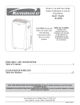
VOL. I
(MIRCOI
1011-9000
SLAM
1017-9000
SLAM
VIDEO GAMES
SERVICE MANUAL
t
o~0
of of
MIRCO GAMES
DIVISION OF MIRCO, INC.
Manufacturers of Coin and Non-Coin
Operated Amusement Games
1960 WEST NORT H L ANE , PHOEN I X , AR IZONA 85 0 2 1
TELEPHONE (60 2) 997 -59 31
PN 496
VIDEO GAMES
SERVICE
MANUAL
A Publication of Mirco Incorporated
Games Division
Congratulations on your purchase. We at Mirco Games take
great pride in producing the finest in coin and non-coin
operated amusement games on the market. Well maintained
equipment will provide greater pleasure for your customers
and increased profits for you. A thorough reading of this
manual will clarify our Warranty and provide product
knowledge and maintenance procedures.
This manual supercedes all
other manuals and warranties
expressed or implied therein.
(4-1-76)
TABLE OF CONTENTS
Page
Section
1
I
Warranty
II
Inspection
Installation
Cleaning
Top
Outside Window
Inside Window
Cabinet
Legs or Base
Picture Display Tube
Operation
Getting Inside the Game
To Start Game
Selecting Mode
Player vs Player
Player vs Game
Free Game
Figure 1-1 Back View of Monitor
III
Troubleshooting Guide
Normal Conditions
Adjustments to be Made
Game Points
Paddle Movement
Picture
Possible Computer Board Malfunctions
Score Related
Paddle Related
Tone Related
Free Game Related
Game Related
Play Field Related
Ball Related
High Intensity LED's
Coin Operation
Ball Speed Up
Pre-game Show
Video Related
Removal of Main Printed Circuit Boards
Replacement of Main Printed Circuit Boards
Figure 2-1
Figure 2-2
Figure 2-3
ii
2
2
2
2
2
3
3
3
3
4
4
4
5
5
5
6
7
8
8
8
8
8
9
9
9
9
9
10
10
11
11
11
11
12
12
12
13
14
14
15
16
TABLE OF CONTENTS (continued)
Section
IV
Miscellaneous Parts to be Replaced
Player Mode Switch
Control Potentiometers
Start Button
Monitor
Monitor Chassis
Audio Panel
Monitor Panel
C43 Capacitor
C47 Capacitor
Light Bulb
Figure 3-1 Monitor Chassis
Figure 3-2 Monitor Chassis
Figure 3-3 Audio Panel
Figure 3-4 Monitor Panel
Figure 3-5 Monitor Panel
17
17
17
17
17
17
18
18
18
18
18
19
20
21
22
23
v
Miscellaneous Problems and Possible Solutions
Coin Mechanism Related
Audio Related
Free Game Related
Control Lever Related
Figure 4-1 Control Lever
Paddle Adjustments
24
VI
Replacement of Any Item in the Game
28
VII
Removal of Parts
Top
Speaker
Free Game Light
Monitor
Paddle Control Lever Assembly
Illumination Lamps
Game Mode Rotary Switch·
Start Switch
Coin Mechanism
29
29
29
29
29
29
30
30
30
30
VIII Additional Information
Repair Costs (out of warranty)
Figure 5-1 Individual Control
Wiring Harness
Figure 6-1 Original Joystick Control
Harness (1011-9000)
Figure 6-2 Modified Pro/Am Control
Harness (1017-9000)
Figure 7-1 Cabinet Assembly
Figure 7-2 Cabinet Assembly
Figure 8-1 Monitor Schematic
iii
24
24
24
24
25
26
31
32
33
34
35
36
37
38
Some illustrations in this booklet are made possible by the
use of the Motorola Service Manual 68P65130A70.
To order additional copies, see your local distributor, or
write:
MIRCO GAMES DIVISION
Mirco Incorporated
1960 West North Lane
Phoenix, Arizona 85021
•
I
WARRANTY
MIRCO warrants the Goods to be free from defects in material
and workmanship under normal use and service for a period of
twelve (12) months from the data of delivery on all parts
except potentiometers, for which the warranty period is ninety
(90) days from the data of delivery. MIRCO MAKES NO
REPRESENTATIONS OR WARRANTIES CONCERNING THE EQUIPMENT WHETHER
EXPRESS OR IMPLIED BY OPERATION OR OF FITNESS FOR ANY PARTICULAR
PURPOSE, OR WITH RESPECT TO PATENT INFRINGEMENT, EXCEPT AS
MAY BE SPECIFICALLY MADE HEREIN. MIRCO's obligation under its
warranty herein is limited to the repair or replacement of
such parts which have been returned to MIRCO's plant a
Purchaser's expense and which examination shall disclose to
MIRCO's satisfaction to have been so defective and to shipment
of such repaired or replacement parts to the Purchaser f .o.b.
the shipping point. This warranty does not apply to any of
MIRCO's products which have been repaired or altered by unauthorized personnel or service facilities in any way or
which have had the unit serial number altered or removed.
Upon acceptance of the Goods, the Purchaser agrees to assume
all liability for any damages, and bodily injury which may
result from the use or the misuse of others, and to hold
MIRCO GAMES, INC., harmless from liability and claims arising
out of the use of the Goods by any person.
Parts returned for service must contain the game model and
serial numbers.
Please use the red repair tag for this
information. They also should be packaged to insure no
damage is incurred during the shipment and shipped to 1960
West North Lane, Phoenix, Arizona, 85021. The original
shipping carton is recommended.
-1-
II INSPECTION
Installation
1.
IMPORTANT - Do not plug unit into wall power
receptacle until inspection of game is completed.
2.
Upon receipt of unit, check out immediately for
damage. Mirco games are shipped in a carefully
designed package intended to prevent shipping
damage.
However, if damage should occur a claim
must be made with the carrier upon delivery of
the game. Storage of packing material is recommended in the event reshipment of the game or a
game part is desired.
Cleaning
IMPORTANT - UNPLUG GAME FROM POWER RECEPTACLE DURING CLEANING,
INSPECTION, OR WHENEVER REPLACING A PART, TO PREVENT POSSIBLE
ELECTRICAL SHOCK.
Description - The top is of a one piece laminated
formica.
The surface is resistant to scratches.
To help maintain the luster, occasional waxing
will help.
Scratches may be covered by using 'Old
English' furniture polish.
Cleaning - The surface may be cleaned with any
standard cleaner designed for this type of finish.
Outside Window
Description - The window used in the top is made of
break resistant 3/16" flow tempered glass.
The top
surface is highly resistant to scratches and chips.
Although scratching may result, shattering from a
sharp blow is not likely.
Cleaning - Daily cleaning of the window may be
accomplished using clear water and paper towels.
Window cleaners may be used; however, overspray
from these products will also remove wax or protective finish from the top.
It is highly
recommended that anti-static cleaner and a nonabrasive cloth be used.
-2-
II
INSPECTION (continued)
Inside Window
Description - The tinted display window is made of
break resistant acrylic plexiglass which is 16 to
20 times stronger than glass. Although scratching
may result, shattering from a sharp blow is not likely.
Cleaning - Cleaning of the window may be accomplished
by using any anti-static cleaner (such as Kleenmaster
Brilliamize, made by Chemical Products Co., Omaha,
Nebraska) and a soft non-abrasive cloth. If antistatic cleaners are not available, a mixture of Joy
and water may be used. The window should be waxed
with car wax (paste) after 15 to 20 cleanings. Hairline scratches or spider webbing can be removed using
Vestal Plus Polish (Vestal Laboratories, St. Louis,
Missouri, 63110). CAUTION: Window or other ammonia
cleaners must not be used.
Cabinet
Description - The outside surf aces of the cabinet are
covered with a mar-resistant wood grained vinyl to
insure long life and durability.
Cleaning - These finished cabinet surfaces may be
cleaned with any standard cleaners designed for this
type of finish.
Deep scratches may be taken out
using 'Old English' furniture polish.
Base
Cleaning - Mild soap and warm water should be used.
The base may be touched up using brown enamel paint.
Picture Display Tube
Cleaning - May be accomplished with a damp (damp only)
lintless towel. Do not apply liquid to tube--=--apply
liquid to towel firs~making sure it is only damp
before attempting to clean tube.
-3-
Operation
1.
Open front door with the key.
To change end of game score point from 11 to
15:
2.
a.
While you have the front door open
push the metal tab (hanging down
from the middle upper inside of the
door jam) to the back. This will
release the lid lock.
b.
While holding the tab back, push
the lid open and lock into place
with the lock-arm located at the
rear right hand side of the game.
c.
Select game point of either 11 or
15 by moving switch on the 3700
circuit board on your back left
(switch down for 11, upwards for 15).
The switch is normally preset at the
factory for 11 count.
d.
Unlock the lock-arm and carefully
shut the lid, giving it a little
downward push. Listen for a latching
sound - it should now be locked in
the down position. Give the lid a
sharp pull upward to make sure it is
locked before shutting the front door
to the cabinet. Place game in final
final location. Do not carry by top,
use cabinet body.
To start game:
a.
Close and lock the front door. Connect
to llOV 2-wire outlet only. Operation
of unit not guaranteed if ungrounded
2-wire adapters are used.
-4-
Operation · (continued)
NOTE: For those games placed in locations where
220VAC at SOHz is required, the following is
applicable. SWl located on the monitor chassis
must be placed in the 200V position.
The power
input cored must be converted for the same
voltage and applicable power source plug.
IMPORTANT: All games are equipped with a safety
interlock switch for your protection. The interlock switch allows AC power to the unit only
when the door is closed and locked.
~~
3.
Selecting Mode:
a.
A play field should appear within
moments on the display screen. Br~ght
ness, contrast a.nd volume are preset
at the factory.
However, location,
lighting and accoustics may vary,
requiring readjustment of these
controls (Ref. Fig. 1-1).
It is
recommended that adjustments other
than the ones i ndicated be performed
by a qualified technician.
b.
Select type of mode (i.e., player vs
player or player versus game):
Player vs Player
Select Pro (small paddles) or Am (large
paddles-.~Deposit one coin intO-the coin
mechanism. This will display one (1) paddle
for each player. Deposit a second coin for
one additional paddle per player (for doubles).
The first coin will cause the score to reset
to 0-0. Push "To Start" button, game will
commence immediately with a beginning serve
tone.
Player vs Game
Deposit one coin for one (1) paddle for the
challenger. Deposit a second coin for an
addit1onal paddle. The first coin will cause
the score to reset to 0-0. Push "To Start"
button - game will commence immediately with
a beginning serve tone. For Am (large paddles)
place knob into Am mode. (See---Section VIII #3)
-5-
Operation (continued
4.
Free Game
A free game is available only in the player
versus game mode.
Upon the challenger winning,
the free game light will come on.
a.
b.
c.
Select mode
Push the "To Start" button for the
second game.
The free game light
should remain on during the free game.
You cannot win a consecutive free
game on top of the first free game.
Only one free game is available per
the original game.
NOTE:
If the game does not operate properly, refer to
the Troubleshooting Guide to determine the reason for
the failure and steps that must be taken to correct
operation.
-6-
NOTE:
If game does not operate properly,
ref er to the Troubleshooting Guide
to determine reason for failure and
steps that must be taken to correct
operation.
CENTERING
RINGS
YOKE
i\:t -- ~\ ... ~\
-j "'" ~\
'~ ..
Pl
CONT
BRITE
VERT
HOLD
HORIZ
HOLD
Chassis Component Location Rear View
FIGURE 1-1
7
VOLUME
III
IMPORTANT:
TROUBLESHOOTING GUIDE
UNP~UG GAME FROM POWER RECEPTACLE DURING
CLEANING, INSPECTION, OR WHENEVER REPLACING
A PART TO PREVENT ELECTRICAL SHOCK.
Normal Conditions
1.
Partial numbers may be displayed prior to
new game. Game should reset 0-0 upon
insertion of a coin.
2.
A tone will sound at pushing the "To Start"
button after the insertion of a coin into
the coin mechanism.
3.
A tone should be sounded at every bounce and
score of the ball.
(The ball may be trapped
along one of the boundaries emitting a
constant tone while moving back and forth.)
4.
There are two (2) speed-ups of the ball during
play depending on how hard you hit the ball
and at what angle in the Pro mode.
(In Am
mode there is only one speed-up)
5.
Slight back and forth and/or up and down movement of paddle (ripping) in stationary position
is okay; also, the amateur type paddle will
collapse into the lower boundary.
Adjustments to be Made (if needed):
1.
Game Points
a.
2.
On the 3700 printed circuit board, there
is a switch. In one position it will let
the game continue to 11 points before
ending; in the other, it will go to 15
(as expressed on Page 4).
Paddle Movement
a.
For paddles not going to the side of the
playfield or stopping short of the wall,
on the 3701 printed circuit board there
is an adjustment potentiometer. See
"Removal of Main Printed Circuit Boards"
and Figure 2-1 (also Pages 24-27).
-8-·
Adjustments to be Made (continued)
3.
Picture
a.
Fuzziness can be adjusted on monitor from
the brightness, contrast or focus controls.
(See Page
b.
Vertical and horizontal holds are also
adjusted on monitor chassis.
(See Fig. 1-1)
Possible Computer Board Malfunctions
THE FOLLOWING MALFUNCATIONS WILL REQUIRE THE MAIN
COMPUTER BOARDS TO BE REPLACED (See "Removal of Main
Printed Circuit Boards", Page
1.
Score Related - 3700 Board
a.
b.
c.
d.
e.
2.
Paddle Related - 3701 Board
a.
b.
c.
d.
e.
3.
No reset to zero at beginning of game
(either side or both)
Partial and odd numbers (either side or
both)
Score does not display (either side or
both)
Score displayed continously (either side
or both)
Score erratic (either side or both)
Four paddles for one coin
Partial or odd paddles (either side or
both)
No paddles (either side or both) upon
insertion of a coin (score of 0-0 may
not appear)
Two paddles for two coins
(See "Miscellaneous Problems: Coin
Mechanism Related")
Tone Related
a.
b.
c.
- 3701 Board
An unusually long scoring tone (either
side or both)
An unusually short scoring tone (either
side or both)
No scoring tone (either side or both)
NOTE: Slight differences in length of score tone
(up to 50%) do not indicate a board malfunction.
-9-
Poss~ble
4.
Computer Board Malfunctions (continued)
Free
G~me
a.
Gives intermittant free game during
regular game
Gives free game, but no free game light
(see "Replacement of Free Game Light")
Gives free game light, but no free game
Give no free game
Free game light does not stay on during
free game
Paddles are removed after winning first
game preventing play of free game
Game will not end at score point during
free game
b.
c.
d.
e.
f.
g.
5.
Related - 3700 Board
Game Related
In Player versus Machine mode - 3700 board:
a.
b.
c.
d.
e.
f.
Backboard and guard appear but no right
paddle
Backboard, guard and right paddle appear
but right inside paddle does not appear
with insertion of second quarter
Backboard does not appear
Guard does not appear
No goal in back wall
Paddles disappear after winning free
game
In Player versus Player mode - 3700/3701 boards:
a.
b.
c.
d.
e.
f.
g.
First quarter does not give paddle on
right side
First quarter does not give paddle on
left side
Second quarter does not give paddle on
left side
Second quarter does not give left inside
paddle
Half or only part of any paddle displayed
Top boundary missing all or in part
Net missing
-10-
Possible Computer Board Malfunctions (continued)
5.
Game Related (continued)
End of . game - 3700 board
a.
b.
c.
d.
e.
f.
6.
Play Field Related - 3700 board
a.
b.
c.
d.
e.
7.
h.
No balls
Multiple balls
Erratic balls, jerky balls
Unusually high or low travel speeds
No angle to rebound off a paddle
Score doesn't change at time of win
Does not go through goal (during Player
versus Game mode)
Fails to bounce off walls or paddles
High-Intensity LED's - 3700 board
a.
9.
Multiple fields
No net or partial net
No video, but ball
Fuzziness (See Figure 3-5 for focus control)
Playfield light with black borders
Ball Related - 3700/3701 boards
a.
b.
c.
d.
e.
f.
g.
8.
Game ends on 1 or 5
Game ends immediately after start
Score reaches 11 or 15, then goes back
to 10
Games does not end when score on right
reaches 11 or 15
Game does not end when score on left
reaches 11 or 15
Game continues beyond 11 or 15
Under lid for the illumination of the
coin acceptor. LED's test okay, but
don't light.
(See Page 24)
Coin-Operation - 3700 board
a.
Related problems with number of paddles
appearing on playfield.
(See Page 24)
-11-
Possible Computer Board Malfunctions (continued)
10.
Ball Speed Up - 3700 board
11.
Pre-game Show - 3701 board
a.
12.
Pre-game show (except ball)
Video Related - 3700/3701 boards
a.
b.
c.
d.
e.
*No picture or just a flash on screen
at time of plugging in or unplugging
from wall socket
*White screen
Ball and/or playfield in bad contrast
Tube lights up, but no playfield
Vertical or horizontal hold or contrast
unadjustable from monitor chassis. See
"Miscellaneous Parts to be Replaced,
Monitor")
*Note: For (a) or (b) see "Miscellaneous
Parts to be replaced (Monitor, (a) and (b),
Pages 17 & 18. Check Ql9, Q20 or ICl first
before Slam Boards.
-12-
TROUBLESHOOTING GUIDE (continued)
Removal of Main Printed Circuit Boards
CAUTION:
1.
2.
3.
4.
Unplug the game first!
Unplug the game
Unlatch lid and lock in the full open position
Located on your left are the Main Printed Circuit
Boards.
Pull each of the four plugs out by
depressing both release tabs and pulling straight
out. CarefUIIY take the two (2) upper corners
and pull the boards straight up and out, lay
the boards on the Display Tube (using a soft
cloth covering the tube to prevent scratches
from the Printed Circuit Boards), with the
component sides facing upward (see Figures 2-2
and 2-3).
Fill out red repair tag and mail broken boards
and reapir tags to MIRCO.
fo~o'o' ~:~;~~:~~~;~~!!~·
MIRCO GAME REPAIR TAG
1960WESTNORTHLANE,PHOENIX ,AR IZONA85021
TELEPHONE(6021944·5578
ATTN: DAVE MASSEY
CUSTOMER SERVICE
NAME _ _""'--1:.LCIL.,,__--"""<.!.LL_LLI__ _ _ _ _ _ _ _ _ _
ADDRESS _~l~
d~
o=e<-~Ti~<l~
""~
r~-S~T_
_
~
_ _ _ _ _ _ __
CITY-STATE _~fl,,,t>1CLV-""''l""i./"'"-"""'li'E..,__-'LU~5"-'-"8'-'---------P.O. BOX NO ·---~~---- ZIP CODE
99cw 9
GAME SERIAL NO . - - - " " " ' 2 . . L . L _ _ __
MONITOR SERIAL NO. _ _ _ _ _ _ __
MONITOR PANEL BOARD SERIAL NO. - - - - - - - 5V - VS 102 POWER BOARD SERIAL NO. _ _ _ _ _ _ __
COMPUTER BOARD SERIAL NO.
( FOR COMPUTER BOARDS -
IB':f7oo
03500
tau -
FlOQ
"*'-rRO
PLEASE IDENTIFY BY CHECKING ONE OF THE FOLLOWING.)
03701
03702
0
OTHER
DESCRIPTION OF PROBLEM( S)
GB.m~
Qi
"5.~a:..'r.
,c:;:f.:;:;:;
G12a:i.e:.
&~~~z:
G.,,.~
7<i
Q-Q
M.
/'2-Q
( PLEASE REQUEST ADDITIONAL SHEETS AS NEEDED)
USE IN CONJUNCTION WITH MIRCO GAME ITEM TRANSFER TAG, IF NEEDED
RETURN, IN CARE OF _ _ _- ' - < . £ u z . L . = - - - - - - - - - -
SAMPLE REPAIR TAG
-13-
TROUBLESHOOTING GUIDE
(cont~nued)
Replacement of Main Printed Circuit Boards
Upon reinstallation of the Main Printed Circuit
Board, make certain you slide it into the slots
provided on either side of the game box interior .
(see Figure 2-1)
(SLDT5)
(5L..OT6)
COIN
ACCEPTOR
FIGURE 2-1
-14-
......
Vi
t0
N
tTl
~
0
c
'Tl
..._j
0
-
0
0
NOTES'!. INSTALL
2 . INSTALL
fTl
CJ
-
JI
--{
7- uJ
rn
l
_Q
\)
3
Q
0
--------"'-·-""·
-- --
I REQO ( 48
RI
ITEM 52 WITH QI.
ITEM 51 WITH Q2.
_Mn'_T__ _
:
- ~DI
C6
~
D"'
D".' .
~· .
, w~i1
~
~
'
1
, ·!I!
. ~ '
Cl
3.
~
i».. '. ~
~
,
C4
· ~
..
5
'), ,t
'
': . . '
I!*,!
~ ~. ~ ) ! ~f~· toDtl
I
:c
•
u'.q 1J ~Ou 1·u·0~L v (y,s'
l O!m~
~(· ~~~- mm1 : ~ · ~
u
>
· ~ ~f"~=~,.~1
'8
~ ~ : :·:l
J
~ v,
~
'
~
..
" ' ~'
11~~~;~~~.,,, ,i;;~;v- "~"'~.~-
. :.:
~I; '
'1 : ,
8
:.
,
:~G-1 ,
.
:_ t
Gf.
1
U
:
.•
.
c
~
I
..
.
:
f:L,''lf,..
·W
'.
'•
~· - "I
. ··.:I .:1
. · ·..
R444-·..
·:
'.'.
~
.
~
4
,',
Jss
'.
R2 .
s
·I 'e
. - .:'.!0 §.1 ._b
RIS
. ~ ' 1 -c~
',
ty_w. :·", ·_
UF_, .
~
•
~
C
---- ~·
.
C60
..
c
i ~ , ·· · ~u~tl ::i::(!Q1• ro· ·G -§o~
, : . - - ~ . - ~ , ..· ·~ .
;
I
• u
·~
· ~ C2 ~ ...~~
U~~
- (1 6
u ,
· :. ~~·. ~',!i
.i ~
~. :~
~
.n~;~
wi ~.,,1€~;
~ ~~
•'~·-1 -_,~. :_~5~0~~-;~ ·-~-Jr.o~ 1
'
,.r -~~: ':,
l
l
j
0
cg
2
~
~
WIRE
FO R/ 3 J\JN23}.i 11'
KfY
MI RC 0 GAMES I NC.
PHOENIX, ARIZONA
f;/14/15
DUET ED R40 f R+I- ~ODED
JUl'llPER WIRLtCO 502'> .
ECO
REVISlD 0\tDRl\\'ltt PEI\
I 4
llSSUE
:i,
DATE: JUNE 23,75 KPY
REVIS I ON S
INUMBER:
10 11-3700
FOUR PLAYER JOY STICK NO I
NOH
y
!Jj
0\
w
N
trl
:::0
0
e
'"r1
~
P1
u1
fj
-l 0
z
rn
7-
ao
3
0
(\
43
IV MISCELLANEOUS PARTS TO BE REPLACED OR REPAIRED
(if the following problems exist)
Player Mode Switch
1.
If the wires are not loose or shorting, circuit
boards are okay, but still:
a.
b.
c.
Player versus Player is unobtainable
Player versus Game i~ unobtainable
Neither position will allow a game after
money has been deposited
Control Potentiometers
1.
If the wires are not loose or shorting, but:
a.
b.
c.
Paddles move erratically to rotation
of levers
Set screws may be loose on pots
Pots may need replacing
Start Button
1.
If the wires are not loose or shorting, but:
a.
Fails to start game after money has
been deposited and switch has been
depressed
Monitor
There are two boards in the monitor, a small plug-in
SV board located behind the big black transformer
(henceforth referred to as the audio panel), and
an 8 11 x 5~" board plugged into the chassis with a
small bunch of wires f rorn the same board plugged
into the yoke of the picture tube (henceforth
referred to as the monitor panel).
(See Figures
3-1 and 3-2)
A.
Monitor Chassis
1.
A low 73V on monitor power supply will
give you a reduced playfield (in size) or
ripple throughout the playfield, or bars
in the playfield.
2.
No picture - check Ql6 or audio panel
3.
Contrast, brightness, verticle or horizontal
holds, or volume is unadjustable or partially
adjustable.
-17-
MISCELLANEOUS PARTS TO BE REPLACED (continued)
B.
C.
Audio "Fanel (See Figure 3-3)
1.
A low SV output will produce snow or haze
2.
No picture or sound, check Ql8, Ql9, ICl
(or Q20 on chassis)
Monitor Panel (See Figures 3-4 and 3-5)
1.
D.
C43 - Capacitor (See Figure 3-1)
1.
E.
If playfield
h~s
ripples or waves in it
C47 - Capacitor (See Figure 3-1)
1.
F.
Adjustments to this panel should be done
only by a qualified serviceman
If dark lines move slowly and horizontally
through the playf ield
Light Bulb
1.
No sound, or weak sound (see Page,31)
Figures 3-2, Item E 1, also see Page,31, #4)
-18-
\0
'Tl
Y'
tr1
:::0
5c
PLUG IN POWER
AUDIO PANEL
T4
PWR
TRANS
C43
020
R79
5V REG
SW1
R10
Chassis Compone'!t Location Top View
VIDEO BIAS
PLUG IN
MONITOR PANEL
T3
05
HORIZ OUT
09
VP12
N
w
w
tTl
~
c
5
'"Ij
'. ~
l .
(;>.-
.... . . . .
l ~~-·
. ~~ . "'
ORIVER N·
REG
014
?
AMP
020
ZENER t
-
.,
PJ/ · 41
Top View
C: •.GJ) >
+
019
A6G
5V REG DRIVER
018
P2V
AUDIO OUT
5VREG~
.·. .
IC 1
AUDIO DRIVER
017
AfiJ
•
I
-1-8
7
6
12
11
Power, Audio Panel Component Location
ill 6 BASE
ll16 COLLECTOR
ll15 COLLECTOR - t - - 10
I
5V SENSING
EMITTER~--
ll20 COLLECTOR
Q20
-----
SPKR - I - - 4
R82 VOLUME . ARM -
R82 VOLUME IHI SIDE
AUDIO INPUT
+
C50
R91
5.6K
---NW--
R77 100
----NW---
R78
1.BK
'
~20
0
3.JK
73V
REG
DRIVER
®
014
5'1 -s-'4•
---NN--
R76
R92
'
.R.9~
~~
AUDIO
DRIVER
®.~"f 1~~8
~--NH-!OK
Circuit Side
~
ll19
,~~
~
018
AUDIO
OUT
- .l(SOMFO
N
N
'T:I
.l::..
tn
w
~
c
5
SERVICE NOTES
To prevent damage to the board or foil when removing the circuit panel it may be necessary to pry up slowly, IN STAGES
around the edges as shown. Start at one corner and move all around the board keeping the screw driver tip against the chassis.
When installing, apply pressure at the edges near the pins. Do not force down on the components.
PANEL REMOVAL/INSTALLATION
N
VJ
Vi
VJ
:;:i:;
tTl
e
()
"'Ij
RlO
VIDEO
BIAS
TO
CRT
FILPIN8
VIDEO
OUT
aJ
TO CRT PIN 2
G1
TO CRT PIN 3
G2
R74
73V
REG ADJ
a15
REF
AMP
a5
SYNC
SEP
D7
as
AFC
HORIZ
PHASE
DJ OSC
DET
Monitor Panel - Component Side
R59
VERT
LIN
2
HORIZ
DRIVER
~·
T1
as
HORIZ
DRIVE
22 23 24
HORIZ
PULSE
SHAPER
U7
TO CRT
a11
R65
PIN 7 CATHODE VERT VERT
OSC-2 SIZE
a12
VERT
DRIVE
~--·'
.... 35
LJ
HORIZ LIN
--
• .,.. 31
, ,.. 32
D2
PULSE
LIMITER
L1
~HORIZ
SET
, ,,,. 33
~
, ..... 36
\i \
V
MISCELLANEOUS PROBLEMS AND POSSIBLE SOLUTIONS
Coin Mechanism Related
1.
Paddles don't appear, coins may be stuck
in coin mechanism, or black wire on coin
mechanism is loose.
2.
Two paddles for two coins - check for
loose wire on coin mechanism switch
(blue or orange).
3.
Two or four paddles appear on screen when
game is first turned on: blue, orange, and
biack wires on the coin mechanism trip
switch are shorting on coin box handle.
Insulate coin box handle with electrical
tape or put heat-shrinkable tubing on the
contacts of the coin mechanism trip switch.
Audio Related
1.
Score tone is fuzzy, may need speaker
replacement.
2.
Audio Panel may be failing
3.
Tone too loud or low, adjust on Monitor
Chassis
4.
No sound, see light bulb on underside of
Monitor Chassis. (see Page 20)
5.
No sound, see Ql8 on Audio Panel
(See Ql8, Page 20)
Free Game Relateq
1.
No free game light, LED may be burned out.
Control Lever Related
1.
Rotation of lever causes two or more
paddles to move, potentiometer leads
are probably shorted - inspect leads on
controls.
·
2.
No movement, bad potentiometer or see the
set screws for possible looseness, or a
wire may be broken (see Page 25)
-24-
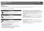
f.-llNc=.E.
SIDE..
LEFTS I DE CONTROLS
rv
(J1
RIGHT SIDE CONTROLS
DOOR SIDE
Figure 4-1
(top view)
These controls are wired in series. Therefore, if a wire
breaks on any control, it will affect the rest of the controls
left in that line; i.e., a wire breaks on #2, controls #3 and
#4 will probably not operate horizontally or vertically.
(Control #2 also may not work if two wires are broken.)
Number 1 and #3 controls are your 25¢ controls, they get the
most play and may be the major cause of control problems.
Number 2 and #4 are your 50¢ controls.
The left hand side controls are not interchangeable with the
right hand controls and vice versa, so when you order any
spares, please indicate which control(s) you want.
-25-
MISCELLANEOUS PROBLEMS AND POSSIBLE SOLUTIONS (continued)
Paddle Adjustment (against boundary)
1.
2.
Is for v ery small gaps
Is for larger gaps than 1/8"
la.
If a gap appears between a paddle and
the lower boundary, adjust the lOk
potentiometer (see Page 27 on the 10113701 logic board (located just under Pl) .
Locate paddle to .the bottom boundary, adjust
the potentiometer until the paddle just
touches the boundary.
2a.
Calibration - Horizontal Pot Control
(See Page 27) Remove the housing containing slam control from the table top
(but do not unplug it) by removing the two
#2 Phillips screws.
Remove the plastic
housing from the control by removing the
two 5/64" Allen Button Head screws. With
the joy stick assembly held in left hand
and game display set for four (4) players,
loosen the set screws on the potentiomter
shaft and manually turn the shaft until
the paddle touches the boundary it was
previously missing.
Locate the control
lever back to the point of the initial
problem and tighten the set screws; i.e.,
#4 paddle was against the bottom boundary
and up at the net (A-2 on Page 27) After
adju~tment of the pot shaft, push the
lever up to A-2 and tighten set screws.
Move the paddle around the court to see
if it now hits all boundaries.
Repeat
as necessary.
2b.
Calibration - Vertical Pot Control
The procedure is the same as horizontal
except for the following:
lOk pot on the 3701 board should be set
to midway point before starting its
calibration
lOk pot is used to add to or subtract
from the visual to mechanical balance
-26-
f-4 1NSE.
SIDE.
LEFT SIDE CONTROLS
P-3.
AL..
Ai. - - - - - - - . ,11.3
RIGHT SIDE CONTROLS
*'
'5TART
SWllCi-\
ig.3
DOOR SIDE
2A
A-2
A-3
Fig.2
©
©
27
VI
REPLACEMENT OF ANY ITEM IN THE GAME
For any item in your game that needs repair, we request that
you fill out one (1) fluorescent red 'repair tag' per item
with all the pertinent information and send us the 'repair
tag(s)' along with the defective item(s).
All items in any particular game (boards, monitors, etc.)
are to remain with the game in whcih they were originally
installed, except in time of repair. All items sent to MIRCO
will be repaired and returned with the assumption that the
item will be replaced into the original game .
This is of the
utmost importance, as any deviation from this method will
adversely affect the warranty .
-28-
VII
IMPORTANT:
REMOVAL OF PARTS
UNPLUG THE GAME FROM THE POWER RECEPTACLE
DURJNG CLEANING, INSPECTION, OR WHENEVER
REPLACING A PART TO PREVENT A POSSIBLE
ELECTRICAL SHOCK
1.
Prior to the removal of the top, open up and
remove the potentiometer controls, cables and
free game and illumination lamps and cables.
2.
Unscrew two screws holding the lid lock-arm to
the top. Unscrews the ten screws holding the
two hinges to the top.
Speaker
1.
Using a small Phillips head screwdriver, remove
the two screws diagonally placed on the speaker
frame.
Pull out.
Free Game Light
1.
Remove two screws from retainer.
Pull sideways,
parallel to glass to remove.
To replace, slide
retainer sidways, parallel to glass and install
two screws.
Monitor
1.
Remove MP4 wire connector, pull monitor
up and out. NOTE: Connector will come
by depressing both release tabs. Also,
be placed back into the monitor in only
because of the connector mold.
straight
out only
it can
one way
Paddle Control Assembly
1.
2.
3.
4.
Open top
Remove two ~hillips screws holding the black
cover (containing the lever control) to the
inside of the top.
Unplug .the green multi-cable plug running to
the control assembly.
Remove assembly from the lid (for calibration
of control lever, see Page 26).
-29-
'I
REMOVAL OF PARTS (continued)
Illumination
1.
L~mps
For coin mechanism, remove plate inside the
lid held on by two wood screws.
Game Mode Rotary Switch
1.
2.
3.
4.
5.
6.
Loosen nut holding switch to top
Push switch down or in and remove from
inside
Separate switch from ground braid
Exchange wires from old switch to new
switch one for one. If new switch is
not available, mark location for reinstallation
Insert switch through ground braid, and
place in panel
Install lock washer over switch and tighten
nut (do not allow body of switch to rotate
as nut is turned)
Start Switch
1.
2.
3.
4.
Twist switch body (under top) approximately
180° and pull down
Remove wires from switch terminals and
connect to new switch one for one
Position switch in top
Twist switch body approximately 180°
onto tab hanging down from the underside of the top. Let go of switch and
it should be connected
Coin Mechanism
1.
2.
3.
4.
5.
6.
Remove ground braid from rear of frame
Remove mounting screws
Pull harness through front of door and
change wires one for one to new mechanism
Connect wires to switch and position
mechanism in door
Bolt in place and connect ground braid
to rear of frame
Turn power on and check operation
-30-
VIII
ADDITIONAL INFORMATION
1.
A coin counter can be installed by connecting two
purple wires lying by the speaker with butt-connectors
on them, to either lead of the optional coin counter.
Secure coin counter in an upright position on the
floor left of the white pushbutton interlock switch.
2.
"Brightness" should be kept in the Off position
(extreme counterclock wise) on the monitor. Use
the control as illustrated in Figure 1-1. Bring
the picture into focus using the contrast control
(Figure 1-1) .
This process will increase the life
of your tube.
3.
Player versus Game is in Pro mode, for Am insert
quarters as usual, push "Push to Start"switch, turn
mode switch to Am.
This will give you double paddle
size and slower-Speed.
4.
El (Page , Figure 3-2) is a light bulb. For speaker
protection, if this is burned out, you will get no
sound.
(It is normally "Off", only during tones
does the bulb light up.)
5.
To tighten control movement, install (2) wave washers
per control. Part Number 7150-2501.
Eight (8) washers are needed per game, one set (8)
price is $.50.
0
0
Install
(1) here
Install
(1) here
-31-
ADDITIONAL INFORMATION (continued)
Standard Repair Prices for Out of Warranty Games
Item
Description
lOll-3700
8 Grid - Logic P .C. Board
lOll-3701
10 Grid- Logic P.C. Board
25.00
lOll-3000
Slam Control Assembly
10.00
lOll-0001
Monitor Panel P.C. Board
25.00
lOll-0002
5 Volt Monitor P.C. Board
15.00
10ll-XM501-10
Monitor
45.00
Cost
$ 25.00
Shipping is to be paid both ways by the customer. This
list of items and repair costs is subject to change without
prior notification by MIRCO GAMES.
-32-
w
w
reproduction
may
be
~e
of
tliis
(lo
14n))
---- - ORANGE
·--
A"T POT
.
BEFORE STRI PPING.
CON"'-l .
VPv?-- ·---
VL
HL
VP+
- -vp
-.--,.
HP +
HP+
HP -
HP-~
FUNCTION
-
E N D , SIRIP A-L L. WI RE':> .1'2. A.I
2. WIRE LENG THS ARE ACTUAL DIMENSION S
3. SCALE: NONE
4 . TO L : .><x~ ± .O '=:.
RF·2
i?z -2
--- "Rz - i
. - "Ri. --:t
Rz.-:3--
R2 -3
-
P5-6
P5-5
-P5-4 - -
- -P5:x
-
-·- ---
RI - I
RI- I
i!.T.:3 . -
TO
------ 6.62- - - - · ·
~ R1-3 - -
~
~l
I
10 -
~/.Cl?
-------· -·---··
".:
E.1'-lD .
-
l ·_ -462~-z~-=-~
I
P5-B
P5-7
P5 - ~~ - ~-
p5.2 ·--7i.<so- - -- -P5 -/
- ·1wa ·io.oo
10.00
10.0 0
·--- 11.00
//.00
f l.00
.
·:05-ia- ·
FROM
WIRE LIST .
LE:1GTH
-. 12
10.00
--tiQP~
/. STR/ PALLWIRES .18
NOTES:
10
8LAc°K ____
YELLOW
8
9 -
-7 - -
WHT/ RD
WH'T, ' RD
··----RED
RED- BLACK
- J:'Vµ T/ BK
I-
2
3
4
!-----'- 5
6
COLOR
wH r/ eK
I
1
WIRE
NO.
W8
.
W6-W:ow;~
W5 - - f
-~
----- · -F:--~~~ c
,,. -.
. - WI - W2
//
, -W9
'~~~I
EE
.
,- W4
~'-- _ _ .
~~--
lo ,,,----.
1 W3
-·----- ---·-····- - ----
$XD€R { TYP) - - - - ,
----··
D~\\<O ~ -----
~(Cf<ZW..--,
Bo\..\NP~'-/
without the expr• written
permiaion of MIRCO, INCORPORATED
Of
" PROPRIETAR Y INFORMATION .. No use
d ocument
PIN
11 /
U bi-\T
?UjG
ISI
ON
ISSUE
II
MIRCO GAME S, INC.
P HOENIX. ARIZONA
E L E ...':>ED "TO "'\ FG.
4/li / I ':> ..)L..1"f\
R EV
1011- 0 2 06
DATE : 4 ·1075/ C.M.
NU MBE R
CABL E ASSY,
.JOY STICK
L?e~w
- - 112
REF
'
'
"PROPRIETARY INFORMATION" No use
or reproduction may be in.de of this
docum«!t Without the express written
permi•ion of MIACO, INCORPORATED.
17.00
T
1,.00 - - - - - - - -..-~
--r
/.00 TYP
2i lo-
WIRE LIST
WIRE
NO.
I
2
3
4
5
6
7
8
9
10
II
12
13
14
15
16
~/-7-
18
19
20
21
22
23
24
*25
COLOR
WHT/RED
WHT/REO
WHT/R£D
WHT/RED
WHT/BLI<
WHT/BLK
WHT/Bi..K
WHT/BLK
RED
RED
RED
RED
BLACK
BLACK
BLACK
BLACK
-WHT/ORG
ORANG£
WHT!BRN
BROWN
WHT/YEL
YELLOW
WHT/GRN
GREEN
BLACK
26
,_Q.__ _
28
*29
30
31
32
33
34
35
L£NGTH
I . /2
·-
BLACK
_§j,_~9K__.
BLACK
BLACK
WHITE
VIOLET
GRAY
BLACK
BLACK
BLACK
FROM
.P/-4
I
TO
FUNCTION
t.15-7
c.!7-7
t.19-9
c)l/-10
c.!5-9
c.!7-9
c.!9-7
Jl/-8
J5-5
t.17-6
t.19-3
t.111-4
c/5-3
c/7-4
c.!9-5
HP+
I
HP+c.!5-8
I
HP+
c.!7-8
HP+
c.!9-10
i
HPP!-16
!
HPJ5-IO
HPc.!7-10
I-IPc.!9-8
VP+P/-2
28.00
VP+c.!5-6
/5.00
VP+
t.17-5
19.00
VP+
c.!9-4
15.00
VPPl-14
28.00
VPc.!5-4
15.00
VPt.17-3
19.00
VPc/9-6 . ·-'---J/1~--15.00
. 28.00 ____ -Pl-II
J5-/
HL
I
J5-2
28.00
Pl-6
VL
J7-/
4/.00
Pl-9
HLM
c/7-2
VLM
4/.00
P/-8
I
i
P/-7
t.19-1
58.00
HR
I
I,
58.00
J9-2
VR
Pl-:_(2___
!
Pl-I
JI/-/
71.00
I
HRM.
71.00
<l//-2
P/-/2
VRM
28.00
Pl-15
i./6
GND
15.00
i./6
c/8
GND
t}/0
GND
_L9.-QQ ---- ·-- _..!!_§__ ·-·--·
<112
15.00
GND
--- ·- __r!.112.. ... -..Pl-15
80.00
GND
SWl-2
PLAV£R VS G~
80.00
P/-5
SW/-/
p/-::3- - SWl-3
PLAY£R VS PLAY£R
80.00
- -- P1-13 - SW2-2
N.O.
83.00
3 .00
SW2-I
SWl-2
GND
TERM
GND
SWZ-/
4 .00
4-.00
TERM
TERM
GND
28.00
15.00
19.00
15.00
28.00
15.00
/9.00
15.00
I
I
--
I
NOTES:
I. STRIP ALL WIRES .18 EXCEPT <15, J7,J9 AND JI/.
2. WIRE LENGTHS ARE ACTUAL DIM£NSIONS BEFORE STRI PPING.
3. W25
WZ9 ARE TWO WIRES CRIMPED ON ONE CONTACT PIN.
4. MARK "p1· ON HOUSING WITH INDELIBLE INK, APPROX. AS SHOWN.
5. INSTALL CABLE TIES AS R£~'D.
6. STRIP ALL WIRES ./2 FOR tl5,<l7,.J9 ANO JI/.
7. SCALE: NON£
*
t
De.\b\N6..L
JOY STICK
CONTROL CABLE
NUMBER
ISSUE
1011-0202
DATE>4·1115 . C.#.
RE V I S I O N
Ml=C...
~ .Jl.M
4111 /1
~ -
MIRCO GAM£S, INC.
~--------------~~-------------~·- --------------------------------------------------------_,.~f'fl<~
- ~0~£~N~/~X..z...:..A~i'f.~IZ.=Q-'0:.:...:.:..~~,
34
oN
Ta t..oc i<'. IT
•
\I
WIRE LIST
WIR£
NO.
I
2
3
4
5
6
7
a
9
10
II
12
13
1415
16
_1_1_
I
COLOR
I
WHT/RED
WHT/R£D
WHT/R£D
WHT/R£D
WHT/BLX
WHT/BLK
WHT/BLK
WHT/BLK
RED
I
R£D
RED
BLACK
BLACK
&ACK
/6.00
19.00
15.00
·-
--wiiTlOiiG-
18
19
ORANG£
20
BROWN
:t.12
28.50
16 .00
/9.00
15.00
28.'50
16 .00
19.00
15.00
I:
FROM
P/-4
u5-e
<11-e
J9:IO__
Pl-16
J 5-IO
Jl-10
J9-8
Pl-2
J5-6
i.17-5
J9-4
Pl-14
J'5-4
Jl -3
I
I
28 .SO
/6 .00
19.00
15.00
28.50
R£f)
BLACK
LENGTH
- - -ia~sa ··-- -
----
cJ9-6
?!~Ii
28.50
Pl-6
42.00
Pl-8
I!
II
TO
i.15-7
Jl-7
u9-9
c)/ /-10
J 5-9
cJ7-9
J9-7
c)//-8
J5-5
Jl-6
J9-3
'
i
I
I
!
I
i
NOTE TAB FOR
ORIENTAilON
FUNCTION
HP+
HP-r
HP+
HP+
HPHPHP-
I
I
HP-
VP+
VP+
VP ..
VP+
VPVPVP_ V
_P______.
i.111-4
c/5-3
i/7-4
u9-5
~
~ uw
·---y;i-:6 - -- ··· - -J5--- 1 - - _71l____
I
V I ~ \'.
B-B
NOTES:
I. STRIP ALL WIRES .18 EXCEPT r.J5,J7,J9 ANf) JI/.
2. WIRE LENGTHS ARE ACTUAL DIMENSIONS 8£FOR£ STRIPPING.
3. W25 ; W29 AR£ TWO WIRES CRIMPED ON ON£ CONTACT PIN.
4. MARK ""P l" ON HOUSING WITH INDELIBLE INK, APPROX. AS SHOWN.
5. INSTALL CABLE TIES AS RE(i)'O.
6. STRIP ALL WIRES .12- FOR J5,J7,.J9 AND JI/.
7. SCALE: NON£
8 . MARK " PPl" f>\S '":oHOWN WITH \l\lDELIBLE INK .
*
J5-2
VL
J7-/
HLM
J7-2
VLM
u9-I
21
WHT/YEL
59.00
Pl-_7_·- - - - +
- - - - - - +HR
- - - - - - -'
!
J9-2
VR ___ ~--------------------------------,
22
YELLOW
5e>.oo
-+- Pl-:_(Q__
_;__.!.Cl:__
JI/-/
HRM
l--2_3_-+-_W_H_T~~-G~-'-N-+-_72_._o_o_--11 _ _P_1_-_1 _ _+------+----'-~---1
WIRE L\ST
cJ//-2
VRM
24
GR£EN
72. 00
___
P_l-_1_2_ ___.______
·- ·- - ------·--. .J-----.-------r------.,..-------,-----....--- - - ---i
•25
BLACK
29.00
Pl-15
___
u'_!?._
GND
COLOR
FROM
LEN<;Tl\S !: .12.
TO
FUNCTION
26
BLACK
16.00
i.16
cJ8
--GND° ________ WIR.E
NO
WHT/BRN
-~.00---fii.:"9---
reo/P.t-A
I
27
'28--
* 29
BLACK
-- -8L)~(£
BLACK
30
WHITE
!31
VIOLET
32
GRAY
?:i7
-
_ __ ·-
19.00
J8
JIO
··75:00-·-- -- cJ!O ·- - --· ___ J/2 ___
44 .00
3b . 00
3i;, .oo
44.00
·--p;;-:-;5--
sw:i-1
- ·:sws-
·--
se.oo
CONTROL CABLE
NUMBER
!()/?-OZD -Z
---1---~1-------+-----+------+------+--------1
GND
4-0
1'>W3-"2.
BLACK
.'50
SW':.-~
JUMPt."R
- -- ~G,
~
N
~D~---+--~--~~~--+--~~--+--~~-1---~~~---+-~~~~---<
SLAC K
'SW4-I
SW4-~
41
.75
J UMPE.R
- C.- - - - - 4-2.
SOLDER
··_G_N._D
_ __ - + - - - + - -BLACK.
- - - - - 1 - - - - -2.00
' - - - - + - - -'$W3
---1
- ' - - - WG
' - - - + - -C7ND
-'-------1
OATE:4·1l75/C."1
IISSUE
7
R E V I S ION
P!-~-- -1-2-~~~AYER ~-~!!!-
Pl-3
- -Pl-13--
-
~B.00
Pi:,- 4
Pl3- I
WH/(-,Y
SB .00
Pl~ -
Wl-\/BL
ae.oo
BU.CK
BLUE.
-~s-=c--
N.ODIFlED
JOY STICK
2.
P 13- 3
vs
N.O.
Pl.AY£R
N .O.
-·
SW4-2.
SW4-I
'SW4-C
io I\- 01-C'2-
-
SW3-C.
°RE?Lb.C:..E~
PLAY'CR
-
( PR\C...~ \~
-
Tl-IE
G-ND
VS G-AME1L
PRO/AM OUT
PLAYER V~ "-AME
""-P..fnE:.)
MIRCO GAM£S, INC.
PHO£N/X • ARIZONA
35
" PROPRIETAR Y INFORMATI ON " No use
Of
r.production m1y be ~e of this
document without the eicpress written
permission of MIA CO, INCO RPORAT ED
1-4\ NGE.
SIDE.
NOTES:
I. LED CABLE Ass'Y. (ITEM 16) CONTACTS TO BE INSERTED INTO P4 HOU51NC:i
(ITEM 15) AS FOLLOWS : BLK WIRE TO P4-I , BLK WIRE TO P4-3 AND RED WIRE
TO P4-2 .
2. WHEN MOUNT I NC:i LEDS (VIEW H) (ITEM 15), PUSH LEDS THRU HOLES AFTER
. ADDI NC:i BUSHING AND RETAINER . BEND LEADS TO FIT ROUTINC;i.
CAUTION: LEADS ARE BRITTLE,GARE MUST BE TAKEN .
3 . TO MOUNT INTERLOCK A5SY. (ITEM 9) ,SLIDE REAR. OF COVER UNDER PREAOJUSTED SCREWS (AS SHOWN IN SEC l'ION 0 - D) AND MOUNT FRONT US! NG
AGG ESS HOLES.
·
4 .IF COIN COUNTER OPTION IS USED,CRIMP TWO BUTT CONNECTORS (YIO
WIRES) TO BU<. WIRES ON GOUf'..ITER. MOUNT COUNTER TO WALL OF CABINET
USING TWO NO. 8 SHEET METAL SCREWS i I/ 2 LON(i.
5 .ITEM 24 MUST BE TIGHT A(iAINST INTERLOtK SWITCH . TERM! NAL GANNO-T
BE EXPOSED.
6 .INSTALL CABLES APPROX . AS SHOWN AND FASTEN IN PLACE WITH TIES
(ITEM 22~ . STAPLE. TIES TO CABINET.
LEFT SIDE CONTROLS
7. 00 NOT TRAP WIRES BETWEEN CABINET AND DOOR.
RIGHT SIDE CONTROLS
8.PLACE ITEMS 3B AND 39 IN COIN .BOX PRIOR TO SHIPPING .
9 . CUT ITEM 6 IN IB INCH LEt-JGTHS AND STICK TO ITEM I AS SHOWN
IC.MOUNT THE C:iROUND TERMINALS IN BETWEEN THE SWITCHES AND
THE DOOR.
I I.GUT ITEM 7 IN I INCH LEN~THS AND STICK TO ITE.M 12 A.5 SHOWN .
12.FINAL ADuUSTMENT OF THESE CONTROLS SHALL BE DONE IN THE FIELD.
13.JOY STIGK CONNECTORS SHALL BE MARKED RIC;iHT OR LEFT SIDE. AT
SUB A55'Y. LEVEL .
14.SCALE: 1/4
'.J IE.W
5E.E. 514
DOOR SIDE
H
'2.
19
D S EE.
'5142-
19
LOCATE FAP.SIOE
OF DOOR APPROX .
AS SHOWN
27
K
MONl'TO R
su PPU E.D
c~e, 1NE.T
'::>14 1E.LD
WI TH
CAB/N£T ASSY. ,
'5L,O.,M
'M
ISSl.IE:
1011 -4000
I
DAT£ 16 JUNE JLM
RE: VISION
RE.LE.l>.5'E.D "10 IV\l'C,,
<./'2. 1 /"lS
~1...N\
6
NOTE 9
MIRCO GAM£S,INC.
PJ.10£'NIX ARIZONA
SHC'E:TI OF2
36
"PROPRIETARY INFORMATION " No use
or f't!Production may be mM:le of this
doturnM'lt w ithout the exprns written
permi•ion of MIRCO, INCORPORATED
BUSHINGi
29
GRAY WIRE
2 REQ' D.
29
2 PLS
YELLOW llOT
REF.
RETAl~ER
NOTE 2
5
2 PL5.
VIEW H
FP.OM SHT. I
SC.ALE 1/1
YELLOW WIRE
6
REF.
30
2 PLS
29
2 REQ'O.
R~~BUSHIN~
SERVICE
LOOP
14
REF.
RETAINER.
SECTION J-J
L
12
PARTIAL SECTION
REF
D- D
PARTIAL
FP.OM SHT. I
15
SECTION
FO.OM
REF.
~HT .
E-E
I
5C .. LE: 1/1
SECTION C-C
FO.OM 5HT. I
SERVICE LOOP
14
.
REF.
( l>.DO CABLE Tl ES AS
NEEDED)
7
REF.
NOTE 11
NOTE
12
MONITOR MTG.
DETAIL
32.
35
CLEARANCE
HOLES IN
BOTTOM OF
CABINET FOR
ADJUSTMENT
V IEW G
PARTIAL VIEW K-K
FP.OM 5HT. I
SCALE'. 1/1
BLK
SEE VIEW F
ORN
CABINET AS.SY.,
5 Ll'--lV\ TM
SECTION B-B
FO.OM SHT I
tSEE
VIEWG
22
9
NOTE 4
NOTE CO
24
NOTE 5
BLU
5CALE: 1/2.
NUMBER
ISSUE
I
OAT£ 16 JUNE JLM
REVISION
1011-4000
RE.1..El>..":>E.D TO "'\FG
/27/,<;;, .:,L<'I'\
GREEN WIRE
POWER. CORD
(REF.)
SECT ION A-A
FR.OM !MT . I
MIRCO GAMES, INC.
Pl-IOENIX, ARIZONA
SCl\LE: 1/1
37
MONITOR
El
023
::..::
~
~
~
AC-LO
Pl-9
AC-HI
J-1
+
C2
}OMF
WHT
BLI
iii
COMMON
Pl-7~
Q5
SYNC SEP
A5U
+30V
36V P
V
+30V
o?'
OZY
SILVER CAP
OR ; SIDE
H. V. RECT
0
0
€0
DlAG 63D65165A88-
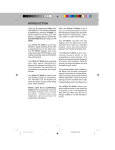
Schematic Diagram
38
I
I.
f .
/
I
'~ )
KVBDOA
TO NO.I
AUDIO MODULE
;;::;.;,i;..;;;;.....--.,.c-.-- +isovoc
h
I
VIDEO
PREAMP
, 60V pp
.015 RI? -
I
I
111111111••
+73V +150V
C9
Rl4
VIDEO
PIO
AC POWER
SOURCE
10
1
INPUT
0.22
•
:
[email protected]. o
+5.DV GNO
R6
500
CONTRAST
l
TO +5.0V
POW ER
SUPPLY
~C IR CUIT
'=-'CARO
l
l __ -- _J
R84 150
P5*
-b
017 ABW
REG UL ATOR
+73V
I
'------1---_._~t----'-'-=---'
f --S--*---P-* - - - - - - - '
1
I
2
2
I(
BlK
i
GAN
i
3
~2(
I
I
i_
IWHT
I
I
L
GAN
I
~
I
2
2
---!----+--'
{JI 1. .
CHAN. 2 AUDIO IN•
j
POWER SUPPLY
TO N0.2
AUDIO MODULE
I
l
l -- --
CHAN. I AUDIO IN.
CID
GNO
,
PLJ*
I
P4 *
v
3.9K
...
COMPOSITE
VIDEO
INPUT
I
~---+---+------'
_J
I
FROM
I
SUPPLY
4--< ;6~EVR
AN
C
~ CIRCUIT
__J
CARO
GRN
TO +5.0V
POWER
SUPPLY
CIRCUIT
CARO
mr~
1. UN.EU OTHE'Rffl!E N:>CATf0 1 Al,l "ESIHORJ ARE N OHMS,
~~~~ l~ ,.:~, cti:~C1;g:sC~E';.E~;rc,::~
r
011
* 02Y
@A£1"f'EfENTI MALE ,... ON Cl'IC\JIT CAll'Ol:SL.
AE"P"RESENTI JOOCETlllnrEMALE l'lt\I COfH"CT'M'.)N.
fo
~ f!IE'll'RE!£NTI 11\.UGtPll~AlE ,... CONNECTION.
=~~~~~~~~~T
•
-0
~
2.
TO
AE"'E!E"'TS CC>t*ONENTS THAT ARE CHAS!IS MOUNTED
C~T
L
R24
15DK
CENTE"-
lW
VOl TAG£ M"AOfNGS A"'E :t:l01!l.
S. A.C. WAYEl'OAMSt
R25
3. 3K
""
VIDE O ....UT CONhECTOR l"l.
CON TfllAST' CC>tllTROl IRel
AOJUSTE'D TO 0.lVP'-1" VIOEO SIGNAL AT DASE OF 02
1$££ NOTE 11..
M'AOJUST HEIGHT CONTROl At«> AO..(JSf
WIOTk COil SO A.ASTER TO'JCt-ES EDGE OF CRT SCREEN.
F RASTER IS ftAESENT.
WAVEFORMS VARY frlTH ASSOCIA TEO
CONTROL SETTINGS.
.ODS
E B C
t80T \llEWJ
05 18 1 19,20
E~
0~
?"-- c
B
!BOT VIEWI
09,15,17
+
20~·
+ C320
R34
~D
3.3K 1112w
~ ~
I,.,. VIEWI
tPIN VlfWt
P2
. S2
-t 0.ISY ,.,. V
E B C
v
lBOT VIEWI
All OTHERS
~.
G K
v
!BOT VTEWI
012
C31
+150V .Ol
R43
+73V
~
l'O 2 . !5Y ,.,. Y
010
A05
. DDi
- C32C
VIDEO SIGN1'l .ISVP'-P TO 2.ISV,-1' APf'l.IED TO COWOSITE
llHlHll
R26
lOOK
1
1.0
1' WA\IEfle>f'M TAKEN PJtOM '<)INT INDICATED TO GftOUNO
ro£ ()fl 111171.
0.C. VOl TAGU TAKEN WITH AE5'£CT TO CHASSIS ~
NO JGNAl N'UT.
HEIGH?" CONTlltOl SET T O MECHANICAL
PIN~
HEATER
VOL TAGE
cOR Vl
Cl5
CAROi.
WAVEl'Of'M TAKEN P'AOM piOfNT INDICATED TO Wl'EWlllAI"
P'IN"lll-2"'.
i&.
2V ,., V
~F-
"'fpft£SE"lT! ORIG~ OF VOi. TAGE N>ICATEO.
INOT ON A
S. f
CONNECTK>H TO AN
VERTICAL
z
l z
[Q]J
!@@@)
IPIN VUll
ll'IN VIEWI
P3
P4 15
3
R79
56K
l
il_
+73V
+12V
M5010-155, M7010-155 - Diagram Schematic
TOPI J
.
"
AC
~
r-AC INPUT
FROM SEC.
OF PWR
XFMR T3
1
I
I
I
I
I
LQ!,.,..Q.E
~
CIRCUIT
CARD
REGULATED
0201
7634
(HEAT SINK
MOUNTED)
40.ev
+
+c201
@--c.J>:_,____ __..
c203+
R204
470
1/2W
15000
F201
7A
t;i~
MONITOR
0201
I
I
I
AC
---,
100I
R206
4K
R201
68K
1/4W
+73V
{-<
-<re+--,.L
GND
'-"
-:- C202
.001
<(;
+5 Volt Supply - o,·agram Schematic
>--
TO PIN 6 OF P1
REGULATED
+5 .0V AT 30A
_OUTPUT
_I®>--
TO PIN 3 OF P1
w
0..
w
<(
<(
w
u
~
~
a:
ti; ::c
'11""9
N
0
w It)
z co
<(
...J
<(
z
0
cJ
J:
I-
CJ
3: 0
0
(0
N
z a: a:
0 <(
en" z
w I- x
:E U) z
<( w w
(
I
I
I
I
I
I
I
(.
I
I
I
I
CJ
a:
:E
0
en
'11""9
J:
~
ZIP _ _ _ _ __
P.O. BOX _ _ __ __
GAME SERIAL NO. _ _ _ _ _ __ __
GAMEMODELNO. _ _ _ _ _ _ _ _ _ __
Normal Warranty
D
Extended Warranty
(enclosed payment)
•
THIS CARD MUST BE RETURNED TO MIRCO GAMES, INC., WITHIN FIVE (5) DAYS OF PURCHASE
TO MAKE WARRANTY EFFECTIVE.
0
For $75.00 your warranty will be increased to 2 years on main circuit board(s) and Monitor.
Please check below:
WHO IS PROVIDING LOCAL SERVICE ON THIS GAME? _ _ _ _ _ _ _ _ _ _ _ _ _ _ __
WHEREWILLGAMEBEUSED?~------------------------
NAME OF DISTRIBUTOR - - -- -- - - - - - - - - -- - - - - - - - - - - -
WHERE WAS GAME PURCHASED? _ _ _ _ _ _ _ _ _ _ _ __ __ _ _ _ _ _ _ __
CITY & STATE
STREET ADDRESS
NAME ~-------·~------
PURCHASE DATE _ _ _ _ _ _ _ _ __
Parts returned for warranty service must be packaged to insure no damage is incurred during the
shipment and shipped to 1960 West North Lane, Phoenix, Arizona 85021. The orig inal shipping
carton is recommended.
Upon acceptance of the
Purchaser agrees to assume all liability for any damages, and
bodily injury which ma ~~"from the use or the misuse of the equipment by the Purchaser, his
employees or others, an
~Yo ld MIRCO GAMES, INC., harmless from liability and claims arising
out of the use of the Goods y any person.
Gqod~e
MIRCO warrants the Goods to be free from defects in material and ~rkmanship under normal
use and service for a period of twelve (12) months from the date of delivqr\.)n all parts except potentiometers for which the warranty period is of ninety (90) days fr~f.e date of delivery . MIRCO
MAKES NO REPRESENTATIONS OR WARRANTIES cGL_U~ NING THE EQUIPMENT
WHETHER EXPRESS OR IMPLIED BY OPERATION OF ~~OR OTHERWISE, INCLUDING
THOSE OF MERCHANTABILITY OR OF FITNESS FOJ\.~ Y PARTICULAR PURPOSE, OR
WITH RESPECT TO PATENT INFRINGEMENT, EXc~is -As MAY BE SPECIFICALLY MADE
HEREIN. MIRCO's obligation under its warranty h~~,n are limited to the repair or replacement of
such parts which have been returned to MIRCO's ~c\Q): at Purchaser's expense and which examination
shall disclose to MIRCO's satisfaction to have~\n so defective and to the shipment of such repair
or replacement parts to the Purchaser f .~~'ii) shipping point. This Warranty does not apply to any
of MIRCO's products which have befll ~"ired or altered by unauthorized personnel or service facilities in any way or which have had~~unit serial number altered or removed.
WARRAN TV
MIRCO GAMES, INC.