1
Donated by John & Susan Hansen - For Personal Use Only
L-LINE MOTOR TRUCK SERVICE MANUAL
TRANSMISSION
Index
1
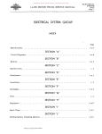
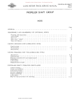
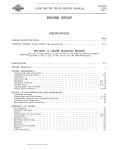
TRANSMISSION GROUP INDEX
SPECIFICATIONS
SPECIFICATIONS
SPECIFICATIONS
1
2
(TRANSMISSIONS)............... .............. ....
(AUXILIARY TRANSMISSIONS) . . . . . . . . . . . • . . . . . . . . . • . . .
GENERAL INFORMATION
Driving downhill . . . . • . . . . . • . . • . . . . . . . . . . . . . . . . . . . . . . . Overdrive . . . . . . . . . . . . • . . . . . . . . . . . . . . . . . . . . . . . . . . . . . . . . . . . . . Overload • . . . . . . . . . . . . . . . • . . . . . . . . . . . . . . . . . . . . . . . . . . . . . . . . . . Shifting . . . . . . . . . . . . . . . . . . . . . . . . • . . . . . . . . . . . . . . . . . . . . . . . . . . . Starting . • . . . . . . . . . . . . . . . . . . . . . . . . . . . • . . . . . • . . . . . . . . . . . . . SECTION HA" (HDS)
Models L-lIO, L-120
Disassembling and reassembling. • . • • . • • . . . . . . . . . . . . . . . • . . . . . • . . . . .
Gear shift diagram . . . . . . • . . . . . . • . . • . . . . . . . • . . . • . . • . . . • . . . . . . .
l, 2, 3
2
SECTION "B" {T-87-D}
Models L-llO, L-l20, LM-l20, L-l30, LM-ISO
Disassembling and reassembling. • . . . . • . . . . . . . . . . . . . • • • . • . . . . • • . • . .
Gear shift diagram . • . . . . . . . . . . . . . . • . • • • . . • . • • • • • . . • • • • . • . . . • . .
1, 2, 3
2
SECTION "C" (H-41-B)
Models L-130, L-lSO, L-lS3
Disassembling and reassembling . . . . • • . . . . . . . . . . . . . . . . . . . . . . . . . .
Gear shift diagram . . . . . . . . . . . . . . . . . . . . . . . . . . . . . . . . . . . . . . . . .
1, 2, 3
2
SECTION "D" (T-98)
Models L-ISO, L-lS3, L-160, L-163, L-I64, L-16S. LC-160,
L-17.0, L-173, L-174, L-175, LF-170
Disassembling and reassembling . . . . • • • • • . • . • . . . . • • . . . • . • . . . . . . . •
Gear shift
.•.........••..•...........••..•..........
Transmission removal . . . . . . . . . . . • . . . . . . • . . . . . . . . . . . . • • . . . . . . .
1, 2, 3
2
3
SECTION "E" (F-51 AND F-51-C)
Models L-170, L-I73, L-I74, L-175, LF-170, L-180, L-183,
L-184, L-185, LC-180
Disassembling and reasseITlbling . . . . . • • • • • • . . • . . . . • • . • . . • • • • . . . .
Gear shift
..••..•...•.•.•.•.•••.....••••..•.•.•....
PRINTEO IN UNITED STATES OF AMERICA
I, 2, 3
2
Donated by John & Susan Hansen - For Personal Use Only
TRANSMISSION
Index
Page 2
L-UNE MOTOR TRUCK SERVICE MANUAL
SECTION "F" (F-52 AND F-52-C)
Models L-190, L-l93, L-194, L-195, LF-190, LC-190,
L-200, L-204, LC-200
Disassembling and reassembling • . • . . • . . • . . • . . • . • . • . • • . . • . . . • . . . • . • I, 2, 3
Gear shift diagram. . . . . • . . . . • • . • . . • . . • . • . • . • • . . . . • . • . . • • • • • • . •
2
SECTION "G" (F-54 AND F-54-B)
Models L-200, L-204, L-205, LC-200, L-210, LF-2l0
Disassembling and reassembli.ng . • . • • . • • . • • • • • . • • • • • . . . • • • • • • • • . . • . 1, 2, 3
Gear shift diagram . • • . • . • • • . • • • . • . • • • • • • • . . • • . • . • . • • . • . . . . • . . •
2
SECTION "H" (FULLER AUXILIARY TRANSMISSION) Model 2-A-45 Disassembling • . . • • • . . • . • • . • . . • . • . . . . . . . • . . • • • . . • . • . • • • • • . . • • 1,2,3
Reassembling . • • • • . . • . • . • • . . • . • . . • . . • . • . . . . • . . . . • . • . . • • . . • . .
3, 4
SECTION "I" (BROWN-liPE AUXILIARY TRANSMISSION) Model 5531 Disassembling
Reassembling
1, 2 3, 4 SECTION "J" (BROWN-liPE AUXILIARY TRANSMISSIONS) Models 6231 and 6231-A Disassembling
Reas sembling
..
•
..
•
•
•
•
•
•
'"
'"
..
•
'"
'"
..
..
..
..
•
..
..
.;
..
•
..
..
..
..
..
..
..
..
..
..
..
..
..
..
..
I>
..
..
..
..
..
..
SECTION "K" (BROWN-liPE AUXILIARY TRANSMISSIONS) Models 8031-C and 8031-G Disas sembling Reasserrlbling ..................................................................................... . 1, 2, 3
3, 4
Donated by John & Susan Hansen - For Personal Use Only
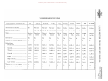
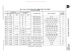
TRANSMISSION MODELS (1 H)
HDS
T-87-D
H-41-B
T-98
F-51
Warner
Fuller
Fuller
Fuller
Fuller
Fuller
Fuller r:
r
F-51-C
F-52
F-52-C
F-54
F-54-B
Transmission (make) ••••••••
IH
Warner
Manufacturer's model ••••••••
-----
AS-4-T-87D AS-74-T-9 ASA T-98
5-A-330
5-A-33
5-A-430
5-A-43 5-A-620
5-A-62
[T1
Type • . • . . . • . . • . • • • • • • • •
Synchromesh
Synchromesh
Direct
in 4th
Synchromesh
O.D. in
5th
Direct
in 5th
O.D. in
5th
Direct
in 5th
O.D. in
5th
Direct
in 5th
Overdrive • • • • • • • • . • • • • • • •
No
No
No
No
Yes
No
Yes
No
Yes
No
o--l
o:::a
Number of forward speeds •••••
1
1
I
1
1
1
1
1
1
2
--l
Reductions:
First (low) • . • • • • • • • • • • •
Second • • • • • • • • • • • • • • • •
Third • • • . • • • • • • • • • • • • •
Warner
Z
3:
:::a
C
()
3.058-1
3.714-1
6.40-1
6.398-1
6.36-1
7.35-1
6.98-1 8.03-1
7.07-1
8.08-1
A
(f)
1.481-1
1.871-1
3.09-1 3.092-1
3.725-1
4.30-1
3.57-1
4.61-1
3.50-1
4.67-1
1.000-1
1.000-1
1.69-1
1.686-1
1.92-1
2.52-1
1.89-1
2.46-1
1.72-1
2.62-1
[T1
:::a
<
() -----
-----
1.00-1
1.00-1
1.000-1
1.42-1
.................
-----
-----
-----
-----
.823-1
1.000-1
High reverse • • • • • • • • • • • •
-----
-----
----
-----
-----
-----
-----
-----
-----
8.12-1
z
c
Low revers e • • • • • • • • • • • •
3.707-1
4.588-1
7.82-1
7.820-1
6.39-1
7.20-1
6.95-1
8.00-1
7.11-1 4.74-1
r
Number of p. T. O. oppni'1g ••••
None
None
1
1
2
2
2
2
2
2
Lubricant capacity (pints) ••••••
3
6
5
8
12 12
19
19
24
24 Fourth • • • • • • • . • • • . • . • •
Fifth
1.00-1
.825-1
1.41-1
1.00-1
1.000-1
.776-1
1.38-1
1.00-1 [T1
3:
»
»
en
'U
M>-j
0::0
1-<>
~z
oen
>E::':
>-jen
...... en
0 .....
ZO
~enZ
Donated by John & Susan Hansen - For Personal Use Only
'\jCllI-j
$ll '\j::o
aQ
M:>
(1)()Z
N ...... CIl
:::lg:
() ......
:>g;
I-j ......
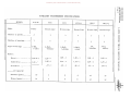
AUXILIARY TRANSMISSION SPECIFICATIONS
HO
Oz
Z
MODEL
2-A-45
Make
Fuller
5531
Brown-Lipe
6231
Brown-Lipe
6231-A
8031-C
CIl
8031-G
r
Brown-Lipe
Brown-Lipe
Brown- Lipe
r
z
[T1
Number of speeds ••••••
....
Number of bearings
Type of bearings
•
0
••••
2
3
3
3
3
3
3:
o
o
-l
7
6
6-Ball,
I-Roller
2-Ball,
4-Roller
7
I-Ball,
6-Roller
7
6
6
I-Ball,
6-Roller
3-Ball,
3-Roller
3-Ball,
3-Roller
::0
-l
::0
C
(')
A
t/)
[T1
Ratios;
::0
<
1.00 to 1
1.00 - 1
1.00 - I
1.00 - 1
1.00 - 1
1.00 - 1
(')
[T1
Underdrive ••••••••
1.30 - I
2.00 - 1
2.14 - 1
1.24 - 1
2.59 - 1
1.29 - 1
3:
Overdrive
--------
.72 - 1
.69 - 1
.86 - 1
.75 - 1
.84 - 1
Di r ec t '" .
II;J
•
0
'"
'ill
'"
......
.....
0
GO
0
•
Lubricant capacity:
Summer (pints) • • •••
10
6
8
8
12
12
Winte r (pints) ••••••
10
6
8
8
12
12
»
z
c
»
r
Donated by John & Susan Hansen - For Personal Use Only
L-UNE MOTOR TRUCK SERVICE MANUAL TRANSMISSION
General
Page I
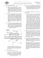
TRANSMISSIONS Driving Downhill
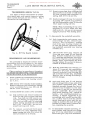
A safety rule to follow by all good drivers is
to use the same or next lower transmission gear
when going downhill as would be used in climbing
the same hill. If necessary, the vehicle speed
can then be easily controlled to the maximum road
speeds for that particular gear by "snubbing
down" with the brakes. This practice will not
only prevent damage to the engine, but will also
effect a saving on the brakes.
CAUTION: Do not coast down hill, even for a very
short distance, with the clutch disengaged. If
the clutch is engaged while the truck is coasting,
the sudden acceleration of the engine's speed will
result in a shock to the gears, an excessive
strain and ultimate failure of the driving parts.
Overdrive
Some transmis sions have an over-drive
spe ed. This gearing is for maintaining in
creased road speed with reduced engine speed.
Overdrive should be used only when conditions
are favorable to high road speeds. Overdrive
should never be used at low road speeds or for
lugging. Usually, for overland hauling, the
minimum road speed for overdrive is 30 m.p.h.
Overload
The transmis sions installed in International
trucks are engineered to the rated capacity
of the trucks. An ample safety factor well
above normal requirements has been provided,
but neither the transmission nor any other part
of the truck will give maximum performance
and long wear if continued to load it beyond its
rated capacity.
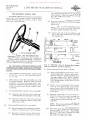
Shifting
Probably one of the most distinguishing
characteristics of a good driver is his ability
to shift gears from a high to a lower trans
mis sion speed.
A knowledge of the maximum obtainable road
speeds in the various gears is helpful in deter
mining the maximum road speed at which a shift
bom a high to a lower gear can be made.
For example, in shifting fourth speed to
third speed. the maximum road speed at which
this change can be made is at approximately
PRINTED IN UNITED STAT~$
or
AMERICA
thirty-three miles per hour since that is the
maximum available road speed for this truck
in third gear.
Gear changes from a higher to lower gear
speeds should be made as follows:
1. Ease off on accelerator and disengage clutch.
2. Move gear shift lever to neutral position and
engage clutch. At same time, accelerate
engine to governed speed.
3. Disengage clutch, ease off on accelerator,
and move gear shift lever to next lower
transmission gear position.
4. Engage clutch and depress accelerator
sufficiently to pick up load.
The above procedure, known as "double
clutching," is necessary to bring about an equal
ization or synchronization of engine speed and
transmission gear speed, and thereby prevent
clashing of gears.
When the truck is equipped with a governor
the maximum engine speed is controlled. If,
however, it is desired to shift at lower road
speeds than those shown, the shifts should be
made at correspondingly lower engine speeds.
Since the governor does not operate at the lower
engine speeds, determination of the proper lower
engine speed at which to shift is a matter of
judgment that comes with practice.
When the operator becomes accustomed to
the sound of the engine at various engine speeds
and has become experienced at "double-clutching"
he should be able to shift from a high to a lower
gear very rapidly--and without clashing the
gears. CAUTION: When shifting, avoid injury
to the gear teeth by making it a practice to shift
gears with as little clashing as possible.
Starting
When starting a new unit or one which has
been exposed to cold weather, allow sufficient
time for the lubricant to circulate and coat all
contacting surfaces. Do not stay in anyone
gear for any length of time. The metal-to-metal
contact between some of the working parts, due
to insufficient lubrication, will result in damage
which may not appear immediately but will
eventually develop into serious trouble.
Donated by John & Susan Hansen - For Personal Use Only
Donated by John & Susan Hansen - For Personal Use Only
L-UNE MOTOR TRUCK· SERVICE MANUAL
TRANSMISSION
Section A
Page 1
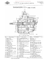
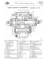
TRANSMISSION (HDS) 49 48
47
46
39
38
36
37
35 34 33
A-21744
Fi g. I - (H DS)
No.
Description
1.
2.
3.
4.
5.
6.
7.
S.
9.
10.
11.
12.
13.
14.
15.
16.
17.
IS.
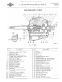
Main drive gear bearing retainer.
Retainer gasket.
Main drive gear.
Mainshaft pilot bearing spacer.
Sliding clutch synchronizer ring.
Mainshaft clutch sleeve.
Clutch poppet ball.
Selector lever assembly.
Clutch poppet spring.
Second speed gear lock ring.
Second speed gear.
Transmission cover.
Shift lever assembly.
Shift lever setscrew.
Mainshaft adapter.
Second speed gear,lock ring.
Mainshaft. Mainshaft sliding gear (low and reverse) .
19" Transmission cover gasket.
20. Rear bearing retainer gasket.
21. Mainshaft rear bearing.
22 .• Speedometer drive gear.
23. I Mainshaft rear bearing retainer.
24. Oil seal.
PRINTEO IN UNITE!:) STATES OF AMtR1CA
NO'
I
i
I
Description 25. Flange.
26. Lockwasher.
27. Nut.
28. Oil slinger.
29. Speedometer gear spacer.
30. C ounte r shaft.
31. Countershaft thrust washer (bronze).
32. Countershaft thrust washer {steel}.
33. Countershaft roller bearing.
34. Transmission case.
35. Countershaft gear cluster.
36. Countershaft bearing spacer.
37. Drain plug. 3S. Countershaft roller bearing. 39. Countershaft thrust washer.
40. Second speed gear thrust washer.
41. Clutch sleeve (second and high).
42. Clutch hub (second and high). 43 •. Main drive gear ball bearing. 44. Bearing lock ring.
45. Mainshaft pilot bearing.
46. i Idler shaft snap ring.
47. Reverse idler shaft.
4S. Reverse idler gear.
49. Reverse idler gear bushing.
Donated by John & Susan Hansen - For Personal Use Only
TRANSMISSION
Section A
Page 2
L-UNE MOTOR TRUCK SERVICE MANUAL
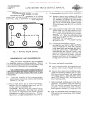
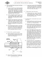
Use shift bar to tap out bar thiInbles
(dust plugs). With the reInoval of shift
bar, the shift fork is lifted out through
top of case.
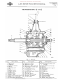
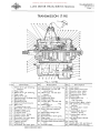
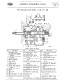
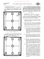
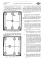
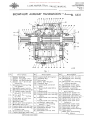
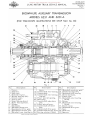
TRANSMISSION (MODEL HDS)
The Model HDS transInission is of synchro
Inesh type with reInote control having three
speeds forward and one reverse. Fig. 2 illus
trates the shift diagraIn.
(c) ReInove interlock plunger retainer
capscrew to release interlock plunger
froIn case.
CAUTION: In reasseInbling trans
Inission, be sure to insert interlock
plunger, poppet springs and balls.
~
I
I
(d) ReInove low and reverse shift bar and
fork, in the saIne Inanner as described
in paragraph (b).
I
I
"''1
Fig. 2 - Shifting Diagram (HDS)
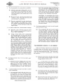
DISASSEMBLING AND REASSEMBLING
With a few Ininor exceptions, the asseInbly is
siInply the reverse of disasseInbling. Therefore
the following disasseInbly instructions will also
serve as reference for asseInbling.
Fig. 1 illustrates construction details of this
transInission and figure nUInbers in parentheses
throughout this section will refer to this illu
stration.
1. Clean outside of transInission, particularly
around the control and bearing covers
(1, 12,23).
2. Shift selector lever (8) and shift lever (13)
to neutral position. ReInove cotter pin and
breather cap froIn hold-down bolt. Re
Inove four capscrews and lockwashers frOIn
control cover (12) and lift off control cover
asseInbly.
3. To disasseInble the control cover asseInbly:
(a) ReInove outer selector lever setscrew
releasing both outer and inner levers (8).
(b) ReInove shift lever setscrew (14) and
this will release the shaft, spring and
shift lever (13).
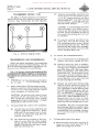
4. DisasseInbling shift forks and shafts:
(a) ReInove poppet ball and spring retainer
plugs releasing balls and springs.
(b) ReInove setscrews frOIn shift forks
and slide shift bar toward rear of case.
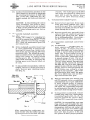
Fig. 3 - Sectional View of Shifting Bars,Poppet
Springs and Balls and Shifting Forks.
5, ReInoving Inain drive gear asseInbly:
(a) Lock transInission and reInove COIn
panion flange (25). ReInove caps crews
three in nUInber - froIn Inainshaft rear
bearing retainer (23). Lift off retainer
and gasket (20) revealing oil deflector
(28), speedoIneter drive gear (22) and
spacer (29).
(b) Drive out countershait (30) toward
rear of case perInitting countershaft
gear cluster (35) to drop down in case,
allowing clearance for reInoval of Inain
drive gear.
(c) ReInove caps crews - four in nUInber
froIn the Ina in drive gear bearing re
tainer (1). ReInove retainer (1) re
vealing Inain bearing (43) and retaining
ring (44).
NOTE: When reasseInbling, see that oil
drain in r<::!tainer (1) is located at bottoIn.
(d) Main drive gear (3) and bearing (43) can
now be reInoved froIn case (34) by driv
ing toward front of case. CAUTION:
Exercise care not to daInage bearing
(43) when driving froIn case.
Donated by John & Susan Hansen - For Personal Use Only
L-UNE MOTOR TRUCK SERVICE MANUAL
6. RerrlOval of mainshaft assembly:
(a) With companion flange (25) and main
shaft bearing retainer (23) removed,
slip off oil deflector (28) speedometer
drive gear (22) and spacer (29) from
mainshaft assembly.
(b) Remove mainshaft rear bearing (21).
CA UTION: Exercise care in driving
off bearing to prevent its being damaged.
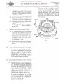
(b) To reassemble, insert clutch partially
in sleeve and install springs and balls.
Then insert cotter pins (1/8 x 2 ") hav
ing the ends spread slightly as shown in
Fig. 4. The cotter pins, when
between the splines, force the balls
into the clutch and after clutch is
pressed into sleeve, cotter pins can
be removed.
(c) Mainshaft assembly can then be lifted
out through top of case.
NOTE: Main drive gear assembly (3)
must be removed first as outlined in
paragraph 5.
7. Removal of countershaft cluster gear:
(a) As countershaft (30) has already been
removed for disassembly of main drive
gear (3), the counter shaft gear cluster
(35) is merely lifted out through top of
case. Be sure to remove the bronze
washer (39) at front and bronze washer
(31) and steel thrust washer (32) at
rear in bottom of case.
Fi g. 4
(b)
Countershaft bearings (38) and spacer
(36) can also be removed from gear
cluster.
8. Removal of reverse idler gear and shaft:
(a) Reverse idler shaft (47) can now be
removed by dr~ving shaft toward rear
of case and this will permit lifting
idler gear (48) out through top of case.
NOTE: When reassembling, be sure to
position shaft so that recess will take
rear bearing retainer properly.
9. Disassemblyofmainshaft clutch assembly:
(a) Mainshaft clutch and sleeve are held
together by poppet springs (9) and balls
(7). Mainshaft clutch can be removed
from sleeve by supporting outer diameter
of sleeve and pressing on clutch. Use
care when disassembling as poppet
balls are under spring tension and may
fly out when sleeve is removed. It is
suggested that a cloth be wrapped around
the assembly to guard against this.
A special tool, SE-920, is available
which if used, will facilitate disassembly
and reassembly. If you do not have this
tool on hand, follow instructions out
lined in paragraph (b).
"~INT£D
IN UNJTED $TATES OF' AMERICA
TRANSMISSION
Section A
Page 3
Donated by John & Susan Hansen - For Personal Use Only
Donated by John & Susan Hansen - For Personal Use Only
L-UNE MOTOR TRUCK SERVICE MANUAL
TRANSMISSION
Section B
Page 1
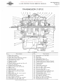
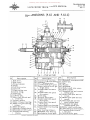
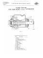
TRANSMISSION {T-87-D} Fig. I - (T-87-D)
No.
1.
2.
3.
4.
5.
6.
7.
B.
9.
10.
11.
12.
13.
14.
15.
16.
17.
lB.
19.
20.
21.
22.
Description
Main drive gear.
Bearing snap rings.
Main drive gear bearing retainer.
Synchronizer blocking ring.
Transmission cover.
Expansion plug.
Shifting plate.
Clutch sleeve (second and direct).
Interlock plunger.
Poppet ball and spring.
Shift fork (second and third).
Shift lever.
Shifting shaft.
Shift fork (low andl"everse).
Mainshaft second speed gear.
Shift rail.
Mainshaft low and reverse, gear.
Expansion plug.
Transmission cover gasket.
Oil retainer washer.
Mainshaft rear bearing retainer.
Mainshaft
'ing snap ring.
PRINTEO IN U!'4fT£D STATES OF AM£RICA
No.
23.
24.
25.
26.
27.
2B.
29.
30.
31.
32.
33.
34.
35.
36.
37.
3B.
39.
40.
41.
42.
43.
44.
Description
Mainshaft rear bearing.
Oil seal.
Mainshaft.
Mainshaft flange nut.
Speedometer drive gear.
Counter shaft thrust washer (inner).
Countershaft thrust washer (outer).
Counter shaft.
Lock plate.
Lock plate capscrew.
Reverse idler shaft.
Reverse idler gear bushing.
Reverse idler gear.
Countershaft gear cluster.
Countershaft thrust washer (front).
Countershaft roller bearing.
Transmission case.
Countershaft bearing spacer.
Oil retainer washer.
Main drive gear bearing.
Clutch hub (second and direct).
Mainshaft pilot bearing.
Donated by John & Susan Hansen - For Personal Use Only
TRANSMISSION
Section B Page 2
L-UNE MOTOR TRUCK SERVICE MANUAL
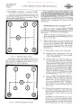
TRANSMISSIONS (MODEL T-87-D)
The Model T-87-D transmission is of syn
chro-mesh type, with remote controls, having
three speeds forward and one reverse. Fig. 2
illustrates the shift diagram.
~
(c) Remove snap rings from shifting shaft
(13) located on each side of shift lever
(12) thus releasing shaft assembly (13),
spring, shift lever (12) and key.
(d) Interlock plunger (9) may be removed
by pulling 3/8" tapered plug located on
left side transmission cover (5) directly
below poppet spring and ball.
NOTE: When reassembling the top cover
assembly (5) to case, make sure that
shift forks (11, 14) are not sprung and
engaged properly with sliding gears.
I
I
4. To disassemble the mainshaft assembly,
I
I
"'"
Fig. 2 - Shifting Diagram (T-87-D)
DISASSEMB LING AND REASSEMB LING
The assembly is simply the reverse of dis
assembling with the exception of a few minor
details. Therefore the following disassembly
instructions will also serve as reference for
assembling.
Figure numbers in parantheses throughout
this section will refer to Fi . 1 which illustrates
construction details 0 this transmission.
1. Clean outside of transmission especially
around the control and bearing covers
(3,' 5, 21).
2. Shift selector lever (12) into neutral position.
Remove capscrews and lockwashers holding
cover assembly (5) to case (39) and lift
off the cover assembly.
3. To disassemble the control cover assembly:
(a) Clip lockwire and remove locks crew
from low and reverse speed shift fork
(14). Tap shift rail (16) toward rear
of cover driving out expansion plug
(18). Pull out shift rail (16) releasing
poppet spring and ball (10) and shift
fork (14). CAUTION: Do not lose
poppet springs and balls.
(b) To remove second and third speed
shift fork (11), rail, expansion plug,
poppet spring and balls (1 0), follow the
same procedure as in step (a).
(a) Lock transmission and remove com
panion flange nut (26). Remove cap
screws - four in number - holding
main drive gear bearing retainer (3)
to case (39) and five capscrews hold
ing mainshaft assembly rear bearing
retainer (21).
(b) Lift off main drive gear retainer (3)
revealing snap rings (2) and bearing
(42). Remove mains haft rear retainer
(21) re:vealing speedometer drive gear
(27) snap ring (22) and bearing (23).
NOTE: When reassembling the front
bearing re.tainer (3) see that oil drain in
retainer is located at bottom.
(c) With the mains haft rear bearing re
tainer (21) removed, slip speedometer
drive gear (27) from mainshaft (25).
Remove mainshaft rear bearing (23)
and oil retainer washer (20). CAUTION:
Exercise care in driving off bearing to
prevent damage.
(d) Pull main drive gear (1) and bearing
(42) out through front of case until drive
gear contacts countershaft gear. Slide
rnainshaft assembly through rear bore of
case as far as necessary to clear main
drive gear (1) and lift out through top
of case. CAUTION: Be sure to catch
pilot needle bearings (14) - sixteen in
number - when removing mainshaft as
sembly. A helpful suggestion in re
assembling pilot needle bearing (44),
use a rubber band to hold the sixteen
needle bearings in place until the as
sembly is started in the main drive gear
and then the rubber band is removed be
fore completing the assembly.
(e) To disassemble rnainshaft assembly, re
more retainer snap ring and use sliding
gear (17) to tap synchronizer assembly
and bushed gear (15) from rnainshaft.
Donated by John & Susan Hansen - For Personal Use Only
L-UNE MOTOR TRUCK SERVICE MANUAL
5. To disassemble main drive gear:
(a) Remove snap ring (2) holding bearing
(42) on main drive gear (1). Push the
drive gear and bearing assembly back
into case until outside snap ring seats
snuggly against case. USLrlg a soft ham
mer, tap the mains haft gently toward
inside of case until bearing is freed
and the mainshaft can then be lifted
out through top of case. CAUTION: Do
not damage bearing during this operation.
6. To disassemble countershaft assembly:
(a) Remove capscrew (32) and lock plate
(31) releasing countershaft (30) and
reverse idler shaft (33). Drive counter
shaft (30) out through rear of case using
a brass drift. With the countershaft
removed, the gear cluster (36) can be
lifted out through top of case. Be sure
to pick up the bronze thrust washer
(37) at front and bronze washer (28)
and steel washer (29) at rear in bottom
of case.
(b)
Countershaft bearings (38) and spacer
(40) can also be removed from gear
cluster.
7. Removal of reverse idler gear and shaft:
(a)
Reverse idler shaft (33) can be re
PRINTED IN UNITED STATES
O~
AMERICA
TRANSMISSION
Section B
Page 3
moved by driving out through rear of
case. May also be removed by placing
a pinch bar in lock plate slot and pulling
out shaft. With the idler shaft (33)
removed, the idler gear (35) can be
lifted out of case. NOTE: When re
assembling, be sure to position properly
slots in countershaft (30) and idler
shaft (33) to take lock plate (31).
8. To disassemble mains haft clutch assembly:
(a) The mainshaft clutch hub and sleeve
are held together by two retaining
springs located on each side of clutch
hub. The clutch sleeve (8) can be re
moved from clutch hub (43) by removing
the retaining springs and supporting the
outside diameter of sleeve (8) and
pressing on hub (43). Use care when dis
assembling not to lose the three shifting
plates (7). The blocker rings (4) are
supported by the main drive gear hub and
second speed gear hub and are dis
ass e m bled with the r em oval of the
mainshaft assembly.
CAUTION: In reassembling the clutch,
be sure to place end of each retaining
spring in the same shifting plate with
the loose ends located in same position
on both sides to equalize the tension on
all three shilting plates (7). Also index
etched marking on hub and sleeve.
Donated by John & Susan Hansen - For Personal Use Only
Donated by John & Susan Hansen - For Personal Use Only
L-LINE MOTOR TRUCK SERVICE MANUAL
TRANSMISSION
Section C
Page 1
TRANSMISSION (H-41-B) 33
32
~--31
Fig. I - (H-ltl- B)
No.
1.
2,
3.
4.
5.
6.
7.
8.
9.
10.
11.
12.
13.
14.
Description
Shift lever.
Retainer.
Retainer washer.
Spring.
Fulcrum ball.
Pin.
Contrpl cover.
Poppet spring.
Poppet balL
Interlock pin.
Shifter shaft.
Shift fork prd and direct}.
Shift fork 1st and 2nd}.
M. drive gear brg. retainer.
No.
15.
16.
17.
18.
19.
20.
Zl.
22.
23.
24.
25.
Description
Main drive gear.
Main drive gear.
Main drive gear bearing.
Mainshaft gear (3rd and
direct).
Countershaft thrust
washer.
Countershaft gear cluster.
Drain plug.
Bearing spacer.
Countershaft bearing.
Reverse idle gear.
C ounte r shaft.
P~INTED IN UNITED STATES OF AME~LCA
r;7o.
Description
26. Mainshaft gear (low and
second).
27. Mainshaft rear bearing.
28. Spacer.
29. Speedometer drive gear.
30. Mainshaft.
3l. Washer.
32. Cotter pin.
33. Nut.
34. Grease seal.
35. Rear bearing retainer.
36. Grease slinger.
37. Expansion plug.
38. Shifter fork lock screw.
Donated by John & Susan Hansen - For Personal Use Only
TRANSMISSION
Section C
Page Z
L·LlNE MOTOR TRUCK SERVICE MANUAL
TRANSMISSIONS (MODEL H-41B)
3. To disassemble the control cover assembly:
(a) Remove control lever retainer (Z) from
The Model H-41-B transmission is of sliding
gear type, having four speeds forward and one
reverse. Fig. Z illustrates the shift diagram.
cp
q:>
~- -'N'- -1- -
I ~
cD
top of cover (7). Lift out control lever
(1), retainer (Z). washer (3). and spring
(4) and fulcrum ball (5). Fulcrum ball
(5) can be removed from control lever
(1) by driving out pin (6) with a suitable
punch.
I
cD
(b) Clip lockwire from first and second
- -
-,,
®
Fig. 2- Shifting Diagram (H-Itl-B)
DISASSEMB LING AND REASSEMB LING
With a few minor exceptions, the assembling
is simply the reverse of disassembling. There
fore the following disassembly instructions will
also serve as reference for assembling.
Fig. Z illustratys construction details of
this transmission and figure numbers in paren
theses throughout this section will refer to this
illustr ation.
1. Clean the outside of the transmission,
particularly around the control and bearing
covers (7, 14, 35).
Z. Place shift lever (1) in neutral position.
Remove the six holding caps crews and lift
off the control assembly (7).
CAUTION: Do not force the control cover
off the transmission. Forcing may spring
the yokes of alignment and caus e partial
engagement or gear interference. If bind
ing occurs, a slight manipulation will free it.
speed shift fork (38) and remove lock
screw (38). Drive shift rail (11) to
ward rear of cover driving out expan
sion plug (37). With the expansion plug
removed, pull shift rail (11) out and lift
shift fork (13) out of cover.
CAUTION: Do not lose poppet spring
(8) and ball (9).
(c) Continue disassembly operation re
moving third and direct shift fork (lZ),
reverse shift block, stop pin, spring,
rails, poppet balls and springs and inter
lock pins and stops. CAUTION: In
reassembling the control cover, care
should be exercised to see that all
parts are replaced in their correct
positions and none of the small inter
locking parts are lost or omitted.
4. To remove mains haft assembly:
(a) Lock transmission by engaging two
speeds and remove flange nut (3Z).
(b) Remove five capscrews holding main
shaft rear bearing retainer (35) to case.
Lift bearing retainer off rnainshaft
revealing gasket, speedometer drive
gear (Z9), spacer (Z8), and mainshaft
rear bearing (Z7).
(c) Hold mainshaft sliding gears (18, Z6) in
position. Mainshaft (30) and bearing
(Z7) can now be removed through rear
of case, If necessary, use a brass
drift against washer (3l) and nut (32).
(d) Lift out mainshaft third and direct gear
(18) and low and second gear (26) through
top of case.
Donated by John & Susan Hansen - For Personal Use Only
L-UNE MOTOR TRUCK SERVICE MANUAL
5, To disassemble the mainshait:
(a) Remove nut (32), companion flange,
then remove rear bearing retainer
(35), speedometer drive gear (29),
spacer (28), and bearing (27).
6. Remove main drive gear:
(a) Remove four capscrews holding main
drive gear bearing retainer (14) to case.
(b) Remove retainer (14) revealing gasket
and bearing (17). NOTE: When re
assembling, be sure to locate oil drain
at bottom.
(c) Main drive gear (15) and bearing (17)
can now be removed from front of case.
If necessary, use babbit or rawhide
hammer to tap main drive gear (15).
7. Removing the countershaft assembly:
(a) Remove countershaft and reverse idler
shaft lock screw and plate. Drive out
countershaft (25) toward rear of case,
using a brass drift.
PRINT£O IN UNITED STATI[S OF AMERICA
TRANSMISSION
Section C
Page 3
(b) Remove cotter pin from reverse idler
gear shifter fork shaft. Drive shaft
toward rear of case with a brass drift
and remove idler shifter fork.
(c) Lift countershaft gear cluster (20) with
bearings (23) and spacer (22), through
top opening of case. Tilt gear cluster
slightly through rear bore in case to
facilitate removal.
(d) Remove roller bearings (23) and spacer
(22) from cluster (20). Be sure to
pick up countershaft thrust washers,
one each end, from bottom of case.
8. Removing the reverse idler gear and shaft
assembly:
(a) Insert screwdriver or pinch bar in'lock
plate groove and pry out shaft. Re
verse idler gear can then be lifted out
through top of case. NOTE: When
reassembling, be sure to position slot
in shaft properly to take lock plate.
9. When reassembling the top cover assembly,
make sure that the'shifter forks are not
sprung, and engaged properly with sliding
gears.
Donated by John & Susan Hansen - For Personal Use Only
Donated by John & Susan Hansen - For Personal Use Only
L-LINE MOTOR TRUCK SERVICE MANUAL
TRANSMISSION
Section D
Page I
TRANSMISSION (T-98) Fig. I - (T-98)
No.
Description
l. ~ain drive gear bearing
retainer.
2. Snap ring. 3. ~ain drive gear bearing.
4. Snap ring. 5. ~ain drive gear.
6. Synchronizer blocking ring.
7. Shifting plate.
8. Expansion plug.
9. Sleeve (3rd and dir~ct).
10. Shift rail. 11. Transmission cover.
12. Shift fork, (3rd and direct).
13. Control lever. 14. Control housing cap.
15. Fulcrum ball. 16. Control lever spring.
17. Control lever ball.
18. ~ainshaft 3rd speed gear.
19. Interlock plunger.
20. Poppet spring. 21. Poppet ball. 22. ~ainshaft 2nd speed gear.
Description
No.
23. Synchronizer blocking ring.
24. ~ainshaft 1st and 2nd
speed gear.
25. Shift fork, 1st and 2nd
speed.
26. Poppet ball. 27. Expansion plug.
28. Poppet spring. 29. Clutch hub, 1st and 2nd
speed. 30. ~ainshaft rear bearing
retainer. 31. ~ainshaft rear bearing.
32. Rear bearing retainer
seal. 33. ~ainshaft flange nut.
34. ~ainshaft. 35. Speedometer drive gear.
36. Snap ring. 37. C ounter shaft roller bearing.
38. Countershaft thrustwasher.
rear,
39. Counter shaft. 40.
41.
42.
43.
44.
45.
46.
No.
PAINTED IN UNITEO STATES OF AMERICA
47.
48.
49.
50.
51,
52.
53.
54.
55.
56.
Description
Lock plate. Lock plate capscrew. Reverse idler shaft.
Reverse idler gear.
Transmission case.
Drain plug.
Counter shaft bearing
spacer.
P. T .0. opening.
Countershaft gear cluster.
2nd speed gear bearing
spacer.
2nd speed gear roller
bearing.
Countershaft thrust
washer, front.
Countershaft roller
bearing.
2nd speed gear thrust
washer.
Snap ring.
Clutch hub, 3rd and direct.
~ainshaft pilot bearing.
Donated by John & Susan Hansen - For Personal Use Only
TRANSMISSION
Section D
Page 2
L-UNE MOTOR TRUCK SERVICE MANUAL
TRANSMISSION (MODEL T-98)
The Model T-98 transmission is of synchro
mesh type having four speeds forward and one
reverse. Fig. 2 illustrates the shift diagram.
CD
I
I
CD
I
I
I
I
•
t-----
I
I
I
®N -----1·------------..
I
I
I
I
I
I
I
I
I
CD
CD
CAUTION: In reassembling the control
cover assembly, care shbuld be exer
cised to see that all parts are replaced
in their correct positions and none of
the small interlocking parts are lost
or omitted.
(d) To remove control lever (13) from
cover (11). turn off the housing cap
(14) releasing retainer washer, spring
(16) and fulcru'm ball (15). With the
fulcrum ball and control lever assembly
removed, the control lever pivot pin
can be removed from cover.
I
I
I
(c) Continue disassembly operation in the
same manner as described in para
graph (a), removing third and direct
speed shift fork (12) and first and
second speed shift fork (25), rails, ex
pans ion plugs, poppet springs, balls
and interlock plunger.
A-22937
Fig. 2 - Shifting Diagram (T-98)
4. To remove the mains haft assembly:
DISASSEMBLING AND REASSEMBLING
With a few minor exceptions, the assembling
is simply the reverse of disassembling. There
fore the following disassembly instructions will
also serve as reference for assembling.
Fig. 1 illustrates construction details of this
transmission and figure numbers in parentheses
throughout this section will refer to this illu
stration.
1. Clean outside of transmission particularly
around the control and bearing covers
(1,11,30).
2. Place control lever (13) into neutral position.
Remove caps crews and lockwashers holding
cover (11) to case (44) and lift control
cover assembly off transmission.
CAUTION: Do not force the control cover
as sembly off the transmission. Forcing
may spring the yokes and cause partial
engagement or gear interference. A slight
manipulation will free the cover.
3. To disassemble the control cover assembly:
(a) Cut lock wire on reverse shift block and
remove shift block lockscrew. Drive
shift rail (10) out toward rear of cover
driving out expansion plug (27) and
remove shift block.
(b) Pull tapered plug located on left out
side of cover directly below poppet
spring and ball and remove interlock
plunger (19) and third and direct speed
shift rail interlock pin.
(a) Lock transmission by engaging two
speeds and remove flange nut (33).
(b) Remove capscrews, five in number,
and lift off mainshaft r ear bearing
retainer (30) revealing speedometer
gear (35), bearing (31), and snap rings.
Slide speedometer gear (35) off of
mains haft (34). Disassemble main
drive gear bearing retainer (1) by
removing capscrews and lockwashers,
revealing main drive gear bearing
(3) and snap rings (2) and (4).
(c) Remove main drive gear bearing snap
ring (2) and pull main drive gear (5)
and bearing (3) out through front of
case sufficiently to expose bearing snap
ring (4). Apply bearing puller and re
move bearing (3) from main drive gear
(5). Tap mainshaft assembly toward
rear of case and pull mainshaft rear
bearing (31). Push mainshaft assembly
through rear bore in case to clear
main drive gear (5) and tilt front end
upward and lift out through top of case.
CAUTION: Be sure to catch pilot
needle bearing, sixteen in number, when
removing mainshaft assembly. When
reassembling front bearing retainer
(1). be sure to locate oil drain hole
at bottom.
5. To disassemble main drive gear:
(a) With the main drive gear bearing (3)
removed fr om dr ive gear (5), it is
lifted out through top of case.
Donated by John & Susan Hansen - For Personal Use Only
L-L1NE MOTOR TRUCK SERV1CE MANUAL
6.
To disassemble the mainshaft assembly:
(a) Remove snap ring holding third and di
rect speed clutch assembly and main
shaft third speed gear (18) and slide
clutch assembly and bushed gear from
mainshaft.
(b) Remove first and second speed hub
retainer snap ring (36) and slide off
synchronizer assembly.
(c) Remove mains haft second speed gear
snap ring (54) releasing thrust washer
(53) needle bearing (50), thirty-four
in number, second speed gear (22) and
spacer (49).
7. To disas semble the countershaft assembly:
(a) Remove caps crew (41) and lock plate
(40) locking countershaft (39) and re
verse idler shaft (42).
(b) Using a brass drift, drive countershaft
out through rear of case and lift the
gear cluster (48) out through top of case.
NOTE: The countershaft gear cluster
turns on four sets of roller bearings
(37, 52) which are loose in the bor e of
the countershaft g ear. There are
twenty-two rollers in each bearing
set, totaling eighty-eight bearings,
separated by spacer washers and spacer
(46). These rollers will probably inter
mingle with the main drive gear pilot
bearing rollers (56) in bottom of case
when the countershaft gear is removed.
Countershaft rollers (37, 52) are
slightly smaller than pilot bearing
rollers (56). Be sure to pick up front
thrust washer (51). rear thrust washer
(38) and spacing washer from bottom
of case.
8. To disassemble the reverse idler gear
assembly:
(a) Remove reverse shifting arm and drive
reverse idler shaft (42) out through
rear of case and lift idler gear (43) out
through top of case. NOTE: When
reassembling, be sure to position slot
in shaft properly to take lock plate.
9. To disassemble the third and direct speed
clutch assembly:
(a) The rnainshaft clutch hub and sleeve are
held together by two retaining springs
located on each side of clutch hub.
The clutch sleeve can be removed from
clutch hub by removing the retaining
springs and supporting the outside
diameter of sleeve and pressing on
PRINTEO IN UNfT£O STATES OF" AMERICA
TRANSMISSION
Section D
Page 3
hub. Use care when disassembling not
to loose the three shifting plates (7).
The blocker
are supported by the
main drive gear hub and third ,speed
gear hub and are disassembled with the
removal of the mains haft assembly.
CAUTION: In reassembling the clutch
assembly, be sure to place end of each
retaining spring in the same shifting
plate (7) with the loose ends located
in same position on both sides to equalize
the tension on all three shifting plates
(7). and also index etched marking on
hub and sleeve.
10. To disassemble first and second speed
synchronizer unit:
(a) The mains haft first and second speed
clutch hub (29) and sleeve gear (24)
are held together by poppet springs (28)
and balls (26). The clutch hub (29)
can be removed from sleeve (24) by
supporting the outside diameter and
pressing on the hub. Use care when
disassembling as poppet springs and
balls are under spring tension and may
fly out when sleeve is removed. It is
suggested that a cloth be wrapped around
the assembly to guard against this.
TRANSMISSION REMOVAL (L-160 SERIES)
When it becomes necessary to remove the
transmission on the above series trucks, it
is necessary to disconnect and move to one
side the front propeller shaft. This will per
mit removal of the transmission. Proceed
as follows.
(a) Remove the bolts from the front end
of the front propeller shaft at the joint
flange (Spicer joints used.)
(b) Remove the brake drum retainer bolts
and slide the brake drum out of the
brake band onto the propeller shaft.
(This will provide maximum clear
ance for the end of the propeller shaft
to permit its being moved to one side.)
(c) Carefully pry the shaft end towards the
rear and over the transmission main
shaft flange and nut to permit the shaft
to clear the flange.
(d) Securely wire the shaft to one side to
keep it out of the way while proceed
ing with transmission removal.
Donated by John & Susan Hansen - For Personal Use Only
Donated by John & Susan Hansen - For Personal Use Only
TRANSMISSION
Section E
Page 1
L-LINE MOTOR TRUCK SERVICE MANUAL
TRANSMISSIONS (F-51 AND F-51-C) Fig. I - (F- 51 an d F- 5J- C)
No.
1
Description
1. Main drive gear.
2, Drive gear bearing nut.
3. Front bearing retainer
capscrew.
4. Main drive gear bearing
retainer.
5. Retainer gasket.
6. Shift rail thimble.
7. Interlock pin. 8. Poppet ball. 9. Poppet spring.
10. Control cover.
11. Shifter fork lockscrew.
12. Shifter fork, 4th & 5th
speed.
13. Shifterforklockwire.
14. Spring. 15. Retainer. 16. Dust cover. 17. Shift lever, and ball. 19. Mainshaft sleeve, 5th gear.
20. Mainshaft 5th gear.
21. Mainshaft3rdspeedwasher.
22. 3rd speed constant mesh
gear.
No.
Description
23. Reverse idler roller
bearing.
24. Reverse idler gear.
25. Reverse idler shaft.
26. Shifter fork, 2nd & 3rd
speed.
27. Mainshaft 2nd & 3rd speed
gear. 28. Shifter fork (low & reverse}.
29. Mainshaft low & reverse
gear. 30. Mainshaft. 31. Control cover gasket.
32. Rear bearing cover gasket.
33. Speedometer drive gear
key. 34. Speedometer drive gear.
35. Rear bearing retainer.
36. Mainshaft rear bearing
grease seal.
37. Flange nut. 38. Flange lockwasher.
39. Flange. 40. Mainshaft rear bearing.
41. Countershaft rear bearing.
PRINTED IN UNITEO STATES Of' AMERICA
No.
Description
42. Countershaft rear bearing
lock nut.
43. Drain plug.
44. Countershaft gear, 1st, 2nd
& reverse. 45. Countershaft 3rd speed gear.
46. Counter shaft 5th speed
gear.
47. Mainshaft 5th gear washer.
48. Mainshaft 5th speed gear
key.
49. Countershaft drive gear.
50. Spacer.
5!. Key.
52. Countershaft snap ring.
53. Countershaft front bearing
washer.
54. Countershaft front bearing.
55. Countershaft front bearing
retainer.
56. Expansion plug snap ring.
57. Mainshaft sliding clutch.
58. Main drive gear bearing.
59. Mainshaft pilot bearing.
Donated by John & Susan Hansen - For Personal Use Only
TRANSMISSION
Section E
Page 2
L-UNE MOTOR TRUCK SERVICE MANUAL
TRANSMISSIONS (MODELS F-51 and F-51C)
The Model F-Sl transmission (S-A-330)
has five speeds forward and one reverse. Fifth
speed is overdrive. Fig. 2 illustrates the shift
diagram.
I
<P
I
I
I
q)
I
I
r----¢-
~
I
I
I
I
-~--.I
I
I
I
I
I
I
I
I
I
® <D
cD A·22886
Fig. 2 - Shifting Diagram (F-5J)
The Model F-Sl-C transmission (5-A-33) is
constructed having five forward speeds and
one reverse speed. Fifth speed is direct.
Fig. 3 illustrates the shift diagram.
<P
I
I
I
I
r--I
I
I
I
®
I
I
I
I
-¢----~
I
I
I
cb
I
<b A·22882
Fig. 3 - Shifting Diagram (F-51-C)
Fig. 1 illustrates construction details of
the F-Sl and F-51-C transmissions and figure
numbers in parentheses throughout this section
will refer to this illustration. Item (20) on
Fig. 1 will be referred to as Mainshaft Fifth
Speed Gear although due to change in diameter
on F-51-C, direct in fifth transmission, it is
used as fourth speed gear.
DISASSEMBLING AND REASSEMBLING
With a few exceptions, the assembling is
simply the reverse of disassembling. There
fore the following disassembly instructions will
also serve as reference for assembling.
1. Clean the outside of the transmission,
particularly around the control and bearing
covers (4, 10. 35).
2. Place shift lever (17) to neutral position.
Remove nine caps crews and lockwashers
from control cover (10) and lift cover
assembly and gasket (31) from top of case.
3. To disassemble the control cover assembly:
(a) Cut lockwire (13) at fourth and fifth speed
shift fork {12} and remove shift fork
lockscrew (11). Drive shift rail out to
ward front of cover driving out shift
rail thimble (6) and remove shift fork
(12). Do not lose poppet ball (8) and
spring (9).
(b) Remove interlock ball and pin retainer
plug located on left outside of cover
directly below the poppet spring and ball
housing, releasing interlock ball and pin
{7}.
(c) Continue disassembly operation re
moving low and reverse and second and
third speed shift forks (26, 28). shift
block, step pin, spring and rails. Do
not lose shift rail poppet balls (8) and
springs (9) or interlock pin (7) and balls.
(d) Remove shift lever ball (18) from shift
lever (17). Remove lever dust cover
(16) and also nut and lockwasher from
control lever pivot pin. Place cover
(10) in a vise, grasp lower end of con
trol lever spring (14) with a large
pliers and twist it from its retaining
lugs. Spring may also be removed by
use of a pinch bar and for dng spring
over the retaining lugs. The shift lever
(17) may now be lowered through the
control cover (10). Control lever pivot
pin can also be removed from cover.
CAUTION: In reassembling the controls,
care should be exercised that all parts
are replaced in their respective
positions.
Donated by John & Susan Hansen - For Personal Use Only
L-UNE MOTOR TRUCK SERVICE MANUAL
4. Disassembling main drive gear and main
shaft assembly:
(a) Lock transmission and disassemble
flange nut (37), washer (38) and flange
(39). Remove six capscrews and lock
washers from mainshaft rear bearing
retainer (35). Lift retainer and gasket
(32) from case. Slide speedometer drive gear (34) from mainshait (30) and remove speedometer gear drive key (33).
(b) Drive mains haft assembly toward rear
of cas e sufficiently to expose rear
bearing (40) snap ring. Install suitable puller and pull bearing (40) from main shaft (30). (c) Remove six capscrews (3) and lock
washers from main drive gear bearing retainer (4) and lift off retainer (4) and gasket (5). Remove main drive gear
(1) and bearing (58) and also main
shaft pilot bearing (59) out through front of case. (d) Lift mainshaft (30) and gears out through
top of case, tilting front end upward and
leaving low and reverse speed gear
(29) in case. With the mains haft as
sembly removed, lift out low and re verse speed gear (29) out of case. 5. To disassemble mains haft assembly:
(a) Slide mainshaft second and third speed
gear (27) from mainshaft and also the
mainshaft sliding clutch (57) from op
posite end of mains haft.
TRANSMISSION
Section E
Page 3
speed gear washer (47) on mains haft
to index lugs with splines of shaft and
then remove (Figure 4). Slide main
shaft fifth speed gear (20) sleeve (19)
and washer (21) from shaft.
6. To disassemble main drive gear:
(a) Remove peened over material from slots
in main drive gear and turn off drive
gear bearing nut (2). NOTE: Nut is
left-hand threaded. Press bearing (58)
from main drive gear (1).
7. To disassemble countershaft and reverse
idler gear:
(a) Remove peened over material from slots
and r emove countershaft rear bearing
nut (42) from countershaft (44).
(b) Remove capscrew and lockwasher from
reverse idler shaft lock plate and re
move from slot in idler shaft (25).
Drive idler shaft (25) toward rear of
case and lift idler gear (24) and roller
bearings (23) from case.
(c) Drive countershait assembly (44) toward
rear of case sufficiently to expose rear
bearing (41), attach puller. and remove
rear bearing from countershaft. Lift
countershaft as'sembly through top of
case, lifting front end upward and tilt
ing assembly. Also remove front bear
ing thrust (53). The countershaft front
bearing is disassembled by removing
snap ring (56) from groove and drive
retainer (55) from case. The counter
shaft front bearing (54) may now be
removed from case.
(d) To disassemble the countershaft as
sembly, remove snap ring (52) from
countershaft. Using adapter plates,
press countershaft drive gear (49)
spacer (50) fifth speed gear (46) and
third speed gear (45) from counter
shaft (44) and remove gear keys (51).
CAUTION: In reassembling, NEW snap
rings should be used throughout the unit•
....J
Washer
I
, _•• _
(
.. ..J
A·22941
Fj g. 4
(b) Remove fifth speed gear key (48) from groove in mainshaft (30). Rotate fifth PRINT£D!N UNITED STATES OF ... MERICA
Donated by John & Susan Hansen - For Personal Use Only
Donated by John & Susan Hansen - For Personal Use Only
TRANSMISSION
Section F
Page 1
L-LINE MOTOR TRUCK SERVICE MANUAL
TRANSMISSIONS (F-52 AND F-52-C) 16
23
24
25
26
27
28
29
30
31
8..757
Fig. I - (F-52 and F-52C)
No.
Description
1. Shift lever. 2. Dust cover.
3, Spring retainer.
4. Spring. 5. Shift lever cover.
6. Capscrew. 7. Poppet spring cover.
8. Control cover.
9. Poppet spring. 10. Poppet ball. 11. Interlock pin.
12. Shifter fork {direct and
overdrive).
13. Retainer gasket. 14. Main drive gear bearing.
15. Main drive gear bearing
retainer.
16. Main drive gear.
17. Mainshaft sliding clutch.
18. Mainshaft overdrive gear.
19. Counter shaft bearing
retainer.
No,
20,
21.
22.
23.
24.
25.
26.
27.
28.
29.
30.
31.
32.
33.
34.
35.
Description Countershaft gear key.
Countershaft front bearing.
Transmission case,
Countershaft drive gear.
Power take-off drive gear
(right side).
Countershaft overdrive
gear. Countershaft 3rd speed
drive gear.
Drain plug. Reverse drive gear.
Countershaft 2nd speed
drive gear.
Countershaft low speed
drive gear.
Countershaft rear bearing.
Countershaft rear bearing
lock nut. Rear bearing retainer.
Mainshaft rear bearing.
Speedometer drive gear.
PRINTED IN UNITED STATES OF AMERICA
r;;:.r
36.
37.
38.
39.
40.
41.
42.
43.
44.
45.
46.
47.
48.
49.
50.
51.
Description
Mainshaft rear grease seal.
Cotter pin. Nut. Washer.
Mainshaft.
Shifter shaft rear cove r.
Shifter shafts.
Mainshaft low and reverse
sliding gear.
Shifter fork (low and re
verse).
Shifter fork (2nd and 3rd
speed).
Mainshaft 2nd and 3rd
spe ed sliding gear.
Mainshaft 3rd speed
constant mesh gear.
Shifter shaft lock screw.
Mainshaft gear lock washer.
Constant mesh reverse
idle gear.
Reverse drive gear.
Donated by John & Susan Hansen - For Personal Use Only
TRANSMISSION
Section F
Page 2
L-LINE MOTOR TRUCK SERVICE MANUAL
TRANSMISSIONS (MODELS F-52 and F-52-C)
The Model F-S2 transmission (S-A-430) is
constructed having five forward speeds and one
reverse. Fifth speed is overdrive. Fig. 3
illustrates the shift diagram.
G'
I
I
~
DISASSEMBLING AND REASSEMBLING
I
I
I
I
I
I
I
~---~---~ I
I
I
I
I
I
I
I
I
cD
<P I
I
I
~---®--
(2) 2. Place shift lever (1) to neutral position.
then remove the holding capscrews and
lift off the control cover assembly. CAU
TION: Do not try to force the cover off,
as it rna y spring the shifting yokes and
cause gear interference. A slight manipu
lation will free it.
<P cp I
I
I
-+-~
I
I
I
I
0)
I
I
I
-1
I
I
I
®
A-22883
Fig. 3 - Shifting Diagram ( F-52-C)
Disassemblingthe c ontrol cover assembly:
(a) Remove four capscrews and lift shift
lever cover assembly (S) from control
cover assembly (8).
The Model F-S2-C transmission (S-A-43) is
constructed having five speeds forward and one
reverse. Fifth speed is direct. Fig. 4 illustrates
the shift diagram.
I
1. Clean the outside of transmission, particu
larly around the control and bearing covers
(IS, 8, S, 33).
3.
Fig. 2 - ShiftIng Diagram (F-52)
,
With a few exceptions, the assembly is
simply the reverse of disassembly. There
fore, the following disassembly instructions
will also serve as reference for assembly.
0 ®
A-22SS1
I
I
Fig. 1 illustrates construction details of the
F-S2 and F-S2-C transmis sions and figure
numbers in parentheses throughout this section
will refer to this illustration. Item (18) on Fig.
1 will be referred to as mains haft fifth speed
gear although due to change in diameter on
F-S2-C, direct in fifth transmission, it is used
as fourth speed gear.
(b) Remove shift lever ball from shift
lever (1) and also dust cover (2). Re
move nut and lockwasher from pivot
pin. Place cover in vise, grasp lower
end of control lever spring (4) with
a large pliers and twist it from its
lugs. Spring may also be removed by
use of a pinch bar and forcing spring
over the retaining lugs. With the spring
removed, releasing spring retainer (3),
the lever (1) can be lowered through
shift lever cover (S).
(c) Remove caps crews (6) and poppet
spr ing and ball cover plate (7) re
leasing poppet springs (9) and balls
(10). Cut lockwire at reverse shift
block and remove lockscrew. Drive
shift rail (42) toward rear of cover
driving out shift rail cover (41). Pull
shift rail out releasing reverse shift
block on inside of cover. CAUTION:
Do not lose poppet spring (9) and ball
(10) •
(d) Remove interlock ball retainer 'cap
located on left outside of cover directly
below poppet spring and ball housing,
releasing the interlock ball and pin
(11) •
Donated by John & Susan Hansen - For Personal Use Only
L-LINE MOTOR TRUCK SERViCE MANUAL
(e)
Continue disassembly operation in the
same manner as described in paragraph
(c) removing the balance of shift rails
(42), covers (41), shift forks (12, 44),
poppet springs and balls and interlock
ball.
remove. The bushed gears (18) (47)
and sleeve are removed by using rear
gear (47) to start the sleeve. Also
remove the sleeve key from shaft.
5.
CAUTION: In reassembling the control
cover assembly, care must be exer
cised to see that all parts are replaced
in their correct positions and none of the
small interlocking parts are lost "Or
omitted.
4.
To disassemble main drive gear:
(a)
Remove four capscrews from main
drive gear bearing retainer (IS). The
main drive gear (16). bearing (14)
and lock nut assembly can then be with
drawn through front of case.
(b)
Remove peened over material from
slots in drive gear shaft (16) and turn
off drive gear bearing lock nut. NOTE
Nut is left-hand threaded. Press bear
ing (14) from main drive gear (16)'.
Disassemble mainshaft assembly:
(a)
After locking gears by engaging two
speeds, the countershaft rear bearing
nut (32) is removed from end of counter
shaft. Remove rear bearing retainer
(33). Slide off speedometer gear (35)
and remove key.
(b)
Drive mainshaft assembly toward rear
of case sufficiently to expose rear
bearing (34) snap ring. Install suit
able puller and pull bearing (34) from
mainshaft (40). By tilting the main
shaft assembly front end upward, the
entire unit comes out easily leaving
sliding gears (46, 43) inside case.
After shaft assembly is removed, the
sliding gears may then be lifted out
of case.
(c)
To disassemble the mainshaft, slide the
sliding clutch (17) from front end of
shaft. Remove gear retaining washer
key (Fig. 5).
,
...J
Washer
I'_ _ _ _ .. .-1(
A.2294'
Fi g.
1+
After removing key, rotate gear re
tainer washer until its inside lugs line
up with grooves in the shaft and then
PRINTED IN UNITED S'TATES OF AM£RICA
TRANSMISSION
Section F
Page 3
6.
To disassemble countershaft and reverse
idler gear:
(a)
To disassemble reverse idler gear, re
move capscrew and lock plate from
groove in idler. A simple method of
pulling idler shaft, use a short piece
of pipe, a long bolt having threads the
same size as those tapped in end of
shaft. Using a flat piece of steel with
a hole in the center sufficiently large
to permit passage of bolt. The nut is
turned on the bolt close up to the head.
The bolt is then passed through plate
and pipe in order named and screwed
into idler shaft. The nut is then tightened
against the plate with the result that the
pulling action is exerted against the
shaft with the case acting as a base
through the pipe and plate. After with
drawing reverse idler shaft, the gears
(50,51) are lifted from case and bear-'
ings removed from idler gear.
(b)
With thecountershaft rear bearing lock
nut (32) removed, drive countershaft
assernblytoward rear of case sufficiently
to install suitable puller to remove
rear bearing (31). By tilting the front
end upward, the countershaft assembly
is easily removed through top of case.
Also remove front bearing thrust washer.
(c)
To disassemble countershaft, remove
retaining snap ring from countershaft.
Countershaft gears (23, 24, 25, 26)
should be pressed off, one at a time,
and keys (20) removed from shaft.
CAUTION: In reassembling, new snap
rings should be used throughout the unit.
When reassembling mainshaft assembly,
always replace lock key and washer and
make sure the gears are neither tight
nor 10'ose after they are assembled.
Make sure that all gears in the unit
are replaced in their proper position.
Donated by John & Susan Hansen - For Personal Use Only
Donated by John & Susan Hansen - For Personal Use Only
TRANSMISSION
Section G
Page 1
L-UNE MOTOR TRUCK SERVICE MANUAL
TRANSMISSIONS (F-54 AND F-54-B) Fi g.
No.
1.
2.
3.
4.
5.
6.
7.
B.
9.
10.
11.
12.
13.
14.
15.
16.
17.
lB.
19.
20.
21.
22.
Description
Shift lever.
Dust cover.
Sp ring r etaine r •
Spring.
Shift lever cover.
Capscrew.
Lockwasher.
Control cover.
Interlock pin.
Shifter fork (dir ect and
overdrive) .
Retainer gasket.
Main drive gear bearing.
Main drive gear bearing
retainer.
Main drive gear.
Main drive gear bearing
retaining nut.
Mainshaft front bearing.
Snap ring.
Mainshaft sliding clutch.
Snap ring.
Expansion plug.
Counter shaft front bearing.
Spacer.
No.1
23.
24,
25.
26,
27.
2B.
29.
30,
31.
32.
33.
34.
35.
36.
37.
3B.
39.
40.
41.
- (F-54- and F-54--B)
Description
Transmission case,
Countershaft drive gear.
Key.
Power take-off drive gear.
Mainshaft overdrive gear.
Countershaft overdrive
gear.
Countershaft 3rd speed
drive gear.
Reverse drive gear.
Countershaft 2nd speed
drive gear.
Drain plug.
Mainshaft.
Counter shaft.
Counter shaft low speed
drive gear.
Countershaft rear bearing.
Countershaft rear bearing
lock nut.
Countershaft rear bearing
retainer.
Snap ring.
Snap ring.
Speedometer drive gear.
PRINTED IN iJNITED STATES OF .. MERICA
No.
42,
43,
44.
45.
46.
47.
4B,
49.
50.
51.
52.
53.
54.
55.
56.
57.
5B.
59.
Description
Nut
Cotter pin,
Washer.
Mainshaft rear grease
seal.
Mainshaft rear bearing.
Rear bearing cover and
speedometer housing.
Gasket.
Shifter shaft rear cover.
Shifter shafts.
Mainshaft low and reverse
sliding gear.
Shifter fork (low and
reverse).
Shifter fork (2nd and 3rd
speed).
Mainshaft 2nd and 3rd
speed sliding gear.
Poppet ball.
Poppet spring.
Mainshaft 3rd speed
constant mesh gear,
Shifter shaft lock screw.
Mainshaft gear lock key.
Donated by John & Susan Hansen - For Personal Use Only
TRANSMISSION
Section G
Page 2
L-UNE MOTOR TRUCK SERVICE MANUAL
TRANSMISSION (MODELS F-54 and F-54-B)
The Model F-54 transmission (5-A-620)
is constructed having five forward speeds and
one reverse. Fifth speed is overdrive. Fig. 2
illustrates the shift diagram.
cp
I
I
I
I
I
I
cp ~~
I
~---®- - -+ - I
I
I
I
I
I
I
I
I
I
-1
I
I
I
Fig. 1 illustrates construction details of the
F-54 and F-54-B transmissions and figure num
bers in arentheses throu hout this section will
ref~r to this illustration. Item 27 on Fig. 1 will
be referred to as mainshaft fifth speed gear
although due to change in diameter on F-54-B,
.direct in fifth transmission, it is used as fourth
speed gear.
DISASSEMBLING AND REASSEMBLING
With a few minor exceptions, the assembling
is simply the reverse of disassembling. There
fore, the following disassembling instructions will
also serve as reference for assembling.
1. Clean the outside of transmission, particu
larly around the control and bearing covers
(5, 13, 8, 47, 38).
2. Place shift lever to neutral position and
remove the holdingcapscrews and lift off
control cover assembly (8). CAUTION:
Do not try to force the cover off, as you
may spring the shifting yoke and cause gear
interference.
o cD ® 3. To disassemble control cover assembly:
A-22884
Fig. 2 - Shifting Diagram
(F-5~)
The Model F-54-B transmission (5-A-62) is
constructed having five speeds forward and
two reverse; Fifth speed is direct. Fig. 3
illustrates the shift diagram.
I
I
I
J
I
I
I
I
I
@
Fig. 3 - Shifting Diagram
(F-5~-B)
(a) Remove four capscrews (6) and lift
shift lever assembly (5) from control
cover assembly (8).
(b) Remove shift lever ball from shift lever
(1) and also dust cover (2). Remove
nut and lockwasher from pivot pin.
Place cover in a vise, grasp lower end of
control lever spring (4) with a large
pliers and twist it from its lugs. Spring
may also be removed by use of a pinch
bar and forcing over the retainer lugs.
With the spring removed, releasing
spring retainer (3), the lever (1) can
be lowered through shift lever cover (5).
(c) Cut lockwire and remove shift fork
lockscrew (58), starting with upper shift
rail (50). Drive shift rail (50) out
toward rear of cover driving out shift
rail cover (thimble) (49). Shift fork
can be lifted out of cover. CAUTION:
Do not loose poppet springs (56) and
balls (55).
(d) Continue disassembly operation re
moving the balance of shift rails (50)
interlock pin (9) shifter forks (52, 53,
10) interlock balls, shift blocks and
stop pins.
CAUTION: In reassembling the control
cover, care should be exercised to
see that all parts are replaced in their
correct positions and none of the small
interlocking parts are lost or omitted.
Donated by John & Susan Hansen - For Personal Use Only
L-UNE MOTOR TRUCK SERVICE MANUAL
4. To remove mainshaft assembly:
(a) Remove mainshaft rear bearing re
tainer (47) and countershaft rear bear
ing (3S). Slide off speedometer drive
gear (41) and remove key. After lock
ing gears by engaging two speeds, the
counter shaft rear bearing lock Ilut
(37) is removed from end of counter
shaft.
(b) Drive mains haft assembly toward rear
of case sufficiently to expose rear
bearing snap ring (40). Install suitable
puller and remove bearing (46) from
mainshaft (33). By tilting the main
shaft assembly, front end upward, the
entire unit comes out easily leaving
sliding gears (51, 54) inside case.
After shaft assembly is removed, the
sliding gears may then be lifted out of
case.
(c) To disassemble the mains haft, remove
the pilot bearing (16) and sliding clutch
(IS) using the latter part to free the
bearing. After removing key (59)
(Fig. 4)1 rotate gear retainer washer
until its inside lugs line up with grooves
in shaft and then remove.
Main shaft sliding clutch
Main shaft,.
~J
Washer
I' _ .. _
(
.. .J
A·2294J
Fig. 4
The bushed gears (27) (57) and sleeve are
removed by using rear gear (57) to start
the sleeve. Also remove sleeve key
from shaft.
5. To disassemble main drive gear:
(a) Remove four capscrews from main
drive gear retainer (13), and lift off
retainer. The main drive gear (14),
bearing (12) and lock nut (15) can then
be withdrawn through front of case.
PRINTED IN UNITED STATES OF AMERICA
(b) Remove peened over material from
slot in drive gear shaft (14) and turn off
drive gear bearing lock nut (17). NOTE:
Nut is left hand threaded. Press bear
ing (12) from main drive gear (14).
6. To disassemble countershaft and reverse
idler gears:
(a) To disassemble reverse idler gear
or gears, remove capscrews and lock
plates from groove in idler shafts.
A simple method of pulling shaft, or
shafts, use a short piece of pipe, a
long bolt having threads the same size
as those tapped in end of shaft. Using
a flat steel plate with a hole in the
center sufficiently large to permit
passage of bolt. The nut is turned on
the bolt close up to the head. The bolt
is then passed through plate and pipe
in order named and screwed into idler
shaft. The nut is then tightened against
the plate with the result that the pulling
action is exerted against the shaft with
the case acting. as a base through pipe
and plate. After withdrawing the idler
shaft or shafts from case, the idler
gears are lifted out through top of case
and bearings removed froIn idler gears.
(b) With the countershaft rear bearing
lock nut (37) removed, drive counter
shaft assembly toward rear of case
sufficiently to install suitable puller
to remove rear bearing (36). By tilting
the front end upward, the countershaft
assembly is easily reInoved through
top of case. Also remove front bearing
thrust washer (22).
Main shaft ............... gear./
*"'1 ('"] (Jr
""
TRANSMISSION
Section G
Page 3
(c) To disassemble countershaft, remove re
taining snap ring from countershaft.
Gears (24) (26) (2S) (29) should be
pressed off, one at a time and k~ys (25)
removed from shaft.
CAUTION: In reassembling, NEW snap
rings should be used throughout the
unit. When reassembling Inainshaft as
sembly, always replace lock key and
washer and make sure the gears are
neither tight nor loose after they are
assembled. Make sure that all gears in
the unit are replaced in their proper
position.
Donated by John & Susan Hansen - For Personal Use Only
Donated by John & Susan Hansen - For Personal Use Only
L-LINE MOTOR TRUCK SERVICE MANUAL
AUXILIARY
TRANSMISSION
Section H
Page 1
FULLER AUXILIARY TRANSMISSION - MODEL 2-A-45 33
32
31
Fi g.
No.
1.
2.
3.
4.
5.
6.
7.
8.
9.
10.
II.
12.
13.
14.
15.
16.
17.
18.
19.
Description
Transmission case.
Cork seal.
Cork seal retainer.
Shifting bar.
Shifting bar eyebolt.
Main drive gear.
Cotter pin.
Nut.
Oil seal.
Mainshaft bearing washer.
Fr ont bearing spac er.
Front bearing cover.
Gasket.
Counter shaft.
Countershaft bearing nut.
Countershaft front bearing
cover.
Gasket.
Drain plug.
Counter shaft fr<)nt bearing
No.
Description
washer.
20. Countershaft drive gear.
21. Countershaft gear spacer.
22. Countershaft low-speed
gear.
23. Countershaft rear bearing
spacer.
24. Countershaft rear bearing
washer.
25. Countershaft bearing nut.
26. Countershaft rear bearing
cover.
27. Gasket.
28. Gasket.
29. Mainshaft washer.
30. Key.
31. ! Cotter pin.
32. Nut.
33. Mainshaft.
3:4. 10il seal.
PRINTED IN UNITEO $'fA1£S OF AMERICA
No.
Description
35. Mainshaft.
36. Speedometer gear spacer.
37. Rear bearing cover and
speedometer housing.
38. Breather pipe.
39. Cotter pin.
40. Breather pipe cap.
41. Rear support stud.
42. Oil retainer thimble.
43. Mainshaft low-speed gear
sleeve.
44. Key.
45. Mainshaft low-speed gear
bushing.
46. Mainshaft low-speed gear.
47. Mainshaft low-speed gear
washer.
48. Shifting yoke.
49. Shifting yoke.
50. Oil deflector.
Donated by John & Susan Hansen - For Personal Use Only
AUXILIARY
TRANSMISSION
Section H
Page 2
L-UNE MOTOR TRUCK SERVICE MANUAL
POWER TAKE-OFF FOR FULLER MODEL 2-A-45 TRANSMISSION 8
4
fI
6
Fi g. 2
No.
1.
2.
3.
4.
5.
6.
7.
8.
9.
10.
11.
12.
13.
14.
IS.
16.
Description
Gear.
Gasket.
Front bearing cover.
Countershaft bearing nut.
Bearing spacer.
Key.
Bushing.
Gear sleeve.
Gear washer.
Gasket.
Cotter pin.
Nut.
Mairishaft.
Oil seal. Rear bearing cover. Mainshaft sliding clutch. Donated by John & Susan Hansen - For Personal Use Only
L-UNE MOTOR TRUCK SERVICE MANUAL
AUXILIARY
TRANSMISSION
Section H
Page 3
The Fuller Model 2-A-45 Auxiliary Trans
mission is designed to be used in conjunction
with re gular transmissions.
20. Remove speedometer gear and key.
The gear ratios of the two-speed Model
2-A-45 Auxiliary Transmission are as follows:
22. Force lYlain shaft out of rear bearing
through main drive gear bearing bore
in front of case, removing main shaft
underdrive bushed gear and washer as
shaft emerges.
Direct--------l.OO to 1 Underdrive----l.3 to 1 The following procedure will be found help
ful in servicing the unit:
21. Remove inner bearing spacer.
23. Remove main shaft pilot bearing from
shaft.
24. Remove main shaft sliding clutch gear.
(A) Dismantle Transmission
1. Remove capscrews holding side cover
or power take-off.
2. Remove cover or power take-off, and
gasket.
3. Remove poppet spring retainer screw.
4. Remove shifter fork lock screw.
25. RelYlove main shaft under drive gear
sleeve washer from shaft.
26. Remove main shaft underdrive gear
sleeve and key from shaft.
27. Force countershaft toward rear and out
of case, removing countershaft front
bearing spacer washer, countershaft
drive gear, gear spacer, and counter
shaft underdrive gear as shaft emerges.
5. Withdraw shifter bar.
CAUTION: Do not lose poppet spring
and ball as shifter bar emerges.
28. Remove countershaft rear bearing lock
nut and washer.
6. Remove shifter fork.
29. Press off countershaft rear bearing.
7. Remove capscrews from countershaft
front bearing cover.
30, Remove countershaft rear bearing
washer.
8. RelYlove countershaft front bearing
cover and gasket.
31. Remove countershaft front bearing
from case.
9. RelYlOve countershaft rear bearing cover
capscrews.
(B) Assemble Transmission
10. Remove countershaft rear bearing
cover and gasket.
1. Install countershaft front bearing in
case,
2. Install countershaft rear bearing washer
on shaft.
3, Press on countershaft rear bearing.
11. Lock transmission gears.
12. RelYlove countershaft front bearing
lock nut.
13. Remove capscrews from main drive
gear cover.
14. RelYlove main drive gear, bearings, and
cover as a unit.
15. Press main drive gear from cover and
bearing assembly.
16. Remove capscrews from main shaft
rear bearing cover.
17. Remove rear bearing cover and gasket.
4. Install countershaft rear bearing lock
nut and washer.
5. Install countershaft in position by in
serting through rear bore in case,
6. Install countershaft underdrive gear,
gear spacer, countershaft drive gear,
and front bearing spacer washer as
shaft progresses.
7. Install main shaft underdrive gear
sleeve and key on shaft.
18. Remove main shaft rear bearing.
19. RelYlove rear bearing spacer.
8. Install main shaft underdrive gear sleeve
washer on shaft.
Donated by John & Susan Hansen - For Personal Use Only
AUXILIARY
TRANSMISSION
Section H Page 4
L-LINE MOTOR TRUCK SERVICE MANUAL
9. Install main shaft sliding clutch gear
19. Install main shaft rear bearing spacer.
20. Install speedometer drive gear and key.
21. Install main shaft rear bearing spacer.
22. Install main shaft rear bearing.
23. Install rear bearing cover and gasket.
24. Install rear cover capscrews.
25. Install shifter bar through shifter fork,
hub of shifter fork toward the rear.
in position.
10. Press main shaft pilot bearing into
position on shaft.
ll. Install main shaft rear bearing in
pos ition in r ear bore in cas e.
12. Insert main shaft assembly, previously
prepared, through front bore in case
and move toward the rear. Install
rear bearing washer and main shaft
under drive bushed gear as shaft pro
gresses.
26. Insert poppet spring and ball in position.
13. Install main drive gear bearing in
position on main drive gear.
27. Push shifter fork into position.
14. Install main drive gear bearing spacer.
28. Install poppet spring retainer screw.
15. Install main drive gear outer bearing.
29. Install shifter fork lock screw.
16. Install main drive gear and bearing
assembly in position in case.
30. Install side cover or power take-off and
gasket.
17. Install main drive gear and bearing
cover and gasket.
31. install capscrews holding cover or
power take-off.
18. Install caps crews in main drive gear
bearing cover.
32. Fill transmission with lubricant (10
pints).
Donated by John & Susan Hansen - For Personal Use Only
L-UNE MOTOR TRUCK SERVICE MANUAL
AUXILIARY
TRANSMISSION
Section I
Page 1
BROWN-LiPE AUXILIARY TRANSMISSION - MODEL 5531 12
18
19
20
21
22
28
24
25
26
27
28
29
A-23183
Fig.
No.
1.
2.
3.
4.
5.
6.
7.
B.
9.
10.
11.
12.
l3.
14.
15.
16.
17.
lB.
19.
Description
20.
Shifter housing.
Shifter rod gland cover.
2l.
Shifte r rod packing gland.
22.
23.
Shifter rail - direct and
24.
overdrive.
25.
Mainshaft front bearing
cap gasket.
Mainshaft inner bearing.
26.
Mainshaftfrontbearing cap.
Mainshaft outer bearing.
27.
2B.
Drive gear front bearing
oil slinger.
29.
Drive gear front bearing
oil seal.
30.
Drive gear oil seal cover.
Companion flange.
31.
Mainshaft nut.
Drive gear bearing spacer. 32.
Mainshaft drive gear.
:
Counter shaft front bearing. 33.
Countershaft front bearing 34.
retainer cap.
35.
:Transmission housing.
36.
Countershaftgear snap ring.
PRINTEO IN UNITED ST,to.TE5
Description
No.
or
Counter shaft drive gear.
Woodruff key. Drain plug. Power take-off gear.
Woodruff key,
Countershaft overdrive
gear.
Counter shaft underdrive
gear. C ounter shaft. Countershaft rear bearing.
Countershaft rear bearing
shims.
Countershaft rear bearing
cap. Countershaft rear bearing
retainer capscrew.
Mainshaft rear bearing
spacer washer.
Mainshaft rear bearing.
Companion flange.
Mainshaft nut.
Mainshaft rear oil seal
cover. AMERICA
No.
Description
37. Mainshaft rear oil seal.
Mainshaft rear bearing
retainer.
39. Mainshaft rear bearing retainer gasket. 40. Mainshaft clutch gear. 41. Mainshaft clutch collar. 42. Breather assembly.
43. Overdrive and underdrive
gear spacer.
44. Underdrive shifter fork. 45. Underdrive shifting rod. 46. Mainshaft underdrive gear.
47. Mainshaft overdrive gear.
4B. Shifter fork lock screw.
49. Shifter fork lock screw
lockwire.
50. Mainshaft clutch collar.
51. Overdrive shifter fork.
52. Mainshaft clutch gear.
53. Mainshaft pocket bearing.
54. Main gears.
55. Main gear front bearing
spacer shims.
3B.
Donated by John & Susan Hansen - For Personal Use Only
AUXILIARY
TRANSMISSION
Section I
Page 2
L-UNE MOTOR TRUCK SERVICE MANUAL
The Brown - Lipe Model No. 5531 Auxiliary
Transmission is constructed with three speeds
forward, with Direct Drive on second speed and
Overdrive on third speed. There are no speeds
in Reverse.
(B) Dismantle Countershaft Assembly
1. Remove countershaft front bearing
cone.
2. Remove countershaft rear bearing cone.
As an Auxiliary Transmission it is designed
to be used in conjunction with standard four or
five-speed transmissions.
3. Remove snap ring from front of counter
shaft.
The Gear Ratios of the Brown-Lipe No. 5531
Auxiliary Transmission are:
4. Press off countershaft drive gear and
remove key.
Direct--------- 1.00 to 1.00
Overdrive------ .72 to 1.00
Underdrive----- 2.00 to 1.00
5. Press off countershaft overdrive gear
and remove key.
The following instructions will be found
helpful in servicing the unit; and it will be noted
that the procedure is best handled in sections.
(A) Dismantle Transmission
6. Press off countershaft power take-off
gear and remove key.
(C) Dismantle Main Shaft Assembly
1. Drain transmission.
1. Remove underdrive clutch gear collar.
2. Remove shifter housing capscrews and
housing.
2. Remove uilderdrive clutch gear.
3. Remove companion flange nut -- front.
4. Remove companion flange nut -- rear.
5. Remove companion flange -- front.
6, Remove companion flange -- rear.
7. Remove power take-off covers and
gaskets.
8. Remove countershaft rear bearing cover
and shims.
9. Remove countershaft front bearing
cover and shims.
10. Drive countershaft toward rear of
housing, forcing rear bearing cup from
position.
11. Drop countershaft assembly to bottom
of case.
3. Remove main shaft underdrive gear.
4. Remove direct and overdrive clutch
gear collar.
5. Remove direct and overdrive clutch
gear.
6. Remove direct and overdrive gear.
7. Remove main shaft snap-ring.
(D) Dismantle Shifter Housing Assembly
1. Remove lockwires from shifter rail
setscrews.
2. Remove shifter rail setscrews.
3. Remove poppet retaining plugs and
spr ings.
4. Remove overdrive shifter rail. poppets
and springs, and shifter fork.
12. Remove main shaft rear bearing cover.
13. Force main shaft assembly toward rear
of case.
5. Remove underdrive shifter rail, poppets
and springs, and shifter fork.
14. Remove main shaft rear bearing,
6. Remove shifter rail packing glands and
covers.
15. Tilt main shaft assembly and lift out
through top of case.
16. Remove drive gear and bearing from
top of case,
1. Remove pocket bearing.
Remove countershaft assembly.
2. Press off main drive gear bearing.
(E) Dismantle Main Drive Gear Assembly
17, Donated by John & Susan Hansen - For Personal Use Only
L-UNE MOTOR TRUCK SERVICE MANUAL (F) Dismantle Main Shaft Front Bearing Cover Assembly 1. Remove front bearing oil seal.
2. Remove front bearing oil slinger.
3. Remove inner bearing race.
AUXILIARY
TRANSMISSION
Section I
Page 3
stalled with hub toward the front.)
4. Lock underdrive shifter fork in place
with setscrew.
5. Lock direct and overdrive shifter fork
in place with setscrew.
6. Install lockwires through shifter fork
setscrews.
(G) Assemble Countershaft Assembly
1. Press countershaft power take-off
gear into place after installing holding
key.
2. Press countershaft overdrive gear and
key into place.
3. Press countershaft drive gear and key
into place.
7. Install poppet spring retaining plugs.
8. Install packing glands and covers for
shifte r rails.
(J) Assemble Transmission
4. Install countershaft gear lock-ring.
5. Install countershaft front bearing cone.
6. Install countershaft rear bearing cone.
1. Install countershaft front bearing cup
in position in front of case.
2. Install countershaft front bearing cap
and gasket.
3. Place countershaft and gear assembly
in position in case.
(H) Assemble Main Shaft Assembly
1. Install main shaft snap-ring in place
on shaft.
2. Install main shaft underdrive gear with
clutch gear to rear of shaft.
3. Install main shaft underdrive clutch
gear with flat face toward rear of shaft.
4. Install main shaft underdrive clutch gear
collar with hub toward rear of shaft.
5. Install main shaft direct and overdrive
gear with clutch gear to front of shaft.
6. 7. Install main shaft direct and overdrive
clutch gear with flat face toward front of
shaft.
Install main shaft direct and overdrive
gear clutch gear collar with clutch teeth
toward the front.
(I) Assemble Transmission Shifter Housing
Assembly
4. Install countershaft rear bearing cup
in place in bore of case.
5. Install countershaft rear bearing cap,
gasket and shims.
6. There should be no perceptible bind or
end play in the countershaft assembly.
Make this assembly in such manner that
there is a distinct drag felt and then
add one .003" shim.
7• Remove front countershaft bearing cap.
8. Remove countershaft rear bearing cap
gasket and shims.
9. Drive countershaft assembly toward
rear of case, forcing rear bearing cup
from position in bore of case.
10. Allow countershaft to lay in bottom of
case.
11. Press bearing cone against shoulder of
main drive gear.
12. Place front bearing cover over main
drive gear shaft.
13. Install drive gear bearing spacer over
shaft.
2. Install shifter rail interlock.
14. Install shims over spacer.
3. Install underdrive shifter rail, shifter
15. Install front bearing cone in cover.
fork, poppet ball, and spring in place in
housing. (Shifter fork must be in-
16. Install companion flange.
1. Install direct and overdrive shifter rail
shifter fork, poppet ball and spring in
place in housing cover. (Shifter fork
must be installed with hub toward the
rear.)
PRINTED IN UNITED STATES OF AMERICA
AUXILIARY
TRANSMISSION
Section I Page 4
Donated by John & Susan Hansen - For Personal Use Only
L-UNE MOTOR TRUCK SERVICE MANUAL
17. Install companion flange nut.
18. There should be no perceptible bind
or end play in the main shaft assembly.
Make this assembly in such manner that
there is a distinct drag felt and then
add one .003" shim.
30. Using bar through power take-off open
ing, raise countershaft assembly into
place.
31. Install countershaft rear bearing cup.
32. Bolt countershaft rear bearing cap,
shim s, and gasket into place.
19. Remove companion flange nut.
20. Remove companion flange.
21. Remove front cover, front bearing,
and bearing spacer with shims.
22. Bolt front main shaft bearing cover
in place to housing.
35. Install main shaft rear bearing.
23. Install main drive gear and inner bear
ing in position through top of case.
36. Bolt main shaft rear bearing cap and
gasket into place.
24. Assemble drive gear bearing spacer,
shims, and outer bearing as previously
prepared.
37. Install main shaft rear bearing oil
slinger, oil seal, and dirt slinger in
place.
25. Install oil slinger, oil seal, and dirt
shield.
38. Install companion flange.
26. Install companion flange.
27. Install companion flange nut and cotter
key.
28. Install main drive gear pocket bearing
in hole in main drive gear.
29. Tiltrrain shaft gear assembly, previously
prepared, and place in position in hous
ing with pilot of shaft inside pocket
bearing in main drive gear.
33. Bolt countershaft front cover and gasket
into place.
34. Using bar through power take-off open
ing, raise main shaft and gear assembly
into place.
39. Install companion flange nut and cotter
key.
40. Install shifter housing and fork assembly
in place with shifter forks in proper
position.
41. Install shifter housing cover capscrews.
42. Install power take-off cover and gasket.
43. Fill with lubricant.
(6 pints).
Donated by John & Susan Hansen - For Personal Use Only
AUXILIARY
TRANSMISSION
Section J
Page 1
L-UNE MOTOR TRUCK SERVICE MANUAL
BROWN-LiPE AUXILIARY TRANSMISSION MODELS 6231 AND 6231-A (FOR TEAR-DOWN ILLUSTRATIONS SEE SHOP TALK No. 38) 32
J
, 31
Fig.
No.
l.
2.
3.
4.
5.
6.
7.
B.
9.
10.
Description
Description
No.
Cover.
Shift bar.
16.
Shift fork.
17.
Underdrive gear.
lB.
Needle bearings (47).
Clutch collar.
19.
20.
Clutch gear.
Inner bearing (rear).
21.
Outer bearing (rear).
Slinger.
22.
11. Mainshaft.
23.
12. Mainshaft flange nut.
24.
13. Speedometer drive gear.
14. Speedometer driven gear.
25.
15. Mainshaft rear bearing re- 26.
tainer.
Countershaft rear bearing.
Counter shaft.
Counter shaft rear bearing
retainer.
Power take-off opening.
Drain plug.
Counter shaft underdrive
gear.
Power take-off gear.
Countershaft overdrive
gear.
Counter shaft drive gear.
Countershaft bearing front.
Bearing retainer (front).
PRINTED IN UNITED STATES OF" AMERICA
No.
27.
2B.
29.
30.
31.
32.
33.
34.
35.
36.
37.
3B.
39.
Description
Mainshaft overdrive gear.
Needle bearings (47).
Mainshaft pilot bearing.
Sleeve (oil darn).
Clutch gear.
Mainshaft outer bearing
(front) .
Sleeve.
Mainshaft inne r bearing
(front) .
Glutch collar.
Mainshaft drive gear.
Seal.
Shift fork.
Spacers.
Donated by John & Susan Hansen - For Personal Use Only
AUXILIARY
TRANSMISSION
Section J Page 2
L-UNE MOTOR TRUCK SERV1CE MANUAL
The Brown-Lipe Models No. 6231 and 6231-A
auxiliary transmissions are constructed having
three speeds forward. There are no speeds in
reverse.
As an auxiliary transmission it is designed
to be used in conjunction with a standard trans
mission.
The gear ratios of the Brown-Lipe No. 6231
auxiliary transmission are:
Direct
Overdrive
Underdrive
1.00 to 1
.69 to 1
2.14 to 1
The gear ratios of the Brown-Lipe No.
6231-A auxiliary transmission are:
Direct
Overdrive
Underdrive
1.00 to 1
.86 to 1
1.24 to 1
The following instructions will be found
helpful in servicing the unit:
collar and underdrive gear. NOTE: Do
not lose any of the loose needle bearings
located in the underdrive gear. There
are 47 rollers in each row of b~arings.
12. The mainshaft assembly can then be
removed out through front of case and
underdrive gear lifted out through top
of case.
13. Press out mainshaft rear, outer bear
ing cup and use a brass drift and care
fully drive out mainshaft front bearing
cup.
14. Tap forward end of countershaft with
soft hammer to drive out countershaft
rear bearing cup.
15. Lift countershaft assembly out through
top of case and then remove countershaft
front bearing cup.
(B) Dismantle countershaft assembly:
1. Remove countershaft rear and front
bear ing cones.
(A) Dismantle transmission:
2. Remove snap-ring from front end of
counte r shaft.
1. Drain transmission.
2. Remove six cover retaining capscrews
and lift off cover assembly and gasket.
3. 3. Remove companion flange nut and
flange - front.
4. Press off countershaft overdrive gear
and remove key.
4. Remove companion flange nut and
flange - rear.
5. Press off countershaft power take-off
5. Remove power take-off covers and
gaskets.
6. Remove countershaft rear bearing cover
and shims.
7. Remove mainshaft rear bearing re
tainers, shims, gasket and speedometer
drive gear.
Press off countershaft drive gear and
remove key.
gear and remove key.
(C) Dismantle the mainshaft assembly:
1. Remove underdrive clutch gear and
collar.
2. Remove mainshaft underdrive gear.
8. Remove seven main drive gear and
bearing retainer assembly capscrews
and lockwashers.
9. Lift off main drive gear and retainer
assembly, leaving pilot bearing in the
drive gear.
10. Remove clutch collar from front of
mainshaft.
11. Support mainshaft underdrive gear on
blocks inside of front face of trans
mission case. Press mainshaft out of
rear bearings, underdrive clutch gear,
3. Remove snap ring from front end of
mainshaft.
4. Remove direct and overdrive clutch
gear and collar.
5. Remove overdrive gear and roller
bearings. NOTE: There are 47 needle
bearings in each of the two rows used,
with a spacer sleeve between the rows.
(D) Dismantle shifter housing assembly:
1. Cut lockwires and remove shift fork lock
screws.
2, Remove p.)ppet retaining plugs releasing
balls and springs.
Donated by John & Susan Hansen - For Personal Use Only
L-UNE MOTOR TRUCK SERV1CE MANUAL
3. Pull overdrive shift rail out through
front of cover and remove shift fork.
AUXILIARY
TRANSMISSION
Section J
3
(G) Assemble COW1tershaft assembly:
1. Press countershaft power take-off
4. Pull underdrive shift out through front
of cover and remove shift fork.
gear into place after installing holding
key.
5. Remove shift rails interlock pin and
seals.
2. Press countershaft overdrive gear into
place after installing holding key.
(E) Dismantle main drive gear assembly:
1. Remove four oil retainer caps crews and
lockwashers and lift off oil retainer and
gasket.
2. Lift out spacing washer.
3. Press on end of main drive gear shaft
to remove shaft, spacer sleeve, shims
and inner bearing cone from retainer.
NOTE: Keep shim pack together.
4. Press inner and outer bearing cups
out of retainer together with oil sleeve.
5. Remove pilot bearing from main drive
gear.
(F) Assemble the main drive gear assembly:
1. Install inner bearing race in the re
tainer, then place the oil sleeve (or
lubricant-darn sleeve) in the retainer
with t he ridge of the oil sleeve toward
inside of the retainer casting. Be sure
to locate oil sleeve holes in proper
location. The sleeve permits building
up a reservoir of oil to assure front
bearing lubrication.
3. Press countershaft drive gear into place
after installing holding key.
4. Install countershaft gear sna,p ring.
5. Install countershaft front and rear bear
ing cones.
(H) Assemble mainshaft assembly:
1. Place mainshaft underdrive gear on
flat surface and insert a little non-soap,
viscous type, low melting point grease
in the bore of the gear. Insert one row
of roller bearings (47 rollers), and
turn gear over and insert spacer.
2. Insert second row of bearings (47
rollers). Note that when all bearings
are in place there is a space wide enough
for another roller. Do not place another
roller in the bearing row. The space
is left to provide rolling clearance for
all the rollers in that particular row.
3. Repeat roller installation as outlined in
paragraphs (1 &: 2) with the mains haft
overdrive gear.
4. Slide overdrive gear on shaft being
careful not to disturb the rollers.
2. Press in outer bearing cup.
3. Press inner bearing cone on the main
drive gear and install spacer and shims.
4. Slide main drive gear shaft through
retainer assembly and install outer cone.
5. Place suitable tubing over end of main
drive gear shaft and against outer bear
ing cone. Press against tubing to seat
the bearings and shims. Approximately
30 tons pressure against sleeve will
suffice to firmly seat the bearings.
Bearing adjustment must be ,000" to
.002" tight.
6. Install spacing washer and oil retainer on
outer end of drive gear shaft retainer.
5. Place clutch gear on mains haft with
flat face of gear toward front of shaft
and install gear retaining snap ring.
6. Carefully place mainshaft underdrive
gear, with bearings, on shaft with
clutch teeth on gear toward rear and
install clutch collar.
(I) Assemble transmission shifter housing
assembly:
1. Install direct and overdrive shift rail,
shift fork, poppet ball and spring, in
place in housing cover. (Shift fork
must be installed with hub toward rear.)
2. Install shift rail interlock pin.
7, Install companion flange and nut draw
down tight.
8. Install mains haft pilot bearing in main
drive gear.
3. Install underdrive shift rail, shift fork,
poppet ball and spring in place in hous
ing. (Shift fork must be installed with
hub toward front.)
Donated by John & Susan Hansen - For Personal Use Only
AUXILIARY
TRANSMISSION
Section J Page 4
L-UNE MOTOR TRUCK SERVICE MANUAL
4. Lock shift forks in place with set
screws and install lockwires through
setscrews.
5. Install poppet springs, balls and retainer
plugs.
6. Install shift rail seals.
(J) Assemble transmission:
7. Holding the rnainshaft and gear assemhl~
together, with fingers in clutch co11a:
groove, tilt the shaft, and install iJ
case, being careful to hold underdriv(
gear and clutch collar in position.
8. With the rnainshaft gears resting on thE
countershaft, slide the underdrivE
clutch gear through rear bore onto thE
mainshaft and into the underdrivt
clutch collar. NOTE: Beveled enc
of gear toward rear of case.
1. Install countershaft fr'ont bearing cup
in position in front of case.
2. Install front bearing retainer and gasket.
3. Place countershaft and gear assembly in
position in case and tap toward front of
case until gear contacts inside face of
case.
4. Install countershaft rear bearing cup in
place in bore of case.
5. Install rear bearing cap, gasket and
shims.
Add or remove shims at rear bear
ing retainer to provide an adjustment
of .000" to .003" loose. Such an
adjustment will allow the counter
shaft to revolve freely and with no
perceptible end place or drag.
6. Remove front bearing retainer and
proceed with the assembly.
9. Place overdrive clutch collar on direct
and overdrive clutch gear with clutch
collar teeth toward front.
10. Install main drive gear and retainer
assembly previously assembled.
11. Install rear bearing cups, cones, speed
ometer drive gear, and bearing re
tainer with shims.
12. Adjust mainshaft assembly to obtain
.000" to .003" loose bearing adjustment.
13. Install companion flange, nut and cotter
key - tighten securely.
14. Install transmission cover assembly,
being sure that the shifting forks engage
clutch collars and tighten all cap
screws securely.
15. Fill with specified lubricant per lubri
cation section - (Capacity 8 pints).