1
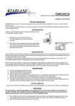
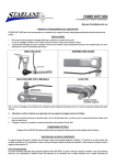
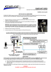
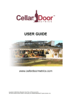
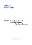
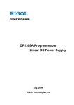
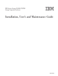
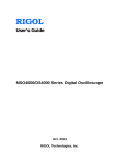
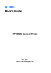
RIGOL Service Guide DS4000 Series Digital Oscilloscope Mar. 2012 RIGOL Technologies, Inc. RIGOL Guaranty and Declaration Copyright © 2012 RIGOL Technologies, Inc. All Rights Reserved. Trademark Information RIGOL is a registered trademark of RIGOL Technologies, Inc. Publication Number SGA10101-1110 Notices RIGOL products are protected by patent law in and outside of P.R.C. RIGOL reserves the right to modify or change parts of or all the specifications and pricing policies at company’s sole decision. Information in this publication replaces all previously corresponding material. RIGOL shall not be liable for losses caused by either incidental or consequential in connection with the furnishing, use or performance of this manual as well as any information contained. Any part of this document is forbidden to be copied or photocopied or rearranged without prior written approval of RIGOL. Product Certification RIGOL guarantees this product conforms to the national and industrial standards in China. International standard conformance certification is in progress, e.g. ISO. Contact Us If you have any problem or requirement when using our products, please contact RIGOL Technologies, Inc. or your local distributors, or visit: www.rigol.com. DS4000 Service Guide I RIGOL Safety Requirement General Safety Summary Please review the following safety precautions carefully before putting the instrument into operation so as to avoid any personal injuries or damages to the instrument and any product connected to it. To prevent potential hazards, please use the instrument only specified by this manual. Use Proper Power Cord. Only the power cord designed for the instrument and authorized by local country could be used. Ground The Instrument. The instrument is grounded through the Protective Earth lead of the power cord. To avoid electric shock, it is essential to connect the earth terminal of power cord to the Protective Earth terminal before any inputs or outputs. Connect the Probe Correctly. Do not connect the ground lead to high voltage since it has the isobaric electric potential as ground. Observe All Terminal Ratings. To avoid fire or shock hazard, observe all ratings and markers on the instrument and check your manual for more information about ratings before connecting. Use Proper Overvoltage Protection. Make sure that no overvoltage (such as that caused by a thunderstorm) can reach the product, or else the operator might expose to danger of electrical shock. Do Not Operate Without Covers. Do not operate the instrument with covers or panels removed. Use Proper Fuse. Please use the specified fuses. Avoid Circuit or Wire Exposure. Do not touch exposed junctions and components when the unit is powered. Do Not Operate With Suspected Failures. If you suspect damage occurs to the instrument, have it inspected by qualified service personnel before further operations. Any maintenance, adjustment or replacement especially to circuits or accessories must be performed by RIGOL authorized personnel. II DS4000 Service Guide RIGOL Keep Well Ventilation. Inadequate ventilation may cause increasing of temperature or damages to the device. So please keep well ventilated and inspect the intake and fan regularly. Do Not Operate in Wet Conditions. In order to avoid short circuiting to the interior of the device or electric shock, please do not operate in a humid environment. Do Not Operate in an Explosive Atmosphere. In order to avoid damages to the device or personal injuries, it is important to operate the device away from an explosive atmosphere. Keep Product Surfaces Clean and Dry. To avoid the influence of dust and/or moisture in air, please keep the surface of device clean and dry. Electrostatic Prevention. Operate in an electrostatic discharge protective area environment to avoid damages induced by static discharges. Always ground both the internal and external conductors of the cable to release static before connecting. Handling Safety Please handle with care during transportation to avoid damages to buttons, knob interfaces and other parts on the panels. DS4000 Service Guide III RIGOL Safety Terms and Symbols Terms in this Manual. These terms may appear in this manual: WARNING Warning statements indicate the conditions or practices that could result in injury or loss of life. CAUTION Caution statements indicate the conditions or practices that could result in damage to this product or other property. Terms on the Product. These terms may appear on the Product: DANGER WARNING CAUTION indicates an injury or hazard may immediately happen. indicates an injury or hazard may be accessible potentially. indicates a potential damage to the instrument or other property might occur. Symbols on the Product. These symbols may appear on the product: Hazardous Voltage IV Please Refer to Manuals Protective Earth Terminal Chassis Ground Test Ground DS4000 Service Guide RIGOL DS4000 Series Overview Being a multifunctional and high performance digital oscilloscope, DS4000 provides superb specifications and various functions, which in combination with its easy-to-use design can help users to fulfill their tasks (such as measurement and remote control) more quickly. Main features: 500 MHz, 350 MHz, 200 MHz and 100 MHz bandwidth. Dual-channel or 4-channel model. 4 GSa/s maximum real-time sample rate and 110,000 wfms/s (dots display) maximum waveform refresh rate. 140 Mpts maximum memory depth (standard). Ultra Vision technology. 9.0 inches, WVGA (800*480) 160,000 color TFT LCD, with ultra-wide screen, vivid picture, low power consumption and long service life. Enable to identify probe type automatically. Adjustable brightness of analog channel waveform. Auto setting of waveform display (AUTO). Various trigger functions including multiple protocol triggers. Standard parallel decoding and multiple serial decoding options. Auto measurements of 22 waveform parameters and measurement functions with statistic. Real-time waveform recording, waveform playback, record open (constant on) and waveform analysis. Precise delayed sweep function. Built-in FFT function. Pass/Fail test function. Multiple waveform math operation functions. Standard configuration interfaces: USB Device, dual USB Host, LAN and GPIB (optional). Support USB storage device and printer. Conform to LXI-C instrument standards. Enable quick, economic and efficient creation and reconfiguration of test system. Support remote command control. Embedded help enables easier information access. Support multiple languages and Chinese/English input. Provide shortcut keys for measurement, storage and print. DS4000 Service Guide V RIGOL Contents Guaranty and Declaration .......................................................................... I Safety Requirement ................................................................................. II General Safety Summary ............................................................................ II Safety Terms and Symbols ......................................................................... IV DS4000 Series Overview ........................................................................... V Chapter 1 Disassemble and Assemble .................................................. 1-1 Disassemble and Assemble Notices ............................................................ 1-1 Outside View Drawing of the Instrument .................................................... 1-2 Disassemble the Rear Cover ...................................................................... 1-3 Disassemble the Rear Metal Cover ............................................................. 1-4 Disassemble the Fan&Power Socket ........................................................... 1-5 Disassemble the Power Supply&Interface Board.......................................... 1-6 Disassemble the Front Panel&Knobs .......................................................... 1-7 Disassemble the LCD&Patch Board ............................................................ 1-9 Disassemble the Keyboards..................................................................... 1-10 Disassemble the Main Board ................................................................... 1-11 Assemble Procedures ............................................................................. 1-12 Chapter 2 Troubleshooting&Maintenance ............................................ 2-1 Troubleshooting ....................................................................................... 2-1 Maintenance............................................................................................ 2-3 System Maintenance .......................................................................... 2-3 Warranty .......................................................................................... 2-3 General Care and Cleaning ................................................................. 2-4 VI DS4000 Service Guide Chapter 1 Disassemble and Assemble RIGOL Chapter 1 Disassemble and Assemble Disassemble and Assemble Notices Notices: Do not disassemble the instrument unless for working requirement. Only authorized personnel can disassemble the instrument. Cut off the power supply before disassembling the instrument. Please wear anti-static wrist strap or make other anti-static precaution when disassembling the instrument. Please use proper tools and follow the correct steps. Take care not to deform the metal structure and be scuffed when disassembling the metal structures. Tools Required: Phillips screw driver T10 BNC socket 5mm hexagonal socket WARNING Make sure that the power supply is cut off before disassembling the instrument. Only personnel with relative training or relative qualification certification can disassemble the instrument. DS4000 Service Guide 1-1 RIGOL Chapter 1 Disassemble and Assemble Outside View Drawing of the Instrument The figure below is the outside view drawing of DS4000 (four-channel). You need to get a basic understanding of the main parts of the instrument before disassembling and assembling the instrument. When disassembling or assembling the instrument, please follow the procedures and take care not to scratch the surfaces of the parts. The recommended disassemble procedures are as follows. Disassemble the Rear Cover → Disassemble the Rear Metal Cover → Disassemble the Fan&Power Socket → Disassemble the Power Supply&Interface Board → Disassemble the Front Panel&Knob → Disassemble the LCD&Patch Board → Disassemble the Keyboards → Disassemble the Main Board Figure 1-1 DS4000 Outside View Drawing 1-2 DS4000 Service Guide Chapter 1 Disassemble and Assemble RIGOL Disassemble the Rear Cover ① Rear Cover ① ② Figure 1-2 Disassemble the Rear Cover Part Explanations: ① 2 screws (#FM3*10 torx countersunk head screw) at the handle groove. ② 2 screws (#FW3*8 torx pan head screw assembly) at the bottom of the cover. Dsiassemble Steps: 1. 2. 3. Remove the 2 screws (①) on the handle using the screw driver (T10). Remove the 2 screws (②, one on each side) at the bottom using the screw driver (T10). Take off the rear cover gently. DS4000 Service Guide 1-3 Chapter 1 Disassemble and Assemble RIGOL Disassemble the Rear Metal Cover ① ① ① ① Rear Metal Cover Figure 1-3 Disassemble the Rear Metal Cover Part Exaplanation: ① 8 screws (#FM3*6 torx countersunk head screw) fixing the front metal panel and rear metal cover. Disassemble Steps: 1. 2. Remove the 8 screws (①, 3 on top and bottom respectively, 1 on each side) fixing the front metal panel and rear metal cover using the screw driver (T10). Remove the AC power cord, rear interface board power cord and data cable on the main board before taking off the rear metal cover. Tip Insert the cord into the corresponding interface on the main board before assembling the rear metal cover. 1-4 DS4000 Service Guide Chapter 1 Disassemble and Assemble RIGOL Disassemble the Fan&Power Socket Fan Power Socket ② ① Figure 1-4 Disassenble the Fan and Power Socket Part Explanations: ① 2 screws (#M3*10 countersunk head torx machine) fixing the power socket. ② 4 screws (#PTF5*10 torx countersunk head self tapping screw) fixing the fan. Disassemble Steps: 1. 2. Remove the 2 screws (①) fixing the power socket using the screw driver (T10). Remove the 4 screws (②) fixing the fan using the screw driver (T10). Tip Pay attention to the direction of the fan when installing the fan. DS4000 Service Guide 1-5 Chapter 1 Disassemble and Assemble RIGOL Disassemble the Power Supply&Interface Board Power Supply ① ① ① ① Interface Board ② ② ② Figure 1-5 Disassemble the Power Supply and Interface Board Part Explanations: ① 4 screws (#M3*10 pan head torx machine) fixing the power supply. ② 3 screws (#FW3*6 torx pan head screw assembly) fixing the rear interface board. Disassemble Steps: 1. Remove the two nuts and washers at the BNC port at the rear metal cover using the BNC socket. 2. Remove the DB9 screws (imperial) at both sides of the RS232 interface using the socket (5mm hexagonal socket). 3. Remove the 4 screws (①) fixing the power supply using the screw driver (T10). 4. Remove the 3 screws (②) fixing the rear interface board using the screw driver (T10). 1-6 DS4000 Service Guide Chapter 1 Disassemble and Assemble RIGOL Disassemble the Front Panel&Knobs ② ② ② ② ③ ① Knobs Figure 1-6 Disassemble the Front Panel and Knobs Part Explanations: ① 13 knobs. ② 6 screws (#FW3*8 torx pan head screw assembly) fixing the front panel. ③ 2 screws (#FM3*6 torx countersunk head screw) fixing the front panel. Dsiassemble Steps: 1. Remove the 13 knobs at the front panel. 2. Remove the 6 screws (②) fixing the front panel using the screw driver (T10). 3. Remove the 2 screws (③) fixing the front panel using the screw driver (T10). DS4000 Service Guide 1-7 RIGOL Chapter 1 Disassemble and Assemble Tip a) b) 1-8 When removing the knobs, you are recommended to prize out the knobs using tools similar to the lever. Besides, it is recommended to place a soft washer at each force-bearing point to avoid damaging the button film and knobs. When the button film is removed, the stickness of the glue reduces and repeated use would result in unreliable paste. Therefore, if you only want to view the main board, disassembling the rear metal cover is enough and you are not recommended to disassemble the front panel. DS4000 Service Guide Chapter 1 Disassemble and Assemble RIGOL Disassemble the LCD&Patch Board Patch Board ① ① ① ① ② ① LCD ① Figure 1-7 Disassemble the LCD and Patch Board Part Explanations: ① 6 screws (#FW3*8 torx pan head screw assembly) fixing the LCD. ② 2 screws (#M3*6 countersunk head torx machine) fixing the patch board. Disassemble Steps: 1. Remove the 6 screws (①) fixing the LCD using the screw driver (T10). 2. Pull out the screen line connecting the patch board. 3. Remove the 2 screws (②) fixing the patch board using the screw driver (T10) and pull out the screen line connecting the main board. DS4000 Service Guide 1-9 Chapter 1 Disassemble and Assemble RIGOL Disassemble the Keyboards ① ① ① ① ① ① ① ② ① Figure 1-8 Disassemble the Keyboard Part Explanation: ① 9 screws (M3*6 countersunk head torx machine): 2 screws fixing the left and right keyboards respectively, 5 screws fixing the main keyboard. ② 4 screws (M3*6 torx pan head) fixing the probe patch board. Disassemble Steps: 1. Remove the 4 screws (①) fixing the left and right keyboards using the screw driver (T10). 2. Remove the 5 screws (①) fixing the main keyboard using the screw driver (T10). The screw positions are not shown completely in the figure above, please remove them according to their actual positions. 1-10 DS4000 Service Guide Chapter 1 Disassemble and Assemble RIGOL Disassemble the Main Board ① ① ① ① ① ① ① ① ① Figure 1-9 Disassemble the Main Board Part Explanation: ① 22 screws (#FW3*6 torx pan head screw assembly) fixing the main board and front metal panel. Disassemble Steps: 1. Remove the 4 screws (②, Figure 1-8) fixing the BNC patch board using the screw driver (T10). 2. Remove the nuts and washers (5 for four-channel models and 3 for dual-channel models) at the BNC port at the front metal panel using the BNC socket. 3. Remove all the 22 screws (①) fixing the main board and front metal panel using the screw driver (T10). The screw positions are not shown completely in the figure above, please remove them according to their actual positions. Tip Pass the keyboard-to-main board cable, front BNC-to-main board cable and the screen line through the corresponding holes on the front metal panel, fasten the main board and insert each cable into the corresponding position. DS4000 Service Guide 1-11 RIGOL Chapter 1 Disassemble and Assemble Assemble Procedures The assemble procedures are the reverse of the disassemble procedures. Check whether the cables are correctly connected and whether all the screws are installed after each step of assemble. You are recommended to follow the order and method introduced above when disassembling and assembling the instrument to avoid damage to the instrument due to improper operation and to save your time. 1-12 DS4000 Service Guide Chapter 2 Troubleshooting&Maintenance RIGOL Chapter 2 Troubleshooting&Maintenance Troubleshooting The commonly encountered failures and their solutions are listed below. When you encounter those problems, please solve them following the corresponding steps. If the problem remains still, please contact RIGOL and provide your device information (acquisition method: Utility System System Info). 1. The screen is still dark (no display) after power on: (1) Check whether the power is correctly connected. (2) Check whether the power switch is really on. (3) Check whether the fuse is burned out. If the fuse needs to be changed, please return the instrument to the factory and the RIGOL authorized personnel will change the fuse for you. (4) Restart the instrument after finishing the above inspections. (5) If it still does not work correctly, please contact RIGOL. 2. The signal is sampled but no waveform of the signal is displayed: (1) Check whether the probe is correctly connected to the signal connecting wire. (2) Check whether the signal connecting wire is correctly connected to the BNC (namely channel connector). (3) Check whether the probe is correctly connected to the item to be tested. (4) Check whether r there are signals generated from the item to be tested (you can connect the probe compensation signal to the problematic channel to determine which has problem, the channel or the item to be tested). (5) Resample the signal. 3. The tested voltage amplitude is greater or lower than the actual value (note that this problem usually occurs when probe is used): Check whether the attenuation coefficient of the channel complies with the attenuation ratio of the probe. 4. There is waveform display but not stable: (1) Check the trigger signal source: check whether the Source item at the trigger panel complies with the signal channel actually used. (2) Check the trigger type: general signals should use “Edge” trigger and video signal should use “Video” trigger. Only when the proper trigger type is used, can the waveform be displayed stably. (3) Try to change the Coupling to “HF Reject”or “LF Reject” to filter out the high-frequency or low-frequency noise that disturbs the trigger. (4) Change the trigger holdoff setting. DS4000 Service Guide 2-1 RIGOL Chapter 2 Troubleshooting&Maintenance 5. No display after pressing RUN/STOP: Check whether the MODE at the trigger panel (TRIGGER) is on “Normal” or “Single” and if the trigger level exceeds the waveform range. If yes, set the trigger level to the middle or set the MODE to “Auto”. Note: using AUTO could automatically finish the above setting. 6. The display of waveform is ladder-like: (1) The horizontal time base might be too low. Increase the horizontal time base to increase the horizontal resolution and improve the display. (2) If the display Type is “Vectors”, the lines between the sample points may cause ladder-like display. Set Type to “Dots” to solve the problem. 7. Fail to connect PC through USB: Check the IO Setting in Utility to make sure whether the setting in USB Device matches the device currently connected. If needed, restart the oscilloscope. 8. The USB storage device can not be recognized: (1) Check whether the USB storage device can work normally. (2) Make sure that the USB storage device being used is flash storage type. This oscilloscope does not support hardware storage type. (3) Make sure whether the capacity of the USB storage device is too large. It is recommended that the capacity of the USB storage device being used with this oscilloscope is no larger than 4 GBytes. (4) Restart the instrument and then insert the USB storage device to check it. (5) If the USB storage device still can not be used normally, please contact RIGOL. 2-2 DS4000 Service Guide Chapter 2 Troubleshooting&Maintenance RIGOL Maintenance System Maintenance In order to ensure the performance and prolong the service life of the instrument, please follow the recommendations below. 1. Get a full understanding of the performance and basic operating method of the instrument before using it. 2. In order to ensure the measurement accuracy and the service life of the instrument, the instrument should be used and stored in places away from dust, shock, moisture, magnetic field and static; besides, the instrument should be placed in places where it will not be exposed to sunlight for long periods of time. 3. Do not operate the instrument when failure occurs. In this situation, you need to first solve the failure. Besides, regular test and calibration should be performed to ensure the accuracy of the performance. 4. Arrange the instrument properly after you finish the operation of the instrument. 5. Keep the relative accessories of the instrument properly for future use. Warranty RIGOL warrants that its products mainframe and accessories will be free from defects in materials and workmanship within the warranty period. If a product is proven to be defective within the respective period, RIGOL guarantees the free replacement or repair of products which are approved defective. To get repair service, please contact with your nearest RIGOL sales and service office. RIGOL does not provide any other warranty items except the one being provided by this summary and the warranty statement. The warranty items include but not being subjected to the hint guarantee items related to tradable characteristic and any particular purpose. RIGOL will not take any responsibility in cases regarding to indirect, particular and ensuing damage. DS4000 Service Guide 2-3 Chapter 2 Troubleshooting&Maintenance RIGOL General Care and Cleaning General Care: Do not store or leave the instrument in where the instrument will be exposed to direct sunlight for long periods of time. Cleaning: Clean the instrument regularly according to its operating conditions. To clean the exterior surface, perform the following steps: 1. Disconnect the instrument from all power sources. 2. Clean the loose dust on the outside of the instrument with a lint- free cloth (with a mild detergent or water). When cleaning the LCD, take care to avoid scarifying it. CAUTION To avoid damages to the instrument, do not expose them to liquids which have causticity. WARNING To avoid injury resulting from short circuit, make sure the instrument is completely dry before reconnecting to a power source. 2-4 DS4000 Service Guide