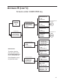
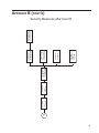
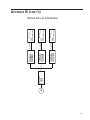
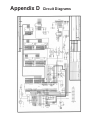
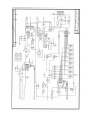
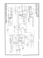
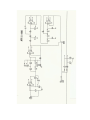
1
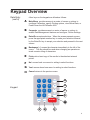
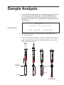
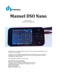
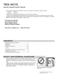
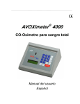
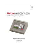
Operator's and Service Manual
U.S. Patent No. 5,430,542, 6,262,798 and 6,519,025 and Euro/UK Patent 0663070
Table of Contents
Topic
General Precautions
Introduction to the AVOXimeter 4000
System Components
Getting Started Keypad Overview
Installation and Operation
Software Features
Sample Collection and Preparation
Sample Analysis
Sample Printouts
Settings
Computer key Settings
Main Menu key Settings
Calibration and Quality Control
Optical QC Filters
Liquid QC
Proficiency Testing
Maintenance
Theory of Measurement
Troubleshooting
Specifications
Appendix A: Printer Information
Appendix B: Menu Flowcharts
Appendix C: ASTM Output
Warranty and Service
Appendix D: Circuit Diagrams
Index
Rev 9.06
Page
3
4
5
7
8 9
10
12
13
15
16
16
23
28
28
30
31
32 35
37
42
43
44
51
55
56
61
General
Precautions
2
!
1.
Do not allow untrained or an unauthorized personnel to use this instrument.
2.
This instrument will give accurate readings only if the cuvettes are at
room temperaure and the temperature probe is near the cuvettes. 3.
Do not attempt to use this instrument outside the recommended temperature range: 15°C - 30°C (59°F - 86°F). Do not place this instrument in air
currents or thermally unstable surroundings. Do not warm the cuvettes in
your hand.
4.
Do not allow blood, water, or other liquids to enter the instrument itself.
5.
Cuvettes are not sterile. Blood exposed to the cuvette should not be
returned to the patient.
6.
Do not re-use the cuvettes; discard after each use.
7.
Always keep cuvettes in sealed bag with desiccant.
8.
When filling cuvette, do not use excessive pressure or cause the vent
patch to bulge outward. Do not insert a cuvette if the vent patch protrudes; discard it.
9.
Do not leave a cuvette in the oximeter. Remove the cuvette as soon as
the sample has been analyzed.
10.
For proper calibration, use only the hemoglobin controls recommended in
this manual. Controls from other sources yield erroneous results.
11.
Use this instrument only with the AC adapter (battery charger) supplied
by ITC.
12.
Do not use this instrument in the presence of flammable agents or anesthetics.
13.
Operator should take appropriate precautions when handling potentially
infectious blood samples.
Introduction
The AVOXimeter 4000 is intended for professional use in settings in which rapid, accurate measurements are needed of the total hemoglobin concentration and the relative concentrations of oxy-, carboxy-, and methemoglobin. Direct analyte values are
obtained in 10 seconds. In addition, oxygen content (O2Ct) is automatically calculated
and available on the printout and data output. The AVOXimeter 4000 is a light-weight, portable instrument that is calibrated at the
factory prior to shipment. Optical technology (patent pending) and disposable cuvettes
enable the AVOXimeter 4000 to make its measurements six to ten times faster than
standard co-oximeters and eliminate the extensive care associated with their use. No sample preparation is required. Analysis is quickly accomplished by injecting the
whole blood sample into a disposable cuvette and inserting the cuvette into the instrument. The AVOXimeter 4000 then illuminates the sample with multiple wavelengths,
records the optical absorbance of the sample at each wavelength, and computes the
results. In 10 seconds, the total hemoglobin concentration and the relative concentrations of oxy-, carboxy- and methemoglobin are shown in appropriate units on the liquidcrystal display on the front panel.
The total hemoglobin concentration measured by the AVOXimeter 4000 includes oxy-,
deoxy-, met- and carboxyhemoglobin:
tHb = [O2Hb] + [HHb]+ [MetHb] + [COHb]
Accordingly, the percentage of oxyhemoglobin reported by the AVOXimeter 4000 is
%O2Hb
=
[O2Hb] x 100
[O2Hb] +[HHb]+ [MetHb] + [COHb]
The fractions of carboxy- and methemoglobin are defined in a similar manner.
In the U.S., the AVOXimeter is classified as "moderately complex" under the CLIA
NOTE test categorization. System Components
The AVOXimeter 4000 system consists of the following components:
• AVOXimeter 4000
• AC adapter
• Single-use cuvette (ordered separately) • Temperature probe
• Optical QC filters • Operator's Manual
(yellow and orange)
• Printer (optional)
AVOXimeter 4000 (front view)
Includes AC adapter and Operator's Manual (not shown)
AVOXimeter 4000 (rear view)
showing handle, serial port, AC
adapter port, and temperature
probe (connected).
System Components (cont'd)
Optical QC filters
Cuvettes
Optional printer
Getting Started
Precautions
only the AC adapter (battery charger) supplied by ITC, 1. Use
PN 9692 (110 VAC) or PN 9671 (220 VAC).
2. The instrument should not be used in the presence of flammable
agents.
3. For accurate readings, the cuvettes must be stored at room temperature (15-30°C) near the temperature probe connected to the
instrument. Do not place the instrument in air currents or thermally unstable surroundings.
4. Do not allow blood or other liquids to enter the instrument itself.
5. Blood exposed to the cuvette should never be returned to the
patient because the cuvettes are not sterile.
A
B
Front Panel
(A) Slot for cuvette
insertion.
1
2
3
Cancel
(B) Keypad for data
entry.
4
5
6
Yes
+
7
8
9
No
-
.
0
k
Print
(C) Liquid-crystal display or LCD.
Sample#1
tHb O2Hb COHb
17.0 39.7 56.6
g/dL
%
%
The display has four
lines, each with 20 characters.
MetHb
1.1
%
Main
Menu
Computer
Enter/On
C
Data Entry
Sample analysis does not require use of the numeric keypad until after the sample analysis is complete and prior to display of the results. After the analysis is complete, the software allows Sample Identification through selection or entry of numeric values.
Keypad Overview
Data Entry
(cont'd)
Keypad
Other keys on the keypad are utilized as follows:
A
Main Menu provides access to a series of menus or options to
configure Calibration, specify Printing options, view Stored Data, or
Power Down the AVOXimeter 4000.
B
Computer provides access to a series of menus or options to enable Data Management features and configure Device Settings.
C
Enter/On accepts selections. When the screen presents a menu,
press the appropriate number key to make your selection followed
by the Enter/On key to accept your selection and proceed to the next
screen.
D
Backspace [f] erases the character immediately to the left of the
cursor. This key should be used when changing an operator-entered numeric string of characters.
E
Print prints a hard copy of the results to the attached external printer.
F
No/- moves back one record or setting in select functions.
G
Yes/+ moves ahead one record or setting in select functions.
H
Cancel returns to the previous menu. 1
2
3
Cancel
H
4
5
6
Yes
+
G
7
8
9
No
-
F
.
0
�
Print
E
Main
Menu
Computer
A
B
Enter/On
D
C
Installation and Operation
Installation
1. Place the AVOXimeter 4000 on a stable surface away from drafts.
2. Plug the AC adapter (PN 9692 for 110 VAC, 60 Hz, or PN 9671
for 220 VAC, 50 Hz) into an appropriate electrical outlet . 3. Plug the external temperature probe into the designated socket
on the rear panel (see page 5). Ensure that the plug is firmly
seated.
4. Place the box of disposable cuvettes next to the instrument's temperature probe. Prior to use, the bag of cuvettes must be stored
near the temperature probe for a minimum of one hour at ambient
room temperature. Operation
5. Refer to Appendix A for printer information.
1. Turn on the instrument by pressing the Enter/On key.
2. Upon power-up, the AVOXimeter 4000 executes a self-test to
confirm the proper operation of its light sources. If the self-test
fails, the AVOXimeter 4000 will assist you in diagnosing the problem. For additional help, consult the Troubleshooting section of
this manual.
3. If the AVOXimeter 4000 passes the self-test, then the yellow and
orange optical filters may be analyzed to verify that its calibration has not changed. Each optical filter should be analyzed, at a
minimum, once each day the AVOXimeter 4000 is used to report
patient results. 4. If the optical filter readings are all within the established ranges,
then the system is ready to analyze patient samples (refer to page
13 for details). If any of the values are outside of the ranges, refer
to the Troubleshooting section.
Powering Down
1. To turn the AVOXimeter 4000 off, press the Cancel and Main
Menu keys simultaneously.
2. The AVOXimeter 4000 can also be turned off by pressing the
Main Menu key and selecting the Turn Off option.
Software Features
The software in the AVOXimeter 4000 has been specifically designed
to facilitate sample analysis yet provide optional features to assure
result integrity for patient reporting and to facilitate regulatory compliance. All operating parameter settings are stored in non-volatile
memory and are retained when the AVOXimeter 4000 is powered
down.
Security
Enabling the Security feature requires entry of a valid numeric User
ID before performing tests or accessing data in the AVOXimeter
4000. These numeric User IDs must be predefined by the QA User
through the Data Management Menu, User ID option. Enabling the
Security feature also provides the option to suppress printing of the
User ID on the result printout. When the option to print the User ID
is disabled, a labeled line on the printout provides space for writing in
the User ID manually.
User ID
When Security is disabled, a User ID option allows entry of a nonvalidated numeric operator ID. This eliminates the need to enter a
valid User ID before accessing functions on the AVOXimeter 4000 and satisfies regulatory requirements for recording the operator who
performed the test. Because these IDs are not secure, using this
mode for recording operator IDs automatically includes the User ID
on the printout. Disabling the User ID completely bypasses the User
ID entry option.
Sample Identification
The software requires the operator to distinguish between a patient
and QC sample prior to result display. When Security is disabled,
following completion of sample analysis, the AVOXimeter 4000
guides the operator through entry or selection of the following information about the sample just analyzed:
A. Operator ID, if User ID is enabled.
B. Sample type, either Patient or QC
1. If the sample type is patient, the patient ID, if enabled.
2. If the sample type is QC, the type of QC, either optical or liquid.
a. If the QC type is optical, the Yellow or Orange filter
b. If the QC type is liquid, the level, the material lot(s) predefined for the level, and verification of the predefined Cuvette Lot number or entry of the new Cuvette Lot number.
10
Software Features (cont'd)
Default Settings
The AVOXimeter 4000 is shipped from the factory with the following
default settings:
User ID
Off
Security
Off
Patient ID
Off
Data Transfer
Off
Auto Print
Off
Printer Baud Rate
9600
Printer Parity
None
Standby Delay
30 min.
Backlight
MEDIUM
tHb units
g/dL
Hüfners Number
1.39
Please refer to the Settings section of this manual for additional options and instructions to modify the above settings or define values
for data entry that cannot be established at the factory, such as Cuvette Lot number, QC Material Lot numbers, and Cuvette Cal Code.
11
Sample Collection and
Preparation
Sample Collection
To obtain accurate measurements, collect blood samples in a sodium or lithium heparinized plastic syringe. Collect and handle the specimens
according to medically-accepted sterile techniques, including the use
of universal precautions.
Collection Sources
of error
1. When drawing blood samples with a syringe from a saline-filled
catheter, withdraw the saline first and make sure that only whole
blood is sampled. 2. Citrate is known to change the pH of the blood and cause errors in
spectrophotometric measurements. Similarly, fluoride and oxalate
should be avoided.
3. Excessive volumes of anticoagulant or saline may oxygenate the
sample or cause dilution errors.
Sample Preparation
1. Roll the tightly sealed syringe between your palms to keep the red
blood cells and plasma well mixed. Poorly mixed samples or those
containing clots may cause inaccurate results.
2. When handling cuvettes, hold them only by their black caps. 3. To avoid warming the cuvette, do not pick it up until you are ready to fill it and analyze the sample.
4. Always fill cuvette prior to inserting it into the instrument. Preparation
Sources of error
1. Always store cuvettes in the sealed bag with a desiccant pouch or
erroneous results may occur. Check the desiccant prior to using
cuvettes to ensure that the color indicator has not changed from
blue to pink. If the color indicator has changed, do not use cuvettes
until a new desiccant pouch can be added to the bag. Prior to use,
verify indicator is blue. 2. When filling a cuvette, do not use excessive pressure or cause the
vent patch to bulge outward. If the vent patch protrudes, discard the
cuvette. To avoid contaminating the optics, never insert a cuvette
with a protruding vent patch into the instrument.
3. If the sample in the cuvette is poorly mixed or contains clots, then
discard the cuvette to prevent erroneous results.
12
Sample Analysis
1. Confirm that the temperature probe is plugged firmly into its socket
on the rear panel of the instrument. Press the Enter/On key to
turn on the AVOXimeter 4000 and confirm that the self-test was
successful. The instrument is ready to analyze samples when the
display reads: - - - R E A D Y - - -
I n s e r t C u v e t t e
Ready Screen
C a l C o d e = 4 4 4 4 5
2. Verify that the Cal Code is correct for the cuvette bag in use. If
not, refer to page 23.
3. Collect and prepare the heparinized blood sample as described on
page 12 or prepare the control sample as described on the package insert for the control.
Hold cuvette by
black cap
Bubble here is OK
Light Path
Vent patch
Side View
(Do not let patch bulge)
13
Sample Analysis (cont'd)
4. Expel one drop of sample from syringe and connect sample-filled,
plastic syringe to a new disposable cuvette.
5. Hold cuvette downward at 45° angle and inject sample into cuvette
until sample reaches the vent patch at the opposite end. Leave
the syringe attached to the cuvette. CAUTION!
Never force sample into cuvette. If cuvette does not fill easily, discard it and use another one.
6. Confirm that the light path at the widest portion of the sample
chamber is free of debris or air bubbles. Ignore bubbles outside
of the light path (see page 13).
7. Remove any blood on cuvette's exterior surfaces before inserting cuvette into the AVOXimeter 4000. Do not overpressure the
cuvette or cause the vent patch to bulge outward.
8. Insert cuvette within 10 seconds of filling it.
CAUTION
Never inject blood or any other material into the instrument
itself.
9. Observe the LCD display. At the screen prompt, remove the cuvette and select the sample type.
10. After the sample information is entered, the results will be displayed as follows: S a m p l e # 1
NOTE
t H b 1 7 . 0
O 2 H b 3 9 . 7
g / d L
%
C O H b M e t H b 5 6 . 6
1 . 1
%
% 11. After the results appear, the data will stay on the display until the
Enter/On key is pressed. Data will be stored in non-volatile memory
(100 samples) and may be recalled using the Stored Data menu.
12. To analyze the next sample, obtain a fresh cuvette from the bag
next to the instrument, and repeat the previous eleven steps.
14
Sample Printouts
Liquid QC with User ID On
Optical QC with User ID On
Optical QC with User ID Off
AVOXimeter 4000
Liquid QC Test
S/N: 41017
AVOXimeter 4000
Optical QC Test
S/N: 41017
AVOXimeter 4000
Optical QC Test
S/N: 41017
Tested on
05/24/05 07:43
Tested on
05/24/05 07:43
Tested on
05/24/05 07:43
Test Number 390
975310
2
754191
tHb
O2Hb
COHb
MetHb
14.1
94.5
2.3
1.0
O2Ct
18.6
Test Number 392
Test Number 393
User ID
Control Level
QC Lot Number
Measured
g/dL
%
%
%
Calculated
mL/dL
Cal. Code
Cuvette Lot
User ID
Optical Filter
975310
Orange
tHb
O2Hb
COHb
MetHb
17.0
39.3
21.3
1.0
O2Ct
9.3
41878
103095
Measured
g/dL
%
%
%
Calculated
mL/dL
Not Entered
Yellow
tHb
O2Hb
COHb
MetHb
8.0
95.2
1.6
0.7
O2Ct
10.5
Measured
g/dL
%
%
%
Calculated
mL/dL
__________________________________
User ID
A-VOX Systems, Inc.
A-VOX Systems, Inc.
User ID
Optical Filter
A-VOX Systems, Inc.
Liquid QC with User ID Off
O2Ct
Patient ID Off & User ID On
AVOXimeter 4000
Liquid QC Test
S/N: 41017
AVOXimeter 4000
Patient Test
S/N: 41017
AVOXimeter 4000
Patient Test
S/N: 41017
Tested on
05/24/05 07:43
Printed on
05/27/05 09:03
Tested on
05/24/05 07:43
Test Number 391
Tested on
05/24/05 07:43
Test Number 395
User ID
Control Level
QC Lot Number
tHb
O2Hb
COHb
MetHb
Patient ID On & User ID On
14.1
94.5
2.3
1.0
18.6
Not Entered
2
754191
Measured
Calculated
Cal. Code
Cuvette Lot
g/dL
%
%
%
A-VOX Systems, Inc.
User ID
Patient ID
864201
357912468035
mL/dL
tHb
O2Hb
COHb
MetHb
12.5
95.0
2.3
0.3
41878
103095
O2Ct
16.5
__________________________________
User ID
User ID
Patient ID
Test Number 394
Measured
Calculated
Cal. Code
g/dL
%
%
%
mL/dL
41878
__________________________________
Patient Name
A-VOX Systems, Inc.
975310
Not Entered
tHb
O2Hb
COHb
MetHb
12.4
95.4
1.9
0.2
O2Ct
16.5
Measured
Calculated
Cal. Code
g/dL
%
%
%
mL/dL
41878
__________________________________
Patient Name
__________________________________
Patient ID
A-VOX Systems, Inc.
15
Settings
The Computer and Main Menu keys activate the configuration and
data access features of the AVOXimeter 4000. The following section
describes the options available from these keys. For a quick reference, Appendix B contains a hierarchy of the configuration menu
structure. Options under the Main Menu key begin on page 23.
Computer
When the Computer key is pressed, the following menu is displayed:
1. Data Management
2. Device Settings
3. Time,Date,Temp
Data Management
Selection of choice 1 from the Computer menu displays the Data
Management menu options:
1.Data TransferON/OFF
2.User ID ON/OFF
3.Patient ID ON/OFF
4. QC Lot
Data Transfer
ON
The purpose of this feature is to provide the option to send the
AVOXimeter's data out the serial port using both the ASTM format
and communication protocol. Selection of this option displays the
current status (On or Off) and allows the operator to leave the status
as currently displayed or select the alternate status.
When ON, option ‘3. Transfer Data’ appears on the Stored Data
menu. Selecting the Transfer Data option from the Stored Data
menu, sends result records out the serial port via the attached RS232 cable, using the ASTM Standard Specification for Transferring
Information Between Clinical Instruments and Computer Systems,
E1394-91, as it applies to the specific data generated by the AVOXimeter 4000 and the ASTM Specification for Low-Level Protocol to Transfer Messages Between Clinical Laboratory Instruments
and Computer Systems, E1381-91. 16
Computer Settings (cont'd)
Data Transfer (Cont'd)
ON
Please refer to Appendix C for output format specific to data generated by the AVOXimeter 4000. The output contains a flag indicating
that a record has been previously sent.
OFF
When OFF, option ‘3. Transfer Data’ no longer appears on the Stored
Data menu and disables the ability to transfer results to another device such as a computer.
User ID
The purpose of this feature is to allow optional entry of the operator
ID in either a secure or non-secure mode. Selection of this option
displays the current status and allows the operator to leave the status as currently displayed or select the alternate status. ON When User ID is turned ON or the current ON status is acknowledged, the operator is presented with the Security ON/OFF menu. Please see the following section for a discussion of the Security
options. When the User ID is ON and Security is OFF, the operator of the AVOXimeter is prompted for entry of the User ID at the
completion of sample analysis, but prior to the results display. In
this configuration, the AVOXimeter 4000 accepts either a validated
or non-validated User ID or no User ID. Leaving the User ID blank
displays ‘USR Not Ent.’ on the Stored Data result display. Leaving
the User ID blank prints ‘User ID Not Entered’ on the result printout
and provides a blank line for writing in the User ID manually. OFF
When User ID is OFF, the operator is not given the option to enter
User ID following the completion of sample analysis. A sample analyzed with User ID OFF displays ‘USR Not Ent.’ on the Stored Data
result display, prints 'User ID Not Entered’ on the result printout,
and provides a write-on capability at the bottom.
Security
NOTE
The purpose of this feature is to require entry of a valid numeric User
ID before allowing access to the AVOXimeter 4000 functions. Selection of this option displays the current status and allows the operator to leave the status as currently displayed or select the alternate
status.
Following five minutes of inactivity, the AVOXimeter 4000 automatically returns to the Enter User ID screen when Security is ON.
17
Computer Settings (cont'd)
Security (Cont'd)
ON
Review/Delete
When Security is turned ON or the current ON status is acknowledged, the following menu is displayed:
1. Review/Delete
2. Add User
3. Print User List
4. Print ID ON/OFF
This option displays a list of secure User IDs. The numeric User
ID for the QA User which never displays or prints is 123456. The
literal ‘QAUSER’ prints or displays in place of 123456. Though the
screen display includes the option to 'Delete This ID', the ID for the
QA User cannot be deleted. An attempt to delete this ID results in
an error message. Cancel or option ‘1. Return to PrevMenu’ returns to the previous
menu. Option ‘2. Delete This ID’ presents a confirmation screen to confirm
deletion of the ID unless it belongs to the QA User.
Yes/+ displays the next secure numeric User ID.
No/- displays the previous secure numeric User ID.
Add User
NOTE
Print User List
This option allows entry of a new numeric User ID from one to nine
digits in length. If the User ID entered already exists, a message
is displayed and the User ID is not added. If the User ID does not
already exist, it is added to the list of secure User IDs.
The AVOXimeter 4000 allows definition of 50 secure User IDs. An
attempt to add more than 50 secure User IDs results in an error
message.
If an external printer is connected, this option prints a list of secured
User IDs currently defined in the AVOXimeter 4000.
18
Computer Settings (cont'd)
Print ID
ON
OFF
This feature determines if the secured User IDs print on the result
printout. Selection of this option displays the current status and allows the operator to leave the status as currently displayed or select
the alternate status.
When ON, the secured User ID prints on the printout.
When OFF, and Security is ON, the secured User ID does not print
on the printout, rather the printout includes User ID write-on capability at the bottom.
When Security is turned OFF or the current OFF status is acknowledged, entry of a valid numeric User ID is no longer required to operate the AVOXimeter 4000. When Security is turned Off, User IDs will
be printed on the result printout for both new and recalled tests.
Patient ID
ON
The purpose of this feature is to allow optional entry of the patient
ID. Selection of this option displays the current status and allows
the operator to leave the status as currently displayed or select the
alternate status. When Patient ID is ON, the operator of the AVOXimeter is prompted
to enter the Patient ID at the completion of sample analysis, but prior
to the results display. In this configuration, the AVOXimeter 4000 accepts entry of a one to twelve digit numeric Patient ID.
Leaving the Patient ID blank displays ‘Pt. ID: Not Entered’ on the
Stored Data result display, prints ‘Patient ID Not Entered’ on the
result printout and provides a write-on capability at the bottom.
OFF
When Patient ID is OFF, the operator is not given the option to enter
Patient ID following the completion of sample analysis. A sample
analyzed with Patient ID OFF displays ‘Pt. ID: Not Entered’ on the
Stored Data result display, prints ‘Patient ID Not Entered’ on the result printout and provides a write-on capability at the bottom.
19
Computer Settings (cont'd)
QC Lot
Select Level
Select Lot
The purpose of this feature is to allow definition of the QC Lot
Number(s) associated with Levels 1, 2, or 3 once they have been
accepted for use within the organization. Following completion of sample analysis, but before result display, the operator is
asked to identify the sample type. If the sample type is Liquid
QC, the screen for Level selection appears, followed by the Lot
Numbers predefined using this feature for the selected level. This feature allows for definition of three lot numbers per level. During sample identification, only those previously defined will
appear for operator selection.
Following selection of the QC Lot option, the following menu appears.
Select Level:
1. Level 1
2. Level 2
3. Level 3
The lot numbers defined for the level selected are displayed. Select the Lot number to be changed or deleted. The QC Lot
confirmation screen displays the Lot Number selected. Option 1. Cancel or OK to accept the Lot Number displayed.
Option '2. Enter New Value' presents a Lot Number entry
screen. Enter a new Lot Number from one to seven numeric digits in length or press Enter/On to delete the previous Lot Number. Entry of a new Lot Number requires confirmation. Deletion
of a Lot Number automatically shifts the remaining Lot Numbers
up one selection on the Select Lot screen. When specifying Lot
Numbers, ignore leading letters and leading zeroes.
Device Settings
Selection of choice 2 from the Computer menu displays the following Device Settings menu:
1. LCD
2. Units
3. Standby Delay
20
Computer Settings (cont'd)
Device Settings (Cont'd)
LCD
This feature allows the operator to adjust the brightness of the LCD
backlighting. Selection of this option from the Device Settings menu
displays the following backlighting options:
1. Backlight OFF
2. Backlight LOW
3. Backlight MEDIUM
4. Backlight HIGH
Enter the selection number and press Enter/On to adjust the backlighting to the operating environment. The screen immediately adjusts to the brightness selected. Continue to adjust the backlight via
number selection until the desired backlighting is achieved. Press
Cancel from the backlight options menu to return to the Device Settings menu. Units
This feature allows the operator to change the current tHb units
displayed. The options are g/dL or mmol/L. Selection of this option
displays the current status and allows the operator to leave the status
as currently displayed or select the alternate status
Standby Delay
Standby mode allows you to minimize the drain on the batteries yet
keep the AVOXimeter 4000 turned on so it can quickly resume analysis. This mode draws very little power and thus extends the operating time to several days with a fully charged battery. The AVOXimeter 4000 will automatically go into Standby Mode after
‘n’ minutes of inactivity, where ‘n’ is the value defined.
The AVOXimeter 4000 will not go into Standby Mode when performing analyses or executing functions unless the battery voltage is
critically low. If the battery voltage is critical, the AVOXimeter will immediately enter Standby Mode and prompt the operator to plug in the
charger. To resume operation, hold down any key for approximately
one second.
Selecting this option displays the current Standby Delay in minutes
and allows the operator to leave the status as currently displayed or
enter a new Standby Delay.
The valid entries are 10 to 180 minutes. Use 0 to disable the Standby
Delay feature.
NOTE
Entry of a value greater than 0 but less than 10 automatically defaults
to 10.
21
Computer Settings (cont'd)
Time, Date, Temp
Set & View Time
Selecting choice 3 from the Computer menu displays the following Time, Date, Temp menu:
1. Set & View Time
2. Set & View Date
3. Temp & Battery
This feature allows viewing and changing the AVOXimeter's internal clock. Selection of this option displays the current time
and allows the operator to leave the time as currently displayed
or set the clock to a new time. NOTE
The operator is not required to enter leading zeros, but must
enter trailing zeros; the AVOXimeter 4000 automatically adds
leading zeros to create the time in the format HHMM. For example, entry of 1 automatically defaults to 0001.
NOTE
The AVOXimeter 4000 does not automatically adjust for Day
Light Savings Time.
Set & View Date
NOTE
Temp & Battery
This feature allows viewing and changing the AVOXimeter's internal calendar. Selection of this option displays the current
date and allows the operator to leave the date as currently displayed or enter a new date in the format MMDDYY. The AVOXimeter 4000 presents an error message when the day entered is
greater than 31. The AVOXimeter 4000 automatically adjusts for leap year.
This feature presents the current power or battery status and
temperature in both °C and °F. If the AVOXimeter is connected
to the battery charger, the battery status will not be shown. Instead, "Connected to AC" will appear. Pressing Cancel or
Enter/On from the status display returns to the previous menu.
22
Main Menu Settings
Main Menu
Pressing the Main Menu key on the keypad displays the following
menu:
1. Calibration
2. Printer Mode
3. Stored Data
4. Turn Off
Calibration
Selecting the Calibration option from the Main Menu displays the
following Calibration menu:
1. Cuvette Cal Code
2. Cuvette Lot Number
3. Hüfner’s # 1.30-1.39
Cuvette Cal Code
Each package of cuvettes is labeled with a cuvette Calibration
Code used by the AVOXimeter 4000 to obtain correct measurements. The currently defined Cuvette Cal Code is displayed on
the Ready screen for visual verification each time a sample is
analyzed. Selecting the Cuvette Cal Code option from the Calibration Menu
displays the Cal Code currently defined. Press Cancel or OK to
leave the Cal Code as currently displayed, or change the current
value. When a new Cal Code is entered, the AVOXimeter 4000
automatically compares it with an internal table of acceptable
codes. After entering a five digit numeric Cal Code, the operator
must confirm the entry in a subsequent display. Upon acceptance,
the AVOXimeter verifies that the entry is a valid Cal Code and
presents an error message if the Cal Code entered does not match
one of those defined by the manufacturer.
Cuvette Lot Number
The Cuvette Lot Number is stored with the liquid QC results to
facilitate regulatory compliance and the recall of Stored Data. Selecting the Cuvette Lot Number option from the Calibration
Menu displays the Cuvette Lot Number currently defined. Press
Cancel or OK to leave the Cuvette Lot Number as currently displayed or change the current value. The Cuvette Lot Number can
also be changed following completion of analysis during collection
of sample information. When entered during sample information
entry, the new Cuvette Lot Number re-displays the existing Cuvette
Lot Number stored in the AVOXimeter 4000’s non-volatile memory. Entry of a one to seven digit numeric Cuvette Lot Number redisplays the entry for confirmation.
23
Main Menu Settings (cont'd)
Hüfner's Number Hüfner’s Number, the constant (k) in the following equation, is used
to compute the oxygen content (O2Ct) of each sample: O2Ct = k x tHb x %O2Hb / 100.
Selecting the Hüfner’s Number option from the Calibration Menu
displays the currently defined value of Hüfner’s Number. Press Cancel or OK to leave Hüfner’s Number as currently displayed or
enter a new value. To eliminate keying errors, the AVOXimeter
4000 allows entry of only the final digit. Entry of 0 to 9 redisplays
the entry for confirmation. Selecting the Printer Mode option from the Main Menu displays the
following menu:
1. Auto Print ON/OFF
2. Print Stored Data
3. Printer Parameters
Printer Mode
Auto Print
The AVOXimeter 4000 includes a feature to automatically print
results following sample analysis.
Selecting the Auto Print ON/OFF option from the Printer Mode
menu displays the current status. Press Cancel or OK to leave the
status as currently displayed or change the status to the alternate
value.
ON
When Auto Print is ON, the AVOXimeter 4000 automatically prints
results upon completion of sample analysis and collection of sample information.
OFF
When Auto Print is OFF, the AVOXimeter 4000 prints results only
when the Print key is pressed.
Print Stored Data
This function prints all results stored in the AVOXimeter 4000,
beginning with the most recent sample. Upon selection of the
function, the ‘Printing # XXXXXX’ displays, where XXXXXX is the
sample number currently printing. Press the Cancel key to stop printing. When Cancel is pressed
before all samples have printed, a message will be displayed stating that not all results have printed.
24
Main Menu Settings (cont'd)
Printer Parameters
This function configures the serial port for compatibility with the
external printer. Both the baud rate and parity can be adjusted. However, the data bits are fixed at 8 and the stop bits are fixed at
1.
When the Printer Parameters are selected from the Printer Mode
menu, the currently defined baud rate and parity are displayed. Pressing Cancel leaves the values as currently displayed; changes can be made as described below.
Baud Rate
The default baud rate is 9600 bps. The available baud rates are
110, 300, 600, 1200, 4800, 9600 and 19200 bps.
Enter/On
Yes/+
No/-
Parity
leaves the baud rate as displayed and moves the cursor to the parity value.
displays the next available baud rate.
displays the previous available baud rate. The default parity is NONE. The available parity options are
NONE, EVEN, ODD.
Enter/On leaves the parity as displayed and presents a confirmation screen for both baud rate and parity values.
Yes/+
displays the next available parity value.
No/-
displays the previous available parity value. NOTE
Stored Data
If you change the serial port configuration for the printer and also
use the Transfer Data function, verify that the receiving system can
accommodate the current serial port configuration. If not, change
the serial port configuration before and after executing the Transfer
Data function.
The Stored Data function displays and prints existing AVOXimeter
4000 results. Upon selection of the Stored Data option from the
Main Menu, the following menu is displayed:
1. Select Sample #
2. Newest Sample
3. Transfer Data (if Data Transfer is ON)
Use +/- to Scroll
25
Main Menu Settings (cont'd)
Stored Data (cont'd)
Select Sample #
This function allows reviewing and printing selected results by specifying the sample number. The AVOXimeter 4000 automatically increments the sample number by one for each new successful sample
analysis. The sample number will increment to 999999 before it must
be reset. Upon selection of this function, the AVOXimeter 4000 displays the currently available range of sample numbers.
Newest Sample
This function automatically displays results for the most recent successful sample analysis.
Yes/+ Key
Pressing this key automatically displays the results for the first (oldest) sample stored in the AVOXimeter 4000.
No/- Key
Result Display
Pressing this key automatically displays results for the last (newest) sample stored in the AVOXimeter 4000. The result display is the same as the display following sample analysis and entry of sample information. However, because the result
display does not provide sample information, the Enter/On key toggles between two display modes: results and sample information. The sample information display contains the following information:
Display line one contains
Display line two contains
Display line three contains
Display line four contains
Sample number and User ID
Patient ID (if sample type = Patient)
Optical filter (if sample type = Optical QC)
Level and Lot (if sample type = Liquid QC)
Cuvette Lot Number if the sample type =
Liquid QC
Blank if the sample type is Patient or
Optical QC
Cal Code if the sample type = Patient
or Liquid QC
Sample type (Q for QC or P for Patient ) on the
right side if Data Transfer is ON
Transfer status also on the right side (S for sent
and N for not sent) if Data Transfer is ON
26
Main Menu Settings (cont'd)
Result Display (cont'd)
Enter/On Toggles to the alternate display mode.
Yes/+
No/-
Pressing this key automatically displays either results
or sample information for the next sample number. The display mode is determined by the display mode of
the last sample number.
Pressing this key automatically displays either results
or sample information for the previous sample number. The display mode is determined by the display mode of
the last sample number.
Cancel Returns to the Stored Data menu.
Transfer Data
If the Data Transfer option is turned ON (see page 16), this function transfers results in an ASTM format via the serial port to the
connected information system. Each result contains a flag indicating if it has previously been sent. Upon selection of this function, a confirmation screen is displayed.
Yes/+ Begins the data transfer. If the cable is not connected properly or the port is not configured accurately or the receiving
system is not ready to receive data, the transfer process will
‘time out’ and display a message that the transfer process
has terminated. Verify the connection, port configuration on
both systems, the readiness of the receiving system, and
attempt the transfer again.
No/- Terminates the data transfer and returns to the Stored Data
menu.
Turn OFF
Selecting this function powers down the AVOXimeter 4000.
27
Calibration and Quality Control
GENERAL
The initial calibration of the AVOXimeter 4000 is set at the factory. Recalibration is required only if the daily functional checks with the
yellow and orange optical filters do not meet the established specifications. Recalibration, if necessary, will be performed at ITC.
The most frequent cause of error messages or erroneous readings
is not loss of calibration, but contamination of the optical detector
with blood or other debris. The optical filters are used to quickly and
conveniently determine whether the optics have been contaminated
and to verify that the calibration has not changed.
NOTE
Because they verify calibration, these procedural checks meet the
CLIA requirement §493.1202 which states that the user must “perform and document calibration procedures at least once every six
months”.
NOTE
These procedural checks not only verify that the instrument is properly calibrated, but also confirm the optical detector is not contaminated by any debris.
Quality Control
Materials
OPTICAL QC
NOTE
Recommendation
for Optical QC
Two types of controls are available for use on the AVOXimeter 4000:
1. Optical QC filters (yellow and orange)
2. Liquid control materials such as IL's Multi-4™ CO-Oximeter Controls or RNA Medical's RNA CC 527 or CVC 223.
Each AVOXimeter 4000 is equipped with cuvette-shaped yellow and
orange optical QC filters that can be inserted into the instrument to
simulate a blood sample of known composition. Each filter has a serial number that matches the serial number of the AVOXimeter 4000
with which it is used.
If you have two or more AVOXimeter 4000 analyzers, their optical filters cannot be used interchangeably. Each set of yellow and orange
optical QC filters can be used only with the AVOXimeter 4000 of the
same serial number. The manufacturer recommends that quality control testing with both
optical filters be performed:
• on each analyzer once each day of patient testing
• when an analyzer is brought from a hot to a cold temperature or
vice versa
• whenever the performance of the analyzer requires verification
28
Optical QC (Cont'd)
Optical QC To conduct the daily QC and calibration verification with optical filters:
Procedure 1. Confirm that the filters have the same serial number as the
AVOXimeter 4000.
2. Wait until the READY message appears on the display.
3. Remove any debris from the surface of the optical filters by
wiping them with dry gauze prior to inserting them into the
AVOXimeter.
4. Insert the filter into the cuvette slot and enter the sample
information at the prompt. 5. Verify that each of the results is within the established range
for the filter. Proceed with the other filter if each value is
within range.
NOTE
Optical QC Ranges
Discontinue using the device for clinical purposes if any of the values are outside of the specified range and refer to the Troubleshooting section of the manual or contact Technical Support.
Analyte
Range for Yellow Filter Range for Orange Filter
tHb (g/dL)
tHb (mmol/L)
%O2Hb
%COHb
%MetHb
7.8
4.8
93.7
0.6
-0.4
to 8.2
to 5.1
to 96.3
to 3.4
to 2.4
16.7
10.4
37.8
20.0
0.2
to
to
to
to
to
17.3
10.7
40.2
23.0
1.8
29
Liquid QC
LIQUID QC
The purpose of liquid controls is to serve as another means to verify
that the AVOXimeter 4000 system is functioning properly.
Control materials compatible with the AVOXimeter 4000 are the IL
Multi-4™ CO-Oximeter Controls levels 1, 2, and 3 (800-955-9525),
(781-861-0710) or www.ilww.com and RNA CC 527 [levels 1 to 3]
or CVC 223 [levels 1 to 5] (800-533-6162), (978-772-9070) or www.
rnamedical.com. Other controls may give erroneous results.
The Multi-4™ controls are assayed hemoglobin solutions that require
refrigeration. The RNA controls are dye-based liquid controls that can
be stored at room temperature. When ordering, request a lot with "best
dating" to ensure the longest shelf-life possible.
NOTE
Recommendation
for Liquid QC
If QC ranges for the AVOXimeter 4000 are not listed on the insert
sheet of the IL Multi-4™ or the RNA CC 527 or CVC 223 controls,
call Technical Support (800-225-2869), (210-696-4149).
The manufacturer recommends periodic quality control testing with
liquid controls to:
• verify proper storage of cuvettes (weekly)
• verify proper shipping conditions before a new lot or shipment of
cuvettes is put into use
• verify the performance of the cuvettes as required
Liquid QC To conduct periodic QC and calibration verification with liquid conProcedure
trols:
NOTE
Prior to analyzing liquid controls, QC lot information must be defined
(refer to page 20).
1. Observe the manufacturer’s recommendations for storage, preparation, and handling of the control material.
2. Ensure that the temperature probe is firmly plugged into the
AVOXimeter 4000.
3. If the AVOXimeter 4000 is not powered up, press the Enter/On
key and wait for the Ready screen. 30
Liquid QC (Cont'd)
4. Verify cuvette Cal Code (page 23), fill cuvette with the control,
and insert the cuvette into the instrument.
5. Verify that results are within your facility's established ranges. If values are not within range, follow your facility's protocol.
CAUTION
Even if the AVOXimeter's readings with liquid QC materials fall
within the acceptable ranges specified on the insert sheets supplied with the liquid QC materials, the AVOXimeter can still give
spurious readings on whole blood if blood or other debris has gotten onto the light detector. To rule out this possibility, perform the
Optical QC Procedure with the yellow and orange filters.
PROFICIENCY
TESTING
Proficiency testing is a system by which laboratories can compare
the accuracy of their testing procedures and the proficiency of
their users with other laboratories. Federal regulations at this time
require that only the test system, assay, or examination used as
the primary method for patient testing participate in the proficiency
testing (§493.801). A full description of the proficiency testing
process may be found in Subpart H 42 CFR, Feb. 28, 1992 (CLIA
’88).
In the case of ancillary testing, if a testing facility performs the
same test using different methodologies or instruments, or performs the same test at multiple testing sites, the testing facility
must have a system that evaluates and defines the relationship
between test results biannually (§493.1709). The primary instrument enrolled in proficiency testing is used to compare all other
instruments.
Recommended
Surveys
The following proficiency surveys are compatible with the AVOXimeter:
American Proficiency Institute (API) Blood Oximetry #114-94
800-333-0958
College of American Pathologists (CAP)
Blood Oximetry Survey SO
800-323-4040
NOTE
Other proficiency surveys may give erroneous results.
31
Maintenance
MAINTENANCE
This section describes how to perform the following maintenance
procedures on the AVOXimeter 4000 system:
• Charging the battery
• Cleaning the analyzer
• Cleaning the optical QC filters
• Inserting printer paper
• Temperature probe calibration verification
Battery Power
The AVOXimeter 4000 can be powered either from its internal batteries or from the wall transformer that serves as a battery charger and
AC adapter. It can analyze blood samples and perform all of its other
functions using either power source. When the AC adapter is the power
source, the batteries will charge at the same time that blood samples
are analyzed.
Standby Mode
To maximize the operating time from a battery charge, the AVOXimeter
4000 has two modes of operation: Sample Analysis Mode and Standby
Mode. When the AVOXimeter 4000 is displaying its READY screen,
it is in the Sample Analysis Mode. This is the usual mode of operation
for analyzing samples, using various menus, and printing stored data. If
a sample is not analyzed, or a key is not pressed within a user-defined
time period, the AVOXimeter will go into Standby Mode to conserve its
battery charge. The Standby Delay can be set by pressing the Computer Key, selecting Device Settings, and selecting Standby Delay.
Standby Mode conserves battery power and extends the battery operating time without turning off the AVOXimeter 4000. Testing may
resume shortly after exiting Standby Mode. To exit, hold down any key
for approximately one second.
NOTE
If the battery voltage becomes critical, the AVOXimeter 4000 will immediately go into Standby Mode and will prompt the user to plug in
the charger.
32
Maintenance (Cont'd)
Battery Charge If the batteries are fresh and fully charged, the AVOXimeter 4000
Conservation can analyze blood samples continuously for 10-12 hours when the
display backlighting is set at MEDIUM. However, the operating time
per battery charge depends on a number of user-selectable factors. The following tips will help the user maximize the number of samples
that can be analyzed from a single battery charge:
1) Turning the display backlight off will conserve battery energy
and thus increase the operating time per battery charge. If the
backlight is needed, the LOW backlight setting is the next best
choice. Press the Computer key, select Device Settings, and
select LCD to set the level of backlighting.
2) Setting the Standby Delay to the shortest time (10 minutes) will
conserve battery energy by putting the AVOXimeter 4000 into
Standby Mode if it is not used for 10 minutes. Press the Computer key, select Device Settings, and select Standby Delay to
change the setting.
3) Ni-Cad batteries suffer from a "memory effect" if they are charged
before being completely discharged. To prevent "memory effect",
let batteries discharge completely before recharging. Batteries
are almost completely discharged when the "battery critical"
status screen is displayed.
Battery Status
Battery status can be checked by pressing the Computer key, selecting Time, Date, Temp, and selecting Temp & Battery. The battery
charge status will fall into one of four categories: High, OK, Low, or
Critical.
When the AVOXimeter 4000 is in the Sample Analysis Mode, the status
of the battery will be displayed on the LCD display when it becomes
critical. When the battery status becomes critical, the AVOXimeter
4000 will immediately go into Standby Mode and will prompt the user
to plug in the battery charger.
Analyzer Cleaning
NOTE
Clean the analyzer surface and screen with a soft cloth dampened with
isopropyl alcohol, distilled water, or 10% bleach solution. Immediately
wipe off any excess alcohol or accidental liquid spill. A cotton swab
may also be used to clean the outside of the cuvette slot as needed
(do not insert cotton swab into the analyzer). Do not use excessive force, strong detergent, concentrated bleach,
or abrasive cleaning solution because they can scratch or damage
the surface.
33
Maintenance (Cont'd)
Optical Filter Clean the surface of the optical filters with dry gauze to prevent
Cleaning scratching.
Printer Paper
Follow the printer manufacturer's directions for insertion of printer
paper.
Temperature The calibration of the temperature probe should be checked once
Probe Calibration every six months.
Verification
1. Obtain a thermometer calibrated to National Institute
for Standards in Technology (NIST) standards. The thermometer should be accurate to at least 0.5 °C.
2. Use rubber bands or adhesive tape to attach the bulb
end of the thermometer to the circular disk at the end of
the AVOXimeter temperature probe.
3. Make sure the probe and the thermometer are in a
thermally stable environment and not in air currents.
4. Wait 10 minutes.
5. Press the Computer key and select the Time, Date,
Temperature option. Then select the Temp & Battery option to display the temperature measured by the AVOXimeter.
6. Record the temperatures measured by the AVOXimeter and the thermometer.
7. If the AVOXimeter's reading is within ± 3 °C of the
NIST thermometer, the AVOXimeter is properly calibrated. If the AVOXimeter differs from the thermometer by
more than 3 °C, call Technical Support (800-225-2869) or
(210-696-4149).
34
Theory of Measurement
According to Beer's Law, if several light-absorbing compounds are present in a solution,
the concentration of each compound can be deduced if the compounds differ in their optical absorbances and if optical density is measured at as many wavelengths as there are
compounds present. For example, if three compounds X, Y, and Z are present and if the
optical density (OD) is measured at three different wavelengths (λ), the result is a set of
simultaneous equations with as many equations as there are unknown concentrations (c). Thus, if the optical pathlength (i) and the extinction coefficients (ε) are known, the concentrations, cx, cy, and cz can be computed from this set of equations:
ODλ1 = εx,λ1cxi + εy,λ1cyi + εz,λ1czi Equation 1
ODλ2 = εx,λ2cxi + εy,λ2cyi + εz,λ2czi Equation 2
ODλ3 = εx,λ3cxi + εy,λ3cyi + εz,λ3czi Equation 3
Conventional whole-blood oximeters use only two wavelengths to measure the relative
concentrations of two hemoglobin species: oxy- and deoxyhemoglobin. Thus, for a conventional whole-blood oximeter, the oxyhemoglobin saturation is defined as:
[O2Hb] %O [HHb] + [O2Hb]
2Hb =
x 100
Equation 4
where the total hemoglobin concentration is assumed to consist entirely of oxy- and deoxyhemoglobin. Consequently, if other hemoglobin species such as met- or carboxyhemoglobin are present in substantial concentrations, the conventional two-wavelength oximeter's
measurements of %O2Hb would be in error.
35
Theory of Measurement (Cont'd)
The AVOXimeter 4000 uses multiple wavelengths to obtain accurate measurements
of %O2Hb even if bilirubin and four different hemoglobin species are present in the
sample. Thus, for the AVOXimeter 4000, the value reported on the display for %O2Hb
is defined as:
%O2Hb =
[O2Hb]
x 100
Equation 5
[O2Hb] + [HHb]+ [MetHb] + [COHb]
Similar equations apply to %COHb and %MetHb. The AVOXimeter 4000 reports a value
for the total hemoglobin concentration that is the sum of the concentrations of oxy-, deoxy-, met- and carboxyhemoglobin:
tHb = [O2Hb] + [HHb]+ [MetHb] + [COHb]
Equation 6
Conventional whole-blood oximeters do not measure the total hemoglobin concentration
because whole blood does not really obey Beer's Law. Whole blood does not simply
absorb light; the red blood cells also scatter the light. Thus, conventional oximeters are
unable to measure the total hemoglobin concentration accurately. The AVOXimeter
4000 makes an assessment of the amount of light scattering in each sample, employs
proprietary optics and mathematical algorithms to correct its measurements, and thus
obtains accurate measurements of total hemoglobin concentration and percent oxy-,
carboxy- and methemoglobin.
In conventional whole-blood oximeters, the following can constitute major sources of
error:
a. hemolysis (which changes the amount of light scattering in the sample)
b. other light-absorbing compounds such as indocyanine green dye and bilirubin
c. other hemoglobin species including carboxyhemoglobin and methemoglobin
By using additional wavelengths, the AVOXimeter 4000 is able to measure four hemoglobin
species and to eliminate interference due to bilirubin. By making appropriate corrections
for the light scattering in each sample, the AVOXimeter 4000 yields accurate measurements regardless of the extent of hemolysis. Thus, the AVOXimeter 4000 is capable
of analyzing samples of whole blood, partially hemolyzed blood, and even hemoglobin
solutions. Finally, at the wavelengths used by the AVOXimeter 4000, indocyanine green
dye absorbs relatively little light. Thus, diagnostic concentrations (<10 mg/L) of indocyanine green dye produce minimal error (see Specifications).
36
Troubleshooting
If necessary contact Technical Support (800-225-2869) or (210-696-4149) for service assistance.
SYMPTOM
AVOXimeter fails to turn on.
AVOXimeter does not respond to cuvette insertion or
key presses or POSSIBLE CAUSE
Battery is discharged and AC
adapter is not plugged into AC
outlet.
Microprocessor is "locked up".
Display is blank with cursor
flashing.
Self-Test fails on power-up. 1. Cuvette is inserted in instrument.
"Cuvette Inserted???" shows
on LCD screen
2. If no cuvette is in instrument, then the intensities
may be out of range.
External printer not printing.
Message on LCD Reads:
ERROR: Temp < 15.0 C
or ERROR: Temp > 30.0 C
REMEDY
Connect AC adapter to
AVOXimeter 4000 and to AC
outlet.
Contact Technical Support.
1. Remove cuvette, turn power off and restart.
2. Contact Technical Support.
1. No power to printer.
1. Firmly plug cord into printer, connect to power and turn on.
2. Printer not connected to
AVOXimeter 4000.
2. Connect cable both to printer
and to AVOXimeter 4000.
3. "Auto Print" not selected,
or baud rate or parity is
wrong.
3. S et baud rate and/or parity on AVOXimeter 4000 and
on printer to same values (See p. 24-25).
4. Printer does not respond
or prints unintelligible
characters.
4.Contact Technical Support.
5. AVOXimeter 4000 is
locked up, i.e. fails to respond to cuvette insertion
or key presses.
5. Contact Technical Support.
1. Temperature probe absent or
not plugged in firmly.
1. Turn unit off, plug temperature
probe in firmly, turn on unit and
retry.
2. Temperature is outside operating range of 15-30°C
(59-86°F).
2. Bring environment to
proper temperature range. If error is persistent, then
contact Technical Support.
37
Troubleshooting (Cont'd)
SYMPTOM
%O2Hb, %COHb or
%MetHb measurements
are inaccurate.
POSSIBLE CAUSE
REMEDY
Detector surface is contaminated 1. Analyze optical filters. If valwith blood or other debris.
ues are within specifications,
detector is OK. Verify operator is using proper cuvette
handling and sampling technique.
2. Analyze optical filters. If values are outside of specification, contact Technical Support.
tHb measurements are 1. New box of cuvettes is being
inaccurate.
used, but cuvette Cal Code
has not been updated.
2. Incorrect Cal Code for current box of cuvettes was
entered.
3. Detector surface is contaminated with blood or
other debris.
4. tHb calibration has changed
Message on LCD Reads:
Microprocessor error.
1. Follow "Cuvette Cal Code"
instructions (p. 23).
2. Follow "Cuvette Cal Code"
instructions (p. 23)
3. Contact Technical Support.
4. Analyze optical QC filters, if
values are within specifications, detector is OK. Verify
user is using proper cuvette
handling and sampling technique. If values are outside of
specification, contact Technical
Support.
Contact Technical Support.
ERROR: Uninitialized Vector Service Required
38
Troubleshooting (Cont'd)
SYMPTOM
POSSIBLE CAUSE
REMEDY
Message on LCD Reads:
1. No sample in cuvette.
ERROR: tHb <> XX.X or
ERROR: %O2Hb <> XX.X% or
ERROR: %COHb <>XX.X% or
ERROR: %MetHb<>XX.X% or
ERROR: %HHb <> XX.X% or
ERROR: %Scat <> XX.X% or
followed by:
2. Cuvette is not properly filled. 2. Make sure sample reaches
vent patch.
3. Detector surface is contaminated with blood or other
3. Analyze optical QC filters. If
debris.
values are within specifications, detector is OK. Verify proper cuvette handling and
sampling technique is being
used.
"See Troubleshooting Section of Manual. ENTER to Continue."
1. Fill cuvette with sample.
If values are outside of
specification, contact Technical Support.
Note: If any of these errors occur, the sample data will not be stored.
4. LED intensities too low.
ERROR: tHb < 4.0 g/dL
Note: The sample data will not be stored.
tHb may actually be low. In
this case %O2Hb, %COHb &
%MetHb values may be inaccurate.
Not Applicable
ERROR: tHb > 25.0 g/dL
tHb may actually be high. In
this case tHb, %O2Hb, %COHb
& %MetHb values may be inaccurate.
Not Applicable
Note: The sample data will not be stored.
tHb, %O2Hb, %COHb or
%MetHb reading for optical
filter is out of range.
4. Turn off/on to see if Self-Test
fails. If failure occurs, then
contact Technical Support .
1. Detector surface is contaminated with blood or other debris.
1. Contact Technical Support.
2. C
alibration of instrument
has drifted.
2. Contact Technical Support. 39
Troubleshooting (Cont'd)
Disassembling the AVOXimeter and Cleaning the Detector
If you suspect that the optical unit has been contaiminated with blood, you may clean the detector of the
AVOXimeter by following these instructions.
You need the following tools for this procedure:
a. #0 phillips screwdriver
b. 5 mm nutdriver
c. 1/4" nutdriver
1. Disconnect the wall transformer from the AVOXimeter
and turn the unit off.
2. Turn the AVOXimeter upside down and remove the
four screws using the #0 phillips screwdriver.
3. Hold the upper and lower parts of the case
together, and turn the AVOXimeter right side up
again with the keypad to your right.
4. Slowly and carefully lift the upper part of the
case slightly, keeping it parallel with the lower
part.
5. Find the battery cable that runs from the battery
pack to the circuit board. Disconnect the battery
cable at the circuit board (JP301).
6. Tilt the top half of the case backward to gain access
to the front of the circuit board.
7. Find the keypad cable that runs from the keypad to
the circuit board. Disconect the keypad cable at the
circuit board (J101).
8. Find the flat LCD cable that runs from the LCD
to the circuit board (connector J102). Disconnect the LCD cable at the circuit board. CAUTION: Grasp the connector only and gently
rock in an upward direction.
9. Disconnect the LED cable that runs from the
black optical unit to the circuit board (J203), unplugging it at the circuit board . Disconnect the
coaxial detector cable that runs from the black
optical unit to the small circuit board (J1XX),
unhooking it at the circuit board end.
40
Troubleshooting (Cont'd)
10. Now turn the top half of the AVOXimeter's case
upside down so that you are looking directly at
the black optical unit. Using the 5mm nutdriver,
remove the four nuts (and washers, if applicable)
that hold the optical unit to the front panel, and
completely remove the optical unit from the instrument.
11. Using the 1/4" nutdriver, remove the four screws
and four nuts. Take care when separating the two
halves of the optical unit. Do not lose the small torsion spring or the shutter door. Set them aside in
a safe place for reassembly. 12. Clean the exposed detector with gauze pads
dampened with detergent. Do not use abrasives. Then dry off the detector surface,
making sure that it is clean. Remove any other
debris inside the optical unit.
13. Reassemble the two halves of the optical unit, making sure
that the shutter door and torsion spring are installed correctly
(the two door ribs will face outward). One leg of the spring
fits into a hole in the door slot, the other leg rests behind the
shutter door. Bolt the optical unit back together.
14. Reverse steps 1 through 10 to reassemble the AVOXimeter.
15. Turn on the instrument. The AVOXimeter should run its
self-test and display its READY screen. Reset time and date
(see Time, Date menu, p.22).
16. If the AVOXimeter fails its self-test or displays error messages, the most likely cause of the problem
is improper re-assembly, particularly cables not connected to the correct pins on their sockets (see
Troubleshooting).
41
Specifications
Measurements and Operating Ranges
total hemoglobin concentration (tHb)
oxyhemoglobin (O2Hb)
4 to 25 g/dL
0 to 100 %
carboxyhemoglobin (COHb)
0 to 75 %
methemoglobin (MetHb)
0 to 85 %
Calculated oxygen content (O2Ct)
0 to 35 mL/dL
Accuracy*
Precision**
total hemoglobin concentration (> 10 g/dL)
(< 10 g/dL)
0.45 g/dL
0.35 g/dL
0.3 g/dL 0.3 g/dL
oxyhemoglobin (O2Hb)
1.6 %
0.8 %
carboxyhemoglobin (COHb) 2 %
1%
methemoglobin (MetHb)
1.5 %
0.7 %
Sample
type
whole blood
volume
50 µl
Time per Sample
10 sec
Number of Wavelengths
7
Data Display
4 lines X 20 characters
Interference
tHb
%O2Hb
%COHb
%MetHb
bilirubin
none
none
<1%
<1%
none
none
<1%
<1%
(11mg/dL)
hemolysis
fetal hemoglobin (tHb = 13.5 g/dL, HbF=100%) <0.45g/dL <1%
0.06%/%HbF <1%
indocyanine green dye (<10mg/L)
<0.45g/dL <1%
<1%
methemoglobin
<0.2 g/dL <1%
<1%
(tHb = 16 g/dL, MetHb < 10%, 7.1 < pH < 7.8)
Dimensions
10 X 8 X 3.75 inches (25.4 x 20.3 x 9.5 cm)
Weight
4 lbs (1.8 kg)
Serial Port
RS232C
Battery
Ni-Cad
Battery Charger PN 9692 (110VAC), PN 9671 (220 VAC)
Approvals
UL 544, CE mark for EMC directive
Data Storage
100 samples in non-volatile memory
* Accuracy data were obtained by comparing the AVOXimeter 4000 with a reference co-oximeter. Specifications for accuracy
are Sy.x (standard error of the estimate) for the best-fit line determined by the method of least squares.
** Precision specification is based on the standard deviation of repeated analysis of the same sample.
42
Appendix A
PRINTER
The Dymo™ SE300 printer is a small, convenient thermal printer which
attaches to the AVOXimeter 4000 via a custom DB9 to RJ 11 (modular
plug) cable. The printer is powered by an AC adapter. Do not operate the printer
with any adapter other than the one provided.
Installation
Connect the cable supplied with the Dymo printer to the printer using
the RJ11 modular plug. Connect the DB9 connector to the serial port
on the rear panel of the AVOXimeter 4000. Secure the cable with the
screws. The baud rates of both the printer and the AVOXimeter 4000
are preset at the factory to 9600 bps. To verify or change the baud
rate settings on the AVOXimeter 4000, refer to page 25.
Serial Port
Pin-Out for the AVOXimeter 4000 Serial Port. The following diagram
explains the pin-out for the rear connector (DB9, male) of the AVOXimeter 4000 serial port. The connector is shown as viewed from the
back of the instrument.
Pin 1: NC
Pin 2: RXD (Input)
Pin 3: TXD (Output)
Pin 4: DTR (Data Term. Ready)
Pin 5: Signal Ground
Pin 6: NC
Pin 7: RTS (Ready to Send)
Pin 8: CTS (Clear to Send)
Pin 9: NC
43
Appendix B
Screens under MAIN MENU key
Calibration Menu
Pres the
MAIN MENU
key
1
1
Cuvette Cal Code:
*******XXXXX******
1. OK
2.Enter New Value
2
Cuvette Lot:
******XXXXXXX*****
1. OK
2.Enter New Value
3
Hüfnerʼs Number
1.39 ml O2 / g Hb
1. OK
2. Enter New Value
1. Cuvette Cal Code
2. Cuvette Lot Number
3. Hüfnerʼs# 1.30-1.39
Main Menu
1.
2.
3.
4.
Calibration
Printer Mode
Stored Data
Turn Off
Printer Mode Menu
2
1
1. Auto Print ON/OFF
2. Print Stored Data
3. Printer Parameters
2
1. OK
2. Turn ON
Printing #216
Please Wait...
CANCEL to Terminate
Instructions:
To make a selection
from any menu, press
the desired number
and then the Enter/On
key.
Press Cancel to return
to a previous menu.
Auto Print: OFF
3
Stored Data Menu
3
1. Select Sample #
2. Newest Sample
3. Transfer Data (*)
Use + / - to Scroll
* This line shown only if Data
Transfer turned on under Data
Management menu.
Turn Off
4
1
Baud Rate= 9600
Parity= NONE
Data Bits = 8 (Fixed)
Stop Bits = 1 (Fixed)
Show Sample # ____
Valid Range:
117 to 216
Sample #214
tHb
O2Hb COHb MetHb
2
17.0 35.4 >25 0.6
g/dL
%
% %
3
Transfer Data? [Y/N]
***POWERING DOWN*** Note: This selection does not require
pressing Enter/On to confirm.
44
Appendix B (cont'd)
Screens under COMPUTER key
Data Transfer: ON
1
Press the
COMPUTER
key
Data Management Menu
1
1. DataTransferON/OFF
2. User ID ON/OFF
3. Patient ID ON/OFF
4. QC Lot
2
3
Computer Menu
1. Data Management
2. Device Settings
3.Time, Date, Temp
4
Device Settings Menu
2
1. LCD
2. Units
3. Standby Delay
1
2
3
Press Cancel to return
to a previous menu.
Time and Date Menu
3
User ID: ON
1. OK
2. Turn OFF
See “Security Measures
After User ID”
A
Patient ID: ON
1. OK
2. Turn OFF
Select Level:
1. Level 1
2. Level 2
3. Level 3
1.
2.
3.
4.
See “Stored QC Lot
Information”
B
Backlight OFF
Backlight LOW
Backlight MEDIUM
Backlight HIGH
tHb Units : g / dL
Instructions:
To make a selection
from any menu, press
the desired number and
then the Enter/On key.
1. OK
2. Turn OFF
1
1. Set &View Time
2. Set &View Date
3. Battery Status
2
3
1. OK
2. Select mmol / L
Standby Delay in
Minutes: ****60****
1. OK
2. Enter New Value
(HHMM)
Time: 1816 (24 hr)
1. OK
2. Enter New Value
( MMDDYY)
Date: 042996
1. OK
2. Enter New Value
Temperature Battery
24.0C 75.2F
OK
ENTER When Done.
45
A
Security: ON
1. OK
2. Turn OFF
User ID: ON
1. OK
2. Turn OFF
1. Review/Delete
2. Add User
3. Print User List
4. Print ID ON/OFF
4
3
2
1
User ID on
Printout: OFF
1. OK
2. Turn ON
Please Wait...
Printing List...
Enter User ID:
*******
*******
(Up to 6 digits;
no leading zeros)
User ID: 999999
+/- to Scroll
1.Return to PrevMenu
2.Delete this ID
If 2
Are You Sure You
Want to Delete the
User ID 999999?[Y/N]
Appendix B (cont'd)
Security Measures after User ID
46
B
Select Level:
1. Level 1
2. Level 2
3. Level 3
QC Lot:
******
*******
1. OK
2. Enter New Value
QC Lot:
******
*******
1. OK
2. Enter New Value
1,2 or 3
L3 Select Lot:
1. UNDEFINED
2. UNDEFINED
3. UNDEFINED
QC Lot:
******
*******
1. OK
2. Enter New Value
1,2 or 3
1,2 or 3
L2 Select Lot:
1. UNDEFINED
2. UNDEFINED
3. UNDEFINED
L1 Select Lot:
1. UNDEFINED
2. UNDEFINED
3. UNDEFINED
Appendix B (cont'd)
Stored QC Lot Information
47
No
Security
On?
Turn
Instrument
On
Yes
Cal Code = 54321
- - - READY - - Insert Cuvette
Enter User ID:
*****
******
(Up to 9 digits;
no leading zeros)
Insert Cuvette
& Wait for
Prompt
Cal Code = 54321
- - - READY - - Insert Cuvette
User ID On?
Insert Cuvette
& Wait for
Prompt
Yes
2
Enter User ID:
*****
******
(Up to 9 digits;
no leading zeros)
1. Patient
2. QC
Select Sample Type
Q
(See Patient &
QC Information
Part 3)
P
(See Patient &
QC Information
Part 2)
1
Appendix B (cont'd)
Entry of Patient & QC Information Part 1
48
P
Patient ID
On?
Enter Patient ID:
****
****
(Up to 12 digits;
no leading zeros)
1
Sample #1
tHb O2Hb COHb MetHb
17.0 39.7 56.6
1.1
g/dL
%
%
%
1. OK
2. Re-enter
Pt.ID:XXXXXXXXXXX
2
Appendix B (cont'd)
Entry of Patient & QC Information Part 2
49
Q
1. Liquid
2. Optical
Select QC Type
2
1
1. OK
2. Re-enter
1. Yellow
2. Orange
2
XXXXXX Optical Filter
2
L# Select Lot:
1. XXXXXXX
2. XXXXXXX
3. XXXXXXX
Select Filter
Select Level
1. Level 1
2. Level 2
3. Level 3
1
Sample #1
tHb O2Hb COHb MetHb
17.0 39.7 56.6
1.1
g/dL
%
%
%
1
Level # Lot:XXXXXXX
Cuvette Lot:XXXXXXX
1. OK
2. Re-enter
1
Cuvette Lot:
******
*******
1. OK
2. Re-enter
2
Cuvette Lot:
*****
******
(Up to 7 digits;
no leading zeros)
Appendix B (cont'd)
Entry of Patient & QC Information Part 3
50
Appendix C
ASTM Output
The AVOXimeter 4000 features an ASTM output using the single RS-232 serial port. This allows transfer of the AVOXimeter 4000's results to an information system capable of receiving data utilizing the ASTM standard 1394-91; Standard Specification for Transferring Information Between Clinical Laboratory Instruments and Computer Systems and
ASTM standard 1381-91; Specification for Low-Level Protocol to Transfer Messages Between Clinical Laboratory Instruments and Computer Systems. The following is a brief description of the formatting of these data:
I. General Output Notes
1.
Each record consists of fields separated by the ‘vertical bar’ character ‘|’. (0x7C)
2.
Each record will end with the ‘<CR>’ character. (0x0D)
3.
Fields may contain components, separated with the ‘caret’ character ‘^’. (0x5E)
4.
Records are variable length.
5.
Records conform to the ASTM standard 1394-91; Standard Specification for Transferring Information Between Clinical Instruments and Computer Systems.
6.
Transmission conforms to ASTM standard 1381-91; Specification for Low-Level Protocol to Transfer Messages Between Clinical Laboratory Instruments and Computer Systems.
7. Records are transmitted from the AVOXimeter 4000 in reverse sample number sequence.
II. ASTM Record Types Used
H
Message Header Record
P
Patient Record
O
Order Record
M
Manufacturer Record
R
Result Record
L
Terminator Record
III. ASTM Record Types Not Used
C
Comments
Q
Request Information
S
Scientific
IV. Record Hierarchy
Header Record
Patient 1 Record
Order 1 Record
Manufacturer Record
Analyte 1 Result Record
Analyte 2 Result Record
...
Order 2 Record
...
Order ‘n’ Record
Manufacturer Record
Analyte 1 Result Record
Analyte 2 Result Record ...
Patient ‘n’ Record
Order 1 Record
Manufacturer Record
Analyte 1 Result Record
Analyte 2 Result Record
...
Terminator Record
51
Appendix C (cont'd)
V. ASTM Record Formats
Header Record
Field No.
1
2
3
4
5
5.1
5.2
5.3
6
7
8
9
10
11
12
13
14
Field Label
Record Type
Delimiters
Values
ʻHʼ
ʻ\^&ʼ
Message Control
Access Password
Sender Information -see below
Sender Name/ID
Software Version
Serial Number
Sender Street
Reserved
Sender Phone
Sender Characteristics
Receiver ID
Comments
Processing ID
E1394 Version No
Message Date/Time
Null
Null
ʻAVOXʼ
vX.X.X
XXXXX (5 digits)
Null
Null
Null
Null
ʻIDMSʼ
Null
ʻPʼ
ʻ1ʼ
YYYYMMDDHHMMSS
Additional Comments
Repeat delimiter,
component delimiter,
escape character
respectively
AVOX software version #
Analyzer serial number
Current Date and Time
Patient Record
Field No.
1
2
3
4
Field Label
Record Type
Sequence No
Values
ʻPʼ
1…#
Patient ID-Primary
Lab ID
Null
ʻQ.C. Testʼ, Patient ID
(up to 12 digits), or Null
Additional Comments
ʻnthʼ patient record in this
transmission set (between H
and L records)
If sample type = patient, then
patient ID entered or Null if
left blank. If sample type =
QC, then literal string ʻQ.C.
Testʼ
52
Appendix C (cont'd)
Order Record
Field No.
1
2
Field Label
Record Type
Sequence No
Values
ʻOʼ
1…#
3
4
5
Null
XXXXXX (up to 6 digits) Analyzer sample ID
5.1
5.2
5.3
5.4
Specimen ID
Instrument ID
Universal Test ID-see below
Univ. Test ID, Part 1
Univ. Test ID, Part 2
Univ. Test ID, Part 3
Universal Test ID, Part 4
6
7
8
9
10
11
Priority
Order Date/Time
Collection Date/Time
Collection End Time
Collection Volume
Collector ID
Null
Null
YYYYMMDDHHMMSS Test date and time
Null
Null
XXXXXXXXX or Null
ID of operator
(up to 9 digits)
performing test; Null if left blank
Null
Null
Null
XX
Additional Comments
ʻnthʼ order record in this patient
set (between P and P or P and L
record sets)
ʻA0ʼ if not Optical Filter
Yellow Optical QC = ʻA1ʼ
Orange Optical QC = ʻA2ʼ
Manufacturer Record
Field No.
1
2
3
4
5
Control Level
Values
ʻMʼ
ʻ1ʼ
XXXXX (5 digits) or Null
XXXXXXX (up to 7 digits)
or Null
Null or ʻ1ʼ, ʻ2ʼ, or ʻ3ʼ
6
Material Lot, i.e.
Control Lot Number
Hufner's Value
Optical QC Status
XXXXXXX (up to 7 digits)
or Null
1.3X (X from 0 to 9)
Null, ʻPASSʼ or ʻFAILʼ
7
8
Field Label
Record Type
Sequence No
Calibration Code
Cuvette Lot
Additional Comments
Null if Optical Filter
Null if Patient Data or Optical
Filter
If P record, field 4 does not =
ʻQ.C. Testʼ, then Null
Null if Patient Data or
Optical Filter
ʻPASSʼ or ʻFAILʼ if Optical Filter;
Null otherwise
53
Appendix C (cont'd)
Result Record
Field No.
1
2
Field Label
Record Type
Sequence No
3
Universal Test ID
- see below
Univ. Test ID, Part 1
Univ. Test ID, Part 2
Univ. Test ID, Part 3
Universal Test ID,
Part 4
Universal Test ID,
Part 5
3.1
3.2
3.3
3.4
3.5
4
5
6
7
8
9
Values
ʻRʼ
1…#
Data or
Measurement
Value
Units
Reference Range
Abnormal Flags
Nature of Abnormal
Testing
Result Status
Additional Comments
ʻnthʼ result record in this order set
(between O and O or O and L record
sets)
Null
Null
Null
ʻtHbʼ, ʻO2Hbʼ, ʻCOHbʼ, ʻ Analyte test ID,
MetHbʼ, ʻHHbʼ, ʻO2Ctʼ
predefined by the analyzer.
ʻMʼ or ʻCʼ
Measured value = ʻMʼ for: ʻtHbʼ,
ʻO2Hbʼ, ʻCOHbʼ, ʻMetHbʼ, ʻHHbʼ
Calculated value = ʻCʼ for: ʻO2Ctʼ
#####.###
Null, ʻg/dLʼ, ʻmmol/Lʼ, ʻ%ʼ
Null
Null
Null
ʻFʼ or ʻRʼ
If not previously sent= ʻFʼ
If previously sent = ʻRʼ
Terminator Record
Field No.
1
2
3
Field Label
Record Type
Sequence No
Termination Code
Values
ʻLʼ
ʻ1ʼ
ʻNʼ or ʻTʼ
Additional Comments
Normal = ʻNʼ
Sender aborted = ʻTʼ
54
Warranty and Service
ITC, declares to the original purchaser that each instrument manufactured and sold by ITC, or sold by an
authorized ITC dealer, shall be free from defects in material and workmanship and, under normal and proper
use conditions, warrants it for a period of one year from installation and no more than 13 months from the
shipping date, except as otherwise provided in writing.
ITC’s obligation is limited to repairing, replacing, or modifying (at ITC’s undisputed judgment) at ITC's
factory, or elsewhere, the material whose defects have been verified, on condition that the purchaser has
informed ITC of any defects found within 15 days from receipt. Damages caused by or connected to transport are excluded. Transport to and from ITC facility will be at purchaser’s charge and risk, and shall also be
prepaid for reshipment, except as otherwise provided in writing. These replacements, repairs, or alterations
will in no case determine extension to the above specified warranty period.
The warranty does not cover those parts that deteriorate, or which are in any case considered consumables,
or those parts or “items”, which by their nature are normally required to be replaced periodically consistent
with normal maintenance. It is also understood that, following the purchase and delivery of the instrument,
the purchaser shall be deemed liable for any losses, damages, or complaints concerning persons or things
incurred by the use, or misuse of the instrument, on behalf of the purchaser, its employees, co-operators, or
others. ITC does not assume any obligation or warranty engagement concerning precision and/or accuracy
of the measurements, as well as for any damage to the instrument, directly or indirectly resulting from the use
of reagents and/or consumables different from those produced by ITC specifically for its own instruments,
and for the same properly tested.
Warranty will not apply to those defective instruments or materials showing defects or damage arising
from the following causes:
1. Insufficient or negligent care by the purchaser.
2. Insufficient or negligent maintenance by the purchaser in relation to the instructions contained in the manuals
prepared by ITC for this purpose; tampering or alterations of the instruments, or in any case interventions
or repairs made by any person not duly authorized by ITC.
3. Misuse due to carelessness, negligence, or inexperience.
4. Employment of materials under heavier conditions than those for which they have been designed and
manufactured, and use of the same in combination with incompatible or dangerous products.
5. Non-observance of the regulations relevant to installation, power supply, and operation of the instruments
(with particular regard to the regulations for accident prevention).
THIS WARRANTY IS GIVEN EXPRESSLY AND IN LIEU OF ALL OTHER WARRANTIES, EXPRESS
OR IMPLIED. PURCHASER AGREES THAT THERE IS NO WARRANTY OR MERCHANTABILITY AND
THAT THERE ARE NO OTHER REMEDIES OR WARRANTIES, EXPRESS OR IMPLIED, WHICH EXTEND
BEYOND THE CONTENTS OF THIS AGREEMENT.
No agent or employee of ITC is authorized to extend any other warranty or to assume for ITC any liability
except as above set forth.
Please contact Technical Support, if any malfunction is discovered.
Emergo Europe
Molenstraat 15
2513 BH, The Hague
The Netherlands
Tel: (31) 70 345 8570
Fax: (31) 70 346 7299
55
Appendix D
Circuit Diagrams
Index
A
G
Q
AC adapter 3, 7
Air bubbles 13, 14
General Precautions 3
Getting Started 7
Quality Control 28-31
QC Lot 20
B
H
R
Batteries Charging 32
Conservation 21, 33
Replacement 3
Baud Rate 11, 25, 43
Bilirubin 36, 40
Hemolysis 36, 40
Ready Screen 13
RNA CC 527 Controls 28, 30
I
S
IL's Multi-4™ 28
Indocyanine green dye, ®
See Cardio-Green
Installation 9
Introduction 4-6
IRMA Capillary Collection Device 12
Sample Collection 12
Screen Backlighting
20, 21
Security 10, 17, 18
Self-test 9
Service 55
Standby Delay 20, 21
Standby Mode 32, 33
Stored Data 25-27
System Components 5, 6
C
Calibration Menu 23
Temperature Probe 34
Verification 28, 29
Optical Filters
Carboxyhemoglobin 35, 36 40
®
Cardio-Green , See indocyanine
green dye
Cleaning 33
CLIA Categorization 4
Computer key 8, 16, 45
Controls, See Quality Control
Cuvette
Cal Code 23
Lot Number23
Injection Technique 12-14
D
Data Entry 7,8
Data Management 16, 20
Data Transfer 16, 17
Default Settings 11
Deoxyhemoglobin 35, 36, 40
Desiccant 3
Device Settings 20
E
Enter/On key 8, 9
F
Fetal hemoglobin 40
Filters, See Optical QC Filters
Front Panel 7
K
Keypad 8
L
Light scattering 36
Liquid QC 30, 31
M
Main Menu 23-27
Main Menu key 8
Maintenance 32-34
Methemoglobin 35, 36, 40
O
Optical
Absorbance 35, 36
Contamination 29, 38
Density 35
QC 28, 29
QC Filters 5,6,9,10,28,29
Oxyhemoglobin 36
Oxyhemoglobin saturation 40
P
T
Table of Contents 2
Technical Support 37
Temperature Probe 5, 9, 13, 34
Temperature Operating Range 3
Theory of Measurement 35
Time, Date, Temp 22
Total hemoglobin 4, 35, 36, 40
Troubleshooting 37-41
Turn OFF 9, 27
U
Units 21
User ID 10, 17
V
Vent Patch 13, 14
W
Warranty 55
Wavelengths 36, 40
Patient ID 19, 48
Printer 6, 43
Printer Mode 24, 25
Printer paper 34
Proficiency Testing 31
61
Emergo Europe
Molenstraat 15
2513 BH, The Hague
The Netherlands
Tel: (31) 70 345 8570
Fax: (31) 70 346 7299