1
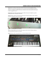
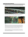
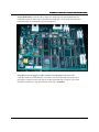
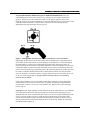
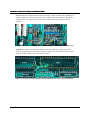
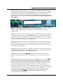
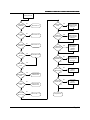
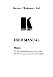
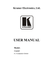
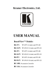
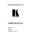
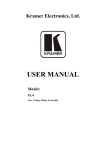
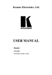
Europa Installation Instructions
Europa Installation Instructions
Copyright
Copyright © 1994-2001 Synthcom Systems, Incorporated. All rights reserved. No part of
this manual or CD-ROM (including cover design, illustrations, or interior design) may be
reproduced or transmitted in any form by any means, including but not limited to
electronic forms, photocopying, recording, or otherwise, without the prior written
permission of Synthcom Systems, Incorporated. Visit http://www.synthcom.com for
most current documentation, downloadable images, and support information.
Limit of Liability/D
Liability/Disclaimer of Warranty
Synthcom Systems, Incorporated and its representatives have used their best efforts in
preparing this CD-ROM and manual. Synthcom Systems, Inc. makes no representation or
warranties with respect to the accuracy or completeness of the contents of the CD-ROM
or files contained within it, and specifically disclaim any implied warranties or
merchantability or fitness for any particular purpose, and shall in no event be liable for
any loss of profit or any other commercial damage, including but not limited to special,
incidental, consequential or other damages. Synthcom Systems, Incorporated reserves the
right to update the files contained within this CD-ROM and is not required nor expected
to ship updated CD-ROMs to existing owners.
Trademarks
All brand names and product names used in this CD-ROM and manual are trademarks,
registered trademarks, or trade names of their respective holders. Synthcom Systems,
Incorporated is not associated with any product or vendor mentioned in this book, nor
does it necessarily endorse any product or vendor.
Europa Installation Instructions
Introduction
Welcome to the Europa upgrade for your Roland Jupiter 6! This document gives full
installation instructions for upgrading the master controller board for the Jupiter 6 (JP-6).
It is assumed that the reader has knowledge and experience with electronic hardware
and associated tools. It is critically important that the instructions are followed VERY
closely, as there are many small, but nonetheless important, details that are critical to the
success of the upgrade. Proficiency with a soldering iron and a steady hand are required,
so put down that cup of coffee! If you are not comfortable with the process documented
here, do not attempt to install it yourself!
NOTE: Synthcom Systems, Inc. cannot and will not be held liable for
third party installation that results in damage to the Europa chip itself,
the JP-6’s controller board, loss of patches, or any other part of the JP-6.
This includes information in this document that may lead to damage of
any part of the JP-6. Synthcom Systems, Inc. strives for accuracy in its
installation instructions and reserves the right to modify them at any
time for any reason. The installer assumes full responsibility for any
damage done – regardless of fault. Proceed at your own risk! It assumed
that the installer will read this document thoroughly before proceeding.
Do not attempt if unsure!
Conceptual description of upgrade
The Europa upgrade is a replacement for the existing 8031 (or 8051) in the JP-6’s
controller board. It’s a mostly pin compatible 40 pin DIP part (Temic T89C51RD2) that
includes onboard flash where the Europa code resides. Additional electronic changes are
documented below:
•
The 8031/8051’s !EA Is pulled high with a 1-10K ohm resistor allowing internal
code execution
•
Jumper removed to allow !EA to be strapped high
•
XTAL1 And XTAL2 Are reversed due to NMOS (original 8031/8051 chip type) to
CMOS conversion. NMOS Parts have pin 18 as the clock input and pin 19 as ground. The
upgrade connects the clock input to pin 19 and ground to 18.
•
Depending upon the version of the JP-6 controller board, the CPU may need to
be removed and a socket put it in its place.
Flash programming voltage is obtained through the standard 5-volt supply of the chip so
no additional jumpering is required.
Page 3
Europa Installation
Installation Instructions
Tools you will need
This is a required list of tools needed to accomplish the Europa upgrade:
•
•
•
•
•
•
•
•
•
•
•
Soldering iron
Tiny wire cutters (snips)
Xacto knife or equivalent
Desoldering tool (desoldering wick will not work well)
Flat or needle nosed pliers
Small flat blade screwdriver
Philips screwdriver
Ohmmeter
Pliers
Antistatic bag or antistatic mat – at least 8 inches by 12 inches
Safety goggles
The following tools are not necessary but will make the job much easier if they’re
available:
•
•
•
Moto-Tool or die grinder with wire brush
Small vice (rubber or plastic jaws only!)
Desoldering station
The following parts are included in the upgrade. Please verify they are present before
starting:
•
1 - Europa integrated circuit
•
2 - 1-10K Ohm resistors (only use one – an extra is included just in case the other
is lost)
•
1 – 40 Pin machine tooled socket
•
1 – 4 Inch wire. Must be small enough to wrap around soldered pins. Wire wrap
gauge recommended.
•
1 – Replacement battery (only present if it was ordered – it is optional!)
NOTE: If a Kenton Jupiter 6 upgrade is currently installed, it must first be removed
before Europa is installed. The two upgrades are not compatible and cannot coexist.
Page 4
Europa Installation Instructions
Get s
started!
tarted!
Step 1) Clear a work area where the controller board can be easily modified. Ensure
ahead of time that all aforementioned tools are present. Be sure to back up your patches
to tape or a computer’s sound card! Patches shouldn’t be lost in this process, but it’s good
to have a copy just in case.
Step 2) Unplug all cables from the JP-6. Power, MIDI, CV inputs, headphones, pedals –
anything that can be unplugged externally.
Step 3) Unscrew 3 screws on the left side of the JP-6 as shown in Figure 1 below (already
removed - pointed to by the green arrows)
Figure 1 – JP-6 Side panel screw locations
There is an equivalent set of 3 screws on the opposite side of the JP-6. Remove them as
well. Set them aside, and don’t lose them!
Step 4) Unscrew the 3 front panel screws as shown in Figure 2 below:
Figure 2 – JP-6 front panel screw locations
Page 5
Europa Installation
Installation Instructions
Step 5) Lift the control panel up – it is hinged at the rear of the JP-6. Be careful not to lift
the front panel so much that it stresses the wires pointed to by the green arrows in Figure
3!
Figure 3 – Jack board – Watch that wire stress!
Step 6) Give the front panel support on each side with something long and solid, such as
two screwdrivers or two 12” socket extensions. Anything to give the board support
without stressing/binding the wires on the jack board (shown in Figure 3).
Figure 4 – From left to right - 2 Voice board, controller (surrounded in green), and power
supply
Step 7) Locate the controller board. It’s the smaller board encircled in green in Figure 4.
Note that the picture may not exactly match the controller board encountered as there are
several versions. Don’t be alarmed if the controller board is slightly different from what’s
pictured! Unplug all connectors going to the controller board. Make note of where the
connectors go by labeling or taking a picture, as the connectors will need to be plugged
back into their original locations when the controller board is reinstalled.
Step 8) There are 4 screws at the 4 corners of the controller board. Unscrew them and set
the screws aside. NOTE: The screws are most likely secured with Loc-tite. Use a pair of
pliers to break the seal. Firmly grab the screw with the pliers and turn until it pops. Then
remove the screw with a screwdriver.
Page 6
Europa Installation Instructions
Step 9) WARNING: Touch the side of the JP-6 to discharge any static buildup that has
potentially occurred. Remove the controller board and take it to the work area. Place the
controller board on an antistatic bag or mat (Figure 5):
Figure 5 – Controller board with CPU (unsocketed) and EPROM labeled in green
Step 10) Put on work goggles or other eyewear to avoid injury! Determine if the
controller board has a socketed CPU. If it doesn’t, the CPU will need to be removed. If
the board is socketed, remove the CPU from the socket and skip to step 14. Use a small
flat blade screwdriver to pry up both ends of the CPU – SLOWLY!
Page 7
Europa Installation
Installation Instructions
Step 11) With small wire cutters, clip every lead on the CPU. NOTE: This will destroy the
chip when removing it, but the other alternative is desoldering. Desoldering is OK, but
desoldering, even with the correct tools, increases the risk of lifting traces off the board. A
standard 8031/8051 is inexpensive compared to a controller board from Roland (if they
are still available). Don’t sacrifice a rare and expensive board for a plentiful inexpensive
part!! There is no need to save the chip, as the Europa upgrade is a CPU that replaces the
stock CPU. If available, remove the cut pins with a desoldering tool.
When cutting the pins on the CPU, do so with the cutting side of the cutters being as
close as possible to where the pins are attached to the chip. The taller the pin, the easier
the pins are to remove.
Be careful not to knock capacitors or other neighboring electronic components loose in
the process.
After all pins are cut, the chip should lift out with no difficulty.
Figure 6 – Removing a soldered-in CPU
Step 12) After the CPU has been removed, place the controller board in a small vice – one
with plastic or rubber jaws. DO NOT USE A METAL JAWED VICE! The vice should be
applied at the edge of the board – away from components. Be careful to avoid squeezing
the components! Use the soldering iron and a solder sucker to remove each pin and the
solder on both sides of the board. Ensure there are no solder bridges or traces that have
been shorted together!
Step 13) Use a small fiberglass or a die grinder with a brush attachment and clean off all
holes with non-residue contact cleaner on both the top and bottom sides of the board.
This will help ensure that the solder flow will be even and stick better. Do not press so
hard that traces are removed!
Page 8
Europa Installation Instructions
Step 14) IMPORTANT: REFER TO Figure 12 FOR PIN REFERENCES! All traces
surrounding pin 19 of the CPU must be cut so that pin 19 is no longer connected to
ground. The traces are very small, and connect to the pad for pin 19 in one of two
methods, each can be present on both the component and bottom side of the board. If the
controller board came with a socketed CPU, it may need to be removed anyway
depending upon the connection styles to pin 19:
Figure 7 – Both possible connection styles to pin 19 and what to cut in each instance
Depending on the board revision, these traces may be found on the component side of
the board as well as the bottom. If your board has a socketed CPU, it can be difficult (if
not impossible) to cut the traces underneath the socket itself, and it may need to be
removed. Insert an Xacto knife or equivalent under the socket on all 4 sides of pin 19, just
outside the solder pad, and cut firmly until each trace is severed. If the circuit cannot be
easily viewed from the top (component) side of the controller board, the socket must first
be removed. Double check that both sides of the board have been cut if the board has
traces on both sides to cut! Stray pieces of copper from the cut trace should be blown out
of the way with compressed air. Verify (with an ohmmeter) there is no continuity
between pins 19 and 20!
If the original socket is not an open frame socket (has a solid top so the pc board isn't
visible between the pin rows), it will need to be replaced with the provided machine
tooled socket, as there is no way to cut around the pin. Remove the socket and jump
back to step 13.
Step 15) Place the 40 pin machine tooled socket in the holes where the CPU was soldered.
Use a machine tooled socket only (provided)! The socket and pins should go in easy –
don’t force it! If it doesn’t, double check to ensure you haven’t missed desoldering a hole
or two. Once the socket is in place, solder down (on the bottom) all 4 corners of the
socket. Be sure that the socket is as flush with the board as possible! If unsure, heat up
the pin on the bottom of the board and push down from the top. Solder the remaining
pins (illustrated in Figure 8)
Page 9
Europa Installation
Installation Instructions
An example of soldering the pins on the sockets is shown here. Remember good
soldering technique – heat the work before applying the solder for a solid connection!
Cold solder joints can cause intermittent operation or complete inoperability.
Figure 8 – Soldering down the 40 pin socket
Page 10
Europa Installation Instructions
Be sure that this process has shorted no pins. Check the component side of the board for
additional shorts as solder will seep through the pinholes and adhere to the component
side of the PCB as well.
Step 16) Turn the board back over so it’s sitting as shown in Figure 5. Locate the 74LS04
chip located next to the lower left corner of the CPU socket. It’s pin 10 of the 74LS04
(located on the right side of the 74LS04 – 3rd pin from the bottom when the controller
board is oriented like Figure 9). Notice the single trace that runs through a large ground
trace (pictured in Figure 9).
Using an Xacto or equivalent knife, cut the illustrated clock trace. Be sure to dig deep
enough to actually cut it, but be careful not to slip and cut anything else!
Figure 9 – Clock line “trace to cut” illustration
Step 17) With a voltmeter, verify the resistance between pin 10 of the 74LS04 and pin 18
of the CPU socket (NOTE: It’s the third pin from the bottom on the left column when
oriented as in Figure 9– NOT the second!). Resistance should read greater than 10
megohm or a complete open.
Step 18) Locate the jumper wire near the silk screened SW2. Note that this is not near any
switch, but is as pictured in Figure 10. Remove the jumper by desoldering it – not by
simply cutting it out!
Illustration of jumper wire to remove before installing the supplied resistor.
Figure 10 – Jumper wire before removal
Page 11
Europa Installation
Installation Instructions
Step 19) After the jumper has been removed, install a resistor (valued at 1K-10K Ohm) as
shown in Figure 11. One end of the resistor is soldered to the center pinhole. The other is
wired to the +5 volt supply trace indicated by the R29 silkscreen that has no resistor
installed.
Figure 11 – Resistor (circled in green) installation shown (note that resistor value may vary!)
Step 20) Wire up the new clock lines. Solder a wire from pin 18 to pin 20 of IC12 (the
CPU) on the bottom side of the PCB (as shown in Figure 12). Also solder a wire from pin
10 of the 74LS04 (IC20) to pin 19 on the CPU socket.
Figure 12 - Wire pin 10 on the 74LS04 to Pin 19, and Pin 18 of the CPU to pin 20 of the CPU
Page 12
Europa Installation Instructions
Step 21) Install the Europa chip as pictured in Figure 13. NOTE: The notched end of the
Europa chip faces the opposite side of the EPROM! Every chip on the board mounted on
the same axis as the CPU has the notched end facing the left side of the board (as
pictured below), so if there is any doubt from this description or the picture, look at the
orientation of the other chips. DO NOT INSTALL THE CHIP IN BACKWARDS! THAT
WILL RUIN IT!
Figure 13 – Europa chip shown installed – Notched end to the LEFT!
Step 22) Visually inspect the rework and look for any unclean trace cuts and/or solder
bridges. Only proceed from here if confidence is high that all modifications were
properly made!
Step 23) Look at the position of the Jig (sw1) switch – shown in Figure 13 and in Figure 5
(sw 1). Ensure that the switch is in the NORM position as silk screened on the PCB. This
is essential, as having it in the Jig position will cause the Roland code to execute when
booted up. The Jig switch is used as a diagnostic tool only. See a Jupiter 6 service manual
for more information regarding Jig based diagnostics.
Step 24) The board is now ready to be reinstalled! Place the controller board back in the
JP-6. Install 2 of the board’s 4 screws in opposing corners to secure it and keep it from
sliding around and shorting out pins on the bottom. Reconnect all connectors removed in
step 7. Make sure they’re tight!
Step 25) Close the control panel. Ensure the JP-6 is switched off, and reconnect the power
cable. Ensure that write protect is turned off! Write protect is a 3 position switch on the
back panel of the JP-6. Ensure it’s set to the center position.
Step 26) Power up the JP-6. The A-F/1
1-8 LEDs should strobe back and forth. This
indicates that Europa is booting and it’s waiting for the voice boards to respond and
tune.
Step 27) The JP-6 should eventually show one or more “E
E” boot codes – typically E-6
(see step 29 for details on the specific Europa boot codes). “E
E” Boot codes will always
show up on the first install of Europa. The regular Roland firmware does not check for
NVRAM corruptions so it is entirely possible to have corrupted NVRAM without any
indication! Europa default state settings are loaded in as well. Also, patches are
converted from Roland format to Europa format and written to Europa’s internal flash
the first time Europa is powered up. This will appear as a flickering light for a period of a
couple of seconds during first time bootup. Hit a key. The JP-6 will then boot up to
operational Europa mode! Power down and back up again. Notice the light strobe
sequence, followed by the TUNE LED, followed by normal board operation.
Congratulations! Europa is working!
Page 13
Europa Installation
Installation Instructions
Step 28) If everything worked as documented in step 27, shut off the JP-6, screw in the
two remaining controller board screws, the 3 front panel screws, and the side panel
screws (in that order). Upgrade complete! Please refer to the Europa owner’s manual for
Europa operation.
Step 29) If the upgrade didn’t go successfully, see the Troubleshooting section.
Page 14
Europa Installation Instructions
Battery replacement
This section details battery replacement and installation. Batteries are optional – they are
not part of the base Europa upgrade. A battery will not be provided if it wasn’t
specifically ordered!
Replacing the Jupiter 6’s battery is a good idea. Batteries initially installed are over 15
years old and only had an original guaranteed life of 10 or so years.
Step 30) Be sure the Jupiter 6 has already powered up under Europa and is fully
operational. This is required so Europa will copy the patches and presets into Europa’s
flash, and will prevent the existing patches/presets from being lost! Remove the
controller board again as documented in steps 7-9. Put on protective eyewear or goggles
to be protected from flying or exploding debris! This is a very important step,
ESPECIALLY when dealing with batteries!
Step 31) Locate the original battery on the controller board:
Picture shows an example of a Roland factory battery. It is located in the lower left hand
corner of the board as it is oriented in Figure 5.
The battery’s type and appearance may vary from the photo in Figure 14 based on
availability at the time of board manufacturing. The battery may also have been replaced
during the Jupiter 6’s life due to the prior battery dying.
Figure 14 - Factory battery
Step 32) Measure the existing battery with a voltmeter. Observe the positive and negative
terminals with the negative toward the edge of the board and the positive toward the
TC40H138P chip as shown in Figure 14. It should read 2.70 volts or higher for a healthy
battery – 3.00 volts is nominal. If the reading is above or equal to 2.70 volts, the battery is
not in need of replacement. The battery should be replaced if a reading below 2.70 volts
is observed. The service manual indicates 2.60 volts, but we’ve observed flaky storage
below 2.70 volts so it is better to be safe than sorry! If the battery is below 3.00 volts, its
replacement should be considered.
Step 33) Measure the voltage of the new battery and make a note of it.
Step 34) Cut the battery leads. DO NOT DESOLDER! Batteries are sensitive to heat and
can explode if they get too hot! Remove the battery.
Step 35) Desolder the remaining leads. Smooth out the melted solder so it is as flat as
possible.
Page 15
Europa Installation
Installation Instructions
Step 36) Solder in the new battery as shown in . Be sure to melt the solder before
inserting the leads to minimize the amount of heat buildup in the battery. Failure to do so
may risk in battery explosion!
New battery shown installed. Before soldering, carefully bend the pins downward so the
battery does not rest on the PC board. Be careful not to break the legs off! Also be careful
to ensure the battery case does not touch the PC board or the battery check connector!
Be sure to observe positive and negative polarity! Positive is toward the TC40H138 chip
and negative is toward the edge of the controller board. Positive and negative are labeled
on the battery. Match them when soldering the leads to the controller board and be
careful to minimize heat conduction on the leads. If the battery is more than slightly
warm to the touch, LET IT COOL OFF BEFORE CONTINUING! Failure to do so may
lead to the battery exploding!
Figure 15 - New battery shown installed
Step 37) After the battery has been installed, double check the leads with a voltmeter.
Verify that the new battery reads close to what it did in step 33! The difference should be
no more than 0.5 volts. If there is no voltage or it reads below 0.5 volts from the original
reading, check for shorts or solder bridges before continuing.
Step 38) Reinstall the controller board and proceed back to step 24. Expect a boot code to
appear, as removal of the battery will most likely corrupt the contents of the battery
backed SRAM. Not to worry – patches and presets will have already been saved in the
Europa chip and none will be lost.
Troubleshooting
No lights lit on power up other than LFO 1 rate and bender board LEDs – Check for
loose connectors. Reseat them. Look for bent pins on the Europa chip. Is a pin folded
over? Power cable not plugged in all the way? Solder bridge on a few of the pins? Ensure
pin 19 & 20 on the Europa chip are not shorted!
Board powers up immediately to operational code with no light strobe across A-F/1
1-8
– The !EA pin is not strapped correctly. Double check the resistor installation (step 18). If
this is not pulled up to 5 volts, code will execute out of the EPROM by default.
Board does light strobe show and eventually shows F-6 – One or both voice boards are
not responding. Double check all connectors and be certain that the voice board cables
are not reversed.
Playing notes in WHOLE and Poly 1 mode has two missing voices (4 played notes,
followed by two notes of silence, etc…) – The voice board cables are reversed.
Page 16
Europa Installation Instructions
Board shows code on Bank A-F & Number 1-8 on bootup – Europa will show a
status code on bootup with one bank light lit and one number light lit with only the
LFOLFO-1 and LFOLFO-2 LEDs (possibly) blinking. Europa’s onboard diagnostics well surpass
that of the original Roland code. It will detect problems when the Roland code will not!
Group A boot codes
The A group of boot codes indicate unrecoverable component diagnostic failures in
either the Europa chip itself or the scratch RAM chip on the controller board. They are
not recoverable, and Europa will not run:
A-1
Internal CPU RAM failure. This is a failure of the Europa chip itself. If the
Europa is still under warranty, contact Synthcom Systems, Inc. for arrangement of
replacement.
A-2
Scratch RAM failure. This failure occurs when Europa cannot get reliable data
communication with the scratch RAM chip on the Jupiter 6’s controller board. Either the
scratch RAM chip itself is bad or the interconnecting circuitry is making communication
with it unreliable. This is not a failure with the Europa chip! If this occurs directly after a
Europa installation, look for solder bridges or unintentionally cut traces.
A-3
Internal “external” CPU RAM failure. The Europa chip contains an additional 1K
of onboard static RAM and this indicates its failure. This is a failure with the Europa chip
itself. As with boot code A-1, contact Synthcom Systems, Inc. for arrangement of
replacement if still under warranty.
Group B boot codes
The B group of boot codes indicates that Europa is executing firmware transfer mode
rather than Europa itself. It is indicated by the B BANK LED being lit solid and one 18 NUMBER LED lit solidly with all other NUMBER LEDs blinking. All B group
codes are recoverable:
B-1
Europa image is bad, not present, or TAPE + WRITE (force Firmware Transfer
Mode) was held on board powerup. The Jupiter 6 is waiting for a Europa image to be
programmed in. This code can come up if a prior Europa firmware update failed or the
Europa image is bad. Not to worry! This just means the Europa Firmware Update Utility
needs to send the board a good image! The Europa chip as it comes from Synthcom
Systems will contain a fully tested image and this will not happen.
B-2
Europa image area prepared and awaiting programming.
B-3
Europa programming in process.
B-4
Europa programming complete. Check code/image is good!
B-5
Europa programming complete. Check code/image is bad!
Page 17
Europa Installation
Installation Instructions
Group E boot codes
The E group of boot codes indicates diagnostic failures that Europa has detected and
corrected. For example, it’s possible for E-6 to be shown, (requiring pressing a
button/key), followed by E-2 (also requiring pressing a button/key). Pressing a button
or key will cause the board to continue the bootup process. More than one E code can be
shown simultaneously as well as sequentially:
E-1
Bad patch data found in flash and corrected. This is indicative of the Europa chip
beginning to fail or a bug in Europa that has trashed the patch storage in flash. Please
contact Synthcom Systems for replacement (if under warranty). Corrections can occur
even if write protect is thrown, because the flash writability isn’t controlled by the
memory protect switch.
E-2
Indicates operator has pressed the portamento button and powered the Jupiter 6
on – causing the contents of the NVRAM to be copied in to flash.
E-3
Bad preset data found in flash and corrected. This is identical to E-1 in terms of
root cause.
E-4
Bad Europa board settings found and defaults loaded. Europa uses part of the
NVRAM for storing current board state and settings. This code is shown when the area
contains bad/bogus settings. This failure can also be shown when the board is first
powered up after Europa is installed, the controller board’s battery is going bad, or if a
boot to the Roland code was performed. This is what is shown after a first time
installation.
E-5
Bad Europa board settings checksum – defaults loaded. Similar to code E-4
listed above, the checksum of the board settings area is bogus. Checksums are not
reliable enough to detect all corruptions, so both checking in-block data and entire block
data is needed.
E-6
Roland factory patches reloaded. This occurs when Europa has been ordered to
reload Roland factory patches/presets into its NVRAM and flash via holding BENDER
and powering the board on.
E-7
Patches and presets copied from internal flash to NVRAM. This converts presets
from Europa format back to Roland format so the Roland code can read the patches and
presets. Note that many Europa specific settings are lost if the data is copied to NVRAM,
and then back to flash.
Group F boot codes
The F group of boot codes indicate diagnostic failures that Europa has detected, but
cannot correct, due to the memory protect switch being on. One or more of these codes
will be shown, but the board will not boot further, as they are hard failures that need to
be corrected before board execution can occur:
F-4 to FIdentical to E-4 and E-5 as listed in the prior E group section, but the
F-5
conditions are not correctable due to the memory protect switch being on. To correct,
power off the Jupiter 6, disable the memory protect, and power the Jupiter 6 on.
F-6
Indicates that one or both voice boards are not responding. This fault can
also show up if the voice boards’ connections to the controller board were installed
backwards or aren’t making a solid connection to the controller board.
F-7
Identical to E-7 above, but indicates that the copy to NVRAM isn’t
possible because the memory protect switch is on.
For convenience, Europa’s Powerup diagnostic flowchart is as follows:
Page 18
Europa Installation Instructions
Board power on
CPU Stack
RAM OK?
No
Show code A-1
Yes
CPU XRAM
OK?
Yes
No
Show code A-2
Portamento
button held?
Yes
No
Show code A-3
Glissando
button held?
Yes
No
Boot Roland code
Board settings
in NVRAM OK?
Flash stored
patches OK?
Yes
No
Load NVRAM
settings defaults.
Show boot code
E-4 or E-5
No
Correct bad
patches
Show E-1
No
Correct bad
presets
Show E-3
Yes
Yes
No
TAPE &
WRITE Buttons
held?
Convert flash
patches/presets
and copy to
NVRAM
Show E-7
Yes
No
TAPE Button
held?
Convert NVRAM
patches/presets
and copy to flash
Show E-2
No
Yes
"JIG" Switch
thrown?
Reload factory
patches/presets to
NVRAM and flash
Show E-6
No
Yes
Board scratch
RAM OK?
Bender button
held?
Boot firmware
transfer mode
Yes
No
Europa image
OK?
No
Boot firmware
transfer mode
Flash stored
presets OK?
Yes
Yes
Voice boards
idle in 5 sec?
No
Show code F-6
Europa boots!
Yes
Page 19