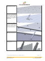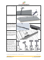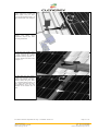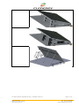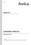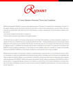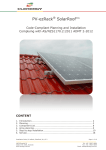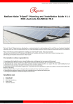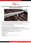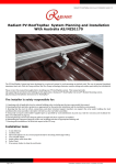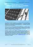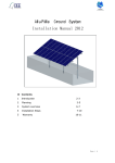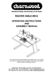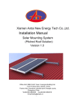
1
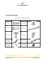
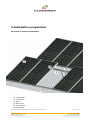
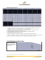
SolarRoof Adjustable Tilt Legs Code-Compliant Planning and Installation with Australia AS/NZS1170 Clenergy SolarRoof Adjustable Tilt Legs have been developed as a universal PV modules mounting system for the flat/tilt roof. The innovative and patented aluminum base rails, the Z modules and the rail extension technology eliminate the need for onsite cutting and enables quick and easy field PV module installations. Please read the installation instructions carefully before beginning installation. First familiarize yourself with the system components. During installation, and especially when working on the roof, be sure to observe the appropriate safety regulations and please pay attention to the relevant regulations of your local region. Please check the current version of the installation manual under www.clenergy.com.au. PV-ezRack SolarRoof Adjustable Tilt Legs - Installation Guide V2.0 18/20 Duerdin St Clayton VIC 3168, Australia www.clenergy.com.au Page 1 of 14 Tel: +61 3 9017 6688 Fax: +61 3 9017 6668 Email: [email protected] The installer is solely responsible for: • Complying with all applicable local or national building codes, including any that may supersede this manual; • Ensuring that ezRack and other products are appropriate for the particular installation and the installation environment; • Ensuring that the roof, its rafters, connections, and other structural support members can support the array under building live load conditions (this total assembly is hereafter referred to as the roof rafter assembly); • Using only ezRack parts and installer-supplied parts as specified by ezRack (substitution of parts may void the warranty and invalidate the letter of certification on page 2); • Ensuring that lag screws have adequate pullout strength and shear capacities as installed; • Maintaining the waterproof integrity of the roof, including selection of appropriate flashing; • Ensuring safe installation of all electrical aspects of the PV array. PV-ezRack SolarRoof Adjustable Tilt Legs - Installation Guide V2.0 18/20 Duerdin St Clayton VIC 3168, Australia www.clenergy.com.au Page 2 of 14 Tel: +61 3 9017 6688 Fax: +61 3 9017 6668 Email: [email protected] 1. Planning This document is designed to support for installations using SolarRoof™ Adjustable Tilt Legs, manufactured by Clenergy Co. Ltd. Follow the six steps below and the installation instructions section to install Clenergy Adjustable Tilt Legs in compliance with the AS/NZS1170. Before proceeding, note the following: This document addresses only wind loads on the assumption that wind produces the maximum load factor affecting an installation. Verify that other local factors, such as snow loads and earth quake effects, do not exceed the wind loads. Give precedence to any factor that does. Wind loads are considered to act on the entire projected area, or may be perpendicular to any surface. The roof on which the SolarRoof™ will be installed must have the capacity to resist the combined Design Dead Load and Live Load per footing. Installation tools 6 mm and 4mm Allen key Cordless drill Open-end spanner set 9, 10, 17, 19 mm (required only for mounting with Nut) Torx-30 (AW 30) bit Power Cord PV-ezRack SolarRoof Adjustable Tilt Legs - Installation Guide V2.0 18/20 Duerdin St Clayton VIC 3168, Australia www.clenergy.com.au Page 3 of 14 Tel: +61 3 9017 6688 Fax: +61 3 9017 6668 Email: [email protected] 1. Determine the wind region of your installation site Region Definition: Wind regions are pre defined for all of Australia by Australian Standard 1170. The Wind Region has nothing to do with surrounding topography or buildings. • • • • Most of Australia is designated Region A which indicates a Regional Ultimate Basic Wind Velocity of 45msec. Some areas are designated Region B (57msec). Local authorities will advise if this applies in your area. Region C areas (66msec) are generally refered to as Cyclonic and are generally limited to northern coastal areas. Most Region C zones end 100km inland. Region D (80msec) Australia's worst Cyclonic Region between Carnarvon and Pardoo in Western Australia. PV-ezRack SolarRoof Adjustable Tilt Legs - Installation Guide V2.0 18/20 Duerdin St Clayton VIC 3168, Australia www.clenergy.com.au Page 4 of 14 Tel: +61 3 9017 6688 Fax: +61 3 9017 6668 Email: [email protected] 2. Determine the height of the installation site This document provides sufficient information for SolarRoof™ Adjustable Tilt Legs system installation height less than 20 meters. If your installation site is more than 20 meters in height, please contact Clenergy to obtain engineering data to support your installation. 3. Determine the Maximum Rail Support Spacing Please use the following table to determine the base rail support spacing for sheet metal roof installations. Max PV panel length: 2150mm. Max panel weight: 15 kg/m2 a) 10 to 15 degree Installation Height Region A (mm) Region B (mm) Region C (mm) Region D (mm) Max Area of 1 panel 3.0m2 2.5m2 2.0m2 1.5m2 up to 5 m up to 10 m up to 15m 1560 1420 1345 975 890 845 660 600 570 405 up to 20 m 1275 800 540 330 370 350 b) 15 to 30 degree and 30 to 60 degree Installation Height Region A (mm) Region B (mm) Region C (mm) Region D (mm) Max Area of 1 panel 3.0m2 2.5m2 2.0m2 1.5m2 up to 5 m up to 10 m up to 15m 1360 1240 1175 890 810 770 605 550 520 370 up to 20 m 1115 725 495 305 PV-ezRack SolarRoof Adjustable Tilt Legs - Installation Guide V2.0 18/20 Duerdin St Clayton VIC 3168, Australia www.clenergy.com.au 340 320 Page 5 of 14 Tel: +61 3 9017 6688 Fax: +61 3 9017 6668 Email: [email protected] Please consult Clenergy for installing PV modules with a greater length than 2150mm or heavier than 15 kg/m2. Each Foot should be fixed to the purlins under using at least two 12g (6mm) screw through sheet metal roofs with gasket. The above spacing applies for fixing through thin sheet purlins (greater than 0.75mm thickness) or a minimum embedment of 50mm into timber purlins. For 35mm min embedment in to timber or fixing in to 0.55mm thickness sheet purlins the maximum panel length should be reduced to 1700mm and maximum spacing reduced by 20%. Please note that the screws provided with our products are designed for mounting in to wooden structures. 4. Verify acceptable Rail End Overhang Rail End Overhang must equal 50 percent or less of foot spacing. Thus, if foot spacing is 1200mm, the Rail End Over hang can be up to 600mm. In this case, two feet can support a rail of as much as 2400mm (1200mm between the feet and 600mm of overhang at each end). 5. Determine installation slope Clenergy SolarRoof™ Adjustable Tilt Legs system can be used for roof slope from -30 to 30 degree. 6. Determine Roof Installation Roof Areas Clenergy SolarRoof Adjustable Tilt Legs can be installed using those spacing everywhere on the roof. PV-ezRack SolarRoof Adjustable Tilt Legs - Installation Guide V2.0 18/20 Duerdin St Clayton VIC 3168, Australia www.clenergy.com.au Page 6 of 14 Tel: +61 3 9017 6688 Fax: +61 3 9017 6668 Email: [email protected] 2. Components list Overview of system components Part name Picture Part name ezRack Rail Front Foot Splice Back Legs Inter Clamp End Clamp M8*25 Hex head bolt Pan-head Wood Screw 6*90 Hex head bolt M8*55 Set Screw M10*10 PV-ezRack SolarRoof Adjustable Tilt Legs - Installation Guide V2.0 18/20 Duerdin St Clayton VIC 3168, Australia www.clenergy.com.au Picture Page 7 of 14 Tel: +61 3 9017 6688 Fax: +61 3 9017 6668 Email: [email protected] 3. Installation preparation Overview of system components 1. 2. 3. 4. 5. 6. ezRack Rail Front Foot Splice Back Legs Inter Clamp End Clamp PV-ezRack SolarRoof Adjustable Tilt Legs - Installation Guide V2.0 18/20 Duerdin St Clayton VIC 3168, Australia www.clenergy.com.au Page 8 of 14 Tel: +61 3 9017 6688 Fax: +61 3 9017 6668 Email: [email protected] Planning the module area 1. Number of modules in the vertical direction x module height (please check also the installation manual of the manufacturer of the solar module) 2. Number of modules in horizontal direction x (module width + 17 mm) + 32 mm 3. Horizontal spacing of the Fix Foot up to 2.0 m* 4. Vertical spacing of the Fix Foot = approx. 1⁄2 to 3⁄4 of module height 5. Distance between the modules: 17mm 6. Distance between 2 strings needs to be calculated based on the location * Caution: Installations that are exposed to the wind or are located on the edge or corners of the roof may make it necessary to leave smaller spaces between modules. 4. Installation Instruction 1. Determine the positions of the Front Foot according to your plans. Shim the Front Foot with rubber , Fix the Front Foot to the rafter using two 6 x 65 mm wood screws PV-ezRack SolarRoof Adjustable Tilt Legs - Installation Guide V2.0 18/20 Duerdin St Clayton VIC 3168, Australia www.clenergy.com.au Page 9 of 14 Tel: +61 3 9017 6688 Fax: +61 3 9017 6668 Email: [email protected] 2. Fix the Front Foot to the rafter according to your plans. 3. Put the U Bracket into the Front foot, It is recommended to mount them just a bit fasten, so it could be adjusted in the mounting and fasten completely. Fix the U Bracket with the Rail by Z module use M8X25mm bolt 4. Base rail installation, Position the first frame rails for each row and fasten them temporarily to the roof cladding using a cord. Tighten the Allen bolts on the Z modules that are used to fasten the Front Foot 5. Install the Back legs, put the Back Legs into the fix foot and fasten them by M8X55mm bolt. 6. Adjsut the length using 4mm Allen key to fix them by one set screw M8*10mm PV-ezRack SolarRoof Adjustable Tilt Legs - Installation Guide V2.0 18/20 Duerdin St Clayton VIC 3168, Australia www.clenergy.com.au Page 10 of 14 Tel: +61 3 9017 6688 Fax: +61 3 9017 6668 Email: [email protected] 7. Fix the L Bracket with the Leg tube by using M8X55mm bolt. 8. Base rail installation, Fix the L Bracket with the base rail by z module use M8x25mm bolt 9. To connect multiple rails together, slide the splices on the rear side of the preassembled rails halfway to the side. Fasten the first M8 Allen bolt firmly using the Allen key. Now slide the next rail segment into the splice. 10. Tighten the second M8 Allen bolt using the Allen key. The connection is finished. An expansion gap at the rail joints is recommended. For this purpose, leave a gap about the same width as a finger between the rail joints and then loosely tighten the M8 allen bolt. 11. For easy use of the Z module, you must make sure that the thread of the screws does not project through the lower side of the Z Module (max. flush). Position the Z Module in the rail channel and fasten it loosely with 2 to 3 turns of the screw. The screws can still be freely moved in the rail channel. Slide the screws to their final position in connection with the inter-module clamp, module end clamp or roof hooks/hanger bolts and fasten firmly (recommended torque is 8 Nm). PV-ezRack SolarRoof Adjustable Tilt Legs - Installation Guide V2.0 18/20 Duerdin St Clayton VIC 3168, Australia www.clenergy.com.au Page 11 of 14 Tel: +61 3 9017 6688 Fax: +61 3 9017 6668 Email: [email protected] 12. Slide the module end clamp tightly against the module and fasten tightly using the Allen bolt (recommended torque is 8 Nm). Please take note of Figure 11. 13. Cross-section through the module end clamp when installation step12 has been correctly performed. 14. Fix the inter-module clamp into the rails from above, place it firmly against the module and fasten loosely (approx. 2 3 turns). Please also take note of Figure 11. 15. Now slide the next module against the previously installed module and tighten the intermodule clamp using the Allen key (recommended torque is 8 Nm). Take care that the antislip protection sits in the rail channel of the lowest row of rails. PV-ezRack SolarRoof Adjustable Tilt Legs - Installation Guide V2.0 18/20 Duerdin St Clayton VIC 3168, Australia www.clenergy.com.au Page 12 of 14 Tel: +61 3 9017 6688 Fax: +61 3 9017 6668 Email: [email protected] 10 to 15 degree 15 to 30 degree 30 to 60 degree PV-ezRack SolarRoof Adjustable Tilt Legs - Installation Guide V2.0 18/20 Duerdin St Clayton VIC 3168, Australia www.clenergy.com.au Page 13 of 14 Tel: +61 3 9017 6688 Fax: +61 3 9017 6668 Email: [email protected] 10 year limited Product Warranty, 5 year limited Finish Warranty Clenergy co. Ltd warrants to the original purchaser (“Purchaser”) of product(s) that it manufactures (“Product”) at the original installation site that the Product shall be free from defects in material and workmanship for a period of ten (10) years, except for the anodised finish, which finish shall be free from visible peeling, or cracking or chalking under normal atmospheric conditions for a period of five (5) years, from the earlier of 1) the date the installation of the Product is completed, or 2) 30 days after the purchase of the Product by the original Purchaser (“Finish Warranty”). The Finish Warranty does not apply to any foreign residue deposited on the finish. All installations in corrosive atmospheric conditions are excluded. The Finish Warranty is VOID if the practices specified by AAMA 609 & 610-02 – “Cleaning andMaintenance for Architecturally Finished Aluminum” (www.aamanet.org) are not followed by Purchaser. This Warranty does not cover damage to the Product that occurs during its shipment, storage, or installation. This Warranty shall be VOID if installation of the Product is not performed in accordance with Clenergy’s written installation instructions, or if the Product has been modified, repaired, or reworked in a manner not previously authorized by Clenergy IN WRITING, or if the Product is installed in an environment for which it was not designed. Clenergy shall not be liable for consequential, contingent or incidental damages arising out of the use of the Product by Purchaser under any circumstances. If within the specified Warranty periods the Product shall be reasonably proven to be defective, then Clenergy shall repair or replace the defective Product, or any part thereof, in Clenergy’s sole discretion. Such repair or replacement shall completely satisfy and discharge all of Clenergy’s liability with respect to this limited Warranty. Under no circumstances shall Clenergy be liable for special, indirect or consequential damages arising out of or related to use by Purchaser of the Product. Manufacturers of related items, such as PV modules and flashings, may provide written warranties of their own. Clenergy’s limited Warranty covers only its Product, and not any related items. PV-ezRack SolarRoof Adjustable Tilt Legs - Installation Guide V2.0 18/20 Duerdin St Clayton VIC 3168, Australia www.clenergy.com.au Page 14 of 14 Tel: +61 3 9017 6688 Fax: +61 3 9017 6668 Email: [email protected]