1
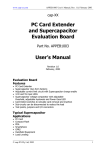
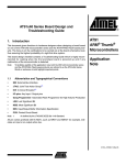
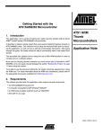
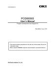
AT91SAM-ICE
..............................................................................................
User Guide
Table of Contents
Section 1
Introduction ........................................................................................... 1-1
1.1
1.2
Overview ...................................................................................................1-1
Requirements............................................................................................1-2
Section 2
Hardware .............................................................................................. 2-1
2.1
2.2
JTAG Connector .......................................................................................2-1
Debugging Multiple ARM® Cores with SAM-ICE ......................................2-2
Section 3
Setup .................................................................................................... 3-1
3.1
3.2
3.3
3.4
Installing the USB Driver ...........................................................................3-1
Debug Installation .....................................................................................3-5
Connecting the Target System .................................................................3-5
Problems ...................................................................................................3-5
Section 4
SAM-ICE Related Software .................................................................. 4-1
4.1
4.2
Overview ...................................................................................................4-1
Free Software ...........................................................................................4-1
Section 5
Frequently Asked Questions................................................................. 5-1
5.1
FAQs .........................................................................................................5-1
Section 6
Support ................................................................................................. 6-1
6.1
6.2
Troubleshooting ........................................................................................6-1
Contacting Support ...................................................................................6-2
Section 7
Glossary................................................................................................ 7-1
7.1
Terminology ..............................................................................................7-1
Section 8
Errata .................................................................................................... 8-1
8.1
AT91SAM-ICE User Guide
Reset Problem on the SAM-ICE V5.1 .......................................................8-1
i
6206A–ATARM–24-Nov-05
ii
6206A–ATARM–24-Nov-05
AT91SAM-ICE User Guide
Section 1
Introduction
SAM-ICE is a JTAG emulator designed for Atmel® AT91 ARM® cores. It connects via
USB to a PC running Microsoft Windows2000 or XP. SAM-ICE has a built-in 20-pin
JTAG connector, which is compatible with the standard 20-pin connector defined by
ARM®.
1.1
Overview
1.1.1
Features of SAM-ICE ! Any Atmel AT91 ARM7™/ARM9™ core supported, including Thumb® mode
! Seamless integration into the IAR® Workbench
! No power supply required, powered through USB
! Maximum JTAG speed 8 MHz
! Auto speed recognition
! All JTAG signals can be monitored
! Support for multiple devices
! Fully plug and play compatible
! Standard 20-pin JTAG connector
! Wide target voltage range: 1.2V to 3.3V
! USB and 20-pin ribbon cable included
! Real-time memory viewer (J-Mem) included
! SAM-ICE TCP/IP server included, can use SAM-ICE via TCP/IP networks
! RDI server available, can use SAM-ICE with RDI compliant software
1.1.2
Specification
Table 1-1. SAM-ICE Specification
Parameter
AT91SAM-ICE User Guide
Power Supply
USB powered < 50mA
USB Interface
USB 2.0, full speed
Target Interface
JTAG 20-pin
Serial Transfer Rate between SAM-ICE and Target
Up to 8 MHz
Supported Target Voltage
1.2V to 3.3V
1-1
6206A–ATARM–24-Nov-05
Introduction
Table 1-1. SAM-ICE Specification
Parameter
Operating Temperature
+5°C to +60°C
Storage Temperature
-20°C to +65 °C
Relative Humidity (non-condensing)
< 90% rH
Size (without cables)
100 mm x 53 mm x 27 mm
Weight (without cables)
70 g
Electromagnetic Compatibility (EMC)
EN 55022, EN 55024
Supported OS
Microsoft Windows2000/XP
1.2
Requirements
1.2.1
Host System
In order to use SAM-ICE, a host system running Windows2000 or WindowsXP with the
SAM-ICE custom USB driver is required.
1.2.2
Target System
An Atmel AT91 ARM7 or ARM9 target system is required. The system should have a
20-pin connector as defined by ARM Ltd. The individual pins are described in “JTAG
Connector” on page 10.
1-2
6206A–ATARM–24-Nov-05
AT91SAM-ICE User Guide
Section 2
Hardware
2.1
JTAG Connector
A SAM-ICE connector is a 20-way Insulation Displacement Connector (IDC) keyed box
header (2.54 mm male) that mates with IDC sockets mounted on a ribbon cable.
2.1.1
Pinout
Table 2-1 lists the SAM-ICE JTAG pinout.
Table 2-1. Pinout
Pin
Signal
Type
Description
1
VTref
Input
This is the target reference voltage.
It is used to check if the target has power, to create the logic-level reference for the input
comparators and controls the output logic levels to the target. It is normally fed from Vdd on the
target board and must not have a series resistor.
2
Vsupply
NC
3
nTRST
Output
4
GND
-
5
TDI
Output
6
GND
-
7
TMS
Output
8
GND
-
9
TCK
Output
10
GND
-
11
RTCK
NC
AT91SAM-ICE User Guide
This pin is not connected in SAM-ICE.
It is reserved for compatibility with other equipment.
Connect to Vdd or leave open in target system.
JTAG Reset. Output from SAM-ICE to the Reset signal on the target JTAG port.
Typically connected to nTRST on the target CPU. This pin is normally pulled HIGH on the target
to avoid unintentional resets when there is no connection.
Common ground
JTAG data input of target CPU.
It is recommended that this pin is pulled to a defined state on the target board. Typically
connected to TDI on target CPU.
Common ground
JTAG mode set input of target CPU.
This pin should be pulled up on the target.
Typically connected to TMS on target CPU.
Common ground
JTAG clock signal to target CPU.
It is recommended that this pin is pulled to a defined state on the target board. Typically
connected to TCK on target CPU.
Common ground
This pin is not connected in SAM-ICE.
It is reserved for compatibility with other equipment to be used as return test clock signal from
target JTAG port. Connect to RTCK if available, otherwise to GND.
2-1
6206A–ATARM–24-Nov-05
Hardware
Table 2-1. Pinout
Pin
Signal
Type
12
GND
-
13
TDO
Input
14
GND
-
15
RESET
I/O
16
GND
-
17
-
NC
18
GND
-
19
-
NC
20
GND
-
2.2
Debugging
Multiple ARM®
Cores with
SAM-ICE
Description
Common ground
JTAG data output from target CPU.
Typically connected to TDO on target CPU.
Common ground
Target CPU reset signal
Common ground
This pin is not connected in SAM-ICE.
Common ground
This pin is not connected in SAM-ICE.
Common ground
SAM-ICE can handle mulitcore debugging. In this case, multiple ARM chips are connected to the same JTAG connector as shown in Figure 2-1.
Figure 2-1. Multi-core Connections
TDI
TDO
Device 0
TCK
TDI
TMS
TDI
TDO
Device 1
TRST
TDO
JTAG
2-2
6206A–ATARM–24-Nov-05
AT91SAM-ICE User Guide
Section 3
Setup
3.1
Installing the
USB Driver
When your SAM-ICE is plugged into the computer's USB port, or when the computer is
first powered-on after connecting SAM-ICE, Windows® detects the new hardware.
The wizard starts the installation of the driver. First, select the "Search for a suitable driver for my device (recommended)" option, then click on the
"Next >" button.
AT91SAM-ICE User Guide
3-1
6206A–ATARM–24-Nov-05
Setup
In the next step, you need to select the "Specify a location" option, and click on
the "Next >" button.
Copy the driver available on the DVD-ROM to your location.
The wizard asks you to specify the location of the correct driver files for the new device.
Use the directory navigator to select “D:\tools\driver\usb\jlinkarm” (or your
chosen location) and confirm with a click on the "Next >" button.
3-2
6206A–ATARM–24-Nov-05
AT91SAM-ICE User Guide
Setup
The wizard confirms your choice and starts to copy, when you click on the "OK"
button.
At this point, the installation is complete. Click on the "Finish" button to dismiss the
installation.
3.1.1
Verifying Correct
Driver Installation
AT91SAM-ICE User Guide
To verify the correct installation of the driver, disconnect and reconnect SAM-ICE to the
USB port. During the enumeration process which takes about 2 seconds, the LED on
SAM-ICE is flashing. After successful enumeration, the LED stays on permanently.
3-3
6206A–ATARM–24-Nov-05
Setup
Start the provided sample application JLink.exe. JLink.exe should display the build
date of the SAM-ICE firmware, the serial number, a target voltage of 0.000V if a target is
not connected to SAM-ICE and the speed selection. See the screenshot below.
In addition to this you may verify the driver installation by consulting the Windows®
device manager. If the driver is installed and your SAM-ICE is connected to your computer, the device manager should list the J-Link driver as a node below "Universal Serial
Bus controllers" as shown in the following screenshot:
A right-click on the driver opens a context menu which contains the item “Properties”. If
you select this item, a new dialog is opened and should report: “This device is working
properly”.
3-4
6206A–ATARM–24-Nov-05
AT91SAM-ICE User Guide
Setup
3.2
Debug
Installation
The SAM-ICE RDI software is an RDI interface for SAM-ICE. It makes it possible to use
SAM-ICE with any RDI compliant debugger.
The main part of the software is an RDI compliant DLL, which needs to be selected in
the debugger.
Supported configurations are described on the AT91 DVD-ROM. For additional information on debug, refer to the SAM-ICE "Getting started" bar menu.
3.3
Connecting the
Target System
3.3.1
Power-on Sequence
SAM-ICE must be powered on before connecting it to the target device. First, connect
SAM-ICE to the host system via the USB and then connect SAM-ICE to the target
device via JTAG. Power-on the device after you have connected SAM-ICE to it.
3.3.2
Verifying Target
Device Connection
If the USB driver is working properly and your SAM-ICE is connected to the host system,
you may connect SAM-ICE to your target hardware. Then start JLink.exe again; it
should now display the same SAM-ICE related information as above. In addition, it
should report that it found a JTAG target and the target core ID. The screenshot below
shows the output of JLink.exe. As can be seen, it reports a SAM-ICE with one JTAG
device connected.
3.4
Problems
For help with any of the steps described above, refer to Section 6.1 for troubleshooting
tips.
AT91SAM-ICE User Guide
3-5
6206A–ATARM–24-Nov-05
Setup
3-6
6206A–ATARM–24-Nov-05
AT91SAM-ICE User Guide
Section 4
SAM-ICE Related Software
4.1
Overview
Table 4-1. Available Software Packages
4.2
Free Software
Software
Description
JLink.exe
Free Command line tool with basic functionality for target
analysis.
SAM-ICE TCP/IP Server
Free utility which provides the possibility to use SAM-ICE
remotely via TCP/IP.
J-Mem memory viewer
Free target memory viewer. Shows the memory content of a
running target and allows editing as well.
SAM-ICE ARM® Flash DLL
An enhanced version of the JLinkARM.DLL, which contains
additional API functions for Flash programming.
RDI support
Provides Remote Debug Interface (RDI) support.
Free software related to SAM-ICE ships with SAM-ICE and may also be downloaded
from the web site:
http://www.segger.com
No additional license is required to use this software.
4.2.1
JLink.exe
(Command Line
Tool)
JLink.exe is a tool, that can be used to verify proper installation of the USB driver and to
verify the connection to the ARM® chip, as well as for simple analysis of the target system. It permits some simple commands, such as memory dump, halt, step, go and IDcheck, as well as some more in-depths analysis of the the state of the ARM® core and
the ICE breaker module.
4.2.2
SAM-ICE TCP/IP
Server (Remote
SAM-ICE Use)
The SAM-ICE TCP/IP server allows using SAM-ICE remotely via TCP/IP. This enables
you to connect to and fully use a SAM-ICE from another computer. Performance is just
slightly (about 10%) lower than with direct USB connection.
AT91SAM-ICE User Guide
4-1
6206A–ATARM–24-Nov-05
SAM-ICE Related Software
4.2.3
J-Mem Memory
Viewer
4-2
6206A–ATARM–24-Nov-05
J-Mem displays memory contents of ARM® systems and allows modifications of RAM
and SFRs (Special function registers) while the target is running. This makes it possible
to look into the memory of an ARM® chip at run time; RAM can be modified and SFRs
can be written. The type of acces for both read and write access can be selected to be
8/16/32 bits. This is an efficient means for modifying SFRs, in particular because it
writes the SFR only after the complete value has been entered.
AT91SAM-ICE User Guide
Section 5
Frequently Asked Questions
5.1
FAQs
! Which CPUs are supported?
– SAM-ICE works exclusively
microcontroller cores.
with Atmel AT91 ARM7™/ARM9™-based
! What is the maximum JTAG speed supported by SAM-ICE?
– The maximum supported JTAG speed is 8 MHz.
! Can I access individual ICE registers via SAM-ICE?
– Yes, you can access all individual ICE registers via SAM-ICE.
! Can SAM-ICE read back the status of the JTAG pins?
– Yes, the status of all pins can be read. This includes the outputs of SAM-ICE
as well as the supply voltage and can be useful to detect hardware problems
on the target system.
! Does SAM-ICE support the embedded trace macro (ETM)?
– No. ETM requires another connection to the ARM® chip and a CPU with builtin ETM.
AT91SAM-ICE User Guide
5-1
6206A–ATARM–24-Nov-05
Frequently Asked Questions
5-2
6206A–ATARM–24-Nov-05
AT91SAM-ICE User Guide
Section 6
Support
6.1
Troubleshooting
6.1.1
General Procedure
If you experience problems with a SAM-ICE, follow the steps below to solve these
problems:
1. Close all running applications on your host system.
2. Disconnect the SAM-ICE device from USB.
3. Power-off target.
4. Re-connect SAM-ICE to host system (attach USB cable).
5. Power-on target.
6. Try your target application again. It the problem disappears, you are done; otherwise continue.
7. Close all applications running on your host system again.
8. Disconnect the SAM-ICE device from USB.
9. Power-off target.
10. Re-connect SAM-ICE to host system (attach USB cable).
11. Power-on target.
12. Start JLink.exe.
13. If JLink.exe reports the SAM-ICE serial number and the target processor’s
core ID, the SAM-ICE is working properly and cannot be the cause of your
problem.
14. If JLink.exe is unable to read the target processor’s core ID, you should analyze the communication between your target and SAM-ICE with a logic analyzer
or oscilloscope.
15. If your problem persists and you own an original SAM-ICE (not an OEM version),
see Section 6.2.
6.1.2
Typical Problem
Scenarios
6.1.2.1
SAM-ICE LED is off
! Meaning:
– The USB connection does not work.
! Corrective action:
AT91SAM-ICE User Guide
6-1
6206A–ATARM–24-Nov-05
Support
– Check the USB connection. Try to re-initialize SAM-ICE by disconnecting and
reconnecting it. Make sure that the connectors are firmly attached. Check the
cable connections on your SAM-ICE and the computer. If this does not solve
the problem, please check if your cable is defective. If the USB cable is ok, try
a different PC.
6.1.2.2
SAM-ICE LED is
flashing at a high
frequency
! Meaning:
– SAM-ICE cannot be enumerated by the USB controller.
! Most likely causes:
– a.) Another program is already using SAM-ICE.
– b.) The SAM-ICE USB driver does not work correctly.
! Corrective action:
– a.) Close all running applications and try to reinitialize SAM-ICE by
disconnecting and reconnecting it.
– b.) If the LED blinks permanently, check the correct installation of the SAMICE USB driver. Deinstall and reinstall the driver as shown in Section 3.
6.1.2.3
SAM-ICE does not
get any connection
to the target
! Most likely causes:
– a.) The JTAG cable is defective
– b.) The target hardware is defective
! Corrective action:
– Follow the steps described in Section 6.1.1.
6.2
Contacting
Support
Before contacting support, assure that you have tried to solve your problem by following
the steps outlined in section Section 6.1.1. You may also try your SAM-ICE with another
PC and, if possible, with another target system to see if it works there. If the device functions correctly, the USB setup on the original machine or your target hardware is the
source of the problem, not SAM-ICE.
Make sure that you have the following information available for the support team:
! A detailed description of the problem
! SAM-ICE serial number
! Output of JLink.exe if available
! Your findings on the signal analysis
! Information about your target hardware (processor, board etc.)
6-2
6206A–ATARM–24-Nov-05
AT91SAM-ICE User Guide
Section 7
Glossary
7.1
Terminology
Adaptive clocking
A technique in which a clock signal is sent out by Multi-ICE and it waits for the returned
clock before generating the next clock pulse. The technique allows the Multi-ICE interface unit to adapt to differing signal drive capabilities and differing cable lengths.
Application Program
Interface
A specification of a set of procedures, functions, data structures, and constants that are
used to interface two or more software components together.
Big-endian
Memory organization where the least significant byte of a word is at a higher address
than the most significant byte. See Little-endian.
Cache cleaning
The process of writing dirty data in a cache to main memory.
Coprocessor
An additional processor that is used for certain operations, for example, for floating-point
math calculations, signal processing, or memory management.
Dirty data
When referring to a processor data cache, data that has been written to the cache but
has not been written to main memory. Only write-back caches can have dirty data,
because a write-through cache writes data to the cache and to main memory simultaneously. The process of writing dirty data to main memory is called cache cleaning.
Dynamic Linked
Library (DLL)
A collection of programs, any of which can be called when needed by an executing program. A small program that helps a larger program communicate with a device such as
a printer or keyboard is often packaged as a DLL.
EmbeddedICE™
The additional hardware provided by debuggable ARM® processors to aid debugging.
Halfword
A 16-bit unit of information. Contents are taken as being an unsigned integer unless otherwise stated.
Host
A computer which provides data and other services to another computer. Especially, a
computer providing debugging services to a target being debugged.
ICache
Instruction cache.
ICE Extension Unit
A hardware extension to the EmbeddedICE logic that provides more breakpoint units.
ID
Identifier.
IEEE 1149.1
The IEEE Standard which defines TAP. Commonly (but incorrectly) referred to as JTAG.
AT91SAM-ICE User Guide
7-1
6206A–ATARM–24-Nov-05
Glossary
Image
An executable file that has been loaded onto a processor for execution.
In-Circuit Emulator
(ICE)
A device enabling access to and modification of the signals of a circuit while that circuit
is operating.
Instruction Register
When referring to a TAP controller, a register that controls the operation of the TAP.
IR
See Instruction Register.
Joint Test Action
Group (JTAG)
The name of the standards group which created the IEEE 1149.1 specification.
Little-endian
Memory organization where the least significant byte of a word is at a lower address
than the most significant byte. See also Big-endian.
Memory
Management Unit
(MMU)
Hardware that controls caches and access permissions to blocks of memory, and translates virtual to physical addresses.
Multi-ICE®
Multi-processor EmbeddedICE interface. ARM® registered trademark.
nSRST
Abbreviation of System Reset. The electronic signal which causes the target system
other than the TAP controller to be reset. This signal is known as nSYSRST in some
other manuals. See also nTRST.
nTRST
Abbreviation of TAP Reset. The electronic signal that causes the target system TAP
controller to be reset. This signal is known as nICERST in some other manuals. See
also nSRST.
Open collector
A signal that may be actively driven LOW by one or more drivers, and is otherwise passively pulled HIGH. Also known as a “wired AND” signal.
Processor Core
The part of a microprocessor that reads instructions from memory and executes them,
including the instruction fetch unit, arithmetic and logic unit and the register bank. It
excludes optional coprocessors, caches, and the memory management unit.
Program Status
Register (PSR)
Contains some information about the current program and some information about the
current processor. Often, therefore, also referred to as Processor Status Register.
Is also referred to as Current PSR (CPSR), to emphasize the distinction between it and
the Saved PSR (SPSR). The SPSR holds the value the PSR had when the current function was called, and which will be restored when control is returned.
Remapping
Changing the address of physical memory or devices after the application has started
executing. This is typically done to allow RAM to replace ROM once the initialization has
been done.
Remote Debug
Interface (RDI)
RDI is an open ARM® standard procedural interface between a debugger and the debug
agent. The widest possible adoption of this standard is encouraged.
RTCK
Returned TCK. The signal which enables Adaptive Clocking.
RTOS
Real Time Operating System.
Scan Chain
A group of one or more registers from one or more TAP controllers connected between
TDI and TDO, through which test data is shifted.
Semihosting
A mechanism whereby the target communicates I/O requests made in the application
code to the host system, rather than attempting to support the I/O itself.
SWI
Software Interrupt. An instruction that causes the processor to call a programer-specified subroutine. Used by ARM® to handle semihosting.
7-2
6206A–ATARM–24-Nov-05
AT91SAM-ICE User Guide
Glossary
TAP Controller
Logic on a device which allows access to some or all of that device for test purposes.
The circuit functionality is defined in IEEE1149.1.
Target
The actual processor (real silicon or simulated) on which the application program is
running.
TCK
The electronic clock signal which times data on the TAP data lines TMS, TDI, and TDO.
TDI
The electronic signal input to a TAP controller from the data source (upstream). Usually
this is seen connecting the Multi-ICE Interface Unit to the first TAP controller.
TDO
The electronic signal output from a TAP controller to the data sink (downstream). Usually this is seen connecting the last TAP controller to the Multi-ICE Interface Unit.
Test Access Port
(TAP)
The port used to access a device's TAP Controller. Comprises TCK, TMS, TDI, TDO
and nTRST (optional).
Transistor-transistor A type of logic design in which two bipolar transistors drive the logic output to one or
Logic (TTL)
zero. LSI and VLSI logic often used TTL with HIGH logic level approaching +5V and
LOW approaching 0V.
Watchpoint
A location within the image that will be monitored and that will cause execution to stop
when it changes.
Word
A 32-bit unit of information. Contents are taken as being an unsigned integer unless otherwise stated.
AT91SAM-ICE User Guide
7-3
6206A–ATARM–24-Nov-05
Glossary
7-4
6206A–ATARM–24-Nov-05
AT91SAM-ICE User Guide
Section 8
Errata
8.1
Reset Problem
on the SAM-ICE
V5.1
In certain cases, the reset signal generated by the AT91 target may be inoperative due
to the fact that the SAM-ICE reset output (JTAG connector pin 15) is a push-pull stage
with a 100 Ohm serial resistor.
Workaround: Two workarounds are possible:
! Replace R19 by a Schottky diode with the same resistor footprint (e.g. BAT54J).
or
! Remove the resistor.
This problem has been resolved in SAM-ICE V5.2.
R19
AT91SAM-ICE User Guide
8-1
6206A–ATARM–24-Nov-05
Errata
8-2
6206A–ATARM–24-Nov-05
AT91SAM-ICE User Guide
Atmel Corporation
2325 Orchard Parkway
San Jose, CA 95131, USA
Tel: 1(408) 441-0311
Fax: 1(408) 487-2600
Regional Headquarters
Europe
Atmel Sarl
Route des Arsenaux 41
Case Postale 80
CH-1705 Fribourg
Switzerland
Tel: (41) 26-426-5555
Fax: (41) 26-426-5500
Asia
Room 1219
Chinachem Golden Plaza
77 Mody Road Tsimshatsui
East Kowloon
Hong Kong
Tel: (852) 2721-9778
Fax: (852) 2722-1369
Japan
9F, Tonetsu Shinkawa Bldg.
1-24-8 Shinkawa
Chuo-ku, Tokyo 104-0033
Japan
Tel: (81) 3-3523-3551
Fax: (81) 3-3523-7581
Atmel Operations
Memory
2325 Orchard Parkway
San Jose, CA 95131, USA
Tel: 1(408) 441-0311
Fax: 1(408) 436-4314
RF/Automotive
Theresienstrasse 2
Postfach 3535
74025 Heilbronn, Germany
Tel: (49) 71-31-67-0
Fax: (49) 71-31-67-2340
Microcontrollers
2325 Orchard Parkway
San Jose, CA 95131, USA
Tel: 1(408) 441-0311
Fax: 1(408) 436-4314
La Chantrerie
BP 70602
44306 Nantes Cedex 3, France
Tel: (33) 2-40-18-18-18
Fax: (33) 2-40-18-19-60
ASIC/ASSP/Smart Cards
1150 East Cheyenne Mtn. Blvd.
Colorado Springs, CO 80906, USA
Tel: 1(719) 576-3300
Fax: 1(719) 540-1759
Biometrics/Imaging/Hi-Rel MPU/
High Speed Converters/RF Datacom
Avenue de Rochepleine
BP 123
38521 Saint-Egreve Cedex, France
Tel: (33) 4-76-58-30-00
Fax: (33) 4-76-58-34-80
Zone Industrielle
13106 Rousset Cedex, France
Tel: (33) 4-42-53-60-00
Fax: (33) 4-42-53-60-01
1150 East Cheyenne Mtn. Blvd.
Colorado Springs, CO 80906, USA
Tel: 1(719) 576-3300
Fax: 1(719) 540-1759
Scottish Enterprise Technology Park
Maxwell Building
East Kilbride G75 0QR, Scotland
Tel: (44) 1355-803-000
Fax: (44) 1355-242-743
Literature Requests
www.atmel.com/literature
Disclaimer: The information in this document is provided in connection with Atmel products. No license, express or implied, by estoppel or otherwise, to any
intellectual property right is granted by this document or in connection with the sale of Atmel products. EXCEPT AS SET FORTH IN ATMEL’S TERMS AND CONDITIONS OF SALE LOCATED ON ATMEL’S WEB SITE, ATMEL ASSUMES NO LIABILITY WHATSOEVER AND DISCLAIMS ANY EXPRESS, IMPLIED OR STATUTORY
WARRANTY RELATING TO ITS PRODUCTS INCLUDING, BUT NOT LIMITED TO, THE IMPLIED WARRANTY OF MERCHANTABILITY, FITNESS FOR A PARTICULAR
PURPOSE, OR NON-INFRINGEMENT. IN NO EVENT SHALL ATMEL BE LIABLE FOR ANY DIRECT, INDIRECT, CONSEQUENTIAL, PUNITIVE, SPECIAL OR INCIDENTAL DAMAGES (INCLUDING, WITHOUT LIMITATION, DAMAGES FOR LOSS OF PROFITS, BUSINESS INTERRUPTION, OR LOSS OF INFORMATION) ARISING OUT
OF THE USE OR INABILITY TO USE THIS DOCUMENT, EVEN IF ATMEL HAS BEEN ADVISED OF THE POSSIBILITY OF SUCH DAMAGES. Atmel makes no
representations or warranties with respect to the accuracy or completeness of the contents of this document and reserves the right to make changes to specifications
and product descriptions at any time without notice. Atmel does not make any commitment to update the information contained herein. Unless specifically provided
otherwise, Atmel products are not suitable for, and shall not be used in, automotive applications. Atmel’s products are not intended, authorized, or warranted for use
as components in applications intended to support or sustain life.
© Atmel Corporation 2005. All rights reserved. Atmel®, logo and combinations thereof, Everywhere You Are® and others are registered trademarks or trademarks of Atmel Corporation or its subsidiaries. Windows ® and others are the registered trademarks of the Microsoft Corporation.
ARM ®, the ARMPowered® logo and others are the registered trademarks, or trademarks of ARM Ltd. Other terms and product names may be
trademarks of others.
Printed on recycled paper.
6206A–ATARM–24-Nov-05