1
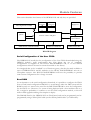
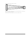
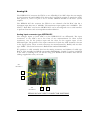
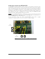
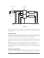
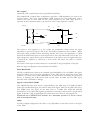
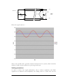
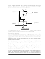
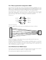
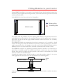
The screen of the input coaxial connectors is connected to the ground plane of the pcb.
The points on the input network marked P+ and P- are take to a input protection device
(SP723) that will limit the voltage at that point to less than 3.3V and greater than 0V.
With this input configuration the performance should be :Input Bandwidth
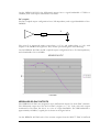
The AC coupling capacitor on the input defines the low frequency cut off, and the
converter chip input capacitance together with the protection device input capacitance will
set the upper cut off. An estimate of the resulting analogue bandwidth is 200Hz to
450MHz, from a 50 Ohm source. If the protection device is removed so lowering the stay
capacitance on the input to the converters the upper cut off frequency increases to
700MHz, which is the typical analogue input bandwidth in the AD9430 data sheet.
Signal to Noise Ratio (SNR)
The AD9430-210 data sheet shows a typical SNR for the ADC chip of 63.1dBs in CMOS
mode with a differential input, this value is taken from figure TPC6 on the ADC data sheet.
The SFDR from this figure on the data sheet is 71.1dBc. The SNR and SINAD
performance of the ADC will degrade significantly if the input is driven with a single ended
signal.
Production test of HERON-IO5 measure for a maximum spread of 8 levels of noise with
an unconnected input.
Offset
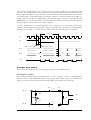
The worst case offset is defined by the ADC data sheet as +/- 3mV. To translate this into
quantised levels the converter range mode must be taken into consideration. If the input
range is set for a full 1.536Volt differential signal then the offset is equivalent to +/-8 levels.
In single ended mode where the full range of input signals is only 0.768 Volts then the
offset is equivalent to +/-16 levels.
Input level
The maximum signal window on each of the differential input pins of the ADC is 0.768
Volts. In the case of a single ended signal onto the converter, with one of the differential
inputs having no signal on it, the maximum input signal level is 0.768 Volts peak to peak. A
full differential signal, with signal on both of the differential inputs, can have a maximum
differential signal level of 1.5636 Volts peak to peak.
Impedance
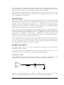
The input impedance is set to give 50R on each of the co-axial cable inputs. This gives
approximately 100R between the two differential signals (centre cores).
Optionally the input impedance of each input can be set at build. It does not make sense to
set less than 50R, and the highest impedance achievable is approximately 1.7K. In that case
the differential impedance is approximately 850R. The offset and noise performance given
in this manual relates to the 50R inputs and requesting a different impedance will affect the
offset and noise performance.
Protection
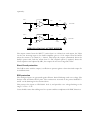
The points P+ and P- are protected against overvoltage ( >+3.3V) and undervoltage (<0v)
with respect to the HERON-IO5 0 Volts. They are also protected against static discharge.
The voltage rating of two 2.2uF capacitors sets the absolute maximum and minimum
61
HUNT ENGINEERING HERON-IO5V USER MANUAL