1
Uncommitted Module Interconnects
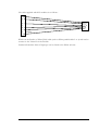
There are some “Uncommitted Interconnect” signals defined by the HERON specification,
which are simply connected to all modules.
These are intended to connect control signals between modules, for example a processor
module can (via software) drive one of these signals with one of is timer outputs. Then if an
I/O module can accept its clock input from one of these signals, it is possible to implement
a system with a programmable clock. There will be other uses for these signals that are
module design dependent.
The HERON-IO5 connects these signals to FPGA I/O pins allowing the user
configuration to use these if required.
General Purpose LEDs
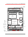
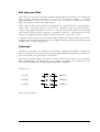
There are general purpose LEDS on the HERON-IO5, which are driven by the FPGA.
The LED’s labelled 0 to 4 are driven by the FPGA pins LED0 to LED4 respectively. The
LED will illuminate when the FPGA drives the pin low.
Other HERON module signals
There are many signals that are connected between the FPGA on the HERON-IO5 and
the HERON module connectors. Most of these signals will only be used by advanced users
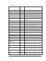
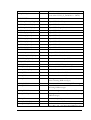
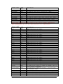
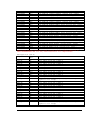
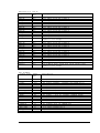
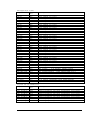
of the HERON-IO5. The FPGA pinning of these signals is shown in the appendix of this
manual, and their uses in a system is described in the HERON module specification found
on the HUNT ENGINEERING CD and Web Site.
The FPGA sets any I/O pins of the device that are not listed in the design to have a 50150K pull down. Most of the HERON module signals are pulled to their inactive state by
10K resistors so this 50K will have no effect. However the UDPRES signal does not, and
setting this signal low will cause your whole board to be reset. Thus it is important that the
UDPRES pin is driven high by the FPGA if it is not being used.
It is also advised to do the same with the LED pins to prevent them becoming illuminated
erroneously.
81
HUNT ENGINEERING HERON-IO5V USER MANUAL