1
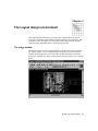
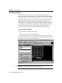
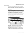
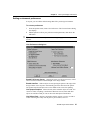
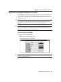
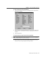
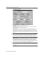
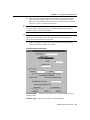
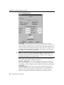
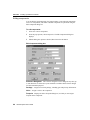
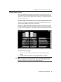
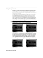
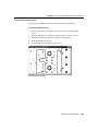
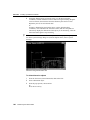
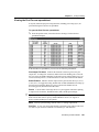
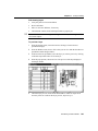
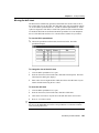
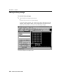
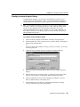
Part Two
Creating a printed circuit board
Checking the board, place, and insertion outlines
The board outline is used by Layout to determine the overall board placement
boundary, and it must be present on the global layer of the board. It can be defined
as part of the board template, or you can create it when you set up the board.
A place outline defines the extent of the area that is reserved for a component’s
placement. Each footprint must have one. Layout uses place outlines to determine
whether any component spacing violations occur during placement. A place outline
can be assigned a height and a layer. One or more place outlines of different heights
and shapes, and on different layers, can be used to more closely represent the
placement area required by a component.
6
Tip If you select the Show 3D Effects option in the User Preferences dialog box
(accessed by choosing User Preferences from the Options menu), and have
assigned a height for a place outline, Layout displays a three-dimensional image
representing the component’s height, and indicates the height on the image.
An insertion outline is optional, and is used by Layout to provide clearance for autoinsertion machines.
O
Note An insertion outline can overlap another insertion outline, but a place
outline cannot overlap another place outline.
To check board, place, and insertion outlines
&
72
1
Choose the spreadsheet toolbar button, then choose Obstacles. The Obstacles
spreadsheet displays.
2
Review the Obstacle Type column in the spreadsheet to check that the board,
place, and insertion outlines have the correct width and height, and that they are
on the correct layer (for example, the board outline must be on the global layer).
3
Close the Obstacles spreadsheet so that you can view the board outline in the
design window. If there are “cutouts” in the board outline where no components
should be placed, you need to create zero-height keepouts inside the cutouts, to
ensure that no components are placed in these areas.
See For information on creating height keepouts, see Creating height or group
keepins and keepouts in this chapter. For information on creating board outlines,
see Chapter 4: Setting up the board. For information on creating place and
insertion outlines, see Chapter 5: Creating and editing obstacles.
OrCAD Layout User’s Guide