1
AlphaServer 300
User’s Guide
Order Number: EK-AS300-UG. A01
Digital Equipment Corporation
Maynard, Massachusetts
November 1996
The information in this document is subject to change without notice and should not be construed as a commitment
by Digital Equipment Corporation.
Digital Equipment Corporation assumes no responsibility for any errors that might appear in this document.
The software, if any, described in this document is furnished under a license and may be used or copied only in
accordance with the terms of such license. No responsibility is assumed for the use or reliability of software or
equipment that is not supplied by Digital Equipment Corporation or its affiliated companies.
Restricted Rights: Use, duplication, or disclosure by the U.S. Government is subject to restrictions as set forth in
subparagraph (c) (1) (ii) of the Rights in Technical Data and Computer Software clause at DFARS 252.227-7013.
Copyright 1996 Digital Equipment Corporation.
All Rights Reserved.
The following are trademarks of Digital Equipment Corporation:
AlphaGeneration, AlphaServer, DEC, Digital, OpenVMS, ThinWire, and the DIGITAL logo.
The following are third-party trademarks:
Microsoft and Windows NT are registered trademarks of Microsoft Corporation.
UNIX is a registered trademark in the United States and other countries, licensed exclusively through X/Open
Company Ltd.
All other trademarks or registered trademarks are the property of their respective holders.
FCC Information - Class B
This equipment has been tested and found to comply with the limits for a Class B digital device, pursuant to Part 15
of the FCC rules. These limits are designed to provide reasonable protection against harmful interference in a
residential installation.
Any changes or modifications made to this equipment may void the user's authority to operate this equipment.
This equipment generates, uses, and can radiate radio frequency energy and, if not installed and used in accordance
with the instructions, may cause harmful interference to radio communications. However, there is no guarantee
that interference will not occur in a particular installation. If this equipment does cause harmful interference to
radio or television reception, which can be determined by turning the equipment off and on, the user is encouraged
to try to correct the interference by one or more of the following measures:
•
Reorient or relocate the receiving antenna
•
Increase the separation between the equipment and receiver
•
Connect the equipment into an outlet on a circuit different from that to which the receiver is connected
•
Consult the dealer or an experienced radio/TV technician for help
The user may find the following booklet prepared by the Federal Communications Commission helpful: How to
Identify and Resolve Radio-TV Interference Problems. This booklet is available from the U.S. Government Printing
Office, Washington, D.C., 20402. Stock No. 004-00398-5.
All external cables connecting to this basic unit need to be shielded. For cables connecting to option boards, see
the option manual or installation instructions.
This digital apparatus does not exceed the Class B limits for radio noise emissions set out in the radio interference
regulations of the Canadian Department of Communications.
Acoustics - Preliminary Declared Values per ISO 9296 and ISO 7779. 1B=10dBA
Sound Power Level
LWAd, B
Idle
4.8
Operate
4.9
Sound Pressure Level
LpAm, dBA
(operator position)
Idle
Operate
39
40
Table of Contents
Preface
1 System Overview
Introduction........................................................................................................................... 1-1
Motherboard.......................................................................................................................... 1-1
PCI Architecture ................................................................................................................... 1-2
System Front View................................................................................................................ 1-3
System Rear View................................................................................................................. 1-4
Security Features................................................................................................................... 1-5
Chassis Lock ........................................................................................................... 1-5
Security Loop .......................................................................................................... 1-5
Passwords................................................................................................................ 1-5
2 Getting Started
Introduction.......................................................................................................................... 2-1
Before Starting Your System................................................................................................ 2-2
Identifying the Correct AC Power Cord......................................................................... 2-3
Installing Your System ......................................................................................................... 2-4
Connecting System Parts ............................................................................................... 2-5
Console Terminals......................................................................................................... 2-7
Serial Port Connectors ................................................................................................... 2-7
Network Connection...................................................................................................... 2-7
Installing the Operating System..................................................................................... 2-8
Digital UNIX and OpenVMS.................................................................................. 2-8
Microsoft Windows NT Server ............................................................................... 2-8
Starting Your System ........................................................................................................... 2-9
v
Turning Off Your System................................................................................................... 2-10
3 Console Commands
Introduction ......................................................................................................................... 3-1
ARC Console ....................................................................................................................... 3-2
ARC Menus .................................................................................................................. 3-2
Boot Menu Functions: ............................................................................................ 3-2
Supplementary Menu Functions: ............................................................................ 3-2
Setup Menu Functions: ........................................................................................... 3-2
Booting the System ....................................................................................................... 3-3
Boot "boot selection identifier"............................................................................... 3-3
Boot an Alternate Operating System....................................................................... 3-3
Manage Boot Selection Menu................................................................................. 3-3
Setup Autoboot....................................................................................................... 3-4
Display Hardware Configuration ................................................................................... 3-4
Setting System Parameters ............................................................................................ 3-6
Set Default Environment Variables......................................................................... 3-6
Set Default Configuration....................................................................................... 3-6
Other Menu Functions................................................................................................... 3-7
Install New Firmware ............................................................................................. 3-7
Install Windows NT from CD-ROM....................................................................... 3-7
Switching from ARC to SRM Console ................................................................... 3-7
SRM Console....................................................................................................................... 3-8
SRM Console Conventions............................................................................................ 3-8
SRM Console Special Characters .................................................................................. 3-9
Boot Command ........................................................................................................... 3-10
Boot Command Examples .................................................................................... 3-11
Show Command .......................................................................................................... 3-12
Show Command Examples ................................................................................... 3-13
Set Command.............................................................................................................. 3-16
Set Command Examples....................................................................................... 3-16
Switching from SRM to ARC console .................................................................. 3-17
ISA Configuration Utilities.......................................................................................... 3-17
ICONFIG Utility .................................................................................................. 3-17
Using the Built-in ICONFIG Scripts............................................................ 3-18
Adding Options Manually ........................................................................... 3-18
ISACFG Utility ........................................................................................................... 3-20
Command Format................................................................................................. 3-20
Adding ISA Options to OpenVMS and Digital UNIX Systems ............................. 3-22
ISACFG Command Examples .............................................................................. 3-23
vi
4 Installing System Options
Introduction.......................................................................................................................... 4-1
Removing the Top Cover ..................................................................................................... 4-2
System Unit Components ..................................................................................................... 4-4
Motherboard......................................................................................................................... 4-6
Installing Additional System Memory .................................................................................. 4-7
Adding Memory Modules..................................................................................................... 4-8
Installing Expansion Boards ............................................................................................... 4-10
General Information on Installing Drives............................................................................ 4-12
SCSI Bus Length ......................................................................................................... 4-12
Internal SCSI Termination........................................................................................... 4-12
External SCSI Termination.......................................................................................... 4-13
Cable Layout ............................................................................................................... 4-13
Installing Storage Options in the Drive Bracket.................................................................. 4-17
Storage Bay........................................................................................................................ 4-22
Replacing the Battery ......................................................................................................... 4-26
Replacing the System Cover............................................................................................... 4-27
Connecting External Options.............................................................................................. 4-29
Cabling for a Printer or Other Parallel Device ............................................................. 4-29
External SCSI Options................................................................................................. 4-29
5 Troubleshooting
Introduction.......................................................................................................................... 5-1
Initial Troubleshooting ......................................................................................................... 5-1
Equipment Log..................................................................................................................... 5-2
General Troubleshooting ...................................................................................................... 5-2
Error Beep Codes ................................................................................................................. 5-9
Diagnostic LEDs ................................................................................................................ 5-10
Location of the LEDs .................................................................................................. 5-10
Interpreting the LED Indicator Values ......................................................................... 5-10
A Technical Specifications
Introduction..........................................................................................................................A–1
System Specifications...........................................................................................................A–2
Power Supply and Input Power Requirements ......................................................................A–4
Motherboard Jumpers...........................................................................................................A–4
B Updating System Firmware
Introduction..........................................................................................................................B–1
vii
Location of Firmware Updates ............................................................................................. B–1
Updating the Console Firmware ........................................................................................... B–2
Using the Flash Update Utility from the SRM Console.................................................. B–3
Using the Flash Update Utility from the ARC Console.................................................. B–5
Updating PCI Option Firmware............................................................................................ B–5
PCI Firmware Update Procedure ................................................................................... B–5
C Starting an Operating System Installation
Introduction ........................................................................................................................ C–1
Starting a Windows NT Installation .................................................................................... C–2
Starting a Digital UNIX Installation .................................................................................... C–5
Starting an OpenVMS Installation....................................................................................... C–6
D Equipment Log
Introduction .........................................................................................................................D–1
Equipment Log ....................................................................................................................D–1
Index
viii
Preface
Welcome to the AlphaServer 300 System
This guide introduces the AlphaServer 300 system.
Use the information here to start, use, update, troubleshoot, and configure your
AlphaServer 300 system. You can also find general information on the system
components, technical specifications, and console commands.
Audience
If you are operating, configuring, or adding options to the AlphaServer 300 system, the
information included here is helpful to you.
ix
Organization of the Information
This information for users covers the following topics (see the Table of Contents for a
detailed listing):
•
Chapter 1, System Overview. Motherboard, keyboard, system controls, indicators,
ports, and connections.
•
Chapter 2, Getting Started. Installing, starting, restarting, and turning off the system.
•
Chapter 3, Console Commands. Basic commands for ARC and SRM consoles.
•
Chapter 4, Installing System Options. Installing hard disk, compact disc, and tape
drives, memory, option cards, printer cable, and external SCSI cable.
•
Chapter 5, Troubleshooting. Possible causes and actions to solve problems.
•
Appendix A, Technical Specifications.
•
Appendix B, Updating System Firmware.
•
Appendix C, Starting an Operating System Installation.
•
Appendix D, Equipment Log.
Conventions
This guide uses the following conventions:
Convention Example
Description
c:\windows
Monospaced text indicates file names, path names,
directories, or screen text. Each operating system has its
own specific syntax.
[Enter]
Square brackets surrounding text represent a key on the
keyboard.
[Ctrl]+[R]
A plus sign indicates that you press both the keys shown at
the same time.
auto_action
Italic text indicates environment variables. Italic is also
occasionally used for emphasis.
)
x
A pointing hand indicates a reference to additional
information.
Abbreviations
This guide uses the following abbreviations:
Abbreviation
Meaning
ARC
Advanced RISC Computing (the Windows NT Console).
CD
Compact disc.
CD-ROM
Compact disc read-only memory.
CPU
Central processing unit.
DMA
Direct memory access.
DRAM
Dynamic random access memory.
DROM
Diagnostic read only memory.
FDC
Floppy disk controller.
flashROM
Electrically erasable, rewriteable, nonvolatile memory.
GB
A GB suffix to a numerical value indicates size in gigabytes
(for example, 1 GB). A gigabyte equals 1,073,741,824 bytes.
IRQ
Interrupt request.
ISA
Industry-standard architecture.
Kb
A Kb suffix to a numerical value indicates size in kilobits (for
example, 512 Kb). A kilobit equals 1024 bits.
KB
A KB suffix to a numerical value indicates size in kilobytes
(for example, 640 KB). A kilobyte equals 1024 bytes.
LED
Light-emitting diode.
Mb
An Mb suffix to a numerical value indicates size in megabits
(for example, 10 Mb). A megabit equals 1,048,576 bits.
MB
A MB suffix to a numerical value indicates size in megabytes
(for example, 550 MB). A megabyte equals 1,048,576 bytes.
MHz
Megahertz.
MAU
Media adapter unit.
ns
Nanoseconds.
NVRAM
Nonvolatile random access memory.
Digital UNIX
Digital UNIX operating system.
PCI
Peripheral component interconnect.
RISC
Reduced instruction set computing.
ROM
Read only memory.
xi
(continued)
Abbreviation
Meaning
SCSI
Small computer system interface.
SIMM
Single in-line memory modules.
SRM
The Digital UNIX and OpenVMS console firmware.
SROM
Serial read only memory.
VMS
OpenVMS operating system.
Special Notices
This guide uses four kinds of notices to emphasize specific information.
________________________WARNING___________________________
A WARNING indicates the presence of a hazard that can cause personal
injury.
____________________________________________________________
________________________ CAUTION ___________________________
A CAUTION indicates the presence of a hazard that can cause damage to
hardware or that might corrupt software.
____________________________________________________________
_________________________ NOTE_____________________________
A NOTE gives general information, such as compatibility with other products or
pointers to other information.
____________________________________________________________
__________________________ HINT _____________________________
A HINT includes suggestions to make your computing tasks easier.
____________________________________________________________
xii
Additional Information Resources
You may wish to consult the following information resource on your AlphaServer 300
system:
•
AlphaServer 300 Installation Information (order number EK-AS300-IN) presents a
graphical overview of the AlphaServer 300 installation.
•
AlphaServer 300 Service Information (order number AK-R2M9A-CA) provides
troubleshooting and removal and replacement procedures, presented as an on-line help
file.
•
On the Internet go to: http://www.digital.com/info/alphaserver/products.html where
you will find more information on Digital AlphaServer products.
Contact your distributor or Digital representative for other product-related information.
xiii
1
System Overview
Introduction
This chapter describes the AlphaServer 300 system hardware components, including the
motherboard, PCI architecture, keyboard, front panel controls, rear panel connectors, and
security features.
Motherboard
Your AlphaServer 300 system uses a high-performance DECchip 21064A CPU (central
processing unit). System features include:
•
2 MB cache memory.
•
Memory controller and data path that connects through a 128-bit wide data bus to
main memory and through a 128-bit wide data bus to second-level cache. The data is
longword parity protected (each set of 32 bits has a parity bit).
•
PCI bus adapter with a 32-bit wide multiplexed address/data bus.
•
Floppy disk controller that supports a floppy drive and one additional CD drive.
•
PCI-based embedded SCSI-2 controller that supports up to seven SCSI peripherals
such as hard disk drives, CD-ROM drive, and tape drives.
•
One slot for a PCI option, one slot for a PCI or ISA option, and one additional slot for
a half-size ISA option.
•
Keyboard and mouse ports, two serial ports, and one enhanced bidirectional parallel
port.
)
PCI based Ethernet adapter.
•
Refer to Appendix A, Technical Specifications, for additional information.
System Overview 1-1
PCI Architecture
Your system’s PCI architecture represents the latest advances in local bus technology. The
AlphaServer 300 system PCI architecture delivers maximum performance by providing a
wider data path, greater speed, and improved expandability. PCI removes various types of
peripheral controllers from the slower ISA bus and connects them directly to a wider,
faster data path. The result is faster data transfers for devices such as SCSI controllers and
network interface cards—a critical advantage when you are running I/O-intensive
software.
PCI local bus features include:
•
Highest performance in the market today.
•
Best expandability for high-performance peripheral devices.
•
Support for multiple bus masters.
•
32-bit data transfer at 132 MB per second (peak).
•
PCI-to-ISA bridge capability that allows you to use commonly available ISA options.
1-2 AlphaServer 300 User’s Guide
System Front View
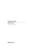
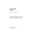
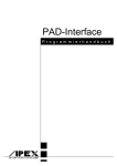
Figure 1-1 is a front view of the system showing the location of the controls and indicators.
Table 1-1 describes these items.
1
2
3
4
5
6
MLO-013121
10
9
8
7
Figure 1-1 Front Controls and Indicators
Table 1-1 Front Controls and Indicators
Figure
Legend
Control or Indicator
Function
1
Power indicator
Lights when the system is on.
2
Disk activity indicator
Lights when a hard disk drive is in use.
3
Reset button
This button resets the system and causes the
self-test to run. See Appendix A, Technical
Specifications, for directions on setting the
Reset jumper.
4
Floppy drive
Location of 3.5-inch diskette drive.
5
Floppy eject button
Push to eject the floppy disk.
6
Power on/off button
Turns AC power on and off.
7
CD-ROM eject button
Opens the CD loading drawer.
8
CD drive (optional)
5.25-inch half-size front-accessible drive
bay.
9
Hard drive (optional)
3.5-inch low-profile front-accessible hard
drive bay.
10
Louvered air intake
Passageway for cooling air to enter the
system. (Do not block air intake.)
System Overview 1-3
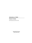
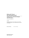
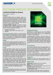
System Rear View
Figure 1-2 shows the rear connectors and lock. Table 1-2 describes their functions.
1
15
2
3
14
13
4
5
12
6
11
7
8
10
9
Figure 1-2 Rear Connectors
Table 1-2 Rear Connectors
Figure
Legend
Connector
Function
1
Voltage selector switch
Allows you to set your system to work with 115 or
230 volts AC power.
2
Keyboard connector
Use to connect a 101- or 102-key keyboard.
3
System (chassis) lock
Locks top cover.
4
Twisted pair connector
Connection to the embedded Ethernet controller .
5
ThinWire connector
Connection to the embedded Ethernet controller .
6
ISA expansion slot
Used for half-size ISA expansion options only.
7
PCI/ISA expansion slot
Either a PCI or ISA option can use this slot.
8
PCI expansion slot
Used for PCI expansion options. In this example,
a PCI graphics adapter is in the slot.
9
Security loop
Attachment point for a padlock and security cable.
10
LED viewing ports
Ports for viewing diagnostic LED indicators.
11
SCSI port
Provides the interface between the system unit and
external SCSI devices.
1-4 AlphaServer 300 User’s Guide
Table 1-2 Rear Connectors (continued)
Figure
Legend
Connector
Function
12
Enhanced bidirectional
parallel port
Connects an industry-standard parallel printer or
other parallel device.
13
Serial port connectors
Connects serial devices.
14
Mouse connector
Connects a PS/2-compatible mouse.
15
AC power connector
Connects the system to AC power.
Security Features
Chassis Lock
To avoid theft of internal components, your AlphaServer 300 system comes with a chassis
key lock, which is located on the back of your system box. When this lock is in the locked
position, the system box cover cannot be removed. Store the key in a safe place.
Security Loop
The security loop discourages theft of your system unit. The loop is designed to be used
with a padlock and secure cable.
Passwords
For additional security, most screen saver and pause screen displays can have password
protection enabled.
System Overview 1-5
2
Getting Started
Introduction
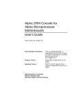
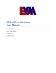
Your AlphaServer 300 system is a high-performance system that uses the latest
microprocessor technology. This chapter describes how to install, turn on, boot, and turn
off your AlphaServer 300 system. Figure 2-1 shows a typical AlphaServer 300 system.
MLO-011053
Figure 2-1 AlphaServer 300 System
Getting Started 2-1
Before Starting Your System
Before starting your system, perform the following steps:
1.
Read and understand the information supplied with your system.
2.
Select a well-ventilated site near a grounded power outlet and away from sources of
excessive heat. The site should also be isolated from electric noise (for example,
spikes, sags, and surges) produced by devices such as air conditioners, large fans,
radios, and televisions.
3.
Save all shipping containers and packing material for repackaging or moving the
system later.
_________________________ NOTES ____________________________
1. Do not install optional hardware or application software until you have
started your system and verified that the base system is working correctly.
2. On systems that have preloaded software, a label attached to the system unit
informs you that licensed software has been installed. Carefully review the
software license agreement shipped with your system.
____________________________________________________________
________________________WARNING___________________________
When unpacking and moving system components, be aware that some
components (such as the system unit or monitor) may be too heavy for you
to safely lift alone. If you are doubtful about whether you can lift these
items alone, please get assistance.
____________________________________________________________
2-2 AlphaServer 300 User’s Guide
Identifying the Correct AC Power Cord
A country specific detachable power supply cord will be provided or specified for your
AlphaServer 300 system. As there are variations from one country to another, and systems
may be moved, please inspect your power cord to ensure it is the correct one for your
country or region. If you are not sure that the supplied AC power cord is correct, contact
your authorized Digital service representative before you use it.
________________________ WARNING __________________________
Do not attempt to modify or use an external 115-volt AC power cord for
230-volt AC input power. Modifying the power cord can cause personal
injury and severe equipment damage.
____________________________________________________________
Power cords for AlphaServer 300 systems must meet the following criteria:
•
Within the U.S. and Canada, this cord set will be Listed, Certified*, SVT, #18AWG,
3-conductor, grounding type, rated minimum 125V, 10A.
•
In other countries, this cord set will be <HAR>, minimum 1.0mm2, rated minimum
250V, 6A, with plugcap appropriate for the country where used.
Getting Started 2-3
Installing Your System
The AlphaServer 300 Installation Information accompanying your system shows the steps
to follow when installing your system.
_______________________ CAUTIONS __________________________
1. To ensure that your system is properly cooled, make sure that air can freely
flow into the front and out of the rear of the system unit.
2. The system is designed to be placed horizontally on a desktop. Do not use a
stand or rack that would hold the system on its side.
____________________________________________________________
Check to make sure that you received all your system components. (See Appendix D,
Equipment Log, to list your equipment.) If something is missing, please contact your
distributor or Digital representative.
Position your system so that air can flow freely to and from the vents, as shown in Figure
2-2.
MLO-011125
Figure 2-2 System Airflow
2-4 AlphaServer 300 User’s Guide
Connecting System Parts
To connect the components of your AlphaServer 300 system, perform the following steps:
1.
Confirm that the voltage selector switch matches your local voltage (either 115 volts
or 230 volts), as Figure 2-3 shows.
115V
230V
Figure 2-3 Voltage Selector Switch
________________________ CAUTION___________________________
Improper voltage selection can damage the system's power supply.
____________________________________________________________
2.
Ensure that the power switch is in the off (out) position. Refer to your system's
Installation Information for a view of the positions of this switch.
3.
Connect the mouse, keyboard, video cable, and power cords to the system
components, as Figure 2-4 shows.
Getting Started 2-5
1
2
Figure 2-4 Connecting Cables and Power Cords
4.
If you have an external SCSI device or SCSI storage box, connect the SCSI cable to
the SCSI port on the rear of the system. See the SCSI termination section in Chapter
4.
2-6 AlphaServer 300 User’s Guide
Console Terminals
The AlphaServer 300 system supports two types of console terminals, a graphics terminal
and a serial terminal. The console terminal is used to configure the system and boot the
operating system. From the console terminal, you can issue commands to the system when
the operating system is not running. If you are using the Windows NT operating system, a
graphics terminal is required. If you are using either OpenVMS or Digital UNIX, the
terminal may be graphics or serial.
•
The graphics terminal attaches to the graphics adapter card on the back of the system.
(This terminal is shown on the right side of Figure 2-4.) The “console” environment
variable should be set to “graphics.”
•
The serial terminal attaches to the COM1 port on the back of the system. (This
terminal is shown at the bottom of Figure 2-4.) The “console” environment variable
should be set to “serial.”
)
See Chapter 3, Console Commands, for more information on environment
variables.
Serial Port Connectors
The serial port connectors consist of two 9-pin D-subminiature connectors.
The baud rates supported by the system's serial ports are 50, 75, 110, 134.5, 150, 300, 600,
1200, 1800, 2000, 2400, 3600, 4800, 7200, 9600, 19200, 38400, and 57600 (56000 with
approximately 3% error), and 115200.
)
Refer to your operating system documentation to confirm which baud rates
are supported by your operating system.
Network Connection
Connect your network interface cable to the appropriate port on your network module. If
you are using the Digital UNIX or OpenVMS operating systems, the ThinWire port is
selected by default. You can change to the twisted-pair port by entering the following
SRM console command:
>>>set ewa0_mode twisted (See Chapter 3, Console Commands.)
Getting Started 2-7
Installing the Operating System
Digital UNIX and OpenVMS
If you ordered a Digital UNIX or OpenVMS version of the AlphaServer 300 system, your
operating system came preloaded.
You may encounter a special circumstance that requires you to reload your operating
system, In such a case, refer to your operating system documentation for information on
loading. Also refer to Appendix C, Starting an Operating System Installation.
Microsoft Windows NT Server
If you ordered a system with a Microsoft Windows NT license, the operating system is not
preloaded. However, Disk 0 on the first SCSI bus is partitioned and formatted so that you
can immediately install the operating system. Refer to your operating system
documentation for information on loading.
2-8 AlphaServer 300 User’s Guide
Starting Your System
1.
Turn on the system unit power, monitor power, and any external devices. Figure 2-5
shows the location of the system unit power button.
MLO-011054
Figure 2-5 Starting Your System
2.
If necessary, adjust the monitor contrast and brightness to obtain a readable screen
display. (Refer to the information supplied with your monitor for further instructions.)
3.
Allow your system to complete any power-on self-tests and device initialization
messages. During initialization, you will see information scroll by quickly on the
screen. (This takes approximately 1 minute.)
4.
If you are booting Digital UNIX or OpenVMS, the system halts and displays the SRM
console prompt (>>>). You can now boot the operating system using the boot
command. (See boot command in the SRM console section of Chapter 3.) If the
environment variable auto_action is set to boot, the system will boot automatically
without using a boot command. (See the SRM environment variables section of
Chapter 3 for more information.)
5.
If you are booting Windows NT, the system normally halts and displays the ARC
console Boot Menu. You can now boot the system by selecting Boot Windows NT
menu choice. (See the ARC console section of Chapter 3 for more information on the
Boot Menu.) If autoboot is enabled, the system will boot automatically without using
the menu. (See Setup Autoboot in the ARC console section of Chapter 3 for more
information on setting autoboot and other system parameters.
Getting Started 2-9
Turning Off Your System
Before turning off your system, make sure to save and close all open files. If you turn the
system off without saving and closing files, you might lose some or all of your work.
Perform the following steps to turn off your system:
1.
Close any application data files you have open as well as any applications you have
running. Most application programs prompt you to save the information before
closing.
2.
Shut down the operating system with the appropriate command from Table 2-1.
Table 2-1 Operating System Shutdown
Operating System
Action
Microsoft Windows NT
From the Program Manager File Menu, choose Shutdown.
Choose the OK button to confirm.
Digital UNIX
Type the following from a superuser account:
shutdown -h now
OpenVMS
Type the following from a privileged account:
@sys$system:shutdown
3.
Wait for the operating system to complete the shutdown process. For OpenVMS and
Digital UNIX, the SRM console prompt (>>>) is displayed. Microsoft Windows NT
displays a window indicating it is safe to turn off or restart the system.
4.
Do not turn off power to your system and peripherals until the shutdown sequence has
completed.
2-10 AlphaServer 300 User’s Guide
3
Console Commands
Introduction
The AlphaServer 300 system contains two console subsystems: ARC firmware that
supports the Microsoft Windows NT operating system, and SRM firmware that supports
the Digital UNIX and OpenVMS operating systems. The console firmware resides in
flashROM on the motherboard. The user is responsible for performing system firmware
upgrades. Consult Appendix B, Updating System Firmware, for more information.
This chapter gives a basic description of each console's commands.
Console Commands 3-1
ARC Console
The ARC console has a menu interface that supports the use of the Microsoft Windows NT
operating system. When an AlphaServer 300 system with Microsoft Windows NT is
powered on, initialization is performed. During initialization, the firmware checks the
information stored in the nonvolatile memory. If the information is unreadable or
inconsistent, a warning message is displayed. The warning message identifies the areas
that must be fixed prior to booting Microsoft Windows NT. If the information is correct, a
menu similar to the following displays after initialization:
Alpha Firmware Version 4.49
Copyright (c) 1993-1996 Microsoft Corporation
Copyright (c) 1993-1996 Digital Equipment Corporation
Boot menu:
Boot Windows NT
Boot an alternate operating system
Run a program
Supplementary menu...
Use the arrow keys to select, then press Enter.
ARC Menus
The ARC console consists of three primary menus: Boot, Supplementary, and Setup.
Boot Menu Functions:
• Boot the default boot selection
•
Boot an alternate boot selection
•
Run a program
•
Access the Supplementary menu
Supplementary Menu Functions:
• Install new firmware
•
Install Microsoft NT from a compact disc
•
Access the Setup menu
•
Display the hardware configuration
•
Return to the Boot menu
Setup Menu Functions:
• Set the system time
•
Set the default system partition
3-2 AlphaServer 300 User’s Guide
•
Configure the system floppy drives and keyboard
•
Manage the ARC boot selections
•
Set the system to boot automatically
•
Edit the system environment variables
•
Reset the system to factory defaults
•
Set the default operating system and system firmware
•
Return to the Supplementary menu, with or without saving Setup menu changes
Booting the System
Boot "boot selection identifier"
Selecting this menu item causes the system to boot the default operating system. The boot
selection identifier, Windows NT in this case, uses values that were set up with the
“Manage boot selection” menu. The default boot selection identifier is the identifier at the
top of the identifier list. When the Boot Windows NT command is selected, you will see
something similar to the following:
OS Loader V3.5
.............
Microsoft (R) Windows NT (TM) Version 3.5
1 System Processor [49128 Kb memory]
Checking file system on C:
The type of file system is FAT.
The volume is clean.
The screen then displays a Microsoft Windows NT Server graphic and the Welcome box
appears.
Boot an Alternate Operating System
The “Boot an alternate operating system” command is located in the Boot menu. Use this
command to select a boot selection identifier that is different from the default selection.
For example, you could have multiple versions of Microsoft Windows NT installed, each
with its own unique boot selection identifier; use this command to select the version you
want to boot.
Manage Boot Selection Menu
Reach the “Manage boot selection menu” from the Setup menu. Use the manage boot
selection menu to add, change, check, delete, dump (list), and rearrange boot selections.
Console Commands 3-3
Initially, select Add a boot selection. You are then prompted to select:
•
A system partition for this boot selection (The partition defined by the Set default
environment variables command should be one of your choices.)
•
The osloader directory and name
•
Whether or not the operating system is in the same partition as the osloader
•
The operating system root directory
•
A name (identifier) for this boot selection
•
Whether or not the debugger should be initialized at boot time
After you have added a boot selection, use the “Check boot selections” command to
perform verification testing of the selections. If an error is detected, you are prompted to
ignore, delete, or change the boot selection.
Setup Autoboot
The “Setup autoboot” command is located in the Setup menu. Use this command to
enable automatic booting of the system. When you enable autoboot, you will also be
prompted to enter a countdown value. (The default is 10 seconds.) The ARC console will
wait for the duration of the countdown value before booting the system.
Display Hardware Configuration
This choice, located in the Supplementary menu, displays a list of available hardware
devices on your system. An example of the hardware configuration screen display follows
the bulleted section.
•
The first screen displays processor information, the amount of memory installed, and
the type of video card installed.
•
The second screen displays devices detected by the firmware. Multi() devices include
the monitor, keyboard port, and serial line ports. SCSI() devices are SCSI disk, tape,
or CD-ROM devices.
•
The third screen displays PCI devices, including a SCSI controller, ISA bridge chip
(super I/O chip), Ethernet controller, memory (NVRAM board), and VGA controller.
Alpha Processor and System Information:
Processor ID
Processor Revision
System Revision
Processor Speed
Physical Memory
21064
3
0x1
266 MHz
64 MB
Extended Firmware Information:
Version: 4.49 960719.1755
3-4 AlphaServer 300 User’s Guide
NVRAM Environment Usage: 10%
(329 of 3052 bytes)
Video Option detected:
BIOS controlled video card
Press any key to continue...
Monday, 11-11-1996
5:05:38 PM
Devices detected by the firmware:
multi(0)video(0)monitor(0)
multi(0)key(0)keyboard(0)
multi(0)disk(0)fdisk(0)
(Removable)
multi(0)serial(0)
multi(0)serial(1)
scsi(0)disk(1)rdisk(0)
(RAW)
DEC
RZ28B
** scsi(0)tape(5)tape(0)
DEC
TLZ06
scsi(0)cdrom(6)fdisk(0)(Removable) DEC RRD45
(C) DEC0006
(C) DEC4BQE
(C) DEC 1084
** --> Devices detected but not supported by the firmware.
Press any key to continue...
Monday, 11-11-1996
5:05:38 PM
PCI slot information:
Bus
#
---0
0
0
0
0
Device
#
-----6
7
11
12
13
Function
#
-------0
0
0
0
0
Vendor Device Revision Interrupt Device
ID
ID
ID
Vector
Type
------ ------ -------- --------- -----1000
1
2
6
SCSI
8086
484
84
0
ISA bridge
1011
2
23
a
Ethernet
1011
7
2
f
Memory
1011
d
22
9
VGA
Press any key to continue...
Console Commands 3-5
Setting System Parameters
Set Default Environment Variables
The “Set default environment variables” command is located in the Setup menu. Use this
command to specify the location of the default system partition. Press ESC to return to the
previous menu.
Enter location of default system partition:
Select media:
SCSI Hard Disk
Floppy Disk
CD-ROM
Enter SCSI bus number: 0
Enter SCSI ID: 0
Enter partition [must be FAT or NTFS]: 1
Set Default Configuration
The “Set default configuration” command is located in the Setup menu. Use this
command to select monitor resolution, floppy drive capacity, keyboard language, and
SCSI controller (Host) ID.
Select monitor resolution:
1280x1024
1024x768
800x600
640x480
Select floppy drive capacity:
5.25" 1.2MB
3.5" 1.44MB
3.5" 2.88MB
Select second floppy drive capacity:
5.25" 1.2MB
3.5" 1.44MB
3.5" 2.88MB
None
Select keyboard:
U.S.
Japanese
French
German
Spanish
101-key
106-key
102-key
102-key
102-key
keyboard
keyboard
keyboard
keyboard
keyboard
.
.
.
Enter SCSI Host ID (0-7) for SCSI bus number 0: 7
3-6 AlphaServer 300 User’s Guide
Other Menu Functions
Install New Firmware
The “Install new firmware” command is located in the Supplementary menu. Use this
command to install firmware upgrades. When selected, the floppy drive and CD-ROM
(compact disc read only memory) will be checked for the firmware update tool. If the
proper media is not present, this command will time out. Follow the instructions packaged
with the firmware update or refer to Appendix B, Updating System Firmware, in this
guide.
Install Windows NT from CD-ROM
The “Install Windows NT from CD-ROM” command is located in the Supplementary
menu. You will need to insert the Microsoft Windows NT CD into the CD-ROM drive
before selecting this command.
Switching from ARC to SRM Console
To switch from the ARC console (used with the Microsoft Windows NT operating system)
to the SRM console (used with the OpenVMS and Digital UNIX operating systems),
follow these steps from the Boot menu:
•
Select the Supplementary menu
•
Select the Setup menu
•
Select “Switch to OpenVMS or Digital UNIX console”
•
Choose which operating system should be launched at the next power cycle
•
Select the Setup menu
•
Power cycle the system to implement the change; leave the system off for at least 20
seconds.
Console Commands 3-7
SRM Console
The SRM console supports the OpenVMS and Digital UNIX operating systems. The SRM
console is a command line interface. For a complete list of SRM commands, type help at
the SRM prompt (>>>). This section describes console conventions, special characters,
environment variables, and the following commands:
•
boot
•
set
•
show
This section also describes two SRM utilities that are used to configure ISA options.
•
iconfig
•
isacfg
SRM Console Conventions
Table 3-1 SRM Console Conventions
Item
Convention
Console prompt
>>>
Maximum command length
255 characters
Multiple contiguous spaces or tabs
Treated as a single space
Command abbreviations
Allowed, if not ambiguous
Command qualifiers or options
Prefix with a space and a dash "-"
Numbers
Hexadecimal, unless otherwise specified. (Note
that registers such as R0–R31 are shown in
decimal notation.)
3-8 AlphaServer 300 User’s Guide
SRM Console Special Characters
Table 3-2 SRM Console Special Characters
Character/Key(s)
Function
Return
Terminates command line input.
Backspace
Deletes the previously typed character.
[Ctrl]+[A]
Toggles insert/overstrike mode. (Overstrike is the default.)
[Ctrl]+[B], or up arrow
Recalls previous commands. (The last 16 commands are stored.)
[Ctrl]+[C]
Terminates the foreground process.
[Ctrl]+[E]
Moves the cursor to the end of the line.
[Ctrl]+[F] or right
arrow
Moves the cursor right one position.
[Ctrl]+[H]
Moves the cursor to the beginning of the line.
[Ctrl]+[O]
Stops console output
[Ctrl]+[Q]
XON, Resume flow of data to the console.
[Ctrl]+[S]
XOFF, Stops the flow of data to the console.
[Ctrl]+[U] or [Ctrl] +
[D]
Deletes the entire line.
[Ctrl]+[R]
Retypes the current command line.
Console Commands 3-9
Boot Command
The boot command performs the following functions:
•
Initializes the processor
•
Loads a program image from the specified boot device
•
Transfers control to the loaded image
The syntax of the boot command is:
boot [-file <filename>] [-flags <longword>[,<longword>]]
[-protocols <enet_protocol>] [-halt] [<boot_device>]
The boot command options are described in Table 3-3.
Table 3-3 SRM Boot Command Options
Command Option
Description
-file <filename>
Specifies the name of a file to load into the system. For
booting from Ethernet, this name is limited to 15
characters. Use the set boot_file command to set the
environment variable that specifies a default boot file.
-flags
<longword>[,<longword>]
Specifies additional information for the operating system.
For systems with OpenVMS, root number and boot flags
are specified here. For Digital UNIX systems, the
following values may be used:
i = interactive boot
s = boot to single user
a = autoboot to multiuser
Use the set boot_osflags command to set an environment
variable that specifies a default boot flag value.
-protocols <enet_protocol>
Specifies the Ethernet protocol(s) that will be used for a
network boot. Values may be mop or bootp.
-halt
Forces the bootstrap operation to halt and invoke the
console program after the image is loaded and the page
tables and other data structures are set up.
<boot_device>
Specifies a device path or list of devices that the firmware
will attempt to boot. Use the set bootdef_dev command
to set an environment variable that specifies a default boot
device.
3-10 AlphaServer 300 User’s Guide
Boot Command Examples
Table 3-4 SRM Boot Command Examples
Command
Description
>>>boot
Boots the system from the default boot
device.
>>>boot ewa0
Boots the system from Ethernet port ewa0.
>>>boot -file dec2.sys ewa0
Boots the file named dec2.sys from
Ethernet port ewa0.
>>>boot -protocol bootp ewa0
Boots using TCP/IP BOOTP protocol from
Ethernet port ewa0.
>>>boot -flags 0,1
Boots the system from the default boot
device using flag settings 0,1.
>>>boot -halt dka0
Loads the image from disk dka0, but
remains in console mode.
Console Commands 3-11
Show Command
The show command displays the current value of a specified environment or displays
information about the system.
The syntax of the show command is:
show [{config, device, map, memory, pal, version, <envar>...}]
The show command options are described in Table 3-5. Environment variables are listed
in Table 3-6.
Table 3-5 SRM Show Command Options
Command Option
Description
config
Displays the current memory configuration, PCI logical
slots, and ISA logical slots (based on ISACFG utility input
to the configuration database).
device [device name]
Displays the devices and controllers in the system.
Specifying a device name returns information on that
device only.
<envar>
Displays the value of the environment variable specified.
error
Displays error log information.
map
Displays the system virtual memory map.
memory
Displays the memory module configuration.
pal
Displays the version of OpenVMS and Digital UNIX
PALcode.
version
Displays the version of the console firmware.
3-12 AlphaServer 300 User’s Guide
Show Command Examples
>>>show device
dka0.0.0.6.0
dka400.4.0.6.0
dva0.0.0.0.1
ewa0.0.0.12.0
pka0.7.0.6.0
DKA0
RZ26L 441A
DKA400 RRD43 3213
DVA0
EWA0 08-00-2B-E2-1C-25
PKA0
SCSI Bus ID 7
>>>show memory
64 Meg of System Memory
Bank 0=32 Mbytes (8 MB per Simm)
Starting at 0x2000000
Bank 1=32 Mbytes (8 MB per Simm)
Starting at 0x0
Bank 2 = No Memory Detected
>>>show config
Firmware
SRM Console:
ARC Console:
PALcode:
Serial ROM:
Diag ROM:
X3.8.5
4.49
VMS PALcode X5.48-85,
UNIX PALcode X1.35-55
V4.4
V1.2
Processor
DECchip (tm) 21064-2
266Mhz 2MB Cache
MEMORY
32 Meg of System Memory
Bank 0 = 32 Mbytes(8 MB Per Simm)
Starting at 0x0
Bank 1 = 32 Mbytes(8 MB Per Simm)
Starting at 0x2000000
Bank 2 = No Memory Detected
PCI Bus
Bus 00 Slot 06: NCR 810 SCSI Controller
pka0.7.0.6.0
SCSI Bus ID 7
dka0.0.0.6.0
RZ26L
dka400.4.0.6.0 RRD43
Bus 00 Slot 07: Intel SIO 82378
Console Commands 3-13
Bus 00 Slot 10: Digital Network
Controller
ewa0.0.0.10.0
08-00-2B-E2-1C-25
Bus 00 Slot 11: Digital ZLXp Graphics
Controller
ISA
Slot Dev Name Type
Enable BaseAd
0
0 MOUSE Embedded Yes 60
1 KBD
Embedded Yes 60
2 COM1 Embedded Yes 3f8
3 COM2 Embedded Yes 2f8
4 LPT1 Embedded Yes 3bc
5 FLOPPY Embedded Yes 3f0
2
0 PCXBJ Singleport Yes 530
IRQ DMA
12
1
4
3
7
6
2
9
0
>>>show language
36
Notice that 36 corresponds to the value in Table 3-6; in this case, English (American) is
the default language. Other environment variables can be specified:
>>>show console
graphics
3-14 AlphaServer 300 User’s Guide
Table 3-6 SRM Environment Variables
Variable
Description
auto_action
Sets/shows the console action following an error, halt, or power-up.
The action can be halt, boot, or restart. Halt is the default.
boot_file
Sets/shows the file name to be used when a bootstrap requires a file
name. The default setting is null.
boot_osflags
Sets/shows additional parameters to be passed to system software.
When using OpenVMS software, these parameters are the system
root number and boot flags. The default setting is 0,0.
bootdef_dev
Sets/shows the default device or device list from which the system
will attempt to boot. If the system software is preloaded, the
variable is preset to point to the device containing the preloaded
software. Otherwise, the default value is null.
console
Sets the console output to either the COM1 serial port or the graphics
controller.
control_scsi_term
Unused in the AlphaServer 300 system.
ewa0_mode
Determines whether the AUI (ThinWire) or the twisted-pair Ethernet
ports is enabled. AUI is the default. (Auto-sensing is not supported.)
language n
The language environment variable associates language n to the
system (where n is the number of the language shown below). You
can have the system prompt you for the language using the following
command: >>>set language 0 and then >>>init. Power
cycle the system after you have set the language.
n Language
n Language
0 none (display menu)
30 Dansk
32 Deutsch
34 Deutsch (Schweiz)
36 English (American)
38 English (British/Irish)
3A Espanol
3C Francais
3E Francais (Canadian)
40 Francais (Suisse Romande)
42 Italiano
44 Nederlands
46 Norsk
48 Portugues
4A Suomi
4C Svenska
4E Vlaams
os_type
Sets/shows the specified operating system (NT, OpenVMS, or
Digital UNIX) that NVRAM will boot.
pci_parity
This variable controls PCI parity checking at the PCI bridge chip.
The default setting is off, and should remain at default.
Console Commands 3-15
Set Command
The set command is used to set or modify the value of an environment variable.
Environment variables are used to pass configuration information between the console
firmware and the operating system.
The syntax of the set command is:
set <envar> <value> [-default] [-integer] [-string]
The set command options are described in Table 3-7.
Table 3-7 SRM Set Command Options
Command Option
Description
<envar>
The environment variable to be assigned a new value.
<value>
The value that is assigned to the environment variable. It
can be either a numeric value or an ASCII string.
-default
Restores an environment variable to its default value.
-integer
Creates an environment variable as an integer.
-string
Creates an environment variable as a string.
Set Command Examples
Table 3-8 SRM Set Command Examples
Command
Description
>>>set bootdef_dev ewa0
The default boot device is set to ewa0.
>>>set auto_action boot
The console attempts to boot following an error, halt, or
power-up.
>>>set osflags 0,1
The default boot flags are set to 0,1.
>>>set foobar 5
An environment variable called foobar is created and given
a value of 5.
>>>set os_type nt
Sets up the system to start the ARC console after the next
power cycle.
3-16 AlphaServer 300 User’s Guide
Switching from SRM to ARC console
To switch from the SRM console to the ARC console, follow these steps:
•
At the SRM prompt, type >>>set os_type nt
•
Power cycle the server. (Leave the system off for at least 20 seconds.)
•
The ARC console Boot menu appears.
ISA Configuration Utilities
ISA devices are not capable of being probed for configuration information by the Digital
UNIX or OpenVMS operating systems. Therefore, you must configure ISA option
information manually before installing a new ISA option module on an AlphaServer 300
system running either Digital UNIX or OpenVMS.
There are two SRM utilities that can be used to configure ISA options: the ICONFIG
utility and the ISACFG utility.
•
The ICONFIG utility is a subset of the ISACFG utility. ICONFIG contains scripts to
configure one module of each of the three following types: DE205 Ethernet card,
PBXJA-AA sound card, and PB2GA-FB graphics card.
•
The ISACFG utility is a command line utility. It is useful for configuring more than
one ISA module of each type, for example a second DE205 card or two non-Digital
ISA options.
The ICONFIG utility and the ISACFG utility are described in the following sections.
ICONFIG Utility
To start the ICONFIG utility, type iconfig at the SRM console prompt. The following
display appears. Note that the ISA options shown below are factory configured and cannot
be deleted.
ISA CONFIGURATION UTILITY
Name
I/O IRQ DMA Mem
MOUSE
KBD
COM1
COM2
LPT1
FLOPPY
60
60
3f8
2f8
3bc
3f0
12
1
4
3
7
6
2
Length
Enabled
Y
Y
Y
Y
Y
Y
HELP: Enter up to 15 char device name
Console Commands 3-17
KEY HELP: Arrows/TAB to move, RET once to submit entry, RET
2nd time to exit
Using the Built-in ICONFIG Scripts
There are three types of options that can be configured into the AlphaServer 300 system
using a built-in script: the DE205 Ethernet module, PBXJA-AA sound module, and
PB2GA-FB graphics module (MACH 64). You can use a script to configure only one
module of each type. Enter the help scripts command to view the available scripts. (Note
that the PCXDF-AA fax/modem module is not supported on the AlphaServer 300.)
>>>help scripts
NAME
scripts
FUNCTION
These scripts are used to set up the system
configuration.
SYNOPSIS
Available scripts:
add_de205
Adds DE205 module
add_fax
Adds FAX module
add_sound
Adds SOUND module
add_mach64
Adds ATI-MACH64 module
To add a module, type the script name. You must also type init to submit the entry. For
example, add a PB2GA-FB (MACH64) graphics module as follows:
>>> add_mach64
>>> init
After the system initializes, type iconfig to view the configured options. The MACH64
module now appears in the display, and you can turn off the system and install the module.
Adding Options Manually
If you are configuring more than one of the same type of ISA option (for example, two
non-Digital Ethernet options), you must enter the configuration information manually.
3-18 AlphaServer 300 User’s Guide
__________________________NOTE ____________________________
Type information carefully. If you make a typing error, you cannot correct it.
Type Ctrl/X to exit the utility. Then type iconfig and begin again. To delete an
entry you created, position the cursor on the first column of the entry and press
the Backspace key.
____________________________________________________________
To add a second ISA option, type iconfig at the >>> console prompt. Enter the device
name, then tab to the next field and enter the I/O address, and so forth. For example, to
add a second DE205 Ethernet controller to the database, follow these steps:
1. Enter up to 15 chars device name
DE200-LE [TAB]
2. Enter I/O address in hex
300 [TAB]
3. Enter IRQ channel in decimal
5 [TAB]
4. Enter dma channel in decimal
[TAB]
5. Enter memory address in hex
d0000 [TAB]
6. Enter length of memory in hex
10000 [TAB]
7. Enter N to disable, Y to enable
Y [RETURN]
8. Initialize the system.
>>>init
9. View the new entry
>>>iconfig
10. Turn off the system and install the new module.
__________________________NOTE ____________________________
The available IRQ values for ISA options are 5, 9, 10, 14, and 15. On Windows
NT systems, IRQs 9, 10, 11, and 15 are preassigned to PCI options, if such
options are installed.
____________________________________________________________
If IRQ conflicts exist, a message is displayed. For example, if you entered an IRQ value
of 8 instead of 5, the following message is displayed:
ISACFG MESSAGE: ERROR:
(0,2,8,11 or 13)
IRQ conflict with reserved IRQ values
If you entered a DMA value of 2 rather than nothing, the following message is displayed:
ISACFG MESSAGE:
ERROR:
DMA conflict with slot 0 dev 5
Console Commands 3-19
ISACFG Utility
Command Format
The syntax of the ISACFG command is:
isacfg [-slot <slot#>] [-dev <device#>]
[-all|-rm|-mk|-mod] [-<field> <value>] . . .
The ISACFG command options are described in Table 3-9.
Table 3-9 SRM ISACFG Command Options
Command Option
Description
-all
Shows the entire configuration table. Overrides all other
commands.
-dev <dev#>
Optional; defaults to 0 if not entered. On a multifunction or
multiport adapter, this specifies the device on the adapter.
-dmachan{0-3} <#>
Allows you to specify up to four DMA (direct memory access)
channels for the device.
-dmamode{0-3} <#>
Allows you to specify the DMA type for -dmachan{0-3}. DMA
modes are:
1 - Block
2 - Demand
4 - Single
8 - Cascade
-enadev <#>
Allows you to specify whether an entry is enabled or disabled.
Disabled devices are not used in resource allocation calculations.
The possible values are:
0 - No (disabled)
1 - Yes (enabled)
3-20 AlphaServer 300 User’s Guide
Table 3-9 SRM ISACFG Command Options (continued)
Command Option
Description
-etyp <#>
Defines an entry type for this entry. The # sign can be:
0 - Causes the entry to be deleted
1 - Single option
2 - Embedded multiport device
3 - Multiport option device
-handle <string>
Binds a name to the driver (up to 15 characters).
-init
Initializes the configuration table to the default settings.
-iobase{0-5} <#>
Specifies up to six I/O base registers (in hexadecimal) for a
particular device entry.
-irq{0-3} <#>
Allows you to assign up to four IRQ (interrupt request) channels
to the device (use decimal IRQ levels).
-membase{0-2} <#>
Specifies up to three R/W ISA memory regions.
-memlen{0-2} <#>
Specifies the length corresponding to membase{0-2}.
-mk
Adds an entry into the table.
-mod
Modifies an entry in the table.
-rm
Deletes an entry from the table.
-rombase <#>
Specifies an address for ISA BIOS ext. ROM.
-romlen <#>
Specifies length of ROM.
-slot <slot#>
Allows you to enter a unique slot number for each ISA adapter.
You may assign the numbers in any order. The slot number does
not relate to a physical ISA adapter position. Slot 0 is reserved
for the local multiport adapter.
-totdev <#>
Placeholder for you to keep track of the total number of devices,
specified by the # sign, at this slot. Modify this for your own
use.
Console Commands 3-21
Adding ISA Options to OpenVMS and Digital UNIX Systems
When you need to add more than one ISA option of the same type to an AlphaServer 300
system running the OpenVMS or Digital UNIX operating system, perform the procedure
shown in Table 3-10.
Table 3-10 Adding Options to OpenVMS or Digital UNIX Systems
Step
Action
Result or Next Step
1
>>>isacfg options
Adds the new ISA option to the SRM console
configuration table using the appropriate
command options.
2
>>>init
Typing init allows the changes to be used.
3
Configure the ISA option.
Use the manual that came with your ISA
option to set the proper configuration.
4
Turn off the system and install the
ISA option.
Refer to Chapter 4.
5
Turn on the system and boot.
The operating system boots and sees the new
ISA option.
3-22 AlphaServer 300 User’s Guide
ISACFG Command Examples
This section shows examples of ISACFG commands you use to enter the DE205 into the
configuration database. Examples to display, modify, and remove table entries are also
included. In some cases, there are scripts available to issue the proper ISACFG command.
Script commands are preceded by an "add_" prefix. Long commands can be continued on
the next line by typing a backslash "\" at the end of the line.
Adding the DE205 option:
>>>add_de205
-or>>>isacfg -slot 1 -dev 0 -mk -handle DE200-LE \
_> -irq0 5 -iobase0 300 -membase0 d0000-etyp 1 -enadev 1
Displaying the full configuration database:
>>>isacfg -all
Modifying the IRQ0 entry of an option:
>>>isacfg -mod -slot 1 -irq0 14
Removing an entry:
>>>isacfg -rm -slot 1 -dev 0
Console Commands 3-23
4
Installing System Options
Introduction
This chapter covers the following topics related to installing system options on your
AlphaServer 300 system:
•
Opening and closing the system cover
•
Installing additional system memory
•
Installing expansion boards
•
Cable layout for power, SCSI, and FDC cables
•
Installing internal drives
•
Connecting external devices
•
Replacing the battery
Installing System Options 4-1
Removing the Top Cover
To remove the top cover, perform the following steps:
1.
Turn off your system and all peripheral devices.
2.
Unplug the power cord and remove the monitor power cord (if connected) and video
cable.
3.
Unlock the top cover by turning the key counterclockwise.
__________________________ HINT _____________________________
Occasionally, the top cover of the system is pushed back during shipping. This
can cause a misalignment of the locking mechanism, which makes operating the
key lock difficult. To remedy this, push the top cover toward the bezel; this
aligns the cover, allowing you to operate the key lock properly.
____________________________________________________________
_______________________ CAUTIONS __________________________
1. To avoid system damage from static discharge, touch bare (unpainted) metal
on the system box before you touch anything inside the system.
2. To avoid system damage from overheating, be careful not to run the system
without the top cover in place for extended periods of time.
____________________________________________________________
4.
To remove the cover, place your thumbs on the upper corners of the rear panel, pull
back on the cover sides, and lift the cover off.
4-2 AlphaServer 300 User’s Guide
Figure 4-1 Unlocking and Removing Top Cover
Installing System Options 4-3
System Unit Components
Figure 4-2 shows the location of the AlphaServer 300 system unit components. Table 4-1
lists the system unit components.
3
2
4
1
5
13
6
12
7
8
11
10
9
Figure 4-2 System Unit Components
4-4 AlphaServer 300 User’s Guide
Table 4-1 System Unit Components
Figure
Legend
Component
1
MAU provides twisted-pair and ThinWire Ethernet connections
(optional).
2
Power supply and fan.
3
Cable routing areas.
4
Speaker.
5
3.5-inch, 1.44-MB floppy disk drive.
6
Optional CD-ROM drive or other 5.25-inch half-size drive.
7
Half-size hard disk drive (not accessible from front).
8
Storage bay for optional hard disk (3.5-inch low-profile).
9
Cooling fan.
10
Memory modules (two banks with four SIMMs in each bank).
11
Riser card for ISA and PCI option cards.
12
Motherboard
13
Typical PCI option card (size varies with option).
Installing System Options 4-5
Motherboard
Figure 4-3 show the locations of the motherboard components. Table 4-2 lists the
motherboard components.
5
6
7
8
9
10
11
4
12
3
2
Figure 4-3 Motherboard Components
4-6 AlphaServer 300 User’s Guide
1
Table 4-2 Motherboard Components
Figure
Legend
Components
1
DECchip 21064A CPU
2
Battery
3
Service LEDs
4
Rear-panel connectors
5
Power connectors
6
FDC connector
7
Internal SCSI connector
8
DROM
9
SROM
10
Bank 1 memory module connectors
11
Bank 0 memory module connectors
12
Riser card connector
Installing Additional System Memory
Adding more memory allows your system to run larger, more memory-intensive software.
You can increase your system's memory to 512 MB (megabytes). You can add 32-MB,
64-MB, 128-MB, or 256MB memory options. Each memory option consists of four single
in-line memory modules (SIMMs):
•
32-MB option consisting of four 8-MB SIMMs
•
64-MB option consisting of four 16-MB SIMMs
•
128-MB option consisting of four 32-MB SIMMs
•
256-MB option consisting of four 64-MB SIMMs
SIMMs must be of the same capacity and must always be added in sets of four into one of
two available memory banks, bank 0 or bank 1 (see items 10 and 11 in Figure 4-3). If all
SIMM slots are already used, you can still increase your system's memory by removing
four SIMMs from one of the banks and replacing them with four larger SIMMs. The
system requires 72-pin parity SIMMs that have an access time of 60 ns or 70 ns.
Installing System Options 4-7
Adding Memory Modules
To add a set of memory modules (SIMMs), refer to Figure 4-4, which shows a view of the
SIMMs from the front of the system, as you perform the following steps:
1.
Remove the drive bracket to improve access. (See the section on Installing Storage
Options in the Drive Bracket, later in this chapter.)
__________________________ HINT _____________________________
If you are adding memory and adding a drive to the upper bay of the inner
storage area at the same time, add the memory SIMMs while the drive bracket
is removed for easier installation. If you are adding memory and adding a drive
to the lower bay of the inner storage area at the same time, however, remove
the SIMMs. Then you can add the lower-bay drive, followed by the SIMMs.
____________________________________________________________
2.
c
f
3.
e
is aligned
Install the SIMM into the socket at an angle . Ensure that the notch
with the protrusion in the bottom of the connector. Rock the SIMM gently until it is
seated evenly into the bottom of the socket. Tip the SIMM upright
until both
at the socket ends engage.
metal retaining clips
Repeat steps 1 and 2 for the other two SIMMs.
4-8 AlphaServer 300 User’s Guide
d
3
1
4
MLO-009856
2
Figure 4-4 Memory Installation
Installing System Options 4-9
Installing Expansion Boards
The system features one PCI slot, one PCI/ISA combination slot, and one ISA slot (for
half-size ISA options only). The combination slot can contain either a PCI or ISA option.
The following configuration rules apply to the slots:
If the system has:
Then the system may have up to:
Two PCI-slot options
One ISA-slot option
One PCI-slot option
Two ISA-slot options
No PCI-slot options
Two ISA-slot options
)
Refer to your option module documentation for instructions on configuring a PCI
or an ISA option module.
To install an expansion board, refer to Figure 4-5 as you perform the following steps:
1.
Unlock and remove the top cover.
2.
Pick an available slot
c (for ISA options) or d (for PCI options) for your board.
4-10 AlphaServer 300 User’s Guide
2
1
Figure 4-5 Installing an Expansion Board
__________________________NOTE ____________________________
The bottom ISA slot accepts only half-size ISA cards.
____________________________________________________________
3.
Unscrew and remove the metal filler plate for the slot you have chosen.
4.
Insert the new expansion board into the riser board slot. Push the board firmly into the
socket.
5.
Replace the screw to secure the module at the rear panel.
__________________________NOTE ____________________________
)
For ISA options added to Digital UNIX or OpenVMS systems, run the ISA
Configuration Utility (from the SRM console prompt, type ICONFIG). See
Chapter 3, Console Commands, for more information on this utility.
____________________________________________________________
For more information on operating system-specific options, refer to your
operating system documentation.
Installing System Options 4-11
General Information on Installing Drives
This section covers general drive-installation information, including internal and external
SCSI drives, external SCSI, and cable layouts.
SCSI Bus Length
The total SCSI bus length, including internal cables and etch on the motherboard as well
as the external cables between storage enclosures and the cables inside the storage
enclosures, must not exceed 3 meters (9.8 feet) for fast SCSI operation or 4 meters (13.1
feet) for slow SCSI (5 MB/second) operation. The AlphaServer 300 system's internal
SCSI length is 1.2 meters (3.9 feet), leaving 1.8 meters (5.9 feet) available for external fast
SCSI use (2.8 meters [9.2 feet] for external slow SCSI use).
Internal SCSI Termination
SCSI drives are connected to a SCSI bus, which must be terminated at each end.
Internally (inside the system box), the termination is set correctly at the factory. However,
if you add or remove an internal SCSI drive, you may need to change the termination,
especially if the drive you add or remove requires moving the end connector of the SCSI
cable. For example, Figure 4-6 shows a typical configuration after a CD drive
was
added. Previously, the end connector of the SCSI cable
was plugged into the hard disk
and the SCSI bus was terminated by the hard disk. One of the daisy-chained
connectors on the SCSI cable
was unused. The SCSI cable originates on the
motherboard
and goes first to another SCSI device .
e
f
g
c
d
h
3
6
4
2
Figure 4-6 Internal SCSI Termination
4-12 AlphaServer 300 User’s Guide
5
MLO-012193
1
When adding a SCSI device such as the CD drive in the above example, follow these
guidelines:
•
You must use the end connector of the SCSI cable to reach the outer storage bay.
(Remove the end of the SCSI cable from the hard disk.)
•
Drives using a daisy-chained connector must not have their terminator enabled.
(Disable the terminator on the hard disk, and plug the unused daisy-chained connector
into the hard disk.)
•
The last drive gets the SCSI cable end connector. (If a SCSI device is mounted in the
outer bay, lower position, the end of the SCSI cable must be plugged into that device.)
•
Last drive must supply the terminator. (Enable the SCSI device's terminator.)
To add or remove the termination of a drive, refer to the appropriate drive manual.
Termination methods can vary by option and manufacturer. For example, you may need
to add or remove a terminator resistor pack on some types of drives or move a jumper or
switch on other types.
External SCSI Termination
Like the internal SCSI bus, the external end of the SCSI bus must also be terminated.
When no SCSI cable is plugged into the socket, the SCSI bus is automatically terminated
on the motherboard. However, when an external SCSI cable is present, the automatic
external termination is disabled. The external SCSI and the last external SCSI device must
be properly terminated.
Cable Layout
Figure 4-7 though 4-9 illustrate the storage system cabling within the system box. Table
4-3 though 4-5 list the cable components.
Installing System Options 4-13
1
5
2
4
MLO-012755
3
Figure 4-7 Power Cable Layout
Table 4-3 Power Cable Layout
Figure
Legend
Component
1
Power supply. (Four power cables are shown going to the
motherboard. Future versions may have only three cables.)
2
CD-ROM drive (optional).
3
Floppy diskette drive.
4
Inner bay upper device position (typically, a hard disk).
5
Inner bay lower device power connector (unused in this example).
4-14 AlphaServer 300 User’s Guide
5
1
4
2
3
MLO-012756
Figure 4-8 Internal SCSI Cable Layout
Table 4-4 Internal SCSI Cable Layout
Figure
Legend
Component
1
Power supply.
2
Outer bay lower position SCSI device. (In this example,
because this is the last device on the bus, this device furnishes
termination for the internal SCSI bus.)
3
Inner bay upper position SCSI device.
4
SCSI cable connector (unused in this example).
5
Motherboard SCSI connector.
Installing System Options 4-15
4
1
3
MLO-012159
2
Figure 4-9 FDC Cable Layout
Table 4-5 FDC Cable Layout
Figure
Legend
Component
1
Power supply.
2
3.5-inch floppy diskette drive in outer-bay upper position.
3
FDC (floppy disk controller) cable connector. (This can be used
for a tape drive or a second floppy drive.)
4
Motherboard floppy disk controller connector.
4-16 AlphaServer 300 User’s Guide
Installing Storage Options in the Drive Bracket
This section tells how to install drives in the drive bracket (inner-bay upper and lower
positions). SCSI hard disk drives and tape drives typically are mounted in a removable
drive bracket.
When installing a drive in the drive bracket, follow these steps:
1.
If the drive is a SCSI device, set the drive jumpers or switches for the desired SCSI ID
(address). This address depends on the unit numbers currently in use. (Appendix D,
Equipment Log, contains space to record your system's SCSI ID assignments.) Follow
the guidelines in the manual that came with the drive.
2.
Loosen the two screws
holding the drive bracket, lift the rear of the bracket, and
then slide the bracket to the rear slightly and lift it out of the system unit, as Figure
4-10 and Figure 4-11 show. Remove cables from the drive after the assembly has
been lifted out of the system unit.
c
1
Figure 4-10 Drive Bracket Screws
Installing System Options 4-17
Figure 4-11 Removing Drive Bracket
3.
If you are installing a removable media drive in the lower position of the drive
bracket, gently push the front-panel filler plate from the rear in front of the tape drive
position, as Figure 4-12 shows.
MLO-009860
Figure 4-12 Removing Blank Panel
4-18 AlphaServer 300 User’s Guide
__________________________ HINT_____________________________
When you install drives in the bracket, or when you cable those drives, you may
find it convenient to rest the bracket on top of the power supply.
____________________________________________________________
4.
Orient the bracket as Figure 4-13 shows. Position the drive so that cable connections
face to the rear of the system. Select the bracket mounting holes that match the
threaded holes in the drive. Mount the drive in the bracket, securing it with the four
screws provided with the drive.
MLO-009861
Figure 4-13 Installing Drives in Bracket
Installing System Options 4-19
5.
Connect the bus cable
14 shows.
c and the power cable d to the rear of the drive as Figure 4-
_________________________ NOTE_____________________________
The connectors are keyed. Ensure that you orient them correctly.
____________________________________________________________
________________________ CAUTION ___________________________
Ensure that the internal SCSI bus is properly terminated. For guidelines, see the
section, General Information on Installing Drives, in this chapter.
____________________________________________________________
2
1
MLO-011065
Figure 4-14 Cabling Hard Disks
6.
Place the drive bracket into the system unit, as Figure 4-15 shows.
7.
Replace the bracket screws.
4-20 AlphaServer 300 User’s Guide
Figure 4-15 Mounting Drives and Installing Drive Bracket
Figure 4-16 shows how the drive cables
c are routed over the SIMMs d.
1
2
MLO-013116
Figure 4-16 Drive Bracket Cable Routing
Installing System Options 4-21
Storage Bay
This section describes how to install a drive in the outer-bay lower position. You can also
use this bay for another 5.25-inch half-size drive, such as the TZK11 tape drive.
________________________ CAUTION ___________________________
Do not install a SCSI hard disk in this bay. This can cause system overheating.
____________________________________________________________
To install a drive, follow these steps:
1.
c
through the access port and gently pry the blank panel
Insert a screwdriver
as Figure 4-17 shows.
d out,
2
1
MLO-011116
Figure 4-17 Removing Storage Bay Blank Panel
2.
)
3.
For the desired configuration, use the drive jumpers to set the SCSI ID and proper
mode.
Refer to your drive's installation guide for specific information.
If the storage option you are adding is the last one on the SCSI cable, make sure that
the internal SCSI termination is moved from the previous SCSI option to the last
option.
4-22 AlphaServer 300 User’s Guide
4.
Mount the holder
c to the side of the drive with two screws, as Figure 4-18 shows.
1
MLO-011319
Figure 4-18 Drive Installation
5.
Loosen the screw so that you can remove the speaker
c, as Figure 4-19 shows.
1
MLO-012161
Figure 4-19 Removing the Speaker
Installing System Options 4-23
6.
Slide the drive into the system unit, securing it with two screws on the right side and
one screw at the back of the holder on the left, as Figure 4-20 shows.
MLO-012162
Figure 4-20 Securing the Drive
7.
c
Connect the audio
(if appropriate, for CD drives), SCSI
as Figure 4-21 shows.
d, and power e cables,
_________________________ NOTE_____________________________
The connectors are keyed. Ensure that you orient them correctly.
____________________________________________________________
________________________ CAUTION ___________________________
Ensure that the internal SCSI bus is properly terminated. For guidelines, see the
section, General Information on Installing Drives, in this chapter.
____________________________________________________________
8.
Reinstall the speaker bracket.
4-24 AlphaServer 300 User’s Guide
3
1
2
MLO-011120
Figure 4-21 Cabling the Drive
Installing System Options 4-25
Replacing the Battery
The battery supplies power to the real-time clock while the system is off. If you find that
when the system is powered on, the time is incorrect, you may need to replace the battery.
If this is necessary, replace the lithium battery with a Panasonic BR2032, CR2032, or
equivalent. After replacing the battery, you must reenter configuration and setup data
using the ARC or SRM console. Refer to Figure 4-22 when replacing the battery.
________________________ CAUTION ___________________________
If the battery is installed incorrectly, there is danger of explosion. Replace the
battery only with the same or equivalent type recommended by the
manufacturer. Discard used batteries according to manufacturer's instructions.
____________________________________________________________
MLO-009863
Figure 4-22 Replacing the Battery
1.
Gently pry the old battery from the battery holder.
2.
Insert the new battery, positive side up, into the holder.
4-26 AlphaServer 300 User’s Guide
Replacing the System Cover
After you have finished adding options, follow these steps:
1.
Check all cable connections to ensure that the connectors are firmly seated.
________________________ CAUTION___________________________
After adding options, you might wish to test the system with the cover off in
case you need to reconfigure jumpers or switches. Take care not to run the
system without the cover for an extended time, because you risk damage from
overheating.
____________________________________________________________
2.
Position all cables so that they will not be pinched by the cover.
3.
Replace the system cover and slide it forward to engage it. Be careful to ensure that
the gaskets at all edges are properly mated before you fully seat the cover.
4.
Lock the system cover, as Figure 4-23 shows.
Installing System Options 4-27
__________________________ HINT _____________________________
If the lock is difficult to turn or if the key does not fit smoothly into the lock,
push the cover forward to align it with the bezel side. If the cover does not slide
forward easily, press down gently in the center of the rear edge of the cover and
then slide the cover forward.
____________________________________________________________
Figure 4-23 Replacing the Locking System Cover
4-28 AlphaServer 300 User’s Guide
Connecting External Options
Just as you can add many options inside your system unit, you can also place several
outside your system, connected by cables. This section outlines how to connect a printer
or SCSI device to the rear ports.
__________________________NOTE ____________________________
Be sure to read the instructions that come with your new equipment as well as
the appropriate instructions in this section.
____________________________________________________________
Cabling for a Printer or Other Parallel Device
Connect the cable to the parallel port, as Figure 4-24 shows. Be sure that you are using the
correct type of printer cable. If your cable has the wrong type of connector, you need an
adapter or a different cable.
External SCSI Options
You might wish to connect an external SCSI device, or a SCSI expansion box. To add
external SCSI devices, follow these steps:
1.
Set the drive jumpers or switches for the desired SCSI ID.
2.
Connect the option's SCSI cable to the port. Be sure that you use a cable with a 50pin high-density type SCSI connector.
3.
Terminate the new end of the bus at the last external SCSI device, using the
appropriate terminator. Make sure that any other external SCSI devices have their
terminators removed or disabled.
Installing System Options 4-29
_________________________ NOTE_____________________________
If you remove an external SCSI cable from the rear-panel SCSI connector, the
external port is automatically terminated.
____________________________________________________________
Figure 4-24 Connecting Printer and SCSI Cables
4-30 AlphaServer 300 User’s Guide
5
Troubleshooting
Introduction
This chapter describes system troubleshooting as well as error beep codes and diagnostic
LED codes.
)
Refer to the documentation supplied with additional options if you are
experiencing problems with specific options that you have installed.
Initial Troubleshooting
Follow these general procedures to troubleshoot your AlphaServer 300 system initially:
1.
Check that the power indicators are on and that the fan is running.
2.
Check the power indicator on the monitor. Also, check the monitor, keyboard, and
mouse cables to ensure that they are connected and seated properly.
3.
Press the Reset button. If your system fails to boot, turn it off, wait 20 seconds, and
then turn it back on.
4.
Make sure that all cables and connections are secure.
5.
If the operating system has not loaded after 2 minutes, see the diagnostic LEDs
section of this chapter.
6.
Contact Digital Services or your service provider for software- or hardware-related
problems.
__________________________NOTE ____________________________
If you need to return a failed component, pack it in its original container and
return it to Digital Equipment Corporation or your service provider.
____________________________________________________________
Troubleshooting 5-1
Equipment Log
For your convenience, Appendix D, Equipment Log, includes a form on which you can
record all model numbers and serial numbers of your hardware components (system unit,
monitor, keyboard, and mouse) and system hardware configuration information (CPU,
memory size, drive size, ports, and so on).
General Troubleshooting
Tables 5-1 through 5-3 list how to identify and solve problems that could occur with your
system, disk drive, and monitor.
Table 5-1 System Troubleshooting
Problem
Possible Cause
Action
Power indicator not on.
System is not plugged in.
Turn off the system, plug it in, and
then turn it back on again.
No power at the wall
outlet.
Use another wall outlet.
Internal power supply
cables not reconnected
after installing options.
Reconnect cables.
Power supply failure.
Contact your service
representative.
System overheating, fan
failure.
Intermittent problems could result
from overheating. Check that the
air flow path is clear. Make sure
there are no materials blocking the
input grill. Also make sure the
cables inside the system are
properly dressed and not impeding
the airflow.
Power shuts off
5-2 AlphaServer 300 User’s Guide
Table 5-1 System Troubleshooting (continued)
Problem
Possible Cause
Action
Power is on, but there is
no screen display.
Brightness and contrast
controls are not correctly
set.
Adjust the brightness and contrast
controls.
Monitor is off.
Turn on the monitor.
Monitor cable or power
cord is incorrectly
installed.
Check all monitor connections.
Configuration error.
Refer to the video module
documentation for more
information.
Monitor is defective.
Try another monitor.
Defective video controller
module.
Replace the video module.
Troubleshooting 5-3
Table 5-1 System Troubleshooting (continued)
Problem
Possible Cause
Action
System does not boot.
Operating system
software is not installed
on the hard disk drive.
Install the appropriate operating
system.
System cannot find the
boot device.
Check the system configuration for
correct device parameters.
Digital UNIX and OpenVMS: Use
the SRM show device
command. (See Chapter 3,
Console Commands.) Use
gathered information to identify
target devices for boot command
and verify that the system sees all
installed devices.
Windows NT: Use the ARC console
to display the available boot
devices. First, from the Boot menu
select Supplementary
menu..., then select Display
hardware configuration.
Verify that the target boot device is
listed.
Environment variables
incorrectly set.
5-4 AlphaServer 300 User’s Guide
Check and set the environment
variables, if necessary.
Digital UNIX and OpenVMS:
Use the SRM console show and
set commands to check and set
the values assigned to boot-related
variables such as auto_action,
bootdef_dev, and boot_osflags.
(See Chapter 3, Console
Commands.)
Table 5-1 System Troubleshooting (continued)
Problem
Possible Cause
Action
System does not boot
(continued).
Environment variables
incorrectly set.
Windows NT:
From the Boot menu, select
Supplementary menu...,
then select
Setup the system..., then
select Set default
environment variables.
(Refer to Chapter 3, Console
Commands.)
Hard disk drive is not
correctly formatted or the
requested partition does
not exist.
There is no software on
the requested partition.
Target boot device not
listed in show device,
show config (SRM),
or Display
Hardware
Configuration
(ARC).
Format the hard disk drive or
correctly partition the hard disk
drive using the supplied software.
Install software on the requested
partition.
Loose cables.
Secure all cable connections.
SCSI drive jumpers
incorrectly set.
Check all SCSI devices for
incorrect or conflicting IDs. Refer
to the hard disk drive
documentation.
SCSI bus termination
incorrectly set.
Check that SCSI bus is properly
terminated. (See the General
Information on Installing Drives
section of Chapter 4.)
Troubleshooting 5-5
Table 5-1 System Troubleshooting (continued)
Problem
Possible Cause
Action
No response to keyboard
commands.
Keyboard is password
protected.
Enter the keyboard password, if
supported by your operating
system.
Keyboard is not connected.
Connect the keyboard to the
keyboard port.
Keyboard is connected to
the mouse port.
Connect the keyboard to the
keyboard port.
Mouse is not connected.
Connect the mouse and restart the
operating system.
Mouse is connected to the
keyboard port.
Connect the mouse to the mouse
port and restart the operating
system.
Mouse driver not installed.
Install the appropriate mouse
driver; refer to your supplied
application software
documentation.
Mouse ball sticking.
Clean the mouse.
No response to mouse
commands.
Fan failure
System forgets NVRAM
settings, environment
variables, or the time-ofday while powered off.
Check that the air flow path is
clear. Make sure there are no
materials blocking the input grill.
also check to see that the cables
inside the system are properly
dressed and not impeding the
airflow.
Dead battery
5-6 AlphaServer 300 User’s Guide
Replace the lithium battery. Use a
Panasonic BR2032, CR2032, or
equivalent (see Chapter 4,
Installing System Options).
Table 5-2 Disk Drive Troubleshooting
Problem
Possible Cause
Action
Hard disk drive cannot
read or write information.
Incorrect SCSI drive ID
settings.
Set the SCSI ID. Refer to the disk
drive installation instructions.
Loose or incorrectly
installed cables.
Make sure all cables are correctly
installed.
Disk drive is not correctly
formatted or partitioned.
Format and partition as required
using the supplied operating
system.
External drive not
powered up.
Turn it on.
Diskette is not formatted.
Format the floppy.
Floppy is wrong density.
Use a floppy of the proper density
for your drive.
Floppy is worn or
damaged.
Try another floppy.
Floppy is write protected.
Slide the write-protect switch so
the hole is blocked. If the problem
continues, call service personel.
Floppy drive is empty.
Insert a floppy.
Floppy drive cannot read
or write information.
Troubleshooting 5-7
Table 5-3 Monitor Troubleshooting
Problem
Possible Cause
Action
Monitor power indicator
is not on.
Monitor is turned off.
Turn on the monitor.
Power cord is not
connected.
Connect the power cord to the
system or a wall receptacle.
No power at wall
receptacle.
Use another receptacle.
Monitor is defective.
Try another monitor.
If you have attached an
older 3-wire monitor
(RGB) that has an
optional PBXGA (ZLXp)
graphics controller to the
AlphaServer 300, the
monitor may be out of
sync and may require the
sync signal on the green
signal.
Temporarily attach a five-wire
monitor or attach a terminal to the
COM1 port and use the serial
console. At the SRM console
prompt (>>>), type:
System powers up, but
monitor is unreadable.
>>> set tga_sync_green value
Set the value to one of the
following:
•
1 for the first PBXGA
•
2 for the second PBXGA
•
3 for both the first and second
PBXGA
After you have reset the
environment variable, you can
reattach the 3-wire monitor.
Distorted, rolling, or
flickering screen display,
or wrong/uneven color.
Adjustments incorrect.
Adjust accordingly.
Wrong type of monitor.
Try another monitor.
Defective monitor.
Try another monitor.
Monitor signal cable
loose or damaged.
Inspect connector pins. Replace
cable if damaged.
5-8 AlphaServer 300 User’s Guide
Error Beep Codes
Table 5-4 shows error beep codes you may encounter at system startup. For example, if
the SROM (serial read only memory) code could not find any good memory, you would
hear a 1-3-3 beep code (one beep, a pause, a burst of three beeps, a pause, and another
burst of three beeps). Contact field service.
Table 5-4 Error Beep Codes
Beep Code
Meaning
1-1-4
Basic diagnostic problem.
1-2-1
Real-time clock (BQ3287) failure, or the real-time clock interrupt
did not occur.
1-2-4
Hard failure (for example, a Bcache failure).
1-3-3
Insufficient memory.
3-2-1
Header of the flashROM unreadable, or the flashROM checksum
failed. Attempted boot failed because either: (1) no floppy in drive,
or (2) no boot block on the floppy.
3-2-3
No floppy in drive.
3-2-4
Failure with the keyboard or mouse controller.
3-3-1
Hard failure. Refer to the LEDs to find exact location of failure.
Troubleshooting 5-9
Diagnostic LEDs
Your system contains eight diagnostic LED indicators on the rear of the motherboard
(visible through two small holes in the rear panel). The LEDs indicate errors that occur
during system initialization and power-on self-test (POST).
Location of the LEDs
Figure 5-1 shows the locations of the diagnostic LED viewing ports
c.
1
Figure 5-1 Diagnostic LEDs
Interpreting the LED Indicator Values
LED indicator values correspond to power-up tests. Table 5-5 lists these LED indicator
values and their meanings. The last two indicator values shown on the table indicate a
successful power-up. The meanings are valid when the LEDs have stopped sequencing
through tests due to an error condition. The LED Indicator Values column of the table
shows the LEDs as you view them from the rear of the system. If any LED codes other
than the last two listed in Table 5-5 are displayed, contact field service.
5-10 AlphaServer 300 User’s Guide
Table 5-5 LED Codes
Bit 7
Bit 0
Meaning
z
z
z
z
z
z
z
z
z
z
z
z
z
z
z
z
z
z
z
z
z
{
{
{
z
z
z
z
z
z
z
z
z
z
z
{
{
z
z
z
{
{
{
z
{
z
z
z
z
{
{
z
z
z
{
{
{
z
{
z
{
{
z
{
z
z
z
z
z
z
z
z
z
z
{
{
{
{
{
z
z
z
z
z
z
z
z
z
{
{
{
{
{
z
z
z
{
{
z
z
{
z
{
z
z z {z
z z {z
{ z z {
{ { {{
z z z {
z z z {
{{ z {
z z z z
z z z {
z=on, {=off
{
{
{
z
{
{
{
{
z
z
z
{
{
{
{
{
z
{
{
z
Memory test 1 failure
Memory test 2 failure
Memory test 3 failure
Memory test 4 failure
DROM and flashROM corrupted
Memory test failed
FlashROM ID test failed
NVRAM (nonvolatile random access memory)
test failed
SCSI controller test failed
PCI/ISA bridge test failed
Real-time clock test failed
Keyboard controller test failed
Floppy controller, bidirectional parallel port, or
serial ports test failed
Interrupts test failed
Power on self test passed, DROM console
running
Floppy load failed
Flash load failed
Machine check occurred
Console initialized (Final display if using ARC)
Console initialized (Final display if using SRM)
Troubleshooting 5-11
A
Technical Specifications
Introduction
This appendix describes the following technical characteristics of the AlphaServer 300
system:
•
System specifications
•
External system connectors
•
Expansion slot current limitations
•
System current requirements
•
Motherboard jumpers
Technical Specifications A–1
System Specifications
Tables A-1 through A-4 list the AlphaServer 300 system processor features, performance,
dimensions, and environmental specifications.
Table A-1 Processor Features
Feature
AlphaServer 300 System Specifics
Processor type
DECchip 21064A
Core logic
DECchip 21072-AA chipset
Secondary cache
Write-back, 2 MB
Table A-2 System Specifications
Attributes
Specification
PCI clock
33 MHz
Slots
One PCI only, one PCI/ISA, and one ISA-only
Memory
Expandable up to 512 MB
Total SCSI bus length
3 meters (9.8 feet) for fast SCSI operation
4 meters (13.1 feet) for slow SCSI operation
Table A-3 System Dimensions
Dimension
Specification
Width
425.0 mm (17.0 inches)
Length
400.0 mm (16.0 inches)
Height
98.25 mm (3.93 inches)
Weight
11-14 kg (25–30 lb)
A–2 AlphaServer 300 User’s Guide
Table A-4 System Environmental Specifications
Attributes
Specification
Operating temperature
10°C to 40°C (50°F to 104°F)
Storage temperature
−20°C to 65°C (−4°F to 149°F)
Operating humidity
(noncondensing)
20% to 80% relative humidity,
maximum wet bulb 40°C (104°F)
Storage humidity
(noncondensing)
10% to 90% relative humidity,
maximum wet bulb 65°C (149°F)
Altitude
Operating
Nonoperating
2,438 m (8,000 ft) maximum
4,876 m (16,000 ft) maximum
Technical Specifications A–3
Power Supply and Input Power Requirements
Your system comes with a 180-watt or a 210-watt power supply; either of these power
supplies fully meets your system's requirements. Both provide five DC voltages: +12 volt,
-12 volt, +5 volt, -5 volt, and +3.3 volt DC. These voltages are used by the various
components within the system. Table A-5 lists the input power requirements.
Table A-5 System Input Power Requirements
Rated Voltage Range
Rated Input
Current 1
Operating Frequency
Range
100 volt AC – 120 volt AC
4A
47 Hz–63 Hz
220 volt AC– 240 volt AC
3A
47 Hz–63 Hz
¹ Includes outlet current.
Motherboard Jumpers
Jumper pins allow you to set specific system parameters. Do this by changing the pin
location of jumpers (the small, plastic-encased shorting plug that slips over the pins). To
change a jumper setting, use your fingers or a pair of needle-nose pliers to remove the
jumper from its current location. Place the jumper over the two pins designated for the
desired setting. Press the jumper evenly onto the pins. Be careful not to bend the pins.
Jumpers J2, J3, and J27 may be of interest to the user; all others should remain at factory
default. Figure A-1 shows the locations of the motherboard jumper pins. Table A-6 lists
the motherboard jumpers and factory-default settings. Notice that the square pin of each
jumper block is pin 1.
________________________ CAUTION ___________________________
Do not touch any electronic component unless you are safely grounded. Wear a
grounded wrist strap or touch an exposed metal part of the system unit chassis.
A static discharge from your fingers can permanently damage electronic
components.
____________________________________________________________
A–4 AlphaServer 300 User’s Guide
J21
J7
J32
J25
J4 J3
J26
J2
J1
J27
Figure A-1 Motherboard Jumper Locations
Table A-6 Motherboard Jumper Locations
Jumper
J1
J2
J3
Pins
Function
Description
(1 to 2)
Mini-console.
Leave at factory default.
(2 to 3) (D)
Jump to main console.
(1 to 2)
Boot floppy.
(2 to 3) (D)
Normal (flashROM load).
(1 to 2) (D)
Reset.
(2 to 3)
Halt Interrupt Request.
The DROM code uses J2 to
determine whether an image from a
floppy disk or the flashROM
containing the console firmware
should be loaded into memory and
started.
The front-panel push button can be
set to cause either a Reset or a Halt
Interrupt Request.
Technical Specifications A–5
Table A-6 Motherboard Jumper Locations (continued)
Jumper
J4
Setting
Function
Description
(1 to 2) (D)
Enables flashROM
writes.
Leave at factory default.
(2 to 3)
Disables writes.
J7
J21
(1 to 2) (D)
267 MHz CPU.
Leave at factory default.
(2 to 3)
Not used.
(1 to 2)
(3 to 4)
(5 to 6)
Not used.
Leave at factory default.
(1 to 2) (D)
87332 Super I/O chip.
Leave at factory default.
Removed
87312 Super I/O chip.
(1 to 2) (D)
87332 Super I/O chip.
Removed
87312 Super I/O chip.
(1 to 2)
Disables sensing for
presence of external
cable.
Hang off 1 (D)
Enables sensing for the
presence of an external
SCSI cable.
(1 to 2) (D)
267 MHz CPU.
(2 to 3)
Unused.
Hang off 1 (D)
Hang off 3 (D)
Hang off 5 (D)
J25
J26
J27
J32
(D)= Default setting.
A–6 AlphaServer 300 User’s Guide
Leave at factory default.
J27 controls the automatic SCSI
bus terminator. If an external SCSI
cable is attached to the SCSI
connector, the automatic SCSI
terminator turns off. Therefore, the
SCSI bus must be terminated at the
end of the external bus. When
sensing is disabled (J27 1 to 2
installed), an external SCSI
terminator is always required, even
if no external SCSI devices are
present.
Leave at factory default.
B
Updating System Firmware
Introduction
This appendix covers two main topics:
•
Updating the ARC and SRM console firmware
•
Updating the firmware in PCI options that contain flashROMs.
In general, the system firmware should be updated whenever the operating system is
updated to ensure compatibility between the hardware and the operating system.
__________________________NOTE ____________________________
The user is responsible for performing system firmware updates. The location
of firmware updates is described in the next section.
____________________________________________________________
Location of Firmware Updates
Alpha systems firmware is distributed on the Alpha Systems Firmware Update CD-ROM
in conjunction with updates of the supported operating systems.
The latest Alpha systems firmware files can also be downloaded from the Internet:
•
Using a World Wide Web browser, use the following URL:
http://ftp.digital.com/pub/Digital/Alpha/firmware/
•
Using ftp, open a connection to ftp.digital.com, then go to:
/pub/Digital/Alpha/firmware
Updating System Firmware B–1
New firmware released between shipments of the Firmware Update CD-ROM is available
in an interim directory: /pub/Digital/Alpha/firmware/interim/.
Before you download firmware files from the Internet, be sure to read the readme.html or
readme.txt file, which explains how to download and use the firmware files.
Updating the Console Firmware
The console firmware on the AlphaServer 300 system is updated by means of an update
utility (APU). The update utility contains three images: the update utility itself, the SRM
image, and the ARC image.
The update utility can be run from either the SRM console or the ARC console. If you are
using the Firmware Update CD-ROM, install it in the CD drive. If you are using floppies,
install the floppy in the system's diskette drive. The SRM console uses an update floppy
with an Alpha boot block. The ARC console uses a FAT formatted update floppy. Be
sure to install the correct floppy for the console you are using to perform the update.
__________________________ Note _____________________________
A flashROM write enable jumper (J4) is located on the motherboard and is set
by default to enable updates. If you have any problems updating firmware,
check the jumper to ensure that it is set properly. See Appendix A for the
location of the jumper.
____________________________________________________________
The next sections describe how to update the console firmware using the Firmware Update
CD-ROM. If you are using an update floppy, the procedure is the same, except that you
enter a different device ID.
B–2 AlphaServer 300 User’s Guide
Using the Flash Update Utility from the SRM Console
To update the firmware from the SRM console, do the following:
1.
Insert the Firmware Update CD-ROM into the CD drive.
2.
Type the show device command to determine the device ID of the CD drive.
>>>show device
dka0.0.0.6.0
dka400.4.0.6.0
dva0.0.0.0.1
ena0.0.0.1.1
pka0.7.0.6.0
3.
DKA0
DKA400
DVA0
ENA0
PKA0
RZ26L
TOSHIBA CD-ROM
440C
0064
08-00-2B-38-67-6B
SCSI Bus ID 7
Boot the Firmware Update Utility CD-ROM using the device ID displayed in step 2.
(If you are using the update floppy, the device ID would be dva0.)
>>>b dka400
You should see a display similar to the following, while the update utility is loading
and executing:
Bootfile: [alpha200]as200_v2_8.exe
bootstrap code read in
base = 11e000, image_start = 0, image_bytes = ea800
initializing HWRPB at 2000
initializing page table at 110000
initializing machine state
setting affinity to the primary CPU
jumping to bootstrap code
ff.fe.fd.fc.fb.fa.f9.f8.f7.f6.f5.
ef.df.ee.ed.ec.f4.eb.....ea.e9.e8.e7.e5
X3.7-10895, built on Sep 13 1994 at 11:29:42
>>>Execute Update Sequence
Update Script Complete
(boot pmem:180000 -flags 0,0)
bootstrap code read in
base = 180000, image_start = 0, image_bytes = 800000
initializing HWRPB at 2000
initializing page table at 710000
initializing machine state
setting affinity to the primary CPU
jumping to bootstrap code
Updating System Firmware B–3
apu-version 959328854 *** Firmware Update Utility V2.9 ***
*** System Type: AlphaServer 300***
Update
VERify
List
Show
DUmp
VERBose
NVerbose
DEbug
NDebug
?
Apu>
_________________________ NOTE_____________________________
The commands displayed above can be entered on the utility command line.
The update command must be entered in full. The other APU commands can
be abbreviated. The minimum characters required are shown in capital letters.
Commands such as Dump, List, Show, and Verify must have verbose mode
enabled for their output to be displayed. Type the Verbose command at the
Apu-> prompt to enter verbose mode.
____________________________________________________________
4.
To update the firmware, type update. The following information will be displayed
as the firmware is being updated.
Apu->
APU-I
APU-I
APU-I
APU-I
APU-I
APU-I
Apu->
5.
update
*** ROM 0,1 Contents will be destroyed ***
Are you ready to Program Device? (y/n)y
Programming device
Programming device completed
Programming device
Programming device completed
Use the verify command to verify the integrity of the SRM firmware. First enable
verbose mode by typing verbose; then type verify.
Apu-> verbose
Apu-> verify
B–4 AlphaServer 300 User’s Guide
6.
To exit the update utility, cycle the power. Leave the power off for at least 20
seconds before turning it back on.
Using the Flash Update Utility from the ARC Console
To update the firmware from the ARC console, do the following:
1.
Insert the Firmware Update CD-ROM into the CD drive. Or, insert the firmware
update floppy into the diskette drive.
2.
From the ARC Boot Menu, select Supplementary menu...
3.
Select Install new firmware, and complete the update procedure by going to
step 4 in the previous section, Using the Flash Update Utility from the SRM Console.
Updating PCI Option Firmware
Some PCI options have firmware on board that should be updated when the system
firmware is updated. Examples include the PCI DFPAA FDDI option (device name fwa0)
and the PCI KZPSA option (device name pka0). The options can be updated in either of
two ways:
1. Booting the PCI Loadable Firmware Update Utility from the Alpha Systems Firmware
CD-ROM. This procedure is described below.
2. Booting the PCI Loadable Firmware Update Utility from the network. (This
procedure is described in the firmware release notes for this system, available on the
Internet.)
The next section describes how to update the PCI firmware using the Firmware Update
CD-ROM.
PCI Firmware Update Procedure
1.
Insert the Alpha Systems Firmware Update CD-ROM.
2.
Use the show device command to identify the device ID of the CD-ROM drive.
>>> show device
BOOTDEV
ADDR
DEVTYPE. . .
ESA0
08-00-2B-12-00-9C
DKA100
A/1/0
Disk
DKA400
A/4/0
RODISK
..HostID.. A/7
INITR
DKB400
B/4/0
RODISK
..HostID.. B/7
INITR
Updating System Firmware B–5
3.
Type the following:
>>>boot -fl 0,A0 dka400 or
>>>boot -fl 0,A0 dkb400
(Either device can be used)
The system displays the following:
INIT-S CPU. . .
AUDIT_CHECKSUM_GOOD
AUDIT_LOAD_BEGINS
AUDIT_LOAD_DONE
BOOTFILE:
4.
Enter the name of the PCI update directory and filename:
BOOTFILE: [ALPHA200]AS200_PCI_V1_2.EXE
_________________________ NOTE_____________________________
The file name may change with new firmware releases. Refer to the
documentation that comes with the Alpha Firmware Update CD-ROM.
____________________________________________________________
The boot file is loaded and the system displays the PCI Loadable Firmware Update Utility
banner, utility commands, and then the UPD> prompt.
*** PCI Loadable Firmware Update Utility V1.2 ***
-------------------------------------------------------------Function
Description
-------------------------------------------------------------Display
Displays the system's configuration table
Exit
Done exit LFU (reset.)
List
Lists the device, revision, firmware name, and
update revision
Update
Replace current firmware with loadable data
image
Verify
Compares loadable and hardware images.
? or Help
Scrolls this function table.
-------------------------------------------------------------UPD>
5. Enter the following to list the devices and revisions:
UPD> list
B–6 AlphaServer 300 User’s Guide
Device
pka0
fwa0
Current Revision
A06
2.45
Filename
dfpaa_fw
kzpsa_fw
Update Revision
A07
2.46
6. Enter the following to update the PCI firmware:
UPD> update
WARNING: updates may take several minutes to complete for
each device.
DO NOT ABORT!
pka0
Updating to A06
Verifying A07
Passed.
fwa0
Updating to 2.45 Verifying 2.46
Passed.
UPD>
7. Exit the utility.
UPD> exit
Updating System Firmware B–7
C
Starting an Operating System
Installation
Introduction
This information provides what you need to begin an operating system installation. In
addition, the appendix includes material for users who wish to add an additional operating
system (for example, if you ordered a Digital UNIX system and later decide to use
Windows NT as well). Once you have started an installation, follow the on-screen
instructions and refer to the appropriate operating system documentation.
Use the table below to locate the operating system you want to install and refer to the
appropriate table number:
If you want to:
Go to Table:
Install Windows NT on a
properly partitioned and
formatted disk
Table C-1
Set up partitions for a Windows
NT installation
Table C-2
Install Digital UNIX
Table C-3
Install OpenVMS
Table C-4
Users of multiple operating systems should carefully track their drive ID numbers to avoid
operating-system conflicts. See the CAUTION below for further details.
Starting an Operating System Installation C–1
________________________ CAUTION ___________________________
If you boot from a Digital UNIX or OpenVMS disk and also occasionally boot
Microsoft Windows NT from another disk, use caution when you run the
Windows NT Disk Administrator. When the Disk Administrator detects
additional disks, it updates the system configuration. The Disk Administrator
prompts you for permission to write a signature to the additional disks. Writing
the signature to a Digital UNIX or OpenVMS disk destroys the boot block on
that disk and makes the operating system on that disk no longer bootable. Select
NO when you are asked if you want to write a signature to your Digital UNIX or
OpenVMS disks.
____________________________________________________________
)
For information on switching between the ARC and SRM consoles, refer to
Chapter 3.
Starting a Windows NT Installation
Digital partitions and formats disk 0 on the first SCSI controller in non-RAID Windows
NT systems. The partitions are set up as follows:
•
Partition 1 (typically, the C drive) is the size of the disk less 6 MB and formatted
FAT. Normally, you select "convert to NTFS" during the Windows NT installation.
•
Partition 2 (typically, the D drive) is 6 MB, formatted FAT, and identified as the
system partition.
Refer to Table C-1 for the steps to start installing Windows NT on a properly partitioned
and formatted disk.
Table C-1 Starting a Windows NT Server Installation
Step
Action
Result
1
Insert the Microsoft Windows NT
CD-ROM into the CD drive.
CD-ROM drive is ready.
2
From the ARC console boot menu,
select
Supplementary menu...
Supplementary menu displays.
3
Select
Install Windows NT from
CD-ROM.
Windows NT setup procedure starts. Follow the
on-screen instructions. For more information,
refer to the Microsoft Windows NT System Guide.
C–2 AlphaServer 300 User’s Guide
If you are installing the operating system on a disk that has not been partitioned and
formatted, follow the procedure in Table C-2.
Table C-2 Setting Up Partitions for a Windows NT Server Installation
Step
Action
Result
1
If the ARC (advanced RISC
computing) console is running, go
to step 2.
If the SRM (system reference
manual) console is running, at the
>>> prompt, type:
>>>set os_type nt
Then cycle the system's power.
(Leave the power off for 20
seconds.)
Cycling power after specifying an os_type of nt
results in the system restarting with the ARC
console running. (You will know that the ARC
console is starting when the screen turns blue.)
2
Insert the Microsoft Windows NT
CD-ROM into the CD drive.
CD-ROM drive is ready.
3
From the ARC console, select
Run a Program.
You are prompted for the program name.
ARCINST, the ARC installation program,
provides a means to partition and format the disk
for NT prior to installing Windows NT.
4
At the prompt, type:
cd:\alpha\arcinst
If you see receive a "Pathname is not defined"
error, go to the ARC console Setup menu and
select Set the environment
variables. Select CD-ROM, then enter the
SCSI bus number and ID of the CD-ROM drive.
Next, select Set the default
configuration and follow the steps. Save the
changes and repeat step 4.
5
Choose
Configure Partitions
Partition menu displays choices that allow you to
create, delete, or make an existing partition into a
system partition.
6
Choose
Create Partition
A list of available target devices displays.
Scsi bus 0,Identifier 0,Disk 0
(scsi(0)disk(0)rdisk(0))
Identifier is the ID of the SCSI device, drive 0 in
this case.
Starting an Operating System Installation C–3
Table C-2 Setting Up Partitions for a Windows NT Server Installation
(continued)
Step
Action
Result
7
Select the desired target device.
A prompt for partition size displays. The system
partition should be 6 MB.
8
Enter the desired partition size of
your "C" drive minus 6 MB.
Partition successfully created.
9
Press any key to continue.
Do you want to make this the system partition
(y/n)?
10
Enter n and press return.
Partition formatted successfully.
11
Press any key to continue.
Configure Partitions menu re-displays.
12
Choose
Create Partition
A list of available target devices displays.
13
Select the desired target device.
A prompt for partition size displays.
14
Enter 6 MB as the desired partition
size of your "D" drive.
Partition successfully created.
15
Press any key to continue.
Do you want to make this the system partition
(y/n)?
16
Enter y and press return.
Partition formatted successfully.
17
Press any key to continue.
Configure Partitions menu re-displays.
18
Select Exit.
ARCINST menu displays.
19
Select Exit.
ARC Boot menu displays.
C–4 AlphaServer 300 User’s Guide
Starting a Digital UNIX Installation
Table C-3 Starting a Digital UNIX Installation
Step
Action
Result
1
If the SRM console is running, go
to step 3.
If the ARC console is running,
from the Boot menu select the
Supplementary menu..., then
select Set up the system....
From the Setup menu, select
Switch to OpenVMS or
Digital UNIX console.
Select Switch to Digital
UNIX.
Selecting Switch to Digital UNIX will cause the
system to run the SRM console after the next
power cycle.
2
Cycle the system's power. (Leave
the system off for 20 seconds.).
Cycling power after selecting the OpenVMS or
Digital UNIX console results in the system's
restarting with the SRM console running.
3
At the SRM prompt, type:
>>>set boot_osflags""
Clears the boot_osflags variable.
4
At the SRM prompt, type:
>>>set auto_action halt
Halts the system at the console prompt each time
the system is turned on, crashes, or when the reset
button is pushed.
5
Insert the Digtial UNIX for Alpha
Systems CD-ROM into the CD
drive.
CD-ROM drive is ready.
6
At the SRM prompt, type:
>>>show dev
List of devices displays:
From the SRM console, boot the
Digital UNIX CD-ROM.
>>>boot dka400
Installation information is displayed and you are
prompted to select an option. For more
information, refer to the Digtial UNIX Installation
Guide.
7
dka0.0.0.6.0
DKA0
RZ26L 441A
dka400.4.0.6.0 DKA400 RRD43 3213
dva0.0.0.0.1
DVA0
Starting an Operating System Installation C–5
Starting an OpenVMS Installation
Table C-4 Starting an OpenVMS Installation
Step
Action
Result
1
If the SRM console is running, go to
step 3.
If the ARC console is running, from
the Boot menu select the
Supplementary menu..., then
select Set up the system....
From the Setup menu, select
Switch to OpenVMS or
Digital UNIX console.
Select Switch to OpenVMS.
Selecting Switch to OpenVMS causes the
system to run the SRM console after the next
power cycle.
2
Cycle the system's power. (Leave
the system off for 20 seconds.)
Cycling power after selecting the OpenVMS or
Digital UNIX console results in the system's
restarting with the SRM console running.
3
Insert the OpenVMS CD-ROM into
the CD drive.
CD-ROM drawer closes.
4
At the SRM prompt, type:
>>>show dev
List of devices displays:
5
From the SRM console, boot the
OpenVMS CD-ROM.
>>>boot -flags 0,0 dka400
C–6 AlphaServer 300 User’s Guide
dka0.0.0.6.0
DKA0
RZ26L 441A
dka400.4.0.6.0 DKA400 RRD43 3213
dva0.0.0.0.1
DVA0
Installation information is displayed and you are
prompted to select an option. For more
information, refer to the OpenVMS Installation
Guide.
D
Equipment Log
Introduction
With the Equipment Log, you can gather information that you may need if problems occur
with your system and you need to call your service representative or Digital Equipment
Corporation for assistance.
Use the Equipment Log to record information about your system hardware and software
components. Update the Equipment Log when you add options.
Equipment Log
The log consists of six tables, which you can use to record the following information:
•
Your system's hardware components Table D-1.
•
Your system's ISA equipment configuration for your system Table D-2.
•
Your SCSI device address settings Table D-3.
•
Your system's system hardware configuration Table D-4.
•
The operating system or application software installed on your AlphaServer 300
system Table D-5.
•
Additional components Table D-6.
Equipment Log D–1
Table D-1 Hardware Components
Component
System unit
Vendor/
Type/Size
Model
Number
Digital
AlphaStation
250 Series
Serial
Number
Date
Installed
System unit key
number
Monitor
Keyboard
Mouse
Installed diskette
drive
Additional storage
device 1
Additional storage
device 2
Additional storage
device 3
Additional storage
device 4
Use Table D-1 to keep track of your AlphaServer 300 system's expansion options. The
upper portion of the table shows the standard devices. You can use the lower portion of
the table to record the parameters of ISA devices you add to the riser card. The columns
refer to information entered into the SRM console during configuration. Refer to the
ICONFIG section of Chapter 3 for details on entering device parameters in the database.
D–2 AlphaServer 300 User’s Guide
Table D-2 ISA Equipment Configuration
Device
Handle
Keyboard
KBD
Slot
0
IOBASE
Membase
and
Memlen
DMAmode
and chan
IRQ
0-3
60
1
Mouse
MOUSE
0
60
12
Serial Line 1
COM1
0
3F8
4
Serial Line 2
COM2
0
2F8
3
Parallel port
LPT1
0
3BC
FDC
FLOPPY
0
3F0
7
2
6
Riser Card ISA Expansion Slots
Table D-3 SCSI Addresses
Address
Device
0
1
2
3
4
5
6
7
)
SCSI controller
See Chapter 3, Console Commands, for more on obtaining
configuration information for your system.
Equipment Log D–3
Table D-4 Hardware Configuration
Component
AlphaServer 300 System Specifics
CPU (central processing unit)
speed and model
Firmware version
Memory size
Video module
Table D-5 Installed Software
Operating System or
Application Software
Version
Number
License Number
Date
Installed
Table D-6 Additional Component Information
Component
Vendor
D–4 AlphaServer 300 User’s Guide
Model
Number
Serial
Number
Date Installed
Index
ARC menus, 3-2
A
Abbreviations used, xi
Adding memory, 4-7
Add-on procedure
expansion boards, 4-10
ISA options on Digital UNIX or OpenVMS, 411
memory, 4-8
SIMMs, 4-8
storage disks, 4-12
ARC console
autobooting, 3-4
boot command, 3-3
boot menu, 3-2
boot menu functions, 3-2
booting an alternate operating system, 3-3
display hardware configuration, 3-4
install new firmware, 3-7
install Windows NT, 3-7
main menu, 3-2
manage boot selection menu, 3-3
set default configuration, 3-6
set default environment variables, 3-6
setting system parameters, 3-6
setup menu functions, 3-2
supplementary menu functions, 3-2
switching to SRM console, 3-7
B
Battery
replacement procedure, 4-26
type, 4-26, 5-6
Baud rates
serial port, 2-7
Booting Digital UNIX or OpenVMS, 2-9
Booting Windows NT, 2-9
C
Cable layout, 4-13
Compact disc drive, installing, 4-22
Computer
equipment log, D–1
initial troubleshooting, 5-1
security, 1-5
specifications, A–2
top cover, 4-2
troubleshooting, 5-2
turning off, 2-10
Console terminals, 2-7
Console update utility, B–2
Controls and indicators, 1-3
Conventions used, x
Cooling, 2-4
CPU
Index-1
features, 1-1
arcinst, C–4
D
G
Digital UNIX, 2-8
installation, C–5
shutdown, 2-10
Drive bracket, removing, 4-17
Graphics terminal, 2-7
E
Environment variables, 3-10
auto_action, 3-15
boot_file, 3-15
boot_osflags, 3-15
bootdef_dev, 3-15
console, 3-15
control_scsi_term, 3-15
ewa0_mode, 3-15
modifying, 3-16
os_type, 3-15
pci_parity, 3-15
setting, 3-16
Equipment log, 5-2, D–1
Error beep codes, 5-9
Expansion board, 4-11
installation, 4-10
Expansion box
connecting, 4-29
F
FDC cable layout, 4-16
Features
CPU, 1-1
motherboard, 1-1
PCI, 1-2
Firmware
update utility, B–2
Firmware updates, B–1
Flash update utility, B–3
Formatting
Index-2
H
Hard disk drive
cables, 4-20
installing, 4-17
I
ICONFIG, 3-17
ICONFIG utility, 4-11
Indicators and controls, 1-3
Initial troubleshooting, 5-1
Input power requirements, A–4
Install
option module, 4-10
Installation information, 2-4
Internal SCSI cable layout, 4-15
ISA configuration (ISACFG) utility, 3-20
ISA configuration utiltiy, 3-17
ISACFG utility, 3-20
J
Jumpers
changing precautions, A–4
halt request, A–5
SCSI termination sensing, A–6
L
LED viewing ports, 1-4
LEDs
diagnostic, 5-1, 5-10
Lifting components, 2-2
M
Memory
banks, 4-7
installing, 4-7
Monitor adjustments, 2-9
Motherboard
features, 1-1
Motherboard components, 4-6, 4-7
Motherboard jumpers, A–4
N
Network connection, 2-7
O
OpenVMS, 2-8
installation, C–6
shutdown, 2-10
Operating system shutdown, 2-10
Operating system, installing, 2-8
Option installation, 4-10
Option module, 4-10
P
Parallel port connector, 1-5
Passwords, 1-5
PCI architecture, 1-2
Power
AC cord identification, 2-3
cord
specifications, 2-3
switch, 1-3
switch, 2-5
Power cable layout, 4-14
Printer, installing, 4-29
Problem solving, 5-1
R
Rear connectors, 1-4
Rear panel, 1-4
view, 1-4, 1-5
Removing top cover, 4-2
Replacing system cover, 4-27
Reset button, 5-1
S
SCSI
bus length, 4-12
expansion box, 4-29
external options, 4-29
termination
external, 4-13
internal, 4-12
termination sensing jumper, A–6
Security, 1-5
loop, 1-4, 1-5
Serial port
baud rates, 2-7
Serial port connectors, 2-7
Serial terminal, 2-7
SIMMs, 4-7, 4-8
Site preparation, 2-2
cooling, 2-4
Software license
notice label, 2-2
Specifications
computer, A–2
power cord, 2-3
SRM console, 3-8
boot command, 3-10
conventions, 3-8
environment variables, 3-15
ISACFG command, 3-20
set command, 3-16
show command, 3-12
special characters, 3-9
switching to ARC, 3-16
switching to ARC console, 3-17
SRM to ARC switching, 3-16
Startup
connecting components, 2-5
Index-3
power on sequence, 2-9
voltage selection, 2-5
System
controls and indicators, 1-3
front view, 1-3
physical security, 1-5
rear view, 1-4, 1-5
starting, 2-9
troubleshooting, 5-1, 5-2
System specifications, A–2
System unit components, 4-4, 4-5
T
Top cover, 4-2
removing, 4-2
unlocking, 4-2
Troubleshooting
boot device not listed, 5-5
boot problem, 5-4
computer, 5-2
dead battery, 5-6
disk read and write problem, 5-7
display problems, 5-8
initial, 5-1
Index-4
keyboard, 5-6
monitor power indicator problem, 5-8
mouse, 5-6
system forgets settings, 5-6
Turning off system, 2-10
U
Unlocking top cover, 4-2
Update utility, B–2
Updating PCI options firmware, B–5
V
Ventilation, 2-4
Voltage selector switch, 1-4, 2-5
W
Windows NT, 2-8
arcinst, C–3
creating partitions, C–3
partitioning the disk, C–3
shutdown, 2-10
starting an install, C–2