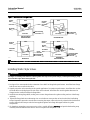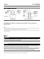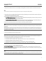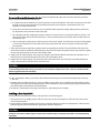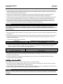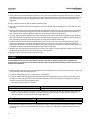
1
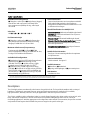
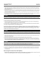
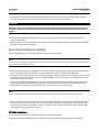
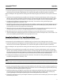
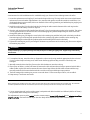
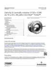
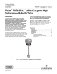
Instruction Manual A31A Valve D500240X012 October 2012 Fisherr POSI-SEAL™ A31A High Performance Butterfly Valve NPS 3 through 12 Contents Introduction . . . . . . . . . . . . . . . . . . . . . . . . . . . . . . . . . 1 Scope of Manual . . . . . . . . . . . . . . . . . . . . . . . . . . . . . 1 Specifications . . . . . . . . . . . . . . . . . . . . . . . . . . . . . . . 2 Description . . . . . . . . . . . . . . . . . . . . . . . . . . . . . . . . . 2 Educational Services . . . . . . . . . . . . . . . . . . . . . . . . . 3 Installation . . . . . . . . . . . . . . . . . . . . . . . . . . . . . . . . . . 3 Adjusting the Actuator Travel Stops or Travel . . . . . 3 Valve Orientation . . . . . . . . . . . . . . . . . . . . . . . . . . . . 5 Preparing for Installation . . . . . . . . . . . . . . . . . . . . . . 6 Installing Wafer-Style Valves . . . . . . . . . . . . . . . . . . . 9 Installing Single-Flange Valves . . . . . . . . . . . . . . . . 11 Maintenance . . . . . . . . . . . . . . . . . . . . . . . . . . . . . . . . 11 Replacing Packing . . . . . . . . . . . . . . . . . . . . . . . . . . 12 Removing the Valve from the Pipeline . . . . . . . . . . 13 Removing/Installing the Seal Ring . . . . . . . . . . . . . 14 PTFE Seal Installation . . . . . . . . . . . . . . . . . . . . 14 NOVEX Seal and Phoenix III Fire-Tested Seal Installation . . . . . . . . . . . . . . . . . . . . . . 15 Cryogenic Seal Installation . . . . . . . . . . . . . . . . 16 Anti-Blowout Protection, Packing, Valve Shaft(s), Disk, and Bearing Maintenance . . . . . . . . . . . . . 18 Removal . . . . . . . . . . . . . . . . . . . . . . . . . . . . . . . 18 Installing a One-Piece Shaft . . . . . . . . . . . . . . . 20 Installing a Two-Piece Shaft . . . . . . . . . . . . . . . 21 Installing the Gasket Retainer . . . . . . . . . . . . . 23 Figure 1. Typical Fisher A31A Valve W5811-1 W5812-1 Parts Ordering . . . . . . . . . . . . . . . . . . . . . . . . . . . . . . . 23 Parts List . . . . . . . . . . . . . . . . . . . . . . . . . . . . . . . . . . 23 Introduction Scope of Manual This instruction manual provides installation, maintenance, and parts ordering information for the Fisher POSI-SEAL A31A high-performance butterfly valves. Figure 1 shows typical A31A valves. For information regarding actuators and accessories, refer to separate instruction manuals. Do not install, operate, or maintain A31A valves without being fully trained and qualified in valve, actuator, and accessory installation, operation, and maintenance. To avoid personal injury or property damage, it is important to carefully read, understand, and follow all the contents of this manual, including all safety cautions and warnings. If you have any questions about these instructions, contact your Emerson Process Management sales office before proceeding. www.Fisher.com Instruction Manual A31A Valve October 2012 D500240X012 Table 1. Specifications Available Valve Configurations J Flangeless, wafer-style or J single-flange (lugged) control valve with a one-piece valve body and a two-component seal/backup O-ring, and a keyed drive shaft Valve Sizes NPS J 3, J 4, J 6, J 8, J 10, J 12 End Connection Style J Flangeless, wafer-style or J single flange valve body designed to fit between raised-face mating flanges per ASME B16.5 CL150 or CL300 Maximum Inlet Pressure/Temperature(4) Consistent with ASME J CL150 and J CL300 pressure/temperature ratings per ASME B16.34. Also, see figure 2 for additional information. Available Seal Configurations J Standard soft seal ring (PTFE) with fluorocarbon or EPR backup ring, J NOVEX seal ring, CL150, (S31600, 316 SST)(1) J NOVEX seal ring, CL300, standard pressure rating (S31600, 316 SST)(1) J NOVEX seal ring, CL300, high pressure rating (S21800), J Phoenix III fire-tested seal ring (S31600, 316 SST) with resilient insert (PTFE) and backup ring (fluorocarbon), or J cryogenic seal ring (CTFE) with optional backup ring (aluminum) Valve Classification Face-to-face dimensions are in compliance with MSS SP68 and API 609 standards; valve bodies are designed for installation between ASME B16.5 CL150 or 300 raised-face flanges Shutoff Classification. Per ANSI/FCI 70-2 Standard Soft Seal: Bidirectional bubble-tight shutoff NOVEX Seal: Unidirectional shutoff Class V (reverse flow direction only) Phoenix III Seal: Bidirectional bubble-tight shutoff Phoenix III Seal for Fire-Tested Applications: Consult your Emerson Process Management sales office for fire tested performance Cryogenic seal applications: Consult your Emerson Process Management sales office Installed Valve Orientation See figure 3 for orientation guidelines for optimum seal performance Valve In-Line Position Shaft horizontal. See figure 5 Available Actuators J Handlever, J handwheel, J spring-and-diaphragm, or J pneumatic piston Disk Rotation Clockwise to close 1. For specific information about materials of construction, contact your nearest Emerson Process Management sales office. 2. The pressure/temperature limits in this manual, and any applicable code or standard limitation, should not be exceeded. Description The A31A high-performance butterfly valve features a keyed drive shaft. The keyed shaft combines with a variety of handlevers, handwheels, pneumatic piston or spring-and-diaphragm actuators to make the A31A a reliable, high-performance, butterfly valve for a variety of applications in the various process industries. The A31A is available in either a flangeless (wafer) or a single-flange (lugged) valve design, with a variety of seal, valve body, and internal components. The A31A valve features a dynamic sealing design that is used in a variety of demanding applications. With the appropriate seal configuration and materials of construction, the pressure-assisted seal provides shutoff against the full ASME class pressure range for the specific valve type. 2 Instruction Manual D500240X012 A31A Valve October 2012 Educational Services For information on available courses for the Fisher POSI-SEAL A31 NPS 3 through 12 butterfly valve, as well as a variety of other products, contact: Emerson Process Management Educational Services, Registration P.O. Box 190; 301 S. 1st Ave. Marshalltown, IA 50158-2823 Phone: 800-338-8158 or Phone: 641-754-3771 FAX: 641-754-3431 e-mail: [email protected] Installation WARNING Always wear protective gloves, clothing, and eyewear when performing any installation operations to avoid personal injury. To avoid personal injury or property damage resulting from the sudden release of pressure, do not install the valve assembly where service conditions could exceed the limits given in this manual or on appropriate nameplates. Use pressure-relieving devices as required by government or accepted industry codes and good engineering practices. Check with your process or safety engineer for any additional measures that must be taken to protect against process media. If installing into an existing application, also refer to the WARNING at the beginning of the Maintenance section in this instruction manual. CAUTION The valve configuration and construction materials are selected to meet particular pressure, temperature, pressure drop, and controlled fluid conditions. Because pressure drop and temperature range capabilities limit some combinations of materials, do not apply any other conditions to the valve without first contacting your Emerson Process Management sales office. The maximum allowable inlet pressures for A31A valves are consistent with the applicable pressure/ temperature ratings except where limited by material capabilities shown in figure 2 and table 2. Adjusting the Actuator Travel Stops WARNING The edges of a rotating valve disk have a shearing effect that may result in personal injury. To avoid personal injury, keep clear of the disk edges when rotating the disk. 3 Instruction Manual A31A Valve October 2012 D500240X012 CAUTION When using an actuator, the actuator travel stops or the actuator travel (for actuators without adjustable stops) must be adjusted so that the disk stop in the valve body does not absorb the output of the actuator. Failure to limit actuator travel as described in the next step can result in damage to the valve shafts or other valve parts. 1. Locate the actuator travel stop that establishes the closed position of the valve disk. When adjusting the travel stop or travel, make sure that the disk is from 0.001 to 0.030 inch (0.03 to 0.76 mm) away from the internal stop in the valve body. This adjustment is necessary to be certain that the actuator output torque is fully absorbed by the actuator travel stop or by the actuator. The internal travel stop in the valve body should not absorb any of the actuator torque. 2. Before installing the valve/actuator assembly in the process line, cycle the valve several times to be sure the valve disk returns to the proper position. Table 2. Material Temperature Ratings COMPONENT, ASME CLASS, MATERIAL OF CONSTRUCTION TEMPERATURE RANGE _F Seal Ring _C See Figure 2 Backup Ring Soft Seal Fluorocarbon EPR Nitrile PTFE Chloroprene Phoenix III Seal Fluorocarbon EPR Nitrile Chloroprene Cryogenic Seal Aluminum (Optional) -20 to 400 -65 to 360 -20 to 200 -100 to 400 -45 to 300 -40 to 500 -80 to 400 -40 to 300 -65 to 300 -425 to 400 -29 to 204 -54 to 182 -29 to 93 -73 to 204 -43 to 149 -40 to 260 -62 to 204 -40 to 149 -59 to 149 -254 to 204 Shaft Packing(1) PTFE Graphite In Oxidizing Media In Inert or Reducing Media -425 to 450 -425 to 1000 -425 to 1500 -254 to 232 -254 to 538 -254 to 816 -100 to 800 -320 to 800 -425 to 900 -425 to 1300 -320 to 1100 -73 to 427 -195 to 427 -254 to 482 -254 to 704 -196 to 593 -100 to 500 -425 to 1500 -425 to 325 -425 to 500 -73 to 260 -254 to 816 -254 to 163 -196 to 260 -425 to 1000 -325 to 1500 -254 to 538 -198 to 816 Shaft(2) 17-4PH H1025 17-4PH H1150M N05500 N07718 S20910 Bearings PEEK(3) (standard) 316 SST PTFE Composition Bronze Disk Hardfacing Electroless Nickel Plating or hard chrome coating CoCr-A(4) (Alloy 6) 1. These low temperature limits apply to the flowing media. Valve extensions provided for cryogenic service maintain higher temperatures at the packing box. 2. Shaft material may affect the valve pressure rating. Consult your Emerson Process Management sales office. 3. PEEK stands for PolyEtherEtherKetone 4. CoCr-A hardfacing degrades shutoff performance of the seal. Consult your Emerson Process Management sales office. 4 Instruction Manual A31A Valve D500240X012 October 2012 Valve Orientation Note The NPS 10 through 12 CL150 valves and NPS 8 through 12 CL300 valves have a two-piece shaft. The shaft with the keyed end is called the drive shaft. The shaft opposite the drive shaft is called the follower shaft. The NPS 3 through 8 CL150 valves and NPS 3 through 6 CL300 valves have a one-piece shaft. This one-piece shaft is keyed and is called the drive shaft. Whenever possible, install the valve with the shaft in the horizontal position as shown in figure 5. Horizontal installation can enhance valve performance because process fluid flow will sweep entrained solids from valve surfaces, preventing particle buildup on the seal. Also, installation of the valve with the shaft horizontal will extend bearing life because entrained solids will be less likely to penetrate the bearings. Table 3. Valve Body Data, CL150 SHAFT DIAMETER AT YOKE BEARING FACE-TO-FACE DIMENSION(1) mm MINIMUM I.D.(2) 3 14.3 47.6 71.6 8.6 9.5 4 17.5 54.0 93.7 13 15 6 23.8 57.2 147.3 20 22 8 23.8 63.5 195.6 28 30 10 28.5 71.4 254.0 33 43 12 31.8 81.0 298.7 48 64 SHAFT DIAMETER AT YOKE BEARING FACE-TO-FACE DIMENSION(1) Inches MINIMUM I.D.(2) 3 9/16 1-7/8 2.82 19 21 4 11/16 2-1/8 3.69 28 32 6 15/16 2-1/4 5.80 45 49 8 15/16 2-1/2 7.70 61 67 10 1-1/8 2-13/16 10.00 73 95 12 1-1/4 3-3/16 11.76 105 141 VALVE SIZE, NPS VALVE SIZE, NPS APPROXIMATE WEIGHT, KILOGRAMS Wafer Single Flange APPROXIMATE WEIGHT, POUNDS Wafer Single Flange 1. Face-to-face dimensions are in compliance with MSS SP68 and API 609 specifications. 2. Minimum I.D. is the minimum pipe or flange I.D. required for disk swing clearance. The A31A valve is designed for installation with the shaft(s) in any orientation around the pipeline: horizontal, vertical, or at an intermediate angle. However, when installing the valve in certain services, follow the recommendations below, which are based on application experience: D In certain services (process fluids with high concentrations of entrained solids, abrasive slurries, polymerizing media, or large diameter valves with high flow rates), installing the valve with the shaft horizontal to the pipeline and downstream of the seal will enhance valve performance. D Install a valve supplied for uni-directional shutoff with the high pressure side in the direction noted on the valve body. A flow tag with an arrow is provided for proper installation. If you have questions about proper valve orientation in a specific application, contact your Emerson Process Management sales office. 5 Instruction Manual A31A Valve October 2012 D500240X012 Table 4. Valve Body Data, CL300 SHAFT DIAMETER AT YOKE BEARING FACE-TO-FACE DIMENSION(1) mm MINIMUM I.D.(2) 3 14.3 47.6 71.6 9.1 10 4 17.5 54.0 93.7 13 14 6 23.8 58.7 147.3 20 25 8 31.8 73.0 186.2 30 41 10 41.3 84.1 231.1 61 75 12 47.6 92.1 281.7 78 107 SHAFT DIAMETER AT YOKE BEARING FACE-TO-FACE DIMENSION(1) Inches MINIMUM I.D.(2) 3 9/16 1-7/8 2.82 20 23 4 11/16 2-1/8 3.69 28 31 6 15/16 2-5/16 5.80 44 54 8 1-1/4 2-7/8 7.33 67 91 10 1-5/8 3-5/16 9.10 134 166 12 1-7/8 3-5/8 11.09 171 235 VALVE SIZE, NPS VALVE SIZE, NPS APPROXIMATE WEIGHT, KILOGRAMS Wafer Single Flange APPROXIMATE WEIGHT, POUNDS Wafer Single Flange 1. Face-to-face dimensions are in compliance with MSS SP68 and API 609 specifications. 2. Minimum I.D. is the minimum pipe or flange I.D. required for disk swing clearance. Preparing for Installation CAUTION To avoid damage to the valve disk during installation, the valve must be in the fully-closed position. If the A31A valve is equipped with a fail-open actuator, remove the actuator before installing the valve/actuator assembly or cycle the valve into the fully closed position. Then, take appropriate steps to ensure that the actuator does not cause the valve to open during installation. 1. The A31A valve is normally shipped as part of an assembly with an actuator and other accessories such as a valve positioner. If the valve and actuator have been purchased separately or if the actuator has been removed for maintenance, properly mount the actuator and adjust valve/actuator travel and all travel stops before inserting the valve into the line. Follow the instructions in this manual for adjusting travel stops. Also, refer to a separate actuator instruction manual for detailed actuator mounting and adjustment procedures. 2. If not previously removed, remove the protective end covers from the valve and inspect the valve body to be certain that it is free of foreign material. Also, be certain that adjacent pipelines are free of any foreign material, such as pipe scale or welding slag that could damage the valve seating surfaces. CAUTION The A31A valve is designed for use with the appropriate piping schedule for the specified ASME class. Minimum inside diameters for flanges or pipe mating with valves are shown in tables 3 and 4. Be certain to align the valve accurately to avoid contact between the disk and the flanges. Improper alignment or insufficient space for disk rotation could result in damage to the disk. 3. Select the appropriate gaskets for the application. Flat sheet, spiral wound, or other gasket types, made to ASME B16.5 group or user's standard, can be used on the valves depending on the service conditions of the application. 4. Refer to table 5 for the quantity and size of flange bolts required. 6 Instruction Manual A31A Valve D500240X012 October 2012 Figure 2. Maximum Pressure/Temperature Ratings OPERATING TEMPERATURE, _C OPERATING TEMPERATURE, _C OPERATING TEMPERATURE, _F OPERATING TEMPERATURE, _F CL150, SOFT SEAL CL300, SOFT SEAL OPERATING TEMPERATURE, _C S31600 SST OPERATING TEMPERATURE, _F CL150, NOVEX SEAL OPERATING TEMPERATURE, _C S21800 S31600 SST B2335-2 OPERATING TEMPERATURE, _F CL300, NOVEX SEAL NOTE 1 BECAUSE OF POTENTIAL EROSIVE EFFECTS AND PREMATURE SEAL FAILURE THAT CAN OCCUR, THROTTLING PTFE SEALS AT DIFFERENTIAL PRESSURES GREATER THAN 300 PSID AT DISC ANGLES LESS THAN 20 DEGREES OPEN IS NOT RECOMMENDED. 2 TEMPERATURE LIMITATIONS DO NOT ACCOUNT FOR THE ADDITIONAL LIMITATIONS IMPOSED BY THE BACKUP RING USED WITH THIS SEAL TO DETERMINE THE EFFECTIVE TEMPERATURE LIMITATION OF THE APPROPRIATE SEAL/BACKUP RING COMBINATION, REFER TO TABLE 3. 7 Instruction Manual A31A Valve October 2012 D500240X012 Figure 2. Maximum Pressure/Temperature Ratings (continued) OPERATING TEMPERATURE, _C OPERATING TEMPERATURE, _F CL150, PHOENIX III SEAL OPERATING TEMPERATURE, _C OPERATING TEMPERATURE, _F CL300, PHOENIX III SEAL OPERATING TEMPERATURE, _C OPERATING TEMPERATURE, _C CTFE CTFE S21800 B2336-1 OPERATING TEMPERATURE, _F CL150, CRYOGENIC SEAL OPERATING TEMPERATURE, _F CL300, CRYOGENIC SEAL NOTE 2 TEMPERATURE LIMITATIONS DO NOT ACCOUNT FOR THE ADDITIONAL LIMITATIONS IMPOSED BY THE BACKUP RING USED WITH THIS SEAL TO DETERMINE THE EFFECTIVE TEMPERATURE LIMITATION OF THE APPROPRIATE SEAL/BACKUP RING COMBINATION, REFER TO TABLE 3. 8 Instruction Manual A31A Valve D500240X012 October 2012 Figure 3. Available Seal Configurations BACKUP RING BODY SEAL RING T-SLOT GRAPHITE GASKET RETAINING RING RETAINING RING VALVE DISK HIGH PRESSURE AT SHUTOFF SOFT SEAL WITH BACKUP O-RING GRAPHITE GASKET CRYOGENIC SEAL RING VALVE DISK HIGH PRESSURE AT SHUTOFF CRYOGENIC SEAL GRAPHITE GASKET BODY BODY BACKUP RING RETAINING RING METAL SEAL RING RETAINING RING VALVE DISK B2334-1 BODY NOVEX SEAL RING HIGH PRESSURE AT SHUTOFF NOVEX SEAL VALVE DISK RESILIENT INSERT HIGH PRESSURE AT SHUTOFF PHOENIX III FIRE-TESTED SEAL NOTE 1 FOR OPTIMUM SEAL PERFORMANCE, THE PREFERRED VALVE ORIENTATION AT SHUTOFF IS WITH THE RETAINING RING DOWNSTREAM FROM THE HIGH PRESSURE SIDE OF THE VALVE. Installing Wafer-Style Valves WARNING The edges of a rotating valve disk have a shearing effect that may result in personal injury. To avoid personal injury, keep clear of the disk edges when rotating the disk. 1. See figure 5 for recommended valve orientation. See table 5 for flange bolt specifications. Install the lower flange bolts first to form a cradle for the valve. 2. Properly orient the valve according to the specific application. For optimum performance, install the valve so that the shaft will be on the high pressure side of the valve at shutoff. Install the valve and the gaskets between the flanges into the cradle formed by the flange bolts. 3. Install the remaining flange bolts, making sure to center the gaskets on the gasket sealing surfaces of the flange and body. 4. Tighten the flange bolts in an alternating criss-cross fashion to a torque value of one-fourth of the final bolting torque. Repeat this procedure several times increasing the torque value each time by a fourth of the final desired torque. When the final torque value has been applied, tighten each flange bolt again to allow for gasket compression. 5. For hazardous atmosphere or oxygen service valves, read the following Warning, and provide the bonding strap assembly mentioned below if the valve is used in an explosive atmosphere. 9 Instruction Manual A31A Valve October 2012 D500240X012 Figure 4. Optional Shaft-to-Valve Body Bonding Strap Assembly ACTUATOR VALVE BODY 37A6528-A A3143-2 A VIEW A-A A Table 5. Hex Head Screw, Stud Bolt and Cap Screw Data(1) VALVE SIZE, NPS NUMBER CL150 SIZE DIA. INCH & THREAD CL300 CL150 CL300 LENGTH, INCH CL150 CL300 Single-Flange Style with Stud Bolts 3 4 8 5/8-11 3/4-10 5-3/4 6 4 8 8 5/8-11 3/4-10 6 6-1/2 6 8 12 3/4-10 3/4-10 6-1/2 7-1/2 8 8 12 3/4-10 7/8-9 7 9 10 12 16 7/8-9 1-8 8 10 12 12 16 7/8-9 1-1/8-8 8-1/2 11 Wafer-Style with Cap Screws 3 8 16 5/8-11 3/4-10 1-7/8 2 4 16 16 5/8-11 3/4-10 2 2-1/4 6 16 24 3/4-10 3/4-10 2 2-1/2 8 16 24 3/4-10 7/8-9 2-1/4 3 10 24 32 7/8-9 1-8 2-1/2 3 12 24 32 7/8-9 1-1/8-8 2-3/4 3-3/8 1. Thread engagement in accordance with ASME B31.3 “Chemical Plant and Petroleum Refinery Piping”. WARNING The valve drive shaft is not necessarily grounded to the pipeline when installed. Personal injury or property damage could result, if the process fluid or the atmosphere around the valve is flammable, from an explosion caused by a discharge of static electricity from the valve components. If the valve is installed in a hazardous area, electrically bond the drive shaft to the valve. Note The packing is composed of all conductive packing rings (graphite ribbon packing) to electrically bond the shaft to the valve for hazardous area service or non-conductive PTFE packing rings. For oxygen service applications, provide alternate shaft-to-valve body bonding according to the following step. 10 Instruction Manual A31A Valve D500240X012 October 2012 6. Attach the bonding strap assembly (key 131, figure 6) to the shaft with the clamp (key 130, figure 6). 7. Connect the other end of the bonding strap assembly to the valve flange cap screws. 8. For more information, refer to the Packing Maintenance section below. Installing Single-Flange Valves WARNING The edges of a rotating valve disk have a shearing effect that may result in personal injury. To avoid personal injury, keep clear of the disk edges when rotating the disk. 1. See figure 5 for recommended valve orientation. See table 5 for hex head cap screw specifications. 2. Properly orient the valve according to the specific application. For optimum performance, install the valve for reverse flow. 3. Position the valve between the flanges. Be sure to leave enough room for the flange gaskets. Install the lower flange bolts. 4. Select the appropriate gaskets for the application. Flat sheet, spiral wound, or other gasket types, made to the ASME B16.5 group standard or user's standard, can be used on the valve depending on the service conditions of the application. Install the gaskets and align the valve and the gaskets. 5. Install the remaining bolts. 6. Tighten the flange bolts in an alternating criss-cross fashion to a torque value of one-fourth of the final bolting torque. Repeat this procedure several times increasing the torque value each time by a fourth of the final desired torque. When you get to the final torque value, tighten each flange bolt again to allow for gasket compression. Table 6. Torque Values for Fasteners FASTENER NOMINAL SIZE #10 Retaining Ring Screws 1/4 5/16 3/8 7/16 1/2 9/16 5/8 LbfSin 41 100 7/8 1 1-1/8 220 400 53 83 119 166 296 480 720 1000 161 225 401 651 976 1356 NSm 4.6 11 25 45 72 112 LbfSin Gasket Retaining Bolts 3/4 LbfSft 35 81 LbfSft 167 295 39 59 86 119 210 330 480 617 117 161 286 447 651 837 NSm 4.0 9.2 19 33 53 80 Note: These values are based upon standard materials, S66286/N07718 screws and ASTM A193GRB6 bolts. For other special fastener materials, please contact your Emerson Process Manage ment sales office. Maintenance WARNING Avoid personal injury from sudden release of process pressure. Before performing any maintenance operations: D Do not remove the actuator from the valve while the valve is still pressurized. D Disconnect any operating lines providing air pressure, electric power, or a control signal to the actuator. Be sure the actuator cannot suddenly open or close the valve. 11 A31A Valve Instruction Manual October 2012 D500240X012 D Use bypass valves or completely shut off the process to isolate the valve from process pressure. Relieve process pressure on both sides of the valve. Drain the process media from either side of the valve. D Vent the power actuator loading pressure and relieve any actuator spring precompression. D Use lock-out procedures to be sure that the above measures stay in effect while you work on the equipment. Replacing Packing The A31A valve is designed so the packing can be replaced without removing the valve from the process pipeline. Packing may be PTFE V-rings or graphite. If you are installing an ENVIRO-SEAL™ Packing System in an existing valve, follow the instructions in the ENVIRO-SEAL Rotary Packing Instruction Manual (D101643X012). To remove packing parts in a valve with the ENVIRO-SEAL packing system, follow the procedures for valves using ENVIRO-SEAL packing system in this section. Figure 5. Properly Installed Wafer Style Valve A5557 For valves with PTFE or graphite packing: Key numbers for the parts in this section may be found in figure 7. CAUTION Tighten the packing flange only enough to prevent shaft leakage. Excessive tightening will only accelerate wear of the packing and could produce higher torques on the valve. Usually, packing leakage can be eliminated by merely tightening the hex nuts (key 15) located above the packing flange while the valve is in the pipeline. However, if leakage continues, replace the packing. CAUTION Never use a wrench or pliers on the valve shaft. A damaged shaft could cut the packing and allow leakage. 12 Instruction Manual D500240X012 A31A Valve October 2012 1. Before loosening any parts, isolate the valve from the line pressure, release pressure from both sides of the valve body, and drain the process media from both sides of the valve. Then, remove the hex nuts (key 15) and lift off the packing flange (key 11). 2. Remove the hex jam nuts (key 17), anti-blowout flange (key 10) and the packing follower (key 12). Also remove the anti-blowout ring (key 16) using a needle-nose pliers. The packing (key 13) is now accessible. Refer to figure 6 for details of the blowout protection. 3. Use a packing extractor to remove packing. Insert the corkscrew-like end of the tool into the first piece of packing and pull firmly to remove the packing. Repeat this process until all packing has been removed. CAUTION Be careful when cleaning the packing box. Scratches to the shaft or inside diameter of packing bore might cause leakage. 4. Before installing new packing, clean the packing box. 5. Install new packing (key 13) one ring at a time, using the packing follower (key 12) as a driver. If using split-ring packing, stagger the splits in the rings to avoid creating a leak path. 6. Reinstall all parts. Tighten the packing flange nuts (key 15) as needed to stop leakage under operating conditions. For valves using the ENVIRO-SEAL packing system: Normally, the packing nuts should not require re-tightening. However, when servicing an ENVIRO-SEAL packing system, if the springs do not remain nearly flat, retighten the packing box nuts until the springs are almost completely compressed. If leakage continues, replace the packing components as described in the following procedures. Keys numbers in this section may be found in figure 7. CAUTION Be careful when cleaning the packing box. Scratches to the shaft or inside diameter of the packing bore may cause leakage. 1. Before loosening any parts on the valve, isolate the control valve from the line pressure and release pressure from both sides of the valve body. 2. Loosen the two packing hex nuts evenly to remove spring tension, then remove the nuts. 3. Remove the packing flange and spring stack. The spring stack is held in place by an O-ring on the packing flange. Remove the two hex jam nuts and remove the anti-blowout flange, packing flange, anti-blowout ring, packing box ring, anti-extrusion washer, packing set, and packing box ring. CAUTION The valve shaft surface condition is critical in making and maintaining a good seal. If the valve shaft surface is scratched, nicked, dented, or worn, replace the valve shaft before replacing the packing system components. 4. Inspect the existing valve shaft. If necessary, replace the valve shaft as described in the procedures in this section. 5. Install the new packing system components as described in the ENVIRO-SEAL Rotary Packing Instruction Manual (D101643X012). Removing the Valve from the Pipeline 1. Disconnect any operating lines providing air pressure, electric power, or a control signal to the actuator. Be sure the actuator cannot suddenly open the valve. Vent the power actuator loading pressure. 13 A31A Valve October 2012 Instruction Manual D500240X012 2. Use bypass valves or completely shut off the process to isolate the valve from process pressure. Relieve process pressure on both sides of the valve. Drain the process media from either side of the valve. CAUTION Damage to the valve disk, piping or pipe flanges can occur if the disk is not closed when the valve is being removed from the pipeline. If necessary, stroke the actuator to place the disk in the closed position while removing the valve from the pipeline. 3. Loosen the flange bolting that holds the valve. Make sure the valve cannot slip or twist while loosening and removing the bolting. 4. Make certain the valve disk is closed and remove the valve from the pipeline. Support the valve properly and move the valve to an appropriate work area. Removing/Installing the Seal Ring Unless otherwise indicated, key numbers and part names are listed in figure 8. Note For larger valves, it is possible to replace the seal ring (key 5) while the actuator is mounted to the valve and can be accomplished by cycling the valve to 90 degrees open. 1. After removing the valve from the pipeline, remove the manual or power actuator. Manually rotate the drive shaft (key 3) counterclockwise until the disk has moved a full 180 degrees away from the closed position. 2. Lay the valve flat on a work bench in a secure position with the retaining ring (key 18) and retaining ring screws (key 19) facing up. Properly secure the valve on a suitable worktable so it can not slip, twist, or fall during maintenance. Remove all retaining ring screws. 3. Remove the retaining ring by placing a socket head retaining ring screw from the retaining ring in each of the two retaining ring jacking screw holes. Slowly turn the screws until the retaining ring has been lifted from the valve body. Remove the retaining ring to expose the seal ring in the T-slot area of the valve body. Note The A31A valve is available with different seal designs and components. See figure 3 to identify the specific seal design. 4. Insert a regular screw driver or other similar tool under the top edge of the seal ring (key 5), and gently pry it out of the T-slot area in the valve body. Take care not to damage the seal ring or T-slot area of the valve body. After the seal ring has been removed, clean the T-slot area, retaining ring, and, if required, polish the disk thoroughly with fine steel wool or other appropriate material. PTFE Seal Installation Unless otherwise indicated, key numbers and part names are listed in figure 8. A maintenance kit with installation tools is available through your Emerson Process Management sales office. 14 Instruction Manual D500240X012 A31A Valve October 2012 1. Locate the replacement seal ring (key 5) and note the shape of the ring. The ring is wider across one edge diameter and narrower across the other edge diameter. Also, note the wide groove around the outside circumference. Before installing the seal ring into the valve body, place the backup ring (key 6) into the wide, outer groove of the seal ring. 2. Install the seal ring and backup ring assembly in the valve body. The wider outside diameter of the seal ring, goes into the T-slot area of the valve body as shown in figure 6. Start the edge with the wider diameter into the T-slot of the valve body using a blunt-end screwdriver. If a maintenance kit is available, use the seal ring installation tools. 3. Carefully tuck the backup ring downward into the valve body T-slot until the seal ring and backup ring are completely entrapped in the valve body T-slot. 4. Completely seat the seal ring in the valve body T-slot. Re-install the retaining ring (key 18) and retaining ring screws (key 19). Tighten the screws just enough to eliminate any movement of the retaining ring. Using a blunt-end tool, carefully tuck the lip of the seal ring under the retaining ring. 5. When the seal ring is under the lip of the retaining ring, tighten the screws according to standard procedures. Do not fully torque screws at this time. Final tightening of the screws is accomplished in step 7. 6. Manually rotate the drive shaft (key 3) clockwise 180 degrees to return the disk (key 2) to its closed position. 7. The final seating of the retaining ring cap screws can now be done. For the screw torque values, refer to table 6. The seal is now completely installed and the valve may be placed in service. Novex Seal and Phoenix III Fire-Tested Seal Installation Unless otherwise indicated, key numbers and part names are listed in figure 8. A maintenance kit with installation tools is available through your Emerson Process Management sales office. 1. Locate the replacement seal ring (key 5) and note the shape of the ring. The ring is wider across one edge diameter and narrower across the other edge diameter. Also, note the wide groove around the outside circumference. Before installing the seal ring into the valve body, place the backup ring (key 6) into the wide, outer groove of the seal ring. 2. Install the seal ring and backup ring assembly in the valve body. The wider outside diameter of the seal ring goes into the T-slot area of the valve body as shown in figure 6. Start the edge with the wider diameter into the T-slot of the valve body using a blunt-end screwdriver. If a maintenance kit is available, use the seal ring installation tools. Do not use the screwdriver or seal ring tool directly on the metal seat. Use the tool only on the backup ring. 3. Carefully tuck the backup ring downward into the valve body T-slot until the seal ring and backup ring are completely entrapped in the valve body T-slot. Note On larger valves, it may be more efficient to have someone hold down the seal ring while you push the backup ring into the T-slot. 4. Once the seal ring and backup ring have been fully installed into the valve body T-slot, the retaining ring gasket can be installed. This gasket is a thin graphite material. Use extreme care to avoid damaging the gasket while punching one initial screw hole through the gasket for alignment. 5. Install the retaining ring, and align the screw holes in the retaining ring with the holes in the valve body. Install the first retaining ring screw through the punched hole in the retaining ring gasket. Install the other retaining ring screws by pushing them through the graphite gasket and threading them into the valve body. 6. Tighten the retaining ring screws just enough to eliminate any movement of the retaining ring. Do not over-tighten the retaining ring screws. 15 Instruction Manual A31A Valve October 2012 D500240X012 Figure 6. Typical Seal Installation LARGEST OUTSIDE DIAMETER (KEY 5) A5251-1* WARNING Avoid personal injury or property damage caused by the impact of a falling or tipping valve. Support large valves during maintenance. 7. To complete this step, stand the valve up. Support the valve securely using methods appropriate for the valve size. If a vise or other clamps are being used, make certain the flange gasket sealing area of the valve body is not damaged. 8. Manually rotate the drive shaft (key 3) to turn the disk clockwise to meet the seal ring. 9. Place a piece of rubber, or other soft material, between the disk and internal travel stop to protect the disk. With a rubber mallet, tap the disk until it contacts the internal travel stop. When the disk makes contact with the stop, manually rotate the disk counterclockwise back out of the seal ring to a 90-degree open position. 10. The final seating of the retaining ring screws can now be done. For the screw torque values, refer to table 6. 11. Repeat steps 8 and 9 two more times. Note When attaching the actuator to the valve, make sure the valve disk is not in contact with the internal travel stop. The valve disk should be positioned from 0.001 to 0.030 inch (0.03 to 0.76 mm) away from the internal stop in the valve body. 12. Use an appropriate tool (such as a feeler gauge) and position the disk from 0.001 to 0.030 inch (0.03 to 0.76 mm) away from the internal stop in the valve body. This adjustment is necessary to be certain that the actuator output torque is fully absorbed by the actuator travel stop or by the actuator. The internal travel stop in the valve body should not absorb any of the actuator torque. Cryogenic Seal Installation Unless otherwise indicated, key numbers and part names are listed in figure 8. 16 Instruction Manual D500240X012 A31A Valve October 2012 A maintenance kit with installation tools is available through your Emerson Process Management sales office. 1. Locate the replacement seal ring (key 5) and note the shape of the ring. The ring is wider across one edge diameter and narrower across the other edge diameter. Also, note the wide groove around the outside circumference. If an aluminum backup ring is provided, fit this over the back of the seal ring (matching seal and backup ring angles) prior to installation in the valve. 2. Install the seal ring (key 5) in the valve body by first placing the wider outside diameter of the seal ring into the T-slot area of the valve body as shown in figure 6. 3. Once the seal ring has been fully installed into the body T-slot, the retaining ring gasket can be installed. This gasket is a thin graphite material. Use extreme care to avoid damaging the gasket while punching one initial screw hole through the gasket for alignment. 4. Install the retaining ring, and align the screw holes in the retaining ring with the holes in the valve body. Install the first retaining ring screw through the punched hole in the retaining ring gasket. Install the other retaining ring screws by pushing them through the graphite gasket and threading them into the valve body. 5. Tighten the retaining ring screws just enough to eliminate any movement of the retaining ring. Do not over-tighten the retaining ring screws. WARNING Avoid personal injury or property damage caused by the impact of a falling or tipping valve. Support large valves during maintenance. 6. To complete this step, stand the valve up. Support the valve securely using methods appropriate for the valve size. If a vise or other clamps are being used, make certain the flange gasket sealing area of the valve body is not damaged. 7. Manually rotate the drive shaft (key 3) to turn the disk clockwise to meet the seal ring. 8. Place a piece of rubber, or other soft material, between the disk and internal travel stop to protect the disk. With a rubber mallet, tap the disk until it contacts the internal travel stop. When the disk makes contact with the stop, manually rotate the disk counterclockwise back out of the seal ring to a 90-degree open position. 9. The final seating of the retaining ring screws can now be done. For the screw torque values, refer to table 6. 10. Repeat steps 7 and 8 two more times. Note When attaching the actuator to the valve, make sure the valve disk is not in contact with the internal travel stop. The valve disk should be positioned from 0.001 to 0.030 inch (0.03 to 0.76 mm) away from the internal stop in the valve body. 11. Use an appropriate tool (such as a feeler gauge) and position the disk from 0.001 to 0.030 inch (0.03 to 0.76 mm) away from the internal stop in the valve body. This adjustment is necessary to be certain that the actuator output torque is fully absorbed by the actuator travel stop or by the actuator. The internal travel stop in the valve body should not absorb any of the actuator torque. 17 Instruction Manual A31A Valve October 2012 D500240X012 Figure 7. Anti-Blowout Protection Detail PACKING FLANGE (KEY 11) ANTI-BLOWOUT FLANGE (KEY 10) HEX JAM NUT (KEY 17) PACKING FLANGE (KEY 11) PACKING FOLLOWER (KEY 12) TYPICAL PACKING (KEY 13) VALVE BODY C0766 STUD (KEY 14) AND HEX NUT (KEY 15) EXTERNAL DETAILS ANTI-BLOWOUT RING (KEY 16) ANTI-BLOWOUT FLANGE (KEY 10) VALVE BODY CUTAWAY, NPS 3 THROUGH 12 Anti-Blowout Protection, Packing, Valve Shaft(s), Disk, and Bearing Maintenance Note The NPS 10 through 12 CL150 valves and NPS 8 through 12 CL300 valves have a two-piece shaft. The shaft with the keyed end is called the drive shaft. The shaft opposite the drive shaft is called the follower shaft. The NPS 3 through 8 CL150 valves and NPS 3 through 6 CL300 valves have a one-piece shaft. This one-piece shaft is keyed and is called the drive shaft. Removal WARNING The edges of a rotating valve disk (key 2) have a shearing effect that might result in personal injury. To avoid personal injury, keep clear of the disk edges when rotating the disk. CAUTION When removing the actuator from the valve, do not use a hammer or similar tool to drive the lever off the valve shaft. Driving the lever or actuator off the valve shaft could damage the valve internal parts. If necessary, use a wheel puller to remove the lever or actuator from the valve shaft. It is okay to tap the wheel puller screw lightly to loosen the lever or actuator, but hitting the screw with excessive force could also damage internal valve parts. Never use a wrench or pliers on the drive shaft. A damaged shaft could cut the packing and allow leakage. Unless otherwise indicated, key numbers and part names are listed in figure 8. 18 Instruction Manual D500240X012 A31A Valve October 2012 1. Remove the actuator and valve, as an assembly, from the pipeline, and then remove the actuator from the valve. Note It is not necessary to remove the retaining ring and seal ring when removing the shaft(s) and disk. 2. Secure the valve in an upright position. Rotate the disk (key 2) 180 degrees counterclockwise from the fully closed position by manually turning the drive shaft. 3. Removing the Anti-Blowout Protection (refer to figure 7): a. For PTFE or Graphite Packing: Remove the hex nuts and pull off the packing flange. Remove the hex jam nuts and the anti-blowout flange. Remove the packing follower. b. For ENVIRO-SEAL Packing System: Evenly loosen and remove the two packing hex nuts, the packing flange, the spring stack, the two hex jam nuts, the anti-blowout flange, and the packing follower. 4. Remove the anti-blowout ring from around the drive shaft using a needle nose pliers. Note NPS 3 through 12 valves (CL150 and 300) have a bearing stop (key 8, figure 8) pressed into the bearing bore immediately after the packing box. Do not attempt to remove the bearing stop which is found in the drive shaft bearing bore immediately after the packing box. The bearing stop is pressed into the bearing bore. If the bearing stop needs replacement, contact your Emerson Process Management sales office for more information. 5. Remove the packing from around the drive shaft. Note Different valves require slightly different procedures because different valve sizes/ pressure classes have different methods of connecting the disk and shaft(s). To identify the proper procedures, refer to the list below. D CL150, NPS 3 through 8: One-piece shaft with 1 taper key. D CL150, NPS 10 and 12: Two-piece shaft. 1 taper key in the drive shaft; 1 disk pin in the follower shaft. D CL300, NPS 3 through 6: One-piece shaft with 1 taper key. D CL300, NPS 8 and 10: Two-piece shaft. 1 taper key in the drive shaft; 1 disk pin in the follower shaft. D CL300, NPS 12: Two-piece shaft with 2 tangential pins in the drive shaft; 1 disk pin in the follower shaft. 6. Proceed as appropriate, using the following instructions. For valves with taper key(s), locate the taper key(s) (key 9, figure 8) which runs through the drive shaft boss on the back of the valve disk. Using a pin punch on the smaller end of the key, drive it out of the disk and shaft. Driving a taper key in the wrong direction will tighten it. Note Certain valve sizes may have a taper key that is arc spot welded in place. To remove the key, use a punch on the smaller end of the taper key and drive it out of the disk and shaft, breaking the weld. 19 A31A Valve October 2012 Instruction Manual D500240X012 For valves with tangential pins and/or disk pins, locate the tangential pins (key 26) in the drive shaft (key 3) and the disk pin (key 26) in the follower shaft (key 4). a. If a maintenance kit is available, use the pin extractor to remove the disk pins. Select the correct size pin extractor tip with screws of proper thread size to match the thread size in the disk pins. If a maintenance kit is not available, see steps c and d below. b. Screw the pin extractor tip into the pin as far as possible. With an upward, straight sliding motion, pull out the pin. Repeat the same procedure for the other pins. c. Use a threaded rod with an appropriate spacer and nut as an extractor tool. If using a threaded rod, choose a rod with threads that fit the inside thread of the pins. The rod should extend several inches above the disk when it is screwed into a pin. d. After screwing the rod into the pin, slide the spacer over the rod and pin. Thread the nut onto the rod and tighten it. As the nut is tightened, the nut will drive the spacer against the disk. The increasing force will draw the pin from the disk. 7. Valves with a two-piece shaft have a gasket retainer and gasket (keys 20 and 21) on the follower shaft side of the valve. Remove the hex head bolts and lockwashers (keys 23 and 22) from the gasket retainer and remove the gasket retainer and gasket to expose the end of the follower shaft. 8. Support the valve disk properly, and remove the follower shaft. Pull the follower shaft from the valve body. Use a shaft extractor screwed into the puller hole in the end of the follower shaft. 9. Support the valve disk properly, and remove the drive shaft. Pull out the drive shaft (key 3) by hand-pulling or by using a shaft extractor screwed into the end of the shaft. CAUTION To avoid damage to the disk, seal ring, and T-slot area, do not force the disk past the seal or T-slot area. Remove the disk from the opposite side of the valve body. 10. After removing the shaft(s), remove the disk and the thrust bearings. Do not force the disk past the seal ring or T-slot area. 11. Remove the journal bearings (key 7). Using a suitable punch or puller, drive or pull the journal bearing(s) into the valve body bore from the drive shaft bearing bore. Do not attempt to remove the bearing stop (key 8). Remove the journal bearing from the follower shaft bearing bore. 12. Inspect the valve body bore, bearings, bearing bores, and packing box for damage. Installing a One-Piece Shaft Unless otherwise indicated, key numbers and part names are listed in figure 8. 1. Secure the valve in an upright position. Allow for easy access to the valve body bore. Allow for easy access to the drive shaft bearing bore. 2. Inspect all parts removed from the valve for wear or damage. Replace any worn or damaged parts. Clean the valve body and all parts to be installed with an appropriate solvent or degreaser. CAUTION Premature valve failure and loss of process control may result if bearings are improperly installed or are damaged during installation. 20 Instruction Manual A31A Valve D500240X012 October 2012 3. Using caution to prevent damage to the bearing, insert one journal bearing (key 7) from the valve body bore into the drive shaft bearing bore until it hits the bearing stop (key 8). When properly installed, a portion of the journal bearing will extend into the valve body bore. 4. Insert one journal bearing from the valve body bore into the shaft bearing bore opposite the journal bearing installed in step 3. When correctly installed, this journal bearing will be flush with the valve body bore. 5. Install the valve disk by placing the disk into the valve body bore so the curved side of the disk passes through the end of the valve body that does not contain the T-slot. Align the shaft bore in the disk with the bearing bores. 6. Insert the drive shaft end opposite the keyed end into the valve body through the packing box. Push the shaft through the bearing stop. Taking care not to dislodge the journal bearing, push the shaft through the journal bearing and the valve disk and into the bore on the opposite side of the valve body. CAUTION To avoid damage to the taper key, tangential pins, disk pins, valve disk, or shaft(s) resulting from the application of excessive force, use appropriate care when driving the key or pins into the disk hub and shaft(s). Use the right tool. Do not use excessive force. 7. Be sure the taper key disk shaft joint is free of oil or grease. If necessary, remove any excess welding material from the taper key. 8. Align the taper key hole in the shaft with the holes in the shaft boss on the disk. Insert the taper key. Use a flat-end punch to drive the taper key until solid contact is felt. Measure the depth of the taper key head for a reference during the following steps. a. Drive the taper key in farther as follows: VALVE SIZE, NPS MINIMUM DEPTH TO DRIVE TAPER KEY AFTER INITIAL SOLID CONTACT CL150 and 300, NPS 3, 4, 6 valves, & NPS 8 CL150 valves 5 mm (0.188 INCHES) b. The disk shaft, and taper key assembly must be inspected to verify that the taper key spans the entire shaft flat width. If so, this procedure is complete. If not, the taper key must be driven in farther until this condition is satisfied. However, do not exceed the following depth limits: VALVE SIZE, NPS MINIMUM ALLOWABLE DEPTH TO DRIVE TAPER KEY AFTER INITIAL SOLID CONTACT NPS 3 and 4 CL150/300 7 mm (0.281 INCHES) NPS 6 CL300, and NPS 8 CL150 8 mm (0.312 INCHES) 9. After driving the taper key in place, arc spot weld the head of the taper key to the disk as shown in figure 8. For NPS 3, 4, and 6 valves, use an arc spot weld bead of 1/8-inch diameter. For NPS 8, 10, and 12 valves, use an arc spot weld bead of 3/16-inch diameter. 10. Install the packing as described in the Packing Replacement section or in the ENVIRO-SEAL Rotary Packing Instruction Manual (D101643X012). Installing a Two-Piece Shaft Unless otherwise indicated, key numbers and part names are listed in figure 8. 1. Secure the valve in an upright position. Allow for easy access to the valve body bore. Allow for easy access to the drive shaft bearing bore and the follower shaft bearing bore. 2. Inspect all parts removed from the valve for wear or damage. Replace any worn or damaged parts. Clean the valve body and all parts to be installed with an appropriate solvent or degreaser. CAUTION Premature valve failure and loss of process control may result if bearings are improperly installed or are damaged during installation. 21 Instruction Manual A31A Valve October 2012 D500240X012 3. Using caution to prevent damage to the bearings, insert the required number of journal bearings (key 7) from the valve body bore into the drive shaft bearing bore. When properly installed, one end of the journal bearing(s) will be flush with the interior end of the packing box, the other end of the journal bearing(s) will be flush with the valve body bore. The drive shaft thrust bearing (key 24) will be installed in step 5. 4. Insert one journal bearing from the valve body bore into the follower shaft bearing bore so it is flush with the valve body bore. 5. Insert the drive shaft into the valve body through the packing box. Push the drive shaft through the journal bearing. Hold the drive shaft thrust bearing (key 24) in the valve body bore against the opening of the drive shaft bearing bore. Push the drive shaft through the bearing bore just enough to hold the thrust bearing. 6. Insert the follower shaft through the bore in the valve body uncovered by removal of the gasket retainer. Hold the follower shaft thrust bearing (key 24) in the valve body bore against the opening of the follower shaft bearing bore. Push the follower shaft through the bearing bore just enough to hold the thrust bearing. 7. Install the valve disk. Place the flat side of the disk on a flat surface. Then, move the valve body from its upright position and suspend the valve body over the disk so the seal ring/T-slot area is facing up. Align the shaft bores through the disk with the drive shaft and follower shaft bores. Lower the valve body over the disk using caution not to dislodge or damage the thrust bearings placed on the ends of the shafts. 8. With the valve disk properly positioned in the valve body, push the drive shaft and follower shaft the rest of the way through the thrust bearings and into the shaft bores in the valve disk. 9. Align the holes in the shafts with the holes in the disk. CAUTION To avoid damage to the taper key, tangential pins, disk pins, valve disk, or shaft(s) resulting from the application of excessive force, use appropriate care when driving the key or pins into the disk hub and shaft(s). Use the correct tool, and do not use excessive force. 10. Before installing the taper key, be sure the taper key disk shaft joint is free of oil or grease. If necessary, remove any excess welding material from the taper key. 11. Install the appropriate taper key, tangential pins, and disk pins. 12. Install the taper key by aligning the taper key hole in the shaft with the holes in the shaft boss on the disk. Insert the taper key. Use a pin punch to drive the taper key until solid contact is felt. Measure the depth of the taper key head for a reference during the following steps. a. Drive the taper key in farther as follows: VALVE SIZE, NPS MINIMUM DEPTH TO DRIVE TAPER KEY AFTER INITIAL SOLID CONTACT NPS 8 CL300, NPS 10 and 12 CL150, & NPS 10 CL300 valves 6 mm (0.219 INCHES) b. The disk shaft, and taper key assembly must be inspected to verify that the taper key spans the entire shaft flat width. If so, this procedure is complete. If not, the taper key must be driven in farther until this condition is satisfied. However, do not exceed the following depth limits: VALVE SIZE, NPS MINIMUM ALLOWABLE DEPTH TO DRIVE TAPER KEY AFTER INITIAL SOLID CONTACT NPS 8 CL300, and NPS 10 and 12 CL150 10 mm (0.375 INCHES) NPS 10 CL300 11 mm (0.406 INCHES) 13. After driving the taper key in place, arc spot weld the head of the taper key to the disk as shown in figure 8. For NPS 10 and 12 valves, use an arc spot weld bead of 3/16-inch in diameter. packing box. Install the packing around the drive shaft. 22 Instruction Manual A31A Valve D500240X012 October 2012 14. Install the packing as described in the Packing Replacement section or in the ENVIRO-SEAL Rotary Packing Instruction Manual (D101643X012). Installing the Gasket Retainer Valves with a two-piece shaft use a gasket retainer and gasket to cover the follower shaft opening in the valve body. 1. Replace the gasket (key 21) and gasket retainer (key 20) over the end of the follower shaft. Use a new gasket. 2. Replace the four hex head bolts (key 23) and lockwashers (key 22) to hold the gasket retainer in place. 3. Be sure to center the gasket over the follower shaft bore before retightening the bolts. Tighten down the bolts evenly in a crossover or star pattern. Refer to table 6 for proper torque values. Parts Ordering When corresponding with your Emerson Process Management sales office about this equipment, always mention the valve serial number. When ordering replacement parts, also specify the key number, part name, desired material, using the Parts List table. WARNING Use only genuine Fisher replacement parts. Components that are not supplied by Emerson Process Management should not, under any circumstances, be used in any Fisher valve, because they may void your warranty, might adversely affect the performance of the valve, and could cause personal injury and property damage. Parts List Key 1 2 3 4 5 6 7 8 10 11 12 13 14 15 Description Valve body Disk Drive shaft Follower shaft Seal ring Backup ring Journal bearing Bearing stop Anti-blowout flange Packing flange Packing follower Packing Stud Hex nut Key 16 17 18 19 20 21 22 23 24 25 26 27 29 30 33 Description Anti-blowout ring Hex jam nut Retaining ring Retaining ring, screw Gasket retainer Gasket Lockwasher Hex head bolt Thrust bearing Key (for drive shaft) Tangential pin or disk pin Retaining ring gasket, graphite Nameplate (not shown) Drive screw (not shown) Flow direction arrow (not shown) 23 Instruction Manual A31A Valve October 2012 D500240X012 Figure 8. Fisher A31A NPS 3 through 12 Typical Assembly WELD LOCATION TAPER KEY SHAFT WELD LOCATION DISK A5947 MINIMUM TAPER KEY ENGAGEMENT MAXIMUM TAPER KEY ENGAGEMENT VIEW A TAPER KEY WELD LOCATION NPS 8 & 10 CL300 NPS 10 & 12 CL150 SEE VIEW A NPS 12 CL300 NPS 3 THROUGH 8 CL150 NPS 3 THROUGH 6 CL300 27291 27301 C0821 NPS 3 THROUGH 8 CL150 AND NPS 3 THROUGH 6 CL300 (WAFER STYLE SHOWN) NPS 8 THROUGH 12 CL300 NPS 10 AND 12 CL150 Neither Emerson, Emerson Process Management, nor any of their affiliated entities assumes responsibility for the selection, use or maintenance of any product. Responsibility for proper selection, use, and maintenance of any product remains solely with the purchaser and end user. Fisher, POSI-SEAL, and ENVIRO-SEAL are marks owned by one of the companies in the Emerson Process Management business unit of Emerson Electric Co. Emerson Process Management, Emerson, and the Emerson logo are trademarks and service marks of Emerson Electric Co. All other marks are the property of their respective owners. The contents of this publication are presented for informational purposes only, and while every effort has been made to ensure their accuracy, they are not to be construed as warranties or guarantees, express or implied, regarding the products or services described herein or their use or applicability. All sales are governed by our terms and conditions, which are available upon request. We reserve the right to modify or improve the designs or specifications of such products at any time without notice. Emerson Process Management Marshalltown, Iowa 50158 USA Sorocaba, 18087 Brazil Chatham, Kent ME4 4QZ UK Dubai, United Arab Emirates Singapore 128461 Singapore www.Fisher.com 24 E 1998, 2012 Fisher Controls International LLC. All rights reserved.