1
Cisco Content Engine 511 and 566
Hardware Installation Guide
Corporate Headquarters
Cisco Systems, Inc.
170 West Tasman Drive
San Jose, CA 95134-1706
USA
http://www.cisco.com
Tel: 408 526-4000
800 553-NETS (6387)
Fax: 408 526-4100
Text Part Number: OL-5756-01
THE SPECIFICATIONS AND INFORMATION REGARDING THE PRODUCTS IN THIS MANUAL ARE SUBJECT TO CHANGE WITHOUT
NOTICE. ALL STATEMENTS, INFORMATION, AND RECOMMENDATIONS IN THIS MANUAL ARE BELIEVED TO BE ACCURATE BUT
ARE PRESENTED WITHOUT WARRANTY OF ANY KIND, EXPRESS OR IMPLIED. USERS MUST TAKE FULL RESPONSIBILITY FOR
THEIR APPLICATION OF ANY PRODUCTS.
THE SOFTWARE LICENSE AND LIMITED WARRANTY FOR THE ACCOMPANYING PRODUCT ARE SET FORTH IN THE INFORMATION
PACKET THAT SHIPPED WITH THE PRODUCT AND ARE INCORPORATED HEREIN BY THIS REFERENCE. IF YOU ARE UNABLE TO
LOCATE THE SOFTWARE LICENSE OR LIMITED WARRANTY, CONTACT YOUR CISCO REPRESENTATIVE FOR A COPY.
The following information is for FCC compliance of Class A devices: This equipment has been tested and found to comply with the limits for a Class
A digital device, pursuant to part 15 of the FCC rules. These limits are designed to provide reasonable protection against harmful interference when
the equipment is operated in a commercial environment. This equipment generates, uses, and can radiate radio-frequency energy and, if not installed
and used in accordance with the instruction manual, may cause harmful interference to radio communications. Operation of this equipment in a
residential area is likely to cause harmful interference, in which case users will be required to correct the interference at their own expense.
The following information is for FCC compliance of Class B devices: The equipment described in this manual generates and may radiate
radio-frequency energy. If it is not installed in accordance with Cisco’s installation instructions, it may cause interference with radio and television
reception. This equipment has been tested and found to comply with the limits for a Class B digital device in accordance with the specifications in
part 15 of the FCC rules. These specifications are designed to provide reasonable protection against such interference in a residential installation.
However, there is no guarantee that interference will not occur in a particular installation.
Modifying the equipment without Cisco’s written authorization may result in the equipment no longer complying with FCC requirements for Class
A or Class B digital devices. In that event, your right to use the equipment may be limited by FCC regulations, and you may be required to correct
any interference to radio or television communications at your own expense.
You can determine whether your equipment is causing interference by turning it off. If the interference stops, it was probably caused by the Cisco
equipment or one of its peripheral devices. If the equipment causes interference to radio or television reception, try to correct the interference by
using one or more of the following measures:
• Turn the television or radio antenna until the interference stops.
• Move the equipment to one side or the other of the television or radio.
• Move the equipment farther away from the television or radio.
• Plug the equipment into an outlet that is on a different circuit from the television or radio. (That is, make certain the equipment and the television
or radio are on circuits controlled by different circuit breakers or fuses.)
Modifications to this product not authorized by Cisco Systems, Inc. could void the FCC approval and negate your authority to operate the product.
The Cisco implementation of TCP header compression is an adaptation of a program developed by the University of California, Berkeley (UCB) as
part of UCB’s public domain version of the UNIX operating system. All rights reserved. Copyright © 1981, Regents of the University of California.
NOTWITHSTANDING ANY OTHER WARRANTY HEREIN, ALL DOCUMENT FILES AND SOFTWARE OF THESE SUPPLIERS ARE
PROVIDED “AS IS” WITH ALL FAULTS. CISCO AND THE ABOVE-NAMED SUPPLIERS DISCLAIM ALL WARRANTIES, EXPRESSED
OR IMPLIED, INCLUDING, WITHOUT LIMITATION, THOSE OF MERCHANTABILITY, FITNESS FOR A PARTICULAR PURPOSE AND
NONINFRINGEMENT OR ARISING FROM A COURSE OF DEALING, USAGE, OR TRADE PRACTICE.
IN NO EVENT SHALL CISCO OR ITS SUPPLIERS BE LIABLE FOR ANY INDIRECT, SPECIAL, CONSEQUENTIAL, OR INCIDENTAL
DAMAGES, INCLUDING, WITHOUT LIMITATION, LOST PROFITS OR LOSS OR DAMAGE TO DATA ARISING OUT OF THE USE OR
INABILITY TO USE THIS MANUAL, EVEN IF CISCO OR ITS SUPPLIERS HAVE BEEN ADVISED OF THE POSSIBILITY OF
SUCH DAMAGES.
CCSP, the Cisco Square Bridge logo, Cisco Unity, Follow Me Browsing, FormShare, and StackWise are trademarks of Cisco Systems, Inc.; Changing
the Way We Work, Live, Play, and Learn, and iQuick Study are service marks of Cisco Systems, Inc.; and Aironet, ASIST, BPX, Catalyst, CCDA,
CCDP, CCIE, CCIP, CCNA, CCNP, Cisco, the Cisco Certified Internetwork Expert logo, Cisco IOS, Cisco Press, Cisco Systems, Cisco Systems
Capital, the Cisco Systems logo, Empowering the Internet Generation, Enterprise/Solver, EtherChannel, EtherFast, EtherSwitch, Fast Step,
GigaDrive, GigaStack, HomeLink, Internet Quotient, IOS, IP/TV, iQ Expertise, the iQ logo, iQ Net Readiness Scorecard, LightStream, Linksys,
MeetingPlace, MGX, the Networkers logo, Networking Academy, Network Registrar, Packet, PIX, Post-Routing, Pre-Routing, ProConnect,
RateMUX, Registrar, ScriptShare, SlideCast, SMARTnet, StrataView Plus, SwitchProbe, TeleRouter, The Fastest Way to Increase Your Internet
Quotient, TransPath, and VCO are registered trademarks of Cisco Systems, Inc. and/or its affiliates in the United States and certain other countries.
All other trademarks mentioned in this document or Website are the property of their respective owners. The use of the word partner does not imply
a partnership relationship between Cisco and any other company. (0406R)
Cisco Content Engine 511 and 566 Hardware Installation Guide
Copyright © 2004 Cisco Systems, Inc. All rights reserved.
CONTENTS
Preface ix
Document Objectives ix
Audience x
Document Organization x
Document Conventions xi
Obtaining Documentation xxi
Cisco.com xxi
Ordering Documentation xxi
Documentation Feedback xxii
Obtaining Technical Assistance xxii
Cisco Technical Support Website xxii
Submitting a Service Request xxiii
Definitions of Service Request Severity xxiv
Obtaining Additional Publications and Information xxiv
CHAPTER
1
Introducing the Content Engine 1-1
Introduction 1-1
Content Engine 511 1-4
Content Engine 566 1-4
Functional Description 1-4
Content Delivery Network Component 1-5
Content Caching Device 1-5
Hardware Features 1-6
Front Panel Control Buttons 1-7
Cisco Content Engine 511 and 566 Hardware Installation Guide
OL-5756-01
v
Contents
LED Indicators 1-8
Input/Output Ports and Connectors 1-11
Ethernet Port 1-13
Serial Port 1-13
SCSI Port 1-14
Fibre Channel Port 1-14
Video Port 1-15
Specifications 1-17
Regulatory Compliance 1-20
Class A Warning Statements 1-22
VCCI Class A Warning for Japan 1-22
Class A Notice for Taiwan and Other Traditional Chinese Markets 1-22
Class A Warning for Hungary 1-23
CHAPTER
2
Preparing to Install the Content Engine 2-1
Safety Warnings 2-1
Safety Guidelines 2-4
General Precautions 2-4
Protecting Against Electrostatic Discharge 2-6
Rack Installation Safety Guidelines 2-6
CHAPTER
3
Installing the Content Engine 3-1
Tools and Parts Required 3-1
Installing a CE-511 or CE-566 Unit 3-2
Installing the Chassis in a 2-Post Rack 3-3
Installing the Chassis in a 4-Post Rack 3-4
Installing the Chassis on a Tabletop 3-11
Connecting Cables 3-12
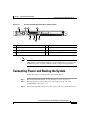
Connecting Power and Booting the System 3-13
Cisco Content Engine 511 and 566 Hardware Installation Guide
vi
OL-5756-01
Contents
Checking the LEDs 3-14
Removing or Replacing a Content Engine 3-14
CHAPTER
4
Installing Hardware Options 4-1
Removing the Cover and Bezel 4-1
Installing Adapters 4-3
Installing an MPEG Decoder Adapter 4-5
Preparing and Installing a Fibre Channel Adapter 4-8
Preparing to Install the Adapter 4-9
Installing the Fibre Channel Adapter 4-10
Troubleshooting the Fibre Channel Adapter Installation 4-10
Working with Hard Disk Drives 4-12
Installing a Hard Disk Drive in the CE-511 4-12
Installing a Hard Disk Drive in the CE-566 4-14
Assigning SCSI IDs 4-16
Completing the Installation 4-16
Installing the Content Engine Cover and Bezel 4-17
CHAPTER
5
Troubleshooting the System Hardware 5-1
Checking the Basics 5-1
Checking Connections and Switches 5-2
CHAPTER
6
Maintaining the Content Engine 6-1
Maintaining Your Site Environment 6-1
Temperature 6-2
Humidity 6-3
Altitude 6-3
Dust and Particles 6-3
Corrosion 6-4
Cisco Content Engine 511 and 566 Hardware Installation Guide
OL-5756-01
vii
Contents
Electrostatic Discharge 6-4
Electromagnetic and Radio Frequency Interference 6-5
Magnetism 6-5
Power Source Interruptions 6-6
Using Power Protection Devices 6-7
Surge Protectors 6-7
Line Conditioners 6-7
Uninterruptible Power Supplies 6-7
INDEX
Cisco Content Engine 511 and 566 Hardware Installation Guide
viii
OL-5756-01
Preface
This preface describes who should read the Cisco Content Engine 511 and 566
Hardware Installation Guide, how it is organized, and its document conventions.
This preface contains the following sections:
•
Document Objectives, page ix
•
Audience, page x
•
Document Organization, page x
•
Document Conventions, page xi
•
Obtaining Documentation, page xxi
•
Obtaining Documentation, page xxi
•
Documentation Feedback, page xxii
•
Obtaining Technical Assistance, page xxii
•
Obtaining Additional Publications and Information, page xxiv
Document Objectives
This installation guide explains how to prepare your site for installation, how to
install a Content Engine in an equipment rack, and how to maintain and
troubleshoot the system hardware. After completing the hardware installation
procedures covered in this guide, you will then use the appropriate companion
publications to configure your system. (See the “Obtaining Documentation”
section on page xxi.)
Cisco Content Engine 511 and 566 Hardware Installation Guide
OL-5756-01
ix
Preface
Audience
Audience
To use this hardware publication, you should be familiar with internetworking
equipment and cabling, and have a basic knowledge of electronic circuitry and
wiring practices.
To complete the installation, including the software configuration for the
Content Engine and for the router with which it works in conjunction, you should
be familiar with basic networking principles and router configuration, especially
web page protocols.
Warning
Only trained and qualified personnel should be allowed to install, replace, or
service this equipment. Statement 1030
Document Organization
This guide includes the following chapters:
Chapter
Title
Description
Chapter 1
Introducing the
Content Engine
Describes the physical properties and
provides a functional overview of the Cisco
Content Engine 511 and 566.
Chapter 2
Preparing to Install Describes safety considerations and gives an
the Content Engine overview of the installation and procedures
you should perform before the actual
installation.
Chapter 3
Installing the
Content Engine
Describes installing the hardware and
connecting the external network
interface cables.
Cisco Content Engine 511 and 566 Hardware Installation Guide
x
OL-5756-01
Preface
Document Conventions
Chapter
Title
Description
Chapter 4
Installing
Hardware Options
Describes how to remove and replace the
MPEG A/V decoder adapter, the
Fibre Channel adapter, and hard disk drives.
Chapter 5
Troubleshooting
the System
Hardware
Describes troubleshooting procedures for the
hardware installation.
Chapter 6
Maintaining the
Content Engine
Contains the procedures for keeping your
Content Engine in good condition.
Document Conventions
Command descriptions use the following conventions:
Convention
Description
boldface font
Commands and keywords are in boldface.
italic font
Variables for which you supply values are in italics.
[ ]
Elements in square brackets are optional.
{x | y | z}
Alternative keywords are grouped in braces and separated
by vertical bars.
[x | y | z]
Optional alternative keywords are grouped in brackets and
separated by vertical bars.
string
A nonquoted set of characters. Do not use quotation marks
around the string, or the string will include the
quotation marks.
Cisco Content Engine 511 and 566 Hardware Installation Guide
OL-5756-01
xi
Preface
Document Conventions
Screen examples use the following conventions:
Convention
screen
font
boldface screen
Description
Terminal sessions and information the system displays are
in screen font.
Information you must enter is in boldface screen font.
font
italic screen
font
Variables for which you supply values are in italic screen
font.
^
The symbol ^ represents the key labeled Control—for
example, the key combination ^D in a screen display means
hold down the Control key while you press the D key.
< >
Nonprinting characters, such as passwords, are in angle
brackets.
[ ]
Default responses to system prompts are in square brackets.
!, #
An exclamation point (!) or a pound sign (#) at the
beginning of a line of code indicates a comment line.
Notes, cautionary statements, and safety warnings use these conventions:
Note
Caution
Means reader take note. Notes contain helpful suggestions or references to
materials not contained in this manual.
Means reader be careful. You are capable of doing something that might result in
equipment damage or loss of data.
Cisco Content Engine 511 and 566 Hardware Installation Guide
xii
OL-5756-01
Preface
Document Conventions
Warning
IMPORTANT SAFETY INSTRUCTIONS
This warning symbol means danger. You are in a situation that could cause
bodily injury. Before you work on any equipment, be aware of the hazards
involved with electrical circuitry and be familiar with standard practices for
preventing accidents. Use the statement number provided at the end of each
warning to locate its translation in the translated safety warnings that
accompanied this device. Statement 1071
SAVE THESE INSTRUCTIONS
Waarschuwing
BELANGRIJKE VEILIGHEIDSINSTRUCTIES
Dit waarschuwingssymbool betekent gevaar. U verkeert in een situatie die
lichamelijk letsel kan veroorzaken. Voordat u aan enige apparatuur gaat
werken, dient u zich bewust te zijn van de bij elektrische schakelingen
betrokken risico's en dient u op de hoogte te zijn van de standaard praktijken
om ongelukken te voorkomen. Gebruik het nummer van de verklaring
onderaan de waarschuwing als u een vertaling van de waarschuwing die bij
het apparaat wordt geleverd, wilt raadplegen.
BEWAAR DEZE INSTRUCTIES
Varoitus
TÄRKEITÄ TURVALLISUUSOHJEITA
Tämä varoitusmerkki merkitsee vaaraa. Tilanne voi aiheuttaa ruumiillisia
vammoja. Ennen kuin käsittelet laitteistoa, huomioi sähköpiirien
käsittelemiseen liittyvät riskit ja tutustu onnettomuuksien yleisiin
ehkäisytapoihin. Turvallisuusvaroitusten käännökset löytyvät laitteen
mukana toimitettujen käännettyjen turvallisuusvaroitusten joukosta
varoitusten lopussa näkyvien lausuntonumeroiden avulla.
SÄILYTÄ NÄMÄ OHJEET
Cisco Content Engine 511 and 566 Hardware Installation Guide
OL-5756-01
xiii
Preface
Document Conventions
Attention
IMPORTANTES INFORMATIONS DE SÉCURITÉ
Ce symbole d'avertissement indique un danger. Vous vous trouvez dans une
situation pouvant entraîner des blessures ou des dommages corporels. Avant
de travailler sur un équipement, soyez conscient des dangers liés aux circuits
électriques et familiarisez-vous avec les procédures couramment utilisées
pour éviter les accidents. Pour prendre connaissance des traductions des
avertissements figurant dans les consignes de sécurité traduites qui
accompagnent cet appareil, référez-vous au numéro de l'instruction situé à la
fin de chaque avertissement.
CONSERVEZ CES INFORMATIONS
Warnung
WICHTIGE SICHERHEITSHINWEISE
Dieses Warnsymbol bedeutet Gefahr. Sie befinden sich in einer Situation, die
zu Verletzungen führen kann. Machen Sie sich vor der Arbeit mit Geräten mit
den Gefahren elektrischer Schaltungen und den üblichen Verfahren zur
Vorbeugung vor Unfällen vertraut. Suchen Sie mit der am Ende jeder Warnung
angegebenen Anweisungsnummer nach der jeweiligen Übersetzung in den
übersetzten Sicherheitshinweisen, die zusammen mit diesem Gerät
ausgeliefert wurden.
BEWAHREN SIE DIESE HINWEISE GUT AUF.
Avvertenza
IMPORTANTI ISTRUZIONI SULLA SICUREZZA
Questo simbolo di avvertenza indica un pericolo. La situazione potrebbe
causare infortuni alle persone. Prima di intervenire su qualsiasi
apparecchiatura, occorre essere al corrente dei pericoli relativi ai circuiti
elettrici e conoscere le procedure standard per la prevenzione di incidenti.
Utilizzare il numero di istruzione presente alla fine di ciascuna avvertenza per
individuare le traduzioni delle avvertenze riportate in questo documento.
CONSERVARE QUESTE ISTRUZIONI
Cisco Content Engine 511 and 566 Hardware Installation Guide
xiv
OL-5756-01
Preface
Document Conventions
Advarsel
VIKTIGE SIKKERHETSINSTRUKSJONER
Dette advarselssymbolet betyr fare. Du er i en situasjon som kan føre til skade
på person. Før du begynner å arbeide med noe av utstyret, må du være
oppmerksom på farene forbundet med elektriske kretser, og kjenne til
standardprosedyrer for å forhindre ulykker. Bruk nummeret i slutten av hver
advarsel for å finne oversettelsen i de oversatte sikkerhetsadvarslene som
fulgte med denne enheten.
TA VARE PÅ DISSE INSTRUKSJONENE
Aviso
INSTRUÇÕES IMPORTANTES DE SEGURANÇA
Este símbolo de aviso significa perigo. Você está em uma situação que poderá
ser causadora de lesões corporais. Antes de iniciar a utilização de qualquer
equipamento, tenha conhecimento dos perigos envolvidos no manuseio de
circuitos elétricos e familiarize-se com as práticas habituais de prevenção de
acidentes. Utilize o número da instrução fornecido ao final de cada aviso para
localizar sua tradução nos avisos de segurança traduzidos que acompanham
este dispositivo.
GUARDE ESTAS INSTRUÇÕES
¡Advertencia!
INSTRUCCIONES IMPORTANTES DE SEGURIDAD
Este símbolo de aviso indica peligro. Existe riesgo para su integridad física.
Antes de manipular cualquier equipo, considere los riesgos de la corriente
eléctrica y familiarícese con los procedimientos estándar de prevención de
accidentes. Al final de cada advertencia encontrará el número que le ayudará
a encontrar el texto traducido en el apartado de traducciones que acompaña
a este dispositivo.
GUARDE ESTAS INSTRUCCIONES
Cisco Content Engine 511 and 566 Hardware Installation Guide
OL-5756-01
xv
Preface
Document Conventions
Varning!
VIKTIGA SÄKERHETSANVISNINGAR
Denna varningssignal signalerar fara. Du befinner dig i en situation som kan
leda till personskada. Innan du utför arbete på någon utrustning måste du vara
medveten om farorna med elkretsar och känna till vanliga förfaranden för att
förebygga olyckor. Använd det nummer som finns i slutet av varje varning för
att hitta dess översättning i de översatta säkerhetsvarningar som medföljer
denna anordning.
SPARA DESSA ANVISNINGAR
Cisco Content Engine 511 and 566 Hardware Installation Guide
xvi
OL-5756-01
Preface
Document Conventions
Aviso
INSTRUÇÕES IMPORTANTES DE SEGURANÇA
Este símbolo de aviso significa perigo. Você se encontra em uma situação em
que há risco de lesões corporais. Antes de trabalhar com qualquer
equipamento, esteja ciente dos riscos que envolvem os circuitos elétricos e
familiarize-se com as práticas padrão de prevenção de acidentes. Use o
número da declaração fornecido ao final de cada aviso para localizar sua
tradução nos avisos de segurança traduzidos que acompanham o dispositivo.
GUARDE ESTAS INSTRUÇÕES
Cisco Content Engine 511 and 566 Hardware Installation Guide
OL-5756-01
xvii
Preface
Document Conventions
Advarsel
VIGTIGE SIKKERHEDSANVISNINGER
Dette advarselssymbol betyder fare. Du befinder dig i en situation med risiko
for legemesbeskadigelse. Før du begynder arbejde på udstyr, skal du være
opmærksom på de involverede risici, der er ved elektriske kredsløb, og du
skal sætte dig ind i standardprocedurer til undgåelse af ulykker. Brug
erklæringsnummeret efter hver advarsel for at finde oversættelsen i de
oversatte advarsler, der fulgte med denne enhed.
GEM DISSE ANVISNINGER
Cisco Content Engine 511 and 566 Hardware Installation Guide
xviii
OL-5756-01
Preface
Document Conventions
Cisco Content Engine 511 and 566 Hardware Installation Guide
OL-5756-01
xix
Preface
Document Conventions
Cisco Content Engine 511 and 566 Hardware Installation Guide
xx
OL-5756-01
Preface
Obtaining Documentation
Obtaining Documentation
Cisco documentation and additional literature are available on Cisco.com. Cisco
also provides several ways to obtain technical assistance and other technical
resources. These sections explain how to obtain technical information from Cisco
Systems.
Cisco.com
You can access the most current Cisco documentation at this URL:
http://www.cisco.com/univercd/home/home.htm
You can access the Cisco website at this URL:
http://www.cisco.com
You can access international Cisco websites at this URL:
http://www.cisco.com/public/countries_languages.shtml
Ordering Documentation
You can find instructions for ordering documentation at this URL:
http://www.cisco.com/univercd/cc/td/doc/es_inpck/pdi.htm
You can order Cisco documentation in these ways:
•
Registered Cisco.com users (Cisco direct customers) can order Cisco product
documentation from the Ordering tool:
http://www.cisco.com/en/US/partner/ordering/index.shtml
•
Nonregistered Cisco.com users can order documentation through a local
account representative by calling Cisco Systems Corporate Headquarters
(California, USA) at 408 526-7208 or, elsewhere in North America, by
calling 1 800 553-NETS (6387).
Cisco Content Engine 511 and 566 Hardware Installation Guide
OL-5756-01
xxi
Preface
Documentation Feedback
Documentation Feedback
You can send comments about technical documentation to [email protected].
You can submit comments by using the response card (if present) behind the front
cover of your document or by writing to the following address:
Cisco Systems
Attn: Customer Document Ordering
170 West Tasman Drive
San Jose, CA 95134-9883
We appreciate your comments.
Obtaining Technical Assistance
For all customers, partners, resellers, and distributors who hold valid Cisco
service contracts, Cisco Technical Support provides 24-hour-a-day,
award-winning technical assistance. The Cisco Technical Support Website on
Cisco.com features extensive online support resources. In addition, Cisco
Technical Assistance Center (TAC) engineers provide telephone support. If you
do not hold a valid Cisco service contract, contact your reseller.
Cisco Technical Support Website
The Cisco Technical Support Website provides online documents and tools for
troubleshooting and resolving technical issues with Cisco products and
technologies. The website is available 24 hours a day, 365 days a year, at this
URL:
http://www.cisco.com/techsupport
Access to all tools on the Cisco Technical Support Website requires a Cisco.com
user ID and password. If you have a valid service contract but do not have a user
ID or password, you can register at this URL:
http://tools.cisco.com/RPF/register/register.do
Cisco Content Engine 511 and 566 Hardware Installation Guide
xxii
OL-5756-01
Preface
Obtaining Technical Assistance
Note
Use the Cisco Product Identification (CPI) tool to locate your product serial
number before submitting a web or phone request for service. You can access the
CPI tool from the Cisco Technical Support Website by clicking the Tools &
Resources link under Documentation & Tools. Choose Cisco Product
Identification Tool from the Alphabetical Index drop-down list, or click the
Cisco Product Identification Tool link under Alerts & RMAs. The CPI tool
offers three search options: by product ID or model name; by tree view; or for
certain products, by copying and pasting show command output. Search results
show an illustration of your product with the serial number label location
highlighted. Locate the serial number label on your product and record the
information before placing a service call.
Submitting a Service Request
Using the online TAC Service Request Tool is the fastest way to open S3 and S4
service requests. (S3 and S4 service requests are those in which your network is
minimally impaired or for which you require product information.) After you
describe your situation, the TAC Service Request Tool provides recommended
solutions. If your issue is not resolved using the recommended resources, your
service request is assigned to a Cisco TAC engineer. The TAC Service Request
Tool is located at this URL:
http://www.cisco.com/techsupport/servicerequest
For S1 or S2 service requests or if you do not have Internet access, contact the
Cisco TAC by telephone. (S1 or S2 service requests are those in which your
production network is down or severely degraded.) Cisco TAC engineers are
assigned immediately to S1 and S2 service requests to help keep your business
operations running smoothly.
To open a service request by telephone, use one of the following numbers:
Asia-Pacific: +61 2 8446 7411 (Australia: 1 800 805 227)
EMEA: +32 2 704 55 55
USA: 1 800 553-2447
For a complete list of Cisco TAC contacts, go to this URL:
http://www.cisco.com/techsupport/contacts
Cisco Content Engine 511 and 566 Hardware Installation Guide
OL-5756-01
xxiii
Preface
Obtaining Additional Publications and Information
Definitions of Service Request Severity
To ensure that all service requests are reported in a standard format, Cisco has
established severity definitions.
Severity 1 (S1)—Your network is “down,” or there is a critical impact to your
business operations. You and Cisco will commit all necessary resources around
the clock to resolve the situation.
Severity 2 (S2)—Operation of an existing network is severely degraded, or
significant aspects of your business operation are negatively affected by
inadequate performance of Cisco products. You and Cisco will commit full-time
resources during normal business hours to resolve the situation.
Severity 3 (S3)—Operational performance of your network is impaired, but most
business operations remain functional. You and Cisco will commit resources
during normal business hours to restore service to satisfactory levels.
Severity 4 (S4)—You require information or assistance with Cisco product
capabilities, installation, or configuration. There is little or no effect on your
business operations.
Obtaining Additional Publications and Information
Information about Cisco products, technologies, and network solutions is
available from various online and printed sources.
•
Cisco Marketplace provides a variety of Cisco books, reference guides, and
logo merchandise. Visit Cisco Marketplace, the company store, at this URL:
http://www.cisco.com/go/marketplace/
•
The Cisco Product Catalog describes the networking products offered by
Cisco Systems, as well as ordering and customer support services. Access the
Cisco Product Catalog at this URL:
http://cisco.com/univercd/cc/td/doc/pcat/
•
Cisco Press publishes a wide range of general networking, training and
certification titles. Both new and experienced users will benefit from these
publications. For current Cisco Press titles and other information, go to Cisco
Press at this URL:
http://www.ciscopress.com
Cisco Content Engine 511 and 566 Hardware Installation Guide
xxiv
OL-5756-01
Preface
Obtaining Additional Publications and Information
•
Packet magazine is the Cisco Systems technical user magazine for
maximizing Internet and networking investments. Each quarter, Packet
delivers coverage of the latest industry trends, technology breakthroughs, and
Cisco products and solutions, as well as network deployment and
troubleshooting tips, configuration examples, customer case studies,
certification and training information, and links to scores of in-depth online
resources. You can access Packet magazine at this URL:
http://www.cisco.com/packet
•
iQ Magazine is the quarterly publication from Cisco Systems designed to
help growing companies learn how they can use technology to increase
revenue, streamline their business, and expand services. The publication
identifies the challenges facing these companies and the technologies to help
solve them, using real-world case studies and business strategies to help
readers make sound technology investment decisions. You can access iQ
Magazine at this URL:
http://www.cisco.com/go/iqmagazine
•
Internet Protocol Journal is a quarterly journal published by Cisco Systems
for engineering professionals involved in designing, developing, and
operating public and private internets and intranets. You can access the
Internet Protocol Journal at this URL:
http://www.cisco.com/ipj
•
World-class networking training is available from Cisco. You can view
current offerings at this URL:
http://www.cisco.com/en/US/learning/index.html
Cisco Content Engine 511 and 566 Hardware Installation Guide
OL-5756-01
xxv
Preface
Obtaining Additional Publications and Information
Cisco Content Engine 511 and 566 Hardware Installation Guide
xxvi
OL-5756-01
C H A P T E R
1
Introducing the Content Engine
This chapter provides a basic functional overview of the Cisco Content Engine
511 and 566 (CE-511 and CE-566), and describes the Content Engine hardware,
major components, and front and back panel indicators and controls.
This chapter contains the following sections:
•
Introduction, page 1-1
•
Functional Description, page 1-4
•
Hardware Features, page 1-6
•
Specifications, page 1-17
•
Regulatory Compliance, page 1-20
•
Class A Warning Statements, page 1-22
Introduction
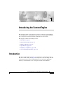
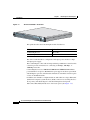
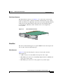
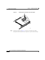
The CE-511 and CE-566 (see Figure 1-1) are Internet content delivery devices
that offer content caching, hosting, content replication, video streaming, and other
content-based services. The Content Engine is positioned on the WAN edge
between your small business site or enterprise network and the Internet.
Cisco Content Engine 511 and 566 Hardware Installation Guide
OL-5756-01
1-1
Chapter 1
Introducing the Content Engine
Introduction
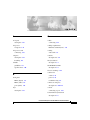
CE-511 and CE-566—Front View
115770
Figure 1-1
This guide describes the Content Engine models listed below.
Model
Product Number
Content Engine 511
CE-511-K9
Content Engine 566
CE-566A-144GB-K9
The CE-511 and CE-566 are configured for AC-input power and have a single
AC-input power supply.
The Content Engine comes with an integrated dual-port Ethernet controller. This
controller provides an interface for connecting to 10-Mbps, 100-Mbps, or
1000-Mbps networks.
Content Engines have two 10BASE-T/100BASE-TX/1000BASE-TX Ethernet
ports with RJ-45 receptacles. Both Ethernet ports support autodetect speed mode
and full-duplex operation, which enable simultaneous transmission and reception
of data on the Ethernet LAN.
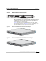
In addition, the CE-566 is configured with one Ultra320 low-voltage differential
(LVD) small computer system interface (SCSI) connector for attaching the Cisco
Storage Array. The SCSI adapter is installed in Peripheral Component
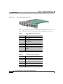
Interconnect-Extended (PCI-X) slot 2 on the back panel. (See Figure 1-2.)
Cisco Content Engine 511 and 566 Hardware Installation Guide
1-2
OL-5756-01
Chapter 1
Introducing the Content Engine
Introduction
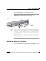
Figure 1-2
CE-566 Back Panel with SCSI Port Connector
124684
SCSI port connector
CE-511 and 566 Models can be configured with either a Fibre Channel adapter or
an MPEG A/V decoder adapter. These adapters are user-replaceable and are
installed in PCI-X slot 1 on the back panel.
Figure 1-3 shows the CE-511 and CE-566 back panel with a Fibre Channel
adapter installed in slot PCI 1, and Figure 1-4 shows the Content Engine back
panel with an MPEG A/V decoder adapter installed in slot PCI 1.
CE-511 and CE-566 Back Panel with Fibre Channel Adapter
Figure 1-4
CE-511 and CE-566 Back Panel with MPEG A/V Decoder Adapter
115771
124656
Figure 1-3
Cisco Content Engine 511 and 566 Hardware Installation Guide
OL-5756-01
1-3
Chapter 1
Introducing the Content Engine
Functional Description
Content Engine 511
The Content Engine 511 (CE-511) is a base-end Content Engine that services
small- to medium-size enterprise networks.
Table 1-1 lists memory specifications for the CE-511.
Table 1-1
CE-511 Memory Specifications
Specification
Description
Memory
512 MB DRAM
Hard disk drives
1 80-GB SATA1 hard disk drive (CE-511-DISK-80GB)
Note
The Content Engine 511 can be upgraded to a
maximum of 2 hard disk drives.
1. SATA = Serial Advanced Technology Attachment
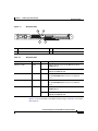
Content Engine 566
The Content Engine 566 (CE-566) is a mid-range Content Engine that services
medium- to large-size enterprise networks.
Table 1-2 lists memory specifications for the CE-566.
Table 1-2
CE-566 Memory Specifications
Specification
Description
Memory
1 GB DRAM
Hard disk drives
2 72-GB SCSI hard disk drives (CE-566-DISK-72GB)
Functional Description
The Content Engine operates either as a component of a Cisco Application and
Content Networking System (ACNS) or as a standalone content-caching device
and is generally positioned on the WAN edge between your enterprise and
the Internet.
Cisco Content Engine 511 and 566 Hardware Installation Guide
1-4
OL-5756-01
Chapter 1
Introducing the Content Engine
Functional Description
The CE-566 supports device mode configuration and can be configured through
ACNS 5.x software to operate as a Content Engine, a Content Router, a Content
Distribution Manager, or an IP/TV Program Manager. The CE-511, however, does
not support device mode configuration.
Content Delivery Network Component
Cisco Content Engines with Cisco ACNS software installed are the content
delivery components of a larger Cisco ACNS network solution, which includes
content routing and content distribution and management. Content Engines with
Cisco ACNS 5.x software are deployed in conjunction with a Content Distribution
Manager to create a centrally managed ACNS network.
The ACNS solution offers accelerated content delivery, hosting, content
replication, video streaming, and other content-based services. The ACNS
solution addresses the need to distribute and receive high-bandwidth, media-rich
content across the Internet or an intranet without performance losses or content
delivery delays.
Content Caching Device
Cisco Content Engines with Cisco ACNS software installed accelerate content
delivery and optimize bandwidth usage by transparently caching frequently
accessed content and fulfilling content requests locally rather than traversing the
Internet or intranet to a distant server farm each time a request is made. The
Content Engine works in tandem with a router to handle web traffic, including
user requests to view pages and graphics (objects) on World Wide Web
servers—whether internal or external to your network.
To deploy Cisco Content Engines with Cisco ACNS software within your existing
network, your network must support Cisco IOS software and the Web Cache
Communication Protocol (WCCP). WCCP transparently redirects HTTP requests
to a Content Engine, and the Content Engine responds to those requests.
For example, when a user requests an object from a web server, the router first
sends the request to a Content Engine. If the Content Engine has a copy of the
requested object in storage, the Content Engine sends the user the object.
Cisco Content Engine 511 and 566 Hardware Installation Guide
OL-5756-01
1-5
Chapter 1
Introducing the Content Engine
Hardware Features
Otherwise, the Content Engine simultaneously obtains the requested objects from
the web server, stores a copy of the objects (caches them), and forwards the
objects on to the user.
You can also configure your Content Engine as a proxy server that acts as a
network gateway device, which is optimized to retrieve content on behalf of web
clients. Direct proxy routing is known as nontransparent caching because the web
clients and media players in the network are configured to explicitly point to the
Content Engine that is acting as the proxy server.
Note
Unlike transparent caching, nontransparent caching is possible even if your
network does not support Cisco IOS software and the WCCP.
In nontransparent caching cases, the Content Engine sends the content to the web
client from its local storage if the requested content is already available at that
location (cache hit). If the requested content is not already stored in the Content
Engine’s local cache (cache miss), the Content Engine retrieves the requested
content from the origin server, stores a local copy of the content if the content is
cacheable, and sends the requested content to the web client. When the Content
Engine receives subsequent requests for the same content, it sends the content
from its local storage.
By caching web objects, the Content Engine can speed the completion of user
requests when more than one user wants to access the same objects. Caching in
this manner also reduces the amount of traffic between your network and the
Internet, potentially improving your overall network performance and optimizing
your bandwidth usage.
Hardware Features
This section illustrates and describes the front and back panel controls, ports, and
LED indicators on the CE-511 and CE-566.
Cisco Content Engine 511 and 566 Hardware Installation Guide
1-6
OL-5756-01
Chapter 1
Introducing the Content Engine
Hardware Features
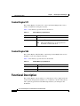
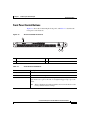
Front Panel Control Buttons
Figure 1-5 shows the Content Engine front panel, and Table 1-3 describes the
front panel control buttons.
Figure 1-5
CE-511 and CE-566 Front Panel
124658
1
3
1
CD eject button
3
Reset button
Table 1-3
2
2
Power control button
Front Panel Control Buttons
Item
Description
CD eject button
Releases a CD from the drive.
Power control button
Turns on the Content Engine.
Reset button
Resets the Content Engine and runs the power-on self-test (POST). You
might need to use a pen or the end of a straightened paper clip to press the
button.
Note
This is a hardware reset button and does not restore the device to the
factory default software settings.
Cisco Content Engine 511 and 566 Hardware Installation Guide
OL-5756-01
1-7
Chapter 1
Introducing the Content Engine
Hardware Features
LED Indicators
Figure 1-6 shows the location of front panel LEDs, and Table 1-4 describes
their function.
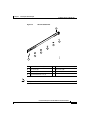
Figure 1-6
Front Panel LEDs
3
2
4
5
115772
1
1
CD-ROM drive activity
2
System error
3
System locator (not supported on
Content Engine models)
4
Hard disk drive activity
5
Power
Table 1-4
Front Panel LEDs
LED
Color
State
Description
CD-ROM drive
activity
Green
On
Indicates that the CD-ROM drive is in use.
System error
Amber
On
Indicates that a system error has occurred.
Hard disk drive
activity
Green
Flashing
Indicates that the associated hard disk drive is in use.
Power
Green
On
Indicates that power is flowing to the Content Engine.
Flashing
Indicates that the Content Engine is in standby mode.
Figure 1-7 shows the location of back panel LEDs, and Table 1-5 describes
their function.
Cisco Content Engine 511 and 566 Hardware Installation Guide
1-8
OL-5756-01
Chapter 1
Introducing the Content Engine
Hardware Features
Figure 1-7
Back Panel LEDs
2
115803
1
4
3
1
Ethernet 1 link
2
Ethernet 1 activity
3
Ethernet 2 activity
4
Ethernet 2 link
Table 1-5
Back Panel LEDs
Indicator
Color
State
Description
Ethernet 1 link
Green
On
Indicates that the speed of the Ethernet LAN is
1000BASE-TX.
Off
Indicates that the speed of the Ethernet LAN is
10BASE-T/100BASE-TX.
Ethernet 1 activity
Green
Blinking
Indicates that there is an active link connection on
the 10/100/1000BASE-T interface for Ethernet
port 1.
Ethernet 2 activity
Green
Blinking
Indicates that there is an active link connection on
the 10/100/1000BASE-T interface for Ethernet
port 2.
Ethernet 2 link
Green
On
Indicates that the speed of the Ethernet LAN is
1000BASE-TX.
Off
Indicates that the speed of the Ethernet LAN is
10BASE-T/100BASE-TX.
Figure 1-8 shows the LEDs for the Fibre Channel adapter, and Table 1-6 describes
their function.
Cisco Content Engine 511 and 566 Hardware Installation Guide
OL-5756-01
1-9
Chapter 1
Introducing the Content Engine
Hardware Features
Fibre Channel Adapter LEDs
83287
Figure 1-8
Note
Table 1-6
In the illustration, the top LED is green, and the bottom LED is amber.
Fibre Channel Adapter LEDs
LED
State
Meaning
Green
On
Power is on.
Amber
On
Green
On
Amber
Off
Green
Off
Amber
On
Signal has been acquired. (The Fibre Channel
adapter firmware is performing or waiting to
perform Fibre Channel loop initialization.)
Green
Off
Loss of synchronization.
Amber
Flashing
Green
Flashing
Amber
Flashing
Note
Fibre Channel adapter is online.
Firmware error.
The MPEG A/V decoder adapter does not have any LEDs.
Cisco Content Engine 511 and 566 Hardware Installation Guide
1-10
OL-5756-01
Chapter 1
Introducing the Content Engine
Hardware Features
Input/Output Ports and Connectors
Your Content Engine supports the following I/O connectors on the back of the
device:
•
Ethernet connectors
•
Serial connector
•
SCSI low-voltage differential (LVD) connector (CE-566 only)
•
Fibre Channel connector (on optional adapter)
•
Video and audio connectors (on optional adapter)
To avoid electric shock, do not connect safety extra-low voltage (SELV) circuits
to telephone-network voltage (TNV) circuits. LAN ports contain SELV circuits,
and WAN ports contain TNV circuits. Some LAN and WAN ports both use RJ-45
connectors. Use caution when connecting cables. Statement 1021
Warning
Figure 1-9 shows the location of the Content Engine back panel ports
and receptacles.
Figure 1-9
CE-511 and CE-566 Back Panel Ports and Receptacles
2
3
4
115773
1
8
7
5
6
1
AC power receptacle
2
Mouse port
3
Keyboard port
4
Ethernet 1 receptacle
5
Ethernet 2 receptacle
6
USB ports (not supported)
7
Monitor port
8
Serial port
Cisco Content Engine 511 and 566 Hardware Installation Guide
OL-5756-01
1-11
Chapter 1
Introducing the Content Engine
Hardware Features
Note
Cisco ACNS software does not support the use of a keyboard or mouse (Personal
System 2 [PS/2] or Universal Serial Bus [USB]) with the Content Engine.
However, keyboard and mouse are supported by the BIOS for power-on self-test
(POST), and the configuration/setup utility.
Table 1-7 describes the back panel ports and receptacles.
Table 1-7
Back Panel Ports and Connectors
Item
Description
AC power receptacle
The AC power cord connects to this plug.
Ethernet 1 port
This 10/100/1000BASE-T port is autosensing with
full-duplex capability; it connects your
Content Engine to the Ethernet LAN.
Ethernet 2 port
This 10/100/1000BASE-T port is autosensing with
full-duplex capability; it connects your
Content Engine to the Ethernet LAN.
Serial port
This is a standard serial port for connecting to a
console or terminal.
SCSI LVD port (CE-566
only) (See Figure 1-2)
Use this port to attach an external Cisco
Storage Array device.
Fibre Channel port (on
optional adapter)
This port provides the option to connect to an
external Fibre Array device or SAN1 for added data
storage capacity.
Audio/video port (on
optional MPEG A/V
decoder adapter)
•
3 BNC2 connectors for YUV, RGB3, and
composite video output
•
Mini-XLR 8-pin connector for S/PDIF4 and
analog stereo audio output
•
Mini-XLR 8-pin connector for VGA5 output
1. SAN = storage area network
2. BNC = Bayonet Neill-Concelman
3. RGB = red green blue
4. S/PDIF = Sony/Philips Digital Interface
5. VGA = video graphics array
Cisco Content Engine 511 and 566 Hardware Installation Guide
1-12
OL-5756-01
Chapter 1
Introducing the Content Engine
Hardware Features
Ethernet Port
The Content Engine comes with one integrated dual-port Ethernet controller. This
controller provides an interface for connecting to 10-Mbps, 100-Mbps, or
1000-Mbps networks and provides full-duplex (FDX) capability, which enables
simultaneous transmission and reception of data on the Ethernet LAN.
To access the Ethernet port, connect a Category 3, 4, or 5 unshielded twisted-pair
(UTP) cable to the RJ-45 connector on the back of the device.
Note
The 100BASE-TX/1000BASE-TX Ethernet standard requires that the cabling in
the network be Category 5 or higher.
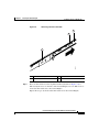
Ethernet Port Connector
Figure 1-10 shows the pin number assignments for the Ethernet RJ-45 port.
Figure 1-10
Ethernet Port Connector
Link LED
(green)
83195
Activity LED
(green)
8
1
Serial Port
The Content Engine has one standard serial port connector located on the back of
the device.
Serial Port Connector
Figure 1-11 shows the pin number assignments for the 9-pin, male D-shell serial
port connector on the back of the device. These pin number assignments conform
to the industry standard.
Cisco Content Engine 511 and 566 Hardware Installation Guide
OL-5756-01
1-13
Chapter 1
Introducing the Content Engine
Hardware Features
Figure 1-11
Serial Port Connector
5
83193
1
6
9
SCSI Port
The CE-566 has one SCSI LVD port connector located on the back of the device.
A cable for this port is provided when you purchase a Cisco Storage Array.
When you attach an external SCSI device to the SCSI connector, you must set a
unique ID for the device. Refer to the information that comes with the device for
instructions on how to set its SCSI ID.
SCSI Connector
Figure 1-12 shows a 68-pin, female D-shell SCSI connector. These connectors
conform to the SCSI standard.
Figure 1-12
SCSI Port Connector
1
68
35
83192
34
Fibre Channel Port
The CE-511 and CE-566 support one optional Fibre Channel adapter that has a
single Fibre Channel port.
Cisco Content Engine 511 and 566 Hardware Installation Guide
1-14
OL-5756-01
Chapter 1
Introducing the Content Engine
Hardware Features
Fibre Channel Connector
The Fibre Channel connector (see Figure 1-13) is an LC-style connector that
supports nonoptical fibre conductive (nonOFC), multimode fiber-optic cabling
using a small form factor (SFF) fiber-optic transceiver module. The Fibre Channel
adapter uses LC-LC Fibre Channel cables. The total cable length should not
exceed 1640 feet (500 meters). Fibre Channel cables are not supplied by
Cisco Systems.
Fibre Channel Connector
83287
Figure 1-13
Video Port
The CE-511 and CE-566 support one optional MPEG A/V decoder adapter that
has one audio and video input/output port.
Video Connectors
Figure 1-14 shows the following five connectors for the audio and video
input/output port:
•
3 BNC connectors for YUV, RGB, and composite video output
•
Mini-XLR 8-pin connector for Sony/Philips Digital Interface (S/PDIF) and
analog stereo audio output
•
Mini-XLR 8-pin connector for video graphics array (VGA) output
Cisco Content Engine 511 and 566 Hardware Installation Guide
OL-5756-01
1-15
Chapter 1
Introducing the Content Engine
Hardware Features
Video Input/Output Connectors
83288
Figure 1-14
Table 1-8 provides the pinout for the audio output mini-XLR 8-pin connector, and
Table 1-9 provides the pinout for the VGA output mini-XLR 8-pin connector.
Table 1-8
Audio Output Connector Pinout
Pin Number. Destination
1
Audio left (–)
2
Ground
3
Audio left (+)
4
Audio right (+)
5
Ground
6
Audio left (–)
7
Ground
8
S/PDIF
Table 1-9
VGA Output Connector Pinout
Pin Number
Destination
1
Vsync
2
Ground
3
Hsync
4
Blue
5
Ground
Cisco Content Engine 511 and 566 Hardware Installation Guide
1-16
OL-5756-01
Chapter 1
Introducing the Content Engine
Specifications
Table 1-9
VGA Output Connector Pinout (continued)
Pin Number
Destination
6
Red
7
Green
8
Ground
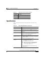
Specifications
Table 1-10 summarizes the features and specifications for the CE-511 and
CE-566.
Table 1-10
CE-511 and CE-566 Hardware Specifications
Specification
Description
Microprocessor
1 Intel 2.8-GHz Celeron 256-KB with Level 2 cache
and multimedia extensions (MMX2) technology
Expansion bays
Two 3.5-in. (8.89-cm) slim-height bays for hard
disk drives
Expansion slots
Two 66-/100-/133-MHz 64-bit PCI-X slots on the
system board (half-length full-height slots; one
low-profile and one full profile)
Hard disk controller
Adapters
•
CE-511—Serial advanced technology attachment
(ATA) controller
•
CE-566—Ultra320 SCSI controller
•
1-port Fibre Channel adapter
•
1-port MPEG A/V decoder adapter
Note
•
The CE-511 and CE-566 support either the
Fibre Channel adapter or the MPEG A/V
decoder adapter in PCI slot 1.
Ultra320 SCSI adapter installed in PCI slot 2
(CE-566 only)
Cisco Content Engine 511 and 566 Hardware Installation Guide
OL-5756-01
1-17
Chapter 1
Introducing the Content Engine
Specifications
Table 1-10
CE-511 and CE-566 Hardware Specifications (continued)
Specification
Fibre Channel adapter
MPEG A/V decoder
adapter
Description
•
Bus type: Fiber-optic media (shortwave
50-micron)
•
Bus transfer rate: 2 gigabits per second (Gbps)
maximum at half duplex and 4 Gbps at full
duplex
•
Protocols: Supports FCP1-SCSI protocol
Video specifications
•
S/N:2 10 kHz to 4.2 MHz; Y: 65 dB rms 3;
Pb: 70 dB rms; Pr: 70 dB rms
•
Frequency response: 0 to 4.0 MHz ± 2 dB
•
Sync tip: 40 IRE4 ± 4
•
Luma nonlinearity: 5%
•
Audio specifications
•
S/PDIF5
– PCM6 or compressed audio coding 3 (AC-3)
bitstream out
– 75-ohm, 0.5-V p-p7 ± 20%
– Rise and fall time: > 0.4 microseconds
measured from 10 to 90%
•
Analog
– Jumper-selectable balanced or unbalanced
audio (balanced = +4 dBm)
– Frequency response: 20 Hz to 22 kHz ±
0.5 dB
– Reference level: 0.5-V p-p ± 10%
– THD8+n:@20 Hz to 22 kHz < 0.5%
Power supply
1 AC-input
Cisco Content Engine 511 and 566 Hardware Installation Guide
1-18
OL-5756-01
Chapter 1
Introducing the Content Engine
Specifications
Table 1-10
Specification
Dimensions
Weight
Electrical input
CE-511 and CE-566 Hardware Specifications (continued)
Description
•
Height: 1.75 in., 1 RU (44 mm)
•
Depth: 20 in. (508 mm)
•
Width: 16.69 in. (430 mm)
Maximum weight: 28 lb (12.7 kg ) depending on
your configuration
•
Sine-wave input (47–63 Hz) required
•
Input voltage low range:
– Minimum: 100 VAC
– Maximum: 127 VAC
•
Input voltage high range:
– Minimum: 200 VAC
– Maximum: 240 VAC
•
Input kilovolt-amperes (kVA), approximately:
– Minimum: 0.20 kVA
– Maximum: 0.45 kVA
Ports
•
1000BASE-TX, 100BASE-TX, 10BASE-T
(dual) Ethernet ports
•
Serial port
•
2 USB ports
•
Ultra320 SCSI port (CE-566 only)
•
Fibre Channel port (on optional adapter)
•
Audio/video ports (on optional adapter):
– 3 BNC connectors
– 2 mini-XLR connectors
Cisco Content Engine 511 and 566 Hardware Installation Guide
OL-5756-01
1-19
Chapter 1
Introducing the Content Engine
Regulatory Compliance
Table 1-10
CE-511 and CE-566 Hardware Specifications (continued)
Specification
Temperature
Heat Dissipation
Humidity
Altitude
Acoustical noise
emissions
Description
•
Operating: 50 to 95° F (10 to 35° C)
•
Nonoperating: –40 to 140° F (–40 to +60° C)
•
Minimum configuration: 307 Btu9/hr (90 Watts
•
Maximum configuration: 850 Btu/hr (250 Watts)
•
Operating: 8 to 80%
•
Nonoperating: 8 to 80%
Maximum altitude: 6998 ft (2133 m)
•
Sound power, idling: 6.5 bel maximum
•
Sound power, operating: 6.5 bel maximum
1. FCP = Fibre Channel Protocol
2. S/N = signal-to-noise ratio
3. rms = root mean square
4. IRE = Institute of Radio Engineers
5. S/PDIF = Sony/Philips Digital Interface
6. PCM = pulse-coded modulation
7. p-p = peak to peak
8. THD = total harmonic distortion
9. Btu = British thermal unit
Regulatory Compliance
Table 1-11 lists regulatory compliance and agency approvals for the CE-511
and CE-566.
Cisco Content Engine 511 and 566 Hardware Installation Guide
1-20
OL-5756-01
Chapter 1
Introducing the Content Engine
Regulatory Compliance
Table 1-11
Regulatory Compliance
Item
Description
Compliance
CE Marking
Safety
UL 1950
CSA-C22.2 No. 950
EN 60950
IEC 60950
EMC
FCC Part 15 (CFR 47) Class A
ICES-003 Class A
EN 55022 Class A with UTP cables
CISPR22 Class A with UTP cables
AS/NZS 3548 Class A with UTP cables
VCCI Class A with UTP cables
EN 55024
EN 50082-1
Cisco Content Engine 511 and 566 Hardware Installation Guide
OL-5756-01
1-21
Chapter 1
Introducing the Content Engine
Class A Warning Statements
Class A Warning Statements
VCCI Class A Warning for Japan
Warning
This is a Class A product based on the standard of the Voluntary Control
Council for Interference by Information Technology Equipment (VCCI). If this
equipment is used in a domestic environment, radio disturbance may arise.
When such trouble occurs, the user may be required to take corrective
actions. Statement 191
Class A Notice for Taiwan and Other Traditional Chinese
Markets
Warning
This is a Class A Information Product, when used in residential environment,
it may cause radio frequency interference, under such circumstances, the
user may be requested to take appropriate countermeasures. Statement 257
Cisco Content Engine 511 and 566 Hardware Installation Guide
1-22
OL-5756-01
Chapter 1
Introducing the Content Engine
Class A Warning Statements
Class A Warning for Hungary
Warning
This equipment is a class A product and should be used and installed properly
according to the Hungarian EMC Class A requirements (MSZEN55022). Class A
equipment is designed for typical commercial establishments for which
special conditions of installation and protection distance are used.
Statement 256
Cisco Content Engine 511 and 566 Hardware Installation Guide
OL-5756-01
1-23
Chapter 1
Introducing the Content Engine
Class A Warning Statements
Cisco Content Engine 511 and 566 Hardware Installation Guide
1-24
OL-5756-01
C H A P T E R
2
Preparing to Install the Content Engine
This chapter contains important safety information you should know before
working with the Content Engine. Use the following guidelines to ensure your
own personal safety and to help protect your Content Engine from potential
damage.
This chapter contains the following sections:
Note
•
Safety Warnings, page 2-1
•
Safety Guidelines, page 2-4
Read the Regulatory Compliance and Safety Information for the Cisco Content
Networking Product Series document that came with your Content Engine before
you begin the installation.
Safety Warnings
Before you install the Content Engine, observe the following safety warnings.
Warning
Only trained and qualified personnel should be allowed to install, replace, or
service this equipment. Statement 1030
Cisco Content Engine 511 and 566 Hardware Installation Guide
OL-5756-01
2-1
Chapter 2
Preparing to Install the Content Engine
Safety Warnings
Warning
Read the installation instructions before connecting the system to the power
source. Statement 1004
Warning
Before working on a system that has an on/off switch, turn OFF the power and
unplug the power cord. Statement 1
Warning
This unit might have more than one power supply connection. All connections
must be removed to de-energize the unit. Statement 1028
Warning
This unit is intended for installation in restricted access areas. A restricted
access area is where access can only be gained by service personnel through
the use of a special tool, lock and key, or other means of security, and is
controlled by the authority responsible for the location. Statement 37
Warning
To avoid electric shock, do not connect safety extra-low voltage (SELV) circuits
to telephone-network voltage (TNV) circuits. LAN ports contain SELV circuits,
and WAN ports contain TNV circuits. Some LAN and WAN ports both use RJ-45
connectors. Use caution when connecting cables. Statement 1021
Warning
This product relies on the building’s installation for short-circuit (overcurrent)
protection. Ensure that a fuse or circuit breaker no larger than 120 VAC, 15A U.S.
(240 VAC, 10A international) is used on the phase conductors (all
current-carrying conductors). Statement 13
Warning
This equipment must be grounded. Never defeat the ground conductor or
operate the equipment in the absence of a suitably installed ground conductor.
Contact the appropriate electrical inspection authority or an electrician if you
are uncertain that suitable grounding is available. Statement 1024
Cisco Content Engine 511 and 566 Hardware Installation Guide
2-2
OL-5756-01
Chapter 2
Preparing to Install the Content Engine
Safety Warnings
Warning
Do not work on the system or connect or disconnect cables during periods of
lightning activity. Statement 1001
Warning
Before working on equipment that is connected to power lines, remove jewelry
(including rings, necklaces, and watches). Metal objects will heat up when
connected to power and ground and can cause serious burns or weld the metal
object to the terminals. Statement 43
Warning
When installing or replacing the unit, the ground connection must always be
made first and disconnected last. Statement 1046
Warning
The safety cover is an integral part of the product. Do not operate the unit
without the safety cover installed. Operating the unit without the cover in place
will invalidate the safety approvals and pose a risk of fire and electrical
hazards. Statement 117
Warning
Blank faceplates and cover panels serve three important functions: they
prevent exposure to hazardous voltages and currents inside the chassis; they
contain electromagnetic interference (EMI) that might disrupt other equipment;
and they direct the flow of cooling air through the chassis. Do not operate the
system unless all cards, faceplates, front covers, and rear covers are in place.
Statement 1029
Warning
There is the danger of explosion if the battery is replaced incorrectly. Replace
the battery only with the same or equivalent type recommended by the
manufacturer. Dispose of used batteries according to the manufacturer’s
instructions. Statement 1015
Warning
Ultimate disposal of this product should be handled according to all national
laws and regulations. Statement 1040
Cisco Content Engine 511 and 566 Hardware Installation Guide
OL-5756-01
2-3
Chapter 2
Preparing to Install the Content Engine
Safety Guidelines
Warning
To prevent bodily injury when mounting or servicing this unit in a rack, you
must take special precautions to ensure that the system remains stable. The
following guidelines are provided to ensure your safety:
•
This unit should be mounted at the bottom of the rack if it is the only unit in the rack.
•
When mounting this unit in a partially filled rack, load the rack from the bottom to the
top with the heaviest component at the bottom of the rack.
•
If the rack is provided with stabilizing devices, install the stabilizers before mounting
or servicing the unit in the rack. Statement 1006
Safety Guidelines
To reduce the risk of bodily injury, electrical shock, fire, and damage to the
equipment, observe the following precautions.
General Precautions
Observe the following general precautions for using and working with your
system:
•
Observe and follow service markings. Do not service any Cisco product
except as explained in your system documentation. Opening or removing
covers that are marked with the triangular symbol with a lightning bolt may
expose you to electrical shock. Components inside these compartments
should be serviced only by an authorized service technician.
•
If any of the following conditions occur, unplug the product from the
electrical outlet and replace the part or contact your authorized service
provider:
– The power cable, extension cord, or plug is damaged.
– An object has fallen into the product.
Cisco Content Engine 511 and 566 Hardware Installation Guide
2-4
OL-5756-01
Chapter 2
Preparing to Install the Content Engine
Safety Guidelines
– The product has been exposed to water.
– The product has been dropped or damaged.
– The product does not operate correctly when you follow the operating
instructions.
•
Keep your system components away from radiators and heat sources. Also,
do not block cooling vents.
•
Do not spill food or liquids on your system components, and never operate
the product in a wet environment.
•
Do not push any objects into the openings of your system components. Doing
so can cause fire or electric shock by shorting out interior components.
•
Use the product only with other Cisco-approved equipment.
•
Allow the product to cool before removing covers or touching internal
components.
•
Use the correct external power source. Operate the product only from the type
of power source indicated on the electrical ratings label. If you are not sure
of the type of power source required, consult your service representative or
local power company.
•
Use only approved power cables. If you have not been provided with a power
cable for your Content Engine or for any AC-powered option intended for
your system, purchase a power cable that is approved for use in your country.
The power cable must be rated for the product and for the voltage and current
marked on the product’s electrical ratings label. The voltage and current
rating of the cable should be greater than the ratings marked on the product.
•
To help prevent electric shock, plug the system components and peripheral
power cables into properly grounded electrical outlets. These cables are
equipped with three-prong plugs to help ensure proper grounding. Do not use
adapter plugs or remove the grounding prong from a cable. If you must use
an extension cord, use a three-wire cord with properly grounded plugs.
•
Observe extension cord and power strip ratings. Make sure that the total
ampere rating of all products plugged into the extension cord or power strip
does not exceed 80 percent of the extension cord or power strip ampere
ratings limit.
•
Do not use appliance or voltage converters or kits sold for appliances with
your product.
Cisco Content Engine 511 and 566 Hardware Installation Guide
OL-5756-01
2-5
Chapter 2
Preparing to Install the Content Engine
Safety Guidelines
•
To help protect your system components from sudden, transient increases and
decreases in electrical power, use a surge suppressor, line conditioner, or
uninterruptible power supply (UPS).
•
Position cables and power cords carefully; route cables and the power cord
and plug so that they cannot be stepped on or tripped over. Be sure that
nothing rests on your system components’ cables or power cord.
•
Do not modify power cables or plugs. Consult a licensed electrician or your
power company for site modifications. Always follow your local or national
wiring rules.
Protecting Against Electrostatic Discharge
Static electricity can harm delicate components inside the Content Engine. To
prevent static damage, discharge static electricity from your body before you
touch any of your system’s electronic components. You can do so by touching an
unpainted metal surface on the chassis.
You can also take the following steps to prevent damage from electrostatic
discharge (ESD):
•
When unpacking a static-sensitive component from its shipping carton, do not
remove the component from the antistatic packing material until you are
ready to install the component in your system. Just before unwrapping the
antistatic packaging, be sure to discharge static electricity from your body.
•
When transporting a sensitive component, first place it in an antistatic
container or packaging.
•
Handle all sensitive components in a static-safe area. If possible, use
antistatic floor pads and workbench pads.
Rack Installation Safety Guidelines
Before installing your Content Engine in a rack, review the following guidelines:
•
Two or more people are required to install the device in a rack.
•
Ensure that the room air temperature is below 95°F (35°C).
•
Do not block any air vents; usually 6 inches (15 cm) of space provides
proper airflow.
Cisco Content Engine 511 and 566 Hardware Installation Guide
2-6
OL-5756-01
Chapter 2
Preparing to Install the Content Engine
Safety Guidelines
•
Plan the device installation starting from the bottom of the rack.
•
Install the heaviest device in the bottom of the rack.
•
Do not extend more than one device out of the rack at the same time.
•
Remove the rack doors and side panels to provide easier access during
installation.
•
Connect the Content Engine to a properly grounded outlet.
•
Do not overload the power outlet when installing multiple devices in the rack.
•
Do not place any object weighing more than 110 lb (50 kg) on top of
rack-mounted devices.
Cisco Content Engine 511 and 566 Hardware Installation Guide
OL-5756-01
2-7
Chapter 2
Preparing to Install the Content Engine
Safety Guidelines
Cisco Content Engine 511 and 566 Hardware Installation Guide
2-8
OL-5756-01
C H A P T E R
3
Installing the Content Engine
This chapter explains how to install CE-511 and CE-566 in an equipment rack. It
also provides general instructions for installing CE-511 and CE-566 on a table or
workbench. This chapter contains the following sections:
•
Tools and Parts Required, page 3-1
•
Installing a CE-511 or CE-566 Unit, page 3-2
•
Connecting Cables, page 3-12
•
Connecting Power and Booting the System, page 3-13
•
Checking the LEDs, page 3-14
•
Removing or Replacing a Content Engine, page 3-14
Before you begin the installation, read the Regulatory Compliance and Safety
Information for the Cisco Content Networking Product Series document that
shipped with your chassis.
Warning
Read the installation instructions before connecting the system to the power
source. Statement 1004
Tools and Parts Required
A sliding rail rack-mount kit and cable management assembly is included in your
shipping container accessory box. The rack-mount kit is suitable for mounting
CE-511 and CE-566 units in 19-inch (48.26-cm) 4-post equipment racks.
Cisco Content Engine 511 and 566 Hardware Installation Guide
OL-5756-01
3-1
Chapter 3
Installing the Content Engine
Installing a CE-511 or CE-566 Unit
Angle brackets for mounting CE-511 and CE-566 units in a 2-post rack are also
included in your shipping container accessory box.
You need the following parts and tools to install the Content Engine in a rack:
•
Flat-blade screwdriver
•
Phillips screwdriver
•
One rack-mount kit
•
Documentation
Installing a CE-511 or CE-566 Unit
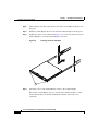
Place the unit in the desired location. You can mount it in a rack for your
convenience, or place it on a solid, stable surface. If you do not plan to install the
unit in an equipment rack, proceed to the “Installing the Chassis on a Tabletop”
section on page 3-11.
Racks are marked in vertical increments of 1.75 inches (4.44 cm). Each increment
is referred to as a rack unit (RU). A 1-RU device is 1.75 inches (4.44 cm) tall.
Warning
To prevent bodily injury when mounting or servicing this unit in a rack, you
must take special precautions to ensure that the system remains stable. The
following guidelines are provided to ensure your safety:
•
This unit should be mounted at the bottom of the rack if it is the only unit in the rack.
•
When mounting this unit in a partially filled rack, load the rack from the bottom to the
top with the heaviest component at the bottom of the rack.
•
If the rack is provided with stabilizing devices, install the stabilizers before mounting
or servicing the unit in the rack. Statement 1006
Cisco Content Engine 511 and 566 Hardware Installation Guide
3-2
OL-5756-01
Chapter 3
Installing the Content Engine
Installing a CE-511 or CE-566 Unit
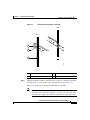
Installing the Chassis in a 2-Post Rack
The Content Engine mounts to two rack posts with brackets that attach to the sides
of the chassis. These brackets are for a 19-inch (48.26-cm) equipment rack and
require four rack screws in each bracket. (See Figure 3-1.)
Rack-Mount Brackets
Orientation for 19-inch rack
124554
Figure 3-1
Cisco Content Engine 511 and 566 Hardware Installation Guide
OL-5756-01
3-3
Chapter 3
Installing the Content Engine
Installing a CE-511 or CE-566 Unit
To install a Content Engine in a 2-post rack, follow these steps:
Step 1
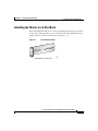
Figure 3-2
Attach a bracket to one side of the chassis, aligning the front flange of the bracket
with the hash mark on the side of the chassis. (See Figure 3-2.)
Installing the Chassis in the Rack
124555
Rear
Front
Step 2
Attach a second bracket to the opposite side of the chassis in the same manner.
Step 3
After you secure the brackets to the chassis, rack-mount the chassis by securing
the brackets to two posts or mounting strips in the rack. You need two people to
install the chassis in the rack—one person to hold the chassis and one person to
secure it to the rack.
The inlet and exhaust ports for cooling air are located in the front and rear of the
chassis, respectively; therefore, multiple Content Engines can be stacked with
little or no vertical clearance.
Installing the Chassis in a 4-Post Rack
Figure 3-3 shows the items that you need to install the Content Engine in a 4-post
rack. If any items are missing or damaged, contact your place of purchase.
Cisco Content Engine 511 and 566 Hardware Installation Guide
3-4
OL-5756-01
Chapter 3
Installing the Content Engine
Installing a CE-511 or CE-566 Unit
Figure 3-3
Rack Installation Kit
1
2
3
4
5
83198
6
7
Note
1
Slide rail assemblies (2)
2
M3.5 screws with lock washers (3)
3
M4 screws (6)
4
M6 screws (10)
5
Clip nuts (10)
6
Cage nuts (10)
7
Cage nut insertion tool (1)
The right and left slide rails are identical.
Cisco Content Engine 511 and 566 Hardware Installation Guide
OL-5756-01
3-5
Chapter 3
Installing the Content Engine
Installing a CE-511 or CE-566 Unit
To install the CE-511 and CE-566 in the 4-post rack, follow these steps:
Step 1
Select a 1-RU-size location in the rack. Starting with the right front side of the
rack (as viewed from the front of the Content Engine), install a clip nut or cage
nut in the top and bottom positions of the 1-RU location that you selected (see
Figure 3-4) and then install a clip nut or cage nut in the corresponding positions
on the rear of the rack. Repeat this step for the left front side of the rack and the
corresponding location on the rear of the rack.
Figure 3-4
Installing Clip Nuts or Cage Nuts
2
83200
1
1
Step 2
Cage nuts
2
Clip nuts
Remove the inner slide rails from the slide rail assemblies by pressing the release
latches on the sides of the slide rail assemblies. (See Figure 3-5.)
Cisco Content Engine 511 and 566 Hardware Installation Guide
3-6
OL-5756-01
Chapter 3
Installing the Content Engine
Installing a CE-511 or CE-566 Unit
Figure 3-5
Removing the Inner Slide Rail
3
2
83202
1
Step 3
1
Slide rail assembly
3
Inner slide rail
2
Release latch
Place an inner slide rail at the alignment marker (labeled 1 in Figure 3-6) as
indicated by the arrow on the side of the Content Engine. Use two M4 screws to
secure the inner slide rail to the Content Engine.
Repeat this step to attach the other inner slide rail to the Content Engine.
Cisco Content Engine 511 and 566 Hardware Installation Guide
OL-5756-01
3-7
Chapter 3
Installing the Content Engine
Installing a CE-511 or CE-566 Unit
Figure 3-6
Attaching the Inner Slide Rail to the Content Engine
83203
1
Step 4
Insert the tab (labeled 1 in Figure 3-7) on the rear of the slide rail assembly
through the center hole between the two clip nuts or cage nuts on the rear flange.
Cisco Content Engine 511 and 566 Hardware Installation Guide
3-8
OL-5756-01
Chapter 3
Installing the Content Engine
Installing a CE-511 or CE-566 Unit
Figure 3-7
Attaching the Slide Rails to the Rack
Front
Rear
1
2
83199
3
Step 5
1
Tab
3
Rear flange
2
Adjustment screw
Align the slide rail assembly to the front flange on the rack, and insert and tighten
two M6 screws to secure the slide rail to the front flange. (See Figure 3-7.)
Repeat Step 4 and Step 5 to install the other slide rail assembly.
Note
If it is necessary to adjust the length of the slide rail, loosen the
adjustment screw (labeled 2 in Figure 3-7) on the rear of the slide rail;
then adjust the length of the slide rail and tighten the adjustment screw.
Cisco Content Engine 511 and 566 Hardware Installation Guide
OL-5756-01
3-9
Chapter 3
Installing the Content Engine
Installing a CE-511 or CE-566 Unit
Step 6
Align and insert the inner slide rails into the slide rail assemblies until they lock
into place.
Step 7
Slide the Content Engine into the rack until the Content Engine locks into place.
Step 8
Tighten the captive screw (labeled 1 in Figure 3-8) on each side of the front of the
Content Engine to secure the Content Engine to the rack.
Inserting the Inner Slide Rails
83201
Figure 3-8
1
Step 9
Attach the power cords and the Ethernet cables to the Content Engine.
Because the Content Engine does not contain cable retention brackets or cable
strain relief brackets, you must first bundle the external cables before you
route them.
Cisco Content Engine 511 and 566 Hardware Installation Guide
3-10
OL-5756-01
Chapter 3
Installing the Content Engine
Installing a CE-511 or CE-566 Unit
Note
Leave enough slack in the cables to allow for sliding the Content Engine
in or out of the rack.
To remove the Content Engine from the rack, reverse these instructions. Store
these installation instructions with your Content Engine documentation for
future use.
Installing the Chassis on a Tabletop
When you install a Content Engine on a workbench or tabletop, ensure that the
surface is clean and in a safe location and that you have considered the following:
•
The chassis should be installed off the floor. (Dust that accumulates on the
floor is drawn into the interior of the chassis by the cooling fans. Excessive
dust inside the Content Engine can cause overtemperature conditions and
component failures.)
•
There must be approximately 19 inches (48.26 cm) of clearance at the front
and rear of the chassis for accessing network cables or equipment.
•
The Content Engine must receive adequate ventilation (it is not being
installed in an enclosed cabinet where ventilation is inadequate).
Follow these steps to install the Content Engine on a workbench or tabletop:
Step 1
Remove any debris and dust from the tabletop or workbench, as well as from the
surrounding area. Also make sure that your path between the Content Engine and
its new location is unobstructed.
Step 2
Attach the rubber feet to the bottom of the chassis. The rubber feet have an
adhesive backing. Peel the protective tape off the adhesive and stick the feet to the
bottom of a clean chassis surface. Place one foot in each corner.
Step 3
Place the chassis on the tabletop or workbench.
Step 4
Ensure that no exhaust air from other equipment will be drawn into the chassis.
Also, ensure that there is adequate clearance at the front and rear of the chassis.
Cisco Content Engine 511 and 566 Hardware Installation Guide
OL-5756-01
3-11
Chapter 3
Installing the Content Engine
Connecting Cables
Connecting Cables
Follow these steps to connect network, console, and SCSI cables to the
Content Engine.
Note
The SCSI cable is part of the Cisco Storage Array accessory kit. If you did not
order the Cisco Storage Array, you did not receive a SCSI cable.
Step 1
For network connections, insert a Category 5 UTP cable into the Ethernet 1 or
Ethernet 2 receptacle on the Content Engine back panel. (See Figure 3-9.)
Step 2
Connect the other end of the network cable to a hub or switch in your
network.
Step 3
For console connections, plug the serial cable into the serial port on the
Content Engine back panel.
Step 4
Connect the other end of the console cable to a console or a communications
server.
Step 5
If you are using a Cisco Storage Array as an external storage device, attach the
SCSI cable to the SCSI LVD port.
Caution
Note
Step 6
Make sure to tighten the jackscrews on the SCSI cable.
SCSI port is available only on CE-566 model.
Connect the other end of the SCSI cable to the appropriate port on the
Storage Array.
For further information about the Cisco Storage Array, refer to the
Cisco Storage Array Installation and Configuration Guide publications.
Cisco Content Engine 511 and 566 Hardware Installation Guide
3-12
OL-5756-01
Chapter 3
Installing the Content Engine
Connecting Power and Booting the System
Figure 3-9
CE-511 and CE-566 Back Panel Ports and Receptacles
2
3
4
115773
1
8
7
5
6
1
AC power receptacle
2
Mouse connector
3
Keyboard connector
4
Ethernet 1 receptacle
5
Ethernet 2 receptacle
6
USB ports (not supported)
7
Video connector
8
Serial connector
Note
Cisco ACNS software does not support the use of a keyboard or mouse (PS/2 or
USB) with the Content Engine. However, keyboard and mouse are supported by
the BIOS for power-on self-test (POST), and the configuration/setup utility.
Connecting Power and Booting the System
Follow these steps to connect power to the Content Engine:
Step 1
Review the information in the “Safety Warnings” section on page 2-1.
Step 2
Plug the AC power cord into the power cord receptacle at the rear of the
Content Engine. (See Figure 3-9.)
Step 3
Connect the other end of the power cord to a power source at your installation site.
Cisco Content Engine 511 and 566 Hardware Installation Guide
OL-5756-01
3-13
Chapter 3
Installing the Content Engine
Checking the LEDs
Step 4
Power up all externally connected devices.
Step 5
Press the power control button on the front of the Content Engine.
The system should begin booting. Once the operating system boots, you are ready
to initialize the basic software configuration. (Refer to the software configuration
guide or user guide that shipped with your system.)
Note
Note
While the Content Engine is powering up, the green power on LED on the
front of the Content Engine is on.
You can install a circular disk over the power control button to prevent accidental
manual power down. This disk, known as the power control button shield, comes
with the Content Engine.
Checking the LEDs
When the Content Engine is up and running, observe the front panel LEDs.
(See the “LED Indicators” section on page 1-8 to verify that your system is
operating properly.)
Removing or Replacing a Content Engine
Warning
Before working on a system that has an on/off switch, turn OFF the power and
unplug the power cord. Statement 1
Warning
Ultimate disposal of this product should be handled according to all national
laws and regulations. Statement 1040
Cisco Content Engine 511 and 566 Hardware Installation Guide
3-14
OL-5756-01
Chapter 3
Installing the Content Engine
Removing or Replacing a Content Engine
To remove a Content Engine from your network, power it down, disconnect the
power cords and network cables, and physically remove the chassis from the rack.
The Content Engine is in constant communication with the router on your
network; thus, when the router notices that the Content Engine is no longer
responding to it, the router stops sending requests to the Content Engine. This is
transparent to users. If other Content Engines are attached to the router, the router
continues sending requests to the other Content Engines.
When you remove a Content Engine, the pages that were cached on that device
are no longer available to the router or other Content Engines. Thus, you might
see an increase in outgoing web traffic that might have otherwise been fulfilled by
the Content Engine that you are removing. However, after a time, the router and
other Content Engines redistribute the load of web traffic.
If you remove the last Content Engine from your network, you can also disable
Content Engine support on the router. However, this is not necessary; having
Content Engine support enabled when there are no Content Engines attached has
no effect on the router’s performance.
To replace a Content Engine, remove it from the network. Then, install a new
Content Engine and configure it using the same configuration parameters
(IP address, and so forth) that you used for the removed Content Engine.
Cisco Content Engine 511 and 566 Hardware Installation Guide
OL-5756-01
3-15
Chapter 3
Installing the Content Engine
Removing or Replacing a Content Engine
Cisco Content Engine 511 and 566 Hardware Installation Guide
3-16
OL-5756-01
C H A P T E R
4
Installing Hardware Options
This chapter provides basic instructions for installing hardware options in the
Content Engine. These instructions are intended for technicians who are
experienced with setting up Cisco Content Engine hardware.
This chapter contains the following topics:
•
Removing the Cover and Bezel, page 4-1
•
Installing Adapters, page 4-3
•
Working with Hard Disk Drives, page 4-12
•
Completing the Installation, page 4-16
Removing the Cover and Bezel
Warning
Before working on a system that has an on/off switch, turn OFF the power and
unplug the power cord. Statement 1
Complete the following steps to remove the Content Engine cover:
Step 1
Review the information in the “Safety Warnings” section on page 2-1, and the
“Safety Guidelines” section on page 2-4.
Step 2
Power down the Content Engine and all attached devices. Disconnect the power
cord and all external cables.
Step 3
Loosen the two captive screws (1) on the rear of the cover. (See Figure 4-1.)
Cisco Content Engine 511 and 566 Hardware Installation Guide
OL-5756-01
4-1
Chapter 4
Installing Hardware Options
Removing the Cover and Bezel
Figure 4-1
Removing the Content Engine Cover
115802
1
Step 4
Caution
Step 5
Slide the cover back; then lift it up and off the Content Engine.
For proper cooling and airflow, replace the cover before turning on the
Content Engine. Operating the Content Engine for extended periods (over
30 minutes) with the cover removed might damage Content Engine components.
Remove the bezel as shown in Figure 4-2.
a.
Press the release tabs on the bezel and pull the bezel away from the
Content Engine.
b.
Store the bezel in a safe place.
Cisco Content Engine 511 and 566 Hardware Installation Guide
4-2
OL-5756-01
Chapter 4
Installing Hardware Options
Installing Adapters
Removing the Content Engine Bezel
124004
Figure 4-2
Installing Adapters
This section provides general information about the system board, riser card,
adapter and PCI-X slot configuration specifications, and contains the following
adapter installation procedures:
•
Installing an MPEG Decoder Adapter, page 4-5
•
Preparing and Installing a Fibre Channel Adapter, page 4-8
Cisco Content Engine 511 and 566 Hardware Installation Guide
OL-5756-01
4-3
Chapter 4
Installing Hardware Options
Installing Adapters
Before you install adapters, review the following:
•
The Content Engine comes with two Peripheral Component
Interconnect-Extended (PCI-X) adapter slots. PCI-X slot 1 is located on the
adapter support bracket with the riser card. PCI-X slot 2 is located on the
system board. To access the PCI-X slot 1 connector, you must first remove
the adapter support bracket. (See Figure 4-4.)
– You can install either a Fibre Channel adapter or an MPEG A/V decoder
adapter in PCI-X slot 1. (This slot is labeled “PCI 1” on the back of the
Content Engine.)
– The CE-566 has a SCSI adapter installed in PCI-X slot 2 (PCI 2). This
adapter is not user-replaceable.
Caution
•
Locate the documentation that comes with the adapter and follow those
instructions in addition to the instructions in this chapter.
•
The system scans PCI-X slots to assign system resources. By default the
system tries to boot from the CD-ROM. If the CD-ROM is not present, the
system boots from the integrated flash device.
When you handle static-sensitive devices, take precautions to avoid damage from
static electricity. For details on handling these devices, see the “Protecting
Against Electrostatic Discharge” section on page 2-6.
Cisco Content Engine 511 and 566 Hardware Installation Guide
4-4
OL-5756-01
Chapter 4
Installing Hardware Options
Installing Adapters
Installing an MPEG Decoder Adapter
Complete the following steps to install an MPEG decoder adapter.
Note
The illustrations in this document might differ slightly from your hardware.
Step 1
Review the safety information in the “Safety Guidelines” section on page 2-4.
Step 2
Power down the Content Engine and peripheral devices.
Step 3
Disconnect the power cord and then all external cables from the Content Engine.
Step 4
Remove the Content Engine cover.
Note
Step 5
It might be easier to route the cables before you install the adapter.
Loosen the captive screw (labeled 4 in Figure 4-3) located on the rear of the
Content Engine adjacent to PCI-X slot 1 and remove the expansion slot cover.
Note
PCI expansion slot covers must be installed on all vacant slots. This
maintains the electronic emissions characteristics of the Content Engine
and ensures proper cooling of Content Engine components.
Cisco Content Engine 511 and 566 Hardware Installation Guide
OL-5756-01
4-5
Chapter 4
Installing Hardware Options
Installing Adapters
Removing the Expansion Slot Cover
124478
Figure 4-3
1
2
4
3
1
Expansion slot cover (slot 2)
2
Expansion slot cover (slot 1)
3
Captive screw
4
Riser card assembly
Step 6
Remove the riser card (labeled 1 in Figure 4-4) from the system board to access
the expansion slot.
Cisco Content Engine 511 and 566 Hardware Installation Guide
4-6
OL-5756-01
Chapter 4
Installing Hardware Options
Installing Adapters
Figure 4-4
Installing an Adapter in PCI-X Slot 1
1
2
3
4
124479
5
6
1
Riser card
2
PCI-X slot 2 connector
3
PCI-X slot 1 connector
4
Adapter support bracket
5
Adapter
6
PCI-X riser card connector
Cisco Content Engine 511 and 566 Hardware Installation Guide
OL-5756-01
4-7
Chapter 4
Installing Hardware Options
Installing Adapters
Step 7
Touch the static-protective package containing the adapter to any unpainted metal
surface on the Content Engine and then remove the adapter from the
static-protective package. Avoid touching the components and gold-plated edge
connectors on the adapter.
Step 8
Place the adapter, component-side up, on a flat, static-protective surface and set
any jumpers or switches as described by the adapter manufacturer, if necessary.
Caution
When you install an adapter in the Content Engine, be sure that it is completely
and correctly seated in the PCI expansion slot before you power up the
Content Engine. Incomplete insertion might cause damage to the system board or
the adapter.
Step 9
To install the adapter, carefully grasp the adapter by its top edge or upper corners,
align it with the PCI-X slot 1 connector (labeled 2 in Figure 4-4), and then press
the adapter firmly into the expansion slot.
Step 10
Reinstall the riser card. Make sure that the riser card is fully seated in the riser
card connector (labeled 5 in Figure 4-4) on the system board.
Step 11
Tighten the captive screw for expansion slot 1.
Step 12
Connect the required cables to the adapter.
Step 13
If you have other hardware options to install, do so now; otherwise, go to the
“Completing the Installation” section on page 4-16.
Preparing and Installing a Fibre Channel Adapter
Fibre Channel is a high-speed data transport technology used for mass storage and
networking. Fibre Channel technology is outlined in the SCSI-3 Fibre Channel
Protocol (SCSI-FCP).
The Fibre Channel adapter uses a multimode shortwave optical interface for
distances up to 1640 feet (500 meters). It is a 2-gigabit (Gb) Fibre Channel device
that supports data transfer rates up to 200 megabytes per second (MBps) half
duplex and 400 MBps full duplex on optical interfaces.
Cisco Content Engine 511 and 566 Hardware Installation Guide
4-8
OL-5756-01
Chapter 4
Installing Hardware Options
Installing Adapters
Preparing to Install the Adapter
Before you begin the installation, do these tasks:
•
Read the “Fiber-Optic Cabling Guidelines for the Fibre Channel Adapter”
section.
•
Read the “Tools and Parts Required” section.
•
Write down the serial number for future reference.
Fiber-Optic Cabling Guidelines for the Fibre Channel Adapter
To avoid damage to your fiber-optic cables, follow these guidelines:
•
Do not route the cable along a folding cable management arm.
•
When attaching fiber-optic cables to a Fibre Channel device on slide rails,
leave enough slack in the cables so that they do not bend to a radius smaller
than 1.5 in. (38 mm) when extended or become pinched when retracted.
•
Route the cable away from places where it can snag on other Fibre Channel
devices in the rack.
•
Do not overtighten the cable straps or bend the cables to a radius smaller than
1.5 in. (38 mm).
•
Do not put excess weight on the cable at the connection point and be sure that
the cable is well supported.
Tools and Parts Required
To install the Fibre Channel adapter in your system, you need the following items:
•
Small Phillips screwdriver
•
Logical Cable (LC)-LC Fibre Channel cable (this cable is not provided by
Cisco Systems; you must order it separately)
Cisco Content Engine 511 and 566 Hardware Installation Guide
OL-5756-01
4-9
Chapter 4
Installing Hardware Options
Installing Adapters
Installing the Fibre Channel Adapter
To install the Fibre Channel adapter, follow these steps:
Step 1
Check the system board and locate the correct PCI-X slot for the Fibre Channel
card.
Step 2
Power down any connected peripheral devices and then power down the Content
Engine.
Step 3
Disconnect the power cords.
Step 4
Remove the cover. (See the “Removing the Cover and Bezel” section on
page 4-1.)
Step 5
Remove the expansion slot cover. (See Figure 4-3.)
Step 6
Align the adapter with the slot 2 connector on the riser card. Carefully press the
adapter into the expansion slot until it is fully seated and secure. (See Figure 4-4.)
Step 7
Reinstall the riser card. Make sure that the riser card is fully seated in the riser
card connector on the system board.
Step 8
Connect one end of an LC-LC Fibre Channel cable to the optical interface
connector on the Fibre Channel adapter card. Connect the other end to a Fibre
Channel device.
Step 9
Carefully install and secure the cover. (See the “Completing the Installation”
section on page 4-16.)
Step 10
Connect the power cables.
Step 11
Power on all external Fibre Channel devices; then power on the Content Engine.
Step 12
Verify the installation by checking the LEDs. (See Table 1-6 on page 1-10.)
Troubleshooting the Fibre Channel Adapter Installation
Three types of adapter installation problems might cause your Fibre Channel
adapter to function incorrectly:
•
Hardware problems
•
System configuration problems
•
Fibre Channel problems
Cisco Content Engine 511 and 566 Hardware Installation Guide
4-10
OL-5756-01
Chapter 4
Installing Hardware Options
Installing Adapters
Hardware Problems
Take the following actions to determine if your installation problem is caused by
the hardware:
1.
Verify that all adapters are installed securely.
2.
Verify that all cables are attached securely to the correct connectors. Be sure
that one end of the LC-LC Fibre Channel cable is attached to the optical
interface connector and that the other end is connected to the Fibre Channel
device.
3.
Verify that the Fibre Channel adapter is installed correctly and is fully seated
in the correct expansion slot.
4.
Verify that all peripheral devices are turned on.
System Configuration Problems
Verify that the Fibre Channel adapter card is installed in the correct PCI-X slot. If
you still have a system configuration problem, contact Cisco technical support for
assistance. (See the “Obtaining Technical Assistance” section on page -xxii.)
Fibre Channel Problems
To determine if your installation problem is caused by an attached Fibre Channel
device, perform the following tasks:
1.
Verify that all of the Fibre Channel devices were turned on before you turned
on the Content Engine.
2.
Ensure that all cables are connected properly.
3.
Verify that you configured your RAID storage subsystems using the utilities
provided by the manufacturer.
4.
If your Fibre Channel switch supports zoning, make sure that your peripheral
device is configured to the same switch zone as the Fibre Channel adapter.
Cisco Content Engine 511 and 566 Hardware Installation Guide
OL-5756-01
4-11
Chapter 4
Installing Hardware Options
Working with Hard Disk Drives
Working with Hard Disk Drives
This section describes how to install a hard disk drive in the Content Engine. The
CE-511 requires a Serial Advanced Technology Attachment (SATA) hard disk
drive. CE-566 supports two 1-inch (2.54-cm) slim 3.5-inch (8.89-cm) LVD hard
disk drives. The CE-566 requires a SCSI hard disk drive.
Installing a Hard Disk Drive in the CE-511
To install a simple-swap SATA hard disk drive in a bay, complete the following
steps.
Note
All hard disk drives being used in the Content Engine should have the same
throughput speed rating. Mixing hard disk drives with different speed ratings will
cause all hard disk drives to operate at the lower throughput speed.
Note
If your Content Engine has only one hard disk drive, install it in the left drive bay.
Caution
To maintain proper system cooling, do not operate the Content Engine for more
than 10 minutes without either a hard disk drive or a filler panel installed in
each bay.
Step 1
Inspect the new drive for any signs of damage.
Step 2
Review the information in the “Safety Warnings” section on page 2-1, and the
“Safety Guidelines” section on page 2-4.
Step 3
Power down the Content Engine and peripheral devices, and disconnect the power
cord and all external cables.
Step 4
Press the release tabs on the bezel and pull the bezel away from the
Content Engine. (See Figure 4-2.)
Cisco Content Engine 511 and 566 Hardware Installation Guide
4-12
OL-5756-01
Chapter 4
Installing Hardware Options
Working with Hard Disk Drives
Step 5
Install the hard disk drive in the bay.
a.
Align the drive assembly (see Figure 4-5) with the guide rails in the bay.
b.
Gently push the drive assembly into the drive bay until the drive connects to
the backplane.
c.
Check the hard disk drive status LED to verify that the hard disk drive is
operating properly.
If the amber hard disk drive status LED for a drive is lit continuously, that
individual drive is faulty and needs to be replaced. If the green hard disk drive
activity LED is flashing, the drive is being accessed.
Installing a SATA Hard Disk on CE-511
124005
Figure 4-5
Hard disk drive
SATA hard disk
drive connector
Cisco Content Engine 511 and 566 Hardware Installation Guide
OL-5756-01
4-13
Chapter 4
Installing Hardware Options
Working with Hard Disk Drives
Installing a Hard Disk Drive in the CE-566
To install a SCSI hard disk drive in CE-566, complete the following steps.
Note
All hard disk drives being used in the Content Engine should have the same
throughput speed rating. Mixing hard disk drives with different speed ratings will
cause all hard disk drives to operate at the lower throughput speed.
Note
If your Content Engine has only one hard disk drive, install it in the left drive bay.
Note
To maintain proper system cooling, do not operate the Content Engine for more
than 10 minutes without either a hard disk drive or a filler panel installed in
each bay.
Step 1
Inspect the new drive for any signs of damage.
Step 2
Review the information in the “Safety Warnings” section on page 2-1, and the
“Safety Guidelines” section on page 2-4.
Step 3
Power down the Content Engine and peripheral devices, and disconnect the power
cord and all external cables.
Step 4
Press the release tabs on the bezel and pull the bezel away from the
Content Engine. (See Figure 4-2.)
Step 5
Slide the drive tray out of the Content Engine.
Step 6
Position the hard disk drive on the tray. (See Figure 4-6.)
Step 7
Secure the hard disk drive using screws.
Step 8
Slide the tray back into the Content Engine.
Step 9
Connect the power and signal cables to the drive.
Step 10
Replace the bezel.
Cisco Content Engine 511 and 566 Hardware Installation Guide
4-14
OL-5756-01
Chapter 4
Installing Hardware Options
Working with Hard Disk Drives
Installing a SCSI Hard Disk on CE-566
124895
Figure 4-6
1
2
3
2
1
SCSI hard disk drive
3
Hard disk drive tray
2
Screws
Cisco Content Engine 511 and 566 Hardware Installation Guide
OL-5756-01
4-15
Chapter 4
Installing Hardware Options
Completing the Installation
Assigning SCSI IDs
When you replace a SCSI disk drive in a CE-566, you must assign SCSI IDs 0 and
1 to the disk drives. The SCSI IDs are assigned by placing or removing jumpers
on the disk drive SCSI ID pins.
Note
The disk drives have a label on the lower side that identifies the pins. You can
locate the pins corresponding to SCSI ID bit 0 by referring to this label.
Assign SCSI ID 0 to the disk drive in drive bay 2 (located below the flash memory
card on right hand side of your Content Engine) by removing any jumpers from
the SCSI ID pins. (Other jumpers should be set the same as the jumper settings on
the drive that is being replaced.)
Assign SCSI ID 1 to the disk drive in drive bay 1 (located below the CD-ROM
drive) by placing a jumper on the pins corresponding to SCSI ID bit 0.
To check whether the configuration is correct, refer to the boot time messages on
the device console. For example:
Attached scsi disk sda at scsi0, channel 0, id 0, lun 0
Attached scsi disk sdb at scsi0, channel 0, id 1, lun 0
Completing the Installation
To complete your installation, reinstall the bezel, reinstall the Content Engine
cover, and reconnect all cables that you disconnected earlier. Follow the
instructions in this section.
Caution
To maintain proper cooling and airflow, install the Content Engine cover before
turning on the Content Engine. Operating the Content Engine for extended
periods (over 30 minutes) with the Content Engine cover removed might damage
Content Engine components.
Cisco Content Engine 511 and 566 Hardware Installation Guide
4-16
OL-5756-01
Chapter 4
Installing Hardware Options
Completing the Installation
Installing the Content Engine Cover and Bezel
Complete the following steps to install the Content Engine cover and bezel:
Step 1
Install the cover by placing it into position and sliding it forward. Then tighten
the captive screws (labeled 1 in Figure 4-7).
Caution
Before sliding the cover forward, make sure that the cover will properly engage
the ledge at the front of the Content Engine.
Step 2
Install the bezel.
a.
Align the hooks on the bottom of the bezel with the Content Engine.
b.
Press the bezel toward the Content Engine until it clicks into place.
Cisco Content Engine 511 and 566 Hardware Installation Guide
OL-5756-01
4-17
Chapter 4
Installing Hardware Options
Completing the Installation
Figure 4-7
Installing the Content Engine Cover
115802
1
Step 3
Install the Content Engine in the rack. See the “Installing a CE-511 or CE-566
Unit” section on page 3-2 for instructions.
Step 4
Connect all external cables and the power cord to the Content Engine, and then
plug the power cord into a properly grounded electrical outlet.
Cisco Content Engine 511 and 566 Hardware Installation Guide
4-18
OL-5756-01
C H A P T E R
5
Troubleshooting the System Hardware
If your system is not working as expected, begin troubleshooting using the
procedures in this chapter. This chapter guides you through some initial checks
and procedures that can solve basic system problems.
This chapter contains the following sections:
•
Checking the Basics, page 5-1
•
Checking Connections and Switches, page 5-2
Checking the Basics
The following procedure leads you through the checks necessary to solve some
basic system problems:
Step 1
Was an alert message issued by the system software?
Yes. Check the component named in the alert message.
No. Go to Step 2.
Step 2
Visually inspect the chassis. Is the system wet or damaged?
Yes. Liquid spills, splashes, and excessive humidity can cause damage to the
system. If an external device such as an external drive gets wet, contact your
service representative for instructions. (See the “Obtaining Technical Assistance”
section on page xxii.)
Cisco Content Engine 511 and 566 Hardware Installation Guide
OL-5756-01
5-1
Chapter 5
Troubleshooting the System Hardware
Checking Connections and Switches
If the chassis was dropped or damaged while being moved, you should check the
system to see if it functions properly. If an external device attached to the system
is dropped or damaged, contact your service representative for instructions. (See
the “Obtaining Technical Assistance” section on page xxii.)
No. Go to Step 3.
Step 3
Perform the steps in the “Checking Connections and Switches” section on
page 5-2.
Is the problem resolved?
Yes. The power to the system was faulty, or the connections to the system were
loose. You have fixed the problem.
No. Go to Step 4.
Step 4
Verify the settings in the system setup program. For details, see the software
configuration guide that shipped with your system.
Did the system complete the boot routine?
Yes. The system configuration information was incorrect. You have fixed the
problem.
No. Call your service representative. (See the “Obtaining Technical Assistance”
section on page xxii.)
Checking Connections and Switches
Improperly set switches and controls and loose or improperly connected cables
are the most likely source of problems for the chassis or other external equipment.
A quick check of all the switches, controls, and cable connections can easily
solve these problems. (See Figure 1-5 and Figure 1-6 for the location of front
panel controls and indicators. See Figure 1-9 for the location of back panel
connections on the system.)
Cisco Content Engine 511 and 566 Hardware Installation Guide
5-2
OL-5756-01
Chapter 5
Troubleshooting the System Hardware
Checking Connections and Switches
To check all the connections and switches, perform the following steps:
Step 1
Power down the system, including any attached peripherals such as external
drives. Disconnect all the power cables from their electrical outlets.
Step 2
If the system is connected to a power strip (or power distribution unit), turn the
power strip off and then on again.
Is the power strip receiving power?
Yes. Go to Step 5.
No. Go to Step 3.
Step 3
Plug the power strip into another electrical outlet.
Is the power strip receiving power?
Yes. The original electrical outlet probably does not function. Use a different
electrical outlet.
No. Go to Step 4.
Step 4
Plug a system that you know works into the electrical outlet.
Does the system receive power?
Yes. The power strip is probably not functioning properly. Use another power
strip.
No. Go to Step 5.
Step 5
Reconnect the system to the electrical outlet or power strip.
Make sure that all connections fit tightly together.
Step 6
Power up the system.
Is the problem resolved?
Yes. The connections were loose. You have fixed the problem.
No. Call your service representative. (See the “Obtaining Technical Assistance”
section on page xxii.)
Cisco Content Engine 511 and 566 Hardware Installation Guide
OL-5756-01
5-3
Chapter 5
Troubleshooting the System Hardware
Checking Connections and Switches
Cisco Content Engine 511 and 566 Hardware Installation Guide
5-4
OL-5756-01
C H A P T E R
6
Maintaining the Content Engine
Proper use of preventive maintenance procedures can keep the Content Engine in
top operating condition and minimize the need for costly, time-consuming service
procedures. This chapter contains maintenance procedures that you should
perform regularly.
This chapter covers the tasks required for maintaining a Content Engine or a
Content Engine farm:
•
Maintaining Your Site Environment, page 6-1
•
Using Power Protection Devices, page 6-7
Maintaining Your Site Environment
An exhaust fan in the power supply cools the power supply and system by drawing
air in through various openings in the system and blowing it out the back.
However, the fan also draws dust and other particles into the system, causing
contaminant buildup, which results in an increase in the system’s internal
temperature and interferes with the operation of various system components.
To avoid these conditions, we recommend keeping your work environment clean
to reduce the amount of dust and dirt around the system, thereby reducing the
amount of contaminants drawn into the system by the power supply fan.
This section discusses various environmental factors that can adversely affect
system performance and longevity.
Cisco Content Engine 511 and 566 Hardware Installation Guide
OL-5756-01
6-1
Chapter 6
Maintaining the Content Engine
Maintaining Your Site Environment
Temperature
Temperature extremes can cause a variety of problems, including premature aging
and failure of chips or mechanical failure of devices. Extreme temperature
fluctuations can cause chips to become loose in their sockets and can cause
expansion and contraction of disk drive platters, resulting in read or write data
errors.
To minimize the negative effects of temperature on system performance, follow
these guidelines:
•
Ensure that the system is operated in an environment no colder than 50°F
(10°C) or hotter than 95°F (35°C).
•
Ensure that the system has adequate ventilation. Do not place it within a
closed-in wall unit or on top of cloth, which can act as insulation. Do not
place it where it will receive direct sunlight, particularly in the afternoon. Do
not place it next to a heat source of any kind, including heating vents during
winter.
Adequate ventilation is particularly important at high altitudes. System
performance may not be optimum when the system is operating at high
temperatures as well as high altitudes.
•
Make sure that all slots and openings on the system remain unobstructed,
especially the fan vent on the back of the system.
•
Clean the system at regular intervals to avoid any buildup of dust and debris,
which can cause a system to overheat.
•
If the system has been exposed to abnormally cold temperatures, allow a
2-hour warm-up period to bring it up to normal operating temperature before
turning it on. Failure to do so may cause damage to internal components,
particularly the hard disk drive.
•
If intermittent system failures are noticed, try reseating any socketed chips,
which might have become loose because of temperature fluctuations.
Cisco Content Engine 511 and 566 Hardware Installation Guide
6-2
OL-5756-01
Chapter 6
Maintaining the Content Engine
Maintaining Your Site Environment
Humidity
High-humidity conditions can cause moisture migration and penetration into the
system. This moisture can cause corrosion of internal components and
degradation of properties such as electrical resistance, thermal conductivity,
physical strength, and size. Extreme moisture buildup inside the system can result
in electrical shorts, which can cause serious damage to the system.
Each system is rated to operate at 8 to 80 percent relative humidity, with a
humidity gradation of 10 percent per hour. Buildings in which climate is
controlled by air conditioning in the warmer months and by heat during the colder
months usually maintain an acceptable level of humidity for system equipment.
However, if a system is located in an unusually humid location, a dehumidifier can
be used to maintain the humidity within an acceptable range.
Altitude
Operating a system at high altitude (low pressure) reduces the efficiency of forced
and convection cooling and can result in electrical problems related to arcing and
corona effects. This condition can also cause sealed components with internal
pressure, such as electrolytic capacitors, to fail or perform at reduced efficiency.
Each system is rated to operate at a maximum altitude of 6998 feet (2133 meters)
and can be stored at a maximum altitude of 15,000 feet (4570 meters).
Dust and Particles
A clean operating environment can greatly reduce the negative effects of dust and
other particles, which act as insulators and interfere with the operation of a
system’s mechanical components. Also, in addition to regular cleaning, you
should follow these guidelines to deter contamination of the system equipment:
•
Do not permit smoking anywhere near the system.
•
Do not permit food or drink near the system.
•
Use dust covers when the system is not in use.
•
Close windows and outside doors to keep out airborne particles.
Cisco Content Engine 511 and 566 Hardware Installation Guide
OL-5756-01
6-3
Chapter 6
Maintaining the Content Engine
Maintaining Your Site Environment
Corrosion
The oil from a person’s fingers or prolonged exposure to high temperature or
humidity can corrode the gold-plated edge connectors and pin connectors on
various devices in the system. This corrosion on system connectors is a gradual
process that can eventually lead to intermittent failures of electrical circuits.
To prevent corrosion, you should avoid touching contacts on boards and cards.
Protecting the system from corrosive elements is especially important in moist
and salty environments, which tend to promote corrosion. Also, as a further
deterrent to corrosion, the system should not be used in extreme temperatures, as
explained in the “Temperature” section on page 6-2.
Electrostatic Discharge
Electrostatic discharge (ESD) results from the buildup of static electricity on the
human body and certain other objects. This static electricity is often produced by
simple movements such as walking across a carpet. ESD is a discharge of a static
electrical charge that occurs when a person whose body contains such a charge
touches a component in the system. This static discharge can cause components,
especially chips, to fail. ESD is a problem particularly in dry environments where
the relative humidity is below 50 percent.
To reduce the effects of ESD, you should observe the following guidelines:
•
Wear a grounding wrist strap. If a grounding wrist strap is unavailable, touch
an unpainted metal surface on the chassis periodically to neutralize any static
charge.
•
Keep components in their antistatic packaging until they are installed.
•
Avoid wearing clothing made of wool or synthetic materials.
Cisco Content Engine 511 and 566 Hardware Installation Guide
6-4
OL-5756-01
Chapter 6
Maintaining the Content Engine
Maintaining Your Site Environment
Electromagnetic and Radio Frequency Interference
Electromagnetic interference (EMI) and radio frequency interference (RFI) from
a system can adversely affect devices such as radio and television (TV) receivers
operating near the system. Radio frequencies emanating from a system can also
interfere with cordless and low-power telephones. Conversely, RFI from
high-power telephones can cause spurious characters to appear on the system’s
monitor screen.
RFI is defined as any EMI with a frequency above 10 kilohertz (kHz). This type
of interference can travel from the system to other devices through the power
cable and power source or through the air like transmitted radio waves. The
Federal Communications Commission (FCC) publishes specific regulations to
limit the amount of EMI and RFI emitted by computing equipment. Each system
meets these FCC regulations.
To reduce the possibility of EMI and RFI, follow these guidelines:
•
Operate the system only with the system cover installed.
•
Ensure that the screws on all peripheral cable connectors are securely
fastened to their corresponding connectors on the back of the system.
•
Always use shielded cables with metal connector shells for attaching
peripherals to the system.
Magnetism
Because they store data magnetically, hard disk drives are extremely susceptible
to the effects of magnetism. Hard disk drives should never be stored near magnetic
sources such as the following:
•
Monitors
•
TV sets
•
Printers
•
Telephones with real bells
•
Fluorescent lights
Cisco Content Engine 511 and 566 Hardware Installation Guide
OL-5756-01
6-5
Chapter 6
Maintaining the Content Engine
Maintaining Your Site Environment
Power Source Interruptions
Systems are especially sensitive to variations in voltage supplied by the AC power
source. Overvoltage, undervoltage, and transients (or spikes) can erase data from
memory or even cause components to fail. To protect against these types of
problems, power cables should always be properly grounded and one or both of
the following methods should be used:
•
Use one of the power protection devices described in the “Using Power
Protection Devices” section on page 6-7.
•
Place the system on a dedicated power circuit (rather than sharing a circuit
with other heavy electrical equipment). In general, do not allow the system to
share a circuit with any of the following:
– Copier machines
– Air conditioners
– Vacuum cleaners
– Space heaters
– Power tools
– Teletype machines
– Adding machines
– Laser printers
– Facsimile machines
– Any other motorized equipment
Besides these appliances, the greatest threats to a system’s supply of power are
surges or blackouts caused by electrical storms. Whenever possible, turn off the
system and any peripherals and unplug them from their power sources
during thunderstorms.
If a blackout occurs—even a temporary one—while the system is turned on, turn
off the system immediately and disconnect it from the electrical outlet. Leaving
the system on may cause problems when the power is restored; all other
appliances left on in the area can create large voltage spikes that can damage
the system.
Cisco Content Engine 511 and 566 Hardware Installation Guide
6-6
OL-5756-01
Chapter 6
Maintaining the Content Engine
Using Power Protection Devices
Using Power Protection Devices
A number of devices are available that protect against power problems such as
power surges, transients, and power failures. The following subsections describe
some of these devices.
Surge Protectors
Surge protectors are available in a variety of types and usually provide a level of
protection commensurate with the cost of the device. Surge protectors prevent
voltage spikes, such as those caused during an electrical storm, from entering a
system through the electrical outlet. Surge protectors, however, do not offer
protection against brownouts, which occur when the voltage drops more than
20 percent below the normal AC line voltage level.
Line Conditioners
Line conditioners go beyond the overvoltage protection of surge protectors. Line
conditioners keep a system’s AC power source voltage at a fairly constant level
and therefore can handle brownouts. Because of this added protection, line
conditioners cost more than surge protectors—up to several hundred dollars.
However, these devices cannot protect against a complete loss of power.
Uninterruptible Power Supplies
Uninterruptible power supply (UPS) systems offer the most complete protection
against variations in power because they use battery power to keep the system
running when AC power is lost. The battery is charged by the AC power while it
is available, so once AC power is lost, the battery can provide power to the system
for a limited amount of time—from 15 minutes to an hour or so—depending on
the UPS system.
Cisco Content Engine 511 and 566 Hardware Installation Guide
OL-5756-01
6-7
Chapter 6
Maintaining the Content Engine
Using Power Protection Devices
UPS systems range in price from a few hundred dollars to several thousand
dollars, with the more expensive units allowing you to run larger systems for a
longer period of time when AC power is lost. UPS systems that provide only
5 minutes of battery power let you conduct an orderly shutdown of the system, but
are not intended to provide continued operation. Surge protectors should be used
with all UPS systems, and the UPS system should be Underwriters Laboratories
(UL) safety-approved.
Cisco Content Engine 511 and 566 Hardware Installation Guide
6-8
OL-5756-01
INDEX
A
C
A/V ports
cables
description 1-12
AC power
receptacle 1-12
AC power cords
connecting 3-13
adapters
description 1-17
installing 4-5
altitude
guidelines 6-3
specifications 1-20
connecting 3-12
cabling requirements
Ethernet standard (note) 1-13
caching
web traffic 1-5
cautions
description of xii
CD eject button
description 1-7
CD-ROM drive LED
description 1-8
Class A warnings 1-22
connections
B
cables 3-12
back panel
LEDs (figure) 1-9
LEDs (table) 1-9
ports (table) 1-12
bays
description 1-17
power 3-13
troubleshooting 5-2
connectors and ports
description 1-11 to 1-15
console
connecting to port 3-12
Content Delivery Network
description 1-5
Cisco Content Engine 511 and 566 Hardware Installation Guide
OL-5756-01
IN-1
Index
Content Engine
E
back panel 1-11
Class A warnings 1-22
front panel 1-7
functional description 1-4
installing 3-2
installing in a 2-post rack 3-3, 3-4
maintaining 6-1
regulatory compliance 1-20
removing or replacing 3-14
control buttons
front panel 1-7
electrical input
specifications 1-19
electromagnetic interference
See EMI
electrostatic discharge
See ESD
EMI
preventing effects of 6-5
environment
maintaining 6-1
ESD
conventions
document xi
preventing damage 2-6, 6-4
Ethernet 1 activity LED 1-9
corrosion
preventing damage 6-4
Ethernet 1 link LED 1-9
Ethernet 1 port 1-12
covers
installing 4-17
Ethernet 2 activity LED 1-9
removing 4-1
Ethernet 2 link LED 1-9
Ethernet 2 port 1-12
Ethernet connections 3-12
D
Ethernet controller 1-2, 1-13
Ethernet ports
dimensions
Content Engine 1-19
cabling requirements (note) 1-13
disk drives. See hard disk drives
connector pinout 1-13
document
description 1-13
conventions xi
expansion bays
description 1-17
dust
preventing damage 6-3
expansion slots
Cisco Content Engine 511 and 566 Hardware Installation Guide
IN-2
OL-5756-01
Index
description 1-17
specifications
for CE-511 1-4
for CE-566 1-4
F
hardware
troubleshooting 5-1
Fibre Channel adapter
connector 1-15
heat dissipation
specifications 1-20
LEDs (table) 1-10
port
humidity
maintenance guidelines 6-3
description 1-12
specifications 1-20
specifications (table) 1-18
front panel
control buttons (table) 1-7
figure 1-7
I
LEDs (figure) 1-8
I/O connectors 1-11
LEDs (table) 1-8
installation
rack 3-6
functional description
Content Engine 1-4
tabletop 3-11
warnings 2-1
H
installing
adapters 4-5
covers 4-17
hard disk controller
hard disk drives 4-12
description 1-17
hard disk drive LED
description 1-8
hard disk drives
assigning SCSI IDs 4-16
L
LEDs
installing 4-12
back panel (figure) 1-9
SCSI 4-12
back panel (table) 1-9
serial ATA 4-12
checking 3-14
Cisco Content Engine 511 and 566 Hardware Installation Guide
OL-5756-01
IN-3
Index
front panel (figure) 1-8
P
front panel (table) 1-8
line conditioners
using 6-7
local-area network
Ethernet 1-2
PCI-X slots 4-4
pinouts, MPEG A/V decoder audio and video
connectors 1-16
ports
and connectors
description 1-11 to 1-15
M
back panel (table) 1-12
Ethernet
magnetism
preventing effects of 6-5
maintenance 6-1 to 6-6
memory specifications
for CE-511 1-4
for CE-566 1-4
microprocessor
description 1-17
MPEG A/V decoder adapter
connectors 1-12, 1-15
installing 4-5
connecting 3-12
serial
connecting 3-12
power
connecting to system 3-13
power control button
description 1-7
power control button shield 3-14
power LED
description 1-8
power receptacles
description 1-12
N
power requirement 1-19
power source interruptions
network
removing Content Engine from 3-14
noise emissions
specifications 1-20
preventing damage from 6-6
power supplies
receptacles 1-12
specifications 1-18
using uninterruptible 6-7
Cisco Content Engine 511 and 566 Hardware Installation Guide
IN-4
OL-5756-01
Index
SCSI LVD ports
R
connector pinout 1-14
rack installation 3-6
description 1-14
rack-mount brackets
for Storage Array 1-12
figure 3-3
rack-mount kit
serial ATA hard disk drive 4-12
serial ports
contents of 3-5
connector pinout 1-14
radio frequency interference. See RFI
receptacles
description 1-12, 1-13
shield
power 1-12
regulatory compliance 1-20
power control button 3-14
site environment
removing or replacing
Content Engine 3-14
maintenance factors 6-1
slots
reset button
description 1-7
specifications 1-17
specifications
RFI
preventing effects of 6-5
Content Engine (table) 1-17
Storage Array
connecting to 3-12
surge protectors
S
using 6-7
safety
switches
troubleshooting 5-2
general precautions 2-4
safety warnings 2-1
system error LED
description 1-8
SATA 4-12
SCSI cable
attaching 3-12
SCSI hard disk drives (note) 4-12
SCSI IDs
assigning bit numbers 4-16
T
tabletop installation
procedure 3-11
Cisco Content Engine 511 and 566 Hardware Installation Guide
OL-5756-01
IN-5
Index
temperature
maintenance guidelines 6-2
specifications 1-20
Web Cache Communication Protocol. See
WCCP
web traffic
caching 1-5
tools
for rack-mounting 3-2
troubleshooting
weight
Content Engine 1-19
basic checks 5-1
connections 5-2
switches 5-2
system hardware 5-1
U
uninterruptible power supplies
using 6-7
V
video ports
connectors 1-15
connectors (figure) 1-16
description 1-12
W
warnings
Class A 1-22
installation 2-1
WCCP 1-5
Cisco Content Engine 511 and 566 Hardware Installation Guide
IN-6
OL-5756-01