1
AT&T
AT&T 555-630-140
August 1994
®
MERLIN LEGEND
Communications
System
Release 3.0
Installation
Copyright © 1994, AT&T
All Rights Reserved
Printed in U.S.A.
AT&T 555-630-140
August 1994
Notice
Every effort was made to ensure that the information in this book was complete and accurate at the time of printing.
However, information is subject to change.
See Appendix A, “Customer Support Information,” for important information. It follows Maintenance and Trobleshooting
in this binder.
Security of Your System Preventing Toll Fraud
As a customer of a new telephone system, you should be aware that there exists an increasing problem of telephone toll
fraud. Telephone toll fraud can occur in many forms, despite the numerous efforts of telephone companies and
telephone equipment manufacturers to control it. For important information regarding your system and toll fraud, see
Appendix A, “Customer Support Information.” It follows Maintenance and Trobleshooting in this binder.
Federal Communications Commission Statement
This equipment has been tested and found to comply with the limits for a Class A digital device, pursuant to Part 15 of
the FCC Rules. These limits are designed to provide reasonable protection against harmful interference when the
equipment is operated in a commercial environment. This equipment generates, uses, and can radiate radio frequency
energy and, if not installed and used in accordance with the instruction manual, may cause harmful interference to radio
communications. Operation of this equipment in a residential area is likely to cause harmful interference, in which case
the user will be required to correct the interference at his own expense. For further FCC information, see Appendix A,
“Customer Support Information.” It follows Maintenance and Troubleshooting in this binder.
Canadian Department of Communications (DOC) Interference Information
This digital apparatus does not exceed the Class A limits for radio noise emissions set out in the radio interference
regulations of the Canadian Department of Communications.
Le Présent Appareil Numérique n’émet pas de bruits radioélectriques dépassant Ies Iimites applicable aux appareils
numériques de la class A préscrites dans Ie reglement sur Ie brouillage radioélectrique édicté par Ie ministére des
Communications du Canada.
Trademarks
5ESS, Accunet, ACCULINK, Megacom, MERLIN, MERLIN LEGEND, ACCULINK, Magic On Hold, MultiQuest, and
Systimax are registered trademarks and 4ESS, AUDIX Voice Power, FAX Attendant System, HackerTracker, MERLIN
MAIL, MERLIN PFC, MLX-10, MLX-10D, MLX-10DP, MLX-20L, MLX-28D, PassageWay, and PictureTel are trademarks of
AT&T in the U.S. and other countries.
Supra, StarSet, and Mirage are registered trademarks of Plantronics, Inc.
UNIX is a registered trademark of UNIX System Laboratories, Inc.
PagePac is a registered trademark of DRACON, a division of Harris Corporation.
Okidata is a registered trademark of Okidata Corporation.
Microsoft is a registered trademark and Windows a trademark of Microsoft Corporation.
Ordering Information
The ordering number for this document is 555-630-140. To order this document, call the AT&T Customer Information
Center at 1-800-432-6600 (in Canada, 1-800-255-1242). For more information about AT&T documents, refer to the
section entitled, “Related Documents” in “About This Book.” The Pocket Reference, listed in that section, provides full
ordering information for replacement parts, accessories, and other compatible equipment; or, contact your AT&T
representative.
Support Telephone Number
In the continental U. S., AT&T provides a toll-free customer helpline 24 hours a day. Call the AT&T Helpline at
1-800-628-2888 if you need assistance when installing or using your system.
Outside the continental U. S., contact your local AT&T representative.
Warranty
AT&T provides a limited warranty on this product. Refer to “Limited Warranty and Limitation of Liability” in Appendix A,
“Customer Support Information,” which follows Maintenance and Troubleshooting in this binder.
Contents
About This Book
1
Intended Audience
xix
How to Use This Book
xix
Terms and Conventions Used
xxi
Product Safety Labels
xxii
Security
xxiii
Related Documents
xxiv
How to Comment on This Document
xxv
Introduction
■ Installation
■
Sequence
System Forms
■ Programming
■
2
the System
Upgrading the System
1-1
1-2
1-4
1-4
Installing the Control Unit
■ Overview
2-1
■
AC Power and Grounding
2-5
■
Unit Loads
2-16
■
Installing the Basic Carrier
2-17
■
Installing the Power Supply
2-19
■ installing
the Auxiliary Power Unit
2-25
Installation iii
Contents
Installing the Control Unit, Continued
■ Installing
Expansion Carriers
■
Installing the Processor
2-29
■
Installing the Modules
2-32
■
Replacing a Module
2-40
■ Connecting
■
Down the System
2-43
2-44
2-45
Installing Telephones and Adjuncts
■ Installing
■
Multi-Function Modules
Installing Adjuncts
■ Installing
Direct Station Selectors
■ Assembling
■ Installing
MLX Telephones
Cordless or Cordless/Wireless Telephones
■ Connecting
4
the Control Unit to an AC Outlet
Powering Up the System
■ Powering
3
2-27
Telephones to the Control Unit
3-1
3-22
3-43
3-48
3-57
3-58
Connecting the Control Unit to the Network Interface
■
Wiring
4-2
■
Testing Trunks
4-12
■
Labeling Trunks
4-14
■ Installing
iv Installation
the Channel Service Unit
4-14
Contents
5
6
Installing the PC, CAT, or Printer
■ Connecting
a PC to the Control Unit
5-1
■ Connecting
a CAT to the Control Unit
5-7
■ Connecting
a Printer to the Control Unit
5-7
Connecting Data Equipment
■
Data Stations
■ Analog
■ Modem
Data-Only Stations
6-5
6-8
■ MLX
Voice and Modem Data Stations
6-10
■ MLX
Voice and 7500B Data Stations
6-12
■ 7500B
■ Video
7
Voice and Modem Data Stations
6-1
Data-Only Stations
Conferencing Data Stations
6-14
6-16
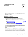
Initializing and Testing the System
■
Initializing the System
■ Setting
■
the Time and Date
Testing the System
■ Installing
the Control Unit’s Housing
7-1
7-3
7-3
7-20
Installation v
Contents
8
9
Installing Applications
Voice Messaging Systems and Touch-Tone
Receivers
8-2
Automated Document Delivery System
8-3
Call Accounting System
8-4
Call Accounting Terminal
8-7
Call Management System
8-9
CONVERSANT
8-12
Integrated Solution Ill
8-13
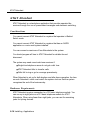
AT&T Attendant
8-16
MERLIN MAIL
8-17
MERLIN PFC
8-20
PassageWay Direct Connect Solution
8-22
System Programming and Maintenance (SPM)
8-24
Upgrading the System
the Control Unit Housing
9-2
Down the System
9-4
Upgrading the Control Unit
9-6
■ Removing
■ Powering
■
■ Modifying
■
the Processor for Key Mode
Completing the Upgrade
vi Installation
9-10
9-14
Contents
A
B
System Numbering Forms
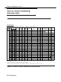
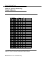
Form 2a, System Numbering: Extension Jacks
2
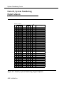
Form 2b, System Numbering: Digital Adjuncts
4
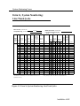
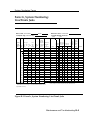
Form 2c, System Numbering: Line/Trunk Jacks
5
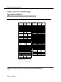
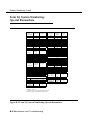
Form 2d, System Numbering: Special Renumbers
6
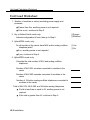
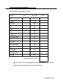
Unit Load Calculation Worksheet
Unit Load Worksheet
2
Index
Installation vii
Figures
2
Installing the Control Unit
AC Grounding Requirements
Measuring the AC Outlet Voltages
Central Office and AC Grounds
Installing 146A and 147A Protectors
Marking the Basic Carrier Screw Holes
Installing a Copper Shield in the Power Supply
Installing the Ferrite Cores
Installing an Auxiliary Power Unit
Connecting the Carriers
Installing the Processor into the Carrier
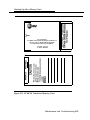
400EM Module Sample Dip Switch Settings for
Signaling Types 1C and 5
2-12. Line/Trunk and Telephone Jack Locations on
Each Module
2-13. Removing Modules from the Carrier
2-1.
2-2.
2-3.
2-4.
2-5.
2-6.
2-7.
2-8.
2-9.
2-10.
2-11.
3
2-7
2-9
2-11
2-15
2-18
2-22
2-24
2-26
2-28
2-31
2-37
2-39
2-42
Installing Telephones and Adjuncts
3-1.
3-2.
3-3.
3-4.
3-5.
3-6.
3-7.
3-8.
Multi-Function Module Packing List
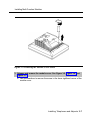
Removing the User Card Tray and Line Cable
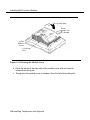
Releasing the Deskstand
Removing the Deskstand
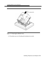
Releasing the Module Cover S c r e w
Releasing the Module Cover
Removing the Module Cover
Removing an MFM Module
viii Installation
3-3
3-4
3-5
3-6
3-7
3-8
3-9
3-10
Figures
Installing Telephones and Adjuncts, Continued
3-9.
3-10.
3-11.
3-12.
3-13.
3-14.
3-15.
3-16.
3-17.
3-18.
3-19.
3-20.
3-21.
3-22.
3-23.
3-24.
3-25.
3-26.
3-27.
3-28.
3-29.
3-30.
3-31.
3-32.
Installing an MFM Module
Setting and Adjusting the MFM Jumpers
Removing the Jack Guard
Placing the Module Cover into the Locating Slot
Lowering and Locking the Module Cover
Replacing and Tightening the Module Cover Srew
Replacing the Deskstand
Lowering the Deskstand and Locking into Place
Replacing the User Card Tray and Line Cable
Adjusting the Deskstand Height
Powering Up the Telephone after Installing the
MFM
Routing the Cord(s) Through the Cord Channel
Manual and One-Touch Headset Operation
Single-Zone Paging with PagePac Plus
Single-Zone Paging with Customer-Supplied
Amplifier
Single-Zone Paging with UPAM
Single-Zone Paging with Background Music and
Magic on Hold
Multizone Paging with Background Music, Magic
on Hold, and Bidirectional Paging (Talk-Back)
Installing the Supplemental Alert Adapter
Connecting One or More DSSs
Wiring for Auxiliary Power
Adjusting or Removing the Deskstand
Connecting the Line Cords
Removing the Extension Label
3-11
3-12
3-13
3-14
3-15
3-16
3-17
3-18
3-19
3-20
3-21
3-23
3-29
3-31
3-32
3-33
3-36
3-37
3-39
3-45
3-46
3-49
3-50
3-51
Installation ix
Figures
Installing Telephones and Adjuncts, Continued
Labeling the Extension
Removing the Handset Holder
Rotating the Handset Holder
Replacing the Extension Label
Mounting the Backplate
Routing the Cord Through the Backplate
Connecting Two Voice Pairs to a Telephone Using
a Bridging Adapter (BR-241-B1)
3-40. Removing the Connecting Block
3-33.
3-34.
3-35.
3-36.
3-37.
3-38.
3-39.
4
3-52
3-53
3-53
3-54
3-55
3-56
3-61
3-63
Connecting the Control Unit to the Network Interface
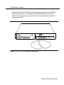
4–1. RJ21X Network Interface Connector
4–2. RJ21X Wiring Field Hardware
4-3. RJ21X Wiring Field Tools
4-4. Using the D-Impact Tool to Seat the Conductors
4–5. RJ11 and RJ14 Interfaces
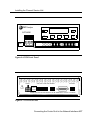
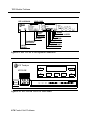
4-6. 3150 Front Panel
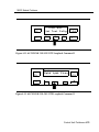
4-7. 3150 Back Panel
x Installation
4-5
4-6
4–7
4-8
4-10
4-17
4-17
Figures
5
Installing the PC, CAT, or Printer
5-1.
5-2.
5-3.
5-4.
5-5.
5-6.
5-7.
6
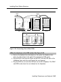
Connecting a PC Within 50 ft. (15.2 m)
Connecting a PC More Than 50 ft. (15.2 m) Away
Connecting a CAT and Printer on the Same AC
Outlet
Connecting a CAT and Printer on Different AC
Outlets: Control Unit Connections
Connecting a Printer Within 50 ft. (15.2 m)
Connecting a Printer More Than 50 ft. (15.2 m)
Away
Connecting the 2486 Adapter and the 2012D
Transformer
5-3
5-6
5-10
5-13
5-16
5-19
5-20
Connecting Data Equipment
6-1.
6-2.
6-3.
6-4.
6-5.
6-6.
Analog Voice and Modem Data Equipment
Configuration
Modem Data-Only Equipment Configuration
Modem Data and MLX Voice Equipment
Configuration
MLX Voice and 7500B Data Equipment
Configuration
7500B Data-Only Equipment Configuration
Video Conferencing Configuration
6-7
6-9
6-10
6-13
6-15
6-18
Installation xi
Figures
7
Initializing and Testing the System
7–1. Ground-Start Button
7–2. Installing the Control Unit Top Cover
7–3. Installing the Control Unit Front Cover
9
Upgrading the System
9–1. Removing the Control Unit Housing
9-2. Powering Down the System
9-3. Removing a Module from the Carrier
9–4. Replacing a Module in the Carrier
9–5. Removing the Processor Module Cover
9-6. Removing the Processor Module Circuit Board
9–7. Changing the Key Mode Switch Position to Closed
9-8. Installing the Control Unit Housing
A
7-18
7-21
7-22
9-3
9-5
9-7
9-9
9-11
9-12
9-13
9-17
System Numbering Forms
A–1.
A–2.
A-2.
A-4.
Form 2a, System Numbering: Extension Jacks
Form 2b, System Numbering: Digital Adjuncts
Form 2c, System Numbering: Line/Trunk Jacks
Form 2d, System Numbering: Special Renumbers
xii Installation
A-2
A-4
A-5
A-6
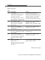
Tables
2
Installing the Control Unit
2-1. Environmental Requirements
2-2. AC Power Requirements
2–3. Heavy Lightning Protection
2-4. Setting the 400EM (Tie Trunk) Module DIP
Switches
2-5. Signaling Formats for the 400EM (Tie Trunk)
Module
3
2-2
2-8
2-14
2-35
2-36
Installing Telephones and Adjuncts
3-1. Unsupported Telephones and Adjuncts
3–2. Single-Line Telephones
3-3. Single-Line Telephones Supported by Release 3.0
and Later
4
3-40
3-41
3-42
Connecting the Control Unit to the Network Interface
4–1. Network Interfaces
4–2. Central Office Network Interface Codes
4-2
4-3
Installation xiii
Tables
5
Installing the PC, CAT, or Printer
5-1. AT&T 572 Printer Options.
5-2. AT&T 475/476 Printer DIP Switch Settings
5-3. AT&T CAT Printer DIP Switch Settings
6
Connecting Data Equipment
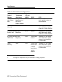
6–1. Data Station Configurations
6–2. 7500B Data Module Settings
8
5-22
5-24
5-25
6-2
6-20
Installing Applications
8-1. TTRs Required by VMS
8-2. MERLIN MAIL Ports Required
xiv Installation
8-3
8-17
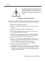
Safety
The exclamation point in an equilateral
triangle is intended to alert the user to the
presence of important operating and
maintenance (servicing) instructions in the
literature accompanying the product.
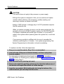
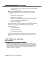
IMPORTANT SAFETY INSTRUCTIONS
When installing telephone equipment, always follow basic safety precautions
to reduce the risk of fire, electrical shock, and injury to persons, including:
Read and understand all instructions.
Follow all warnings and instructions marked on or packed with the
product.
Never install telephone wiring during a lightning storm.
Never install a telephone jack in a wet location unless the jack is
specifically designed for wet locations.
Never touch uninsulated telephone wires or terminals unless the
telephone wiring has been disconnected at the network interface.
Use caution when installing or modifying telephone lines.
Use only AT&T-manufactured MERLIN LEGEND Communications
System circuit modules, carrier assemblies, and power units in the
MERLIN LEGEND Communications System control unit.
Use only AT&T-recommended/approved MERLIN LEGEND
Communications System accessories.
If equipment connected to the analog extension modules (008, 408,
408 GS/LS) or to the MLX telephone modules (008 MLX, 408 GS/LSMLX) is to be used for in-range out-of-building (IROB) applications,
IROB protectors are required.
Installation xv
Safety
Do not install this product near water, for example, in a wet basement
.
location.
Do not overload wall outlets, as this can result in the risk of fire or
electrical shock.
The MERLIN LEGEND Communications System is equipped with a
3-wire grounding-type plug with a third (grounding) pin. This plug will
fit only into a grounding-type power outlet. This is a safety feature. If
you are unable to insert the plug into the outlet, contact an electrician
to replace the obsolete outlet. Do not defeat the safety purpose of the
grounding plug.
The MERLIN LEGEND Communications System requires a
supplementary ground.
Do not attach the power supply cord to building surfaces. Do not
allow anything to rest on the power cord. Do not locate this product
where the cord will be abused by persons walking on it.
Slots and openings in the module housings are provided for
ventilation. To protect this equipment from overheating, do not block
these openings.
Never push objects of any kind into this product through module
openings or expansion slots, as they may touch dangerous voltage
points or short out parts, which could result in a risk of fire or electrical
shock. Never spill liquid of any kind on this product.
Unplug the product from the wall outlet before cleaning. Use a damp
cloth for cleaning. Do not use cleaners or aerosol cleaners.
Auxiliary equipment includes answering machines, alerts, modems,
and fax machines. To connect one of these devices, you must first
have a Multi-Function Module (MFM).
Do not operate telephones if chemical gas leakage is suspected in
the area. Use telephones located in some other safe area to report the
trouble.
xvi
Installation
Safety
WARNING:
For your personal safety, DO NOT install an MFM yourself.
ONLY an authorized technician or dealer representative shall install,
set options, or repair an MFM.
To eliminate the risk of personal injury due to electrical shock, DO
NOT attempt to install or remove an MFM from your MLX telephone.
Opening or removing the module cover of your telephone may expose
you to dangerous voltages.
SAVE THESE INSTRUCTIONS
Installation xvii
Safety
xviii
Installation
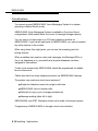
About This Book
The MERLIN LEGEND Communications System is an advanced digital
switching system that integrates voice and data communications features.
Voice features include traditional telephone features, such as Transfer and
Hold, and advanced features, such as Group Coverage and Park. Data
features allow both voice and data to be transmitted over the same system
wiring.
Intended Audience
This book is intended for qualified field technicians who install and upgrade
the system.
How to Use This Book
Qualified technicians can use this book as a guide to installation and
upgrading procedures. The technician is given specific steps for installing all
units of the control unit, telephones, adjuncts and data equipment.
Installation xix
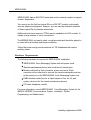
How to Use This Book
Refer to the following documentation for additional information:
Equipment and Operations Reference provides detailed information
on system hardware, telephones, and other equipment.
Feature Reference provides details on the features of the
communications system.
System Planning provides procedures and forms for planning a
system for installation.
System Programming gives procedural instructions for programming
system features.
Users’ guides and Operators’ Guides give procedural instructions for
programming and using telephone features.
“Related Documents,” later in this section, provides a complete list of system
documentation together with ordering information.
In the U.S.A. only, AT&T provides a toll-free customer Helpline (1 -800-6282888) 24 hours a day. Call the Helpline, or your AT&T representative, if you
need assistance when installing, programming, or using your system.
xx
Installation
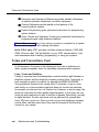
Terms and Conventions Used
Terms and Conventions Used
In this document, the terms in the following list are used in preference to
other, equally acceptable terms for describing communications systems.
Lines, Trunks and Facilities
Facility is a general term that designates a communications path between a
telephone system and the telephone company central office. Technically a
trunk connects a switch to a switch, for example the MERLIN LEGEND
Communications System to the central office. Technically, a line is a loopstart facility or a communications path that does not connect two switches
(for example, an intercom line or a Centrex line). However, in actual usage,
the terms line and trunk are often applied interchangeably. In this book, we
use line/trunk and lines/trunks to refer to facilities in general. Specifically, we
refer to digital facilities. We also use terms such as personal line, groundstart trunk, Direct Inward Dialing (DID) trunk, and so on. When you talk to
your local telephone company central office, ask them what terms they use
for the specific facilities they connect to your system.
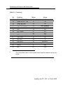
Some older terms have been replaced with newer terms. The following list
shows the old term on the left and the new term on the right:
trunk module
trunk jack
station
station jack
analog data station
digital data station
analog voice and analog data station
digital voice and analog data station
analog data only station
digital data only station
digital voice and digital data station
line/trunk module
line/trunk jack
extension
extension jack
modem data station
7500B data station
analog voice and modem data
station
MLX voice and modem data
station
modem data-only station
7500B data-only station
MLX voice and 7500B data
station
Installation xxi
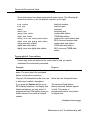
Product Safety Labels
Typographical Conventions
Certain type fonts and styles act as visual cues to help you rapidly
understand the information presented:
Example
It is very important that you follow
these steps. You must attach the
wristband before touching the
connection.
Purpose
Italics indicate emphasis.
The part of the headset that fits over
one or both ears is called a
headpiece.
Italics also set off special terms.
If you press the Feature button on an
MLX display telephone, the display
lists telephone features you can
select. A programmed Auto Dial
button gives you instant access to an
inside or outside number.
The names of fixed-feature, factoryimprinted buttons appear in bold. The
names of programmed buttons are
printed as regular text.
Choose Ext Prog from the display
screen.
Plain constant-width type indicates text
that appears on the telephone display
or personal computer (PC) screen.
To activate Call Waiting, dial *11.
Constant-width type in italics indicates
characters you dial at the telephone or
type at the PC.
Product Safety Labels
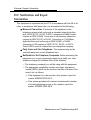
Throughout these documents, hazardous situations are indicated by an
exclamation point inside a triangle and the word caution or warning.
WARNING:
Warning indicates the presence of a hazard that could cause death or
severe personal injury if the hazard is not avoided.
xxii
Installation
Security
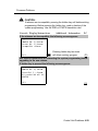
CAUTION:
Caution indicates the presence of a hazard that could cause minor
personal injury or property damage if the hazard is not avoided.
Security
Certain features of the system can be protected by passwords to prevent
unauthorized users from abusing the system. You should assign passwords
wherever you can and limit knowledge of such passwords to three or fewer
people.
Nondisplaying authorization codes and telephone numbers provide another
layer of security, For more information, see Appendix A, “Customer Support
Information” following Maintenance and Troubleshooting.
Installation xxiii
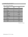
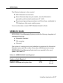
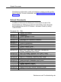
Related Documents
Related Documents
In addition to this book, the documents listed below are part of the
documentation set. Within the continental United States, these documents
can be ordered from the AT&T Customer Information Center by calling
1-800-432-6600.
Document No.
555-630-117
555-630-118
555-630-110
555-630-115
555-630-116
555-630-111
555-630-112
555-630-113
555-630-122
555-630-150
555-630-153
555-630-124
555-630-151
555-630-120
555-630-126
555-630-134
555-630-132
555-630-136
555-630-138
555-630-130
555-630-129
xxiv
I
Title
System Documents
Introduction
System Manager’s Guide
Feature Reference
Equipment and Operations Reference
,
Pocket Reference
System Programming
System Planning
System Planning Forms
Telephone User Support
TM
MLX-10D™, MLX-10DP™, MLX-28D™, and MLX-20L
Display Telephones User’s Guide
MLX-10D Display Telephone Tray Cards (5 cards)
MLX-28D and MLX-20L Telephone Tray Cards (5 cards)
MLX-10™ Nondisplay Telephone User’s Guide
MLX-10 Nondisplay Telephone Tray Cards (6 cards)
Analog Multiline Telephones User’s Guide
Single-Line Telephones User’s Guide
System Operator Support
MLX Direct-Line Consoles Operator’s Guide
Analog Direct-Line Consoles Operator’s Guide
MLX Queued Call Console Operator’s Guide
MDC 9000 and MDW 900 Telephones User’s Guide
Miscellaneous User Support
Calling Group Supervisor’s Guide
Data User’s Guide
Installation
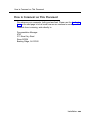
How to Comment on This Document
How to Comment on This Document
We welcome your comments, both good and bad. Please use the feedback
form on the next page to let us know how we can continue to serve you. If the
feedback form is missing, write directly to:
Documentation Manager
AT&T
211 Mount Airy Road
Room 2W226
Basking Ridge, NJ 07920
Installation xxv
How to Comment on This Document
xxvi
Installation
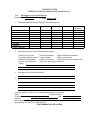
FEEDBACK FORM
MERLIN LEGEND Communications System Release 3.0
Title: Installation, Programming, & Maintenance
Order No.: 555-630-140 Date: August 1994
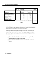
1.
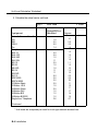
Please rate the effectiveness of this book in the following areas:
Excellent
Good
Fair
Poor
Not
Applicable
Ease of Use
Clarity
Completeness
Accuracy
Organization
Appearance
Examples
Illustrations
2.
Please check ways you feel we could improve this book:
❑ Improve the overview
❑ Improve the table of contents
❑ Improve the organization
❑ Include more illustrations
❑ Other
❑ Add more examples
❑ Add more detail
❑ Make it more concise
❑ Add more step-by-step
❑ Add troubleshooting information
❑ Make it less technical
❑ Add more/better quick reference aids
procedures
3.
What did you like most about this book?
4.
Feel free to write any comments below or on an attached sheet,
If we may contact you about your comments, please complete the following:
Telephone Number:
Name:
Date:
Company/Organization:
Address:
Send completed forms to: Documentation Manager, AT&T, 211 Mount Airy Road, Room 2W226,
Basking Ridge, NJ 07920. Fax: (908) 953-6912.
THIS FORM MAY BE PHOTOCOPIED
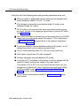
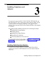
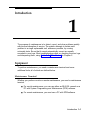
Introduction
1
Installation of the MERLIN LEGEND Communications System involves the
following:
,
■ Installing the control unit
■ Installing
the telephones
■ Connecting
■ Installing
system wiring
optional equipment
This chapter provides an overview of the installation process, which varies
from customer to customer.
Installation Sequence
The following is a list of the components that the system can include and
shows the order in which you should install them. When installing your
customer’s system, try to adhere to this order as much as possible:
1. Install the control unit (required).
2. Connect power accessories to the control unit (optional).
3. Install the telephones (required) and adjuncts (optional).
4. Connect the telephones to the control unit (required).
Introduction 1-1
System Forms
5.
Connect the control unit to the network interface (required).
6.
Connect the channel service unit (CSU) to the 100D module on the
control unit (required only with the 100D module).
7.
Connect the printer and PC to the control unit (optional).
8.
Connect data equipment to the control unit (optional).
9.
Initialize and test the system (required).
10. Install the control unit housing (required).
11. Install applications (optional).
A list of required tools and equipment is given before each installation
procedure.
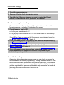
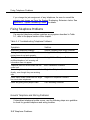
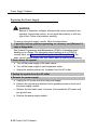
System Forms
Some of the installation procedures in this guide refer to system forms. These
forms indicate information that is specific to your customer’s system. The
forms you need should be included with the system programming disk or
memory card, which contains all of the programming specifically for your
customer’s system.
If you are upgrading an existing system and do not have the required forms
for your customer’s system, you can load System Programming and
Maintenance (SPM) and print out the required forms.
If you find that you do not have a completed set of system forms for your
customer’s system, contact your technical support organization or the
Customer Service Center (CSC). See the inside front cover for telephone
numbers.
The system forms that you need are specific for each system, and include
some or all of those described in the following sections.
1–2 Introduction
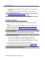
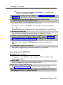
System Forms
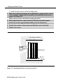
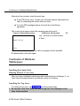
Installling the Control Unit
■
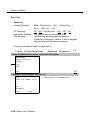
Form 1, System Planning. Some procedures in Chapter 2, “Installing
the Control Unit,” refer to the Control Unit Diagram, which is printed on
the reverse side of this form.
Form 3c, Incoming Trunks: Tie. If you install a 400EM module in the
control unit, use this form to determine the appropriate switch settings
prior to installation.
Installing Telephones (Required)
and Adjuncts (Optional)
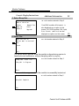
The following forms indicate the telephones and adjuncts that you must install:
■ Form
2a, System Numbering: Extension Jacks
■ Form
2b, System Numbering: Digital Adjuncts
■ Form
4b, Analog Multiline Telephone
■ Form
4d, MLX Telephone
■ Form
4e, MFM Adjunct: MLX Telephone
■ Form
4f, Tip/Ring Equipment
■ Form
5a, Direct-Line Console (DLC): Analog
■ Form
5b, Direct-Line Console (DLC): Digital
■ Form
5c, MFM Adjunct: DLC
■ Form
5d, Queued Call Console (QCC)
Connecting the Network Interface
The following forms indicate the trunks that you must connect to the control
unit. Information regarding the channel service unit (CSU) is included on
these forms.
■ Form
2c, System Numbering: Line/Trunk Jacks
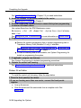
Introduction 1-3
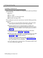
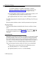
Programming the System
■ Form
3a, Incoming Trunks: Remote Access
■ Form
3b, Incoming Trunks: DS1 Connectivity (100D Module)
■ Form
3d, Incoming Trunks: DID
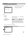
Connecting Data Equipment
The following forms indicate the data equipment you will need to set up data
stations.
■ Data
Form 1a, Modem Data Station
■ Data
Form 1b, 75006 Data Station
■ Data
Form 2, Data Hunt Groups
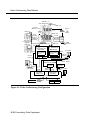
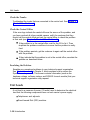
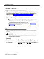
Programming the System
If you have a system programming disk created with SPM or a Translation
memory card, you do not need to program the system. Instead, you can use
the disk or memory card to restore the system; see Chapter 7, “Initializing and
Testing the System,” for instructions. If you did not receive a disk or a memory
card and it is your responsibility to program the system, see System
Programming for instructions.
Upgrading the System
If you are upgrading to Release 3.0 from Release 2.1, 2.0, 1.0, 1.1, or from the
®
MERLIN II Communications System, refer to Chapter 9, “Upgrading the
System,” then Chapter 7, “Initializing and Testing the System,” for upgrade
instructions.
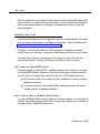
NOTE:
You cannot retain the programming from the MERLIN II Communications
System. You must first upgrade the hardware, then reprogram the system.
1-4 Introduction
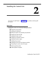
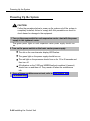
Installing the Control Unit
If you have not read Chapter 1, “Introduction,” do so before continuing with
this chapter.
Overview
Installing the control unit involves the following procedures:
Preparation requirements
Installing the backboard
Meeting the power and grounding requirements
Checking the total unit load
Installing the basic carrier
Installing any expansion carriers
Installing the power supply
Installing the processor
Installing the line/trunk and extension modules
Connecting the control unit to AC power
Powering up the system
Powering down the system
Installing the Control Unit 2-1
Overview
The following sections provide detailed instructions for these installation
procedures. Follow the procedures in the order in which they are presented.
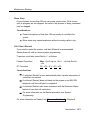
Environment
The control unit must be installed on a backboard. The placement of the
backboard, and the control unit on it, requires careful consideration. Make
sure you install the backboard in an area that meets all of the environmental
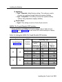
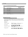
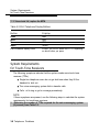
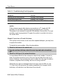
requirements listed in Table 2–1.
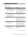
Table 2-1. Environmental Requirements
Operating
Temperatures
4 00-104°F (4°-400C )
Optimal temperature: 60°F(15.6°C)
Humidity
Airborne
Contamination
20%–80%
Ventilation
Allow at least 1 in. (2.54 cm) on the right and left sides of the control
unit and 12 in. (30.48 cm) minimum, above and below it, to prevent
overheating,
Do not expose the control unit to moisture, corrosive gases, dust,
chemicals, spray paint, or similar material.
Do not place the control unit near extreme heat sources (for example:
furnaces, heaters, attics, or direct sunlight).
Electrical Fields
Heat Dissipation
Do not expose the control unit to devices that generate electrical
currents causing interference (such as arc welders or motors).
Basic carrier: 500 Btu/hr
Basic carrier: with one expansion carrier 1000 Btu/hr
Basic carrier: with two expansion carriers 1500 Btu/hr
WARNING:
Do not install the control unit outdoors.
2-2 Installing the Control Unit
Overview
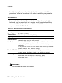
Electrical Noise/Radio-Frequency Interference
In most cases, electrical noise is introduced to the system through trunk or
telephone cables. However, electromagnetic fields near the control unit can
also cause noise in the system. Therefore, you should not place the control
unit and cable runs in areas where a high electromagnetic field strength
exists.
Radio transmitters (AM and FM), television stations, induction heaters, motors
(with commutators) of 0.25 horsepower (200 watts) or greater, and similar
equipment are leading causes of radio-frequency interference (RFI). Small
tools with universal motors are generally not a problem when they operate on
separate power lines. Motors without commutators generally do not cause
interference.
Field strengths below 1.0 volt per meter are unlikely to cause interference. To
estimate the field strength produced by radio transmitters, divide the square
root ( ✔ ) of the emitted power, in kilowatts, ( : ) by the distance from the antenna
in kilometers which equals (=) the field strength in volts per meter.
Example: {49,000 kw = 7,000 : 10 km (6.2 miles) = 0.7 volts per meter
This yields the approximate field strength in volts per meter and is relatively
accurate for distances greater than about half a wavelength (492 ft., or 150 m,
for a frequency of 1000 Hz). If the result exceeds 1.0 volt per meter, you may
have to install shielded cables and or Z200A filters. See Appendix A,
“Customer Support Information,” following Maintenance and Troubleshooting,
for FCC Part 15 radio frequency regulations.
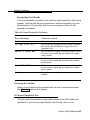
Control Unit Requirements
■
Dimensions
— Basic carrier: 14 in. wide by 23 in. high by 12 in. deep
— Basic carrier and one expansion carrier: 25 in. wide by 23 in. high
by 12 in. deep
Installing the Control Unit 2-3
Overview
— Basic carrier and two expansion carriers: 37 in. wide by 23 in. high
by 12 in. deep
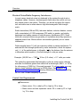
■
Location
— Within 5 ft. (152 cm) of an AC power outlet that is not switchcontrolled
— Within 25 ft. (762 cm) of the network interface, or use an OffPremises Range Extender (OPRE)
— Within 1000 cable ft. (305 m) of telephones, or use an OPRE (for
basic telephones)
CAUTION:
The AC outlet for the control unit cannot be switch-controlled, Plugging
the control unit into such an outlet invites accidental disconnection of
the system.
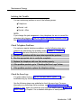
Hardware Preassemble Process
If an installation is to be preassembled, wired, programmed, and tested on
the new lightweight plastic backboard, see “Installing the Backboard.”
Backboard Requirements
The backboard should be wide enough to accommodate the carrier and up to
two additional carriers, assuming that system growth is anticipated. There
should be enough room on each side of the control unit for the necessary
wiring fields,
To accommodate the maximum control unit size, make sure the backboard
meets the following requirements:
■
Material
— ¾-inch plywood
— Check with the local building code enforcement agency to see
whether fire-retardant material is required.
2-4 Installing the Control Unit
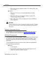
AC Power and Grounding
— Make sure that the material meets local building codes.
■ Dimensions
®
— With Systimax wiring: 7 ft. wide by 4 ft. high
— Without Systimax wiring: 6 ft. wide by 3 ft. high
Installing the Backboard
When you are certain that the backboard meets the requirements indicated
above, or is the new lightweight plastic material backboard with
preassembled equipment in place, attach the backboard to the wall.
Use the following mounting hardware:
■ For
a wood mounting surface, use wood screws.
■ For
brick, cinderblock, or concrete, use masonry anchors.
■ For
plaster or plasterboard, use toggle bolts.
■ For
sheet metal, use sheet-metal screws and attach them to the
structural members.
NOTE:
The mounting hardware should resist a combined pullout force of at least 650
pounds (295 kilograms).
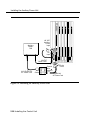
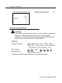
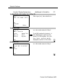
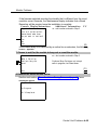
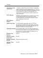
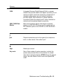
AC Power and Grounding
Proper power and grounding are essential for the system to run correctly and
safely.
CAUTION:
If any of the following requirements are not met, the customer must
contact a licensed electrician. Do not install the system until all
requirements are met.
Installing the Control Unit 2-5
AC Power and Grounding
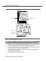
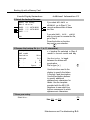
Verify that all of the following power and grounding requirements are met:
The load center of appropriate current rating must be equipped with
circuit breaker(s) labeled 120 VAC, 15 amps.
■
Each breaker must protect one dedicated quad AC outlet or two
dedicated duplex AC outlets.
■
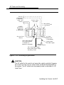
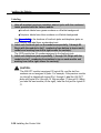
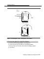
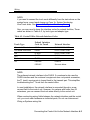
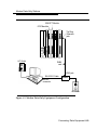
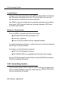
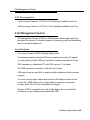
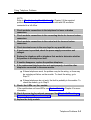
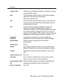
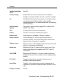
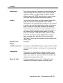
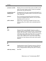
All AC outlets must connect to the same load center and the ground
wire must connect to the single-point ground bar on the first AC outlet
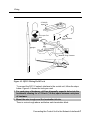
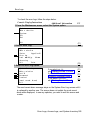
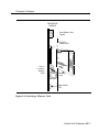
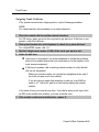
(see Figure 2-1).
One outlet must have an attached ground bar connected by a #6 AWG
copper wire to an approved ground (see page 2-12 for a description
of approved grounds). This ground bar is the system’s single-point
ground (see Figure 2-1 ).
To prevent someone from accidentally shutting off the power, do not
connect the control unit to a switch-controlled outlet.
The AC outlet should be within 5 ft. (152 cm) of the control unit.
Each carrier requires one AC outlet receptacle.
Auxiliary equipment requires additional AC outlets.
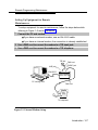
If a printer or PC is installed on the system, it must be plugged into the
same AC branch as the power supply of the basic carrier.
If the printer or PC is 50 ft. (15 m) or more from the control unit, or is
plugged into a different AC circuit, Asynchronous Data Units (ADUs)
must be installed as well. Chapter 5, “Installing the PC, CAT, or
Printer,” includes complete installation instructions.
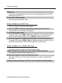
The AC power requirements indicated in “AC Outlet Tests,” below,
must be met.
2-6 Installing the Control Unit
AC Power and Grounding
From AC
Load Center
(2 separately
fused 15A
circuits)
Ground Wire
#14 AWG
4" Box (RACO 230
or equivalent)
HUBBELL
Receptacles
(5262 15A
or equivalent)
4“ Cover
(RACO 807
or equivalent)
Single-Point
Ground
Ground Bar Mounted
on a 4“ Box (Square
“D” PK9GTA or
approved equivalent)
Ground Wire
#6 AWG Copper
Approved
Building Ground
#12 or #14 AWG Copper
Wire to Each Power Supply
Grounding Screw
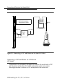
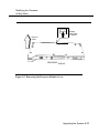
Figure 2-1. AC Grounding Requirements
CAUTION:
The AC outlet for the control unit cannot be switch-controlled, Hugging
the control unit into such an outlet invites accidental disconnection of
the system. The AC outlet must be properly wired as described in “AC
Outlet Tests. ”
Installing the Control Unit 2-7
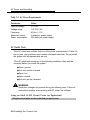
AC Power and Grounding
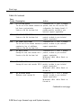
Table 2-2. AC Power Requirements
Parameter
Value
Nominal voltage
Voltage range
Frequency
Maximum current
Power consumption
117VAC
110-125 V AC
60 Hz +/– 5%
3 amps per power supply
225 watts per power supply
AC Outlet Tests
If the AC outlet tests indicate that any of the power requirements in Table 2-2
are not met, your customer must contact a licensed electrician. Do not install
the system until all requirements are met.
If the AC outlet tests reveal any of the following conditions, they must be
corrected before you install the system:
■
Open ground
■ Hot
■
and neutral reversed
Open hot
■ Open
■ Hot
neutral
and ground reversed
WARNING:
Hazardous voltages are present during the following tests. Follow all
instructions carefully when working with AC power line voltages.
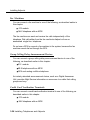
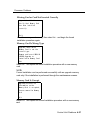
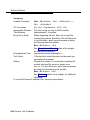
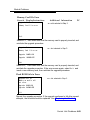
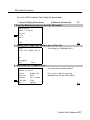
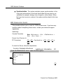
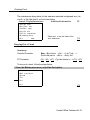
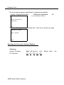
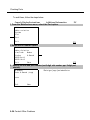
Using an Ideal 61-035 Circuit Tester (or Equivalent)
1 Plug the circuit tester into the outlet that you want to test.
2-8 Installing the Control Unit
AC Power and Grounding
If the circuit is properly grounded, the ye low and white lights on the tester
turn on.
2 Unplug the circuit tester.
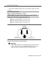
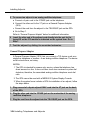
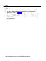
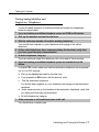
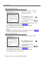
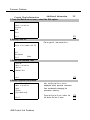
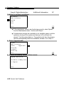
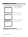
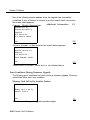
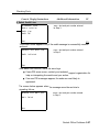
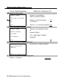
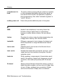
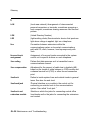
Using a Volt-Ohm Milliammeter (VOM)
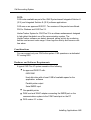
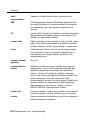
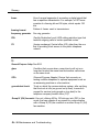
1 Set the VOM to the lowest scale on which you can read 130 V AC.
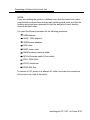
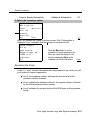
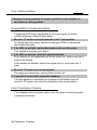
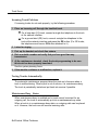
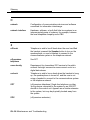
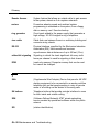
2 Measure the AC outlet voltages. See Figure 2-2.
■ Phase
to ground should be 110 to 125 V AC.
■ Neutral to ground should be less than 1 V AC.
■ Phase
to neutral should be 110 to 125 V AC.
110-125
/ Volts AC\
Neutral
Phase
(HOT)
Ground
Less than
1.0 Volt AC
110-125
Volts AC
Figure 2-2. Measuring the AC Outlet Voltages
WARNING:
If the voltage readings do not measure the values required, the AC
outlet is improperly wired- do not install the system. Advise the
customer to have a licensed electrician correct the problem.
Installing the Control Unit 2-9
AC Power and Grounding
Grounding Requirements
Proper grounding of the installation site safeguards the system by protecting it
from the following:
■ Lightning
■ Power
■ Power
surges
crosses on central office trunks
■ Electrostatic
discharge (ESD)
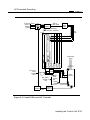
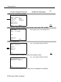
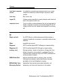
When installing the control unit, make sure you meet the following grounding
requirements:
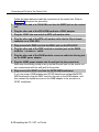
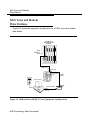
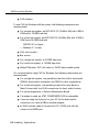
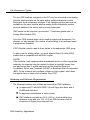
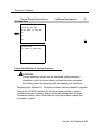
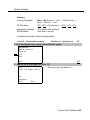
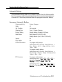
The control unit, the central office trunk protector, and the AC power
service panel should be as close to each other as possible.
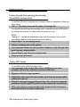
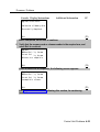
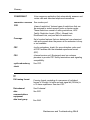
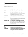
Because equipment can be located throughout a building, the
National Electrical Code requires that the ground point for the central
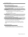
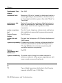
office trunk protector be bonded to the AC power ground as shown in
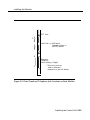
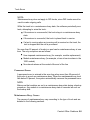
Figure 2-3.
The AC outlet and the single-point ground bar must be properly
grounded as shown in Figure 2-1 and Figure 2-3.
Each power supply in the control unit must be connected to the singlepoint ground bar by a #12 AWG or a #14 AWG solid copper wire.
Figures 2–1 and 2–3 show this connection.
This wire run should be as short as possible, preferably within 5 ft.
(152 cm), not to exceed 10 ft. (305 cm), See “Approved Grounds,”
later in this chapter, for more information.
The AC outlet must be connected to the 147A protector with#12 AWG
or a #14 AWG solid copper wire.
2-10 Installing the Control Unit
AC Power and Grounding
To Central
Office or
Serving
Facility
Lines
CO
Line
Protector
Network
Interface
DIW or
25-Pair Cable
CO
Wiring
Field
Coupled Bonding
Conductor (optional)
(Power)
(Supply
)
D2R
Cords
I
Commercial
Power
A C
Plug Outlet
#12 or #14
AWG
Ground
Wire
#6 AWG
Ground
Wire
Earth
Ground
Bond
Wire
Single Point
Ground
Bar
Shield
Ground
B
Power
Service
W
GND (Green)
Power
Ground
Rod
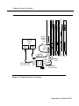
Figure 2-3. Central Office and AC Grounds
Installing the Control Unit 2-11
AC Power and Grounding
WARNING:
Improper ground can cause equipment failures, service outages, and
electrical shock. Verify that the AC power uses an approved ground for
its primary ground, that all voltage-limiting devices are grounded to an
approved ground, and that the ground is one of the approved grounds
listed below.
Approved Grounds
Approved grounds are listed below, in order of preference:
■
Building Steel. The most preferred ground.
■
Acceptable Water Pipe. Must be a metal, not plastic or vinyl,
underground water pipe at least ½ in. (1.27 cm) in diameter, and in
direct contact with the earth for at least 10 ft. (3 m).
It must be electrically continuous so that the protector ground is
uninterrupted. (Check for insulated joints, plastic pipe, and plastic
water meters that might interrupt electrical continuity. )
A metallic underground water pipe must be supplemented by the
metal frame of the building, a concrete-encased ground, or a ground
ring. If these grounds are not available, the water pipe ground can be
supplemented by one of the following types of grounds:
— Other local metal underground systems or structures, such as
tanks and piping systems, but not gas pipes
— Rod and pipe electrodes, a 5/8-in. (1.58-cm) solid rod or ¼-in.
(0.63-cm) conduit or pipe electrode driven to a minimum depth of 8
ft. (244 cm)
— Plate electrode, a minimum of 2 square ft. (61 square cm) of
metallic surface exposed to the exterior soil
2-12 Installing the Control Unit
AC Power and Grounding
■
Concrete-Encased Ground. Must be an electrode, consisting of one
of the following:
At least 20 ft. (6.1 m) of one or more steel reinforcing rods, each at
least ½ in. (1.27 cm) in diameter
20 ft. (6.1 m) of bare copper conductor not smaller than #4 AWG,
encased in 2 in, (5 cm) of concrete
This electrode must be located within and near the bottom of a
concrete foundation or footing that is in direct contact with the
earth.
Ground ring, consisting of at least 20 ft. (6.1 m) of bare copper
conductor (not smaller than #2 AWG) encircling the building. The
ground ring must be in direct contact with the earth and buried at
least 2.5 ft. (77 cm) below the earth’s surface.
WARNING:
Do not use a metal underground gas piping system—this is a safety
risk.
Central Office Trunk Protection
The telephone company is responsible for providing the following protection
of central office (co) trunks at the entrance to the site:
■
Carbon blocks or gas discharge tubes connected to an approved
ground
■
Adequate bonding of the central office trunk protector ground and the
power company ground
CAUTION:
Check these requirements with a simple, visual inspection. If you cannot
verify that the central office grounding requirements are met, contact the
central office. Do not connect the control unit to the central office trunks
until you are certain that these requirements are met.
Installing the Control Unit 2-13
AC Power and Grounding
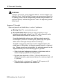
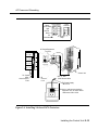
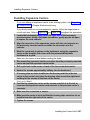
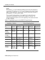
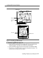
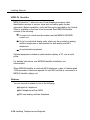
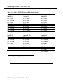
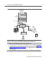
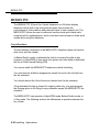
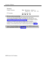
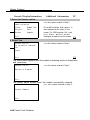
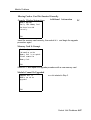
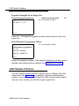
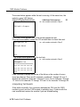
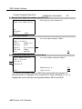
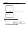
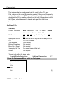
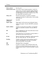
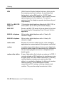
Heavy Lightning Protection
For most surges, adequate protection is provided by meeting the previously
listed requirements. Additional protection is required when the customer is
located in a heavy lightning area.
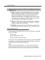
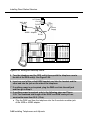
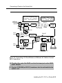
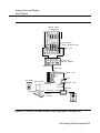
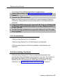
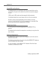
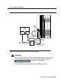
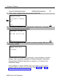
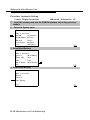
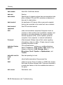
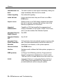
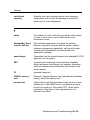
Connect a 147A protector to the system to limit surges from the AC lines and
up to four CO trunks.
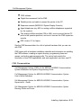
For systems with more than four CO trunks, do the following:
■
Connect a 146A protector to the 147A protector, providing protection
for an additional four trunks.
■
Connect up to three (maximum) 146A protectors to a 147A protector,
allowing a maximum of 16 trunks on one 147A protector.
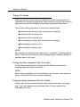
■
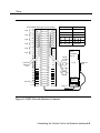
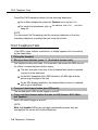
For more than 16 trunks, add another 147A protector and continue
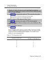
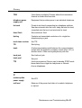
adding 146A protectors as needed. See Table 2–3 for various
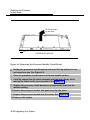
configurations and Figure 2–4 for a typical 147A protector installation.
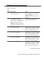
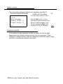
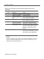
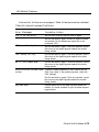
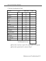
Table 2-3. Heavy Lightning Protection
Number of CO Trunks
1-4
5-8
9-12
13-16
17-20
21-24
Required Protectors
147A
147A and a 146A
147A and two 146As
147A and three 146As
Second 147A
Second 147A and one 146A
NOTES:
1. When you use the second 147A, you can connect the 146As in any
combination, up to a maximum of three 146As per 147A.
2. For detailed installation instructions, see the documentation packaged with
the protectors.
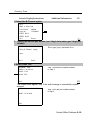
2-14 Installing the Control Unit
AC Power and Grounding
147A Protector
Status
Indicator
Light
146A
Protector
Ground
Strap
AC
Connection
Ground
Strap
AC Surge/Suppressor
Protector
CONTROL UNIT
TEL CO LINE
CONTROL UNIT
TEL CO LINE
CONTROL UNIT
TEL CO LINE
AC
Outlet
CONTROL UNIT
\ TEL CO LINE
Control Unit
To Central
Office
Cross-Connect
Field
TO
Control
Unit
#12 or #14
AWG Ground Wire
To Power Supply
Module
Connect telecommunications
equipment only to these outlets.
Maximum load 12.5A
Figure 2-4. Installing 146A and 147A Protectors
Installing the Control Unit 2-15
Unit Loads
Unit Loads
A unit load is a measure of power (1.9 watts) that you use to determine the
electrical load that the components listed below place on the control unit’s
power supply.
■ Telephones
■ 800
and adjuncts
DID modules
Only the telephones and adjuncts that connect to the analog and digital
extension jacks (ports) on the control unit require unil load calculation, When
calculating unit load, do not include any equipment with its own power supply.
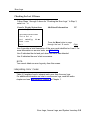
Checking Unit Loads
In the event of maintenance or equipment changes, recalculate the unit loads
for each carrier where there is a new configuration. Use the worksheet in
Appendix B, “Unit Load Calculation Worksheet.”
As a general rule, if you can distribute the 800 DID modules and telephone
modules equally across the carriers, you prevent unnecessary drain on any
one carrier. However, the rule varies depending on the system’s mode. The
next two sections provide the rules for calculating unit loads in various modes.
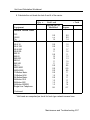
Unit Loads for Hybrid/PBX Mode
The power supply (model 391A1) generally supports six modules of any type
in Hybrid/PBX mode, without requiring an auxiliary power unit. If the following
conditions are true, however, the unit loads on a carrier can exceed the
54-unit maximum and, therefore, require auxiliary power:
All six carrier slots are occupied by MLX telephone or analog multiline
telephone modules.
The carrier has a total of more than 45 MLX-20L telephones or
34-button analog multiline telephones installed.
2-16 Installing the Control Unit
Installing the Basic Carrier
Unit Loads for Key or Behind Switch Mode
In a Key or Behind Switch system with four or fewer modules, no calculation is
needed. The power supply (model 391A1) generally supports four modules of
any type.
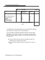
Auxiliary Power Units
The power supply provides 54 unit loads to each carrier. If the unit load
requirement for a carrier exceeds 54, an auxiliary power unit is needed to
allow that carrier to support up to an additional 27 unit loads.
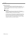
CAUTION:
Running the system with more than 54 unit loads per carrier may not
appear to do harm. However, this can cause the system to malfunction,
creating “NO Trouble Found” situations, such as malfunctioning LEDs on
multiline telephones or power unit failure.
Any extension that is connected to the modules in the last two slots receives
power from the auxiliary power unit instead of from the power supply.
If an auxiliary power unit is required, refer to “Installing the Auxiliary Power
Unit,” later in this chapter, for instructions.
Installing the Basic Carrier
Continue with this procedure only if you have met all of the requirements
discussed earlier in this chapter.
NOTE:
When you mount the basic carrier onto the backboard, leave 29 in. (73.66 cm)
of backboard to the right. This allows you to easily install and remove the
control unit cover, and also allows enough room for system expansion to the
right for the total length of up to three carriers.
Installing the Control Unit 2-17
Installing the Basic Carrier
1
2
To install the basic carrier, follow the steps below:
Mark the screw-hole locations on the backboard, using the basic carrier
or the template supplied with the plastic preassembled backboard as a
guide. See Figure 2-5.
Make sure the carrier is level before marking the holes.
Drill a pilot hole in the center of each of the four screw-hole marks.
3 Anchor the screws approximately halfway into the backboard.
4
Position the carrier on the screws and slide the carrier to the left.
5 Tighten the screws.
Mounting Surface
Mounting ‘\ ‘
Screw
\
\
Backboard
Basic
Carrier
Figure 2-5. Marking the Basic Carrier Screw Holes
2-18 Installing the Control Unit
Installing the Power Supply
Installing the Power Supply
WARNING:
Do not attach any cab/es or power cords to the power supply until it is
installed in the carrier.
Do not power up the control unit until all of the modules and power
equipment are installed. Once they are installed, refer to “Powering Up
the System, ” later in this chapter. Failure to comply with this procedure
can result in shock hazard and or damage to the equipment.
If you are upgrading an older system and a ring generator is specified in
the system forms (Control Unit Diagram), install it in the power supply
before putting the power supply in the carrier. The procedure is detailed
in Maintenance and Troubleshooting.
For expansion carriers only, a copper shield must be installed on the
power supply before installing it in the carrier. The procedure is
explained in “Installing a Copper Shield,” later in this chapter.
Before touching leads, connectors, pins, and other components, use a
properly grounded wrist strap, to prevent damage from electrostatic
discharge (ESD).
Remove the protective cover from the gold-finger connector (on the
back of the power supply) before inserting it into the carrier.
Installing the power supply can involve as many as four procedures,
depending on the system configuration. The procedures are:
■ Turning
off all power to the control unit
■ Installing
a copper shield
■ Installing
the ferrite cores
Installing the Control Unit 2-19
Installing the Power Supply
NOTE:
It is not necessary to install ring generators in a new system with new012
(apparatus code 517G13 or later letter) modules or new 008 (apparatus
code 5171328 or later letter). If you are upgrading or using older modules,
see Maintenance and Troubleshooting.
Turning Off the Power
1 Turn off each power supply.
2 Disconnect all power cords and auxiliary units.
Installing a Copper Shield
The added power supply in each expansion carrier can cause excessive
noise in the module occupying the next slot, To eliminate this noise, a copper
foil shield is installed over the power supply. These shields and their labels
are packaged in the power unit shielding kit included with the expansion
carrier.
To install a copper shield, follow the steps below. Refer to Figure 2-6
throughout the procedure.
1 Make sure all power is off.
2
Place the power supply on a flat surface with the right side up (as viewed
from the front edge).
3 Wipe the module free of any dust or dirt.
4 Peel the backing paper from the smaller copper-foil shield to expose the
adhesive.
Check the positioning of the foil shields before sticking them to the side of the
module. Once in place, the foil is difficult to remove.
5 Position the foil on the upper part of the module and work out any air
bubbles as you press the foil firmly in place.
2-20 Installing the Control Unit
Installing the Power Supply
..
6 Peel the backing paper from the larger copper-foil shield to expose its
adhesive.
7 Position the foil on the lower part of the module.
a The shields must meet.
b They should not overlap or have any space between them.
Installing the Control Unit 2-21
Installing the Power Supply
Upper Copper
Foil Shield
Lower Copper
Foil Shield
Power Unit
Information
Label
UL Label
or
CSA Label
Figure 2-6. Installing a Copper Shield in the Power Supply
8 Tuck the foil shield tightly along the ledge (or crease) of the housing and
work out any air bubbles as you press the foil firmly in place.
9
With the copper-foil shield in place, put the power unit information label
on the lower piece of foil.
10 Attach the UL or CSA label on the power supply below the copper-foil
shield.
2-22 Installing the Control Unit
Installing the Power Supply
Installing the Power Supply Module
in the Carrier
1 Lower the power supply module hook onto the rod on top of the carrier.
2 Make sure the connector on the module mates properly with the
connector on the carrier.
3 Push the module into the carrier until it locks into place.
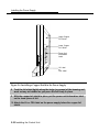
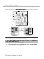
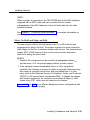
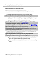
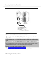
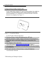
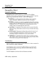
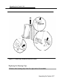
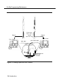
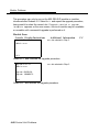
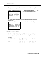
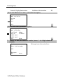
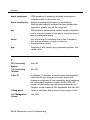
Installing the Ferrite Cores
At this point, the power supply should have been installed in the carrier, but
there should be no cables or power cords attached to the power supply
module.
NOTE:
If you are upgrading a system, unplug the AC power cord and remove the
ground wire attached to the grounding screw on the front of the power supply.
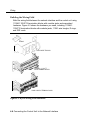
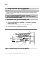
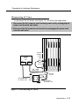
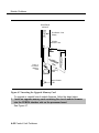
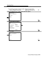
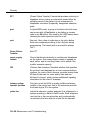
Follow these steps to install the ferrite cores:
1 Feed the AC power and ground wire through the wire manager (refer to
Figure 2-7).
2
Open the ferrite cores by unsnapping the plastic case.
3 Attach a ferrite core around the AC power cord and the ground wire by
snapping the plastic case shut.
4 Attach the second ferrite core adjacent to the first ferrite core by
repeating Steps 2 and 3.
5 Slide the ferrite cores between the wire manager and the power supply
module (refer to Figure 2-7).
6 Attach the ground wire to the grounding screw on the power supply
module.
7
Check that the other end of the ground wire is connected to the terminals
of the single-point ground baron the AC outlet box.
Installing the Control Unit 2-23
Installing the Power Supply
CAUTION:
Do not connect the power cord until the entire control unit is assembled.
POWER SUPPLY MODULE
AC Power Cord
Ground Wire
Attach
Ferrite Cores
(Open Position)
On/Off Power Indicator (Green LED)
-48 VDC Auxiliary Power Input Jack
On/Off Switch
AC Power Input
Grounding Screw
Wire Manager
Feed AC Power Cord and
Ground Wire through
Wire Manager
Figure 2-7. Installing the Ferrite Cores
2-24 Installing the Control Unit
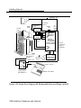
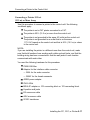
Installing the Auxiliary Power Unit
Installing the Auxiliary Power Unit
The Control Unit Diagram on the back of Form 1, System Planning, indicates
whether an auxiliary power unit is required for the carrier that you are
installing.
NOTE:
Use the 9024 auxiliary power unit for new installations. You can continue to
use a previously installed 335A auxiliary power unit, as long as no new
telephones or modules are added to the carrier.
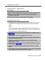
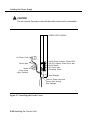
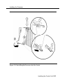
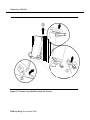
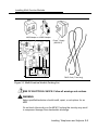
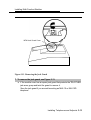
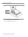
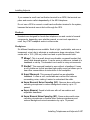
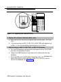
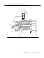
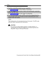
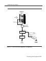
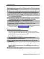
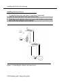
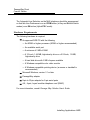
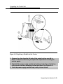
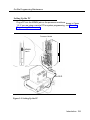
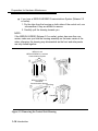
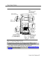
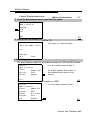
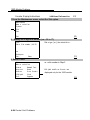
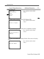
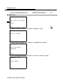
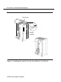
To install an auxiliary power unit, follow the steps below. Refer to Figure 2-8
throughout this procedure.
1 Turn off the switch on the power supply.
2 Mount the auxiliary power unit on a surface (preferably the backboard)
within 2 ft. (61 cm) of the control unit.
3 Plug the power unit line cord into the AUX POWER INPUT jack on the
power supply.
4 Plug the other end of the line cord into the AUX POWER jack on the
auxiliary power unit.
CAUTION:
Do not plug the power supply or the auxiliary power unit into the AC
outlet until you are ready to turn on the system, as described in
“Powering Up the System” later in this chapter.
If the system is backed up by an Uninterruptible Power Supply (UPS),
connect the auxiliary power to the UPS.
Do not attach the power cord(s) to any building surfaces.
Use only the power unit line cord supplied with the auxiliary power unit.
An incorrect cord will damage the power supply and may damage
modules.
Installing the Control Unit 2-25
Installing the Auxiliary Power Unit
-48 VDC
Auxiliary
Power
lnput
Auxiliary
Power
Unit
AC
Input
-48 VDC
Power Cord
Ground
Wire
AUX Power Unit
AC Power Cord
Ferrite
Cores
AC
Outlet
Figure 2-8. Installing an Auxiliary Power Unit
2-26 Installing the Control Unit
Control Unit
AC Power Cord
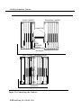
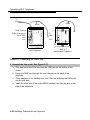
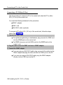
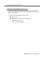
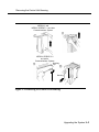
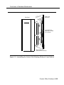
Installing Expansion Carriers
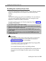
Installing Expansion Carriers
If you are adding an expansion carrier to an existing system, see “Upgrading
the Control Unit” in Chapter 9 before continuing.
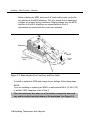
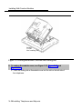
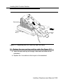
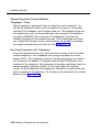
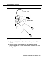
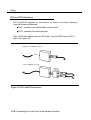
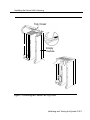
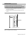
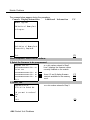
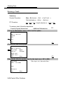
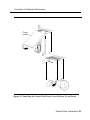
If you are to install one or more expansion carriers, follow the steps below to
mount each one. Refer to Figure 2–9 and Figure 2–5 throughout the procedure.
1
Locate the breakaway plastic tab on the right side of the previously
mounted carrier, Using a flat-blade screwdriver, gently pry the tab open
to expose the card extender.
2 Align the connector of the expansion carrier with the card extender on
the previously mounted carrier and slide the connector onto the
extender.
3
4
5
Mark the screw-hole locations on the backboard, using the expansion
carrier or the template that comes with the preassembled plastic
backboard as a guide.
Make sure the carrier is level before marking the holes.
Disconnect the expansion carrier connector from the previously mounted
carrier and put the expansion carrier aside.
Drill a pilot hole in the center of each of the four screw-hole marks.
6 Anchor the screws approximately halfway into the backboard.
7
If housing clips are to be installed on the housing and this is the last
carrier in the control unit, place the housing clips around the right-hand
molding for the screws on the back of the carrier.
If not, go to Step 8.
8 Position the expansion carrier on the screws and slide it to the left, to
reconnect the expansion carrier card extender to the previous carrier’s
connector.
9
Make sure the connection is secure.
10 Make sure the carrier is level and that the housing clips extend as far as
possible from the right side of the carrier.
11 Tighten the screws.
Installing the Control Unit 2-27
Installing Expansion Carriers
EXPANSION CARRIER
BASIC CARRIER
CONNECTOR
CARD
EXTENDER
(under the
breakaway tab)
BACKBOARD
BASIC CARRIER
EXPANSION CARRIER
BACKBOARD
Figure 2-9. Connecting the Carriers
2-28 Installing the Control Unit
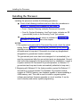
Installing the Processor
Installing the Processor
Installing the processor includes the following procedures:
■
If both of the following conditions are true, follow the procedures in
Chapter 9, “Modifying the Processor for Key Mode.”
— Form 1, System Planning, indicates Permanent Key mode.
— Form 2c, System Numbering: Line/Trunk Jacks, indicates no GS
(ground-start) trunks in the Incoming Trunk Type column.
■
Insert the processor into the carrier as indicated in "Installing the
Processor in the Carrier,” later in this chapter.
NOTES:
1. If the system is programmed for Permanent Key mode, check the switch
setting. Refer to Chapter 9, “Modifying the Processor for Key Mode” for
detailed procedures. If the switch is set to Permanent Key-only operation,
all trunks revert to loop-start. If the switch is not set, any programmed
designation for ground-start trunks is retained.
The ground-start pool never has trunks assigned to it automatically, but
must be programmed after the ground-start ports are designated. Groundstart trunks are assigned to the ground-start pool on initialization, except in
a system switched for Permanent Key mode operation. (In Release 1.0,
ground-start and loop-start trunks automatically defaulted to loop-start.)
2. Beginning with Release 3.0, the feature module required for Release 2.1
and earlier is no longer needed. The Release 3.0 processor module
contains a PCMCIA memory card interface capable of accommodating a
4-MB memory card. This card is used to install or upgrade system
software and perform firmware upgrades on circuit modules. It can be
used to backup and restore system programming.
Installing the Control Unit 2-29
Installing the Processor
CAUTION:
Before touching leads, connectors, pins, and other components when
handling the circuit board, use a properly grounded wrist strap to
prevent damage from electrostatic discharge (ESD).
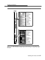
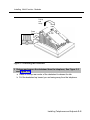
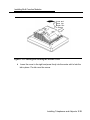
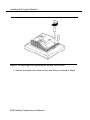
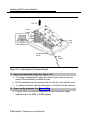
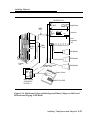
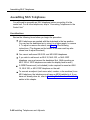
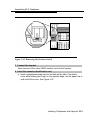
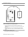
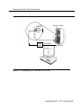
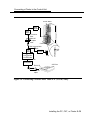
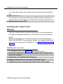
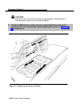
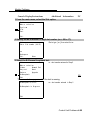
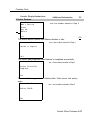
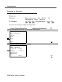
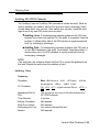
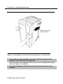
Installing the Processor in the Carrier
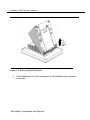
1
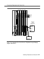
To install the processor in the carrier, follow the steps below, Refer to Figure
2-10.
Remove the protective cover from the gold-finger connector on the back
of the processor.
2
Lower the hook on top of the processor module onto the rod on top of
the carrier in Slot 0, the first slot next to the power supply.
3
Make sure that the connector on the module mates properly with the
connector on the carrier as you swing the processor down into place.
CAUTION:
To avoid damage, do not force the module. If the module does not insert
easily, press the bottom rear locking tab, remove the module, and
inspect the module and carrier for damage or obstruction. The bottomrear locking tab is shown in Figure 2–10. This tab is used on all
modules.
If there is no damage and no obstruction, reinsert the module.
A damaged carrier or module must be replaced.
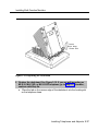
4
Push firmly until the processor snaps into place.
The processor should be securely attached to the carrier and locked in place
by the locking tab on the bottom rear of the processor.
2-30 Installing the Control Unit
Installing the Processor
Figure 2-10. Installing the Processor into the Carrier
Installing the Control Unit 2-31
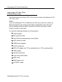
Installing the Modules
Installing the Modules
CAUTION:
Use a properly grounded wrist strap to prevent damage from
electrostatic discharge (ESD) when installing the modules, and avoid
touching leads, connectors pins, and other components.
Guidelines
Follow these guidelines when you install modules, as indicated on the Control
Unit Diagram of Form 1, System Planning:
Do not leave empty slots between modules. The system ignores
modules installed beyond any empty slot.
If a phantom module (a programmed empty slot) is indicated on the
Control Unit Diagram, make sure the slot remains empty and do not
install any modules to the right of it. The system ignores any modules
installed to the right of a programmed empty slot.
Make sure you install each module in its assigned slot. If you install a
module in the wrong slot, the system will not function properly,
Be sure to place all 012 modules and all 008 OPT modules without
built-in ring generators in carriers with modules that have ring
generators so that the modules without ring generators can be
supported.
Once you have installed the power supply and the processor in the
basic carrier, use the remaining slots for the modules as follows:
— Basic carrier: slots 1 through 5
— First expansion carrier: slots 6 through 11
— Second expansion carrier: slots 12 through 17
2-32 Installing the Control Unit
Installing the Modules
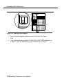
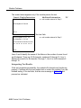
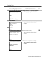
Installing Modules
To install modules starting from slot 1 (the first open slot next to the
processor), follow the steps below:
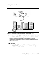
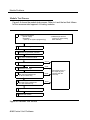
1 For each 400EM tie line/trunk module, for jacks numbered 1 through 4 in
Figure 2-11, check Form 3c, incoming Trunks: Tie, for E&M signaling
type.
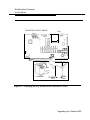
Set the dual in-line packaging (DIP) switches on the front of the 400EM Tie
Trunk module according to the E&M signaling type settings listed in Table 2-4
and Table 2–5 and shown in Figure 2–11. The default E&M signal does not
require any adjustments in the DIP switches.
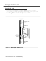
2 Remove the protective cover from each module’s gold-finger connector.
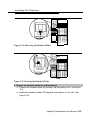
3
Lower the hook on top of the module onto the rod on the top of the
carrier in the appropriate slot. See Figure 2--10.
4 Make sure the connector on the module mates properly with the
connector on the carrier.
5 Swing the module into the slot and firmly push the module into the
carrier until it locks into place.
CAUTION:
To avoid damage, do not force the module. If the module does not insert
easily, press the bottom rear locking tab, remove the module, and
inspect the module and carrier for damage or obstruction.
If there is no damage and no obstruction, reinsert the module, A
damaged carrier or module must be replaced.
Steps 1 through 5 for each module you want to install.
6 Repeat
.
Installing the Control Unit 2-33
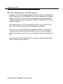
Installing the Modules
Tie Trunks
Tie trunks connect two separate PBX communications systems either directly
or through one or more central offices, as if they were one system at the same
location, In the MERLIN LEGEND Communications System, the 400EM
module is the originating and terminating unit for tie trunk operation.
Tie Trunk Signaling
The 400EM (tie trunk) module can transmit signals in three different formats.
Each format is made up of a specific signaling mode and a specific signaling
type. The DIP switches on the 400EM module allow you to select the signaling
mode for tie trunk transmission. The signaling type is selected through system
programming.
Signaling Modes
There are two signaling modes:
■
E&M. This is a standard interface. The E&M signaling leads are
separate from the transmission leads, requiring a 3-pair wire interface.
■
Simplex. In Simplex, the two signaling leads are superimposed onto
the analog transmission leads, providing a 2-pair wire interface for
connecting two local systems at minimal cost.
Protected or Unprotected
Depending on the type of tie trunk installation, protective resistance may be
installed to protect the circuit from outside interference from high-voltage
transients or voltage fluctuations. In Simplex mode, the circuit always requires
protective resistance. The E&M mode can be either protected or unprotected,
depending upon the location of the distant PBX.
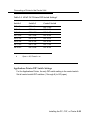
Signaling Types
Three different signaling types combine with the signaling modes, Together
these create the proper signaling format for each system. Signaling types in
each mode are as follows:
2-34 Installing the Control Unit
Installing the Modules
E&M Mode
—Type 1 Standard (default factory setting). This setting is used to
connect two systems through telephone company facilities.
—Type 1 Compatible. This setting connects two systems directly
(without using telephone company facilities).
Simplex Mode
—Type 5. This setting is used on 4-wire (2-pair) circuits.
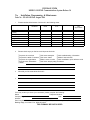
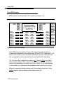
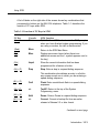
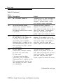
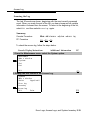
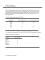
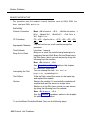
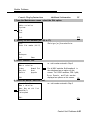
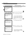
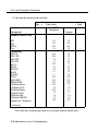
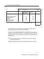
400EM (Tie Trunk) Module DIP Switches
During installation of 400EM (Tie Trunk) modules, refer to Table 2-4 and
Table 2-5, and to Figure 2-11 for the correct DIP switch settings for varying
signaling protocols.
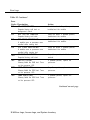
Table 2-4. Setting the 400EM (Tie Trunk) Module DIP Switches
Ports
DIP
(as numbered in
Figure 2-11)
Switch
Position
1
2
4
1
3
2
3
4
5
6
7
8
9
10
Signaling Type
1S (Default)
and 1C
1C and 1S
Unprotected
Protected
E&M Mode E&M Mode
ON
OFF
OFF
ON
OFF
OFF
OFF
OFF
OFF
OFF
OFF
ON
OFF
ON
OFF
OFF
OFF
OFF
OFF
OFF
5
Simplex
Mode
OFF or ON
OFF or ON
ON
ON
ON
OFF or ON
OFF or ON
ON
ON
ON
Installing the Control Unit 2-35
Installing the Modules
NOTE:
DIP switches 1, 2, 6 and 7 determine whether the tie trunks are protected or
unprotected. DIP switches 3, 4, 5, 8, 9, and 10 determine the mode. Simplex
mode is always protected. Therefore the Protected/Unprotected settings for
DIP switches 1, 2, 6 and 7 have no effect.
The successful implementation of a tie trunk format is dependent upon
matching the characteristics of both the PBX systems it connects. The
preferred signaling formats for a tie trunk originating in the system are shown
in Table 2–5 below.
Table 2-5. Signaling Formats for the 400EM (Tie Trunk) Module
Preferred Signaling Format
Installation Situation
From System
To
MERLIN II
System
25/75/85
or DEFINITY
System
25/75/85
or DEFINITY
Dimension PBX
Dimension PBX
Other Systems
Other Systems
MERLIN
LEGEND
System
Distant Location
Protected or Signaling
Unprotected Mode/Type
Protected or
Unprotected
Distant
Location
Signaling
Mode/Type
Same site
co-located
Same site
co-located
Type 5 Simplex N/A
Type 5 Simplex N/A
Type 5 Simplex N/A
Type 5 Simplex N/A
Inter-office
Type 5 Simplex N/A
Type 5 Simplex N/A
Same site
co-located
Inter-office
E&M Type 1 C
(Compatible)
E&M Type 1C
(Compatible)
E&M Type 1 C
(Compatible)
E&M Type 1 C
(Compatible)
Type 5 Simplex
E&M Type 1 S
(Standard)
E&M Type 1 S
(Standard)
E&M Type 1S
(Standard)
E&M Type 1 S
(Standard)
Type 5 Simplex
Same site
co-located
Inter-office
Same site
co-located
or inter-office
2-36 Installing the Control Unit
Unprotected
Protected
Unprotected
Unprotected
N/A
Unprotected
Protected
Unprotected
Requires a
protection unit
N/A
Installing the Modules
400 EM
Module
I
Switches
1 through 5
control
Port 4
(1C. E&M
unprotected)
Switches
6 through 10
control
Port 3
(1C. E&M
protected)
Switches
1 through 5
control
Port 2
(5 simplex)
Switches
6 through 10
control
Port 1
(1C. E&M
protected)
I
1
Figure 2-11. 400EM Module Sample Dip Switch Settings for Signaling Types
1C and 5
Installing the Control Unit 2-37
Installing the Modules
Labeling
1
After all modules have been installed, label all jacks with the numbered
labels provided with the feature module.
■ Line/trunk
labels have green numbers on off-white background.
■ Telephone
labels have blue numbers on off-white background.
See Figure 2-12 for the locations of line/trunk jacks and telephone jacks on
each module, and label them as described next.
2 Label each line/trunk jack on the modules sequentially, 1 through 80.
Begin with the module in slot 1, numbering from bottom to top on each
module and working from left to right across the carrier(s).
The 100D module has 24 numbers assigned to the line/trunk jack.
3 Label each telephone jack sequentially, 1 through 144. Begin with the
module in slot 1, numbering from bottom to top on each module and
working from left to right across the carrier(s).
CAUTION:
The 008 OPT module is assigned 12 logical IDs, and the last four
numbers are not assigned to jacks. For example, if the previous module
(on the left) is labeled with logical IDs 1 through 8, label the 008 OPT
jacks with logical IDs 9 through 16. Skip numbers 17 through 20. When
you label the next module (on the right), label the first jack as logical ID
21.
2-38 Installing the Control Unit
Installing the Modules
PFT Jack
*
8
5
4
Line/Trunk or Off-Premise
Telephone Jacks on
008 OPT Module
1
8
Extension
Telephone
Jacks (Analog or Digital)
1
* These four jacks are
used for extension
telephones on the 012 Module.
Figure 2-12. Line/Trunk and Telephone Jack Locations on Each Module
Installing the Control Unit 2-39
Replacing a Module
Replacing a Module
CAUTION:
This section does not apply to the processor or power supply.
Although the system allows you to remove and replace modules without
affecting call processing, partially inserting and removing a module can
cause a cold start.
To add a 100D module or change any of its DS1 parameters, the system
must be idle.
When you replace a module, use the same module type. For example,
do not put a 008 MLX module in place of a 400 GS/LS/TTR module. If a
module is replaced with another type of module, or if a module is added
to the system without powering down the system first, a cold start
(System Reset) occurs.
If you move any module to a different slot, be sure to renumber the
modules by selecting Board Renumber from system programming. See
System Programming for information about board renumbering.
NOTE:
You can remove and replace line/trunk and extension modules with the
system power on, without affecting normal call processing.
2-40 Installing the Control Unit
Replacing a Module
To remove and replace a module, follow the steps below, Refer to Figure 213.
1 Busy-out or reset the module. (Busy-out is recommended.)
2 Label all cords (if they are not labeled already) and then unplug them
from the module.
For information about labeling trunk and extension cords, see Chapter 3,
“Installing Telephones and Adjuncts” and Chapter 4, “Connecting the Control
Unit to the Network Interface.” For instructions on checking unlabeled wiring,
see “Checking Unlabeled Wiring” in Chapter 3 of the Maintenance and
Troubleshooting guide.
3 Run a demand test by entering the test mode.
4
Power down the system, if required. See “Powering Down the System,”
later in this chapter, for instructions.
5
Remove the module by pushing up firmly on the tab at the bottom rear of
the module.
6 While holding up the tab, swing the bottom of the module towards you
and away from the carrier.
7
Lift up the module to disengage it from the rod on the top of the carrier.
8 Inspect the module for visible damage.
9
Insert the new module. See Figure 2-10.
10 Restore the module. Refer to Chapter 7, “Initializing and Testing the
System,” for instructions.
11 Connect the trunk and extension cords.
12 Attach a tag, error printout, and any information that will help identify any
visible problems or failure symptoms.
Installing the Control Unit 2-41
Replacing a Module
Figure 2-13. Removing Modules from the Carrier
2-42 Installing the Control Unit
Connecting the Control Unit to an AC Outlet
Connecting the Control Unit to
an AC Outlet
CAUTION:
Make sure the AC outlet has been tested for proper grounding. The
outlet should be 117-V AC, 60-Hz, 3-wire (phase, neutral, ground). See
“AC Outlet Tests,” earlier in this chapter, for instructions.
To prevent someone from accidentally shutting off the power, do not
connect the control unit to a switch-controlled outlet. The AC outlet
should be within 5 ft. (152 cm) of the control unit.
To connect the control unit to a dedicated AC outlet, follow the steps below.
1 Turn the basic carrier’s power supply switch to the OFF position.
2 Turn off the power supply switches on the expansion carriers.
3
Unplug the power cords from any auxiliary power units.
4
Plug one end of the power cord into the AC INPUT connector just below
the power switch on the front of the basic carrier’s power supply.
5
Plug the other end of the power cord into the AC outlet, allowing at least
1 ft. (30.4 cm) of slack in the cord.
6
Repeat Steps 4 and 5 for each expansion carrier.
CAUTION:
Do not attach the power cord(s) to any building surfaces.
Installing the Control Unit 2-43
Powering Up the System
Powering Up the System
CAUTION:
Follow the procedure below to power up the system only if the system is
completely installed, failure to comply with this procedure can result in
shock hazard or damage to the equipment.
1 Turn on the power switch for each expansion carrier: start with the power
supply in the rightmost carrier.
The green power lights on each expansion carrier power supply should turn
on.
2 Turn on the power switch on the basic carrier power supply.
The dot on the one-character display LED flashes.
The green light on the power supply should turn on.
The red light on the processor should turn on for 15 to 45 seconds and
then turn off.
All indicators on the 100D and 400EM line/trunk modules (if present)
should turn on and then off. They remain off when the modules are
idle.
3 If any of these conditions are not met, refer to Maintenance and
Troubleshooting.
2-44 Installing the Control Unit
Powering Down the System
Powering Down the System
You may need to power down the system for troubleshooting during
installation, or to add new equipment to the carrier.
CAUTION:
Follow these steps in the exact sequence.
To power down the system, follow the steps below.
1 Turn off the power supply on the basic carrier.
2
Turn off the power supplies on the expansion carriers.
3
Unplug any auxiliary power units.
Because the power supplies are already off, the sequence for removing
auxiliary power cords is not important.
Unplug the system from the AC outlet.
4
Installing the Control Unit 2-45
Powering Down the System
2-46 Installing the Control Unit
Installing Telephones and
Adjuncts
The control unit supports the MLX-10, MLX-10D, MLX-10DP, MLX-20L, and
MLX-28D telephones, with or without Direct Station Selectors (DSSs), as well
as analog multiline and single-line telephones. It also supports various
adjuncts, which may require Multi-Function Modules (MFMs) or other adapters
for installation.
This chapter provides installation instructions for the following procedures:
Installing Multi-Function Modules
Installing adjuncts
Installing Direct Station Selectors
Assembling MLX telephones
Connecting telephones to the control unit
To connect data equipment to the system, see Chapter 6, “Connecting Data
Equipment.” To connect the MERLIN PFC, see Chapter 8, “Installing
Applications.”
Installing Multi-Function Modules
The Multi-Function Module (MFM) is an optional adapter that provides a
modular jack connection to MLX telephones for the two classes of adjuncts
listed below:
Installing Telephones and Adjuncts 3-1
Installing Multi-Function Modules
Tip/ring (T/R) devices such as single-line telephones, fax machines,
modems, and credit card verification terminals. Once connected, the
MLX telephone and adjunct work independently of each other. This
means they can send and receive calls at the same time. The MFM is
the only T/R adapter you can use with MLX telephones.
Supplemental alerts such as bells, chimes, horns, and strobes. These
alerts notify people in noisy areas of incoming calls.
Considerations
Review the following items before you begin the procedure.
If you install an MFM, do so before you assemble the MLX telephone.
You must connect the KS 22911 power supply to an electrical outlet
within 50 ft. (15 m) of cord length of the MLX telephone.
If you connect an MFM and two DSSs to a telephone, you must install
a 406743419 power unit.
If a wall jack is more than 7 ft. (213 cm) from an MLX telephone, you
must use a longer D8W cord.
The MFM uses one of the two channels when it is active, This means
that when an adjunct, such as a fax machine, and the MLX telephone
are in use at the same time, Voice Announce to Busy is not possible.
(Voice Announce to Busy is a feature that allows users to be paged on
the speakerphone even if they are on a call.)
The MFM has two jumper blocks that are factory-set for T/R operation.
The MFM is packaged with the following items, shown in Figure 3-1:
— KS22911 power supply
— 400B or 400B2 adapter
— D6AP cord
3-2 Installing Telephones and Adjuncts
Installing Multi-Function Modules
400B Adapter or 400B2 Adapter
●
✎
❆
✌
Power Supply
(KS22911)
I
D6AP Cord (7 feet long)
Multi-Function Module
Figure 3-1. Multi-Function Module Packing List
RISK OF ELECTRICAL SHOCK: Follow all warnings and cautions.
WARNING:
Only a qualified technician should install, repair, or set options for an
MFM.
Do not touch the circuitry on the MFM. Touching the circuitry may result
in component damage from electrostatic discharge.
Installing Telephones and Adjuncts 3-3
Installing Multi-Function Modules
Before installing an MFM, disconnect all trunk and/or power cords that
are attached to the MLX telephone. This is to ensure that no hazardous
voltages are present during installation. Ringing voltage from the MFM
attached to the MLX telephone can cause electrical shock if
adjustments are made while the cords are connected.
Deskstand
Telephone
Base
Card
Tray
Line
Cable
Figure 3–2. Removing the User Card Tray and Line Cable
To install or replace an MFM and change its pin settings, follow these steps.
NOTE:
If you are installing or replacing an MFM in a wall-mounted MLX-10, MLX-10D,
or an MLX-10DP telephone, start at Step 3.
1 Place the telephone face down on a flat surface; remove the user card
tray and line cable from the bottom of the deskstand. See Figure 3-2.
3-4 Installing Telephones and Adjuncts
Installing Multi-Function Modules
Pull Up
and
Away
Press
Center Tab
Figure 3-3. Releasing the Deskstand
2 Release and remove the deskstand from the telephone, See Figure 3-3
and Figure 3-4.
a Press on the top rear center of the deskstand to release the tab.
b Pull the deskstand up toward you and swing away from the telephone.
Installing Telephones and Adjuncts 3–5
Installing Multi-Function Modules
Lift
out of
Center
Slot
Figure 3-4. Removing the Deskstand
c
Lift the deskstand out of the locating slot in the telephone base and place
to one side.
3-6 Installing Telephones and Adjuncts
Installing Multi-Function Modules
Figure 3–5. Releasing the Module Cover Screw
3 Release and remove the module cover. See Figure 3-5, Figure 3-6, and
Figure 3-7.
a Use a screwdriver to remove the screw in the lower righthand corner of the
module cover.
Installing Telephones and Adjuncts 3–7
Installing Multi-Function Modules
Pull Up and Away
Press
Center Tab
to Release
MFM
Module
Cover
Locating
Slot
Figure 3-6. Releasing the Module Cover
b Press the center of the right side of the module cover with one hand to
release the locking tab.
c
Swing open the module cover to release it from the left side locating slot.
3-8 Installing Telephones and Adjuncts
Installing Multi-Function Modules
Lift
Out of locating Slot
Figure 3–7. Removing the Module Cover
d Lift module cover out of locating slot and place to one side.
Installing Telephones and Adjuncts 3–9
Installing Multi-Function Modules
Locking Tab
Line Jack
Handset Jack
/
// .
Locking Tab
Socket —
Connector
Pins
Locking Tab
Figure 3-8. Removing an MFM Module
4 To install a new MFM, go to Step 5. To reset jumpers on an existing MFM,
go to Step 6. To remove an existing MFM, continue (see Figure 3-8).
a Disconnect any cords attached to the phone and note the connections so
that you can reconnect the cords to the appropriate jacks later.
b Locate the MFM locking tabs on the top and bottom of the telephone base,
then spread the tabs apart to release the MFM.
c Grasp the MFM by the edges and pull it up to free the connector pins. Do
not touch the Connector pins.
d Set the MFM aside on a clean surface.
3-10 Installing Telephones and Adjuncts
Installing Multi-Function Modules
Locking Tab
Socket
Connector
Pins
Locking Tab
Line Jack
Handset Jack
Locking Tab
Figure 3-9. Installing an MFM Module
5 Install the new MFM. See Figure 3-9.
a Hold the MFM circuit board by the edges with the long connector pins
facing the socket. Take care not to touch the connector pins.
b Lower the MFM to insert the pins into the socket in the telephone base,
c Press firmly on the MFM board to snap the locking tabs into place. The
connector pins and tabs must be secure.
Installing Telephones and Adjuncts 3-11
Installing Multi-Function Modules
Multi-Function Module
.
/
Pins
and
Jumper
Placement
w
x
Y
z
T/R Operation Setting
A, B, W and Y
SAA Setting
A, C, X and Z
Figure 3–10. Setting and Adjusting the MFM Jumpers
6
Set or adjust the MFM jumpers for either a T/R device or a supplemental
alert device. See Figure 3-10.
a Pull the four connectors off of the MFM module.
b Place the connectors over the appropriate pins for the required operation,
and push down to secure into place.
3-12 Installing Telephones and Adjuncts
Installing Multi-Function Modules
MFM Jack Guard Cover
Figure 3-11. Removing the Jack Guard
7 To remove the jack guard, see Figure 3-11.
a If the module cover has a square jack guard that protects the TEL/OTHER
jack area, grasp and twist the guard to remove it.
Save the jack guard if you are wall-mounting an MLX-10 or MLX-10D
telephone.
Installing Telephones and Adjuncts 3-13
Installing Multi-Function Modules
Lower
Cover
Into Locating Slot
Figure 3–12. Placing the Module Cover into the Locating Slot
8 To replace the module cover, see Figure 3-12, Figure 3-13, and
Figure 3-14.
a Place the locking tab on themodule cover into the slot on the left side of
the telephone.
3–14 Installing Telephones and Adjuncts
Installing Multi-Function Modules
Lower and
Press Into
Center Slot
to Secure
Figure 3-13. Lowering and Locking the Module Cover
b
Lower the cover to the right and press firmly into the center slot to lock the
tab in place. The tab must be secure.
Installing Telephones and Adjuncts 3-15
Installing Multi-Function Modules
Figure 3-14. Replacing and Tightening the Module Cover Screw
c Replace and tighten the module cover screw that you removed in Step 3.
3–16 Installing Telephones and Adjuncts
Installing Multi-Function Modules
Lower
Into Inner
Center Slot
Figure 3-15. Replacing the Deskstand
9
Replace the deskstand. See Figure 3-15. If you are wall-mounting an
MLX-10, MLX 10D, or MLX-10DP telephone, go to Step 11; otherwise,
continue with Step 9a.
a
Place the tab on the narrow edge of the deskstand, into the locating slot
on the telephone base.
Installing Telephones and Adjuncts 3-17
Installing Multi-Function Modules
Lower
and
Press Into
Center
slot
Figure 3–16. Lowering the DeskStand and Locking into Place
b Lower the deskstand and lock into place.
3-18 Installing Telephones and Adjuncts
Installing Multi-Function Modules
Deskstand
Telephonet
Base
Card
Tray
Line
Cable
Figure 3–17. Replacing the User Card Tray and Line Cable
10
Replace the user card tray and line cable. See Figure 3-17.
a Insert the user card tray at an angle, then lower and slide into the
deskstand.
b Replace the line cable into the line jack in the deskstand.
Installing Telephones and Adjuncts 3-19
Installing Multi-Function Modules
Pull Up
Press
Center Tab
Card
Tray
Deskstand
Telephone
Base
Line
Cable
Figure 3-18. Adjusting the Deskstand Height
11 Adjust the deskstand height. See Figure 3-18.
a To change the deskstand’s height from low to high, press the top rear
center of the deskstand to release the tab.
b Pull the deskstand up and insert the tab into the slot in the module cover.
c To readjust the stand, see the instructions on the bottom of the card tray.
12 Power up the telephone. See Figure 3-19.
a Plug the D8W cord from the telephone into the 8-conductor (large)
modular jack of the 400B or 400B2 adapter.
3-20 Installing Telephones and Adjuncts
Installing Multi-Function Modules
Wall Jack
AC Power
Outlet
D6AP
Power
Supply
400B2 Adapter
D8W
Dss
Dss
I
Figure 3–19. Powering Up the Telephone after Installing the MFM
b Connect one end of the D6AP cord to the 2-conductor (small) modular jack
on the 40013 or 40092 adapter, and plug the other end into the modular
jack of the 406943837 power supply. The total length of the cords
connecting the power supply to the MLX telephone must be less than or
equal to 50 ft. (15 m).
CAUTION:
Do not plug the D6AP cord into the 8-conductor (large) modular jack on
the 400B or 400B2 adapter; doing so can cause electrical damage to
the control unit and to the telephone.
Installing Telephones and Adjuncts 3-21
Installing Adjuncts
c Plug the power supply into a 117-V AC outlet that is not controlled by a
wall switch.
d Insert the plug end of the 400B or 400B2 adapter into the wall jack.
13 Test the MFM for T/R operation.
See “Testing MLX Telephones with MFMs” in Chapter 7.
14 Attach the adjunct to the MFM. See “Installing Adjuncts.”
Installing Adjuncts
This section provides general instructions for connecting most adjuncts.
NOTE:
If you need to connect the adjuncts differently from the instructions on the
system forms, record each jack and adjunct change on the appropriate
system numbering form. See Appendix A, “System Numbering Forms. ”
1 Connect one end of the cord packaged with the adjunct (usually a D4BU
cord) to the adjunct.
See the documentation packaged with the adjunct for instructions.
2
Check the system form for the adjunct you want to connect. Then refer to
the appropriate step below.
■
To connect an adjunct to an MLX telephone, go to Step 3.
■
To connect an adjunct to a single-line telephone, go to Step 4.
■
To connect an adjunct to an analog multiline telephone, go to Step 5.
■
To connect an adjunct to a 012 module, go to Step 6.
When you connect adjuncts to telephones, make sure you route the adjunct
and D8W telephone cords through the cord channel. See Figure 3–20.
3 Insert the other end of the adjunct cord into the TEL/OTHER jack on the
back of the MLX telephone. Go to Step 7.
3–22 Installing Telephones and Adjuncts
Installing Adjuncts
To
Adjunct
D8W
Cord Channel
D4BU Connects to
TEL/OTHER
Jack
Line
To
400B
MLX-10™
Desk Telephone
D8W
Line
MLX-10™
Wall-Mounted Telephone
Figure 3–20. Routing the Cord(s) Through the Cord Channel
4 To connect an adjunct to a single-line telephone:
a Connect a 26A2 bridging adapter to the telephone.
b Connect the cord from the adjunct to the bridging adapter.
c Reconnect the cord from the control unit to the bridging adapter.
d Go to Step 7.
Installing Telephones and Adjuncts 3–23
Installing Adjuncts
5 To connect an adjunct to an analog multiline telephone:
a Connect a 4-pair cord to the OTHER jack on the telephone.
b Connect the other end to the VT jack on a General Purpose Adapter
(GPA).
c Connect the cord from the adjunct to the TEL/EQUIP jack on the GPA.
d Go to Step 7.
Refer to “General Purpose Adapter” below for additional information.
6 lnsert the other end of the adjunct cord directly into the port for the
logical ID on the 012 module as indicated on the system form. Go to
Step 7.
7 Test the adjunct by dialing its associated extension.
General Purpose Adapter
A General Purpose Adapter (GPA) lets you connect a T/R device--such as a
single-line telephone or modem —to an analog multiline telephone. The device
must be touch-tone, not rotary.
NOTES:
1. The GPA is intended for answer-only service, unless the telephone has
direct access to a line. It does not have touch-tone receivers or pulse dial
detectors; therefore, the associated analog muitiline telephone must dial
calls.
2. The GPA cannot be used with a MERLIN II System Display Console.
3. When the system forms indicate a GPA for installation of an adjunct, follow
the steps below.
1 Plug one end of a 4-pair adjunct D8AC cord into the VT jack on the back
of the GPA.
2 Plug the other end into the OTHER jack on the underside of the analog
multiline telephone.
3 Plug the cord from the adjunct into the TEL EQUIP jack on the GPA.
3-24 Installing Telephones and Adjuncts
Installing Adjuncts
4
Slide the switch on the back of the GPA to the setting that provides the
required service.
Basic. This setting is used to dial and answer calls from an analog
multiline telephone or to attach a T/R adjunct such as a single-line
telephone or answering machine. Incoming calls ring only on the
analog multiline telephone. This setting also allows the user to
originate and receive calls on the telephone while using a computer
with a modem that is attached to the GPA. However, if this setting is
used, data calls cannot be answered automatically.
Join. This setting is used to add a recording device or a single-line
telephone to a call that is in progress on the telephone. You cannot
originate or answer calls on this setting,
Automatic. Use this setting when a GPA connects a modem to an
analog multiline telephone for answering calls or answering machine.
Dial Dictation Devices
You can connect a dial dictation device to one of the following, as described
earlier in this chapter:
■
012 module
■
MLX telephone with an MFM
■
GPA and analog multiline telephone
You can also connect a dial dictation device through a commercially available
trunk adapter or a Universal Paging Access Module (UPAM) on a loop-start
line/trunk jack with an external power supply unit.
NOTE:
Using any of the devices listed above, you cannot connect dial dictation
devices that require contact closure. You can connect such equipment
through a UPAM, however, since it provides contact closure for the device.
Installing Telephones and Adjuncts 3-25
Installing Adjuncts
Fax Machines
You can connect a fax machine to one of the following, as described earlier in
this chapter:
■
012 module
■
MLX telephone with an MFM
The fax machine can send and receive fax calls independently of the
telephone. Dial calls either from the fax machine’s dialpad or from an
associated single-line telephone.
Do not use a GPA to connect a fax machine to the system, because the fax
machine cannot dial out through the GPA.
Group Calling Delay Announcement Devices
You can connect a group calling delay announcement device to one of the
following, as described earlier in this chapter:
■
012 module
■ MLX
telephone with an MFM
■ GPA
and analog multiline telephone
An industry-standard announcement device, such as a Digital Announcer
Unit, provides Night Service information or announces to a caller that calling
groups are busy.
Credit Card Verification Terminals
You can connect a credit card verification terminal to one of the following, as
described earlier in this chapter:
■
012 module
■
MLX telephone with an MFM
3-26 Installing Telephones and Adjuncts
Installing Adjuncts
If you connect a credit card verification terminal to an MFM, the terminal can
place and receive calls independently of the MLX telephone.
Do not use a GPA to connect a credit card verification terminal to the system,
because the terminal cannot dial out through the GPA.
Headsets
Headsets are designed for hands-free telephone use and consist of several
components, depending upon whether manual or one-touch operation is
used. Any AT&T headpiece works in either mode.
Headpieces
Six different headpieces are available. Each is light, comfortable, and uses a
transparent voice tube to eliminate a cumbersome large microphone. Each
comes with a 10-ft. (305-cm) coiled cord and a quick-disconnect latch.
®
Mirage . This is a small, almost unnoticeable, monaural headset that
uses a disk-shaped receiver. It can be worn on either ear, instead of a
headband or ear tip. This headset is not useful in noisy environments.
®
StarSet . This monaural headset is worn without a headband. It uses
a soft, pliable ear tip that provides high-quality sound yet allows you to
hear other conversations or instructions in the workplace.
®
Supra Monaural. This monaural headset has an adjustable
headband. It offers a soft, comfortable ear cushion that reduces
surrounding noise, making it easier to understand the caller.
Supra Monaural Noise-Canceling (NC). Same as above with noisecanceling microphone to reduce background noise by up to 75
percent.
Supra Binaural. Sound in both ears with soft ear cushion and
adjustable headband.
Supra Binaural Noise-Canceling (NC). Same as above with noisecanceling microphone on flexible boom features windscreen and
reduces background noise transmission by up to 75 percent.
Installing Telephones and Adjuncts 3–27
Installing Adjuncts
Manual Operation (Analog Multiline
Telephones Only)
Manual operation is appropriate when a headset is used occasionally. You
pick up the handset to answer a call and replace it to hang up. The headset
consists of the headpiece, and a modular base unit. The headpiece plugs into
the modular base unit, and the modular base unit connects to the telephone
through the HANDSET jack on the side of the telephone. The telephone
handset is plugged into the modular base unit. The modular base unit allows
you to adjust the incoming volume, switch between the headset and handset
as needed, and temporarily mute the line. (See Figure 3–21.)
One-Touch Operation (All Telephones)
One-touch operation allows you to touch a button to answer a call. On analog
multiline telephones, use a headpiece with a plug prong base unit and an
adapter (502C). The headpiece connects to the plug prong’ base unit, which in
turn connects to the adapter. The adapter plugs into the OTHER jack on the
underside of the telephone, The plug prong unit provides switchhook control for
answering calls by pressing a button. You can also adjust the incoming
volume. On MLX telephones, the headpiece is attached to a modular base unit,
which is attached to the telephone, The handset is also attached to the modular
base unit. (See Figure 3-21.)
3-28 Installing Telephones and Adjuncts
Installing Adjuncts
OTHER Jack
(underside)
Headpiece
Headpiece
Modular
Base
Unit
Modular
Base
Unit
502C Adapter
Plug Prong Base Unit
Headpiece
Handset
Jack
Handset Jack
Manual Operation
(Analog Multiline
Telephones only)
One-Touch Operation
(Analog Multiline Telephones)
One-Touch Operation
(MLX Multiline
Telephones only)
Figure 3-21. Manual and One-Touch Headset Operation
Loudspeaker Paging Systems
Use a loudspeaker paging system to page co-workers and make
announcements. You connect the paging system to the jack of an LS or GS
line/trunk that is programmed for paging.
Figures 3-22, 3–23, and 3–24 show various configurations for single-zone
paging. Figures 3-25 and 3-26, later in this chapter, show single-zone and
multizone paging configurations that include background music through a
Magic on Hold audio source. Bidirectional paging, also called talk-back, is
shown in Figure 3–26.
Installing Telephones and Adjuncts 3-29
Installing Adjuncts
Dual-Tone Multifrequency (DTMF) Signaling
You can connect external paging systems that use dual-tone multifrequency
®
(DTMF) signaling, such as PagePac Plus with Zone Expansion Unit paging
systems, to an LS or GS line/trunk jack programmed for paging operation,
including bidirectional paging operation (talk-back). PagePac Plus does not
require an adapter.
Zone paging systems, such as the PagePac series, require one LS or GS
jack. You can use any zone once the paging jack is activated.
You must use a Universal Paging Access Module (UPAM), or PagePal (for
PagePac series systems other than PagePac Plus) to connect a paging
system that requires contact closure, an impedance-matching transformer, or
both.
Use a Loop Start Trunk Adapter when a customer-supplied paging system
does not require contact closure.
3-30 Installing Telephones and Adjuncts
Installing Adjuncts
PAGEPAC
PLUS
OUTPUTS
Speaker
PAGING
INPUT
D4BU
Cord
MUSIC
IN
117
VAC
Control Unit
Figure 3-22. Single-Zone Paging with PagePac Plus
Installing Telephones and Adjuncts 3-31
Installing Adjuncts
CUSTOMER-SUPPLIED AMPLIFIER
OUTPUTS
voice
coil
Speaker
J5
J4
PAGE INPUT
D4BU
Cord
J1
117VAC
HARRIS/DRAC0N
Model
Loop-Start Trunk
Adapter
22050-900
● J1
J2
I
/
D4BU
Cord
+24V
POWER
CABLE*
GND
,
I
Control Unit
117VAC
WHEELOCK
POWER SUPPLY
MODEL EPS-2401
WARNING! The black wire from the LS trunk adapter power cable
must be connected to the + (positive) input of the Wheelock PS. The grey on
black wire must be connected to the - (negative) input.
Figure 3–23. Single-Zone Paging with Customer-Supplied Amplifier
3-32 Installing Telephones and Adjuncts
Installing Adjuncts
PAGEPAC 20
OUTPUTS
Speaker
D4BU
Cord
Connection
Block
103A
PAGING
INPUT
MUSIC
IN
117
VAC
12345678
13
Universal
Paging
Access
Module
14
15
103A
4 PT
12345678
5 PR
BOGEN
Model PAM
CC405258013
DlW
ACCESS MODE
AUTO-MANUAL
29 R
30 T
PBX
26
GND
Control Unit
Set the
Access Mode
switch to
MANUAL
27
POWER
CABLE
+24V
+
117VAC
WHEELOCK
POWER SUPPLY
MODEL EPS-2401
Figure 3-24. Single-Zone Paging with UPAM
Installing Telephones and Adjuncts 3-33
Installing Adjuncts
MERLIN Identifier
MERLIN Identifier™ allows the use of local telephone company caller
identification services to receive, store and use calling party number
information. Before installation, verify that this service provided by the Central
Office is available on the lines to be connected. Each MERLIN Identifier
consists of the following:
A control unit, which must be located near the MERLIN LEGEND
control unit
Up to four individual display units, which can be mounted on analog
multiline telephones or wall-mounted for both analog and MLX
telephones
An administrative keyboard
Optional equipment includes an administrative display, a PC, and a serial
printer.
For detailed instructions, see MERLIN Identifier Installation and
Administration.
When MERLIN Identifier is used with MLX telephones, a pair of installer-wired
104A termination outlets are required for each MLX set that is connected to a
MERLIN Identifier display unit.
Modems
You can connect a modem to one of the following:
■ Single-line
telephone
■ MLX
telephone with an MFM
■ GPA
and analog multiline telephone
3–34 Installing Telephones and Adjuncts
Installing Adjuncts
NOTE:
When a modem is connected to the TEL/OTHER jack on the MLX telephone
equipped with an MFM, data calls can be made from the modem
independently of the MLX telephone. Users dial data calls from the data
terminal keyboard.
See Chapter 6, “Connecting Data Equipment,” for complete information on
connecting data equipment.
Music On Hold and Magic on Hold
You can connect a Music On Hold device to an LS or GS line/trunk jack
programmed for Music On Hold. The system supports one such connection,
®
either Magic on Hold or a customer-owned music source, The external music
coupler (PEC 61398) uses an 8-ohm music source and two attenuation
controls for setting the music level.
NOTES:
1. PagePac Plus equipment can be used with a loudspeaker system to
provide music. Or it can provide paging without a music coupler.
2. If the equipment uses rebroadcasted music or other copyrighted
materials, the customer is required to obtain a copyright release and may
also require a copyright license from, and pay license fees to, a third
party, such as the American Society of Composers, Artists, and Producers
(ASCAP), or Broadcast Music Incorporated (BMI). To bypass the release
and license requirement, the customer can purchase a Magic on Hold
system from AT&T, which does not require such a license.
Figures 3-25 and 3–26 show different background music configurations with
single-zone and multizone paging.
Installing Telephones and Adjuncts 3-35
Installing Adjuncts
PAGEPAC 20
OUTPUTS
PAGING
INPUT
Speaker
D4BU
Cord
Control
Unit
Connection
Block
103A
12345678
MUSIC
PORT
I
103 A
12345678
Connection
Block
MUSIC
IN
117
VAC
13 UNIVERSAL
14
PAGING
ACCESS
15
MODULE
4 PT
5 PR
BOGEN
Model PAM
CC405258013
ACCESS MODE
AUOT-MANUAL
29 R
PBX
30 T
+24V
D4BU
Cord
Standard
Phono
Patch Cord
POWER
CABLE
Set the
Access MC
switch to
MANUAL
GND
117 VAC
WHEELOCK
POWER SUPPLY
MODEL EPS-2401
BKGD
MOH
OUT
VOL
Music Source
MUSIC IN
Music Coupler
CC405476452
KS-23395 L-2
MAGIC ON HOLD
Figure 3-25. Single-Zone Paging with Background Music and Magic on Hold
3-36 Installing Telephones and Adjuncts
Installing Adjuncts
PAGEPAC PLUS
MUSIC IN
J2
PAGE INPUT
J1
D4BU
Cord
I
MUSIC
PORT
117VAC
P1
P3
CK LS
PAGE INPUT SWITCH
J40
J101
DL
GS
D4BU
Cord
(
.
AmpIiCenter
Controller
Zone
Expansion
Unit
‘(
I
Mic/Speaker
Mic/Speaker
Control
Unit
Standard Phono
Patch Cord
MOH
OUT
Mic/Speaker
BKGD
Music Source
VOL
Music In
Music Coupler
CC405476452
KS-23395 L-2
MAGIC ON HOLD
Figure 3–26. Multizone Paging with Background Music, Magic on Hold, and
Bidirectional Paging (Talk-Back)
Installing Telephones and Adjuncts 3–37
Installing Adjuncts
Supplemental Alerts
Alerting devices notify people working in noisy areas of outside, transferred,
and intercom calls. Connect an alert to one of the following:
■ Single-line
■ MLX
telephone
telephone with an MFM
■ Supplemental
Alert Adapter (SAA) and analog multiline telephone
Alerts compatible with the SAA include horns, bells, chimes, and strobes. See
“Supplemental Alert Adapter” for installation instructions.
NOTE:
The MFM in SAA mode and SAA support devices operate on 48 V DC.
You can connect alerts operating on 20 through 30 Hz to an MFM in tip/ring
mode or a single-line telephone jack.
Supplemental Alert Adapter
If the system forms indicate a bell, horn, chime, or strobe with an analog
multiline telephone, follow the steps below to install an SAA. See Figure 3–27.
1 Plug the telephone cord into the TELEPHONE jack on the SAA.
2 Plug the cord from the alert device into the ALERTER jack on the SAA.
3 Plug the cord from the telephone wall jack into the CONTROL UNIT jack
on the SAA.
3-38 Installing Telephones and Adjuncts
Installing Adjuncts
Supplemental Alert Adapter
CONTROL
TELEPHONE UNIT
ALERTER
ON OFF
I
I
Telephone
Wall Jack
Alerter
Figure 3-27. Installing the Supplemental Alert Adapter
Unsupported Telephones, Adjuncts,
and Adapters
Do not connect the following analog telephone adjuncts and adapters to the
system. Doing so may cause damage to the device or the system.
Basic Telephone and Modem Interface (BTMI)
Basic Telephone and Modem Interface 2 (BTMI-2)
ATR Interface (ATRI)
Installing Telephones and Adjuncts 3-39
Installing Adjuncts
■ MTR
Interface (MTRI)
■ Off-Premises
■ System
Extension Unit (OPX)
25 Direct Extension Selector (DXS)
See Table 3-1 for additional notes on unsupported telephones and adjuncts.
Table 3–1. Unsupported Telephones and Adjuncts
Model
Notes
51013 Personal Terminals
Digital Communications Protocol (DCP)
DCP telephones
7400 telephones and adjuncts (asynchronous data units
and multiple asynchronous data units) that use DCP and
are supported on the MERLIN II Communications System
MET telephones
Multibutton electronic telephones (METs) and adjuncts
used with the Dimension PBX and Horizon systems
Single-line telephones (with
neon message-waiting lights)
Message light does not work.
Analog telephone adjuncts
Basic telephone modem interface (BTMI); BTMI-2; offpremises extension (OPX) unit; System 25 Direct
Extension Selector (DXS); DSS attached to a 34-button
Deluxe membrane
Single-Line Telephones
Releases prior to Release 3.0 system support the single-line telephones listed
in Table 3–2.
3-40 Installing Telephones and Adjuncts
Installing Adjuncts
Table 3-2. Single-Line Telephones
Model
Description
2500MMGB
2554MMGJ
2500YMGK*
Basic desk telephone
Basic wall telephone
Basic desk telephone with Message light and Recall button; Recall
button used instead of switchhook for features that require a switchhook
flash.
2500SM
Basic desk telephone used with 4A speakerphone
Basic desk telephone with built-in headset jack
2514BMW
Outdoor telephone used with weatherproof enclosure
2526BMG
7101A*
Basic desk telephone with Message light and Recall and Disconnect
buttons. No adjuncts supported.
7102A
Basic desk telephone with Message light lamp and Recall button. The
101 and 201 speakerphones and the 500 headsets are supported. Can
be used for Dower-failure transfer (PFT) extensions.
CS6402UO1A* Basic desk telephone, Feature Phone Model 420. Has built-in
speakerphone, memory, and redial.
Basic desk telephone
2500MMGJ
2500MMGK
Basic desk telephone with Recall button; Recall button used instead of
switchhook for features that require switchhook flash.
Basic desk telephone with jack to support headset adapters and
8102†
speakerphone adjuncts.
Basic desk telephone with a built-in speakerphone with volume control
8110
and Mute button with LED indicator.
500MM
Basic telephones equipped with rotary dials so no system features
requiring * and # can be used. Telephones with neon Message lights are
554BMPA
500SM
not supported.
*
†
Vintage telephone, no longer available for sale or lease
Although the 8102 can be connected to a speakerphone and the8110 has a
speakerphone, they cannot be used for group paging (not supported on
single-line telephones). The auto answer function on the 8110 must be
disabled.
Installing Telephones and Adjuncts 3-41
Installing Adjuncts
Single-Line Telephones in Release 3.0 and Later
In Release 3.0 and later, only single-line telephones with positive disconnect
are fully supported as system telephones (any single-line telephones,
equipped with a ground-start button if necessary, can be used as PFT
telephones). Older single-line telephones can be used with Release 3.0, but
their operation is slightly different. Table 3-3 lists the single-line telephones
supported in Release 3.0 and later.
Table 3-3. Single-Line Telephones Supported by Release 3.0 and Later
Model
Description
2500 YMGL
Basic desk telephone with Message light and Flash button; Flash
button is used instead of the switchhook for features that require a
switchhook flash, such as Transfer and Hold.
8101
Basic desk telephone with Message light and Flash button; Flash
button is used instead of the switchhook for features that require a
switchhook flash, such as Transfer and Hold.
VideoPhone 2500
Picasso StillImage Phone
Provides interactive, small-screen video when both parties use one
Allows 2 parties with Picasso Still-Image Phones to transmit and
simultaneously discuss full-color images which they view over
customer-supplied TV monitor or flat-panel LCD (liquid crystal
display) monitor
Touch-tone outdoor telephone equipped with cast aluminum
housing, armored handset cord with bell ringers
Rotary dial outdoor telephone equipped with cast aluminum
housing, armored handset cord with bell ringers
3129-V(TVVA
3129-WRWA
3129-WAWA
3129-WNWA
Auto dial outdoor telephone equipped with cast aluminum housing,
armored handset cord with bell ringers
Non-dial, automatic ringing on dedicated circuit outdoor telephone
equipped with cast aluminum housing, armored handset cord with
bell ringers
3-42 Installing Telephones and Adjuncts
Installing Direct Station Selectors
Installing Direct Station Selectors
The Direct Station Selector (DSS) is an optional piece of telephone equipment.
You can connect up to two DSSs to an MLX-28D or MLX-20L telephone that is
programmed as an operator console.
Considerations
Review the following items before you begin the installation procedure.
Connect the DSSs before you assemble the MLX telephones.
Auxiliary power is required under the following circumstances:
— An MLX telephone with an MFM and two DSSs requires a
406743419 power unit.
— An MLX telephone without an MFM, but with two DSSs, requires a
406943837 power unit, 400B adapter, and the D6AP cord that is
provided with the MFM.
— An MLX telephone with one DSS and an MFM requires a
406943837 power unit, 400B adapter, and the D6AP cord that is
provided with the MFM.
— If one carrier has three or more MLX telephones, each with a DSS
attached, use a 406943837 power unit, 4006 adapter, and D6AP
cord for each MLX telephone and DSS after the first two.
The total length of cords between the KS22911-L2or406743419
power supply and the MLX telephone must not be more than
50 ft. (15 m).
Do not replace the 2-ft. (61 -cm) D8AC cord (packaged with the DSS)
with a longer cord. Improper operation may result.
Connect each KS22911-L2 power supply to an AC outlet that is not
controlled by a wall switch.
Installing Telephones and Adjuncts 3-43
Installing Direct Station Selectors
To connect a DSS, follow the steps below. If you are connecting two DSSs to
the telephone, unpack the second DSS before you start.
1 Adjust the angle of the DSS.
■ The DSS is packed fully assembled with the deskstand in the low
position. If you prefer the low position, go to Step 2.
■
To adjust the angle of the DSS to the high position:
a Place the DSS face down, on a flat surface.
b Press on the top rear center of the stand to release the tab, then
pull the stand toward you and away from the DSS.
c Insert the tab at the bottom of the stand into the other slot.
d Lower the stand and press the tab at the top into the corresponding
slot on the DSS.
2 Install the D8AC cord on the DSS.
a Plug one end of the D8AC cord into the IN jack on the DSS.
b Route the D8AC cord through the cord channel on the left side of the DSS.
c If you are installing only one DSS, go to Step 4.
If you are installing two DSSs, repeat Steps 1 and 2 for the second DSS,
then go to Step 3.
3 Wire the two DSSs. See Figure 3-28.
a Place the two DSSs side by side and face down.
b Route the D8AC cord from the IN jack on the second DSS (DSS2) through
the cord channel on the first DSS (DSS1).
c
Plug this D8AC cord into the OUT jack on DSS1.
3-44 Installing Telephones and Adjuncts
Installing Direct Station Selectors
D8AC
D8W
Dss
MLX Telephone
DSS 1
D8W
MLX Telephone
DSS 2
D8AC
DSS 1
Dss 2
Figure 3–28. Connecting One or More DSSs
4 Wire the telephone to the DSS unit(s). See Figure 3-28.
a Remove the handset from the telephone, then place the telephone face
down on a flat surface to the right of the upside-down DSS unit(s).
b Plug the D8AC cord from the IN jack on the DSS1 into the DSS jack on the
telephone; then route the cord through the cord channel.
c Plug the D8W line cord into the LINE jack on the MLX telephone. The D8AC
and D8W cords share the cord channel on the telephone.
Installing Telephones and Adjuncts 3-45
Installing Direct Station Selectors
Wall Jack
AC Power
Outlet
-
-
-
I* I
-
D6AP
Power
Supply
400B2 Adapter
D8W
DSS
Figure 3–29. Wiring for Auxiliary Power
5 Turn the telephone and the DDS unit(s) faceup with the telephone now to
the left of the DDS unit(s). See Figure 3-29.
6 Insert one end of the coiled H4DU handset cord into the handset and the
other end into the jack on the side of the telephone.
7 If auxiliary power is not required, plug the D8W cord into the wall jack
and then go to Step 9.
8 If auxiliary power is required, refer to the following steps and Figure
3-29. The combined total length of the D6AP and D8W cords you use
must not be more than 50 ft. (15 m).
a Plug the D8W cord from the telephone into the 8-conductor modular jack
of the 400B or 400B2 adapter.
3-46 Installing Telephones and Adjuncts
Installing Direct Station Selectors
b Connect one end of the D6AP cord to the 2-conductor (small) modular jack
on the 400B or 400B2 adapter, and plug the other end of the D6AP cord
into the modular jack of the 406943837 or 406743419 power supply.
CAUTION:
Do not plug the D6AP cord into the 8-conductor (large) modular jack of
the 400B or 40052 adapter. Doing so can cause electrical damage to
the control unit and to the telephone.
c Insert the plug end of the 4008 or 400B2 adapter into the wall jack.
d Plug the power supply into a 117-V AC outlet.
9 Label the DSS designation cards.
a Pull the tab at the top of the large plastic cover and rotate the cover
towards you.
b Remove the cover and the large designation card.
c Write or type the button assignments on the card, (For DSS1, use the side
that is labeled 00-49 for DSS2, use the side labeled 50-99.)
The button assignments on the designation card should be by dial plan
extension number, not by logical ID port number.
d Replace the card and the plastic cover; make sure the coated side of the
cover is facing up.
e Repeat this step to remove the small plastic cover and to label the small
designation card.
NOTE:
If the MLX telephone attached to the DSS is unplugged from the control unit
and then plugged in again, the display on the telephone may disappear,
Press the Home button to bring back the display.
Installing Telephones and Adjuncts 3-47
Assembling MLX Telephones
Assembling MLX Telephones
You will need to assemble an MLX telephone before connecting it to the
control unit. For all other telephones, skip to “Connecting Telephones to the
Control Unit.”
Considerations
Review the following items before you begin the procedure:
MLX telephones are packed with the deskstand in the low position.
You can use the deskstand as is, raise it to a higher angle, or remove
it. To adjust or remove the stand, see Step 1 of the following
instructions. (The diagram on the bottom of the user card tray also
shows how to adjust the stand.)
You cannot wall-mount MLX-20L and MLX-28D telephones.
If you wish to wall-mount an MLX-10, MLX-10D, or MLX-10DP
telephone, you must remove the deskstand first. (Wall-mounting an
MLX-10D or 10DP telephone can make the display hard to read.)
A 630B Phonemount (not included) is also required to mount an MLX10, MLX-10D, or MLX-10DP telephone on the wall.
To connect an adjunct (such as an alert, modem, or fax machine) to an
MLX telephone, the telephone must have an MFM installed in it. If you
have not already done so, refer to “installing Multi-Function Modules, ”
earlier in this chapter.
3-48 Installing Telephones and Adjuncts
Assembling MLX Telephones
Pull Up
and
Away
Press
Center Tab
Figure 3-30. Adjusting or Removing the Deskstand
To assemble an MLX telephone, follow the steps below.
1 Remove or adjust the deskstand. See Figure 3-30.
■ If you want to leave the deskstand in the low position, go to Step 2.
■
If you want to adjust the angle of the deskstand, or remove it in order
to wall-mount the telephone:
a Place the telephone face down on a flat surface.
b Press on the top rear center of the deskstand to release the tab,
then pull it up towards you.
c Insert the tab into the slot in the module cover to adjust the height.
d To remove the deskstand, continue to pull it up and away from the
telephone.
e Release the deskstand from the front slot.
Installing Telephones and Adjuncts 3-49
Assembling MLX Telephones
To
Adjunct
D8W
D8W
Cord Channel
To
400B
D4BU Connects to
TEL/OTHER
Jack
Line
Line
Ii’
M L X - 1 0T M
Desk Telephone
—
MLX-10™
Wall-Mounted Telephone
Figure 3-31. Connecting the Line Cords
2 Connect the line cords. See Figure 3-31.
Plug one end of the D8W cord into the LINE jack on the bottom of the
phone.
b Route the D8W cord through the cord channel on the back of the
telephone.
c If the telephone is for desktop use, turn it face up and plug the D8W cord
into the wall jack.
a
d
Insert the other end of the coiled H4DU handset cord into the jack on the
side of the telephone.
3-50 Installing Telephones and Adjuncts
Assembling MLX Telephones
Paper
Clip
Figure 3–32. Removing the Extension Label
3 Connect the handset.
Insert one end of the coiled H4DU handset cord into the handset.
4 Label the extension identification card.
a Insert a straightened paper clip into the hole on the side of the plastic
cover while holding your finger on the opposite edge; use the paper clip to
push and lift the cover. See Figure 3-32.
Installing Telephones and Adjuncts 3-51
Assembling MLX Telephones
MLX-10
555-1234
Figure 3-33. Labeling the Extension
b Type or write the assigned extension number on the card. See Figure
3-33.
c
If you are wall-mounting an MLX-10, MLX-10D, or MLX-10DP telephone, go
to Step 5. If you are assembling a desk telephone, go to Step 6.
3–52 Installing Telephones and Adjuncts
Assembling MLX Telephones
Figure 3-34. Removing the Handset Holder
MLX-10
Figure 3-35. Rotating the Handset Holder
5 Prepare the handset holder for wall-mounting.
a Remove the handset holder by pushing it up and pulling it out. See Figure
3-34.
b Rotate the handset holder 180 degrees and replace it in its slot. See
Figure 3-35.
Installing Telephones and Adjuncts 3-53
Assembling MLX Telephones
Figure 3–36. Replacing the Extension Label
6
Replace the extension label and plastic cover.
a Insert one end into the slot and snap the other end into place. See Figure
3-36.
b
If you are mounting an MLX-10, MLX-10D, or MLX-10DP wall telephone, go
to Step 7. If you are assembling a desk telephone, go to Step 8.
7 Wall mounting an MLX-10, MIX-10DP, or MlX-10D telephone.
a Turn over the telephone and remove the jack guard from the TEL/OTHER
jack area; set the telephone aside.
b Unpack the 630B Phonemount and remove the modular jack from the
backplate.
c Route the D8W cord (or DIW cable) through the hole in the backplate and
have it exit at the top of the backplate; leave 10 in. (25 cm) of cord to
connect the telephone. See Figure 3–37.
3-54 Installing Telephones and Adjuncts
Assembling MLX Telephones
Jack Plug
Jack Guard
Mounting Plate
630B
Phone
Mount
Figure 3–37. Mounting the Backplate
d Attach the backplate to the wall; see the instructions provided with the
6306 Phonemount.
e Insert the two short screws provided with the Phonemount into the
mounting plate. Be sure to thread the upper screw through the jack guard.
See Figure 3-37.
Installing Telephones and Adjuncts 3-55
Assembling MLX Telephones
D8W
❑
Mounting
Plate
6306
Figure 3-38. Routing the Cord Through the Backplate
f
Plug the free end of the cord into the LINE jack on the back of the
telephone. Route the cord through the cord channel above the jack. See
Figure 3-38.
g Position the telephone on the mounting plate studs and then slide the
telephone down to lock it in place. To remove the telephone, slide it up
and off.
8
Label the button assignment card.
a Pull the tab at the top of the plastic cover toward you.
3-56 Installing Telephones and Adjuncts
Installing Cordless or Cordless/Wireless Telephones
b Type or write the button assignments on the card.
c
Insert the card and replace the plastic cover. Be sure the textured side of
the cover is facing you.
9 Adjust the contrast on the telephone% display.
■
For an MLX-20L telephone, slide the lever on the top of the telephone.
■
For an MLX-10D, MLX 10DP, or MLX-28D telephone, press the Menu
button and select Cntrst; follow the display prompts.
Installing Cordless or
Cordless/Wireless Telephones
The sections below describe the ways you can connect MDC 9000 cordless
or MDW 9000 cordless and wireless telephones to the system.
MDC 9000 Cordless Telephone
You can connect the base unit of the MDC 9000 to an analog extension jack.
MDW 9000 Cordless/Wireless Telephones
The following is a brief overview of procedures and considerations for
installation of the MDW 9000 telephone, For more detailed information, see the
installation guide that comes with the telephone.
■
If possible, place the radio module of a wireless telephone in the same
room and on the same wall as the MERLIN LEGEND Communications
System control unit.
A minimum distance of 3 ft. is required between the radio base and
the control unit. The radio module must be within 24 ft. of a properly
grounded 3-prong AC outlet that is not controlled by a wall switch and
connects to the control unit through an analog multiline jack with a line
connector.
Installing Telephones and Adjuncts 3–57
Connecting Telephones to the Control Unit
■
The charging base station requires only a three-prong AC outlet that is
not connected to a wall switch.
■
The telephone handset must be within range of the radio base. The
indoor range is 400 through 600 ft. and the outdoor range is up to
1000 ft.
■
Except while charging, the handset does not need to be located near
the charging base.
Connecting Telephones
to the Control Unit
The way you connect telephones to the control unit depends on the number of
telephones you are connecting. For 24 telephones or less, use a direct
connection. For 25 telephones or more, use cross-connect fields.
For building cross-connect fields, use one of the following wiring kits:
■
Interconnect Wire. This complete wiring kit contains 110 jack-panel
blocks, a template, wiring troughs, D-rings, and D8W cords.
■
Systimax. This complete wiring kit contains 110 termination blocks
with modular jacks, a 110A field-termination block, a template, wiring
troughs, D-rings, and patch cords.
Considerations
Review the following items before you begin the procedure:
If the way you connect the telephones differs from the instructions on
the system forms, record each jack and telephone change on Form
2a, System Numbering: Extension Jacks. See Appendix A, “System
Numbering Forms.”
If you use staples to attach the cords to walls or baseboards, make
sure you do not pierce the cords.
3–58 Installing Telephones and Adjuncts
Connecting Telephones to the Control Unit
■
If an MLX telephone or analog multiline telephone is in a different
building from the control unit, and is within 1000 ft. (305 m) of the
control unit, connect the telephone to the control unit, using two lnRange Out-of-Building (lROB) protectors.
Make sure you use an MLX-specific lROB protector for an MLX
telephone, and an analog multiline-specific IROB protector for an
analog multiline telephone.
See the documentation packaged with the IROB protector for
complete installation instructions.
■
If the single-line or T/R telephone is 1000 ft. (305 m) or further from the
control unit, connect the telephone to the control unit using an OffPremises Range Extender (OPRE).
See the documentation packaged with the OPRE for complete
installation instructions.
CAUTION:
Take extreme care to make sure that you connect MLX phones only to
MLX modules; a mismatch could damage the ports and cause them to
stop functioning.
Incorrect wiring can result in users not being ah/e to place outgoing
calls. Make sure you use the proper cord. For all GS/LS modules:
Use a D2R cable from an RJ11 jack.
Do not use the Brand-Rex Quad cab/e from an E66 block.
If you cannot avoid using the Brand-Rex Quad cable, reverse the
tip and ring leads at the E66 block to correct the mismatch.
To avoid introducing power supply noise into system wiring, allow
at least 3 in. (7.62 cm) of clearance between the basic carrier’s
power supply and any wiring or termination hardware located to the
left of the control unit.
Installing Telephones and Adjuncts 3–59
Connecting Telephones to the Control Unit
WARNING:
National and local building codes specify the type of cable required for
telecommunication wiring. For example, indoor wiring (DIW cable)
cannot be used inside or on top of air plenums or ducts, along hot
pipes, or across walkways.
Consult your local ordinances and regulations for proper cable
selection.
Wiring a Telephone for Two Voice Pairs
If an analog telephone requires either the Voice Announce to Busy feature or
voice and data operating independently, use a bridging adapter to assign two
adjacent odd/even telephone jacks (for example, 01 and 02, 13 and 14) on an
analog telephone module to that telephone. This provides the telephone with
the two voice pairs needed to use these features. See Figure 3-39.
NOTE:
The numbers of these telephone jacks are boxed on the system forms. In
Figure 3–39, the label on the bridging adapter refers to the default dial plan
extension number, not the telephone port number.
The even jack on the bridging adapter should be connected to the oddnumbered telephone port, and the odd jack on the bridging adapter should
be connected to the even-numbered telephone port.
3-60 Installing Telephones and Adjuncts
Connecting Telephones to the Control Unit
408
Central
Office
Lines
Bridging
Adapter
(BR-241-B1)
h
EVEN
D8W
Station
ODD #
,
Line
Telephone
Figure 3-39. Connecting Two Voice Pairs to a Telephone Using a Bridging
Adapter (BR-241-B1)
Installing Telephones and Adjuncts 3-61
Connecting Telephones to the Control Unit
Removing Damaged Connecting Blocks
In some cases, a connecting block becomes damaged and must be
removed.
1
To remove a damaged connecting block, follow the steps below:
Remove the wires or the patch cord from the connecting block.
■
If you have Interconnect Wiring, use long-nosed pliers to remove the
telephone wires, and tag the wires with tape to identify their positions.
If you have Systimax wiring, pull off the patch cord.
2 Place a 788K1 retainer tool against the conductor pairs beneath the
connecting block to be removed. See Figure 3-40.
■
3
Use pliers to grip the connecting block in the center. See Figure 3-40.
4 Move the block gently up and down and pull it out.
5 If a conductor wire is accidentally pulled from a block, pull it with the
Iong-nosed pliers to get some slack.
Use your fingers to lay the conductor wire back in its slot in the index strip,
and then reseat it with the D-impact tool.
6 Seat the new connecting block by using the 788J1 impact tool.
7
Replace the telephone wire onto the connecting block.
■
If you have Interconnect Wiring, remove the tag from the telephone
wires and use the D-impact tool to reseat the wires.
■
If you have Systimax wiring, attach the patch cord to the connecting
block.
3-62 Installing Telephones and Adjuncts
Connecting Telephones to the Control Unit
Pliers
788 K1
Retainer Tool
Figure 3-40. Removing the Connecting Block
Installing Telephones and Adjuncts 3–63
Connecting Telephones to the Control Unit
3-64 Installing Telephones and Adjuncts
Connecting the Control Unit to
the Network Interface
4
The way you connect the control unit to the network interface depends on the
type of network interface that is installed. While there are many ways you can
do this, the methods discussed in this chapter are usually best.
CAUTION:
The telephone company is responsible for providing appropriate
protection for central office trunks, Do not connect the central office
trunks until you are certain that they are properly protected. See “Central
Office Trunk Protection” in Chapter 2 for details.
To avoid coupling power supply noise onto system wiring, allow at least
3 in. (7.62 cm) of clearance between the basic carrier’s power supply
and any wiring or termination hardware located to the left of the control
unit.
If the network interface is greater than 25 ft. (7.62 m) from the control
unit, connect the control unit to the network interface, using an OffPremises Range Extender (OPRE). See the documentation packaged
with the OPRE for complete installation instructions.
If you use staples to attach the cords to walls or baseboards, make sure
you do not pierce the cords.
National and local building codes specify the type of cable required for
telecommunication wiring. For example, you cannot use indoor wiring
(DIW) cab/e inside or on top of air plenums or ducts, along hot pipes, or
across walkways. Consult your local ordinances and regulations for
proper cable selection.
Connecting the Control Unit to the Network Interface 4-1
Wiring
Wiring
The local telephone company should have installed the network interface (the
central office trunks) already. Before you install the system, verify that the
network interface is the proper type and that it is within 25 ft. (7.6 m) of the
control unit. If the network interface is more than 25 ft. (7.6 m) from the control
unit, make sure you have an OPRE.
The adapter you need to connect the central office trunks to the control unit
depends on the type of network interface installed, as shown in Table 4-1.
Table 4-1. Network Interfaces
Network
Interface Description
RJ11
Adapter
Connects one outside ground-start (GS),
loop-start (LS), or Direct Inward Dial (DID)
trunk to one modular jack.
2-line adapter (267C-type)
RJ14
Connects two outside trunks to one modular
jack (GS, LS, or DID).
RJ21X
50-pin connector connects 25 110AB1 jack110AB1 jack-panel block
panel block to outside trunks (GS, LS or DID)
RJ2GX
50-pin connector for up to eight tie trunks
356A for eight or fewer tie
trunks; 259A for one tie trunk
RJ48C/X
Connects DS1 facilities to a four-pair jack
(two active pairs).
Z601A if modular cords are
used
After installing the adapter, label each jack that connects a central office trunk
to the control unit with the trunk’s number. Use the list provided by the local
telephone company or System Form 2c, System Numbering: Line/Trunk Jacks
for outside trunks as a reference.
4-2 Connecting the Control Unit to the Network Interface
Wiring
NOTE:
If you need to connect the trunk cords differently from the instructions on the
system forms, record each change on Form 2c, System Numbering:
Line/Trunk Jacks. See Appendix A, “System Numbering Forms. ”
Also, you may need to know the interface codes for network facilities, These
codes are shown in Table 4–2, by trunk type and adapter type.
Table 4-2. CentraI Office Network Interface Codes
Trunk Type
Federal Interface
Code for Trunk
Network Interface
LS central office trunk
02LS2
RJ11C, RJ14C. RJ21
GS central office trunk
02GS2
RJ11C, RJ14C, RJ21
DID
02 RV2-T
RJ11C, RJ14C, RJ21
OPS
0L13C
RJ11C
Tie trunk
TL31M
RJ2GX
DS1
04DU9-B
04DU9-C
RJ48C/X
See note below.
NOTE:
The preferred network interface is the RJ48X. If a customer’s site uses the
RJ48X interface and the customer’s equipment does not provide connection,
the T1 trunk’s receive pair is looped back to the transmit pair. This simplifies
troubleshooting the T1 trunk from the central office.
In most installations, the network interface is connected through a crossconnect field to the control unit. However, for systems with fewer than 24
extensions, you can connect the trunk wires directly to the control unit.
When constructing wiring fields between the network interface and the control
unit, you must order hardware as individual parts, Do not use Interconnect
Wiring or Systimax wiring kits.
Connecting the Control Unit to the Network Interface 4-3
Wiring
RJ21X Interface
The RJ21X network interface has a female 50-pin (25-pair) amphenol
connector, as shown in Figure 4–1.
To connect the RJ21X interface to the control unit, you must build a wiring
field between the RJ21X interface and the control unit using a 66-type block
(RJ21). This field converts the female amphenol connector to sets of four 1pair modular jacks.
4-4 Connecting the Control Unit to the Network Interface
Wiring
66-Type Block (RJ21-type) 25-Line Interface
Line Tip
Line 1
Line 2
Ring Phone Number
1
26
1
2
27
2
555-3828
3
28
3
555-3829
25
50
25
555-3851
,
555-3827
Line 3
Line 4
Line 5
USOC
Line 6
CUSTOMER
4 Jacks
JACJ NO.
1 pr.
To/From
Control
Unit
RJ21X
l
Amphonol
Plug
1 pr.
●
●
1 pr.
●
1 pr.
TO BE OPENED
BY AUTHORIZED
TELEPHONE CO.
PERSONNEL ONLY
Line 25
PROTO-TEL
BOULDER, CO
From C.O.
●
Figure 4-1. RJ21X Network Interface Connector
Connecting the Control Unit to the Network Interface 4-5
Wiring
Building the Wiring Field
Build the wiring field between the network interface and the control unit using
110AB1-100JP12 termination blocks with modular jacks and associated
hardware. Figure 4-2 shows the hardware you need, including 110AB1100JP12 termination blocks with modular jacks, 110A1 wire troughs, D-rings,
and D2R cords.
D-RING
110A1 WIRE TROUGH
110AB1-100FT
FIELD TERMINAL BLOCK
110AB1-100JP12 TERMINAL BLOCK
Figure 4-2. RJ21X Wiring Field Hardware
4-6 Connecting the Control Unit to the Network Interface
Wiring
AT-8762D
lmpact Tool
110 Impact Tool
788J1
788 K1 Retainer
Tool
Spudger
Modular Plug Pressers
Figure 4-3. RJ21X Wiring Field Tools
To connect the RJ21 X network interface to the control unit, follow the steps
below. Figure 4–3 shows the tools you need.
1 For each piece of hardware, drill two diagonally opposite holes into the
backboard, allowing for a 1/16-inch (1.6 mm) space between each piece
of hardware.
2 Mount the wire troughs and the termination blocks.
There is a wire trough above and below each termination block.
Connecting the Control Unit to the Network Interface 4-7
Wiring
3
If necessary, repeat Steps 1 and 2 for a second column.
4
Run the 25-pair amphenol cable on the RJ21X interface to the termination
blocks.
If more length is needed, use an A25D male-connector, single-ended, 25-pair,
nonplenum cable.
5 Mount the D-rings to properly dress the wires, as needed.
6
7
Cutoff the amphenol connector nearest to the cross-connect field and
strip the wires for each of the 25 pairs.
Punch down the 25-pair wires to the termination block.
a Route the wires through the fanning slots on the termination block.
b Insert the conductors into the designated 110 connecting blocks already
on the termination block.
c Use the D-impact tool to seat the conductors. See Figure 4–4.
d Remove any insulation fragments with a spudger.
D-Impact Tool
Figure 4-4. Using the D-Impact Tool to Seat the Conductors
4-8 Connecting the Control Unit to the Network Interface
Wiring
8 Test the central office trunks for proper connection.
See “Testing Trunks,” later in this chapter, for instructions.
9 Label the network interface jacks, control unit module jacks, termination
blocks, and D2R cords.
See “Labeling Trunks,” later in this chapter, for instructions.
10 For each trunk, plug one end of a D2R cord into the designated jack on
the termination block and the other end into the line/trunk jack on the
proper control unit module.
NOTE:
The modular jacks on the termination block are 8-wire jacks. The D2R cords,
which are 6-wire, also plug into the 8-wire jacks.
CAUTION:
Do not plug an analog multiline telephone, an MLX telephone, or
anything else that should be plugged into an extension jack into this
wiring field.” doing so will busy-out the trunk.
Connecting the Control Unit to the Network Interface 4-9
Wiring
RJ11 and RJ14 Interfaces
RJ11 and RJ14 interfaces are connected to the control unit similarly. However,
note the following differences:
■
RJ11 connects one central office trunk per jack.
■
RJ14 connects two trunks per jack.
Plug a 267C-type adapter into each RJ14 jack. You need D2R cords for RJ11
jacks. See Figure 4-5.
Single-Line Adapter (RJ11)
2-Line Adapter (RJ14)
Figure 4-5. RJ11 and RJ14 Interfaces
4-10 Connecting the Control Unit to the Network Interface
Wiring
CAUTION:
Incorrect wiring can damage the ports and cause them to stop
functioning. Make sure you use the proper cords. For all GS/LS
modules, do the following:
■ Use
■ Do
a D2R cable from an RJ11.
not use the Brand-Rex Quad cable from an E66 block.
If you cannot avoid using the Brand-Rex Quad cable, reverse the
tip and ring leads at the E66 block to correct the mismatch.
1
2
To connect the RJ11 and RJ14 network interfaces to the control unit, follow
the steps below:
Test the central office trunks for proper connection.
See “Testing Trunks,” later in this chapter, for instructions.
Label the network interface jacks, the control unit module jacks, and the
D2R cords properly.
See “Labeling Trunks,” later in this chapter, for instructions.
3 Plug one end of a D2R cord into the jack at the network interface and the
other end into the appropriate line/trunk jack on the control unit.
4 Dress the wires properly.
RJ2GX Interface
The RJ2GX is a 25-pair amphenol interface that connects up to 8 tie trunks.
Construct the cross-connect field in the same way you did for the RJ21X
interface.
RJ21X and RJ2GX interfaces do not require separate termination blocks. If
there is room on the termination block for the trunk wires, you can punch
down both the RJ21X and the RJ2GX on the same 110AB1 -100JP12 block.
Leave any unused wires unterminated.
Connecting the Control Unit to the Network Interface 4-11
Testing Trunks
CAUTION:
Be careful not to connect tie trunks to GS, LSJ or DID ports. Since all the
jacks on the termination block are 8-wire jacks, it is possible to
interchange tie trunk wires with GS, LS, or DID wires accidentally.
RJ48C/X Interface
The RJ48C/X interface terminates a DS1 trunk at the customer’s premises.
Both RJ48C and RJ48X interfaces have 8-wire modular jacks. However, the
RJ48X interface includes shorting bars that loop the DS1 trunk’s receive pair
to the transmit pair. This helps in testing the DS1 trunk from the central office.
Testing Trunks
Before you connect the central office trunks to the control unit, verify that there
is dial tone and that you can dial out on every trunk. DID trunks can be tested
only through the control unit. Do not test DID trunks at this time.
CAUTION:
Do not use analog multiline telephones or MLX telephones for testing.
They do not work for these tests and can be damaged if you use them
for this purpose.
Testing Loop-Start Trunks
To perform this test, you need a single-line telephone or an installer’s test
telephone (craft set). If you are installing rotary-dial trunks, use a rotary
telephone to perform this test.
To test loop-start trunks, follow the steps below:
1 Plug the single-line telephone or the craft set into each central office
line/trunk jack (either at the network interface or at the cross-connect
field) and listen for dial tone.
4-12 Connecting the Control Unit to the Network Interface
Testing Trunks
2 If you find a central office trunk that does not have dial tone, check for a
bad adapter or loose connection.
If adapters and wiring are in working order but you still do not hear a dial tone,
notify the AT&T Service Center acting as the customer’s agent.
3 When you hear a dial tone, dial a known telephone number to verify
dialing.
After the central office completes the connection, check that you have good
two-way transmission.
4 If you cannot dial out on any of the trunks, notify the AT&T Service
Center acting as the customer’s agent.
It is the customer’s responsibility (or that of the customer’s agent) to report
service outages to the local telephone company.
Testing Ground-Start Trunks
To perform this test, you need a single-line telephone with a ground key or a
ground-start button.
NOTE:
If a single-line telephone with a ground key or ground-start button is not
available, ground one side of the trunk.
1
To test ground-start trunks, follow the steps below:
Plug the single-line telephone into each central office line/trunk jack
(either at the network interface or at the cross-connect field).
2
Pick up the handset.
3
You should hear a dial tone.
Ground the ring lead by pushing the ground key or ground button, or by
grounding one side of the trunk.
4 Remove the ground from the ring lead.
5
Dial a telephone number to verify dialing.
Also, check that you have good two-way transmission after the central office
completes the connection.
Connecting the Control Unit to the Network Interface 4-13
Labeling Trunks
6
If you find a central office trunk that does not have dial tone, check for a
bad adapter or loose connection.
If adapters and wiring are in working order but you still do not hear dial tone,
notify the AT&T Service Center acting as the customer’s agent.
7 If you cannot dial out on any of the trunks, notify the AT&T Service
Center acting as the customer’s agent.
Labeling Trunks
You can have up to 80 central office line/trunk jacks on the system. This
procedure describes how to label each D2R or D8W cord, network interface
jack, and control unit module jack.
To label trunks, follow the steps below:
1 Review System Form 2c, System Numbering: Line/Trunk Jacks to
determine each central office trunk assignment on the control unit.
2 Place a green cord label at each end of every D2R or D8W cord. (These
labels are packaged with the basic carrier.)
The green label indicates the number of the central office line/trunk jack to
which the cord is connected.
3 Label the jacks on the termination blocks,
4 Leave a copy of System Form 2C in a secure place near the control unit.
Installing the Channel Service Unit
The Channel Service Unit (CSU) provides the interface between the 100D
module and the DS1 facilities, The system supports three basic models:
ACCULINK 3150 CSU (You may also install an ACCULINK 3160 or
3164 CSU; these provide 2- or 4-data ports, respectively.)
ESF (Extended Superframe format) T1 CSU
551 T1 CSU
4-14 Connecting the Control Unit to the Network Interface
Installing the Channel Service Unit
only the ACCULINK CSUs are available for installation. For more information
about the ESF T1 CSU and the 551 T1 CSU, see Maintenance and
Troubleshooting.
The operator’s guides shipped with the ACCULINK CSUs provide detailed
installation, set-up and operation, and maintenance and troubleshooting
information. Refer to one of these guides if your installation calls for an
ACCULINK channel service unit.
NOTE:
Before you can install a CSU, the local telephone company must provide
information such as services available, equipment options, and 48-V DC
power on the trunk.
ACCULINK CSUs
The AT&T Paradyne ACCULINK CSUs replace the ESF T1 CSU. They are fully
compatible with the ESF units.
The ACCULINK CSUs differ from the ESF T1 CSU in the following ways:
The ACCULINK front panels include an LCD display and 7-button
keypads composed of three functional and four directional keys.
They contain integral 2400-bps modems for remote access and alarm
reporting.
The front-panel LEDs are labeled and colored differently from the ESF
T1 CSU.
The NETWORK connectors on the rear of the ACCULINK models are
8-pin modular jacks (RJ48C) instead of male 15-pin D-connectors.
Cables are shipped with the units for the CSU-to-Smart Jack
connection.
Connecting the Control Unit to the Network Interface 4-15
Installing the Channel Service Unit
■
There are no DIP switch options. All options are set via software
commands. Access the options in the following ways:
— Locally, from the front panel
— Remotely, using the integral 2400-bps modem. The front panel of a
local ACCULINK, in Passthrough mode, can access and option a
remote CSU
— Locally and remotely, through the COMPORT connector on the rear
and a PC loaded with a Windows™ software package (available at
an extra charge from Paradyne)
The ACCULINK CSUs come equipped with two factory-set option
configurations: Factory 1 (Fact 1 ) and Factory 2 (Fact 2). They leave the
factory set at Fact 1. Two of the default parameters in Fact 1 are ESF/B8ZS. In
the Fact 2 setting, two of the default parameters are D4/AMl.
The CSUs offer a number of front-panel alarms and monitor alarm conditions
occurring either on the network interface or on the DTE interface. If an
ACCULINK CSU detects two alarm conditions at the same time, it reports the
higher priority alarm. Alarms remain active until the alarm condition is cleared.
Network performance is continually monitored and maintained by internal
memory registers when the network interface is configured for ESF operation.
The registers collect performance data for the previous 24-hour period.
4-16 Connecting the Control Unit to the Network Interface
Installing the Channel Service Unit
AT&T Paradyne
∧
ACCULINK
<
F1
F2
>
F3
NET EQPT NET
3150
OK FAIL TEST, SIG 00F ALRM EEr SIG 00F ALRM PDV BPV
OUT OUT EQPT
NE T W O R K
DTE
Figure 4-6.3150 Front Panel
❑ ❑ ❑ ❑ ❑ ❑ ❑ ❑ ❑ ❑ ❑ ❑ ❑ ❑ ❑ ❑ ❑ ❑ ❑ ❑ ❑ ❑
❑ ❑ ❑ ❑ ❑ ❑ ❑ ❑ ❑ ❑ ❑ ❑ ❑ ❑ ❑ ❑ ❑ ❑ ❑ ❑ ❑ ❑
POWER
AUX PORT COM PORT MODEM
NETWORK
NEC
CLASS 2
INPUT
CAUTION: AUX PORT OR COM PORT MUST NOT BE CONNECTED TO PSTN CR T1 NETWORK
Figure 4-7.3150 Back Panel
Connecting the Control Unit to the Network Interface 4-17
Installing the Channel Service Unit
4-18 Connecting the Control Unit to the Network Interface
Installing the PC, CAT, or Printer
5
Once you complete the installation procedures presented in the previous
chapters, you can connect a Station Message Detail Recording (SMDR) or
Call Accounting Terminal (CAT) printer and a personal computer (PC), or a
CAT and CAT printer, to the system.
Connecting a PC to the Control Unit
You can use a PC with MS-DOS 3.3 or higher and SPM 3.XX for SMDR,
system programming, or maintenance. The method you use to connect the PC
to the control unit depends on the distance between the hardware:
■
If the PC is within 50 ft. (15.2 m) of the control unit, see “Connecting a
PC Within 50 Feet” on the following page.
■
If the PC is more than 50 ft. (15.2 m) from the control unit, see
“Connecting a PC More Than 50 Feet Away” later on this chapter.
CAUTION:
To prevent damage from electrostatic discharge (ESD), avoid touching
leads, connectors, pins, and other components. Use a properly
grounded wrist strap.
Installing the PC, CAT, or Printer 5–1
Connecting a PC to the Control Unit
Connecting a PC Within 50 Feet
Use this procedure to connect a PC to the control unit when the PC is within
50 ft. (15.2 m) of the control unit.
You need the following hardware for this procedure:
■ 355AF
■
adapter
D8W cord
■ EIA-232-D
cable (optional)
To connect a PC within 50 ft. (15.2 m) of the control unit, follow the steps
below. See Figure 5-1.
1 Connect the D8W cord.
■
For system programming or maintenance, plug one end of a D8W cord
into the ADMIN jack on the control unit.
For SMDR, plug one end of a D8W cord into the SMDR jack on the
control unit.
2 Plug the other end of the D8W cord into a 355AF adapter.
■
3 Connect the 355AF adapter.
■
If you are using an EIA-232-D cable, plug one end of the cable into the
355AF adapter and plug the other end into the COM1 port on the PC.
■
If you are not using an EIA-232-D cable, plug the 355AF adapter
directly into the COM1 port on the PC.
5-2 Installing the PC, CAT, or Printer
Connecting a PC to the Control Unit
Processor Module
SMDR
Jack
ADMIN
Jack
D8W
355AF
Adapter
EIA-232-D
Control Unit
Figure 5-1. Connecting a PC Within 50 ft. (15.2 m)
Installing the PC, CAT, or Printer 5-3
Connecting a PC to the Control Unit
Connecting a PC More Than
50 Feet (15.2 m) Away
Use this procedure to connect a PC to the control unit when the distance is 50 ft.
(15.2 m) or more.
NOTE:
If you are installing the PC in a different room than the control unit, make sure
that both locations have working wall outlets and wall jacks. Also make sure
that the building wiring has been connected so that the wall jacks in each
location connect to each other.
You need the following hardware for this procedure:
355AF adapter
EIA crossover cable
Two Z3A2 Asynchronous Data Units (ADUs)
ADU crossover cable
400B2 power adapter
2012D transformer
BR1A-4P adapter and 102 connecting block or 103 connecting block
248B adapter
8-position wall jacks
4-pair plug-ended cable
D8W cords
D6AP power cord
EIA-232-D cables
5-4 Installing the PC, CAT, or Printer
Connecting a PC to the Control Unit
1
To connect a PC 50 ft. (15.2m) or more distant, follow the steps below.
See Figure 5-2.
Plug one end of a D8W cord into the ADMIN jack on the control unit.
2
Plug the other end of the D8W cord into a 355AF adapter.
3 Connect an EIA crossover cable to the 355AF adapter.
4 Connect one end of an EIA-232-D cable to the EIA crossover cable and
plug the other end into the 25-pin male connector on the Z3A2 ADU.
CAUTION:
if the PC is in a building outside the main building (control unit location),
you must install an ADU and an additional protector in each building.
The ADUs and protectors provide both the control unit and the PC with
additional protection against lightning, inadvertent contact with power
lines, and power currents induced by nearby power lines. For more
information, see the installation notes packaged with the ADU.
5
Plug one end of a D8W cord into the WALL jack on the Z3A2 ADU and
connect the other end to an ADU crossover cable.
6
Plug the other end of the ADU crossover cable into one of the jacks on a
400B2 power adapter.
7
Plug one end of a D6AP cord into the 400B2 power adapter.
8
Plug the other end of the D6AP cord into a 2012D-50M transformer.
9
Plug the 400B2 power adapter into a wall jack, BRIA-4P adapter, 102
connecting block, or 103 connecting block.
If you plug the 400B2 into a wall jack, make sure the building wiring
has been set up so that the wall jack near the control unit is connected
to the wall jack near the PC.
If you plug the 400B2 into a BR1A-4P adapter, 102 connecting block,
or 103 connecting block, use 4-pair plug-ended cable to connect the
BRIA-4P adapter (or connecting block) to the wall jack near the PC.
Installing the PC, CAT, or Printer 5–5
Connecting a PC to the Control Unit
Processor Module
SMDR
Jack
ADMIN
Jack
D8W
EIA
Crossover
Cable
355AF
Adapter
EIA-232-D
Z3A2ADU
D8W
ADU Crossover Cable
400B2
D6AP
or
AC Outlet
Direct Connection
Wall
Jack
BR1A-4P Adapter
or
102 Connecting Block
or
103 Connecting Block
Wall
Jack
102 or 103
Connecting Block
Building
Wiring
—
2012D-50M
Transformer
Adapter
4 Pair Plug
Ended Cable
Control Unit
DIW
D8W
D8W
or
EIA-232-D
Z3A2 ADU
Cable Joints
Figure 5–2. Connecting a PC More Than 50 ft. (15.2 m) Away
10 On the PC side, plug one end of a D8W cord into a wall jack and the other
end into the WALL jack on the Z3A2 ADU.
11 Plug one end of an EIA-232-D cable into the 25-pin male connector on the
Z3A2 ADU and the other end into the COM1 port on the PC.
12 Plug the 2012D-50M transformer into a wall outlet.
5-6 Installing the PC, CAT, or Printer
Connecting a CAT to the Control Unit
Connecting a CAT
to the Control Unit
The Call Accounting Terminal (CAT) is a stand-alone unit that provides call
accounting information. It connects to the SMDR jack on the control unit and
links the control unit to the CAT printer. The connection of the CAT to the
control unit depends on the distance and whether the CAT and control unit
share the same AC outlet.
The CAT and CAT printer are connected at the same time. For more
information, see “Call Accounting Terminal” in Chapter 8.
■
If the CAT is grounded to the same AC outlet as the control unit and
the CAT and CAT printer are within 14 ft. (4.27 m) and 50 ft. (15.2 m),
respectively, of the control unit, refer to “Connecting a CAT and Printer
on the Same AC Outlet.”
■
If the CAT is either not grounded to the same AC outlet as the control
unit or is more than 14 ft. (4.27 m) from the control unit, refer to
“Connecting a CAT and Printer on a Different AC Outlet.”
CAUTION:
To prevent damage from electrostatic discharge (ESD), avoid touching
leads, connectors, pins, and other components. Wear a properly
grounded wrist strap.
Connecting a Printer
to the Control Unit
You can connect any 1200-bpi serial printer set at no parity and one stop bit.
If necessary, consult the printer’s manual to ensure that these settings are in
effect. The system supports the following AT&T printers:
■ AT&T
572 Printer
■ AT&T
475/476 Printer
Installing the PC, CAT, or Printer 5-7
Connecting a Printer to the Control Unit
■ AT&T
Call Accounting Terminal (CAT) Printer
■ AT&T
Call Accounting System Printer
■ AT&T
Applications Printer
NOTE:
The AT&T 570 printer is not compatible with the system.
.
Printer connection varies depending on the printer model, whether the printer
is grounded on the same AC outlet as the control unit, and whether the printer
is within 50 ft. (15.2 m) of the control unit. The procedures covered in this
chapter are described below:
If the CAT serial printer is used with a CAT and is grounded to the
same AC outlet as the control unit and is wlthin 50 ft. (15.2 m) of the
control unit, refer to “Connecting a CAT and Printer on the Same AC
Outlet.”
If the CAT serial printer is used with a CAT and is either not grounded
to the same AC outlet as the control unit or is more than 50 ft. (15.2 m)
from the control unit, refer to “Connecting a CAT and Printer on a
Different AC Outlet.”
If the SMDR or CAT printer is within 50 ft. (15,2 m) of the control unit
and is connected to the same 117-V AC branch as the control unit,
refer to “Connecting a Printer Within 50 Feet (15.2 m).”
If the SMDR or CAT printer is more than 50 ft. (15.2 m) from the control
unit and is not connected to the same 117-V AC branch as the control
unit, refer to “Connecting a Printer 50 Feet (15.2 m) or More Away.”
CAUTION:
Before touching leads, connectors, pins, and other components, wear a
properly grounded wrist strap, to prevent damage from electrostatic
discharge (ESD).
5-8 Installing the PC, CAT, or Printer
Connecting a Printer to the Control Unit
Connecting a CAT and Printer
on the Same AC Outlet
Use this procedure to connect a CAT and CAT serial printer into the same AC
outlet as the control unit, provided the CAT is fewer than 14 ft. (4.27 m) and
the printer is fewer than 50 ft. (15.2 m) from the control unit.
You need the following hardware for this procedure:
■ Z200A
EMI filter
■
D8W cord
■
355A adapter
To connect a CAT and CAT printer on the same AC outlet, follow the steps
below. See Figure 5-3.
1 Plug the short end of the Z200A EMI cord into the SMDR jack on the
control unit.
2 Plug the other end of the Z200A EMI cord into the SMDR jack on the back
of the CAT.
3
Plug one end of a D8W cord into the PRINTER jack on the back of the
CAT.
4 Plug the other end of the D8W cord into a 355A adapter.
5
Plug the 355A adapter into the serial port on the back of the printer.
6 Set the appropriate printer options for SMDR.
See “Setting Printer Options and DIP Switches,” later in this chapter, for
instructions.
Installing the PC, CAT, or Printer 5-9
Connecting a Printer to the Control Unit
CAT PLUS Connections
Using Same AC Outlet
D8W-87
00
CAT PLUS Terminal
SMDR Port
Long Cord
Z200A
EM I
Filter
v
Short Cord
CAT Printer
Figure 5-3. Connecting a CAT and Printer on the Same AC Outlet
Connecting a CAT and Printer on a Different
AC Outlet
If the printer is not grounded to the same AC outlet as the control unit or CAT
or if the printer is more than 50 ft. (15.2 m) from the control unit, use the
following procedure to connect a CAT serial printer to the control unit.
5-10 Installing the PC, CAT, or Printer
Connecting a Printer to the Control Unit
NOTE:
If you are installing the printer in a different room than the control unit, make
sure that both locations have working wall outlets and wall jacks, and that the
building wiring has been connected so that the wall jacks in each location
connect with each other.
You need the following hardware for the following procedure:
248B adapters
355AF, 355A adapters
400B2 power adapters
D8W cords
D6AP power cords
D8AM modular crossover cable
M7U null modem cable (25 pin cable)
Z3A2, Z3A4 ADUs
2012D transformer
Z200A EMI filter
To connect a CAT printer on a different AC outlet, first make the connections
at the control unit, then at the printer.
Installing the PC, CAT, or Printer 5-11
Connecting a Printer to the Control Unit
Follow the steps below to make the connections at the control unit. Refer to
Figure 5–4 throughout the procedure.
1 Plug the short end of a Z200A EMI cord into the SMDR jack on the control
unit.
2 Plug the other end of the Z200A EMI cord into a 355AF adapter.
3
Plug the 355AF into one end of an M7U null modem cable.
4 Plug the other end of the M7U null modem cable into the 25-pin female
connector on a Z3A4 ADU.
5
Plug one end of a D8W cord into the WALL jack on the Z3A4 ADU.
6 Plug the other end of the D8W cord into a modular jack on the D8AM
modular crossover cable.
7 Plug the other end of the D8AM modular crossover cable into the top jack
on the 400B2 power adapter.
8 Plug the 400B2 power adapter into the
. wall jack for the control unit.
9
Make sure the building wiring is set up so that the wall jack for the control unit
can communicate with the wall jack for the printer.
Plug one end of a D6AP cord into the 2012D-50M transformer.
If you are using a 248B adapter and 2012D transformer insteadofa2012D50M transformer, plug the D6AP cord into the jack on the 248B adapter, and
then connect the spade-tip wires on the 248B adapter to the screws on a
2012D transformer.
5-12 Installing the PC, CAT, or Printer
Connecting a Printer to the Control Unit
CAT PLUS Connections Using
Different AC Outlets
*ADU Arrangements*
MERLIN
LEGEND
SMDR
M8AJ-87
Male
Z200A
AC
Outlet
Wall
Jack
400B2
M7U-87
EIA Crossover
D8W-87
D8AM-87
Crossover
Tele
ZA3A2 ADU
Wall
2012D
Transformer
248B
Female
D6AP-87
Inside Wire
AC
Outlet
Tele
ZA3A2 ADU
Wall
355A
2012D
Transformer
248B
Wall
Jack
Z3A2 ADU With
M8AJ-87 Equivalent
To Z3A4 ADU
D6AP-87
D8W-87
355AF
D8W-87
400B2
CAT Printer
CAT PLUS Terminal
Figure 5-4. Connecting a CAT and Printer on Different AC Outlets: ControI
Unit Connections
10 Plug the other end of the D6AP cord into the lower jack on the 40062
power adapter.
11 Plug the 2012D-50M (or 201213) transformer into the wall outlet for the
control unit.
Installing the PC, CAT, or Printer 5-13
Connecting a Printer to the Control Unit
To make the connections at the printer, follow the steps below. See Figure
5-4.
1
At the printer location, plug one end of a D6AP cord into a 2012D-50M
transformer, or follow the instructions in Step 9 above.
2 Plug the other end of the D6AP cord into the lower jack on a 400B2 power
adapter.
3
Plug the 400B2 power adapter into the wall jack.
4 Plug the 2012D-50M (or 201213) transformer into the wall outlet for the
printer.
5 Plug one end of a second D8W cord into the top jack on the second
400B2 power adapter.
6 Plug the other end of the second D8W cord into the WALL jack on the
Z3A2 ADU.
7
Connect the 25-pin male connector on the Z3A2 ADU to the 25-pin female
end on a second 355AF adapter.
8
Plug one end of a third D8W cord into the second 355AF adapter.
9 Plug the other end of the third D8W cord into the SMDR jack on the back
of the CAT.
10 Plug one end of a fourth D8W cord into the PRINTER jack on the back of
the CAT.
11 Plug the other end of the fourth D8W cord into a third 355A adapter.
12 Slide the third 355A adapter into the serial port on the back of the printer.
13 Set the appropriate printer options for SMDR.
See “Setting Printer Options and DIP Switches” for instructions.
5-14 Installing the PC, CAT, or Printer
Connecting a Printer to the Control Unit
Connecting a Printer Within 50 Feet (15.2 m)
If the printer is within 50 ft. (15.2 m) of the control unit and is connected to the
same 117-V AC branch as the control unit, use this procedure to connect a
printer to the control unit.
You need the following hardware for this procedure:
Z200A EMI filter
Adapter for the connector on the interface cable
– 355A for a male connector
– 355AF for a female connector
Installing the PC, CAT, or Printer 5-15
Connecting a Printer to the Control Unit
SMDR
J a c k
Z200A
EMI
Filter
355AF
Adapter
Control Unit
EIA-232-D
SMDR Printer
Figure 5-5. Connecting a Printer Within 50 ft. (15.2 m)
To connect a printer within 50 ft. (15.2 m), follow the steps below. Refer to
Figure 5-5.
1 Plug the short end of a Z200A EMI cord into the SMDR jack on the control
unit.
2 Plug the other end of the Z200A EMI cord into a 355AF or 355A adapter.
3 Plug the female end of the adapter into the 25-pin male connector on the
printer’s interface cable, or into the serial port on the printer.
4 Set the appropriate printer options for SMDR.
See “Setting Printer Options and DIP Switches” for instructions.
5-16 Installing the PC, CAT, or Printer
Connecting a Printer to the Control Unit
Connecting a Printer 50 Feet
(15.2 m) or More Away
Use this procedure to connect a printer to the control unit if the following
conditions apply:
The printer is not a CAT printer connected to a CAT.
The printer is 50 ft. (15.2 m) or more from the control unit.
The printer is not grounded to the same AC outlet as the control unit.
The printer is not grounded to an outlet that is on the same
117-V AC branch as the control unit and that is 50 ft. (15.2 m) or closer
to the control unit.
NOTE:
If you are installing the printer in a different room than the control unit, make
sure that both locations have working wall outlets and wall jacks, and that the
building wiring has been connected so that the wall jacks in each location
communicate with each other.
You need the following hardware for this procedure:
Z200A EMI filter
Adapter for the interface cable connector
— 355A for the male connector
— 355AF for the female connector
400B2 power adapter
Z3A2 ADUs
BRIA-4P adapter or 102 connecting block or 103 connecting block
8-position wall jacks
EIA crossover cable
ADU crossover cable
2012D transformer
Installing the PC, CAT, or Printer 5-17
Connecting a Printer to the Control Unit
■
248B adapter
■
D8W cords
■ D6AP
power cord
■ EIA-232-D
■ 4-pair
cable
plug-ended cable
To connect a printer 50 ft. (15.2 m) or more away from the control unit, follow
the steps below. See Figure 5-6.
1 Plug the short end of a Z200A EMI cord into the SMDR jack on the control
unit.
2 Plug the other end of the Z200A EMI cord into a 355AF adapter.
3 Plug the female end of the 355AF adapter into one end of an EIA
crossover cable.
4 Plug the other end of the EIA cable into the 25-pin male connector of the
Z3A2 ADU.
CAUTION:
If the printer is in a building outside the main building (control unit
location), you must install an ADU and an additional protector in each
building. The ADUs and protectors provide both the control unit and the
printer with additional protection against lightning, inadvertent contact
with power lines, and power currents induced by nearby power lines.
See the installation notes packaged with the ADU for more information.
5 Plug one end of a D8W cord into the WALL jack on the Z3A2 ADU.
6 Plug the other end of the D8W cord into an ADU crossover cable.
7 Plug the other end of the ADU crossover cable into one of the jacks on a
400B2 power adapter.
8 Plug one end of a D6AP cord into the other jack of the 400132 adapter.
5-18 Installing the PC, CAT, or Printer
Connecting a Printer to the Control Unit
Processor Module
Z200A
EMI Filter
355AF
Adapter
EIA Crossover
Cable
M8AJ-87
Z3A2 ADU Adapter
D8W
Control Unit
ADU Crossover Cable
D6AP
400B2
Power
2012D-50M
Adapter
Transformer
BRIA-4P Adapter
or
102 Connecting Block
or
103 Connecting Block
DIW
SMDR
Jack
AC
Outlet
102 or 103
Connecting Block
D8W EIA-232-D
SMDR Printer
Z3A2 ADU
M8AJ-87
Adapter
Figure 5-6. Connecting a Printer More Than 50 ft. (15.2 m) Away
Installing the PC, CAT, or Printer 5–19
Connecting a Printer to the Control Unit
248B Adapter
2012D Transformer
Transformer
with 248B Adapter
D6AP Cord
Figure 5-7. Connecting the 24813 Adapter and the 201213 Transformer
9 Plug the other end of the D6AP cord into the 2012D-50M transformer.
If you are working with a 248B adapter and 2012D transformer instead of a
2012D-50M transformer, plug the D6AP cord into the jack on the 248B
adapter, and then connect the spade-tip wires on the 248B adapter to the
screws on a 2012D transformer. See Figure 5–7.
10 Plug the 40092 adapter into a wall jack, BRI A-4P adapter, 102
connecting block, or 103 connecting block.
11 Complete the 400B2 connection.
5–20 Installing the PC, CAT, or Printer
Connecting a Printer to the Control Unit
If the 400B2 is plugged into a wall jack, make sure that building wiring
has been set up so that the wall jack for the control unit can
communicate with the wall jack for the printer.
If the 400B2 is plugged into a BRIA-4P adapter, 102 connecting
block, or 103 connecting block, use 4-pair plug-ended cable to
connect the BRIA-4P adapter (or connecting block) to the wall jack for
the printer.
12 On the printer side, plug one end of a D8W cord into the wall jack and the
other end into the WALL jack on the Z3A2 ADU.
13 Plug one end of an EIA-232-D cable into the 25-pin male connector on the
Z3A2 ADU and the other end into the serial port on the printer.
14 Plug the 2012D-50M (or 2012D) transformer into a wall outlet.
15 Set the appropriate printer options for SMDR.
See “Setting Printer options and DIP Switches” for instructions.
Setting Printer Options and DIP Switches
If the customer has an AT&T 572, AT&T 475/476, CAT, or AT&T Applications
printer, use this section to set up printer options. If another type of serial
printer is being used, review these setup options for guidance and consult the
manual for the printer. Use the information below to determine the correct
printer setting for the printer:
■
For the 572 printer, set the options on the printer according to Table 5-1.
(See the user’s guide supplied with the printer for more information.)
■
For the 475/476 printer, set the DIP switches on the printer according
to Table 5–2. (See the user’s guide supplied with the printer for more
information.)
■
For the CAT printer, set the DIP switches on the printer according to
Table 5–3. (See the user’s guide supplied with the printer for more
information. )
■
For the Applications printer, set all the DIP switches on the printer to off.
(See the user’s guide supplied with the printer for more information.)
Installing the PC, CAT, or Printer 5–21
Connecting a Printer to the Control Unit
Table 5–1. AT&T 572 Printer Options
No.
Function
Menu
Status
01
FORM LENGTH
09
11
02
LPI
01
6
03
CPI
01
10
04
LQ or NLQ
01
LQ
05
BUZZER
01
ON
06
FONT
01
BUILT-’’IN”
07
RESOLUTION
01
144
11
BUFFER
02
13
PW ON MODE
01
ON-"LINE"
ON-"LINE"
14
DIRECTION
01
BI-DIR.1
15
BUFFER FULL
02
LF + CR
16
P. E.
01
ACTIVE
77
AUTO CR
01
CR + LF
18
ZERO
01
0
22
AUTO LF
01
CR ONLY
31
1“ SKIP
01
OFF
Continued on next page
5-22 Installing the PC, CAT, or Printer
Connecting a Printer to the Control Unit
Table 5-1, Continued
No.
*
Function
Menu
Status
32
CHAR. SET (GO,GL)
02
USA
33
CHAR. SET (G1 , GR)
01
UK
34
CHAR. SET (G2)
03
GE
35
CHAR. SET (G3)
o
“LINE” DRAWING
81
OFF-’’LINE” STATE
01
ALL RECEIVE
82
DSR
02
OFF
83
01
RTS
84
RTS TIMING
CD
02
OFF
85
CTS
02
OFF
91
OVER RUN
02
256
92
DATA BIT
02
8
93
PROTOCOL
03
XON/XOFF*
94
STOP BIT
01
2
95
PARITY
01
NON
96
BPS
04
1200
This is the default status, but the system cannot read the character sent by the
printer.
Installing the PC, CAT, or Printer 5-23
Connecting a Printer to the Control Unit
Table 5–2. AT&T 475/476 Printer DIP Switch Settings*
Switch 1
Switch 2
Switch 21
DIP 1-Open
DIP 1-Open
DIP 1-Open
DIP 2-Closed
DIP 2-open
DIP 2-Open
DIP 3-Open
DIP 3-Open
DIP 3-Open
DIP 4-Open
DIP 4-Open
DIP 4-Closed
DIP 5-Closed
DIP 5-Open
DIP 5-Open
DIP 6-Closed
DIP 6-Open
DIP 6-Open
DIP 7-Closed
DIP 7-Closed
DIP 7-Open
DIP 8-Open
DIP 8-Open
DIP 8-Closed
Switch 22
Switch 23
Switch 24
DIP 1-Open
DIP 1-Closed
DIP 1-Open
DIP 2-Closed
DIP 2-Open
DIP 2-Closed
DIP 3-Closed
DIP 3-Open
DIP 3-Closed
DIP 4-Open
DIP 4-Open
DIP 4-Open
DIP 5-Closed
DIP 5-Open
DIP 6-Open
DIP 6-Closed
DIP 7-Open
DIP 8-Closed
*
Open = off; Closed = on
5–24 Installing the PC, CAT, or Printer
Connecting a Printer to the Control Unit
Table 5–3. AT&T CAT Printer DIP Switch Settings*
Switch 1
Switch 2
Control Switch
DIP 1-On
DIP 1-On
DIP 1-Off
DIP 2-On
DIP 2-On
DIP 2-CM
DIP 3-On
DIP 3-Off
DIP 3-Off
DIP 4-On
DIP 4-Off
DIP 4-Off
DIP 5-On
DIP 5-On
DIP 5-On
DIP 6-On
DIP 6-On
DIP 6-Off
DIP 7-On
DIP 7-On
DIP 7-On
DIP 8-On
DIP 8-Off
DIP 8-Off
*
Open = off; Closed = on
Applications Printer DIP Switch Settings
For the Applications Printer, the only DIP switch setting is the control switch.
Set all control switch DIP switches (1 through 8) to Off (open),
Installing the PC, CAT, or Printer 5-25
Connecting a Printer to the Control Unit
5-26 Installing the PC, CAT, or Printer
Connecting Data Equipment
6
This chapter explains how to set up data stations. A data station sends and/or
receives data. If the data station includes a telephone, the station can also
send and receive voice. If the system includes both modem and 7500B data
stations that need to communicate with each other, then you need to set up a
modem pool for those data stations. Modem pools are described in the
applications note entitled MERLIN LEGEND Communication System Modem
Pooling.
Data Stations
A data station is a combination of equipment that can include a telephone and
a PC, printer, optical scanner, or fax machine. If the data station is connected
to a tip/ring, analog, or MLX extension jack for data communications over
analog trunks, it requires a modem to convert the signal from digital to analog
or from analog to digital. If, however, the data station is connected to an MLX
extension jack for data communications over a DS1 (Digital Signal Level 1)
Primary Rate Interface (PRI) facility, it requires an ISDN 750013 Data Module
instead of a modem.
Table 6-1 provides a detailed comparison of data station configurations.
Connecting Data Equipment 6-1
Data Stations
Table 6-1. Data Station Configurations
Type of
Telephone
(for voice)
GPA or
MFM
DCE
DTE
Analog voice
and modem
data
Analog multiline
telephone and
BR-241-B1
bridging adapter
GPA
Modem
Terminal, PC, fax (cannot
dial), optical scanner, or
host computer
Modem
data-only*
None
None
Modem
Terminal, PC, fax, credit
card verification, optical
scanner, or host computer
MLX voice and Any MLX
modem data
telephone
MFM
Modem
Terminal, PC, fax, credit
card verification, optical
scanner, or host computer
MLX voice and Any MLX
7500B data
telephone
None
75006 Data
module
Terminal, PC, fax, credit
card verification, optical
scanner, host computer,
or video codec
None
7500B Data
module and
Terminal, PC, fax, credit
card verification, optical
scanner, host computer,
or video codec
Station
7500B
data-only
None
a 440A4
terminating
resistor
adapter
*
A single-line telephone may be attached for dialing purposes.
6-2 Connecting Data Equipment
Data Stations
NOTES:
1. The analog voice and modem data station requires a bridging adapter to
connect the telephone to the two adjacent analog extension jacks.
2. The 7500B data-only station requires a terminating resistor adapter to
connect the 75006 data module to the MLX extension jack.
3. See “Video Conferencing Data Stations,” later in this chapter, for
configuration details on stations including video codecs.
4. The cord length from the 7500B data module to the telephone cannot be
more than 80 ft. (24 m).
5. Do not connect two 7500B data modules on one line.
Modem Data Stations
A modem data station uses a modem to convert digital signals so that it can
send and receive analog signals. This type of station allows data
communication without PRI facilities.
The system supports the types of modem data stations listed below.
Analog Voice and Modem Data. This station includes a data terminal
and an analog multiline telephone.
Modem Data-Only. This station includes a data terminal and modem.
If this station’s modem has a phone jack, you can connect a single-line
telephone; however, voice and data at the same time are not possible.
MLX Voice and Modem Data. This station includes a data terminal,
modem, and an MLX telephone.
See Form 2a, System Numbering: Extension Jacks for your customer’s
specifications. Then refer to the appropriate section later in this chapter for
instructions on setting up modem data stations.
Connecting Data Equipment 6-3
Data Stations
7500B Data Stations
A 7500B data station uses a 7500B data module to convert MLX voice signals
and DTE digital signals to the digital transmission signaling standard, so that it
can send and receive digital signals. This type of station requires PRI facilities
to send and receive data to and from digital data stations that are outside the
system.
The system supports the following types of data stations connected to 7500B
modules:
■
MLX Voice and 7500B Data. This station includes a 7500B data
module, data terminal, and an MLX telephone.
■
7500B Data-Only. This station includes a 7500B data module, data
terminal, and no telephone.
For your customer’s specifications, see Form 2a, System Numbering:
Extension Jacks and Form 2b, System Numbering: Digital Adjuncts. Then
refer to the appropriate section later in this chapter for instructions on setting
up 7500B data stations.
NOTE:
A video conferencing data station is a synchronous 7500B data station. Refer
to “Video Conferencing Data Stations” for more information.
6-4 Connecting Data Equipment
Analog Voice and Modem
Data Stations
Analog Voice and Modem
Data Stations
Figure 6-1 shows the equipment configuration for an analog voice and
modem data station.
GPA Settings
The switch on the back of the General Purpose Adapter (GPA) used in Step 4,
provides two settings, Automatic and Basic (Join is not used).
Use the Basic setting to:
■ Originate
modem calls
■ Originate
telephone calls while using the modem
When the GPA is connected to an analog multiline telephone and configured
using the Automatic setting, you can:
Answer calls (if this is the case, an Auto Answer All button must be
programmed so that calls can be answered automatically).
Make and receive calls on the telephone while using the modem, The
speakerphone must not be used.
Setting Up
To setup an analog voice and modem data station, follow the steps below:
1 If Using an external modem use an EIA-232-D cable to connect the
SERIAL potion the data terminal to the modem. If using an internal
modem, it should already be connected to the correct serial port.
If the data terminal has both COM1 and COM2 ports, make sure you use the
one designated for data transmission. See the customer’s system manager if
you are not sure.
Connecting Data Equipment 6-5
Analog Voice and Modem
Data Stations
Make sure that the modem has settings for speed and parity that are
compatible with those of the data terminal.
If you are not sure, see the customer’s system manager or the documentation
packaged with the modem, data communications software, and data terminal.
3 Connect the modem to the GPA.
2
a Plug one end of a D4BU cord into the TEL/EQUIP jack on the GPA.
b Plug the other end into the modem as indicated in the modem’s
documentation.
4 Connect the GPA to the analog multiIine telephone.
a Plug one end of a D8AC cord into the VT jack on the back of the GPA.
b Plug the other end into the OTHER jack on the bottom of the telephone.
c Slide the switch on the back of the GPA to Automatic or Basic. See “GPA
Settings” above for your options.
5 Use a D8W cord to connect the STATION jack on the BR-241-B1 bridging
adapter to the LINE jack on the analog multiline telephone.
6
Use two D8W cords to connect the EVENI and ODD jacks on the
BR-241-B1 bridging adapter to the extension jacks indicated on Form 2a,
System Numbering: Extension Jacks.
Connect the EVEN jack on the bridging adapter to the extension jack that is
associated with the even-numbered extension, not the logical ID.
7 Connect all power cords to an AC outlet that is not controlled by a wall
switch.
6-6 Connecting Data Equipment
Analog Voice and Modem
Data Stations
408,408 GS/LS,
or 008 Module
Two adjacent
Analog Extension jacks
D8W cord
BR-241-B1
Bridging Adapter
D8W cord
LINE Jack
D8AC cord
TEL/OTHER
jack
VT jack
AC Outlet
Data Terminal Analog Multiline
Telephone
GPA
TEL/EQUIP jack
D4BU
cord
LINE jack
EIA-232-D Cable
Modem
SERIAL
connector
AC Outlet
Figure 6-1. Analog Voice and Modem Data Equipment Configuration
Connecting Data Equipment 6-7
Modem Data-Only Stations
Modem Data-Only Stations
Figure 6–2 shows the equipment configuration for a modem data-only station.
To setup a modem data-only station, follow the steps below:
1 If using an external modem, use an EIA-232-D cable to connect the
modem to the serial port on the data terminal. If using an internal modem,
it should already be connected.
For a data terminal that has both COM1 and C0M2 ports, make sure you use
the one designated for data transmission. See the customer’s system
manager if you are not sure.
2 Make sure that the modem has settings for speed and parity that are
compatible with those of the data terminal.
If you are not sure, see the customer’s system manager or the documentation
packaged with the modem, data communications software, and data terminal.
3 Connect the modem to the control unit.
a Plug one end of a D4BU cord into the appropriate modem jack; see the
modem’s documentation if you are not sure.
b Plug the other end into the appropriate basic extension jack on the 012 or
008 OPT module. See Form 2a, System Numbering: Extension Jacks for
the appropriate module and extension jack.
4 Connect all power cords to an AC outlet that is not controlled by a wall
switch.
6-8 Connecting Data Equipment
Modem Data-Only Stations
008 OPT Module
012 Module
I
Tip Ring
Extension
jack
AC Outlet
D4BU
cord
o
1.1
e
LINE jack
u
EIA-232-D Cable
]
Modem
SERIAL
connector
AC Outlet
Figure 6-2. Modem Data-Only Equipment Configuration
Connecting Data Equipment 6-9
MLX Voice and Modem
Data Stations
MLX Voice and Modem
Data Stations
Figure 6-3 shows the equipment configuration for an MLX voice and modem
data station.
008 MLX or
408 GS/LS-MLX
Module
MLX
Extension
jack
D8W cord
, LINE jack
TEL/OTHER
jack
D4BU
cord
AC Outlet
Data Terminal
MLX Telephone
with MFM
EIA-232-D Cable
LINE jack
Modem
SERIAL
connector
Figure 6-3. Modem Data and MLX Voice Equipment Configuration
6-10 Connecting Data Equipment
MLX Voice and Modem
Data Stations
To set up a modem data and MLX voice station, follow the steps below:
1 Use an EIA-232-D cable to connect the serial port on the data terminal to
the modem.
For a data terminal that has both COM1 and COM2 jacks, make sure you use
the one designated for data transmission. See the customer’s system
manager if you are not sure.
2 Make sure that the modem has settings for speed and parity that are
compatible with those of the data terminal.
If you are not sure, see the customer’s system manager or the documentation
packaged with the modem, data communications software, and data terminal.
3 Connect the modem to the MFM in the MLX telephone.
If the MFM is not installed already, refer to “Installing Multi-Function Modules”
in Chapter 3.
a Plug one end of a D4BU cord into the appropriate modem jack, as
described in the modem’s documentation.
b
Plug the other end into the TEL/OTHER jack on the bottom of the MLX
telephone.
c
Route the D4BU cord through the telephone’s cord channel.
4 Connect the MLX telephone to the control unit.
a Plug one end of a D8W cord into the LINE jack on the bottom of the MLX
telephone.
b Plug the other end into the appropriate MLX extension jack. See Form 2a,
System Numbering: Extension Jacks for the appropriate module and
extension jack.
5 Connect all power cords to an AC outlet that is not controlled by a wall
switch.
Connecting Data Equipment 6-11
MLX Voice and 7500B Data Stations
MLX Voice and 7500B Data Stations
Figure 6-4 shows the equipment configuration for MLX voice and 7500B data
station.
The configuration shown in Figure 6-4 is for asynchronous 7500B data
transmission. For information on setting up synchronous 7500B data stations,
see “Video Conferencing Data Stations, ” later in this chapter.
The maximum cord length from the 75006 data module to the telephone is 80 ft.
(24.38 m).
Setting Up
To set up an MLX voice and 75006 data station, follow the steps below:
1 Use an EIA-232-D cable to connect the serial port on the data terminal to
the 7500B data module.
If the data terminal that has both COM1 and COM2 connectors, make sure
you use the one designated for data transmission. See the customer’s system
manager if you are not sure.
2 Make sure the 7500B data module option settings for parity and speed
are compatible with the data terminal. (Speed is synchronized
automatically if the factory setting has not changed.)
If you are not sure about the speed and parity of the data terminal, see the
customer’s system manager or the documentation packaged with the 7500B
data module and data terminal.
3 Plug the other end of the EIA-232-D cable into PORT 1 on the 75008 data
module.
4
Plug the WP90110-L7 power supply cord into the POWER receptacle on
the 7500B data module.
5
Connect the 7500B data module to the MLX telephone.
a Plug one end of a D8W cord into the PHONE jack on the 7500B data
module.
b Plug the other end into the LINE jack on the MLX telephone.
6-12 Connecting Data Equipment
MLX Voice and 7500B Data Stations
008 MLX or
408 GS/LS-MLX
Module
MLX
Extension
jack
D8W cord
PHONE
jack
D8W
cord
LINE jack
Data Module
LINE jack
POWER
PORT 1
EIA-232-D
Cable
Data
Terminal
SERIAL
connector
;
MLX
Telephone
WP90110-L7
Power Supply
AC Outlet
AC Outlet
Figure 6-4. MLX Voice and 7500B Data Equipment Configuration
6 Connect the 7500B data module to the control unit.
a Plug one end of a D8W cord into the LINE jack on the 7500B data module
b Plug the other end into the appropriate MLX extension jack. See Form 2a,
System Numbering: Extension Jacks for the appropriate module and
extension jack.
.
7 Connect all power cords to an AC outlet not controlled by a wall switch.
Connecting Data Equipment 6-13
7500B Data-Only Stations
7500B Data-Only Stations
.
Figure 6-5 shows an equipment configuration for a 7500B data-only station.
To set up a 7500B data-only station, follow the steps below:
1 Use an EIA-232-D cable to connect the SERIAL port on the data terminal
to the 7500B data module.
For any data terminal that has both COM1 and C0M2 connectors, make sure
you use the one designated for data transmission. See the customer’s system
manager if you are not sure.
2 Make sure that the 7500B data module option settings for parity and
speed are compatible with the data terminal. (Speed is synchronized
automatically if the factory setting has not been changed.)
If you are not sure about the speed and parity of the data terminal, see the
customer’s system manager or the documentation packaged with the 75006
data module and the data terminal.
3 Plug the other end of the EIA-232-D cable into PORT 1 on the 7500B data
module.
4
Plug the WP90110-L7 power supply cord into the POWER receptacle on
the 7500B data module.
5
Use a 440A4 terminating resistor adapter to connect the 7500B data
module to the control unit.
a Use a D8W cord to connect the 440A4 terminating resistor adapter to the
LINE jack on the 7500B data module.
b Use a second D8W cord to connect the other end of the adapter to the
appropriate MLX extension jack. See Form 2b, System Numbering: Digital
Adjuncts for the appropriate module and extension jack.
6 Connect all power cords to an AC outlet not controlled by a wall switch.
6-14 Connecting Data Equipment
7500B Data-Only Stations
008 MLX or
408 GS/LS-MLX
Module
MLX
Extension
jack
D8W cord
440A4 (100W)
Terminating
Resistor Adapter
LINE jack
Data Module [
POWER
WP90110-L7
Power Supply
PORT 1
EIA-232-D Data
Terminal
Cable
SERIAL
connector
AC Outlet
AC Outlet
Figure 6-5. 7500B Data-Only Equipment Configuration
Connecting Data Equipment 6-15
Video Conferencing Data Stations
Video Conferencing Data Stations
You can use the 7500B data module with a Multipurpose Enhancement Board
for synchronous data communication. This type of station allows data
transmission at speeds of 56 or 64 kbps.
This section is only a guideline for connecting video conferencing equipment
to the system. For additional information, refer to the documentation
packaged with the video codec.
Also, for instructions on using the Multipurpose Enhancement Board or for
additional information on setting up the 75006 data module, see the
documentation packaged with the 75006 data module.
You need the following hardware:
008 MLX module or 408 GS/LS-MLX module and a 100D module in the
control unit
ACCULINK 3150 CSU
Two 7500B data modules with two 7500B data module feature
package 2 upgrades (user manuals included)
Two Multipurpose Enhancement Boards [install one of these in each
7500B data module for synchronous communication and an RS-366
Automatic Calling Unit (ACU) interface]
Two WP901 10-L7 power supplies (one per stand-alone 7500B)
Two 440A4 terminating resisting adapters
Z77A multiple mounting (mounting for multiple 7500B data modules)
PictureTel video codec unit
Two Shore Microsystems SM-100EIA-232/V.35 converters (or
equivalent)
6-16 Connecting Data Equipment
Video Conferencing Data Stations
■
Cables:
— Two male/male EIA-232-D cables, 8 ft. (24 m), to connect the PORT
1 connectors on the 7500B data modules to the EIA-232/V.35
converters
— Two male/male V.35 DB-37 cables, 8 ft. (24 m), to connect the V-35
communication ports on the video codec to the EIA-232/V.35
converters
— Two male/male RS-366 DB-25 cables, 8 ft. (24 m), to connect the
RS-366 dialing port of the video codec to PORT 2 on the 7500B
data module
Figure 6–6 shows an example of a video conferencing configuration.
NOTES:
1. If you are connecting MLX telephones, omit both 440A4 terminating resistors.
2. The maximum cord length from the 7500B data module to the telephone is
80 ft. (24.38 m).
Connecting Data Equipment 6-17
Video Conferencing Data Stations
008 MLX o r
408 GS/LS-MLX Module
10OD Module
D8W cord
Two MLX
extension jacks
DS1 line/trunk
jack
D8W
cord
LINE jack
404A
Terminating
Resistor
Adapter
MLX Telephones (Optional)
for Voice Only Calls
(Optional)
LINE jack
PORT 2
DB 25
Cable
D8W cord
440A4
Terminating
Resistor
Adpater
(Optional)
D8W cord
D8W cord
D8W cord
LINE jack
PHONE jack
Data Module
Multipurpose
Enhancement
Board
LINE jack
PHONE jack
Data Module
Multipurpose
Enhancement
Board
POWER
POWER
PORT 1
AC
Outlet
DB37
Cable
Mixer
V.35
Ports
Digital Signal
Processor
Camera
Monitor
Figure 6-6. Video Conferencing Configuration
6-18 Connecting Data Equipment
AC Outlet
DB-25
Cable
EIA-232/V.35
Converter
I
DB37 AC Outlet
Cable
Video Codec
Microphones
ISDN
Network
WP9011O-L7
Power Supply
EIA-232-D Cable
RS366
Ports
Automatic
Calling Unit
5ESS
Switch
or
4ESS
Switch
PORT 2
PORT 1
EIA-232/V.35
Converter
WP90110-L7
Power Supply
B8Z2
or
AMI
Setting
CSU
Monitor
Speaker
I
Video Conferencing Data Stations
To set up the video conferencing configuration, follow the steps below. See
Figure 6-6.
1 Plug one end of a D8W cord into the LINE jack on each of the 7500B data
modules.
2
Connect the other end of each D8W cord.
■
If Data Form 1 b indicates that you are to install MLX telephones, plug
the D8W cords into the MLX extension jacks specified on Data Form
1b, then go to Step 4.
■
If Data Form 1b does not indicate that you are to install MLX
telephones, plug each D8W cord into a 440A4 terminating resistor.
3 Using two more D8W cords connect each 440A4 terminating resistor to
the MLX extension jacks specified on Data Form 1b, then go to Step 6.
4
Connect the MLX telephones to the 7500B data modules.
a Plug a D8W cord into the LINE jack on each MLX telephone.
b Plug the other end of each D8W cord into the PHONE jack on each 7500B
data module.
5
6
Plug each WP901 10-L7 power supply cord into the POWER jacks on the
75006 data modules.
Do not plug the power supplies into the outlets until the end of this procedure,
Connect each 7500B data module to the video conferencing data station.
a
Use the DB-25 cables to connect the PORT 2 jacks on each 7500B data
module to the dialing ports in the video codec’s automatic calling unit. See
the documentation packaged with the video codec for instructions.
b
Use the EIA-232-D cables to connect the PORT 1 jacks on each 7500B
data module to the EIA-232/V.35 converters.
c
Use the DB-37 cables to connect the EIA-232/V.35 converters to the video
codec’s V.35 communication ports. See the documentation packaged with
the video codec for instructions.
Connecting Data Equipment 6-19
Video Conferencing Data Stations
7
If it is not already connected, connect the CSU to the 100D module on the
control unit and to the 5ESS or 4ESS exchange switch,
See “lnstalling the Channel Service Unit” in Chapter 4.
8
When you are ready to power up the system, plug the power supplies,
CSU, video conferencing equipment, and control unit into the AC outlets.
7500B Data Module and CSU Settings
You need to set the 7500B data modules and the CSU as indicated in Table
6-2. If the customer’s system is running at 56 kbps, set the CSU line-coding
DIP switches according to the instructions in “Setting the CSU DIP Switches”
in Chapter 4.
Table 6-2. 7500B Data Module Settings
Settings
56 Kbps
64 Kbps
Auto-dial
Off
Busy out
Off
Off
Off
Datarest
DTR
On
Follow
Off
Follow
Duplex
Full
Full
Mode
Cs
56,000
Cs
64,000
Speed
6-20 Connecting Data Equipment
Initializing and Testing
the System
7
When you have finished installation, you are ready to initialize the system as
described in this chapter.
Initializing the System
To initialize a Release 3.0 system, use one of the following methods:
Restore from a 3.0 system programming disk or Translation memory
card.
Upgrade to Release 3.0 from Release 1.0, 1.1, 2.0, or 2.1. See Chapter
9, “Upgrading the System.”
Use system programming forms and the procedures from one of the
guides listed in the next section, “Programming Guides”.
This section describes how to restore the system from the Translation memory
card or the system programming disk.
NOTE:
On initial installations, make sure you perform a System Erase (frigid start), as
described in Maintenance and Troubleshooting, immediately before you
restore from a disk or memory card or before you program the system. Failure
to perform the System Erase (frigid start) can result in incorrect programming.
Initializing and Testing the System 7–1
Initializing the System
Programming Guides
The following guides are available to assist you:
Programming Summary for quick-reference procedures (document
number 555-630-111)
System Programming for detailed procedures (document number 555630-140, in the binder accompanying this one)
System Programming and Maintenance (SPM) for detailed SPM
procedures (document number 555-630-140, in the binder
accompanying this one)
Restoring from the Translation Memory Card
If you received the Release 3.0 Translation memory card, follow the steps
below to initialize the system:
1 Perform a System Erase (frigid start).
See Maintenance and Troubleshooting for detailed instructions.
Console Procedure: Menu → Maintenance → Slot → Dial or Type 00 → Enter →
Demand Test → System Erase (Line 5, left button) twice → Yes
2
Use the programming console and the translation memory card to
perform the Restore procedure.
See Appendix D of Maintenance and Troubleshooting for instructions.
Restoring from the System
Programming Disk
If you received the Release 3,0 system programming disk, follow the steps
below to initialize the system:
1 Perform a System Erase (frigid start).
See Maintenance and Troubleshooting for detailed instructions.
Console Procedure: Menu → Maintenance → Slot → Dial or Type 00 → Enter →
Demand Test → System Erase (Line 5, left button) twice → Yes
7–2 Initializing and Testing the System
Setting the Time and Date
.
2 Use SPM and the system programming disk to perform the Restore
procedure.
See System Programming and Maintenance (SPM) for instructions.
NOTE:
You must restore the system using the system programming (or backup) disk
or memory card whenever a frigid start (System Erase) occurs.
Setting the Time and Date
If the Control Unit Diagram indicates that you should set the time and date, do
so before you test the system.
Follow this procedure:
Menu → SysProg → System → Date → Drop → Dial current date → Enter
See System Programming if you need additional instructions.
Testing the System
Once you have initialized the system, it is ready for system acceptance
testing. Perform the basic tests below to test trunks, telephones, and features.
If any equipment is not working properly, see Maintenance and
Troubleshooting for troubleshooting instructions.
Testing MLX Telephones
This switch-based software test verifies that the LEDs, ringer, buttons,
switchhook, and B-channel operation for MLX telephones are working
correctly. You cannot run this test when the telephone is in programming,
forced-idle, or maintenance mode. When an MLX telephone is in test mode,
the system considers it busy and therefore not available for use.
Initializing and Testing the System 7–3
Testing the System
If you hang up during any of these procedures, test mode ends automatically.
Keep the following in mind when using the speakerphone:
■
If the Mute button is pressed before the Speaker button, the Mute LED
cannot be turned off; it winks.
■
The Mute and Speaker LEDs remain steady during test mode.
■
The pressing of the Mute button is processed within the telephone.
■
When the telephone test is originated from the Speaker button, every
second press of the Mute button causes the Mute LED to flash off
momentarily. Also, both the Mute and Speaker LEDs may occasionally
remain on after disconnecting with the Speaker button.
■
Press the fixed-feature buttons repeatedly to toggle the LEDs on and
off.
To test the basic features of an MLX telephone, follow the steps below:
1 Pick up the handset of the telephone you are testing and push an lCOM
button in Key or Behind Switch mode or an SA button in Hybrid/PBX
mode.
2 When you hear dial tone, dial *00 to activate test mode.
You should hear a steady test tone over the handset and a ring burst over the
speaker. The telephone’s red and green LEDs should be on.
3 To test the line buttons, press any line button with two LEDs (red and
green).
The diagnostic tone should stop, and the LEDs for that button should go off.
4 Press the same line button repeatedly to toggle between the green and
red LEDs. For a QCC, the display should show the name of the feature
programmed on the button.
5 To test a fixed-feature button with one LED, press the button.
The Feature and HFAI LEDs should turn off. The first press of the Speaker
button should turn off the Mute LED. The second press of the Speaker button
should turn off the Speaker LED.
7-4 Initializing and Testing the System
Testing the System
6 To test the red Message light, press a fixed-feature button without an
LED (such as Transfer, Conf, or Drop) or any dialpad button.
The Message light should turn off.
7 Hang up the handset to leave test mode.
Testing MLX Display Telephones
While the MLX display telephone is in test mode, follow the steps below to test
the display buttons:
1 Press each fixed display button (Home, Menu, Inspct, and More).
The display should spell out these button labels.
2 Press the unlabeled display buttons.
The display should indicate Display Button n, where n is the number of the
display button, 1 through 4.
Testing MLX Telephones with MFMs
You should test MLX telephones with MFMs for proper channel operation and
test the MFM circuitry for the TTR, the ring generator, and the Message light.
1
To test an MLX telephone with an MFM installed and configured as a T/R
adapter, follow the steps below:
Connect a working 2500-type single-line telephone with a Message light
to the MFM adapter (the 2500 telephone also must have a mechanical
ringer).
2
Pick up the handset and listen for dial tone. Dial *09.
You should hear another dial tone.
3 Press any button.
This will deactivate the test tone.
4
Dial 123456789*0#. Press the switchhook quickly.
You should hear a confirmation tone.
Initializing and Testing the System 7-5
Testing the System
5 Hang up.
The control unit should send a ring burst, and the Message light on the 2500
telephone should turn on.
6 Turn off the Message light.
Dial the appropriate feature code.
Testing Telephones for Dial Tone
To test for dial tone, follow the steps below:
1 Press an ICOM or SA button (depending on the mode of operation).
The red LED next to this button should go on.
2 Press the Speaker button.
The green LED next to ICOM or SA button should turn on; you should hear a
dial tone, and the green LED next to the Speaker button should turn on.
3 Press the Speaker or ICOM or SA button again to disconnect intercom.
The green LEDs next to lCOM or SA and Speaker buttons should turn off, and
the dial tone should stop. The red LED remains on in some cases.
Testing Telephones for Outside Dial Tone
To test for outside line dial tone, follow the steps below:
1 Without lifting the handset, press one of the outside line buttons.
The red LED next to this button should turn on.
2 Pickup the handset or press the Speaker button.
The green LED next to the line button should turn on, and you should hear a
dial tone.
3 Hang up and repeat Steps 1 and 2 for each line button on the telephone.
7–6 Initializing and Testing the System
Testing the System
Testing Analog Multiline and
Single-Line Telephones
1
To test the basic operation of analog multiline and single-line telephones,
follow the steps below:
If you are testing a multiline telephone, press an lCOM or SA button.
2
Pick up the handset and wait for dial tone.
3
Dial the extension number of another working telephone.
You should hear ringback on your telephone and ringing at the called
telephone.
4 At the called telephone, have someone pickup the handset; verify that
you have good two-way communication.
5 At both telephones, hang up.
If you are testing a single-line telephone, this is the end of the procedure.
6 If you are testing a multiline telephone, press an outside line or SA
button.
In Hybrid/PBX mode, make sure that the destination telephone has a personal
line or is a DLC operator.
a Pick up the handset and wait for the dial tone.
b If you pressed an SA button, dial the dial-out code.
c
Dial the destination telephone.
You should hear ringback on your telephone and ringing at the destination
telephone.
d
Have someone pick up the handset at the destination telephone; verify that
you have good two-way communication.
e At both telephones, hang up.
7
If the extension is toll-restricted, place a toll call.
You should hear a reorder tone.
Initializing and Testing the System 7-7
Testing the System
Testing Ground-Start and Loop-Start Trunks
(Hybrid/PBX Systems Only)
1
To test the GS and LS outgoing and incoming trunks at a telephone, follow the
steps below:
Dial *03 followed by the trunk ID number (01 through 80).
You should hear dial tone for a working trunk, a reorder tone for a DID trunk or
an invalid trunk number, or a busy tone if the trunk is in use.
NOTE:
Dialing *03 a single-line telephone works only if telephone has a touchtone dialpad and the trunk accepts touch-tone dialing.
2 Repeat Step 1 for all outgoing trunks.
3
Dial an incoming trunk on the system.
4
Have someone answer the call at another telephone; verify that you have
good two-way communication.
5
Repeat Steps 3 and 4 for all incoming trunks.
6
Hang up to exit test mode.
Testing DID Trunks
To test DID trunks, follow the steps below:
1 Have someone at the central office check all DID trunks, or have
someone call from the outside to check each DID trunk.
2 When the first trunk rings, answer it.
3 Instruct the caller to put the call on hold or put down the handset while
making the next call.
4 When the next trunk rings, put the previous call on hold and repeat this
procedure until all eight DID trunks have been connected successfully.
5 When all trunks are connected with good communication, disconnect
each call and have the caller do the same.
7-8 Initializing and Testing the System
Testing the System
Testing Tie Trunks
Before you test tie trunks, make sure that the tie trunks for the system are
connected and properly programmed. Have someone at the far end ready to
place and receive calls throughout the testing procedures listed below.
The tie trunk testing procedures in this section areas follows:
■ Automatic-start
two-way (both incoming and outgoing)
■ Automatic-start
incoming only
■ Automatic-start
outgoing only
■ Dial-repeating
two-way (both incoming and outgoing)
■ Dial-repeating
incoming only
■ Dial-repeating
outgoing only
NOTE:
Dial-repeating tie trunks are also called wink-, immediate-, and delay-type tie
trunks. These terms are used in system programming to describe the type of
signaling used on the trunk.
Testing Two-Way Automatic-Start Tie Trunks
For two-way automatic-start tie trunks, perform both the incoming and
outgoing automatic-start tie trunk tests.
NOTE:
Before testing outgoing or two-way automatic-start tie trunks, have someone
ready to take your call at the receiving telephone.
Testing Incoming Automatic-Start Tie Trunks
Perform this test for automatic-start tie trunks that are two-way or incoming
only. If you are testing two-way automatic-start tie trunks, perform the
outgoing test as well.
Initializing and Testing the System 7–9
Testing the System
1
2
3
4
To test incoming automatic-start tie-trunks, follow the steps below:
At the far-end tie-trunk site, have someone pickup the handset and dial a
tie trunk assigned to a button on your telephone.
Your telephone should ring, and the LEDs next to the tie-trunk button should
respond as follows: the red LED should turn on, and the green LED should
flash.
Pick up your handset and verify that you have good two-way
communication.
The green LED should change from flashing to steady.
At both telephones, hang up.
The green LED should turn off, the red LED should turn off, and another red
LED may turn on.
Repeat Steps 1 through 3 for all incoming and two-way automatic-start tie
trunks.
Testing Outgoing Automatic-Start Tie Trunks
Perform this test for automatic-start tie trunks that are two-way or outgoing
only. If you are testing two-way automatic-start tie trunks, perform the
incoming test as well.
1
To test outgoing automatic-start tie trunks, follow the steps below:
At any telephone that has access to an automatic-start tie trunk, press
the first tie-trunk button.
The red LED next to the tie-trunk button just pressed turns on.
2 Pick up the handset. (In Hybrid/PBX systems with pooled tie trunks,
press an SA button and dial the pool dial-out code.)
The green LED next to the selected button turns on, and you hear ringing.
3 When the person answers, verify that you have good two-way
communication and hang up.
The green LED should turn off, the red LED should turn off, and another red
LED may turn on.
4 Repeat Steps 1 through 3 for each outgoing and two-way automatic-start
tie trunk.
7-10 Initializing and Testing the System
Testing the System
Testing Two-Way Dial-Repeating Tie Trunks
For two-way dial-repeating tie trunks, perform both the incoming and outgoing
dial-repeating tie trunk tests.
Testing Incoming Dial-Repeating Tie Trunks
Perform this test for dial-repeating tie trunks that are two-way or incoming
only. If you are testing two-way dial-repeating tie trunks, perform the outgoing
test as well.
To test incoming dial-repeating tie trunks, follow the steps below:
1 Have the person at the far end place a dial-repeating call to your
telephone by dialing the proper tie-trunk number.
Your telephone rings, and the green LED next to lCOM (or SA for Hybrid/PBX
systems) flashes.
2 Pick up the handset.
The red LED next to the ringing button turns on, and the green LED changes
from flashing to steady.
3 Verify that you have good two-way communication and hang up.
The green LED should turn off, the red LED should turn off, and another red
LED may turn on.
4 Repeat Steps 1 through 3 for each incoming or two-way dial-repeating tie
trunk.
Testing Outgoing Dial-Repeating Tie Trunks
Perform this test for dial-repeating tie trunks that are two-way or outgoing only.
If you are testing dial-repeating two-way tie trunks, perform the incoming test
as well.
To test outgoing dial-repeating tie trunks, follow the steps below:
1 At any telephone that has access to a dial-repeating tie trunk, press the
first tie-trunk button.
The red LED next to the pressed tie-trunk button lights.
Initializing and Testing the System 7-11
Testing the System
2
Pick up the handset. (In Hybrid/PBX systems with pooled tie trunks,
press an SA button and dial the pool dial-out code.)
The green LED next to the selected button lights.
3 Dial the tie-trunk number of the extension where someone is waiting for
your call.
You should hear ringing,
4 When the person answers, verify that you have good two-way
communication, then hang up.
The green LED should turn off, the red LED should turn off, and another red
LED may turn on.
5 Repeat Steps 1 through 4 for each outgoing or two-way dial-repeating tie
trunk.
Testing Selected System Features
This section provides procedures to test the following system features:
Automatic Route Selection (ARS). For Hybrid/PBX mode only. Use
the same test for Idle Line Preference, a similar feature used in Key
mode only. Use the same test for Station Message Detail Recording
(SMDR) as explained in the test procedure. Refer to Planning Forms
3e, 3f, and 3g for ARS information.
Group Calling. Use the same test for the Listed Directory Number (the
QCC queue), which is for Hybrid/PBX only. Use the same test for
Group Paging. Refer to Planning Form 7d for Group Calling
information.
Coverage. Refer to Planning Form 7c for Group Coverage information.
If any feature does not work properly, check system programming. You can
run these tests easily from an MLX telephone or an analog multiline telephone.
7-12 Initializing and Testing the System
Testing the System
ARS and SMDR Tests
If ARS patterns have been programmed, you can test routing by placing toll
calls and checking the trunk indicated on the SMDR printout. Check the report
to see which line/trunk the system selected for an outgoing call.
The length of each toll call must be equal to or greater than the minimum
SMDR recording time. Otherwise, SMDR will not recognize the attempt as a
call. To determine the minimum SMDR recording time, check with the
customer’s system manager (the factory setting is 40 seconds).
To verify ARS patterns, follow the steps below:
1 In Hybrid/PBX mode, determine which toll numbers to call by examining
the system manager’s ARS patterns.
2 At any multiline telephone, pickup the handset and dial the ARS access
code and one of the toll numbers.
Make sure the call is completed before hanging up.
3 Repeat Step 2 for additional toll numbers.
4 At the SMDR printer, verify that the call was made on the correct trunk
group and check the number of seconds before the call is reported on
the SMDR printout.
If there are errors, check system programming.
Group Calling Test
1
To test Group Calling features, follow the steps below:
Make sure that each group member is logged into the group.
To log in, each member dials #44.
2 At any telephone, pickup the handset and dial the trunk that is
programmed to ring for a particular calling group.
3 At the ringing telephone, have someone pickup the handset and verify
that you have good two-way communication.
4
Repeat Steps 2 and 3 for each calling group.
5
Make additional calls to check each member of each calling group.
Initializing and Testing the System 7–13
Testing the System
6
7
At any telephone, pickup the handset and dial the group extension
number.
Test the calling group delay announcement (if provided) for each group.
a Make the group busy or have all members log out of the group (by dialing
#*44 at each group extension).
b Repeat Step 2.
c After listening to the delay announcement, hang up.
d Repeat these steps for each group.
8
At the ringing telephone, have someone pickup the handset and verify
that you have good two-way communication.
System Speed Dial Test
To test System Speed Dial numbers, follow the steps below:
1 Find out which numbers have been programmed for System Speed Dial.
See the system manager or use Form 10b as a reference for System Speed
Dial numbers.
2
From the test telephone, pickup the handset and dial a System Speed
Dial code.
Verify that you have good two-way communication and that the correct party
was reached.
Coverage Test
To verify that coverage is in effect, follow the steps below:
1 Have someone call the covered telephone.
Count the number of rings at the covered telephone before the covering
telephone starts ringing.
This should be the same as the programmed number of rings.
3 Pick up the handset at the covering telephone and verify that you have
good two-way communication.
2
4
Hang up the handset at the covering telephone.
5
Check both Individual and Group Coverage.
7–14 Initializing and Testing the System
Testing the System
Testing the DSS
At each Direct Station Selector (DSS), check that all lights are operational.
Then use the DSS to call a telephone in the system. Test the Page buttons on
the DSS.
Testing Night Service
1
To test the Night Service feature on the system operator console, follow the
steps below:
At the system operator console, press the Night Service button.
If Night Service with Outward Restriction is programmed, you must also enter
the password. (You can also activate Night Service on a DLC by pressing the
Feature button and dialing 39.)
The Night Service LED turns on.
2 Pick up the handset and press a button for an outside trunk.
3
Dial the outside number that reaches an operator console that is
programmed to receive Night Service coverage.
4 Verify that the telephones assigned to the Night Service group are
ringing.
5
Have someone pick up the handset at a telephone in the Night Service
group.
Verify that you have good two-way communication.
6 At both telephones, hang up.
7
Repeat Steps 2 through 6 for each operator console that is programmed
to receive Night Service coverage.
8 Test telephones that are programmed for Night Service with Outward
Restriction.
a Pick up a handset on a restricted telephone and verify that outside calls
are not allowed.
b Using the password, make an outside call.
Initializing and Testing the System 7–15
Testing the System
c Hang up the handset.
d Press the Recall button and dial the password. (On an MLX telephone
without a programmed Recall button, press the Feature button and dial
775 and the password before picking up the handset.)
e Pick up the handset and make an outside call.
f Verify that you have good two-way communication and hang up.
9 At the operator console, press the Night Service button again. If you used
a password in Step 1, enter the password again. Verify that the Night
Service LED turns off.
Testing the Dictation System
If dictation equipment has not been installed, skip this test. Place a call to
verify that you can access the dictation system.
To access the dictation system, follow the steps below:
1 At the test telephone, pickup the handset.
2
Dial the access code and the number associated with the dictation
equipment.
3
Verify that the ready tone is transmitted.
4
Test the transmission in both directions; make a recording and play it
back.
5
Hang up.
Testing the Paging System
1
To test the paging system, follow the steps below:
Pick up the handset at the test telephone and dial the number for a
particular zone
If ZoneMate 9 paging equipment is in use with PagePac 20, get an
acknowledge tone first and then dial the zone code to make an
announcement. You may hear a confirmation tone.
7–16 Initializing and Testing the System
Testing the System
2 Make an announcement into the handset.
You should hear the announcement over the loudspeaker(s).
3 Hang up.
4 Repeat Steps 1 through 3 for all paging zones.
Testing Music On Hold
To verify that music is provided to outside callers placed on hold, follow the
steps below. Inside callers do not hear Music On Hold.
1 Pick up the handset at the test telephone.
2
Dial the central office trunk access code and the system’s published
directory number; or, if you are using a DID trunk, dial any extension.
3 At the destination extension, answer the incoming call.
4 At the destination extension, press the Hold button.
The line button’s green LED should flash.
5 Verify that music is heard at the destination extension and adjust the
volume as required.
6
Hang up.
NOTE:
If the customer uses equipment that rebroadcasts music or other copyrighted
materials, the customer may be required to obtain a copyright license and
pay license fees from a third party such as the American Society of
Composers, Artists, and Producers (ASCAP) or Broadcast Music Incorporated
(BMI). Or the customer can purchase a Magic on Hold system, which does
not require the customer to obtain such a license, from an AT&T
representative.
Initializing and Testing the System 7–17
Testing the System
Testing the Power Failure Transfer Jacks
To test a power failure transfer (PFT) jack for proper operation, the outside line
numbers to the module’s line/trunk jacks must be assigned and the trunks
must be operational. A PFT telephone on a GS line must have a GS button
attached to the telephone. See Figure 7–1.
Figure 7–1. Ground-Start Button
To test PFT jacks, follow the steps below:
1 Plug a touch-tone or rotary dial telephone into a PFT jack.
2
Note the outside line number assigned to the lowest line/trunk jack on
the module and be sure that the outside trunk is connected to the
system.
3 Turn off power to the control unit.
Follow the procedure in “Powering Down the System” in Chapter 9.
4 If the telephone is connected to a GS trunk, push the GS button attached
to the telephone.
5
Pick up the handset on the touch-tone or rotary dial telephone.
You should hear a dial tone.
7-18 Initializing and Testing the System
Testing the System
6 If the telephone is connected to a GS trunk, push the GS button attached
to the telephone again.
7
Dial an outside number—make sure someone can answer the call.
8 After the call is answered and you have verified that you have good twoway communication, tell the person the telephone number assigned to
the outside line bridged by the PFT jack to which you are connected.
This is the number noted in Step 2.
Have that person call the number after you hang up.
Your phone should ring after the caller completes dialing the number.
10 Answer the phone and verify that you have good two-way
communication. Hang up.
9
11 Repeat Steps 1 through 2 and 4 through 10 to test all PFT jacks.
12 Turn the power back on.
Follow the procedure in “Powering Up the System” in Chapter 2.
Testing Touch-Tone Receivers
The 400 and 400 GS/LS modules each provide four touch-tone receivers
(TTRs). The 008 OPT module, 800 DID module, 012 basic telephone modules,
and 800 GS/LS-lD modules each provide two TTRs.
To test TTRs, follow the steps below:
1 Pick up the handset of a touch-tone single-line telephone that is
connected toa012 or 008 OPT module.
2
Dial *04 and the 2-digit number (starting with 01) of the TTR that you
want to test.
You should hear a busy tone if the receiver is in use, or a reorder tone if you
misdialed or addressed a receiver not in your system. (This can happen if you
dialed 07 and your system has only a 012 module and one 400 module, for a
total of six TTRs )
3 If you hear reorder tone, try again.
Initializing and Testing the System 7–19
Installing the Control Unit’s Housing
If you hear dial tone after one to three seconds of silence, proceed with this
test.
4 Dial 12345678*0#.
You should hear a dual-tone multifrequency (DTMF) signal as each button is
pressed. When you finish dialing, you should hear a 3-beep confirmation tone.
5 Repeat the test for each TTR.
Installing the Control Unit’s
Housing
After you complete system acceptance testing and if you are confident that
the system is completely installed, you can install the control unit’s housing.
NOTE:
Beginning with Release 2.1 or later, the control unit covers are identical to
those on the MERLIN II Communications System. if you need to install control
unit covers on a system prior to Release 2.1, see Chapter 9, “Upgrading the
System.”
Installing the Top Cover
To install the top cover, see Figure 7-2 and follow these steps:
1 Be sure the cords have been pressed through the wire managers at the
base of the modules.
2 Hold the top cover with the hooks facing you.
3 Engage the tabs at the rear of the top cover with the carrier.
4 Lower the top cover so the legs lock into the vents on the module.
7–20 Initializing and Testing the System
Installing the Control Unit’s Housing
Top Cover
Empty
module
Figure 7-2. Installing the Control Unit Top Cover
Initializing and Testing the System 7–21
Installing the Control Unit’s Housing
Installing the Front Cover
To install the front cover, see Figure 7-3 and follow these steps:
1 Hook the top of the front cover onto the top cover.
2
Push down on the bottom of the front cover until it locks securely on the
base of the wire manager on the modules.
Front
cover
Figure 7–3. Installing the Control Unit Front Cover
7–22 Initializing and Testing the System
Installing Applications
8
This chapter provides installation guidelines and documentation references
for the applications that the system supports. You can install the following
software and hardware products on the system. See the documentation
packaged with each application for detailed installation instructions.
■
Stand-alone products
— Call Accounting Terminal (CAT)
❑ CAT
Business (CAT/B)
❑ CAT
Hospitality (CAT/H)
— MERLIN PFC Telephone
— AT&T Attendant™
— MERLIN MAIL™
— CONVERSANT
■ DOS-based
®
products
— Call Accounting System (CAS) for the MERLIN LEGEND
Communications System
❑ CAS
Plus V3 Business
❑ HackerTracker™
❑ CAS
System for CAS Plus V3
for Windows
Installing Applications 8-1
Voice Messaging Systems and Touch-Tone Receivers
Call Management System (CMS)
TM
— PassageWay Direct Connect Solution for Microsoft® Windows
System Programming and Maintenance (SPM)
■
Integrated Solution Ill (IS Ill) UNIX System-based products
— AUDIX Voice Power™ IS Ill
— Call Accounting System (IS CAS)
— System Programming and Maintenance (SPM) IS Ill
Fax Attendant System™ IS III
Voice Messaging Systems and
Touch-Tone Receivers
The following applications are voice messaging systems (VMSs):
MERLIN MAIL Voice Messaging System
AT&T Attendant
AUDIX Voice Power IS III
Automated Document Delivery System (ADDS)
Considerations
You must connect applications that use mode codes to integrated VMI ports.
Applications that do not use mode codes, such as AT&T Attendant, connect
to generic VMI ports. The T/R ports on 012 basic telephone modules are
programmed as either generic VMI or integrated VMI.
A VMS requires a certain number of touch-tone receivers (TTRs), depending
on the number of VMS ports—see Table 8–1. The following modules supply
TTRs: 012, 400, 400 GS/LS/TTR, and 008 OPT (but the 008 OPT module does
not support VMS applications).
8-2 Installing Applications
Automated Document
Delivery System
—
Table 8-1. TTRs Required by VMS
No. of TTRs
No. of
VMS Ports
Required
No. of
012 Modules
No. of 400 or
400 GS-LS/TTR
Modules
1
1
1
0
2
1
1
3
2
1
0
0
4
2
1
0
6
8
12
3
4
1or2
1or2
6
2or3
0or1
0or1
0or1
Automated Document
Delivery System
Automated Document Delivery System (ADDS) is a computer-based system
for faxing documents. ADDS stores the documents in a database and
automatically faxes them on request 24 hours a day.
Prompts guide a caller using a touch-tone telephone through the process of
selecting a document and indicating the fax number where he or she will
receive the information, The caller then receives the requested information in
minutes.
Installing Applications 8-3
Call Accounting System
Considerations
Using one line for fax transmission limits ADDS to approximately 100 calls per
day. Businesses anticipating more than 100 calls per day may need more
than one system to handle the call volume efficiently.
.
Use ADDS in a two-line configuration to maximize performance and minimize
busy signals. ADDS can work behind an automated attendant. ADDS does
not function with an MFM.
Hardware Requirements
To set up ADDS, a business must have the following:
■ Automated
■ Touch-tone
■ Group
Document Delivery System unit
telephone
Ill (G3) fax machine with an integrated handset
To request and receive information, a caller must have a touch-tone telephone
and a Group Ill (G3) fax machine.
For backup, one of the following is required:
■ AT&T
705 MT Multitasking Terminal
■ AT&T
6386/SX WGS (or compatible) with ProComm Plus software.
®
See the AT&T Automated Document Delivery System (ADDS) Administrator’s
Guide for installation instructions.
Call Accounting System
Call Accounting System (CAS) is ideal for medium and large companies that
want to manage telephone usage and control costs by tracking calls placed
from and received by the system.
8-4 Installing Applications
Call Accounting System
NOTE:
CAS is also available as part of the UNIX System-based Integrated Solution H
(IS II) and Integrated Solution Ill (IS Ill) software applications.
CAS runs on an approved DOS PC. Two versions of the product are offered:
CAS for Windows and CAS Plus V3.
HackerTracker System for CAS Plus V3 is a software enhancement designed
to help detect fraudulent use of the communication system. The
HackerTracker software can detect abnormal calling activity by monitoring
facilities and account code usage. It then logs the activity and issues a realtime alarm.
Considerations
You can connect only one CAS to the system. CAS operates on a dedicated
PC running DOS.
Hardware and Software Requirements
A typical CAS Plus V3 system consists of the following:
■
An approved DOS PC with:
640K RAM
Hard disk drive with at least 3 MB of available space for the
application software
Parallel printer output
Serial SMDR input
■
One parallel printer
■
D8W cord and 355AF adapter connecting the SMDR port on the
communications system to the COM1 serial port on the PC
■
DOS version 3.3 or later
Installing Applications 8-5
Call Accounting System
■
CAS software
To use CAS for Windows with the system, the following components are
recommended:
■
For a single-site system, an NCR 3315 PC (20-MHz 386) with 6 MB of
RAM and a 120-MB hard disk
■
For a multi-site system, an NCR 3332 PC (66-MHz 486) with 16 MB of
RAM and a 340-MB hard disk
MS-DOS 5.0 or higher
— Windows 3.1 or later
■
VGA color monitor
■
Bus mouse
■
For a single-site system, a 525-MB tape drive
■
For a multi-site system, a 120-MB tape drive
■
Okidata Microline 184T dot matrix or OL830 laser parallel printer
®
For communications using CAS for Windows, the following components are
recommended:
■
For a single-site system, one parallel port and two built-in serial ports
(DB9 for direct switch connection and DB25 for other connections)
■
For a multi-site system, one parallel port and a four-port Equinox
Mark-lV board with four RJ45 connections for direct switch hookup
■
For remote diagnostics, a Remote Maintenance Board
■
If a modem is used, an AT&T COMSPHERE 3830 or compatible
■
If you are using the 9-pin port on your PC for the direct switch
connection, you need a DB9-to-modular adapter.
■
An RJ45 modular cable to connect the PC’s COM1 port with the
control unit’s SMDR port
8-6 Installing Applications
Call Accounting Terminal
1
A summary of the installation procedure is provided below:
Connect the hardware. See “Connecting a PC to the Control Unit” in
Chapter 5.
2
Complete the CAS worksheets.
Make sure that they show all information you need on telephone lines and
extensions, calling patterns and processing options, and departments and
personnel.
3 Load and test DOS version 3.3 or later and CAS. If you are installing CAS
for Windows, load and test DOS version 5.0 or later, Windows version 3.1
or later, and CAS.
4 Use the planning worksheets to program the software to meet the needs
of the customer.
CAS Documentation
Call Accounting System Plus V3 Installation
Call Accounting System PIUS V3 Administration and Operation
Call Accounting System for Windows Installation, Administration, and
Operation
Call Accounting Terminal
Call Accounting Terminal (CAT) Plus is a stand-alone application that
provides accurate and flexible call accounting at a low cost. Two versions of
this product are offered: CAT Plus Hospitality for hotels and health care
facilities and CAT Plus Business for other types of businesses. For more
information, see “Connecting a Printer to a Control Unit” in Chapter 5.
Installing Applications 8-7
Call Accounting Terminal
Considerations
You can connect only one CAT to the system. You must use a serial printer
such as the CAT printer. You must locate the CAT Plus within the distances
noted below:
■
Control unit
— 14 ft. (4.27 m) direct connection
— 1000 ft. (305 m) using building wiring
■ Serial
■ Power
printer, 50 ft. (15.2 m)
supply-grounded wall outlet, 4 ft. (1.22 m)
Hardware Requirements
The following hardware is required for CAT installation:
■
Call Accounting Terminal, CAT Plus
■
Serial printer (AT&T CAT Printer is recommended) connected by a
Z200A EMI cable to the PRINTER jack of the CAT
■
D8W cord and 355AF adapter connecting the SMDR port on the
communications system to the SMDR jack of the CAT
A summary of the installation procedure is provided below:
1 Before connecting the CAT, set the 10 CAT switches to establish the
speed or baud rate for the CAT and its associated printer.
2 Connect the control unit, CAT, printer, and power supply. See Chapter 5,
“Connecting a Printer to the Control Unit.” Do not use an outlet that is
controlled by a wall switch.
3 Test the CAT Plus, following the instructions provided in the
documentation packaged with the application.
8-8 Installing Applications
Call Management System
CAT Documentation
Call Accounting Terminal, CAT Plus V3 for Business Installation and Use
Call Accounting Terminal, CAT Plus V3 for Hospitality Installation and Use
Call Management System
Call Management System (CMS) is a DOS-based software application that
simulates the actions of a system operator by answering calls and distributing
them to individual telephones.
Considerations
You cannot connect a CMS in Behind Switch mode.
If a business requires more than 28 lines or employs more than 28 agents,
you can install up to two CMSs on a system to handle a second set of lines.
CMS operates on a dedicated PC with D0S, version 3.3 or higher.
The CMS supervisor’s console is a Direct-Line Console.
CMS agents can use any MLX or analog multiline telephone that the system
supports.
You must connect agent telephones to the first 58 telephone jacks on the
control unit. (CMS allows only a 2-digit method to specify an extension
number; jacks 59 to 144 are designated by 4 digits.)
Because CMS is compatible only with 2-digit dialing, do not use flexible
numbering on any telephone associated with CMS.
Installing Applications 8-9
Call Management System
The two CMS interface card ports on the PC must be connected to two analog
multiline telephone jacks on the same analog multiline telephone module;
these jacks must be operator positions. If two operator position jacks are not
available on the same module, another analog multiline telephone module
must be installed in the control unit to provide these jacks.
CMS trunks can be loop-start, ground-start, T1 emulated ground-start, or
Primary Rate Interface (PRI).
Up to four CMS external alerts can be used for agents and supervisors. For
example, an alert sounds if the number of calls waiting to be answered nears
a programmed threshold.
AT&T Attendant can be used to direct callers to the appropriate CMS group.
To play music for waiting callers, you must attach a Music On Hold (MOH)
product that is compatible with an MOH coupler.
NOTE:
If the customer uses equipment that rebroadcasts music or other copyrighted
materials, the customer may be required to obtain a copyright license from
and pay license fees to a third party such as the American Society of
Composers, Artists, and Producers (ASCAP) or Broadcast Music Incorporated
(BMI). Or the customer can purchase a Magic-on-Hold system, which does
not require that you obtain such a license, from AT&T.
Hardware and Software Requirements
The following hardware and software are required for CMS installation:
■
An approved PC with 640K RAM, 3.5-inch floppy disk drive, and a
20-MB hard disk drive
An approved monochrome or color monitor
CMS interface card with two 14-ft. (4.27-m), 4-pair modular plug
telephone cords and one 14-ft. (4.27-m) DIN connector cord for
connection to Digital Announcement Unit.
8-10 Installing Applications
Call Management System
CMS software
Digital Announcement Unit for CMS
Parallel printer and cable to connect the printer to the PC
Supervisor console (MERLIN II System Display Console)
Agent telephones (any MLX or analog multiline telephones supported
by the system)
Two analog multiline modules (008 or 408); one to connect the two PC
ports to the operator positions, and one to connect the CMS supervisor
console
D0S, version 3.3 or higher
See the CMS documentation for a list of optional hardware that you can use
with CMS.
CMS comes with a hardware installation checklist and information on installing
the CMS software, creating an agent directory, programming lines and
groups, and testing and managing calls. The control unit permits the
connection of two CMS applications, and each application can have one PC.
CMS Documentation
Call Management System (CMS) for the MERLIN LEGEND Communications
System Installation and System Programming Guide
Call Management System for MERLIN LEGEND Communications System
User’s Quick Reference
Call Management System for MERLIN LEGEND Communications System
Supervisor’s Guide
Cal/ Management System for MERLIN LEGEND Communications System
Planning Guide and Forms
Installing Applications 8-11
CONVERSANT
CONVERSANT
CONVERSANT is an entry-level voice response system that enables you to
run integrated voice response (IVR) applications. CONVERSANT can
automatically answer and route calls and execute telephone transactions.
CONVERSANT consists of the hardware and software that supports
transaction processing, data retrieval, and data entry using a touch-tone
telephone connected to a public telephone network.
Consideration
CONVERSANT supports a maximum of 24 channels of analog ports, or up to 6
IVP4 boards. In a co-resident environment, such as CONVERSANT and
AUDIX Voice Power, the system supports a maximum of 16 channels. The
number of channels assigned to AUDIX Voice Power can never exceed 12.
Hardware Requirements
The platform for CONVERSANT is the Master Controller III (Tower). The Master “
Controller Ill is a desktop 20 MHz, 486-SX PC with six available EISA bus slots
(with the tape drive installed). It has 8 MB of RAM. It includes a system unit, a
monitor, and a keyboard. The Master Controller Ill has the following
components:
500-MB fixed disk drive
250-MB tape drive
3.5-inch floppy disk drive
Two serial ports and one parallel port are integrated on the main board
with connectors on the back panel of the system unit. A diskette drive
controller and fixed disk drive interface also are integrated on the main
board.
A Video Graphics Array (VGA) video display controller and a tape
drive controller are provided on separate add-in boards.
AT&T UNIX System V version 3.2.2
8-12 Installing Applications
Integrated Solution Ill
CONVERSANT Intro Documentation
CONVERSANT Intro Application Support Software lnstallation Guide
CONVERSANT Intro Application Support Software User’s Guide
Integrated Solution III
Integrated Solution Ill (IS Ill) is a complete package of UNIX System-based
voice processing and call analysis software that helps to manage telephone
usage and costs. IS Ill offers a single interface and can include:
■
Call Accounting (IS CAS)
■
AUDIX Voice Power IS Ill R 2.1.1
■
System Programming and Maintenance (SPM) IS Ill Release 3.xx or
higher
■
Fax Attendant (FA)
The number of incoming lines and subscribers programmed for AUDIX Voice
Power and the number of busy-hour calls determine how many voice
channels are required for the customer’s system.
Considerations
IS Ill uses AT&T UNIX System V, Release 3.2.2.
For AUDIX Voice Power, program the loop-start ports for reliable far-end
disconnect.
For AUDIX Voice Power, you cannot use an 008 OPT module.
Installing Applications 8-13
Integrated Solution Ill
If IS Ill includes AUDIX Voice Power (or Fax Attendant) when users receive
voice mail (or fax mail) messages, the Message LEDs on their telephones light
(as long as a mailbox or fax mailbox has been assigned to each of those
telephones).
The system may need more touch-tone receivers if:
■ Single-line
■ AUDIX
■ Calls
telephone users do not get dial tone.
Voice Power fails to transfer calls.
fail to ring or go to coverage prematurely.
■ Message-waiting
lights fail to light.
CAS IS Ill uses the call information provided by the system’s built-in SMDR
feature to process calls.
SPM IS Ill reports can be printed out or can be written to a disk (hard or
floppy).
SPM IS Ill reports should not be printed while the system is handling more
than 100 calls per hour.
Only the CAS IS Ill and the SPM IS Ill applications can be connected to a
system operating in Behind Switch mode.
Hardware Requirements
The Master Controller II+ (Desktop) and the Master Controller Ill (Tower) are
the PC platforms for IS Ill. The Master Controller ll+ is a desktop 20-MHz, 386SX PC with three available AT bus slots (with the tape drive installed). It has 8
MB of RAM memory, either a 100-MB or a 200-MB hard disk drive, 3.5-inch
floppy drive, and a 125-MB streaming tape drive.
The Master Controller Ill is a tower 20-MHz 486-SX PC with six available EISA
bus slots (with the tape drive installed). It has 8 MB of RAM memory, either
200- or 500-MB hard disk drive, and a 250-MB streaming tape drive.
8-14 Installing Applications
Integrated Solution Ill
The following hardware is also required:
A 355AF adapter for connecting the Master Controller to the serial port
on the control unit if they are within 50 ft. (15.2 m) of each other and
are on the same AC branch circuit
ADUs for connecting the Master Controller to the serial port on the
control unit, if they are not within 50 ft. (15.2 m) of each other and/or
they are not on the same AC branch circuit
Any additional hardware required by the individual applications
included in IS Ill, including the cables and adapters for connecting the
applications to the system
IVP4 boards or IVP6 cards for AUDIX Voice Power and FAX Attendant
012 basic telephone module to provide the tip/ring interface for AUDIX
Voice Power
TR114 boards for FAX Attendant
A summary of the installation procedure is provided below:
1 Setup the equipment and identify the hardware for IS III.
2 Connect the hardware as shown in the instructions.
3 Install the software and test the IS III application.
If a voice application is installed, you will need two 125-MB tape cartridges for
system backup.
For more information, consult Integrated Solution Ill Installation and
Maintenance Guide.
Installing Applications 8-15
AT&T Attendant
AT&T Attendant
AT&T Attendant is a stand-alone application that provides operator-like
services through the use of prerecorded messages and electronic switching.
Considerations
You cannot connect AT&T Attendant to a system that operates in Behind
Switch mode.
You cannot connect AT&T Attendant to a system that has an AUDIX
application or a voice mail system installed.
You can connect a maximum of four Attendants to the system.
You should program all lines to AT&T Attendant for reliable far-end
disconnect.
The system may need more touch-tone receivers if:
■ Single-line
■ AT&T
■ Calls
telephone users do not get a dial tone.
Attendant fails to transfer calls.
fail to ring or go to coverage prematurely.
When Attendant is set up for both daytime and after-hours operation, the time
on each Attendant’s clock must match the system clock so that the system
recognizes the end of the business day.
Hardware Requirements
AT&T Attendant requires connection to a 012 basic telephone module. You
can use up to eight jacks on a 012 basic telephone module for AT&T
Attendants. When using fewer than eight jacks, you can use the remaining
jacks for tip/ring devices.
8-16 Installing Applications
MERLIN MAIL
The following hardware is also required:
AT&T Attendant unit and cords
Some AC power strips may be needed, since the Attendant is
powered by wall-mounted transformers (10 V AC).
Powering and grounding procedures must follow those established for
T/R telephones that require auxiliary power.
For more information, consult AT&T Attendant Installer’s Guide.
MERLIN MAIL
MERLIN MAIL Voice Messaging System provides the following integrated call
management services:
■
Automated Attendant
■
Call answering
■
Voice-mail
The number of incoming trunks and subscribers programmed for Automated
Attendant service and the number of busy-hour calls determine how many
MERLIN MAIL Voice Messaging System jacks are required for the user’s
system. See Table 8–2.
Table 8-2. MERLIN MAIL Ports Required
Number of Jacks Required
Incoming Trunks
Number of Subscribers or Busy-Hour Calls
2
4
1to6
1 to 20
7 to 18
21 to 60
Installing Applications 8-17
MERLIN MAIL
Considerations
You cannot connect MERLIN MAIL Voice Messaging System to a system
operating in Behind Switch mode.
MERLIN MAIL Voice Messaging System is available in 2-port and 4-port
configurations. Both models have four hours of message storage capacity.
.
You can use up to eight jacks on a 012 basic telephone module for
MERLIN MAIL. If you use all eight jacks for MERLIN MAIL, you cannot connect
any other devices to the module.
When using fewer than eight jacks, you can use the remaining jacks for
tip/ring devices.
When a mailbox user receives voice mail messages, the Message LEDs on
his or her telephone is on, provided that a physical telephone has been
assigned to that mailbox.
Trunks to be answered by MERLIN MAIL should be programmed for reliable
far-end disconnect.
Callers who dial from rotary telephones cannot use MERLIN MAIL features.
The system may need more touch-tone receivers if:
■ Single-line
■ MERLIN
■ Calls
telephone users do not get a dial tone.
MAIL fails to transfer calls.
fail to ring or go to coverage prematurely.
■ Message-waiting
lights fail to light.
MERLIN MAIL and AT&T Attendant should not be used on the same system.
Programming of MERLIN MAIL is through a touch-tone interface.
8-18 Installing Applications
MERLIN MAIL
MERLIN MAIL has an EIA-232-D serial port and an external modem to support
remote diagnostics.
You cannot use the first four logical IDs on a 008 OPT module to physically
connect telephone equipment; however, you can use the extension numbers
of these logical IDs for phantom extensions.
Additional touch-tone receivers (TTRs) may be needed for the 012 module. to
handle a large number of voice connections.
The MERLIN MAIL unit can be desk- or wall-mounted and should be placed in
an area with low humidity and proper ventilation.
Follow the power and ground procedures for T/R telephones that require
auxiliary power.
Hardware Requirements
The following hardware is required for MERLIN MAIL installation:
MERLIN MAIL Voice Messaging System unit and power cords
Remote maintenance device (with a wall-mount transformer)
Modem cable with a 9-pin connector at one end and a 25-pin
connector at the other end to connect the remote maintenance device
to the serial port on the MERLIN MAIL Voice Messaging System unit
D4BU modular cords (two for a 2-port system or four for a 4-port
system, plus one for the remote maintenance device)
012 basic telephone module
For more information, consult MERLlN MAIL Voice Messaging System for the
MERLIN LEGEND Communications System, Installation, System
Programming, and Maintenance.
Installing Applications 8-19
MERLIN PFC
MERLIN PFC
The MERLIN PFC (Phone-Fax-Copier) telephone is a 34-button display
telephone with a built-in fax and personal copier that provides the
convenience of a fax machine and personal copier in one compact unit. The
MERLIN PFC allows the user to make and receive inside and outside calls
using the built-in speakerphone, and to send and receive faxes or make quick
copies while using the telephone.
Considerations
The fax machine component of the MERLIN PFC telephone does not transmit
date, time, and fax number.
In Behind Switch mode, a dedicated fax line for incoming fax calls is also
required; in Hybrid/PBX or Key mode, the system can have either a dedicated
fax line or Direct Inward Dialing (DID).
You cannot install the MERLIN PFC telephone outside a building.
You must remove all button assignments except the one for the fax line from
the fax extension.
You should remove the Voice Announce feature from the fax extension.
If the dedicated fax line is shared for outgoing calls only, you must program
the Ringing option to No Ring at every extension except the MERLIN PFC fax
extension.
The MERLIN PFC can operate in Hybrid/PBX mode, Behind Switch mode, or
in Key mode. The following sections list differences in operation between the
two modes.
8-20 Installing Applications
MERLIN PFC
Hybrid/PBX and Key Modes
The dedicated fax line for incoming fax calls from the central office must be
connected to a line jack on the control unit, and the line cannot be assigned
to a pool.
If DID is used, a DID number must be assigned to the fax extension.
If a dedicated private line is used, assign a fax line to the voice extension.
No lines or pools can be programmed to the fax extension. At the fax
extension, the dedicated fax line should be programmed to Immediate Ring
and any other lines should be programmed to No Ring.
Behind Switch Mode
The dedicated fax line should be programmed to the MERLIN PFC fax
extension.
The dedicated fax line should be assigned as a secondary (no ring) line at the
voice extension.
Hardware Requirements
The MERLIN PFC telephone requires two analog ports: one for the voice line
and one for the fax line.
The telephone wiring between the control unit and the MERLIN PFC telephone
must be installed in the same building.
For more information, consult MERLIN PFC Telephone Phone-Fax-Copier
Installation and Maintenance Guide.
Installing Applications 8-21
PassageWay Direct
Connect Solution
PassageWay Direct
Connect Solution
PassageWay Direct Connect Solution is a collection of five software
applications that provide an interface between an approved DOS PC and the
system through an MLX-28D, MLX-20L, or MLX-10DP telephone:
AT&TCall. A card file application that enables a user to maintain
names, addresses, telephone numbers and other information.
AT&TSet. A telephone programming application that enables users to
program telephone features for their MLX-28D, MLX-20L, or MLX-10DP
telephones from the PC. Multiple button programming files can be
created, saved, and exchanged with other users.
Log Viewer. An application that enables users to access information
from the call log, which stores a record of every call made while using
AT&TCall.
AT&TConnect. Management software that provides the basis for all
the other PassageWay applications. AT&TConnect also provides
autodialing using the command set used by most modems.
AT&T Buzz. An application that enables users to manage incoming
calls (answer, hold, or drop) and view the calling party number (Caller
ID) for each incoming call at their telephones.
Considerations
MERLIN LEGEND Communications System Release 3.0 or later is required for
caller identification display capabilities.
Local telephone power is required if the MLX telephone is not wired with
4-pair extension wiring or if you use a MLX-20L or MLX-28D with a Direct
Station Selector (DSS).
The MLX telephone must have Idle Line Preference activated.
8-22 Installing Applications
PassageWay Direct
Connect Solution
The Automatic Line Selection on the MLX telephone should be programmed
so that Idle Line Preference is on an ICOM button (in Key and Behind Switch
modes) or an SA button (Hybrid/PBX mode).
Hardware Requirements
The following hardware is required:
An approved DOS PC with the following
— An 80286 or higher processor (80386 or higher recommended)
— An available serial port
— A minimum of 2 MB of RAM
— A 3.5-inch, 1.44-MB, high-density drive or a 5.25-inch, 1.2-MB,
high-density drive
— A hard disk drive with 2 MB of space available
— A Windows-compatible color video monitor
— A Windows-compatible pointing device (a mouse or trackball is
recommended)
Microsoft Windows, version 3.1 or later
PassageWay adapter
9-pin to 25-pin adapter for 9-pin serial ports
4-ft., 4-pair, keyed modular telephone cord (D8AC)
For more information, consult Passage Way Solution User’s Guide.
Installing Applications 8-23
System Programming and Maintenance (SPM)
System Programming and
Maintenance (SPM)
System Programming and Maintenance (SPM) is a DOS-based software
application that allows you to use a PC to program and maintain the system.
SPM performs the same functions as an MLX-20L telephone used as a system
programming console and has some additional features, such as the ability to
back up and restore files and print reports. The PC display shows the same
button and screen layout as an MLX-20L telephone.
Considerations
SPM operates with DOS version 3.3 or later.
Unless the system is being backed up or restored, a remote user takes
priority over a local user. If the local user is programming when a remote user
connects to the system, the system sends a message to the local user that a
remote connection has been made and disconnects the local user.
The PC with SPM connects to the EIA-232-D ADMIN jack on the processor of
the control unit. The EIA-232-D baud rate is 1200/2400 bps with autobaud
adjust.
A printer connected to the PC with SPM can print system programming
reports. Reports can also be sent to the printer that is connected to the SMDR
port on the control unit.
However, SMDR information may be lost while system programming reports
are printed through the SMDR jack.
A UNIX System-based version of System Programming and Maintenance is
available as part of Integrated Solution Ill, as discussed earlier in this chapter.
8-24 Installing Applications
System Programming and Maintenance (SPM)
Hardware Requirements
The following hardware is required:
■
An approved PC or other DOS-compatible PC with:
— At least 512K of RAM
— A double-sided floppy disk drive (either 5.25-inch or 3.5-inch)
— A serial port assigned to COM1 or COM2. The serial port can use
either a DB-9 or DB-25 connector. If a DB-9 connector is used, a
9-pin to 25-pin adapter is also required. The 9-pin side must be
female.
■
Video monitor (monochrome or color)
■
D8W cord and 355AF adapter if the PC is within 50 ft. (l5.2 m) of the
control unit. Distances of greater than 50 ft. (15.2 m) require back-toback ADUs.
See System Programming and Maintenance (SPM) for installation instructions.
Installing Applications 8-25
System Programming and Maintenance (SPM)
8-26 Installing Applications
Upgrading the System
To upgrade the control unit, follow the steps below:
1
Remove the control unit housing.
See “Removing the Control Unit Housing,” next in this chapter.
2
If the current system programming is to be used in the upgraded system,
back up system programming.
See “Completing the Upgrade,” later in this chapter, for details.
3
Power down the system.
See “Powering Down the System, ” later in this chapter, for instructions.
Upgrading the System 9-1
Removing the Control Unit Housing
Removing the Control Unit Housing
Remove the control unit housing as described below. See Figure 9-1.
■
For a MERLIN II or a MERLIN LEGEND (Release 2.1 or later)
Communications System:
1. Remove the front housing from each carrier by pulling the bottomfront towards you, and lifting it up as shown in Figure 9-1.
2. Remove the top from each carrier in the system by pushing it
straight up from the front.
3. Do not discard the housing unless new housing is provided. You will
reassemble the housing when installation is complete.
■
For a MERLIN LEGEND (Release 2.0 or earlier) Communications System:
1. From both sides of the control unit, pry the clips free from the
housing, using a screwdriver if they are difficult to reach.
2. Carefully pull the housing towards you.
3. If the system has more than one carrier, make sure you remove the
housing only from the basic carrier side, otherwise the housing may
disassemble.
4. If the housing clips need to be replaced, follow the procedure in
“Replacing the Housing Clips.”
5. Discard the housing only if upgraded housing has been provided.
9–2 Upgrading the System
Removing the Control Unit Housing
MERLIN II and
MERLIN LEGEND 2.1 and later
Communications System
MERLIN LEGEND 2.0
and earlier
Communications System
Housing
Clip
Housing
Figure 9–1. Removing the Control Unit Housing
Upgrading the System 9–3
Powering Down the System
Powering Down the System
You may need to power down the system to add upgraded equipment to the
carrier.
CAUTION:
Follow these steps in the exact sequence.
To power down the system, follow the steps below and see Figure 9–2:
1 Turn off the power supply on the basic carrier.
2 Turn off the power supplies on the expansion carriers.
3 Unplug any auxiliary power units.
Because the power supplies are already off, the sequence for removing
auxiliary power cords is not important.
4 Unplug the system from the AC outlet.
9-4 Upgrading the System
Powering Down the System
-48 VDC
Auxiliary
Power
Input
Auxiliary
Power
Unit
AC
INPUT
AUX
POWER
-48 VDC
Power Cord
‘
AUX Power Unit
AC Power Cord
AC
Outlet
Ground
Wire
Ferrite
Cores
Control Unit
AC Power Cord
Figure 9–2. Powering Down the System
Upgrading the System 9–5
Upgrading the Control Unit
Upgrading the Control Unit
1
Do not remove any of the existing carriers.
2
Refer to the Control Unit Diagram on the flip side of System Planning
Form 1.
If you are installing an expansion carrier, remove the rightmost module from
the control unit and put it aside. See Figure 9-3.
CAUTION:
Before removing any cords from the module, make sure they are
labeled first for easier replacement.
3 Install any expansion carriers.
See “Installing Expansion Carriers” in Chapter 2.
4 Install or replace any modules.
See “Installing the Modules” in Chapter 2.
5 Replace the processor module. See Figure 9-3.
a Press up on the tab at the bottom rear of the old processor module.
b
While the tab is unlocked, pull the processor module towards you, and
then lift it straight up.
c Install a Release 3.0 processor module. See “Installing the Processor” in
Chapter 2.
9-6 Upgrading the System
Upgrading the Control Unit
Figure 9-3. Removing a Module from the Carrier
Replacing the Housing Clips
1 Remove the housing clips from the right side of the module.
Upgrading the System 9–7
Upgrading the Control Unit
a Remove the rightmost module from the control unit. See “Removing a
Module” in Chapter 2 for instructions.
b Using a flat-blade screwdriver, unscrew the upper-right corner of the
carrier only far enough to free the clip.
c
Pull the top-right corner of the carrier toward you while grasping the
housing clip and pushing it away from you (to free it from the carrier).
d When the clip is free enough to clear the screw molding on the back of the
carrier, slide the clip out and discard it.
e Compare the Control Unit Diagram with the existing control unit. If you are
installing an additional expansion carrier in this upgrade, do not replace
the clips on the right side until the last expansion carrier is installed. If no
more carriers are to be installed, replace the clip now, making sure the clip
is as far to the right as possible.
f
2
Secure the screw, and then repeat Steps b, c, and d for the lower right
corner of the carrier.
Remove the power supply module to access the housing clips on the
leftmost side of the carrier. See Figure 9-3.
a
Press up on the tab at the bottom rear of the power supply.
b
While the tab is unlocked, pull the power supply towards you, and then lift
it straight up.
WARNING:
Beware of hazardous voltages.
Whenever the carrier connections are exposed, use extreme caution;
do not touch them directly or with any type of tool.
Follow all procedures carefully.
9-8 Upgrading the System
Upgrading the Control Unit
Figure 9-4. Replacing a Module in the Carrier
3
Remove the clips from the left side of the control unit as you did in
Step 1; however, make sure you replace the clips before securing the
screws again.
4
Reinstall the power supply module by hooking it onto the rod at the top
of the carrier and then swinging it down into place. See Figure 9-4.
5
Push the power supply module firmly until you hear it lock.
Upgrading the System 9–9
Modifying the Processor
for Key Mode
Modifying the Processor
for Key Mode
To modify the processor for Key mode in Release 3.0, follow the steps below.
For earlier releases, see Appendix E in Maintenance and Troubleshooting.
Prepare a non-metallic surface, such as a table, on which to work.
WARNING:
Do not touch the gold connectors on the rear of the processor module.
Electrostatic discharge (ESD) can damage the circuitry, as can the oil
from your fingertips. Use a properly grounded wrist strap to prevent
damage from electrostatic discharge.
Only a qualified technician should perform this procedure.
1
Remove the control unit housing. See Figure 9-1.
2
Power down the system as described earlier in this chapter. See
Figure 9-2.
3
Remove the processor module from the carrier. See Figure 9-3.
4
Place the processor module on a flat surface with the wiring manager on
your left.
5
Unclip and remove the left side panel. See Figure 9-5.
9–10 Upgrading the System
Modifying the Processor
for Key Mode
Release
Each Catch
on Module
Remove
Cover
PROCESSOR MODULE
Figure 9–5. Removing the Processor Module Cover
Upgrading the System 9–11
Modifying the Processor
for Key Mode
Lift Circuit board
Up and Over
I
PROCESSOR MODULE
Figure 9-6. Removing the Processor Module Circuit Board
6
Holding the processor circuit board at each end, lift it up and turn it over
and away from you. See Figure 9-6.
7 Place the processor circuit board on a flat non-metallic surface.
8 Carefully support the dip switch assembly with the index finger, while
moving the switch to the closed position. See Figure 9-7.
9
Replace the processor circuit board face (components) down into the
module housing.
10 Replace the processor module side panel and clip into place.
11 Replace the processor module into the carrier. See Figure 9-4.
12 Power up the system.
9–12 Upgrading the System
Modifying the Processor
for Key Mode
PROCESSOR CIRCUIT BOARD
Front
Rear
CLOSED
(KEY)
OPEN
(PBX)
Figure 9–7. Changing the Key Mode Switch Position to Closed
Upgrading the System 9-13
Completing the Upgrade
Completing the Upgrade
WARNING:
The following procedures are for qualified technicians or service
personnel only. installation or maintenance of this product by anyone
other than qualified personnel may damage or impair the product—the
limited warranty does not cover such damage. See the limited warranty
for details. Hazardous electrical voltages are present inside this
product.
To upgrade to Release 3.0, you need:
■ SPM
■ The
Version 3.xx or higher
version number of the SPM software currently installed (if any)
■ Release
3.0 processor module and forced installation PCMCIA card
■ DOS-formatted
disk
NOTE:
You cannot upgrade system programming for the MERLIN II Communications
System; it must be reprogrammed. To upgrade a MERLIN II Communications
System, see “Upgrading from the MERLIN II Communications System,” later in
this chapter.
Use the following procedure to upgrade to release 3.0 from Release 1.0, 1.1,
2.0, or 2.1:
1 Install SPM.
2 Backup system programming.
■
To back up system programming from Release 1.0 or 1.1, you can use
any version of SPM (1.16 is recommended).
■
To back up system programming from Release 2.0, you must use
version 2.09 or higher of SPM.
9-14 Upgrading the System
Completing the Upgrade
■
To back up system programming from Release 2.1, you must use
version 2.16 or higher of SPM.
3 Install a Release 3.0 processor module. See Chapter 2, “installing the
Processor.”
4 Perform a frigid start (System Erase) to ensure that all system
programming is returned to default values.
Use System Erase from the SPM Maintenance menu:
Maintenance → Slot → 00 → Demand Test-System Erase (Line 5, left button)
twice →Yes
See Maintenance and Troubleshooting for more information on System Erase.
5 Convert the backup file.
This converts the backup file created in Step 2 to Release 3.0 format.
6 Restore system programming; this puts the system in an idle state, and it
cannot be used for the duration of the procedure. Refer to “Restoring
from the System Programming Diskette” in Chapter 7 for more
information.
Use version 3.xx or higher of SPM and restore the file you converted in
Step 5.
7 If applicable, program new features.
See System Programming for detailed programming procedures.
Upgrading from the MERLIN II
Communications System
To upgrade from the MERLIN II Communications System to Release 3.0,
follow the steps below.
1 Install SPM.
Install (or upgrade to) version 3.xx or higher of SPM.
2 Remove the control unit housing.
See “Installing the Control Unit” in Chapter 2 if you need instructions.
3 Replace old modules and add new modules as specified on the Control
Unit Diagram of Form 1, System Planning.
Upgrading the System 9–15
Completing the Upgrade
See “Installing the Control Unit” in Chapter 2 if you need instructions.
4 Install the Release 3.0 processor module in the carrier.
5
See “Installing the Processor” in Chapter 2.
Perform a frigid start (System Erase) to ensure that system programming
is returned to default values.
Use system Erase from the SPM Maintenance menu:
Maintenance → Slot → OO → Demand Test → System Erase (Line 5, left button)
twice → Yes
See Maintenance and Troubleshooting for more information on System Erase.
6 Program the system.
■
Restore the system programming from a system programming disk or
Translation Memory Card (Release 3.0 only), if available.
See “Restoring from the System Programming Disk” or “Restoring from
the Translation Memory Card,” in Chapter 7.
■
7
If a disk or memory card is not available, see System Programming for
details on programming the system.
If applicable, program new features.
See System Programming for detailed programming procedures.
8 Replace the control unit housing.
See Chapter 2, "Installing the Control Unit," for additional instructions.
Release 2.0 or Earlier
To install the control unit’s housing, follow the steps below.
1 Place the front panel(s) face down.
2 If you are housing more than one carrier, connect the front panels
together.
a
Line up the arrows.
b
Slide the panels until the semicircles form a complete circle. See
Figure 9-8.
9–16 Upgrading the System
Completing the Upgrade
3
Connect the side panels to the front panel(s) in the same way.
4
Pickup the housing and place it on the control unit. If the system has
more than one carrier, make sure you hold the housing only from the
basic carrier side; otherwise, the housing can disassemble.
a
Line up the wire clips that are attached to the carrier with the recesses on
the outside of the side panels.
b
Push back the panels until the clips hook over the tabs and rest in the
recesses.
FRONT PANEL
LINE UP WITH THE
SEMICIRCLE ON INSIDE
OF FRONT PANEL
SLIDE TONGUES IN
AND PUSH FRONT PANEL UP
Figure 9-8. Installing the Control Unit Housing
Upgrading the System 9-17
Completing the Upgrade
9–18 Upgrading the System
System Numbering Forms
When you change any existing trunk or extension wiring, record
information about the wiring on the appropriate system numbering form.
This appendix includes examples of all of the system numbering forms,
and instructions for completing Form 2a, “System Numbering: Extension
Jacks.” The system numbering forms, which are included in this appendix,
are as follows:
■ Form
2a, System Numbering: Extension Jacks
(Figure A-1 )
■ Form
2b, System Numbering: Digital Adjuncts
(Figure A-2)
■ Form
2c, System Numbering: Line/Trunk Jacks
(Figure A-3)
■ Form
2d, System Numbering: Special Renumbers (Figure A-4)
See System Planning for completed forms that contain more detailed
information regarding the configuration of your customer’s system.
Installation A-1
System Numbering Forms
Form 2a, System Numbering:
Extension Jacks
Renumber System*
❑ Selected Extension Numbers
❑ 2-Digit+
Mod. Log. Jack Type
Type ID A D† B
Eqpt.
1
10
11
12
5
6
7
8
7100
7101
7102
l l l l l l
l l l I l l
I l
l
l
103
104
7103
105
106
7105
7106
l l l l l l
l I I I l I
l l l l
17
18
107
108
7107
7108
13
14
15
16
7104
19
109
7109
20
12
21
110
111
7110
7111
13
14
22
112
7112
23
24
113
114
7113
7114
115
7115
17
25
26
116
18
27
117
19
28
29
118
119
7116
7117
7118
30
120
121
23
31
32
24
33
20
21
22
Old Wire Person, Locationl
Ext. No. No.
or Function
Label
100
101
102
9
10
11
15
16
❑ Set Up Space
2-Dig 3-Dig.
Ext. Set Up Renumber
Ext.
to
No. u
No. Space
2
3
4
❑ 3-Digit
122
123
7119
7120
7121
7122
7123
I I l
I
I l
I I
I l l l I f
l I l l l l
l
l l l
l I I I I
l I l l l l
l l l l l
l
l
l
l
l
l
l l
l I l
l l l l l l
I
I
I I
l l l l l
l l l I I l
l l l l l l
l l l l l l
l l l l l
l l I I l
Shaded lines indicate possible operator positIons
◆ Factory Setting
† Use Form 2b for adjuncts connected via MFM or ISDN 7500B Data Module
* The system capacity for Personal Directories IS decreased by one whenever an MLX-20L telephone
port
IS
connected to an MLX
Figure A-1. Form 2a, System Numbering: Extension Jacks
A–2 Installation
VEX
R1.1
AUDIX
Voice
Power™
System Numbering Forms
The following explains how to complete Form 2a.
The number in the logical ID column refers to the number of the extension
jack in the control unit.
1. In the “Eqpt.” (Equipment) column, enter the type of device (such
as an MLX-20L console) that is connected to the extension jack. On
the second line, enter any attached adjuncts (such as an
answering machine).
2. In the “Old Ext. No.” column, if the wire run is being changed, enter
the extension number of the old extension. If you are working with a
new installation, leave this space blank.
3. In the “Renumber to” column, enter the extension number of the
extension, if not already filled in. (This includes new installations.)
4. In the “Wire No.” column, enter the number of the wire as indicated
by the label on the wire.
5. In the “Person, Location, or Function” column, enter the name of
the person at the location of, or the function of (such as a fax
machine) the extension, and any miscellaneous information
particular to that extension.
Installation A–3
System Numbering Forms
Form 2b, System Numbering:
Digital Adjuncts
Maximum 127 Adjuncts
Log,
ID
1
2
3
4
5
6
7
8
9
10
11
12
13
14
15
16
17
18
19
20
21
22
23
24
25
26
27
28
29
30
31
32
33
34
35
36
37
38
39
40
Factory-Set
Set Up
2-digit 3-digit Space Renumber to
710 300 7300
711 301 7301
712 302 7302
713 303 7303
714 304 7304
715 305 7305
716 306 7306
717 307 7307
710 308 7308
719 303 7308
720 310 7310
721 311 7311
722 312 7312
723 313 7313
724 314 7314
725 315 7315
726 316 7316
727 317 7317
728 318 7318
728 319 7319
730 320 7320
731 321 7321
732 322 7322
733 323 7323
724 324 7324
735 325 7325
736 326 7326
737 327 7327
738 328 7328
738 329 7329
740 330 7330
741 331 7331
742 332 7332
743 333 7333
744 334 7334
745 335 7335
746 336 7336
747 337 7337
748 338 7333
749 339 7338
MLX
Telephone
Person, Location,
SAA T/R 7500B Ext. No. Function, and Equipment Type
MFM
Figure A-2. Form 2b, System Numbering: Digital Adjuncts
A-4 Installation
System Numbering Forms
Form 2c, System Numbering:
Line/Trunk Jacks
Music-on-Hold, Line/Trunk No.
Source
Maintenance Alarm, Line/Trunk No.
Loudspeaker Page, Line/Trunk No(s).
Loop-Start Reliable Disconnect
NO ◆
Module
Jack Type
Type
and Slot
No,
(LS, GS,
DID, Tie,
etc.)
Log.
ID
1
2
3
4
5
6
7
8
9
10
11
12
13
14
15
16
17
18
19
20
Incoming
Line/Trunk
Line/
Trunk
No.
Pool
Dial-
out
Code†‡
Toll Type
Outmode Prefix Req’d
for LD
Signaling
Type (Main
Telephone
ReNo., Personal
Number
number Line, WATS,
or
To
FX, etc )
Equipment
801
802
803
804
805
806
807
808
809
810
811
812
813
814
815
816
817
818
819
820
◆ Factory Setting
* If the system has AUDIX Voice Power/FAX Attendant System™, Integrated
Administration will automatically set Loop-Starr Reliable Disconnect to Yes
Yes
TT ◆
Label
l
I
I
I
l
I
I
l
t
l l l
l l l
l I I
l l
I l I
I I
I l l
l l l
l l l
I I I
I l l
t I l
l I l
l l l
l I I
l l l
I I l
l l I
I l l
l l
I
l
l
l
R
Yes ◆
No
QCC
Hold Disc.
Interval
Short
Long +
QCC
Operator
Queue
to
Priority Receive
Level† Calls†
(4+)
(No ◆ )
l l
I
l
I
I
l
l
l
l
I
I
I
l
l
l
l
l
l
l
l
l
l
l
l
l l l
l l l
l l l
l I l
l I I
l l [
l! l
‡ Maximum. 11 pools with up to 80 trunks per pool,
Factory settings 70 (main), 891 (dial-in tie), 892 (automatic-in tie).
† Hybrid/PBX mode only
Figure A-3. Form 2c, System Numbering: Line/Trunk Jacks
Installation A–5
Function
System Numbering Forms
Form 2d, System Numbering:
Special Renumbers
Pools*
(Forml 2c)
Description
Factory-Set
Number
Renumber
to
Group Calling
(Form 7d)
Grow ID
Label
70
890
891
892
893
894
895
896
897
898
888
Group Paging
(Form 7b)
Group ID
Factory-Set
Number
Factory-Set
Number
772
780
781
782
Renumber
to
783
784
785
786
787
788
789
790
791
7920
7921
7922
7923
7924’
7925’
7926’
7927’
7928’
7929’
Renumber
to
Listed Directory
Number
(QCC Queue)
Buttons
PAGE 2 Beginning extension for range —
PAGE 3 Beg inning extension for range —
Default
Factory-set
Number
Renumber
to
800
PAGE 1 Beginning extension for range —
ARS Dial-Out
code†
770
773
774
775
776
777
778
779
881
882
883
884
885
886
887
888
DSS Page
Renumber
to
771
793
784
795
796
797
798
799
Park Zone
(Form 6a)
Description
Factory-Set
Number
Remote Access
Code (Form 3a)
Factory-set
Number
Renumber
to
869
Renumber
to
9
◆ Hybrid/PBX mode only.
† ARS Dial-Out Code is idle Line Preference Code in Key mode.
‡ Reserved for AUDIX Voice Power/Fax Attendant System.
Figure A-4. Form 2d, System Numbering: Special Renumbers
A-6 Installation
Unit Load Calculation
Worksheet
If you determine that you need to recalculate the unit load for any carrier,
use the instructions on the following worksheet.
NOTE:
■
You should have a separate copy of the worksheet for each carrier,
■
See “Unit Loads” in Chapter 1 for information on recalculating unit
loads.
Installation B–1
Unit Load Calculation Worksheet
Unit Load Worksheet
1. Number of modules in carrier (excluding power supply and
processor:
■ If
fewer than five, auxiliary power is not required.
■ If
five or six, continue to Step 2.
2. Key or Behind Switch mode only:
Indicate configuration of lines; then go to Step 5.
❑ Square
❑ Modified
3. Hybrid/PBX mode only:
Do all modules in the carrier have MLX and/or analog multiline
telephone jacks?
■ If
no, auxiliary power is not required
■ If
yes, continue to Step 4.
4. Hybrid/PBX mode only:
Calculate the total number of MLX and analog multiline
telephones:
Number of MLX-20L consoles connected to modules in the
carrier
Number of MLX-28D consoles connected to modules in the
carrier
Number of 34-button analog multiline telephones connected to
modules in the carrier
Total of MLX-20L, MLX-28D, and 34-button analog telephones
■
If total is less than or equal to 45, auxiliary power is not
required.
■
If the total is greater than 45, continue to Step 5.
B–2 Installation
❑ Yes
❑ No
Unit Load Calculation Worksheet
5. Calculate the estimated unit loads.
Module
Qty x
Unit Load
008
12.0
008 MLX
13.5
008 OPT
8.0
012
8.4
10OD
0.0
400
0.0
400 EM
8.0
400 GS/LS/TTR
8.0
408
12.0
408 GS/LS
12.0
408 GS/LS-MLX
13.5
800
0.0
800 GS/LS
0.0
800 GS/LS-lD
8.0
800 DID
8.0
= Total
Total Estimated Unit Load
■
If the total is less than or equal to 54, auxiliary power is not required.
■
If the total is greater than 54, continue to Step 6.
Installation B-3
Unit Load Calculation Worksheet
6. Calculate the actual carrier unit load.
Qty x
Equipment
Network Access Lines*
DID
DS1
GS/LS
Tie
Telephones
MLX-10
MLX-10D
MLX-28D
MLX-20L
BIS-10
BIS-22
BIS-22D
BIS-34
BIS-34D
MLC-5
MDC-9000
MDCW-9000
10-Button Basic
10-Button HFAI
34-Button Basic
34-Button DLX
34-Button BIS
34-Button BIS/DIS
Single-Line Telephone
= Total
Unit Load
Hybrid/PBX or
Modified
Square
1.0
0.0
0.0
1.4
1.0
0.0
0.0
1.4
0.9
0.9
1.2
1.1
0.9
1.0
1.0
1.1
1.1
0.0
0.0
0.0
0.9
1.0
0.9
1.2
1.2
1.2
0.6
1.2
1.2
1.7
1.6
1.1
1.3
1.3
1.5
1.5
0.0
0.0
0.0
1.1
1.2
1.1
1.7
1.4
1.4
0.7
Continued
* Unit loads are computed per trunk for trunk-type network access lines.
B-4 Installation
Unit Load Calculation Worksheet
Qty
x
Unit Load
Hybrid/PBX or
Modified
Equipment
Optional Equipment
Direct Station Selector‡
General Purpose
Adapter
Hands-Free Unit
Headset Adapter
= Total
Square
0.7
0.8
0.8
0.8
0.9
1.0
1.0
1.0
Total Actual Unit Load
† The MFM has its own wall power unit located at the telephone and
therefore is not added to the unit load calculation.
‡ Up to two DSSs (one DSS per MLX-28D or MLX-20L console) can be
powered from each control unit carrier. For example, a 3-carrier system
can have 6 system operator positions, each with one DSS powered from
the control unit,
■
If the total actual unit load is less than or al to 54, auxiliary
power is not required.
■
If the total actual unit load is greater than 54, continue to Step 7.
Installation B–5
Unit Load Calculation Worksheet
7. Try to exchange modules between carriers to reduce the unit loads to
54. (Remember that the 100D, 400,400 GS/LS/TTR, 800 GS/LS-ID, 800,
and 800 GS/LS modules have unit loads of 0.0.) Repeat Steps 1 through
6 to recalculate unit loads for the new configuration.
■
If the exchange reduces the unit load to 54 or less, auxiliary power
is not required.
■
If the exchange does not reduce the unit load to 54 or less,
auxiliary power is required. Continue to Step 8.
NOTE:
Empty slots are not permitted between modules.
B-6 Installation
Unit Load Calculation Worksheet
8. Calculate the unit loads for slots 5 and 6 of the carrier.
Qty
Equipment
Network Access Lines*
DS1
GS/LS
Tie
Telephones
MLX-10
MLX-10D
MLX-28D
MLX-20L
BIS-10
BIS-22
BIS-22D
BIS-34
BIS-34D
MLC-5
MDC-9000
MDW-9000
10-Button Basic
10-Button HFAI
34-Button Basic
34-Button DLX
34-Button BIS
34-Button BIS/DIS
Single-Line Telephone
x
Unit Load
Hybrid/PBX or
Modified
= Total
Square
0.0
0.0
1.4
0.0
0.0
1.4
0.9
0.9
1.2
1.1
0.9
1.0
1.0
1.1
1.1
0.0
0.0
0.0
0.9
1.0
0.9
1.2
1.2
1.2
0.6
1.2
1.2
1.7
1.6
1.1
1.3
1.3
1.5
1.5
0.0
0.0
0.0
1,1
1.2
1.1
1.7
1.4
1.4
0.7
Continued
* Unit loads are computed per trunk for trunk-type network access lines.
Installation B-7
Unit Load Calculation Worksheet
Qty
x
Unit Load
Hybrid/PBX or
Modified
Equipment
Optional Equipment
Direct Station Selector*
General Purpose
Adapter
Hands-Free Unit
Headset Adapter
0.7
0.8
0.8
0.8
= Total
Square
0.9
1.0
1.0
1.0
Total Unit Load for Slots 5
and 6
† The MFM has its own individual wall power unit located at the telephone
and therefore is not added to the unit load calculation.
‡ Up to two DSSs (one Dss per MLX-28D or MLX-20L console) can be
powered from each control unit carrier. For example, a 3-carrier system
can have 6 system operator positions, each with one DSS powered from
the control unit.
■
If the unit load for slots five and six is less than or equal to 27,
auxiliary power is sufficient for the carrier.
■
If the unit load for slots five and six is more than 27, continue to
Step 9.
B-8 Installation
Unit Load Calculation Worksheet
9. Try to exchange modules between carriers to reduce the unit loads for
slots five and six to 27. (Remember that the 100D, 400, 400 GS/LS/TTR,
800 GS/LS-lD, 800, and 800 GS/LS modules have unit loads of 0.0.)
Repeat Steps 1 through 8 to recalculate unit loads for new configuration.
■
If the exchange reduces the unit load for slots five and six to 27 or
less, auxiliary power is sufficient.
■
If the exchange does not reduce the unit loads for slots 5 and 6 to
27, install wall power units for the appropriate number of
telephones to reduce the unit load to 27.
NOTE:
Empty slots are not permitted between modules.
Installation B-9
Unit Load Calculation Worksheet
B–10 Installation
Index
#
146A protector, 2-14 - 2-15
147A protector, 2-14 - 2-15
2012D transformer, 5-17 - 5-21
248B adapter, 5-17 - 5-21
400EM tie trunk module, 2-33 - 2-39
7500B data station
data-only, 6-14
video conferencing
configuration diagram, 6-17 - 6-18
data module settings, 6-20
hardware required, 6-16 - 6-17
procedure, 6-19 - 6-20
with MLX voice
configuration diagram, 6-13
procedure, 6-12
A
AC outlet test, 2-8 - 2-9
Adapters
248B, 5-17 - 5-21
list of unsupported, 3-39 - 3-40
ADDS (Automated Document Delivery
System), see Automated Document
Delivery System (ADDS)
Adjuncts
forms for, 1-3
installation procedure, 3-22 - 3-24
unsupported, 3-39 - 3-40
Alerts, 3-38
Analog telephones, testing, 7-7
Applications printer DIP switch settings,
5-25
Applications supported, 8-1 - 8-2
ARS (Automatic Route Selection), see
Automatic Route Selection (ARS)
testing
AT&T Attendant, 8-16 - 8-17
Automated Document Delivery System
(ADDS), 8-3 - 8-4
Automatic Route Selection (ARS)
testing, 7-13
Automatic-start trunks testing
incoming, 7-9 – 7-1O
outgoing, 7-10
two-way, 7-9
Auxiliary power unit
installation, 2-24 – 2-25
overview, 2-17
B
Backboard, 2-2 - 2-3
Background music
copyright release and license, 3-35
with multizone paging, Magic on
Hold, and bidirectional paging,
3-36 - 3-37
with single-zone paging and Magic
on Hold, 3-36
Basic carrier, 2-17 - 2-18
Bidirectional paging, 3-36 - 3-37
C
Call Accounting System (CAS)
CAS for Windows, 8-6
CAS Plus V3, 8-5 - 8-6
documentation, 8-7
overview, 8-4 – 8-5
procedure, 8-7
Installation IN-1
Index
Call Accounting Terminal (CAT)
documentation, 8-9
hardware requirements, 8-8
on outlet with CAT, 5-9 - 5-10
on outlet with printer
hardware required, 5-9
procedure, 5-9 - 5-10
on outlet without printer
control unit connections,
5-12 - 5-13
hardware required, 5-11
printer connections, 5-14 - 5-15
overview, 8-7 – 8-8
procedure, 8-8
Call Management System (CMS)
documentation, 8-11 - 8-12
hardware and software
requirements, 8-10 - 8-11
overview, 8-9 – 8-1O
Carrier, 2-17 - 2-18
CAS (Call Accounting System), see Call
Accounting System (CAS)
CAT (Call Accounting Terminal), see
Call Accounting Terminal (CAT)
CMS (Call Management System), see
Call Management System (CMS)
Components installation sequence,
1-1 - 1-2
Connecting block removal, 3-62 - 3-63
Control unit
backboard, 2-2 - 2-3
connecting to AC outlet, 2-42
dimensions, 2-3 - 2-4
environmental requirements, 2-2 - 2-3
forms for, 1-3
front cover, 7-22
grounding requirements, 2-5 - 2-8,
2-10 - 2-15
housing, 7-22, 9-17 - 9-18
installation forms, 1-3
IN–2 Installation
Control unit continued
interference, 2-3
location, 2-4
mounting hardware, 2-5
power requirements, 2-5 - 2-8
removing housing, 9-3 - 9-6
replacing housing clips, 9-7 - 9-10
top cover, 7-20
upgrading, 9-1 - 9-8
CONVERSANT Intro
documentation, 8-13
hardware requirements, 8-12
overview, 8-12
software requirements, 8-1 2 - 8-1 3
Copper shield installation, 2-20 - 2-21
Copyright release and license, 3-35
Coverage feature testing, 7-14 - 7-15
Credit card verification terminal
installation, 3-22 - 3-24, 3-26 - 3-27
D
Data communications equipment (DCE)
7500B data-only, 6-14
7500B data with MLX voice,
6-12 - 6-13
configuration table, 6-2
forms, 1-4
modem-only, 6-10 - 6-11
modem with analog voice, 6-5 - 6-7
modem with MLX voice, 6-10 - 6-11
video conferencing, 6-16 - 6-20
Data stations
7500B data-only, 6-14
analog voice and modem data
configuration diagram, 6-7
GPA settings, 6-5
procedure, 6-5 - 6-6
configuration table, 6-2
MLX voice and 75006 data
Index
Data stations continued
configuration diagram, 6-13
procedure, 6-12
MLX voice and modem data
configuration diagram, 6-10
procedure, 6-11
modem-only
configuration diagram, 6-9
procedure, 6-8 - 6-9
overview, 6-1 - 6-4
video conferencing
configuration diagram, 6-18
CSU settings, 6-20
data module settings, 6-20
hardware required, 6-16 - 6-17
procedure, 6-19 - 6-20
Date, 7-3
Dial dictation device
installation , 3-22 - 3-24, 3-25
testing, 7-16
Dial-repeating tie trunks testing,
7-11 - 7-12
DID trunk testing, 7-8 - 7-9
DIP switch settings
400EM tie trunk module, 2-33 - 2-35
AT&T 475/476 printer, 5-23 - 5-24
AT&T CAT printer, 5-24 - 5-25
Direct Station Selector (DSS)
auxiliary power
requirements, 3-43
wiring, 3-46 - 3-47
connection diagram, 3-45
considerations, 3-43
installation procedure, 3-43 - 3-48
testing, 7-15
DOS-based products supported,
8-1 - 8-2
DSS (Direct Station Selector), see Direct
Station Selector (DSS)
Dual-tone multifrequency (DTMF)
signaling, 3-30
E
Electrical noise, 2-3
Environmental requirements for control
unit, 2-2 - 2-3
Expansion carrier, 2-26 - 2-27, 2-28
F
Fax machine installation, 3-22 - 3-24,
3-26
Ferrite core installation, 2-22 - 2-24
Forms
adjunct installation, 1-3
control unit installation, 1-3
data equipment connection, 1-4
network interface connection,
1-3 - 1-4
telephone installation, 1-3
Frigid start, 7-1
Front cover, 7-22
G
General Purpose Adapter (GPA),
3-24 - 3-25 , 6-5
Ground-start (GS) button, 7-18
Ground-start trunk testing, 7-8
Grounding requirements, 2-5 - 2-8,
2-10 - 2-15
Grounds
AC, 2-10 - 2-11
central office, 2-1O - 2-1 1
Group calling delay announcement
device, 3-22 - 3-24, 3-26
Group Calling feature testing,
7-13 - 7-14
Installation IN–3
Index
H
K
Hardware supported, 8-1 - 8-2
Headsets, 3-27 - 3-29
Housing
installation, 9-17 - 9-18
removing, 9-3 - 9-6
replacing clips, 9-7 - 9-10
Key mode
Release 2.0 and earlier, 9-16 - 9-17
modifying processor for, 9-1 0 - 9-1 3
I
In-Range Out-of-Building (IROB)
protector, 3-59
Initializing the system
programming disk, 7-2 - 7-3
Translation memory card, 7-2
Installation
summary of tasks, 1-1 - 1 -2
system forms and, 1-2 - 1-4
Integrated Solution Ill (IS Ill)
hardware requirements, 8-14 - 8-15
overview, 8-13 - 8-14
procedure, 8-15
UNIX System-based products
supported, 8-2
Integrated Voice Response (IVR)
applications, 8-12
Intercom dial tone testing, 7-6
Interference, 2-3
IROB (in-Range Out-of-Building)
protector, see In-Range Out-ofBuilding protector
IS Ill (Integrated Solution Ill), see
Integrated Solution III (IS Ill)
IVR (Integrated Voice Response)
applications, see Integrated Voice
Response (IVR) applications
IN-4 Installation
L
Lightning protection, 2-14 - 2-15
Line jack labeling, 2-38
Loop-start trunk testing, 7-8
Loudspeaker paging
connection, 3-29
DTMF signaling, 3-30
multizone with background music,
Magic on Hold, and bidirectional
paging, 3-36 - 3-37
single-zone with customer-supplied
amplifier, 3-32
single-zone with Music on Hold, 3-36
single-zone with PagePac Plus, 3-31
single-zone with UPAM, 3-32 - 3-33
M
Magic on Hold, 3-35, 3-36 - 3-37
MERLIN Identifier, 3-34
MERLIN MAIL
hardware requirements, 8-19
overview, 8-17 - 8-19
ports required, 8-17
MERLIN PFC (Phone-Fax-Copier)
Behind Switch mode, 8-21
hardware requirements, 8-21 - 8-22
Hybrid/PBX and Key modes, 8-21
overview, 8-20 - 8-21
MFM (Multi-Function Module), see MultiFunction Module(MFM)
Mirage headpiece, 3-27
Index
MLX telephone
assembly procedure, 3-49 - 3-57
backplate, 3-54 - 3-56
button assignment card, 3-56 - 3-57
considerations, 3-48
deskstand, 3-49
display, 3-57, 7-5
extension label, 3-51 - 3-52,
3-53 - 3-54
handset holder, 3-52 - 3-53
line cords, 3-49 - 3-51
mounting, 3-54 - 3-56
MLX telephone continued
speakerphone, 7-4
testing
intercom dial tone, 7-6
outside dial tone, 7-6 - 7-7
with MFMs, 7-5 - 7-6
Modem data station
modem data-only
configuration diagram, 6-9
procedure, 6-8 - 6-9
with analog voice
configuration diagram, 6-7
GPA settings, 6-5
procedure, 6-5 - 6-6
with MLX voice
configuration diagram, 6-10
procedure, 6-11
Module
installation
400EM DIP switch settings,
2-33 - 2-35
guidelines, 2-31
power supply, 2-22
procedure, 2-36 - 2-39
settings for signaling types1C
and 5, 2-36 - 2-37
trunk jacks, 2-38
replacement, 2-40
Mounting hardware, 2-5
Multi-Function Module (MFM)
adjuncts supported by, 3-2
and Voice Announce to Busy, 3-2
connector pins, 3-10 - 3-12
definition, 3-1
installation
considerations, 3-2
procedure, 3-4 - 3-22
telephone power-up, 3-20 - 3-22
jack guard, 3-12 - 3-14
jack tab cover, 3-12 - 3-14
jumper settings, 3-12
locking tabs, 3-10 - 3-12
packing list, 3-2 - 3-3
removing, 3-10
SAA setting, 3-12
testing telephones with, 7-5 - 7-6
T/R operation setting, 3-12
Multizone paging, 3-37
Music On Hold
connection, 3-35
copyright release and license, 3-35
testing, 7-16 - 7-17
with single-zone paging, 3-36
N
Network interface installation forms,
1-3 - 1-4
Night Service feature, testing, 7-15 - 7-16
O
Outlet testing, 2-8 - 2-9
Outside dial tone testing, 7-6 - 7-7
Installation IN-5
Index
Overview
installation sequence, 1-1 - 1 -2
programming, 1-4
adjuncts installation, 1-3
control unit installation, 1-3
data equipment connection, 1-4
network interface connection,
1-3 - 1-4
telephone installation, 1-3
system upgrade, 1-4
P
Paging
connection, 3-29
DTMF signaling, 3-30
multizone with background music,
Magic on Hold, and bidirectional
paging, 3-37
single-zone with background music
and Magic on Hold, 3-36
single-zone with customer-supplied
amplifier, 3-32
single-zone with PagePac Plus, 3-31
single-zone with UPAM, 3-33
testing, 7-16 - 7-17
PassageWay Direct Connect Solution
hardware and software
requirements, 8-23 - 8-24
overview, 8-22 - 8-23
Permanent Key mode, 9-10 - 9-13
Personal computer (PC)
more than 50 ft. from control unit
diagram, 5-6
hardware required, 5-4
procedure, 5-5 - 5-7
within 50 ft. of control unit
diagram, 5-3
procedure, 5-2
IN-6 Installation
PFT (power failure transfer) jack, see
Power failure transfer (PFT) jack
Power
turning off, 2-44, 9-4
turning on, 2-43
Power failure transfer (PFT) jack testing,
7-18 - 7-19
Power requirements, 2-5 - 2-8
Power supply installation
copper shield, 2-20 - 2-21
ferrite cores, 2-22 - 2-24
power supply module, 2-22
ring generator, 2-19 - 2-20
turning power off, 2-20
Powering down the system, 2-44 , 9-4
Powering up the system, 2-43
Printers
DIP switch settings
applications printer, 5-25
AT&T 475/476 printer, 5-23 - 5-24
AT&T CAT printer, 5-24 - 5-25
more than 50 ft. from control unit
adapter, 5-17 - 5-21
diagram, 5-18 - 5-19
hardware required, 5-17 - 5-18
procedure, 5-19 - 5-21
on outlet with CAT
diagram, 5-9 - 5-10
hardware required, 5-9
connections, 5-14 - 5-15
procedure, 5-9 - 5-10
on outlet without CAT, 5-8 - 5-9
control unit connections,
5-12 - 5-13
hardware required, 5-11
options, 5-22 - 5-23
supported, 5-7 - 5-8
within 50 ft. of control unit, 5-16 - 5-17
diagram, 5-16 - 5-17
hardware required, 5-15
Index
Processor
installation, 2-28 - 2-29 , 2-30
modifying for Key mode, 9-10 - 9-13
Programming
disk, 7-2 - 7-3
guides, 7-2
overview, 1-4
Protector
146A, 2-14 - 2-15
147A, 2-14 - 2-15
R
Radio-frequency interference (RFI), 2-3
Ring generator, 2-19 - 2-20
S
SAA (Supplemental Alert Adapter),
see Supplemental Alert Adapter (SAA)
Single-zone paging, 3-36
Software supported, 8-1 - 8-2
Speakerphones, 7-4
SPM (System Programming and
Maintenance) application, 8-24 - 8-25
Stand-alone products supported, 8-1
StarSet headpiece, 3-27
Station Message Detail Recording
(SMDR) testing, 7-13
Supplemental Alert Adapter (SAA),
3-38 - 3-39
Supplemental alerts, 3-38
Supra Binaural headpiece, 3-27
Supra Binaural Noise-Canceling (NC)
headpiece, 3-27
Supra Monaural headpiece, 3-27
Supra Monaural Noise-Canceling (NC)
headpiece, 3-27
System Erase, 7-1
System planning forms, 1-2 - 1-4
System Programming and Maintenance
(SPM) application, 8-24 - 8-25
System Speed Dial testing, 7-14
T
T/R (tip/ring), see Tip/ring (T/R) device
Talk-back, 3-36 - 3-37
Telephones
connecting to control unit
considerations, 3-58 - 3-59
direct wiring, 3-58 - 3-60
less than 25, 3-58 - 3-60
two voice pairs, 3-60 - 3-61
cord channel, 3-22 - 3-23
installation forms, 1-3
MLX
backplate, 3-54 - 3-56
button assignment card,
3-56 - 3-57
considerations, 3-48
deskstand, 3-49
display, 3-57, 7-5
extension label, 3-51 - 3-52,
3-53 - 3-54
handset holder, 3-52 - 3-53
line cords, 3-49 - 3-51
mounting, 3-54 - 3-56
power-up after MFM installation,
3-20 - 3-22
speakerphone, 7-4
supported, 3-1
unsupported, 3-39 - 3-40
wireless, 3-57 - 3-58
Installation IN–7
Index
Testing the system
analog telephones, 7-7
ARS, 7-13
Coverage feature, 7-14 - 7-15
dictation system, 7-16
DID trunks, 7-8 - 7-9
Direct Station Selector (DSS), 7-15
ground-start trunks, 7-8
Group Calling feature, 7-13 - 7-14
loop-start trunks, 7-8
MLX telephones
basic features, 7-4 -7-5
display, 7-5
intercom dial tone, 7-6
outside dial tone, 7-6 - 7-7
overview, 7-3 - 7-4
speakerphones, 7-4
with MFMs, 7-5 - 7-6
Music On Hold feature, 7-16 - 7-17
Night Service feature, 7-15 - 7-16
paging system, 7-16 - 7-17
PFT jack, 7-18 - 7-19
SMDR, 7-13
System Speed Dial, 7-14
tie trunks
incoming automatic-start,
7-9 - 7-10
incoming dial-repeating, 7-11
outgoing automatic-start, 7-10
outgoing dial-repeating,
7-11 - 7-12
overview, 7-9
two-way automatic-start, 7-9
two-way dial-repeating, 7-11
touch-tone receivers (TTRs),
7-19 - 7-20
IN-8 Installation
Tie trunks
400EM, 2-33 - 2-39
testing
incoming automatic-start,
7-9 - 7-10
incoming dial-repeating, 7-11
outgoing automatic-start, 7-10
outgoing dial-repeating,
7-11 - 7-12
overview, 7-9
two-way dial-repeating, 7-11
Time, 7-3
Tip/ring (T/R) device connecting to MLX
telephone, 3-1 - 3-2
Touch-tone receiver (TTR) testing,
7-19 - 7-20
Transformer, 5-17 - 5-21
Translation memory card 7-2
Trunks
jack labeling, 2-38
protection, 2-13 - 2-14
testing
DID, 7-8 - 7-9
ground-start, 7-8
incoming dial-repeating, 7-11
loop-start, 7-8
outgoing automatic-start, 7-10
outgoing dial-repeating,
7-11 - 7-12
two-way automatic start, 7-9
two-way dial-repeating, 7-11
TTR (touch-tone receiver), see Touchtone receiver (TTR) testing
Two voice pairs, 3-60 - 3-61
Index
U
V
Unit load
auxiliary power units, 2-17
checking, 2-16 - 2-17
Upgrading the system
control unit, 9-1 - 9-8
from MERLIN II system, 9-15 - 9-16
from previous release, 9-14 - 9-15
Video conferencing
configuration diagram, 6-18
data module settings, 6-20
hardware required, 6-16 - 6-17
procedure, 6-19 - 6-20
VMS (voice messaging system), 8-2 - 8-3
Voice Announce to Busy, 3-2, 3-60 - 3-61
Voice messaging system (VMS), 8-2 - 8-3
W
Wireless telephone, 3-57 - 3-58
Installation IN-9
Index
IN–10 Installation
AT&T
AT&T 555-630-140
August 1994
MERLIN LEGEND
Communications
System
Release 3.0
Maintenance and
Troubleshooting
®
Copyright © 1994, AT&T
All Rights Reserved
Printed in U.S.A.
AT&T 555-630-140
August 1994
Notice
Every effort was made to ensure that the information in this book was complete and accurate at the time of
printing. However, information is subject to change.
See Appendix A, “Customer Support Information,” for important information.
Security of Your System: Preventing Toll Fraud
As a customer of a new telephone system, you should be aware that there exists an increasing problem of
telephone toll fraud. Telephone toll fraud can occur in many forms, despite the numerous efforts of telephone
companies and telephone equipment manufacturers to control it. For important information regarding your
system and toll fraud, see Appendix A, “Customer Support Information."
Federal Communications Commission Statement
This equipment has been tested and found to comply with the limits for a Class A digital device, pursuant to Part
15 of the FCC Rules, These limits are designed to provide reasonable protection against harmful interference
when the equipment is operated in a commercial environment. This equipment generates, uses, and can radiate
radio frequency energy and, if not installed and used in accordance with the instruction manual, may cause
harmful interference to radio communications. Operation of this equipment in a residential area is likely to cause
harmful interference, in which case the user will be required to correct the interference at,his own expense. For
further FCC information, see Appendix A, “Customer Support Information.”
Canadian Department of Communications (DOC)
Interference Information
This digital apparatus does not exceed the Class A limits for radio noise emissions set out in the radio
interference regulations of the Canadian Department of Communications.
Le Présent Appareil Numérique n’émet pas de bruits radioélectriques dépassant Ies Iimites applicable aux
appareils numériques de la class A prescribes clans Ie Réglement sur Ie brouillage radioélectrique édicté par Ie
ministére des Communications du Canada.
Trademarks
ACCULINK, Accunet, MERLIN II, MERLIN LEGEND, Magic on Hold, and MultiQuest are registered trademarks
and AUDIX Voice Power, FAX Attendant System, MERLIN MAIL, MLX-10, MLX-10D, MLX-10DP, MLX-20L, MLX28D, and PassageWay, are trademarks of AT&T in the U.S. and other countries.
UNIX is a registered trademark of UNIX System Laboratories, Inc.
Ordering Information
The ordering number for this document is 555-630-140. To order this document, call the AT&T Customer
Information Center at 1-800-432-6600 (in Canada, 1-800-255-1242). For more information about AT&T
documents, refer to the section entitled, “Related Documents” in “About This Book.” The Pocket Reference,
listed in that section, provides full ordering information for replacement parts, accessories, and other compatible
equipment; or, contact your AT&T representative.
Support Telephone Number
In the continental U. S., AT&T provides a toll-free customer helpline 24 hours a day. Call the AT&T Helpline at
1800628-2888 if you need assistance when installing or using your system. Outside the continental U. S.,
contact your local AT&T representative.
Warranty
AT&T provides a limited warranty on this product. Refer to “Limited Warranty and Limitation of Liability” in
Appendix A, “Customer Support Information.”
Contents
About This Book
■
Intended Audience
xv
■
How to Use This Book
xv
■ Terms
xvi
■
Product Safety Labels
xviii
■
Security
xviii
■
Related Documents
xix
■ How
1
and Conventions Used
to Comment on This Document
xx
Introduction
■ Equipment
1-1
■ On-Site
Programming Maintenance
1-3
■ Remote
Programming Maintenance
1-6
■
Using SPM
■ Preparation
1-8
for Hardware Maintenance
1-15
■
Maintenance Strategy .
1-18
■
Unit Loads
1-26
Maintenance and Troubleshooting iii
Contents
2
3
Error Logs, Access Logs, and System Inventory
■
Error Logs
2-1
■
Access Log
2-18
■
System Inventory
2-20
Telephone Problems
■ Fixing
■
Telephone Problems
MLX Telephone Tests
■ System
4
Requirements for Touch-Tone Receivers
3-2
3-6
3-8
Control Unit Problems
■
Backing Up System Programming
4-1
■
Power Supply Problems
4-2
■
Processor Problems
4-12
■
Module Problems
4-33
■
100D Module Problems
4-70
■
Carrier Problems
4-85
■
Checking System and Slot Status
4-86
iv Maintenance and Troubleshooting
Contents
5
Central Office Problems
■
Trunk Errors
5-1
■
Checking Ports
5-7
■ Conclusion
A
of Hardware Maintenance
5-30
Customer Support Information
Support Telephone Number
A-1
Federal Communications Commission (FCC)
Electromagnetic Interference Information
A-2
Canadian Department of Communications (DOC)
Interference Information
A-2
FCC Notification and Repair Information
A-3
Installation and Operational Procedures
A-5
DOC Notification and Repair Information
A-6
Renseignements sur la notification du ministére
des Communications du Canada et la reparation
A-8
Security of Your System: Preventing Toll Fraud
A-11
Limited Warranty and Limitation of Liability
A-13
Limitation of Liability
A-15
Voice Mail Systems
A-15
Remote Administration and Maintenance
A-17
Maintenance and Troubleshooting v
Contents
B
C
System Numbering Forms
Form 2a, System Numbering: Extension Jacks
B-2
Form 2b, System Numbering: Digital Adjuncts
B-4
Form 2c, System Numbering: Line/Trunk Jacks
B-5
Form 2d, System Numbering: Special Renumbers
B-6
Unit Load Calculation Worksheet
■
Unit Load Worksheet
D
Backing Up with a Memory Card
E
Modifying a Release 2.1 or Earlier Processor
for Key Mode
GL Glossary
IN Index
vi Maintenance and Troubleshooting
C-2
Figures
1
Introduction
1–1. Setting Up the MLX-20L Console
1-2. Setting Up the PC
1-3. External Modem Setup
1-4. The SPM Display
1–5. Removing the Control Unit Housing
1–6, Disconnecting AC Power
1-7. Maintenance Strategy
4
1-4
1-5
1-7
1-12
1-17
1-18
1-19
Control Unit Problems
4–2. Replacing a Ring Generator
4-3. Replacing an Auxiliary Power Supply
4–4. Inserting a Memory Card
4-5. Replacing the Feature Module
4–6. Module Test Process
4-7. Inserting the Upgrade Memory Card
4–8. 551 T1 CSU Loopback Connection
4–9. ESF T1 CSU DTE Loopback Connection
4-10. Acculink 3150 CSU Front Panel
4-11. Acculink 3150 CSU DTE Loopback Commands 1
4-12. Acculink 3150 CSU DTE Loopback Command 2
4-13. Acculink 3150 CSU DTE Loopback Command 3
4-14. Acculink 3150 CSU DTE Loopback Command 4
4-7
4-9
4-20
4-32
4-34
4-62
4-74
4-74
4-75
4-75
4-76
4-76
4-77
Maintenance and Troubleshooting vii
Figures
5
Central Office Problems
5-1. Installing the Control Unit Top Cover (Release 2.1
and Later)
5-2. Installing the Control Unit Front Cover (Release 2.1
and Later)
5-3. Assembling the Control Unit Housing (Release 2.0
and Earlier)
5-3. Installing the Control Unit Housing (Release 2.0
and Earlier)
B
2a,
2b,
2c,
2d,
System
System
System
System
Numbering:
Numbering:
Numbering:
Numbering:
Extension Jacks
Digital Adjuncts
Line/Trunk Jacks
Special Renumbers
5-33
5-34
B-2
B-4
B-5
B-6
Backing Up with a Memory CardChapter Name
D-1. PCMCIA Memory Card
D-2. Inserting the Memory Card
E
5-31
System Numbering Forms
B-1. Form
B-2. Form
B-3 Form
B-4 Form
D
5-30
D-3
D-4
Modifying a Release 2.1 or Earlier Processor
for Key Mode
E-1. Modifying the Processor for Key Mode
E-2. Installing the Control Unit Housing
viii Maintenance and Troubleshooting
E-2
E-5
Tables
1
Introduction
1-1. Function of PC Keys in SPM
2
Error Logs, Access Logs, and System Inventory
2-1. Transient/Permanent Error Thresholds
2-2. Error Codes
3
2-2
2-6
Telephone Problems
3–1. Troubleshooting Telephone Problems
3-2. MLX Telephone Display Buttons
3-3. TTRs Required by VMS
3-4. System Requirement for TTRs
3-5. Modules with TTRs
4
1-13
3-2
3-8
3-9
3-10
3-10
Control Unit Problems
4-1. PEC and Apparatus Codes for012 Modules
4-2. Codes Displayed on the Error/Status Display
During Forced Installation of System Software
4–3. Internal Loopback Test Errors
4–4. Board Controller Test Errors
4–5. Channel Loopback Errors
4–6. Internal Loopback Test Errors
4-5
4-25
4-49
4-53
4-57
4-79
Maintenance and Troubleshooting ix
Tables
5
Central Office Problems
5-1. Troubleshooting Trunk Symptoms
x Maintenance and Troubleshooting
5-2
Safety
The exclamation point in an equilateral triangle is
intended to alert the user to the presence of
important operating and maintenance (servicing)
instructions in the literature accompanying the
product.
lMPORTANT SAFETY lNSTRUCTlONS
When installing telephone equipment, always follow basic safety precautions
to reduce the risk of fire, electrical shock, and injury to persons, including:
Read and understand all instructions.
Follow all warnings and instructions marked on or packed with the
product.
Never install telephone wiring during a lightning storm.
Never install a telephone jack in a wet location unless the jack is
specifically designed for wet locations.
Never touch uninsulated telephone wires or terminals unless the
telephone wiring has been disconnected at the network interface.
Use caution when installing or modifying telephone lines.
Use only AT&T-manufactured MERLIN LEGEND Communications
System circuit modules, carrier assemblies, and power units in the
MERLIN LEGEND Communications System control unit.
Use only AT&T-recommended/approved MERLIN LEGEND
Communications System accessories.
If equipment connected to the analog extension modules (008, 408,
408 GS/LS) or to the MLX telephone modules (008 MLX, 408 GS/LSMLX) is to be used for in-range out-of-building (lROB) applications,
IROB protectors are required.
Maintenance and Troubleshooting xi
Safety
Do not install this product near water, for example, in a wet basement
location.
Do not overload wall outlets, as this can result in the risk of fire or
electrical shock.
The MERLIN LEGEND Communications System is equipped with a
3-wire grounding-type plug with a third (grounding) pin. This plug will
fit only into a grounding-type power outlet. This is a safety feature. If
you are unable to insert the plug into the outlet, contact an electrician
to replace the obsolete outlet. Do not defeat the safety purpose of the
grounding plug.
The MERLIN LEGEND Communications System requires a
supplementary ground.
Do not attach the power supply cord to building surfaces. Do not
allow anything to rest on the power cord. Do not locate this product
where the cord will be abused by persons walking on it.
Slots and openings in the module housings are provided for
ventilation. To protect this equipment from overheating, do not block
these openings.
Never push objects of any kind into this product through module
openings or expansion slots, as they may touch dangerous voltage
points or short out parts, which could result in a risk of fire or electrical
shock. Never spill liquid of any kind on this product.
Unplug the product from the wall outlet before cleaning. Use a damp
cloth for cleaning. Do not use cleaners or aerosol cleaners.
Auxiliary equipment includes answering machines, alerts, modems,
and fax machines. To connect one of these devices, you must first
have a Multi-Function Module (MFM).
Do not operate telephones if chemical gas leakage is suspected in
the area. Use telephones located in some other safe area to report the
trouble.
xii
Maintenance and Troubleshooting
Safety
WARNING:
For your personal safety, DO NOT install an MFM yourself.
ONLY an authorized technician or dealer representative shall install,
set options, or repair an MFM.
To eliminate the risk of personal injury due to electrical shock, DO
NOT attempt to install or remove an MFM from your MLX telephone.
Opening or removing the module cover of your telephone may expose
you to dangerous voltages.
SAVE THESE INSTRUCTIONS
Maintenance and Troubleshooting xiii
Safety
xiv
Maintenance and Troubleshooting
About This Book
The MERLIN LEGEND Communications System is an advanced digital
switching system that integrates voice and data communications features.
Voice features include traditional telephone features, such as Transfer and
Hold, and advanced features, such as Group Coverage and Park. Data
features allow both voice and data to be transmitted over the same system
wiring.
Intended Audience
This book provides detailed information about system and telephone trouble
reports and troubleshooting operations. It is intended for use by qualified
field technicians who are responsible for system maintenance and
troubleshooting, and as a reference by anyone needing such information,
including support personnel, sales representatives, and account executives.
How to Use This Book
This book provides step-by-step procedures for isolating troubles both inside
and outside the communications system. Refer to the chapter associated with
the reported problem to initially start the troubleshooting procedure.
Refer to the following documentation for additional information:
Maintenance and Troubleshooting xv
Terms and Conventions Used
Equipment and Operations Reference provides detailed information
on system hardware, telephones, and other equipment.
Feature Reference provides details on the features of the
communications system.
System Programming gives procedural instructions for programming
system features.
Users’ Guides and Operators’ Guides give procedural instructions for
programming and using telephone features.
“Related Documents,” later in this section, provides a complete list of system
documentation together with ordering information.
In the U.S.A. only, AT&T provides a toll-free customer Helpline (1-800-6282888) 24 hours a day. Call the Helpline, or your AT&T representative, if you
need assistance when installing, programming, or using your system.
Terms and Conventions Used
In this document, the terms in the following list are used in preference to
other, equally acceptable terms for describing communications systems.
Lines, Trunks and Facilities
Facility is a general term that designates a communications path between a
telephone system and the telephone company central office. Technically a
trunk connects a switch to a switch, for example the MERLIN LEGEND
Communications System to the central office. Technically, a line is a loopstart facility or a communications path that does not connect two switches,
for example, an intercom line or a Centrex line. However, in actual usage, the
terms line and trunk are often applied interchangeably. In this book, we use
line/trunk and lines/trunks to refer to facilities in general. Specifically, we refer
to digital facilities. We also use terms such as personal line, ground-start
trunk, DID trunk, and so on. When you talk to your local telephone company
central office, ask them what terms they use for the specific facilities they
connect to your system.
xvi
Maintenance and Troubleshooting
Terms and Conventions Used
Some older terms have been replaced with newer terms. The following list
shows the old term on the left and the new term on the right.
line/trunk module
line/trunk jack
extension
extension jack
modem data station
7500B data station
analog voice and modem data
MLX voice and modem data
modem data only station
75005 data only station
MLX voice and 7500B data
station
trunk module
trunk jack
station
station jack
analog data station
digital data station
analog voice and analog data station
digital voice and analog data station
analog data only station
digital data only station
digital voice and digital data station
Typographical Conventions
Certain type fonts and styles act as visual cues to help you rapidly
understand the information presented:
Example
It is very important that you follow these
steps. You must attach the wristband
before touching the connection.
Purpose
Italics indicate emphasis.
The part of the headset that fits over one
or both ears is called a headpiece.
Italics also set off special terms.
If you press the Feature button on an
MLX display telephone, the display lists
telephone features you can select. A
programmed Auto Dial button gives you
instant access to an inside or outside
number.
The names of fixed-feature,
factory-imprinted buttons appear
in bold, The names of
programmed buttons are printed
as regular text.
Continued on next page
Maintenance and Troubleshooting xvii
Product Safety Labels
Typographical Conventions Continued
Example
Choose Ext Prog from the display
screen.
Purpose
Plain constant-width type indicates
text that appears on the telephone
display or PC screen.
To activate Call Waiting, dial *11.
Constant-width type in italics
indicates characters you dial at the
telephone or type at the PC.
Product Safety Labels
Throughout these documents, hazardous situations are indicated by an
exclamation point inside a triangle and the word CAUTION or WARNING.
WARNING:
Warning indicates the presence of a hazard that could cause death or
severe personal injury if the hazard is not avoided.
CAUTION:
Caution indicates the presence of a hazard that could cause minor
persona/ injury or property damage if the hazard is not avoided.
Security
Certain features of the system can be protected by passwords to prevent
unauthorized users from abusing the system. You should assign passwords
wherever you can and limit knowledge of such passwords to three or fewer
people.
xviii
Maintenance and Troubleshooting
Related Documents
Nondisplaying authorization codes and telephone numbers provide another
layer of security. For more information, see Appendix A, “Customer Support
Information.”
Related Documents
In addition to this book, the following list of documents are part of the
documentation set, Within the continental United States, these documents
can be ordered from the AT&T Customer information Center by calling
1-800-432-6600.
Document No. Title
System Documents
555-630-117
Introduction
555-630-118
System Manager’s Guide
Feature Reference
555-630-110
Equipment and Operations Reference
555-630-115
Pocket Reference
555-630-116
555-630-111
System Programming
555-630-112
System Planning
555-630-113
System Planning Forms
Telephone User Support
TM
MLX- 1OD™, MLX-1ODP™, MLX-28D™, and MLX-20L
555-630-122
Display Telephones User’s Guide
MLX-10D Display Telephone Tray Cards (5 cards)
555-630-150
555-630-153
MLX-28D and MLX-20L Telephone Tray Cards (5 cards)
555-630-124
MLX-10™ Nondisplay Telephone User’s Guide
MLX-10 Nondisplay Telephone Tray Cards (6 cards)
555-630-151
555-630-120
Analog Multiline Telephones User’s Guide
555-630-126
Single-Line Telephones User’s Guide
System operator Support
555-630-134
MLX Direct-Line Consoles Operator’s Guide
Analog Direct-Line Consoles Operator’s Guide
555-630-132
MLX Queued Call Console Operator’s Guide
555-630-136
Maintenance and Troubleshooting xix
How to Comment on This Document
Document No. Title
System Operator Support (Cont.)
MDC 9000 and MDW 900 Telephones User’s Guide
555-630-138
Miscellaneous User Support
555-630-130
Calling Group Supervisor’s Guide
555-630-129
Data User’s Guide
Documentation for Qualified Technicians
Installation, Programming , & Maintenance (IP&M) Binder.
555-630-140
How to Comment on This Document
We welcome your comments, both good and bad. Please use the feedback
form on the next page to let us know how we can continue to serve you. If the
feedback form is missing, write directly to:
Documentation Manager
AT&T
211 Mount Airy Road
Room 2W226
Basking Ridge, NJ 07920.
xx
Maintenance and Troubleshooting
FEEDBACK FORM
MERLIN LEGEND Communications System Release 3.0
®
Title: Maintenance and Troubleshooting
Order No.: 555-630-140
Date: August 1994
1.
Please rate the effectiveness of this book in the following areas:
Excellent
Good
Fair
Poor
Not
Applicable
Ease of Use
Clarity
Completeness
Accuracy
Organization
Appearance
Examples
Illustrations
Overall Satisfaction
2.
Please check ways you feel we could improve this book:
❑ Improve the overview
❑ Improve the table of contents
❑ Improve the organization
❑ Include more illustrations
❑ Add more examples
❑ Add more detail
❑ Make it more concise
❑ Add troubleshooting information
❑ Make it less technical
❑ Add more/better quick reference aids
❑ Add more step-by-step procedures
❑ Other
3.
What did you like most about this book?
4.
Feel free to write any comments below or on an attached sheet.
If we may contact you about your comments, please complete the following:
Name:
Telephone Number:
Company/Organization:
Date:
Address:
Send completed forms to: Documentation Manager, AT&T, 211 Mount Airy Road, Room 2W226,
Basking Ridge, NJ 07920. Fax: (908) 953-6912.
THIS FORM MAY BE PHOTOCOPIED
Introduction
1
The purpose of maintenance is to detect, report, and clear problems quickly
with minimal disruption of service, The system attempts to isolate each
problem to a single replaceable unit, whenever possible, by running
automatic tests. Errors that it cannot automatically correct are usually
recorded in error logs. Most troubleshooting relies on checking the error logs
and interpreting them, using Table 2–2, “Error Codes,” in Chapter 2.
Equipment
To perform maintenance, you need a maintenance terminal and some
additional tools, all of which are defined below.
Maintenance Terminal
Whether you perform on-site or remote maintenance, you need a maintenance
terminal:
■
For on-site maintenance, you can use either an MLX-20L console or a
PC with System Programming and Maintenance (SPM) software.
■
For remote maintenance, you must use a PC with SPM software.
Introduction 1–1
Equipment
Detailed information about system programming is included in System
Programming and in System Programming and Maintenance (SPM). You can
use either a DOS PC or a Master Controller (MCII or MCIII). To connect a PC
to the control unit, you need a 355AF adapter and a D8W-87 cord.
NOTE:
On-site programming maintenance is preferred if it is feasible; remote
programming overrides on-site programming, except when on-site backup or
restore is in progress. See “On-Site Programming Maintenance” and “Remote
Programming Maintenance,” later in this chapter, for details.
Tools
In addition to the maintenance terminal, you need the following tools:
EIA breakout box
Digital voltmeter (KS-20599 or equivalent)
110/66-type punchdown tool
Dracon TS21 or equivalent touch-tone telephone for testing
Assorted flathead and Phillips-head screwdrivers
Long-nosed and regular pliers
Wrist grounding strap
Replacement parts recommended by your technical support
organization
CAUTION:
Should you ever need to open a module and handle the circuit board,
use the wrist strap to connect your wrist to a suitable ground first.
Electrostatic discharge can destroy or severely damage the integrated
circuits in the power supply, processor, and modules.
1-2 Introduction
On-Site Programming Maintenance
On-Site Programming Maintenance
You can perform on-site maintenance with an MLX-20L console or a PC with
SPM software. This book provides maintenance instructions from the console.
If you are using a PC, refer to System Programming and Maintenance (SPM)
®
for details. If you use the UNIX System, see the documentation for Integrated
Solution III (IS Ill).
Setting Up the MLX-20L Console
To connect an MLX-20L console to the control unit, follow the steps below.
Refer to Figure 1-1.
1 Plug one end of a D8W-87 cord into one of the first five jacks on the
leftmost 008 MLX module or 408 GS/LS-MLX module.
The first MLX jack is the default. If it is already being used for the attendant
console, choose another jack. If one of the jacks is already being used for
system programming or maintenance, use that jack. Only one jack at a time
can be used for system programming or maintenance.
2 Plug the other end of the D8W-87 cord into the LINE jack on the
underside of the MLX-20L console.
MLX-20L Failure
If the MLX-20L console does not work, follow the steps below.
1 Replace the MLX-20L console with one that is known to be working (if
available).
2 If the failure persists, or if a working MLX-20L console is not available,
connect the original MLX-20L console directly into the appropriate MLX
jack on the control unit using a cord that is known to be working.
3 If the trouble clears, replace the original D8W-87 cord.
If not, use the PC as your maintenance terminal and then troubleshoot the
leftmost MLX module. See “Module Problems” in Chapter 4 for instructions.
Introduction 1–3
On-Site Programming Maintenance
Alternate
MLX-20L
Jacks
(the first five)
Default
Default
“TI I
Line Jack
Line Jack
008 MLX
408 GS/LS-MLX
Underneath the
MLX-20L
Console
Figure l–l. Setting Up the MLX-20L Console
1-4 Introduction
On-Site Programming Maintenance
Setting Up the PC
Plug a PC into the ADMIN jack on the processor module as shown in Figure
1-2. If you are using a remote PC for system programming, see “Remote
Programming Maintenance.”
Processor Module
ADMIN
Jack
D8W
EIA-232-D
Figure 1-2. Setting Up the PC
Introduction 1-5
Remote Programming Maintenance
Remote Programming Maintenance
Remote maintenance allows you to support the system from an off-premises
location. You can check error logs and system status and restart the system
remotely.
To perform remote maintenance, you need a PC with SPM software, a tip/ring
telephone, and a 1200-bps modem. Beginning with Release 3.0, a 2400-bps
modem may also be used.
Considerations
Review the following points before you begin remote maintenance
procedures.
Remote maintenance overrides on-site maintenance and
programming, except when on-site backup or restore is in progress.
Before you perform remote maintenance, notify the customer’s system
manager.
You can perform remote maintenance and programming only from a
DOS PC, not from the UNIX environment, If you are running SPM under
IS Ill, you cannot perform remote maintenance.
Line noise can cause the SPM screen to display unpredictable results.
If this occurs, hang up and redial.
NOTE:
Under applicable tariffs, the customer is responsible for any charges incurred
through the remote use of system facilities. Precautions should be taken to
prevent unauthorized use of the system’s outside lines by remote callers, also
called toll fraud. See Appendix A, “Customer Support Information, ” for more
information on security.
1-6 Introduction
Remote Programming Maintenance
Setting Up Equipment for Remote
Maintenance
1
To setup equipment for remote maintenance, follow the steps below while
referring to Figure 1–3 and to Installation.
Connect the PC and modem.
■ If
you have an external modem, use an EIA-232-D cable.
■ If
you have an internal modem, the connection is already established.
2 Use a D8W cord to connect the modem to a T/R trunk jack.
3
Use a D8W cord to connect the modem to a T/R telephone.
T/R jack
LINE jack
EIA-232-D
D8W cord
PHONE jack
EXTERNAL
MODEM
PC running SPM
\
D8W cord
T/R telephone
Figure 1-3. External Modem Setup
Introduction 1-7
\Using SPM
Using SPM
For more information on using SPM, see System Programming and
Maintenance.
Starting SPM
The procedure for accessing SPM differs slightly, depending on whether your
PC is connected directly or by modem to the control unit.
With a Direct Local Connection
To access SPM when your PC is connected directly to the control unit, follow
the steps below.
1 If you do not have a hard drive, insert the SPM diskette into Drive A and
switch to Drive A if it is not already the current drive.
2
Start the SPM program.
Type SPM. The SPM Welcome screen appears, as shown below.
Additional Information
Console Display/Instructions
3 Press any key.
If the main menu (see Step 4) does
not appear, or if the information on
the screen is garbled, press any key
again.
Welcome to SPM
The MERLIN LEGEND
System Programming
& Maintenance Utility
Please press any key
to continue:
Version X.xx
4 Select an option by pressing one of the function keys.
(F1)
(F2)
(F3)
(F4)
(F5)
SPM Main Menu
Menu: Select Function
Maintenance
Sys Program
Restore
Backup
Pass-Thru
Boards
Print Opts
Password
Monitor
Language
1-8 Introduction
(F6)
(F7)
(F8)
(F9)
(F10)
PC
Using SPM
With a Local or Remote Modem Connection
When the equipment is set up, you can perform remote maintenance by
dialing the remote processor’s built-in 2400/1200-bps modem. You can dial
the modem directly or call the system operator and request to be transferred
to the modem. Both procedures are explained below.
Dialing the System Operator
If you do not know the remote access trunk number, dial the number for the
customer’s system. To dial the operator, follow the steps below.
1 Start SPM. When the Welcome message appears, press any key.
2
Enter the command to put the modem in originate mode (this command
varies depending on the type of modem you are using).
3
Pick up the handset on the T/R telephone and dial the customer’s system
operator (the Listed Directory Number for the customer’s system).
4 When the attendant answers the call, explain what you are doing and ask
for any passwords you may need; then ask the operator to transfer you
to the modem by pressing the Transfer button and then dialing *10.
NOTES:
1. If the password is not known, check the System Information Report or ask
to speak with the system manager.
2. You can change the password without knowing the old password only
when you perform on-site maintenance through the ADMIN jack.
5 When you hear the modem tone, hang up.
If nothing appears on the SPM screen, press (Enter ↵ ) .
6 Enter the password.
When the Password: prompt appears, type the password (do not press
(Enter ↵ ) ). The SPM main menu appears, and you are ready to proceed with
remote maintenance.
Introduction 1–9
Using SPM
Dialing the Modem Directly
To dial the modem directly, follow the steps below.
1 Start SPM. When the Welcome message appears, press any key.
2
Enter the command to put the modem in originate mode (this command
varies depending on the type of modem you are using).
3
Pick up the handset on the T/R telephone and dial the remote access
trunk number.
This is possible only if a trunk is programmed as a dedicated trunk for remote
access to the built-in modem.
4 If the dial tone begins with three short tones followed by a steady tone,
dial the remote access barrier code from the T/R telephone; otherwise,
go to Step 5.
If you do not know the remote access barrier code, contact the customer’s
system manager, or check Form 3a, Incoming Trunks: Remote Access.
If the system accepts the barrier code, you hear ringing followed by dial tone.
NOTE:
You can change the barrier code without knowing the old one only when you
perform on-site maintenance through the ADMIN jack.
5 Connect to the modem on the remote system.
When you hear dial tone, dial *10.
6 When you hear the modem tone, hang up.
If nothing appears on the SPM screen, press [Enter ↵ ].
1–10 Introduction
Using SPM
Console Display/Instructions
7 Enter the password.
Enter Password
8
Additional Information
PC
Type the remote access password.
The password you enter does not
appear as you type it.
Select an option.
SPM Main Menu
Menu: Select Function
(F1)
(F2)
(F3)
(F4)
(F5)
Sys Program
Backup
Boards
Print Opts
Monitor
Maintenance
Restore
Pass-Thru
Password
Language
Press one of the function keys.
(F6)
(F7)
(F8)
(F9)
(F10)
NOTES:
1. If you do not know the password, check the System Information Report or
ask to speak with the system manager.
2. You can change the password without knowing the old password only
when you perform on-site maintenance through the ADMIN jack.
Introduction 1-11
Using SPM
The SPM Display
SPM screens simulate the MLX-20L console (see Figure 1-4).
V2
QUIT
MENU
Home
End
F1
F2
F3
F4
F5
Drop
ALT-P
P g U p MORE
P g D n INSP
F6
F7
F8
F9
F10
Welcome to SPM
The MERLIN LEGEND
System Programming
& Maintenance Utility
Please press any key
to continue.
Version 2.09
Flash
ALT-F
TopSP
ALT-C
Shift
F5
LINE
05
LINE
10
Shift
F10
Alt
F5
LINE
15
LINE
20
Alt
F10
Pause
ALT-H
Shift
F4
LINE
04
LINE
09
Shift
F9
Alt
F4
LINE
14
LINE
19
Alt
F9
CONVERT
ALT-U
Shift
F3
LINE
03
LINE
08
Shift
F8
Alt
F3
LINE
13
LINE
18
Alt
F8
HELP
CTL-F1
Shift
F2
LINE
02
LINE
07
Shift
F7
Alt
F2
LINE
12
LINE
17
Alt
F7
RESET
CTL-F5
LINE
06
Shift
F6
Alt
F1
LINE
11
LINE
16
Alt
F6
BROWSE
CTL-F8
Shift
F1
Figure 1-4. The SPM Display
Each SPM screen includes a 7-line by 24-character console simulation
window that corresponds to the display area of the MLX-20L telephone. To the
right and left of this console simulation window are columns, listing the keys
that correspond to similarly located buttons on the MLX-20L telephone.
The 10 function keys, identified on screen as (F1) through (F10) , are used to
select screen options. When a screen displays several choices, press the
function key identified by the label next to your choice. (If you were working
on the console you would press the telephone button next to your choice.)
Below the console simulation window are 20 simulated line buttons. Using
(PgDn) (Inspect), you can determine the status of each line.
1–12 Introduction
Using SPM
A list of labels on the right side of the screen shows key combinations that
correspond to buttons on the MLX-20L telephone. Table 1–1 describes the
function of PC keys within SPM.
Table 1-1. Function of PC Keys in SPM
.
PC Key
(Home)
Console
(End)
Menu
Return to the SPM Main Menu.
(PgUp)
More
Display more menu items (when there is an
additional screen and the > symbol appears next to
the key.)
(PgDn)
Inspct
Show the current information that has been
programmed for a feature or button.
(Alt) + (P)
Drop
Stop. Enter a stop in a speed dialing sequence.
Home
SPM Function
Quit. Exit from SPM and return to the DOS prompt
when you have finished system programming. If you
are using a modem, the call is disconnected.
This combination also deletes an entry in a field in
any screen except one in which you are entering a
speed dialing sequence.
(Alt) + (F)
Conf
Flash. Enter a switchhook flash in a speed dialing
sequence.
(Alt) + (C)
n/a
TopSP. Return to the top of the System
Programming menu.
(Alt) + (H)
Hold
Pause. Enter a Pause in a speed dialing sequence.
(ALT) + (U)
n/a
Convert. Convert a backup file from an earlier
release to Release 2.0 or later format.
Continued on next page
Introduction 1-13
Using SPM
Table 1–1 Continued
(Ctrl) + (F1)
n/a
Help. Display a help screen about SPM operations.
To exit from Help, press (End) .
(Ctrl) + (F5)
n/a
Reset. Reset the communications port. For
example, if the information on the screen is garbled,
try exiting from and then recentering the screen. If
the screen remains garbled, use (Ctrl) + (F5) to clear
the screen and return to the SPM Welcome screen.
Note that using (Ctrl) + (F5) drops the modem
connection.
(Ctrl) + (F8)
n/a
Browse. View print reports saved with Print Opts.
(Ctrl) + (F9)
n/a
Escape to shell. To use this key in sequence, you
must set DEBUG=1 in the SPM configuration file
ams.cfg. You can then use this key sequence to
execute DOS (or UNIX system) commands. To
return to SPM, type exit.
(Enter ↵ )
Enter
This key on your PC can be used instead of (F10)
(Enter) when Enter appears as a choice in the 7-by24 console simulation window.
( ←Bksp)
Backspace The ( ← Bksp) can be used instead of (F9) when it
appears as a choice in the 7-by-24 console
simulation window.
(Del)
Delete
The (Del) key on your PC can be used instead of (F8)
(Delete) when it appears as a choice in the 7-by-24
console simulation window.
( ↑ )( ↓ )(←)(→)
n/a
The up, down, left, and right arrow keys can be
used to highlight selections in a menu and to select
the 20 line buttons below the 7-by-24 console
simulation window.
1-14 Introduction
Preparation for Hardware Maintenance
Exiting SPM
To exit SPM, follow these steps.
1 Return to the System Programming menu.
If the display gives directions for returning to the main menu, follow the
directions. If not, press (F10) (Exit) to return to the previous menu. Continue to
press (F10) (Exit) until the main menu appears.
Console Display/Instructions
Additional Information
PC
2 Select the Quit option.
(F1)
(F2)
(F3)
(F4)
(F5)
SPM Main Menu
Menu: Select Function
Sys Program Maintenance
Backup
Restore
Boards
Pass-Thru
Password
Print Opts
Monitor
Language
Press the (Home) key.
(F6)
(F7)
(F8)
(F9)
(F10)
Preparation for Hardware
Maintenance
If you are performing on-site hardware maintenance, first remove the control
unit housing (the cover of the control unit), then the AC power.
Removing the Control Unit Housing
To remove the control unit’s housing, see Figure 1-5.
■
®
If you have a MERLIN ll Communications System or a MERLIN
LEGEND Communications System (Release 2.1 or later):
1. Pull the bottom front of the housing towards you, When it releases,
remove it by lifting up as shown in Figure 1–5.
2. Remove the top cover from each carrier by pushing it straight up
from the front.
Introduction 1–15
Preparation for Hardware Maintenance
■
If you have a MERLIN LEGEND Communications System (Release 2.0
or earlier):
1. Pry the clips from the housing on both sides of the control unit; use
a screwdriver if they are difficult to remove.
2. Carefully pull the housing towards you.
NOTE:
If the MERLIN LEGEND (Release 2.0 or earlier) system has more than one
carrier, make sure you hold the housing assembly on the basic carrier at the
sides, otherwise, the housing may disassemble as the front and side panels
are only slotted together.
MERLIN II and
MERLIN LEGEND 2.1 and later
Communications System
MERLIN LEGEND 2.0
and earlier
Communications System
Housing
Clip
Housing
Figure 1-5. Removing the Control Unit Housing
1–16 Introduction
Preparation for Hardware Maintenance
Disconnecting AC Power
To disconnect the AC power, see Figure 1-6, and follow the steps below.
1 Disconnect the AC power to each auxiliary power unit by unplugging the
power cord from the wall outlet.
2 Disconnect the AC power to each carrier by unplugging the power cord
from the wall outlet.
I
-48 VDC
Auxiliary
Power
Input
Auxiliary
Power
Unit
AC
AUX
POWER
INPUT
AC
Input
-48 VDC
Power Cord
Ground
Wire
AUX Power Unit
AC Power Cord
AC
Outlet
Ferrite
Cores
Control Unit
AC Power Cord
Figure 1-6. Disconnecting AC Power
Introduction 1-17
Maintenance Strategy
Maintenance Strategy
The maintenance strategy presented in this section is only a guideline, not a
fixed procedure. Refer to Figure 1-7 whenever you are uncertain as to how to
proceed. As you become more experienced with maintaining and
troubleshooting the system, you will most likely develop your own strategy.
1a
User or
AT&T-authorized personnel
reports a problem
Troubleshoot telephone
(Chapter 3)
phone Discuss problem
problem with the source
1a
One or more alarms turn on:
❑ Attendant Alarm LED
❑ Processor LED
❑ Supplemental alert
1b ❑ Status display
I
All
other
problems
Maintenance or programming
accessed just before
Check
error(s) occurred
permanent errors
Inconclusive
in error logs
Check error logs
(Chapter 2)
Check
Access
Log
1b
2a (Chapter 2)
Inconclusive
(Chapter 2)
Errors
2c
Can’t access
Problem gone;
error logs
verify that errors
Can’t
access
error
Iogs
I
do not recur
1
I
Errors
Troubleshoot errors
Troubleshoot power supply
2a
(Table 2-1, “Error Codes”)
(Chapter 4)
2b
Corrective action per Table 2-1
Problem persists
Troubleshoot power supply first (if indicated)
(Chapter 4)
3
Troubleshoot processor
(Chapter 4)
Power supply OK: problem persists
2b
1a
Problem persists
4
5
Troubleshoot processor (if indicated)
(Chapter 4)
Processor OK; problem persists
Troubleshoot modules
(Chapter 4)
Modules OK; problem persists
6
7
8
Troubleshoot carrier
(Chapter 4)
Carrier OK: problem persists
Troubleshoot trunks
(Chapter 5)
Troubleshoot carrier
(Chapter 4)
2b
Problem persists
Escalate to NSAC
or AT&T-authorized dealer
2b
Trunks OK: problem persists
Escalate to NSAC
or AT&T-authorized dealer
Troubleshoot central office
Problem persists
9
(Chapter 5)
Figure 1-7. Maintenance Strategy
1-18 Introduction
Problem persists
Maintenance Strategy
Trouble Reports
System trouble can be reported in two ways:
■
By users
■
By system alarms (permanent errors)
Automatic Tests
The system performs ongoing maintenance automatically by running tests
that:
Monitor the status of equipment.
Audit operations consistency.
Detect hardware malfunctions.
Without disrupting normal service, the tests check hardware and software that
are in service. The system registers any errors it detects in the error logs and
corrects them automatically, if possible.
Alarms
If the automatic tests indicate serious error conditions, the system generates
an alarm. Depending on how the system is programmed, the system
announces an alarm condition in one of the following ways:
■
An LED for a line or feature button turns on at an operator console or
other designated telephone.
■
The red status LED on the processor module lights.
■
In Release 3.0, the error code/status display on the processor module
displays F if a frigid start, or C if a cold start occurs. See “System
Restart” for details about frigid start (System Erase) or cold start
(Restart).
Introduction 1-19
Maintenance Strategy
If a software installation or upgrade is taking place, a blinking
character is displayed to indicate the status of the procedure. See
"Forced Installation of System Software” in Chapter 4 for more
information.
.
■
The status display indicates an alarm (on an MLX-20L console or a PC
running SPM), and can be viewed on the Error screen.
■
A supplemental alert, bell, chime, or strobe, if installed, is activated.
If an LED is programmed to indicate the alarm, the LED stays lit until the error
is cleared.
When the system indicates an alarm, check the permanent error log screen.
Clearing Alarms
The system clears alarms automatically when the error condition no longer
exists.
To clear an alarm manually, select Drop on the MLX-20L console or (Alt) + (P)
on a PC while viewing the error. See “Error Logs” in Chapter 2 for more
information.
System Restarts
Depending on the severity and duration of a problem, you may need to restart
the system manually. Some errors cause the system to restart automatically.
Every restart causes an error log entry, and each type of restart has its own
error code. A cold start (Restart) or frigid start (System Erase) also causes a C
or F to appear on the error code/status display on the processor module.
There are three types of system restarts, all of which occur automatically:
■
Warm start (you cannot select this from the Maintenance menu)
■
Cold start (select Restart to do this manually)
■
Frigid start (select System Erase to do this manually)
1–20 Introduction
Maintenance Strategy
Warm Start
A loss of power for less than 250 ms can cause a warm start. If this occurs,
calls in progress are not dropped, but calls in the process of being connected
may be dropped.
Considerations
■
Power interruptions of less than 100 ms usually do not affect the
system.
■
Warm starts may cause telephones without incoming calls to ring.
Cold Start (Restart)
If you need to restart the system, cold start (Restart) is recommended.
Restart drops all calls but saves system programming.
To perform a cold start, select Restart as follows:
Console Procedure
Menu → SysProgram → Exit → System-Restart
→Yes
PC Procedure
(F6) →(F5) →(F1) →(F1) →(F2)
Considerations
A cold start (Restart) occurs automatically after a power interruption of
more than one second.
A cold start (Restart) does not blank out the screen on an MLX-20L
telephone until the cold start is completed.
A cold start (Restart) can cause extensions with the Extension Status
feature to lose their toll restrictions.
For more information on the Restart procedure, see System
Programming.
For more information on Restart, see “Processor Problems” in Chapter 4.
Introduction 1-21
Maintenance Strategy
Frigid Start (System Erase)
CAUTION:
All system programming is erased. When you perform a frigid start
(System Erase), all calls are dropped, and the system configuration
information is erased. All system memory must be reinitialized, including
system programming. Then the entire system must be rebooted.
To perform a frigid start, select System Erase as follows:
Console Procedure
PC Procedure
Menu →Maintenance →Slot →Dial 00 →Demand
Test → System Erase (Line 5 of the display, left
button) →System Erase →Yes
(F6) →(F1) →Type 00 →(F2) →(F3) →(F3) →(F2)
Considerations
■
System Erase is not displayed on the MLX-20L status display. To
select System Erase, press the left button on Line 5 of the display
twice.
■
After a System Erase, the default printer is the PC printer, not the
Station Message Detail Recording (SMDR) printer. If you want on-site
printouts from the SMDR printer, make sure you change the option.
To change the printer option, see System Programming and
Maintenance (SPM) for information on the Print Opts option on the SPM
Main Menu.
For more information on System Erase, see “Processor Problems” in
Chapter 4.
1–22 Introduction
Maintenance Strategy
Isolating the Trouble
You can isolate any problem to one of the following areas:
■
Telephone
■
Control unit
■
Central office
NOTE:
If you change the jack assignment of any telephone, be sure to record the
extension jack change on Form 2a, System Numbering: Extension Jacks.
See Appendix B, “System Numbering Forms,” for details.
Check Telephone Problems
1
If a customer reports telephone problems, use the following steps as a
guideline for determining the possible cause. Chapter 3, “Telephone
Problems,” discusses telephone problems in more detail.
Discuss the problem with the user who reported the problem.
2
Run the appropriate test to verify the complaint.
3 Replace the telephone with one that works properly.
4 If the problem persists, go to “Checking the Error Logs” below.
5
If the problem persists, replace the telephone wiring.
Check the Error Logs
If a system alarm turns on (see the top-right area of Figure 1-7), begin
troubleshooting by checking the permanent errors in the error logs.
Use the following steps as a guideline to check the error logs. For more
information on performing the procedures, see “Checking the Error Logs” in
Chapter 2. Also, when you check the error logs, you should refer to Table 2-2,
“Error Codes,” in Chapter 2 for a detailed description of each problem.
Introduction 1-23
Maintenance Strategy
1
Check the permanent errors.
2
If errors still exist, check the transient errors.
3
Check the last 10 errors whenever you want to review the 10 most
recently recorded errors-either permanent or transient.
Trouble Accessing the Error Logs
If you cannot access the error logs, or if the system is inoperable, use the
following steps as a guideline to troubleshoot the system.
1 Check the power supply LED.
a Is the power switch turned on?
b Is the power cord connected to an AC wall outlet that is not controlled by a
wall switch?
If the LED is off and you are sure that the power is connected and turned on,
see “Power Supply Problems” in Chapter 4.
2 If you still cannot access the error logs after checking the power supply,
see “Processor Problems” in Chapter 4.
3
If you still cannot access the error logs after checking the processor, see
“Carrier Problems” in Chapter 4.
4 If you still cannot access the error logs, review the “System Inventory”
screen as detailed in Chapter 2 and escalate the problem to your
technical support organization.
Check the Access Log
At any time during the maintenance process, you can check the access log
for maintenance and system programming. This log indicates the last 20 times
that someone accessed maintenance or system programming. If you find that
someone accessed maintenance or system programming shortly before the
problem originated, that person may be able to help you isolate the trouble by
providing additional information on what they did.
1-24 Introduction
Maintenance Strategy
Once you receive that information, use any maintenance or system
programming feature that may lead to the root of the problem. See “Access
Log for Maintenance and System Programming” in Chapter 2 for additional
information. See System Programming for information about system
programming and the Inspect function.
Check the Power Supply
If the error logs indicate the power supply as the source of the problem, see
“Power Supply Problems” in Chapter 4.
Check the Processor
If the error logs indicate the processor as the source of the problem, use the
following as a guideline to check the processor.
■
Back up system programming.
— System programming can be backed up to a floppy disk, using
SPM.
— For Release 3.0, system programming can be backed up to a
memory card, and later, using SPM or the MLX-20L console. See
Appendix D, “Backing Up with a Memory Card,” for more
information.
■
See “Processor Problems” in Chapter 4 to troubleshoot the processor.
Check the Modules
If the error logs indicate any modules, see “Module Problems” in Chapter 4.
Check the Control Unit Carrier
Within the control unit, the last possible cause of a problem is the carrier.
If the carrier is damaged, it must be replaced. See “Carrier Problems” in
Chapter 4 for instructions.
Introduction 1-25
Unit Loads
Check the Trunks
Troubleshoot the trunks that are connected to the control unit. See Chapter 5,
“Central Office Problems.”
Check the Central Office
If the error logs indicate the central office as the source of the problem, and
you have resolved all other possible causes, notify the customer that they
should call the central office and ask the central office to check the problem
at their end (see Chapter 5, “Central Office Problems”):
If the problem is in the central office, wait for the CO to fix it, Then
duplicate the problem conditions to ensure that the problem is really
fixed.
If the problem persists, get the customer to again call the central office
with the problem.
If they indicate that the problem is not in the central office, escalate the
problem as described below.
Escalating the Problem
Escalate any unresolved problems to your technical support organization.
See “System Inventory” in Chapter 2, which explains how to access the
System Inventory screen, This screen contains information (such as the
hardware vintage, software vintage, and ROM ID for each module) that your
technical support organization may request.
Unit Loads
A unit load is a measure of power (1.9 watts) used to determine the electrical
load that the following components have on each carrier’s power supply:
■ Telephones
and adjuncts
■ Direct-Inward
1–26 Introduction
Dial (DID) modules
Unit Loads
Only the telephones and adjuncts that connect to the analog and digital ports
on the control unit require unit load calculation. Do not include any equipment
with its own power supply (for example, an answering machine) in the unit
load calculation.
Checking Unit Loads
In the event of maintenance or equipment changes, recalculate the unit loads
for each carrier where there is a different configuration. Use the worksheet in
Appendix C, “Unit Load Calculation Worksheet.”
Generally, if you can distribute the DID modules and telephone modules
equally across the carriers, you prevent unnecessary drain on any one carrier.
The rules vary, however, depending on the system’s mode. The next two
sections provide the rules for calculating unit loads in various modes.
Unit Loads for Hybrid/PBX Mode
The power supply (model 391A1) generally supports six modules of any type
in a Hybrid/PBX system. However, if both of the following conditions are true,
the unit loads on a carrier can exceed the 54-unit (102.6-watts) maximum:
■
All six carrier slots are occupied by MLX telephone or analog multiline
telephone modules.
■
The carrier has more than 45 MLX-20L telephones and/or 34-button
analog multiline telephones installed.
Unit Loads for Key or Behind Switch Mode
In a Key or Behind Switch system with four or fewer modules, no calculation is
needed. The power supply (model 391A1) generally supports four modules of
any type in Key or Behind Switch mode.
Introduction 1–27
Unit Loads
Auxiliary Power Units
The power supply provides 54 unit loads (102.6 watts) to each carrier.
If the unit load requirement for a carrier exceeds 54 (102.6 watts), an auxiliary
power unit is needed to allow that carrier to support an additional 27 unit
loads (51.3 watts).
CAUTION:
Running the system with more than 54 unit loads (102.6 watts) per
carrier may not appear to do harm. However, this can cause the system
to malfunction, creating “No Trouble Found” conditions.
An auxiliary power unit redirects the power requirements from the last
two slots on the carrier. Any extension connected to the modules in the
last two slots receives power from the auxiliary power unit instead of
from the power supply. If an auxiliary power unit is required, complete
installation instructions are provided in Installation.
1–28 Introduction
Error Logs, Access Logs, and
System Inventory
2
As described in “Maintenance Strategy” in Chapter 1, much of your
troubleshooting relies on the error logs and the access log, for maintenance
and system programming. Both of these maintenance features are described
here in detail. This chapter also explains how to access the System Inventory
screen, which you may need when you escalate problems to your technical
support organization.
For information on entering and exiting maintenance functions on a console or
a PC running SPM, see Chapter 1, “Introduction. ”
Error Logs
When an error occurs, the system records it in the error logs, which are stored
in battery backed-up RAM. These errors indicate problems that span the
entire system, including the control unit, telephones, adjuncts, and network
interface.
Transient errors are less serious than permanent errors. However, some
transient errors can become permanent if they occur a certain number of
times, as shown in Table 2-1. The Threshold column indicates the number of
.
occurrences at which a transient error becomes permanent.
Error Logs, Access Logs, and System Inventory 2-1
Error Logs
Table 2-1. Transient/Permanent Error Thresholds
Error
Code
7402
7403
7404
8403
840B
840C
840D
Error Description
LOOP BIT CONTROL NOT SET
NO LOOP CURRENT
STUCK RINGING
NO EXTERNAL RELEASE
NO LOOP CURRENT
STUCK RINGING
INCORRECT FIRMWARE STATE
Transient/Permanent
Threshold
4
4
2
2
4
2
2
Checking the Error Logs
Once you have reviewed the error logs, you should print the error information.
This will help you determine whether your work has resolved each problem.
(Refer to “Summary” below or System Programning for additional information
about printing.)
Summary
Console Procedure
Menu →Maintenance →System →Error Log →
Last 10 or Permanent or Transient
PC Procedure
(F6) →(F1) →(F2) →(F1) or (F2) or (F3)
Printing from Console
System Programming →Exit →More →Print →
More → More → Error Log
Printing from PC
(F1) →(F5) →(PgUp) →(F3) →(PgUp) →(PgUp) →(F6)
2-2 Error Logs, Access Logs, and System Inventory
Error Logs
To check the error logs, follow the steps below.
Console Display/Instructions
Additional Information
1 From the Maintenance menu, select the System option.
PC
Maintenance
Make a selection
System
Slot
Port
Exit
(F1)
2 Select Error Log.
System:
Make a selection
Status
Upgrd/Instll
Error Log
Last mm/dd/yy
hh:mm.
Access Log
Exit
Enter
(F2)
3 Select an error log option.
System Error Log:
Make a selection
Last 10
Permanent
Transient
(most recent alarm)
Exit
lf you select Last 10,
see “Checking the Last 10 Errors”
If you select Permanent, see
“Checking Permanent Errors”
If you select Transient,
see “Checking Transient Errors”
(F1)
(F2)
(F3)
The most recent alarm message stays on the System Error Log screen until it
is replaced by another one. The screen does not update the most recent
alarm while displayed; to see any updates, you need to exit this screen and
re-enter.
Error Logs, Access Logs, and System Inventory 2-3
Error Logs
Checking Permanent Errors
Follow Steps 1 through 3 above for “Checking the Error Logs. ” In Step 3,
select Permanent.
PC
Additional Information
Console Display/Instructions
Permanent Errors: >
xxxxxxxxxxxxxxxxxxxxxx
Slot xx Port xx count xxx
First mm/dd/yy h h : m m
Last mm/dd/yy h h : m m
Code xxxx
Exit
Press the More button to page
through the permanent errors.
(PgUp)
Press the Drop button to delete (Alt) + (P)
an error log entry.
Line 2 provides a brief description of the error code identified on Line 6. For
more information on an error code, see Table 2–2.
I
Line 3 indicates the slot and port where the error was detected.
Line 5 indicates the error’s last occurrence.
NOTE:
Depending on which entry you delete, you might clear an alarm. See “Alarms”
in Chapter 1 for additional information about alarms.
Checking Transient Errors
Follow Steps 1 through 3 above for “Checking the Error Logs.” In Step 3,
select Transient.
Transient Errors: >
xxxxxxxxxxxxxxxxmxxxxx
Slot xx Port xx Count xxx
First mm/dd/yy hh:mm
Last mm/dd/yy hh:mm
Code xxxx
Exit
Press the More button to page
through the transient errors.
(PgUp)
Press the Drop button to delete
(Alt) + (P)
an error log entry.
Line 2 provides a brief description of the error code identified on Line 6. For
more information on an error code, see Table 2–2.
Line 3 indicates the slot and port where the error was detected.
Line 5 indicates the error’s last occurrence.
2-4 Error Logs, Access Logs, and System Inventory
Error Logs
Checking the Last 10 Errors
Follow Steps 1 through 3 above for “Checking the Error Logs.” In Step 3,
select Last 10.
Console Display/Instructions
Additional Information
PC
Last 10 System Errors>
xxxxxxxxxxxxxxxxxxxxxx
Slot xx Port xx
Last
mm/dd/yy hh:mm
Code xxxx
Exit
Press the More button to page
through the last 10 errors.
(PgUp)
Line 2 provides a brief description of the error code identified on Line 6. For
more information on an error code, see Table 2–2.
Line 3 indicates the slot and port where the error was detected.
Line 5 indicates the error’s last occurrence.
NOTE:
You cannot delete an error log entry from this screen.
Interpreting Error Codes
Table 2-2 explains how to interpret each error from the error logs.
For additional information on how to use the error logs, read this entire
chapter and see “Maintenance Strategy” in Chapter 1.
Error Logs, Access Logs, and System Inventory 2-5
Error Logs
Table 2-2. Error Codes
Error
Codes Description
Action
000l
TIMEOUT COLD START:
System programming is okay.
No action required; however, if problem
persists, troubleshoot the processor.
0002
POWER UP WARM START:
System programming is okay.
No action required; however, if problem
persists, troubleshoot the processor.
0003
SOFTWARE COLD START:
System programming is okay.
If problem persists, troubleshoot the
processor.
0004
SOFTWARE WARM START:
System programming is okay.
If problem persists, troubleshoot the
processor.
O006
INCOMPLETE COLD START:
System was cold-started while a
restart was in progress.
If problem persists, troubleshoot the
processor.
0007
SANITY TIMEOUT RESET:
Faulty software, module, carrier, or
processor sanity timer.
Troubleshoot module and or processor.
0008
MAX RESET COUNT EXCEEDED:
System was cold-started (System
Reset) because too many warm starts
occurred.
System programming is okay.
If problem persists, troubleshoot the
processor.
Continued on next page
2-6 Error Logs, Access Logs, and System Inventory
Error Logs
Table 2-2 Continued
Error
Codes Description
Action
0009
FRIGID START:
System was restarted and initialized
to default programming.
This error is also logged after a
System Erase.
If the processor was removed while in
use, the system may perform a frigid start
due to loss of system programming.
Restore system as described in System
Programming and Maintenance (SPM), or
in Appendix D, "Backing up with a
Memory Card”.
000A
POWER UP COLD START:
A RAM failure was detected in the
processor.
System programming is okay.
If problem persists, troubleshoot the
processor.
000B
CARD INSERTED/REMOVED:
No action required.
000C
SLOT STREAM CNT EXCEEDED:
Slot has generated excessive
interrupts.
If problem persists, troubleshoot the
module.
000D
FMWR NOT IN STANDBY MODE:
Module firmware is not in standby
mode.
If problem persists, troubleshoot the
module.
000E
COMMAND BUFFER FULL:
If problem persists, troubleshoot the
processor and module.
000F
TASK RUNNING TOO LONG:
No action required: however, if problem
persists, troubleshoot the processor.
0010
INVALID SLOT INTERRUPT:
Cannot determine module responsible
for generating the interrupt.
Troubleshoot modules and replace if
necessary. If problem persists.
troubleshoot the processor.
0011
STACK OVERFLOW:
Processor problem
Troubleshoot the processor.
Continued on next page
Error Logs, Access Logs, and System Inventory 2-7
Error Logs
Table 2-2 Continued
Error
Codes Description
Action
0012
INVALID RESET FLAG:
Processor problem.
DUART STREAMING INT:
Processor problem.
Troubleshoot the processor.
0014
PROCESSOR ERR INTERRUPT:
Processor problem.
Troubleshoot the processor.
0015
MODULE MISMATCH:
Physical and logical type mismatch.
Module inserted into wrong slot.
Change system programming to reflect
the proper module or install the proper
module.
0016
POWER UP COLD START:
A module dual port RAM failure was
detected.
System programming is okay.
If problem persists, troubleshoot the
module for the slot, indicated.
0C01
NO I-VMS PORT IN SERV:
This error indicates that the VMS
machine may be down.
No action required.
0C02
DID INTERDIGIT TIMEOUT:
May be noisy line or central office
problem.
No action required. If problem persists,
troubleshoot the DID line and inform the
central office if necessary.
1CO1
Troubleshoot trunk.
POOL M-BUSY EXCEEDS 50%:
More than half the trunks in the pool are
busy.
1C02
FW UPGRADE ATTEMPT
0013
Troubleshoot the processor.
If FW UPGRADE ATTEMPT is logged and FW
UPGRADE COMPLETE is not, the firmware
upgrade should be retried. The circuit
module should be considered unreliable
until a successful upgrade is performed.
Continued on next page
2-8 Error Logs, Access Logs, and System Inventory
Error Logs
Table 2-2 Continued
Error
Codes Description
Action
1C03
3001
FW UPGRADE COMPLETE
ALARM TABLE FULL:
The error logs are full, and no more
errors can be added to them.
Turns on the processor LED.
No action required.
Correct indicated errors, and then
remove entries from the transient system
error log to free up space. If problem
persists, cold-start the system before
continuing with troubleshooting.
Sys Program → System-Restart
4401
USER REQUESTED SYS ERASE:
This error is logged after a System
Erase. If the System Erase is
successful, this error is removed
immediately.
If this error remains in the transient log,
do the System Erase again. If problem
persists, troubleshoot the processor.
6C01
DS1 LOSS OF SIGNAL ALARM:
Service on the link has been lost.
Troubleshoot the T1 trunk. If problem
persists, check the channel service unit
(CSU) and the cable between the CSU
and the 100D module. If problem
persists, escalate to your technical
support organization.
6C02
DS1 BLUE ALARM:
All ones being received Service on
the link has been lost.
The far end of the network interface is out
of service. Troubleshoot the T1 trunk,
channel service unit (CSU), and the
cable between the CSU and the 10OD
module. If problem persists, escalate to
your technical support organization.
6C03
DS1 RED ALARM:
Incoming signal does not have valid
framing information.
Service on the link has been lost.
Troubleshoot the T1 trunk. If problem
persists, escalate to your technical
support organization.
Continued on next page
Error Logs, Access Logs, and System Inventory 2-9
Error Logs
Table 2-2 Continued
Error
Codes Description
Action
6C04
Troubleshoot the T1 trunk. If problem
DS1 YELLOW ALARM:
The far end of the network interface has persists, check the CSU and the DS1
configuration (the framing format). If
lost frame synchronization.
problem persists, escalate to your
Service on the link has been lost.
technical support organization.
6C05
DS1 LOSS OF MULTIFRAME:
Service on the link has been lost.
6CO6
Troubleshoot the T1 trunk. If problem
DS1 REMOTE MULTIFRAME:
The far end of the network interface is persists, escalate to your technical
support organization.
experiencing loss of multiframe.
Service on the link has been lost.
6C07
DS1 MAJOR ALARM:
Average bit error rate exceeds 10E-3.
Service on the link has been lost.
6C08
Troubleshoot the T1 trunk. If problem
DS1 MINOR ALARM:
Average bit error rate exceeds 10E-6. persists, escalate to your technical
support organization.
Maintenance →Slot →Error Events →
Current hr
6C09
DS1 MISFRAME ALARM:
Misframe count reached 18.
Troubleshoot the T1 trunk. If problem
persists, escalate to your technical
support organization.
Troubleshoot the T1 trunk, If problem
persists, escalate to your technical
support organization,
Maintenance →Slot →Error Events →
Current hr
Troubleshoot the T1 trunk. If problem
persists, escalate to your technical
support organization.
Maintenance →Slot →Error Events →
Current hr
Continued on next page
2-10 Error Logs, Access Logs, and System Inventory
Error Logs
Table 2-2 Continued
Error
Codes Description
6COA
DS1 SLIP ALARM:
Action
Slip count reached 88.
Troubleshoot the T1 trunk. If problem
persists, escalate to your technical
support organization.
Maintenance →Slot →Error Events →
Current hr
6C0B
DS1 HARDWARE INOPERATIVE:
DS1 hardware is not operating
properly. If this is the only 100D (DS1)
module, or if this is the module
designated to have the active clock,
its TDM bus clock generator was not
activated.
If problem persists, escalate to your
technical support organization.
7001
PRI SVC AUDIT TIMEOUT:
Troubleshoot the PRI trunk and report to
service provider; otherwise, no action
required. If problem persists, contact
your technical support organization.
7002
PRI SVC STATE INCONSIST:
Troubleshoot the PRI trunk and report to
service provider; otherwise, no action
required. If problem persists, contact
your technical support organization.
7003
PRI D-CHNL INOPERATIVE:
Troubleshoot the PRI trunk and report to
service provider; otherwise, no action
required. If problem persists, contact
your technical support organization.
7004
PRI B-CHNL RELEASED:
Troubleshoot the PRI trunk and report to
service provider; otherwise, no action
required. If problem persists, contact
your technical support organization.
Continued on next page
Error Logs, Access Logs, and System Inventory 2-11
Error Logs
Table 2-2 Continued
Error
Codes Description
7005
PRI B-CH GROUP INCONSIST:
7401
TRK UPLINK MESSAGE ERROR:
Communication problems between
processor and modules.
Unrecognized message from module
to processor.
7402
LOOP CONTROL BIT NOT SET:
No loop current on an outgoing call.
If this error occurs four times
consecutively, and if Automatic
Maintenance-Busy is enabled and the
50% maintenance busy limit has not
been exceeded, the trunk is busiedout automatically.
7403
NO LOOP CURRENT:
Communication problems between
the module and central office.
No loop current.
If this error occurs four times
consecutively, and if Automatic
Maintenance-Busy is enabled and the
50% maintenance-busy limit has not
been exceeded, the trunk is busiedout automatically.
Action
Troubleshoot the PRI trunk and report to
service provider; otherwise, no action
required. If problem persists, contact
your technical support organization.
Test the trunk with a single-line
telephone. If the problem is not in the
trunk, replace the module with one that is
known to be working. If the problem is
gone when using the known good
module, replace the module and restart.
Test the trunk with a single-line
telephone, If the problem is not in the
trunk, replace the module with one that is
known to be working. If the problem is
gone when using the known good
module, replace the module and restart.
Test the trunk with a single-line
telephone. If the problem is not in the
trunk, replace the module with one that is
known to be working, If the problem is
gone when using the known good
module, replace the module and restart.
Continued on next page
2-12 Error Logs, Access Logs, and System Inventory
Error Logs
Table 2-2 Continued
Error
Codes Descrption
7404
STUCK RINGING:
Action
Communication problems between
the module and central office.
If this error occurs twice
consecutively, the trunk is busiedout automatically, whether Automatic
Maintenance-Busy is enabled or not.
7801
NOT IN NORMAL OP MODE:
Module not in normal operation
mode. Reported in background
module check.
7802
SANITY INT NOT GENERATED:
Only applies to modules that have
extension jacks.
7803
NO PORT BOARDS AVAILABLE:
This error is reported when modules
are not present.
7804
INVALID SANITY RESPONSE:
This error occurs when a sanity test
gets invalid responses. Applies only
to modules that have extension
jacks.
7805
INVALID SLOT NUMBER:
Rarely occurs.
Software could not process an event
detection because the slot number
was invalid.
Test the trunk with a single-line
telephone. If the problem is not in the
trunk, replace the module with one that is
known to be working. If the problem is
gone when using the known good
module, replace the module and restart.
Reset the board. If problem persists,
troubleshoot the module.
Maintenance →Slot →Slot Number →Reset
Reset the board. If problem persists,
troubleshoot the module.
No action required. Delete this entry from
the transient log.
Reset the board. If problem persists,
troubleshoot the module.
No action required; however, if problem
persists, restart the system.
Continued on next page
Error Logs, Access Logs, and System Inventory 2-13
Error Logs
Table 2-2 Continued
Error
Codes Description
NOT IN STANDBY MODE:
7806
Reported during cold start or
background check.
7807
SELF TEST NOT COMPLETER
Reported during cold start.
7808
TEST RESULT REGISTER BAD:
A module error or processor error
resulted while running test.
7809
TEST STATUS REGISTER BAD:
A module error or processor error
resulted while running test.
780A
DPR TEST NOT COMPLETED:
Reported during cold start.
780C
RAM TEST FAILURE:
Memory failed the RAM test. Turns
on the processor LED.
780D
UPPER ROM FAILURE:
Memory failed the ROM test. Turns
on the processor LED.
780E
LOWER ROM FAILURE:
Memory failed the ROM test. Turns
on the processor LED.
Action
Reset the board. If problem persists,
troubleshoot the module.
Reset the board. If problem persists,
troubleshoot the module.
Reset the board, If problem persists,
troubleshoot the module.
Reset the board. If problem persists,
troubleshoot the module.
If problem persists, troubleshoot the
module.
If problem persists, replace the
processor.
If problem persists, replace t h e
processor.
If problem persists, replace the
processor.
Continued on next page
2-14 Error Logs, Access Logs, and System Inventory
Error Logs
Table 2-2 Continued
Error
Codes Description
8401
MISCELLANEOUS ERROR:
Action
N O action required.
currently not reported.
8402
WINK TOO SHORT:
Outbound dialing problems on tie
trunks. For a tie trunk with delay dial or
wink start, the wink from the far end of
the network interface is less than the
minimum 100 ms. The tie trunk
remains waiting for a valid signal.
8403
Troubleshoot the far end of the network
interface to see if it is working and
translated properly. Troubleshoot for
faulty cable. Replace the module.
NO EXTERNAL RELEASE:
Troubleshoot the far end of the network
Communication problems between
interface to see if it is working and
the module and central office. Far end translated properly, Troubleshoot for
has not disconnected within 4
faulty cable.
minutes.
If this error occurs twice
consecutively, the trunk is busied-out
automatically, whether Automatic
Maintenance-Busy is enabled or not.
8404
ON HOOK BEFORE WINK:
If problem persists, troubleshoot the tie
Outbound dialing problems on tie
trunk configuration. Troubleshoot the far
trunks, For a tie trunk with delay dial or end to see if it is working and translated
wink start, the far end of the network
properly. Troubleshoot for faulty cable.
interface went on-hook before the
Replace the module.
handshake was completed.
Continued on next page
Error Logs, Access Logs, and System Inventory 2-15
Error Logs
Table 2-2 Continued
Error
Codes Description
8405
ON HOOK BEFORE READY:
Outbound dialing problems on tie
trunks. For a tie trunk with delay dial
or wink start, the far end of the
network interface went on-hook
before the guard time elapsed.
8406
INTERDIGIT TOO SHORT:
Inbound dialing problems on tie and
DID trunks.
8407
BAD UPDATE:
communication problems occurred
between the processor and the
modules. Module may need to be
replaced.
8408
ROTARY RATE > 12PPS:
Inbound dialing problems on tie and
DID trunks.
8409
ROTARY RATE < 8PPS:
Inbound dialing problems on tie and
DID trunks.
840A
BAD DOWNLINK MESSAGE:
Communication problems occurred
between the processor and the
modules, The module received an
unrecognized message from the
processor.
Action
Troubleshoot the far end of the network
interface to see whether it is working and
translated properly. Troubleshoot for wink
start and faulty cable. Troubleshoot the
far end of the network. Replace the
module.
Troubleshoot the far end of the
network interface to see if it is working
and translated properly. Troubleshoot
for faulty cable. Replace the module.
Turn the processor off and then on.
Repeat system programming procedure.
[f problem persists, escalate to your
technical support organization.
Troubleshoot the far end of the
network interface to see if it is working
and translated properly. Troubleshoot
for faulty cable. Replace the module.
Troubleshoot the far end of the
network interface to see if it is working
and translated properly. Troubleshoot
for faulty cable. Replace the module.
Turn the processor off and then on.
Repeat system programming
procedure. If the problem persists,
replace the module.
Continued on next page
2-16 Error Logs, Access Logs, and System Inventory
Error Logs
Table 2-2 Continued
Error
Codes Description
Action
840B
NO LOOP CURRENT:
communication problems between
the module and the central office. No
loop current.
If this error occurs 4 times
consecutively, and if Automatic
Maintenance-Busy is enabled and
the 50% maintenance-busy limit has
not been exceeded, the trunk is
busied-out automatically.
Replace the module with a similar
module and test, If the problem is
resolved, replace the bad module. If the
problem persists, reinstall the old module
and test the trunk.
840C
STUCK RINGING:
Communication problems between
the module and central office.
If this error occurs four times
consecutively, and if Automatic
Maintenance-Busy is enabled and
the 50% maintenance-busy limit has
not been exceeded, the trunk is
busied-out automatically.
Replace the module with a similar
module and test. If the problem is
resolved, replace the bad module. If the
problem persists, reinstall the old module
and test the trunk.
840D
INCORRECT FIRMWARE STATE:
If this error occurs 4 times
consecutively, and if Automatic
Maintenance-Busy is enabled and
the 50% maintenance-busy limit has
not been exceeded, the trunk is
busied-out automatically.
Turn power off for at least 1 second and
then turn it on. Repeat system
programming procedure. If problem
persists, replace the module.
Continued on next page
Error Logs, Access Logs, and System Inventory 2-17
Access Log
Table 2-2 Continued
Error
Codes Description
UPLINK MESSAGE ERROR:
840E
Communication problems between
the processor and the modules. The
module received an unrecognized
message from the processor.
.
8C01
SLOTS NOT EQUAL:
The module that occupies the
indicated slot does not match the
slot information contained in the PC
or PCMC1A card backup file.
Action
Turn the processor off and then on.
Repeat system programming procedure.
If the problem persists, replace the
module.
Troubleshoot the slot descriptions in
your backup file against the actual
system modules that occupy those
slots. After the mismatch is corrected,
repeat the restore operation.
Access Log
In addition to checking the error logs, you can check the access log to help
you troubleshoot. Each time maintenance or system programming is
accessed, the event is recorded in an access log (up to the last 20 events),
This information may be useful in determining whether one of those events
caused an error detected shortly thereafter.
Reviewing the Access Log
Each event is documented by the time and date of occurrence, The station
button (Sta) column indicates whether the event occurred from an MLX-20L
console (if so, the extension number is displayed) or from SPM (SPMD if direct;
SPMR if remote). The SP/M column indicates whether the event originated from
System Programming (SP) or Maintenance (M).
2-18 Error Logs, Access Logs, and System Inventory
Access Log
Scanning the Log
The last 20 events are shown, beginning with the most recently accessed
event. When you reach the end of the list, you hear a beep and all variable
information is cleared from the screen. To return to the beginning of the list,
select Exit and then select Access Log again.
Summary
Console Procedure
Menu →Maintenance →System →Access Log
PC Procedure
(F6) →(F1) →(F4)
To check the access log, follow the steps below.
Console Display/Instructions
Additional Information
1 From the Maintenance menu, select the System option.
PC
Maintenance
Make a selection
System
Slot
Port
Exit
(F1)
2 Display the first screen of the Access Log.
System:
Make a selection
Status
Upgrd/Instll
Error Log
Inventory
Access Log
Exit
Enter
(F4)
Error Logs, Access Logs, and System Inventory 2-19
System Inventory
The screen below shows the access log.
Additional Information
Console Display/Instructions
SysProg/MaintAccessLog >
Time Sta
Date
SP/M
mm/dd/yy hh:mm xxxx xx
mm/dd/yy hh:mm xxxx xx
mm/dd/yy hh:mm xxxx xx
mm/dd/yy hh:mm xxxx xx
Exit
To page through the events, press
the More button.
PC
(PgUp)
System Inventory
If you need to contact your technical support organization, you may also need
to access the System Inventory screen. The System Inventory screen shows
you the hardware vintage, software vintage, and ROM ID for each module in
the control unit.
Summary
Console Procedure
Menu →Maintenance →System →Inventory →
More
PC Procedure
(F6) →(F1) →(F3) →(PgUp)
To check System Inventory, follow the steps below.
1 From the Maintenance menu, select the System option.
Maintenance
Make a selection
System
Slot
Port
Exit
2-20 Error Logs, Access Logs, and System Inventory
(F1)
System Inventory
Additional Information
Console Display/Instructions
2 Select the Inventory option.
System:
Make a selection
Upgrd/Instll
Status
Error Log
Inventory
Access Log
Exit
Enter
PC
(F3)
When you access the System Inventory screen, Slot 00 information is
displayed. Line 3 indicates that the processor occupies Slot 00.
I
System Inventory
Slot 00
Board Processor
Hardware Vintage: xx
LEGEND 3.0 VX.X
xxxxxxxxxxx
Exit
Press the More button to review
information for each subsequent slot.
When you reach the display for the
last slot, pressing the More button
(PgUp)
redisplays the slot 00 information.
Reviewing the Screen
Lines 4, 5, and 6 indicate information that maybe asked of you when you call
your technical support organization:
■
Line 4, the hardware vintage, indicates the revision level of the
processor board’s firmware.
■
Line 5 indicates the release number for the system software, followed
by the official software version number.
■
Line 6 indicates the revision levels of the ROM pairs on the processor
board.
Error Logs, Access Logs, and System Inventory 2-21
System Inventory
The screen below displays information for slots other than Slot 00.
Console Display/Instructions
Additional Information
System Inventory:
Slot xx
Board boardname
Hardware Vintage: vv
Firmware Vintage: vv
Exit
PC
xx = slot number entered in Step 2
Press the More button to review
information for each subsequent slot.
When you reach the display for the
last slot, pressing the More button
redisplays the Slot 00 information.
(PgUp)
Phantom Modules
If the system includes a phantom module (an empty slot that has been
programmed), the System Inventory screen does not recognize it. When
replacing or adding modules, make sure phantom module slots remain empty,
and that no modules are installed to their right.
2-22 Error Logs, Access Logs, and System Inventory
Telephone Problems
3
Once you isolate a problem to the telephone (or a group of telephones), you
can run various tests to check a telephone’s operation.
Use the procedure below as a general guideline for troubleshooting
telephones.
1 Replace the telephone (or adjunct) with one that works properly.
2
If the problem persists, connect the telephone directly to the control unit,
using a cord that works properly.
■
If this solves the problem, replace the original cord.
■
The power supply may be shorted or open. If the wiring has been
crushed or severed, replace it.
a Test the power supply for 48 VDC with a voltmeter or by
reconnecting the telephone or adjunct.
b
If the test for 48 VDC fails, replace the circuit pack in the
telephone or adjunct.
CAUTION:
A faulty circuit pack has the potential to damage the power supply,
which can cause widespread damage throughout the system.
3 If the problem persists, replace the mounting cord.
4 If the problem persists, continue as described below.
Telephone Problems 3–1
Fixing Telephone Problems
If you change the jack assignment of any telephone, be sure to record the
extension jack change on Form 2a, System Numbering: Extension Jacks. See
Appendix B, “System Numbering Forms,” for details.
Fixing Telephone Problems
If a reported telephone problem matches any symptom described in Table
3–1, refer to the proper section of this chapter.
Table 3–1. Troubleshooting Telephone Problems
Symptom
Section
Intermittent telephone problems
General Telephone and Wiring Problems
Analog multiline telephone LEDs and/or
ringing tones do not work properly.
Analog Multiline Telephone Problems
Time appears on display of an analog
multiline telephone, but incoming call
information does not appear.
Analog Multiline Telephone Problems
Telephone does not receive tones from the
control unit.
Voice Transmission Problems
Several single-line telephones cannot dial
directly, even though they are receiving
calls.
Single-Line Telephone Problems
Users cannot make outside calls on singleline, touch-tone telephones.
Single-Line Telephone Problems
Users are getting other people’s calls.
Call Forwarding Problems
General Telephone and Wiring Problems
If intermittent telephone trouble occurs, use the following steps as a guideline
to check for general telephone and wiring troubles.
3–2 Telephone Problems
Fixing Telephone Problems
NOTE:
Refer to “Troubleshooting Trunk Problems” in Chapter 5 if the reported
problem is echo during conversations on T1 trunks with GS emulation
connected to a toll office.
1 Check modular connections in the telephone for loose or broken
connectors.
2
Check modular connections in the connecting blocks for loose or broken
connectors.
3
Check modular connections in the control unit for loose or broken
connectors.
4 Check transient errors in the error logs for any possible clues.
5
If local power is provided, check the power supply connectors and
voltages.
6
Replace the telephone with a telephone that works to determine whether
the problem is the telephone itself.
7
If trouble disappears, replace the problem telephone.
8
If the replacement telephone does not work properly, check the other
telephones connected to the same module.
■
If these telephones work, the problem may be the wiring, or there may
be a single-port failure on the module. To check the wiring, go to
Step 12.
■
If these telephones do not work, the fault is probably in the module. To
check the module, go to Step 9.
Check the LEDs on the module.
If the module does not have LEDs, see “System Status” in Chapter 4 for more
information.
10 Check the error log for relevant messages. See Chapter 2, “Error Logs,
Access Logs, and System Inventory.”
9
11 Replace the faulty module.
Telephone Problems 3–3
Fixing Telephone Problems
12 Replace the wiring between the module jack field and the telephone to
see if there is a wiring problem.
Analog Multiline Telephone Problems
If telephone LEDs and/or ringing tones do not work properly on analog
multiline telephones, follow the steps below.
1 Move the T/P switch on the left-hand side to the T (test) position.
You should hear tone ringing, and the red and green LEDs on the terminal
should flash alternately.
2 If the LEDs do not light, replace the telephone with one that works.
If the problem is resolved, go to Step 4.
3 If the LEDs do not light, retest the original telephone.
Plug it directly into the appropriate jack on the control unit, using a cord that is
known to be working.
If this resolves the problem, replace the original cord (or local power unit, if
used).
4 Move the T/P switch to its normal position.
The ringing tone should stop, and the LEDs should be off.
5 If any part of the test fails, replace the telephone.
If the time appears on the display but incoming call information does not,
move the T/P switch on the side of the telephone to the center position.
Voice Transmission Problems
If the telephone does not receive tones, check the control unit and wiring with
a telephone that works.
3-4 Telephone Problems
Fixing Telephone Problems
Single-Line Telephone Problems
1
If more than one single-line telephone cannot dial correctly, even though they
are receiving calls, use the steps below to test the touch-tone receivers
(TTRs) for a single-line telephone.
Pick up the handset; then dial *04 and the 2-digit number of the TTR you
want to test.
■
If you hear a busy tone, the receiver is in use/off hook.
■
If you hear a reorder tone, you have misdialed or have reached an
invalid TTR. Try again.
■
If you hear a dial tone, go to Step 2.
Dial 123456789*0#.
You should hear a dual-tone multi-frequency (DTMF) signal as you press each
button. If the test is successful, you hear a three-beep confirmation tone one
to three seconds after you press #.
3 Hang up and repeat Steps 1 and 2 for each TTR.
2
4
If this test fails, replace the module containing the faulty TTR.
If all TTRs fail this test, repeat the test, using a different telephone that works.
If the tests are successful, replace the original telephone.
If users cannot make outside calls on a touch-tone telephone, check the
individual trunk for rotary-dial programming. See System Programming for
details.
Call Forwarding Problems
Call Forwarding problems usually occur when someone activates Call
Forwarding unintentionally, resulting in a user receiving other users’ calls.
Telephone Problems 3–5
MLX Telephone Tests
Cancel the Call Forwarding feature (for the receiving telephone):
■
On multiline telephones, press the Feature button and dial *34*.
■
On single-line telephones, pick up the handset, dial #*34*, and then
hang up.
NOTE:
You can cancel Call Forwarding from the receiving telephone or from the
forwarding telephone, providing that you know the number.
MLX Telephone Tests
If the LEDs, ringer, buttons, switchhook, or display appear not to be working,
try the steps below.
1 Pickup the handset.
2 When you hear dial tone, press *00 (the feature access code).
The telephone enters test mode. For some tests, this means the LEDs turn on;
for others, it means the phone starts ringing.
This test connects a test tone to the B-channel and sends a repeated
ring burst to the telephone.
On an MLX telephone with a DSS attached, all LEDs light and the
phone rings throughout the test.
On an MLX display telephone, the display blanks out and is replaced
with a grid of small dots.
3 Press each line/feature button (two LEDs each).
The red and green LEDs should toggle on and off.
4 Press each fixed-feature button that has an LED (Feature, HFAI, Mute,
and Speaker).
Each LED should toggle on and off.
NOTE:
Mute and Speaker LEDs may not toggle consistently because they are
managed by the control unit and the telephone.
3-6 Telephone Problems
MLX Telephone Tests
5
Press each fixed-feature button that does not have an LED (Transfer,
Conf, Drop, and Hold) and each dialpad button.
When you press each one of these buttons, the Message LED should toggle
on and off.
6 Press the fixed-feature buttons and the dialpad buttons in the order
shown below to turn on all the LEDs.
a Volume down
b Volume up
c Transfer
d Conf
e Drop
f Hold
g Dial 123456789*0#
The LEDs should toggle on and off.
7 If the MLX telephone does not have a display, hang up and go to Step 9;
if it does, continue with the next step.
8 To test an MLX display, press each display button.
Each button name should display in the upper-left corner as described in
Table 3-2 below.
9 If any of these tests fail, replace the MLX telephone.
10 Test the Multi-Function Module (MFM) if present.
a Connect a single-line telephone to the MFM.
b Pick up the handset on the single-line telephone.
c When you hear the system access or intercom dial tone, dial *09 from the
single-line telephone.
This connects the diagnostic test tone to the B-channel.
d Dial 123456789*0#; wait for silence, and then quickly press the Recall
button to perform a switchhook flash.
You should hear a confirmation tone (three beeps).
e Hang up.
You should hear a ring burst, and the Message LED should turn on.
f Dial #54 to turn off the Message LED and resume normal operations.
Telephone Problems 3–7
System Requirements
for Touch-Tone Receivers
11 If these tests fail, replace the MFM.
Table 3–2. MLX Telephone Display Buttons
Button
Home
Menu
More
Inspct
Each unlabeled display button
Display
HOME
MENU
MORE
INSPECT
DISPLAY BUTTON nn; where nn is 1–10, depending
on which button you press.
System Requirements
for Touch-Tone Receivers
The following symptoms indicate that the system needs more touch-tone
receivers (TTRs).
■
Single-line telephone users do not get dial tone when they lift the
handset to dial out.
■
The voice messaging system fails to transfer calls.
■
Calls ail to ring or go to coverage prematurely.
NOTE:
If these symptoms are present, use the following steps to calculate the system
requirements for touch-tone receivers.
1 Determine the number of TTRs required for the voice messaging system
(if present) from Table 3-3.
3-8 Telephone Problems
System Requirements
for Touch-Tone Receivers
2
Estimate the hourly call volume for calls originating from single-line
telephones, incoming calls on remote access and Direct Inward Dial (DID)
lines, and calls on tie lines.
3
Use Table 3-4 to determine the number of TTRs required by the system.
■ Use
Column 2 if account codes are not being used.
■ Use
Column 3 if account codes are being used.
4 Add the number of TTRs obtained in Steps 1 and 3.
5 Use Table 3-5 to determine the number of TTRs already supplied.
6 Compare the numbers obtained in Steps 4 and 5 to see if additional TTRs
need to be added.
7 Add a new module if indicated.
See Installation.
A voice messaging system requires a certain number of touch-tone receivers,
(TTRs), in addition to any system requirements for TTRs. The number of TTRs
required by the voice messaging system depends on the number of ports
used by the voice messaging system.
Table 3–3. TTRs Required by VMS
Number of VMS Ports
1
2
3
4
6
8
12
Number of TTRs Required
1
1
2
2
3
4
6
Telephone Problems 3–9
System Requirements
for Touch-Tone Receivers
Table 3-4 estimates the total number of TTRs required in the system, based on call
volume and whether the system uses account codes. The call volume in this table
includes all calls originating from single-line telephones, calls on tie lines, incoming
remote access and Direct Inward Dial (DID) calls, and calls routed to the voice
messaging system.
Table 3-4. System Requirement for TTRs
Account Codes Used
2
4
4
6
6
8
Calls/Hour
110
180
350
420
610
710
No Account Codes Used
4
4
4
8
6
8
The following modules supply TTRs for the MERLIN LEGEND Communications System.
Table 3-5. Modules with TTRs
Module
008 OPT
012
400 GS/LS
400
800 DID
800 LS-ID
No. of TTRs
2
2
4
4
2
2
3–10 Telephone Problems
Control Unit Problems
4
The next step after resolving problems with telephones, adjuncts, and related
wiring, is to troubleshoot the control unit. Troubleshoot the control unit
components in the following order:
■
Power supply
■
Processor
■ Line/trunk
■
and extension modules (hereafter referred to as modulles)
Carrier
WARNING:
Beware of hazardous voltages. Only qualified technicians should
attempt to service the control unit. Follow all procedures care fully.
Backing Up System Programming
Before performing any procedure that requires powering down the system,
save system programming in one of the following ways:
■
Save the system programming to a floppy disk. See System
Programming and Maintenance (SPM) for detailed instructions.
Control Unit Problems 4-1
Power Supply Problems
Save the system programming to a memory card (beginning with
Release 3.0). See Appendix D, “Backing up with a Memory Card, ” for
detailed instructions. If automatic backups are performed, it may not
be necessary to save system programming.
■
NOTE:
If the processor module is not functioning, it may not be possible to back up
system programming.
Power Supply Problems
If the power supply fails, all components connected to the carrier are
automatically shut down.
Checking the Power Supply
If you suspect power supply failure, check the following:
■ Power
supply LED
■ Interlocking
■ Ring
post (on the carrier, behind the power supply)
generator, if present
■ Auxiliary
power unit(s), if present
WARNING:
Never remove the power supply without first turning off the power switch
and disconnecting the power cord from the AC outlet.
Use the following procedures to check the power supply.
Checking the LED
If the power supply’s LED is off, check the power switch. If it is off, turn on the
power switch for each power supply in the control unit. Start with the rightmost
carrier and end with the basic carrier. Watch for the following responses:
4-2 Control Unit Problems
Power Supply Problems
■
The green power LED should light on each power supply.
■
The red LED on the processor should turn on for 15 to 45 seconds and
then turn off.
■
All indicators on the 100D and 400EM modules (if present) should turn
on and then off. They remain off when the modules are idle.
If any of these responses do not occur or if the console operator reports any
problems, continue with “Checking the Interlocking Post” below.
Checking the Interlocking Post
If the power supply is not working, follow the steps below to check the
interlocking post.
1 Follow Steps 1-4 in “Replacing the Power Supply,” later in this chapter,
to remove the power supply, then return to Step 2 below.
2 Check the small, cylindrical interlocking post on the carrier that locks
into the power supply (see Figure 4-1).
If the post is broken, replace the carrier.
Control Unit Problems 4-3
Power supply Problems
Interlocking Post
/
Figure 4-1. Power Supply Interlocking Post
3
If the interlocking post is not broken, reinstall the power supply; follow
Steps 5-8 in “Replacing the Power Supply” Iater in this chapter.
Replacing the Ring Generator
If tip/ring devices (such as single-line telephones, fax machines, and
answering machines) do not ring, and an older 012 module is installed, try the
procedure below.
4-4 Control Unit Problems
Power Supply Problems
Current 012 modules contain built-in ring generators [apparatus code 517G13
(28) or higher letter]. If tip/ring devices connected to a newer module do not
ring, see “Module Problems” later in this chapter. See Table 4–1 below to
determine which 012 module is installed.
Table 4-1. PEC and Apparatus Codes for 012 Modules
012 Module
with Ring Generator
Basic Telephone
(without ring generator)
PEC
61494
61487
App. Code
517G13 (28) or higher letter
517E13 or
517FI 3 or lower letter
WARNING:
Hazardous electrical voltages may be present if the following steps are
not performed correctly.
1
To replace the ring generator, follow the steps below. Refer to Figure 4-2
throughout the procedure.
Follow Steps 14 in “Replacing the Power Supply,” later in this chapter,
to remove the power supply. Then return to Step 2 below.
2
Place the power supply on its left side and remove the five screws.
3
Carefully turn the power supply over on its right side and then remove
the top of the power supply housing.
4
Detach the cables from the inside edge of the plastic housing by
removing them from the clips.
5
Disconnect the 4-pin cable from the header labeled P202 on the left side
of the power supply circuit board.
You may need to pry back the clip to free the cable.
Disconnect the other cable from the header labeled P101 on the right side
of the power supply circuit board.
You need to grip this cable firmly and pull forcefully.
6
Control Unit Problems 4-5
Power Supply Problems
7 Remove the four screws from the ring generator, as shown in Figure 4-2.
8 Remove the ring generator.
9 Position the replacement ring generator, as shown in Figure 4-2. Align
the screw holes.
Make sure the PI header on the ring generator is on the same side of the
power supply housing as the P101 header on the circuit board.
10 Replace the four screws and fasten them to secure the ring generator.
11 Connect one end of the new ring generator’s cable with the 3-pin
connectors to the header labeled P101 on the power supply circuit board.
This cable connector, as with all four of the cable connectors, is keyed so that
you cannot attach it to the header if it is turned the wrong way.
12 Connect the other end of the cable to the header labeled P1 on the ring
generator.
The cable headers, P1 and P101, should be on the same side of the housing,
so that the cables are not crossing each other.
13 Connect one end of the new 4-pin cable to the header labeled P202 on the
power supply circuit board.
14 Connect the other end of the cable to the header labeled P2 on the ring
generator.
15 Attach the cables to the clips on the inside edge of the plastic housing.
16 Replace the top of the module housing.
Take time to ensure that the on/off faceplate on the front of the power supply
housing is aligned and inside the top cover.
17 Carefully, taking time to make sure the on/off faceplate stays aligned,
turn the module over and replace the five screws.
4-6 Control Unit Problems
Power Supply Problems
Step 7:
Remove the four screws
(one in each comer of
the ring generator)
Steps 1 through 3:
Open the power supply
RING GENERATOR
UNIT
WIRE
CLIP
WIRE
CLIP
Step 4
Detach cable
from wire clip
Step 4
Detach cable
from wire clip
Grip
here
P202
P101
Grip
here
o
●
Step 5.
Disconnect the P202
header (pry the clip away
from the header and
pull the header straight up)
o
---●
Step 6:
Disconnect the
P101 header
(grip the sides and
pull forcefully)
Step 18:
Wire manager: make
sure the modification
label is attached
when finished;
“Equipped with
1296 Freq Gen”
Figure 4-2. Replacing a Ring Generator
18 Verify that the modification label (Equipped with 129B Freq Gen) is
attached to the front of the power supply (shown in Figure 4-2).
If not, attach the label supplied with the new ring generator.
19 Reinstall the power supply; follow Steps 5-8 in “Replacing the Power
Supply,” later in this chapter.
Control Unit Problems 4-7
Power Supply Problems
Replacing Auxiliary Power Units
Follow this procedure if any of the following symptoms occur:
■
The LEDs on the multiline telephones that are connected to the last
two modules in the carrier do not light.
■
The last two slots in the carrier do not have power.
■
The power supply LED is off.
1
To replace the auxiliary power unit, follow the steps below. Refer to Figure 4-3
throughout this procedure.
Make sure the switch on the power supply module is turned off.
2
Unplug the power supply and the auxiliary power unit from the AC outlet.
3
Disconnect the cord from the AUX POWER INPUT jack on the power
supply module.
4 Remove the auxiliary power unit (with the two cords still attached).
5 Mount the replacement auxiliary power unit in place of the old one.
6 Plug the power unit line cord into the J2 DC OUTPUT jack on the
replacement auxiliary power unit.
7
Plug the other end of the power unit line cord into the AUX POWER
INPUT jack on the power supply.
4-8 Control Unit Problems
Power Supply Problems
.
-48 VDC
Auxiliary
Power
Auxiliary
Power
Unit
AUX
AC
POWER
INPUT
Input
AC
Input
-48 VDC
Power Cord
Ferrite
Cores
Ground
Wire
AUX Power Unit AC
AC Power Cord Outlet
Control Unit
AC Power Cord
Figure 4-3. Replacing an Auxiliary Power Supply
CAUTION:
Do not plug the power supply or the auxiliary power unit into the AC
outlet until you are ready to turn on the system, as described in
“Powering Up the System” in Chapter 2 of Installation.
Do not attach the power cord(s) to any building surfaces.
Control Unit Problems 4-9
Power Supply Problems
Replacing the Power Supply
WARNING:
Beware of hazardous voltages; whenever the carrier connections are
exposed, use extreme caution; do not touch them directly or with any
type of tool. Follow ail procedures carefully.
To remove the power supply module, follow the steps below.
1 If possible, backup system programming on a memory card (Release 3.0
only) or floppy disk.
See System Programming and Maintenance (SPM) for information about
backing up to a floppy. For information about backing up to a PCMCIA
memory card, see Appendix D, “Backing Up with a Memory Card.” If the
basic carrier’s power supply fails, you cannot back up system programming.
2 Power down the system.
a Turn off the power supply in the basic carrier.
b Turn off the power supply in each expansion carrier.
c Unplug the auxiliary power unit, if present, from the AC outlet.
3 Unplug the system from the AC outlet.
4 Remove the power supply.
a Unplug the AC power cord from the power supply.
b Remove the ground wire attached to the grounding screw on the front of
the power supply module.
c Remove the two ferrite cores, if present, from around the AC power cord
and ground wire.
d Remove the power supply module.
4-10 Control Unit Problems
Power Supply Problems
To replace the power supply module, follow the steps below and refer to Figure
4-3.
1 Insert a new power supply.
a Reinstall the power supply module by hooking the top into the basic carrier
and then swinging it down into place. Push the lower end firmly until the
locking tab clicks.
2
3
4
b
Replace the ferrite cores around the AC power cord and ground wire and
slide the ferrite cores between the wire manager and the power supply
module.
c
Attach the ground wire to the grounding screw.
For each power supply and auxiliary power unit, connect the AC power
cord to the connector marked AC INPUT on the power supply.
Plug the other end of each AC power cord into the AC outlet.
Power up the system by turning on the components listed below in the
order given.
a Power supply on each expansion carrier
b Power supply on the basic carrier
The system automatically cold starts.
CAUTION:
Do not plug the power supply or the auxiliary power unit into the AC
outlet until you are ready to turn on the system, as described in
“Powering Up the System” in Chapter 2 of Installation.
Do not attach the power cord(s) to any building surfaces.
Control Unit Problems 4-11
Processor Problems
Processor Problems
If the error logs (or any aspect of troubleshooting) indicate that the processor
is the problem, back up system programming if possible. See System
Programming and Maintenance (SPM) for instructions on backing up to a
floppy disk. See Appendix D, "Backing Up with a Memory Card," for
instructions on backing up to a PCMCIA card.
Call your technical support organization for troubleshooting instructions.
■
If you are instructed to perform Peek, Poke, or System Erase, refer to
the appropriate section below. Do not perform any of these
procedures unless you are instructed to do so.
■
If you are instructed to replace the processor, see “Replacing the
Processor,” later in this chapter.
Peek
Peek is a demand test that allows you to examine but not change system
memory.
CAUTION:
Do not perform Peek unless you are following instructions from your
technical support organization.
Summary
Console Procedure:
Menu →Maintenance →Slot →Dial 00 →Enter →
Demand → Test → Peek → Dial Address → More
PC Procedure:
(F6) →(F2) →Type 00 →(F2) →(F1) →Type Address →
(PgUp)
4-12 Control Unit Problems
Processor Problems
To perform Peek, follow the steps below.
Console Display/Instructions
Additional Information
1 From the Maintenance menu, select the Slot option.
PC
Maintenance
Make a selection
System
Slot
Port
Exit
(F2)
2 Specify Slot 00.
Slot:
Enter Slot number (00-17)
00
Backspace
Exit
Dial or type 00, then select Enter.
Enter
3 Select the Demand Test.
Slot 00:
Make a selection
Status
Demand Test
Exit
For all MLX modules, BchLoopback is
also displayed as an option on this
screen. For 100D modules, SU-lpbk,
Error Events, and Clock are also
displayed as options on this screen.
(F2)
Control Unit Problems 4-13
Processor Problems
Console Display/Instructions
4 Select the Peek option.
Demand Test Slot 00:
Make a selection
Peek
[Poke]
[System Erase]
PC
Additional Information
Poke and System Erase are not
displayed, which prevents customers
from accidentally changing the
processor memory.
(F1)
Exit
5 Dial a memory address.
Dial [ nnnnnnnn ], then select Enter.
Slot 00 Enter Hex
Address
nnnnnnnn
Backspace
A
C
E
Enter
Exit
B
D
F
The screen below shows the details of the address you specified.
Peek AddressOxaaaaaaaa>
Oxaaaa
Oxaaaa
Oxaaaa
Oxaaaa
Exit
Oxaaaa
Oxaaaa
Oxaaaa
Oxaaaa
4-14 Control Unit Problems
aaaaaaaa = address entered in Step 5
Press the More button to review
the next address.
(PgUp)
Processor Problems
Poke
CAUTION:
DO not perform Poke unless you are following instructions from your
technical support organization.
Summary
Console Procedure:
Menu →Maintenance →Slot →Dial 00 →
Enter →Dernand Test →Poke (Line 4, left
button) → Poke (Line 4, left button) →
Continue
PC Procedure
(F6) →(F2) →Type 00 →(F10) →(F2) →(F2)
→ (F2) →(F1)
To perform Poke, follow the steps below.
Console Display/Instructions
Additional Information
1 From the Maintenance menu, select the Slot option.
PC
Maintenance
Make a selection
System
Slot
Port
Exit
(F2)
2 Specify Slot 00.
Slot:
Enter Slot number (00-17)
00
Backspace
Exit
Dial or type 00, then select Enter.
Enter
Control Unit Problems 4-15
Processor Problems
Console Display/Instructions
Additional Information
PC
3 Select the Demand Test.
Slot 00:
Make a selection
Status
Demand Test
Exit
(F2)
4 Select Poke two times.
Demand Test Slot 00:
Make a selection
Peek
[Poke]
[System Erase]
Exit
Poke and System Erase are not
displayed, which prevents customers
from accidentally changing the
processor memory.
Press the Poke button (the left button (F2)
(F2)
for Line 4) twice.
5 Select Continue.
Poke - WARNING!! SYSTEM
MEMORY WILL BE MODIFIED!
Continue
Cancel
Exit
6 Follow the instructions from your technical support organization.
Slot 00 EnterHexAddress
aaaaaaaa
Enter
Backspace
Exit
A
E
C
D
F
E
4-16 Control Unit Problems
(F1)
Processor Problems
Console Display/Instructions
Additional Information
PC
Dxaaaaaaaa Enter data:
aa
Backspace
A
C
E
Enter
Exit
B
D
F
System Erase (Frigid Start)
CAUTION:
Do not perform a System Erase unless you are installing a replacement
processor or following instructions from your technical support
organization. This procedure erases all system programming from the
processor and resets the system to factory defaults.
Summary
Console Procedure
Menu →Maintenance →Slot →Dial 00 →Enter →
Demand Test → System Erase (Line 5, left button)
→ System Erase (Line 5, left button) → Yes
PC Procedure
(F6) →(F2) →Type 00 →(F2) →(F3) →(F3) →(F2)
Preparation Time
Approximately 1 minute.
To perform a System Erase (Frigid Start), follow the steps below.
Control Unit Problems 4-17
Processor Problems
.
Additional Information
Console Display/Instructions
1 From the Maintenance menu, select the Slot option.
PC
Maintenance
Make a selection
System
Slot
Port
(F2)
Exit
2 Specify Slot 00.
Slot:
Enter Slot number (00-17)
00
Backspace
Exit
Dial or type 00, then select Enter.
Enter
3 Select the Demand Test.
Slot 00:
Make a selection
Status
Demand Test
(F2)
Exit
4 Select System Erase twice.
Demand Test Slot 00:
Make a selection
Peek
[Poke]
[System Erase]
Exit
4-18 Control Unit Problems
Poke and System Erase are not
displayed which prevents customers
from accidentally changing the
processor memory.
Press the System Erase button, the
left button for line 5, twice.
(F3)
(F3)
Processor Problems
Console Display/Instructions
5 Select Yes.
Additional Information
PC
Slot 00 System Erase:
System will be down...
Do you want to continue?
Yes
No
Exit
(F2)
System Erase:
Full-default Restarting
Forced Installation of System Software
CAUTION:
Forced installation should only be performed under emergency
situations in which on-board system software has been corrupted.
All existing system programming will be erased by this procedure.
Beginning with Release 3.0, the system software can be installed or upgraded
through the PCMCIA interface slot on the processor module. If system
software becomes corrupted, attempt to reinstall software with a Forced
Installation memory card. If that does not solve the problem, replace the
processor module.
Control Unit Problems 4-19
Processor Problems
Summary
1
Console Procedure:
Menu →Maintenance →System →
Upgrd/Instll →Exit →Exit →Yes
PC Procedure
(F6) →(F1) →(F5) →(F2)
Backup system programming.
To back up system programming onto a floppy disk, see System
Programming maintenance (SPM). To back up onto a memory card, see
Appendix D, “Backing Up with a Memory Card.” If the processor or system
software is not working, you may not be able to back up system
programming. If the system has been programmed to perform automatic
backups, use the latest backup file to restore programming. See Step 12.
2
Insert a Forced Installation memory card into the PCMCIA interface slot
on the processor module. See Figure 4-4.
4-20 Control Unit Problems
Processor Problems
PROCESSOR
MODULE
I
Error/Status Code
Display
I
I
PCMCIA
Interface Slot
Push in
to remove
Memory
Card
Memory
Card
Alarm Status
LED
Figure 4-4. Inserting a Memory Card
Control Unit Problems 4-21
Processor Problems
Console Display/Instructions
3 Initiate the software installation.
Additional Information
PC
Maintenance
Make a selection
System
Slot
Port
Exit
(F1)
■
If the maintenance screens are functioning correctly, select System
from the Maintenance menu. Continue with Step 4.
■
If maintenance screens are unreliable or not available, power cycle the
system by turning off the system and leaving it off for at least one
second. Turn the system back on. The system boots from the memory
card and automatically starts the installation software. Go to Step 11.
4 Select Upgrade/install.
System:
Make a selection
Upgrd/Instll
Status
Error Log
Inventory
Access Log
Exit
5 Observe the memory card validation screens.
Upgrade/Installation:
Validation of Memory Card
in Progress.
Exit
4-22 Control Unit Problems
(F6)
Processor Problems
Console Display/Instructions
Additional Information
PC
Upgrade/Installation:
Validation of Memory Card
Successfully Completed.
Exit
(F5)
When completed, select Exit to continue.
6
Verify that the memory card or release number is the required one, and
select Exit to continue.
Upgrade:
MemCard Rel: 3.y Vnn.mm
Current Rel: 3.y Vnn.mm
Releases are compatible.
Exit
I
(F5)
If the releases are incompatible, the following screen appears.
Upgrade:
MemCard Rel: 3.y Vnn.mm
Current Rel: 3.y Vnn.mm
Incompatible releases.
Exit
(F5)
See Other Error Conditions, following this section, for continuing
instructions.
Control Unit Problems 4-23
Processor Problems
Console Display/Instructions
Additional Information
7 If the release number is the one you want, select Yes.
PC
Upgrade/Installation:
System will be down . . .
Do you want to continue?
Yes
No
Exit
(F2)
8 If the forced installation is attempted while a line/trunk or extension is
busy, the following screen appears.
System Busy - Pls Wait
Dial Code: xxxx S/P: ss/pp
Exit
9
(F5)
Observe the progress screen and the error/status display LED on the
processor module.
Upgrade/Installation:
Upgrade/Installation
In Progress.
The error/status LED should show a flashing L during installation of system
software. Upon successful completion, the system performs a frigid start
(System Erase). While the frigid start is in progress, an F shows on the
error/status display.
If the installation of system software was unsuccessful, an error code is
displayed and the system may not function. See Table 4–2 and “Error
Conditions During Forced Installation.”
4-24 Control Unit Problems
Processor Problems
10 Remove the memory card from the interface slot.
11 Verify that system software has been correctly installed and that the
default system programming is present.
No error condition is displayed on the error/status display,
12 Restore system programming.
After about 10 minutes, check to see if the red alarm status LED is lit, (RED). If
it is not, the installation was successful. If the LED is lit, check the error log for
one of the following:
■ XRAY
■ SYS
monitor ROM failure
software ROM failure
These indicate a ROM failure and unsuccessful installation.
If the forced installation was performed due to corrupt system software, it is
possible that the backup of system programming might also be corrupt. Verify
that the error condition that required a forced installation of software is not still
present.
Error Conditions During Forced Installation
The error code/status display on the processor module or the maintenance
screen informs you of problems during or after a forced installation. See Table
4–2 for error codes displayed. Also see the screens following the table for
errors displayed on the maintenance console or PC.
The following error conditions can only occur during or immediately after a
forced installation. Instructions for recovery follow the description of each
error condition.
Control Unit Problems 4-25
Processor Problems
Table 4-2. Codes Displayed on the Error/Status Display During Forced
Installation
Code
L
Action
Meaning
Upgrade is in progress. No action required
U
Install is in progress.
No action required
2
Incorrect memory card
type
Insert correct memory card and repeat
forced installation procedure.
4
Memory card corrupted Insert new memory card and repeat
forced installation procedure.
3
Incorrectly inserted or
missing memory card
Insert memory card correctly and
repeat forced installation procedure.
7
Bad processor board
Check that memory card is inserted
correctly and try installation again. If it
fails again, replace the processor
module.
9
Unknown
Try installation again with a new
memory card. If it fails again, contact
your technical support organization.
NOTE:
Certain conditions force the system to retry the forced installation. The dot on
the error code/status display becomes lit at the start of the first retry. (Look
carefully; the dot may be hard to see.)
4-26 Control Unit Problems
Processor Problems
Missing Card or Card Not Inserted Correctly
Upgrade/Installation
Verify that Memory Card
has been installed
correctly.
Exit
Insert the memory card correctly; then select Exit and begin the forced
installation procedure again.
Memory Card Is Wrong Type
Upgrade/Installation
Memory Card is not the
correct type.
Remove and insert MERLIN
LEGEND Upgrade or
Installation Memory Card
Exit
Select Exit and repeat the forced installation procedure with a new memory
card.
NOTE:
Forced installation can be performed successfully with an upgrade memory
card only if the installation is performed through the maintenance screens.
Memory Card Is Corrupt
Upgrade/Installation
Information on the
Memory Card is corrupted,
Please remove the Memory
Card.
Exit
Select Exit and repeat the forced installation procedure with a new memory
card.
Control Unit Problems 4-27
Processor Problems
System Busy
If the forced installation is attempted while a line/trunk or extension is busy,
the following screen appears.
System Busy - Pls Wait
Dial Code:xxxx S/P:ss/pp
Exit
When all lines/trunks or extensions are freed, the installation continues. Select
Exit to return to the System menu and cancel the installation. If system
software is corrupted, system maintenance may not provide an accurate
indication of busy lines/trunks or extensions. If this seems to be the case
verify that the listed extensions are truly not busy; then perform the installation
by power-cycling the system. See Step 3 above.
Other Error Conditions
The following error conditions may not be viewed on the error code/status
display or the maintenance screens.
Power Cycle During Installation
The system automatically begins the installation procedure again. If the power
source is unreliable, it is possible for the installation procedure to retry
indefinitely. See “Power Supply Problems” or Chapter 2 of Installation for
details on providing a reliable power source.
Removal of Memory Card During Installation
The system is in an indeterminate state. Re-initiate the forced installation by
power-cycling the system after inserting the memory card.
Incompatible Releases
If releases are incompatible, see System Programming and Maintenance
(SPM) for instructions on converting the system programming before
upgrading to the new release.
4-28 Control Unit Problems
Processor Problems
CAUTION:
If releases are incompatible, pressing the hidden key will delete existing
programming. Before pressing the hidden key, make a backup of the
system programming. Use the SPM or PCMCIA translation card.
Console Display/Instructions
Additional Information
If the releases are incompatible, the following screen appears.
PC
Upgrade:
MemCard Rel: 3.y Vnn.mm
Current Rel: 3.y Vnn.mm
Incompatible releases.
Pressing hidden key two times
will delete existing program.
(F5)
See SPM for instructions on converting the system programming before
upgrading to the new release.
Exit
If hidden key is pressed the following screen appears.
Installation:
MemCard Rel: 3.y Vnn.mm
Current Rel: 3. y Vnn.mm
All translations will be
DELETED.
Exit
(F5)
Control Unit Problems 4-29
Processor Problems
Replacing the Processor Module
A failed processor module must be replaced immediately.
To replace the processor module, follow the steps below.
1 If possible, save system programming.
See Appendix D, “Backing Up with a Memory Card.” To back up onto a floppy
disk, see System Programming and Maintenance (SPM).
2 Power down the system.
a Turn off the power supply on the basic carrier.
b Turn off the power supply on each expansion carrier.
c Unplug the auxiliary power units (if present) from the AC outlet.
3
Unplug the D8W cord(s) connecting the SMDR printer and/or system
programming PC.
4 Remove the processor module.
5
Inspect the processor module for any visible problems.
6 Inspect the carrier.
7
For Release 3.0 and later, skip to Step 8. For Release 2.1 and earlier,
install a feature module in the new processor.
Use the feature module from the old processor if it appears to be functioning
correctly; otherwise install a new feature module. See “Replacing the Feature
Module” that follows this section.
8 Install the new processor module.
9 Power up the system.
a Plug the auxiliary units (if present) into the AC outlet.
b Turn on the power supply on each expansion carrier.
c Turn on the power supply on the basic carrier.
The system automatically cold-starts.
10 Perform a System Erase (frigid start).
See “System Erase” above for instructions.
11 Restore system programming using one of the following.
4-30 Control Unit Problems
Processor Problems
The backup floppy disk or original system programming disk. See
System Programming and Maintenance for instructions.
The backup memory card or original system programming memory
card (Release 3.0 and later). See Appendix D, “Backing Up with a
Memory Card,” for instructions.
12 Reconnect the D8W cord(s) connecting the SMDR printer and/or system
programming PC.
13 Attach a tag to the old processor.
Use the tag to identify any visible problems and relevant error reports.
Replacing the Feature Module
NOTE:
This section applies only to releases earlier than Release 3.0.
CAUTION:
Make sure that you have a backup of system programming before
replacing the feature module. See “Backing Up System Programming.”
To replace the feature module, follow the steps below.
1 Make sure system power is off.
2 Remove the processor from the carrier.
a Press up on the tab on the bottom rear of the module.
b Pull the bottom of the module away from the carrier.
c Lift upward to disengage the module from the rod on the top of the carrier.
3 Place the processor on a flat surface.
4 Grasp both metal rings on the outside of the feature module and pull
straight up.
Control Unit Problems 4-31
Processor Problems
CAUTION:
Grasping only one of the rings may cause damage to components on
the processor circuit board or feature module.
5
Check the HDR4 header on the processor circuit board for proper mode
operation. (For more information about modifying the mode, see Chapter
2 of Installation.)
Figure 4-5. Replacing the Feature Module
4-32 Control Unit Problems
Module Problems
6 Align the connectors on the new feature module with the connectors in
the processor (see Figure 4-5).
7 Firmly press the new feature module into the processor.
8 Insert the processor back into the carrier. (For more information about
inserting the processor, see Chapter 2 of Installation.)
Module Problems
If you suspect that a module is faulty, do the following:
■
To identify the cause of module errors, run the module tests described
below.
■
To determine whether the module is faulty, replace it with a module of
the same type. If the errors cease, the problem is solved.
Module Tests
The module tests in this section identify the cause of module malfunctions.
After each module test, record any errors on the repair tag that will be
shipped with the faulty module. If the module is sent for repair, this helps
repair personnel troubleshoot the cause of the malfunction.
You should read through the following section, “Module Test Process,” before
running any module tests.
NOTE:
A module on which you run tests cannot be used for service. Because your
customer depends on this service, run module tests during off hours, if
possible. If you cannot, minimize the time required for each module’s
downtime whenever possible.
Control Unit Problems 4-33
Module Problems
Module Test Process
Figure 4-6 shows the module test process. Refer to it and the text that follows
for the recommended approach to testing modules.
1
Check the equipment:
❑ power supply
❑ processor
(back up the system programming)
❑ maintenance
terminal
(use the PC when testing
MLX modules)
2 Check the error logs
3 Resolve any processor problems
I
4 Busy-out or reset the module
errors
5 Run the Internal Loopback test
6 Check the error logs
7
8
errors
Run the BchLoopback test
for MLX modules only
errors
Run the CSU Loopback test
for 100D modules only
errors
9 Replace the module
10 Restore the module
Figure 4-6. Module Test Process
4-34 Control Unit Problems
Record the errors on
the repair tag and
continue with the
next step.
Module Problems
Considerations
Review the following items before you begin a module test procedure.
System Components
Before running a module test, make sure the following system components
are working:
■
Power supply
■
Processor. Save the system programming onto a floppy disk. See
System Programming and Maintenance (SPM.) To back up onto a
memory card, see Appendix D, “Backing Up with a Memory Card. ”
■
Maintenance Terminal (MLX-20L console or PC). To run tests on the
MLX module connected to the MLX-20L console, you must run the test
from the PC, not from the MLX-20L console.
Busy-Out/Reset
Before running a module test, busy-out or reset the modules. Busy-Out is the
best method, but it will not work if any line or extension is on a stable call. See
“Busy-Out” and “Reset,” later in this chapter, for more information on these
features.
Test Notes
For each test, you should note the following:
■
When beginning the board controller test or the internal Ioopback
module test, choose to run it once or repetitively.
■
You can interrupt any module test by selecting Exit ( (F5) on the PC).
■
A module test can fail for one of the following reasons:
— The module being tested was not busied-out. Exit the test, busy-out
the module, and try again.
— The error messages indicate that the module is faulty.
■
If errors indicate that the module is faulty, record them on the module
repair tag immediately after running the test.
Control Unit Problems 4-35
Module Problems
NOTE:
If the system does not recognize a 408 GS/LS-MLX module during testing,
check the release number of the system. The 408 GS/LS-MLX module does
not work with Releases 1.0 or 1.1. An 008 MLX module must be used to
provide extension jacks with Releases 1.0 or 1.1.
To run a module test, follow the steps below.
1 To determine which modules are suspect, read the error logs and review
any user-reported problems.
2 If the error logs indicate the processor is the problem, refer to
“Processor Problems,” earlier in this chapter, to service the processor
before continuing.
Replacing a faulty processor may resolve module problems.
3 Busy-out or reset the module.
●
See “Busy-Out and Reset” for general guidelines.
4 Run the internal Ioopback test.
See “Internal Loopback Test,” later in this chapter. If errors occur, record
them as described in “Considerations” above.
5 Run the board controller test.
See “Board Controller Test,” later in this chapter. If errors occur, record them
as described in “Considerations” above.
6 For MLX modules (008 MLX and 408 GS/LS-MLX), continue with the
B-Channel Loopback test.
See “B-Channel Loopback Test” later in this chapter. If errors occur, record
them as described in “Considerations” above.
7 For 100D modules, continue with the CSU Ioopback test.
See “100D Module Problems” later in this chapter. If errors occur, record them
as described in “Considerations” above.
8 Replace the module with a module of the same type, whether you are
troubleshooting or replacing the module permanently.
9 Restore the module.
Menu →Maintenance →Slot →Dial the slot no. →Restore →Yes
4-36 Control Unit Problems
Module Problems
Restoring automatically undoes the Busy-out and Reset. For additional
information on restoring a module, see “Restore,” later in this chapter.
Persistent Module Problems
If any of the module tests fail and replacing the module does not clear the
trouble, then:
Several modules may be faulty.
The connector on the carrier may be faulty.
Busy-Out and Reset
Before running any module test, be sure to busy-out or reset the module.
■
Busy-out discontinues service from the module being tested to each
line and extension only as they become idle. Busy-out is the preferred
method, because it does not disrupt calls in progress.
■
Reset discontinues service to all lines and extensions on the module
instantly.
— In-progress calls are dropped if all of the calling parties on the call
originate and terminate on the module being reset.
— If a call is using a line or extension on the module being Reset and
another line and/or extension is involved in the call, the call on the
module being reset is put on hold. In this case, the module can be
removed and replaced. However, a demand test cannot be
performed, because the module is not busied-out.
■
Check the status of the reset module before performing a demand
test.
Menu →Maintenance →Slot →Status
Once you finish testing a module, you must restore it. Restoring a module
terminates the Busy-out or Reset condition, See “Restore,” later in this
chapter, for instructions.
Control Unit Problems 4-37
Module Problems
Busy-Out
Summary
Console Procedure
Menu → Maintenance → Slot → Dial the slot no. →
Enter → Busy-Out → Yes.
PC Procedure
(F6) →(F2) →Type the slot no. →(F10) →(F2) →(F1)
Any module that you are about to test
Once all calls are terminated, the busy-out
completes in less than 1 second. If calls in progress
take too long, ask the callers to hang up.
Appropriate Modules
Time Estimate
To busy-out a module, follow the steps below.
Additional Information
Console Display/Instructions
1 From the Maintenance menu, select the Slot option.
PC
Maintenance
Make a selection
System
Slot
Port
Exit
(F2)
2 Specify the slot number (n=00 to 17)
Slot:
Enter Slot number (00-17)
nn
Backspace
Exit
Enter
4-38 Control Unit Problems
Dial or type [ nn ], then select Enter.
Module Problems
Console DispIay/Instructions
3 Select Busy-Out.
Slot xx:
Make a selection
Status
Demand TeSt
Busy-out
Reset
Restore
Upgrade
Exit
Additional Information
PC
xx = slot number entered in Step 2
For all MLX modules, BChLoopbck is
also displayed as an option on this
screen. For 10OD modules, CSU-1pbk,
Error Events, and Clock are also
displayed as options on this screen
(F2)
4 Select Yes.
Busy-out Slot xx
Do you want to continue?
Yes
Cancel
xx = slot number entered in Step 2
Exit
The screen below appears while the module is discontinuing service to
lines/trunks and extensions, without disrupting calls in progress.
Busy-Out
Slot
xx:
xx = slot number entered in Step 2
Busy-Out in Progress
Exit
The screen below appears when the module is successfully busied-out.
Busy-out slot xx:
xx = slot number entered in Step 2
Busy-Out Complete
Exit
Control Unit Problems 4-39
Module Problems
The screen below appears when the busy-out fails again; be sure to specify
the correct slot.
Additional Information P C
Console Display/Instructions
xx = slot number entered in Step 2
Busy-Out Slot xx:
Busy-out
FAILED
Exit
Reset
Summary
Procedure
Menu → Maintenance → Slot → Dial the slot no.
→Enter →Reset →Yes.
PC Procedure
(F6) →(F2) →Type the slot no. →(F10) →(F7) →(F1)
Any module that you are about to test
Less than 1 second (all calls in progress are
terminated or put on hold immediately). If
you do not want to interrupt calls in progress,
use Busy-Out instead of Reset, as described
above.
Appropriate Modules
Time Estimate
To reset the module, follow the steps below.
1 From the Maintenance menu, select the Slot option.
Maintenance
Make a selection
System
Slot
Port
Exit
4-40 Control Unit Problems
(F2)
Module Problems
Console Display/Instructions
Additional Information
PC
2 Specify the slot number (nn = 00 to 17).
Slot:
Enter Slot number (00-17)
nn
Backspace
Exit
Dial or type [ nn ], then select Enter.
Enter
3 Select Reset.
Slot xx:
Make a selection
Status
Demand Test
Busy-out
Reset
Restore
Upgrade
Exit
xx = slot number entered in Step 2
For all MLX modules, BchLoopback is
also displayed as an option on this
screen. For 100D modules, CSU-lpbk,
Error Events. and Clock are also
displayed as options on this screen.
[F7]
4 Select Yes.
Reset Slot xx:
Do you want to continue?
Yes
Cancel
Exit
xx = slot number entered in Step 2
[F1]
Control Unit Problems 4-41
Module Problems
The screen below appears while the module is discontinuing service to
lines/trunks and extensions. All calls in progress are being dropped.
Console Display/Instructions
Additional Information
PC
Reset Slot xx:
xx = slot number entered in Step 2
Reset in Progress
Exit
The screen below appears when the module is successfully reset.
Reset slot xx:
xx = slot number entered in Step 2
Reset Complete
Exit
The screen below appears when the Reset fails. Try again, and be sure to
specify the correct slot.
Reset Slot xx:
xx = slot number entered in Step 2
Reset FAILED
Exit
Restore
Once you complete module testing, restore it to terminate the Busy-Out or
Reset condition.
4-42 Control Unit Problems
Module Problems
Summary
PC Procedure
Menu → Maintenance → Slot → Dial the slot no. →
Enter → Restore → Yes.
(F6) →(F2) →Type the slot no. → (F10) →(F3) →(F1)
Appropriate Modules
Time Estimate
Any module after testing it
Less than 1 second.
Console Procedure
To restore the module, follow the steps below.
Console Display/Instructions
Additional Information
1 From the Maintenance menu, select the Slot option.
PC
Maintenance
Make a selection
System
slot
Port
Exit
2
(F2)
Specify the slot number (n= 00 to 17).
Slot:
Enter Slot number (00-17)
Dial or type [ nn ], then select Enter.
nn
Backspace
Exit
Enter
Control Unit Problems 4-43
Module Problems
Console Display/Instructions
Additional Information
PC
3 Select the Restore option.
Slot xx:
Make a selection
Demand Test
Status
Reset
Busy-out
Restore
Upgrade
Exit
xx = slot number entered in Step 2
For all MLX modules, BchLoopback is
also displayed as an option on this
screen. For 100D modules, CSU-lpbk,
Error Events, and Clock are also
displayed as options on this screen. (F3)
4 Select Yes.
Restore Slot xx:
Do you want to continue?
Yes
Cancel
xx = slot number entered in Step 2
(F1)
The screen below appears while the module is restoring service to lines/trunks
and extensions.
Exit
Restore slot xx:
xx = slot number entered in Step 2
Restore in Progress
Exit
The screen below smears when the module successfully restored.
Restore Slot xx:
Restore Complete
Exit
4-44 Control Unit Problems
xx = slot number entered in Step 2
Module Problems
The screen below appears when the Restore fails. Try again, and be sure to
specify the correct slot.
Console Display/Instructions
Additional Information
PC
Restore Slot xx:
xx = slot number entered in Step 2
Restore FAILED
Board Mismatch
Exit
Internal Loopback Test
This test checks communication between the processor and the module
being tested. If you have not read “Module Test Process” above, do so before
continuing.
Summary
Console Procedure
PC Procedure
Appropriate Modules
Time Estimate
Menu → Maintenance → Slot → Dial the slot no. →
Enter →Demand Test →IntLoopback →Test Once or
Test Repetitive.
(F6) →(F2) →Type the slot no. →(F10) →(F6) →(F3) →(F2)
or (F3)
This test can be run on any module. The 100D
module and the 408 GS/LS-MLX module each have
two digital switch elements (DSEs); both DSEs are
tested.
It takes approximately 1.5 minutes to run each test,
The 10OD module and 408 GS/LS-MLX module
each take approximately 3 minutes, because they
each have two DSEs.
Control Unit Problems 4-45
Module Problems
Busy-Out or Reset
Interrupting the Test
Test Failure
Restore
Busy-out or reset the module being tested prior to
beginning the test. Both Busy-Out and Reset are in
the Slot menu, which you can access by doing the
following from the console:
Menu → Maintenance → Slot
See “Busy-Out and Reset,” earlier in this chapter,
for additional information.
You can interrupt the test (both Test Once and
Repetitive) by selecting Exit.
If the test fails, record the errors on the repair tag
and replace the module.
Restore the module if it successfully completes all
module tests and the errors no longer occur.
Restore is in the Slot menu, which you can access
by doing the following from the console:
Menu →Maintenance →Slot
See the “Restore” procedure, earlier in this chapter,
for additional information.
To run the Internal Loopback Module Test, follow the steps below.
Console Display/Instructions
Additional Information
PC
1 From the Maintenance menu, select the Slot option.
Maintenance
Make a selection
System
Slot
Port
Exit
4-46 Control Unit Problems
(F2)
Module Problems
Console Display/Instructions
Additional Information
2 Specify the slot number (nn = 00 to 17).
Slot:
Enter Slot number (00-17)
PC
Dial or type [ nn ], then press Enter.
nn
Backspace
Exit
Enter
3 Select Demand Test.
Slot xx:
Make a selection
Status
Demand Test
Busy-out
Reset
Restore
Upgrade
Exit
xx = slot number entered in Step 2
For all MLX modules, BchLoopback is
also displayed as an option on this
screen. For 100D modules, CSU-lpbk,
Error Events, and Clock are also
displayed as options on this screen.
(F5)
4 Select Internal Loopback Test.
Demand Test Slot XX:
Make a selection
Note: Busy out slot first
BoardCntrlr
IntLoopback
xx = slot number entered in Step 2
Exit
(F3)
5. To run the test once or run it repeatedly, select Test Once or Repetitive.
Demand Test Slot XX:
Board aaaaaaaaaaaaaaa
Internal Loopback
Test Once
Repetitive
xx = slot number entered in Step 2
Select Test Once or
Repetitive
(F2)
(F3)
Exit
Control Unit Problems 4-47
Module Problems
The screen below appears while the test is running. At the same time, if the
module has a green LED, it flashes.
Additional Information
Console Display/Instructions
PC
Demand Test Slot xx:
Board aaaaaaaaaaaaaaaaaa
Internal Loopback Test
in Progress
Exit
xx = slot number entered in Step 2
If you are running the repetitive test,
the screen remains until the test fails.
To interrupt repetitive testing, select
Exit.
(F5)
The screen below appears only if you selected Test Once and the module
passes the test.
Demand Test Slot xx:
Board aaaaaaaaaaaaaaaaaa
Internal Loopback Test
Successfully Completed
xx = slot number entered in Step 2
Exit
The screen below smears when
. either test (Test Once or Repetitive) fails.
I
I
Demand Test Slot xx:
Board aaaaaaaaaaaaaaaaaa
Internal Loopback Test
FAILED
xxxxxxxxxxxxxxxxxxxxxxxxx
xx xx xx xx xx xx xx xx
Exit
xx=slot number entered in Step 2
The 100D and 408 GS/LS-MLX
module each have two DSEs. To
display the second DSE’s test
results, press the More button.
(PgUp)
Lines 5 and 6 identify the cause of the failure or the number of errors found
per DSE port. There are 16 DSE ports, numbered 0 through 15. Line 5
displays the results for ports 0 through 7; Line 6 is for ports 8 through 15.
Interpreting Test Results
If the test is successful, the module DSE ports are free from error. Continue
with the next module test or restore the module if you are through testing.
4-48 Control Unit Problems
Module Problems
If the test fails, find the error message in Table 4-3 and proceed as indicated.
Table 4-3. Internal Loopback Test Errors
Error Messages
Corrective Action
Slot is not busied-out
Exit the test, busy-out the slot, and try again.
Slot empty or not valid
Exit the test and try again; be sure to type the correct
slot number. Do not indicate an empty slot or the
processor (00).
FMWR not in Standby Mode
Exit the test and try again; if this error persists, record
the errors on the repair tag and replace the module
being tested.
Test running too long
Exit the test and try again; if this error persists, record
the errors on the repair tag and replace the module
being tested.
Not in TEST/STANDBY mode
Exit the test and try again; if this error persists, record
the errors on the repair tag and replace the module
being tested.
Any other error
Record the errors on the repair tag and replace the
module.
NOTE:
Be sure to check the second screen if testing a 100D module or a 408 GS/LSMLX module.
Restoring the Module
When you are finished running module tests, restore the module. See
“Restore,” earlier in this chapter.
Control Unit Problems 4-49
Module Problems
Board Controller Test
This procedure tests the module’s internal functions, such as ROM, RAM, the
timer, dual-port RAM, and so on.
Summary
Console Procedure
Menu → Maintenance → Slot → Dial the slot number. →
Enter →Demand Test →BoardCntrlr →Test Once or
Test Repetitive.
PC Procedure
(F6) →(F2) →Type the slot no. →(F10) →(F6) →(F3) →(F2)
or (F3)
This test can be run on all modules except the
processor.
Less than 1 second
Busy-out or reset the module being tested prior to
beginning the test. Both Busy-Out and Reset are in
the Slot menu, which you can access by doing the
following from the console:
Menu →Maintenance →Slot
Appropriate Modules
Time Estimate
Busy-Out or Reset
Interrupting the Test
Test Failure
Restore
See “Busy-Out and Reset,” earlier in this chapter,
for additional information.
You can interrupt the test (Test Once or
Repetitive) by selecting Exit.
If the test fails, record the errors on the repair tag
and replace the module.
Restore the module if it successfully completes all
module tests and the errors no longer occur.
Restore is in the Slot menu, which you can access
by doing the following from the console:
Menu →Maintenance →Slot
See the “Restore” procedure, earlier in this chapter,
for additional information.
To run the Board Controller Module Test, use the following steps.
4-50 Control Unit Problems
Module Problems
Console Display/Instructions
Additional Information
1 From the Maintenance menu, select the Slot option.
PC
Maintenance
Make a selection
System
Slot
Port
Exit
(F2)
2 Specify the slot number (nn = 00 to 17).
Slot:
Enter Slot number (00-17)
nn
Backspace
Exit
Dial or type [ nn ], then select Enter.
Enter
3 Select Demand Test.
Slot xx:
Make a selection
Status
Demand Test
Busy-Out
Reset
Restore
Upgrade
Exit
4
xx = slot number entered in Step 2
For all MLX modules, BchLoopback is
also displayed as an option on this
screen. For 10OD modules, CSU-lpbk,
Error Events, and Clock are also
displayed as options on this screen. (F6)
Select the Board Controller Test.
Demand Test Slot xx:
Make a selection
Note: Busy out slot first
BoardCntrlr
IntLoopback
Exit
xx = slot number entered in Step 2
(F2)
Control Unit Problems 4-51
Module Problems
Console Display/Instructions
5 Select Test Once or Repetitive.
Demand Test Slot xx:
Board aaaaaaaaaaaaaaaaa
Board Controller:
Test once
Repetitive
Additional Information
PC
xx = slot number entered in Step 2
(F2)
(F3)
Exit
The screen below appears while the test is running. At the same time, if the
module has a green LED, it flashes.
Demand Test Slot xx:
Board aaaaaaaaaaaaaaaaa
Board Controller Test
in Progress
Exit
xx = slot number entered in Step 2
If you are running the repetitive test,
this screen remains until the test fails.
To interrupt repetitive testing, select
Exit.
(F5)
The screen below appears only if you selected Test Once and the module
passes the test.
Demand Test Slot xx:
Board aaaaaaaaaaaaaaaaa
Board Controller Test
Successfully Completed
xx = slot number entered in Step 2
Exit
The screen below appears when either test (Once or Repetitive) fails.
Demand Test Slot xx:
Board aaaaaaaaaaaaaaaaa
Board Controller Test
FAILED
xxxxxxxxxxxxxxxxxxxxxxxx
xxxxxxxxxxxxxxxxxxxxx
Exit
4-52 Control Unit Problems
xx = slot number entered in Step 2
Lines 5 and 6 show error messages.
If there are more than two messages,
select More to see them.
(PgUp)
Module Problems
Interpreting Test Results
If the test completes successfully, the module’s board controller is functioning
properly. Continue with the next module test or restore the module if you are
finished testing. If the test fails, find the error message in Table 4-4 and
proceed as indicated.
Table 4-4. Board Controller Test Errors
Error Messages
Corrective Action
Slot is not busied-out
Exit the test, busy-out the slot, and try again.
Slot empty or not valid
Exit the test and try again; be sure to type the correct
slot number. Do not indicate an empty slot or the
processor (00).
FMWR not in Standby Mode
Exit the test and try again; if this error persists, record
the errors on the repair tag and replace the module
being tested.
Test running too long
Exit the test and try again; if this error persists, record
the errors on the repair tag and replace the module
being tested.
Not in TEST/STANDBY mode
Exit the test and try again; if this error persists, record
the errors on the repair tag and replace the module
being tested.
Any other error
Record the errors on the repair tag and replace the
module.
Restoring the Module
When you are finished running module tests, be sure to restore the module.
See “Restore,” earlier in this chapter.
B-Channel Loopback Test
This test verifies that specific communication paths on the MLX module are
operational. If you have not read “Module Test Process” above, do so.
Control Unit Problems 4-53
Module Problems
Summary
Console Procedure
Menu → Maintenance → Slot → Dial the slot no. →
Enter →BchLoopback
PC Procedures
(F6) →(F2) →Type the slot no. →(F10) →(F4)
This test can be run only on MLX modules.
Approximately 1.5 minutes.
Before beginning the test, busy-out or reset the
module being tested. Both Busy-Out and Reset are
in the Slot menu, which you can access by doing
the following from the console:
Menu →Maintenance →Slot
Appropriate Modules
Time Estimate
Busy-Out or Reset
Interrupting the Test
Test Failure
Restore
See “Busy-Out and Reset,” earlier in this chapter,
for additional information.
Interrupt the test by selecting Exit.
If the test fails, record the errors on the repair tag
and replace the module.
Restore the module if it successfully completes all
module tests and the errors no longer occur.
Restore is in the Slot menu, which you can access
by doing the following from the console:
Menu →Maintenance →Slot
See “Restore,” earlier in this chapter, for additional
information.
To run the B-Channel Loopback Test, follow the steps below.
4-54 Control Unit Problems
Module Problems
Console Display/Instructions
Additional Information
1 From the main menu, select the Slot option.
Maintenance
Make a selection
System
Slot
Port
PC
(F2)
Exit
2 Specify the MLX module’s 2-digit slot number (nn = 00 to 17).
Slot:
Enter Slot number (00-17)
nn
Backspace
Exit
Dial or type [ nn ], then select Enter.
Enter
3 Select the B-Channel Loopback test.
Slot xx:
Make a selection
Demand Test
Status
Reset
Busy-out
Restore
BchLoopback
Exit
xx = slot number entered in Step 2
Upgrade
(F4)
The screen below appears while the test is running.
BchLoopback Slot xx:
xx = slot number entered in Step 2
BchLoopback in Progress
Exit
Control Unit Problems 4-55
Module Problems
The screen below appears only if the module passes the test.
Console Display/Instructions
Additional Information
BchLoopback Slot xx:
PC
xx = slot number entered in Step 2
BchLoopback Passed
Exit
The screen below appears only if the test fails.
BchLoopback Slot xx:
BchLoopback Failed
xxxxxxxxxxxxxxxxxxxxxxxx
xx xx xx xx xx xx xx xx
xx = slot number entered in Step 2
Exit
Lines 3 and 4 identify the cause of the failure or the number of errors found
per B-channel. There are 16 B-channels, numbered 0 through 15. Line 3
displays the results for B-channels 0 through 7; Line 4 is for B-channels 8
through 15.
Interpreting Test Results
If the test completes successfully, the module’s B-channels are functioning
properly. Continue with the next module test or restore the module if you are
finished testing. If the test fails, find the error message in Table 4-5 and
proceed as indicated.
4-56 Control Unit Problems
Module Problems
Table 4-5. Channel Loopback Errors
Error Messages
Corrective Action
Slot is not busied-out
Exit the test, busy-out the slot, and try again.
Slot empty or not valid
Exit the test and try again; be sure to type the correct
slot number. Do not indicate an empty slot or the
processor (00).
FMWR not in Standby Mode
Exit the test and try again; if this error persists, record
the errors on the repair tag and replace the module
being tested.
Test running too long
Exit the test and try again; if this error persists, record
the errors on the repair tag and replace the module
being tested.
Not in TEST/STANDBY mode
Exit the test and try again; if this error persists, record
the errors on the repair tag and replace the module
being tested.
Any other error
Record the errors on the repair tag and replace the
module.
Restoring the Module
When you are finished running module tests, be sure to restore the module.
See "Restore” earlier in this chapter for instructions.
Replacing Modules
You can remove and insert line/trunk and extension modules (separately or at
the same time) with the system power on without affecting normal call
processing.
Control Unit Problems 4-57
Module Problems
CAUTION:
This section does not apply to the processor or power supply.
Although the system is designed so that you can remove and replace
modules without affecting call processing, partially inserting and
removing a module can cause a cold start.
Adding a 100D module or changing any of its DS1 parameters requires
that the system be idle.
When you replace a module, be sure to use the same module type. For
example, do not put a 008 MLX module in place of a 400 GS/LS module.
If a module is replaced with another type of module, or if a module is
added to the system without powering down the system first, a cold start
occurs.
If you move any module to a different slot, be sure to renumber the
modules by selecting Board Renumber from system programming. See
System Programming for information on board renumbering.
To replace a module, follow the steps below.
1 Busy-out or reset the module, Busy-Out is recommended.
2
Label all cords (if they are not labeled already) and then unplug them
from the module.
For information on labeling trunk and cords, see Chapter 4 in Installation.
For instructions on checking poorly labeled wiring, see “Checking Unlabeled
Wiring” following Step 8.
3 Run a demand test by entering test mode.
4 Remove the module by pushing up firmly on the tab at the bottom rear of
the module and inspect the module for visible damage.
5
Insert the new module. While holding the tab, bring the bottom of the
module towards you and away from the carrier.
4-58 Control Unit Problems
Module Problems
6 Restore the module. Lift up the module to disengage it from the rod at the
top of the carrier.
7 Connect the trunk and extension cords.
8 Attach a tag, error printout, or any information that will help identify any
visible problems, failure symptoms, and relevant error reports.
Checking Unlabeled Wiring
If a label is missing or damaged, use a tone device and a telephone handset
to match like wires.
You need the following tools:
Tone device
Telephone handset
Telephone cord with an 8-pin modular plug
4-pair patch cord
Diagonal pliers or wire strippers
To match like wires, follow the steps below.
1 Insert the telephone cord’s 8-pin plug into an outlet on the floor area.
2
Using diagonal pliers or wire strippers, cut off the end of the telephone
cord to expose the pairs.
3 Choose a single pair and then untwist the wires.
4 Attach one wire from the pair you have chosen to each clip. The clips
extend from the bottom of the tone device.
5 Turn on the switch on the outside of the tone device.
You hear a high-pitched, alternating signal.
6 Take the telephone handset and a 4-pair patch cord to the cross-connect
field between the control unit and the telephone.
Control Unit Problems 4-59
Module Problems
7 Go to the blue field on the cross-connect field and, starting at the top left
corner, push the patch cord onto the first connecting block.
Using the diagonal pliers or wire strippers, cutoff the other end of the
patch cord and expose the pairs.
Do not cut out too much of the cord, because you need the length to test the
top rows of the cross-connect field.
9 Attach the handset’s clips, which extend from the base, to the exposed
wires of the patch cord.
8
10 Set the switch on the side of the handset to MONITOR.
11 Listen to the handset for the tone device signal.
■
If you hear the signal, you have found the correct wires. Correctly label
both the cross-connect field and the outlet.
■
If you don’t hear the signal, remove the patch cord from the
connecting block and push the patch cord down onto the connecting
block to the right of the one just tested. Keep moving the patch cord to
the next connector block on the right until you find the pairs that carry
the tone device signal.
Upgrading Circuit Module Firmware
Beginning with Release 3.0, MERLIN LEGEND Communications System
allows upgrades or reinstallation of circuit module firmware through the
PCMCIA interface slot on the Release 3.0 processor module. The interface
slot is a standard interface through which information may be added to or
retrieved from the system.
Circuit modules introduced with Release 3.0 or later may use flash ROM to
retain circuit module firmware, Unlike traditional ROMs, flash ROM can be
written and erased without being removed from the circuit module. The first
circuit module to include this feature is the 800 GS/LS-lD.
4-60 Control Unit Problems
Module Problems
Firmware on this circuit module can be upgraded or reinstalled with an
Upgrade memory card. An upgrade is performed when a new release of
firmware enhances a module’s capabilities or corrects problems. Firmware
can be reinstalled if the existing circuit module firmware has been corrupted.
Summary
Console Procedure
Menu →Maintenance → Slot →Dial the slot
no. →Enter →Upgrade →Yes
PC Procedures
(F6) →(F2) →Type the slot no. →(F10) →(F8) →or
(F10) →(F4)
Appropriate Modules
This procedure can be run only on the 800
LS-ID module or modules introduced after
Release 3.0.
Approximately 1.5 minutes.
The module is automatically busied-out
after the upgrade procedure begins.
If Busy-Out is unsuccessful, you are given
the option of waiting for a Busy-Out or
selecting Reset.
Restore the module after the upgrade
successfully completes. Restore is in the
Slot menu, which you can access by doing
the following from the console:
Menu →Maintenance →Slot
Time Estimate
Busy-Out or Reset
Restore
See "Restore,” earlier in this chapter, for
additional information.
Control Unit Problems 4-61
Module Problems
PROCESSOR
MODULE
Error/Status Code
Display
PCMCIA
Interface Slot
Push in
to remove
Memory
Card
Memory
Card
Alarm Status
LED
Figure 4-7. Inserting the Upgrade Memory Card
To upgrade or reinstall circuit module firmware, follow the steps below.
1 Insert an upgrade memory card containing the circuit module firmware
into the PCMCIA interface slot on the processor board.
See Figure 4-7.
4-62 Control Unit Problems
Module Problems
Console Display/Instructions
Additional Information
2 From the Maintenance menu, select the Slot option.
PC
Maintenance:
Make a selection
System
Slot
Port
Exit
(F2)
3 Specify the slot number (nn =00 to 17).
Slot:
Enter Slot number (00-17)
Dial or type [ nn ], then select Enter.
nn
Backspace
Exit
Enter
4 Select Upgrade.
The screen below smears for all modules except the 100D and MLX boards.
1
Slot xx:
Make a selection
Status
Demand Test
Busy-out
Reset
Restore
Upgrade
xx = slot number entered in Step 3
For all MLX modules, BchLoopback is
also displayed as an option on this
screen.
Exit
The screen below appears if the module is a 100D.
Slot xx:
Make a selection
Status
Demand Test
Busy-Out
Reset
Restore
Error Events
CSU-lpbk
Clock
Exit
Upgrade
(F8)
xx = slot number entered in Step 3
(F10)
Control Unit Problems 4-63
Module Problems
The screens below appear during the procedure.
Additional Information
Console Display/Instructions
PC
Module Upgrade:
Validation of MemoryCard
in Progress.
Module Upgrade:
Validation of MemoryCard
Successfully Completed.
(F5)
Exit
When completed, select Exit to continue.
5 Select the firmware to be programmed.
Upgrade Slot xx:
aaaaaaaaaaaaaaaa
Select one
aaaaaaaaaaaaaaaa
aaaaaaaaaaaaaaaa
aaaaaaaaaaaaaaaa
Exit
Ver: aa
Ver: aa
Ver: aa
Ver: aa
xx = slot number entered in Step 3
Line 2 displays the firmware version
currently installed on the module.
Lines 4, 5 and 6 display firmware
versions available on the memory
card.
(F7)
(F8)
(F9)
6 Select Yes.
Upgrade Slot xx:
Slot will be Busied Out.
Do you want to continue?
Yes
No
Exit
4-64 Control Unit Problems
xx = slot number entered in Step 3
(F3)
Module Problems
If the firmware selected provides functionality that is different from the circuit
module’s current firmware, the Maintenance display indicates that a Board
Renumber will be required once the installation is complete.
Console Display/Instructions
Additional Information
PC
Upgrade Slot xx:
Slot will be Busied Out.
Renum board when done.
Do you want to continue?
Yes
No
Exit
xx = slot number entered in Step 3
Slot xx in Use:
Make a Selection
xx = slot number entered in Step 3
Continue Busy-Out
Reset
Continue Busy-Out does not intrrupt
calls in progress, but Reset does.
(F3)
If the module Busy-Out is blocked by an active line or extension, the following
screen appears.
7 Choose to wait for the module to busy-out or reset the module.
Exit
(F1)
(F2)
8 Observe the status screen below.
See the next section, “Error Conditions During Firmware Upgrade” if error
messages appear.
Upgrade Slot xx:
In Progress
xx % Completed
Control Unit Problems 4-65
Module Problems
One of the following screens appears when the upgrade has successfully
completed. If only a Restore is required to put the module back into service,
the screen below appears.
PC
Additional Information
Console Display/Instructions
Upgrade Slot xx:
Upgrade Successfully
Completed.
Slot Busied Out.
Slot Restore needed.
Exit
(F5)
If a Board Renumber is also required, the screen below appears.
Upgrade Slot xx:
Upgrade Successfully
Completed.
Slot Busied Out.
Board Renumber needed.
Exit
(F5)
Perform a Board Renumber and/or Restore as indicated above.
Error Conditions During Firmware Upgrade
The following error conditions can occur during a firmware upgrade. Recovery
procedures follow each error condition.
Memory Card In Use By Another Feature
Module Upgrade:
Memory Card in use by
another feature
Exit
Select Exit and begin the upgrade procedure again.
4-66 Control Unit Problems
(F5)
Module Problems
Missing Card or Card Not Inserted Correctly
Console Display/Instructions
Additional Information
PC
Module Upgrade:
Verify that Memory Card
has been inserted
correctly.
Exit
Insert the memory card correctly; then select Exit and begin the upgrade
procedure again.
Memory Card Is Corrupt
Modulde Upgrade:
Information on the
Memory Card is corrupted.
Please remove the
Memory Card.
Exit
Select Exit and repeat the upgrade procedure with a new memory card.
Module Cannot Be Upgraded
Upgrade Slot XX:
Module can not be
upgraded.
xx = slot selected in Step 3.
Exit
Control Unit Problems 4-67
Module Problems
This procedure can only be run on the 800 GS/LS-lD module or modules
introduced after Release 3.0. Select Exit and repeat the upgrade procedure,
being careful to select the correct slot. If upgrade canceled or upgrade
incomplete appears on the error screen, the circuit module may be unreliable
or unusable until a successful upgrade is performed on it.
Module Error
Console Display/Instructions
Upgrade Slot xx:
Module error
Additional Information
xx = slot selected in Step 3.
Exit
Select Exit and reinitiate the upgrade procedure.
Upgrade Slot xx:
Module error
xx = slot selected in Step 3.
Upgrade CANCELLED.
Upgrade INCOMPLETE.
Exit
Select Exit and reinitiate the upgrade procedure.
4-68 Control Unit Problems
PC
Module Problems
Memory Card File Error
Console Display/Instructions
Upgrade Slot xx:
Memory Card file error.
Additional Information
xx = slot selected in Step 3.
PC
Exit
Select Exit, then make sure that the memory card is properly inserted, and
reinitiate the upgrade procedure.
Upgrade Slot xx:
Memory Card file error.
xx = slot selected in Step 3.
Upgrade CANCELLED
Upgrade INCOMPLETE
Exit
Select Exit, then make sure that the memory card is properly inserted, and
reinitiate the upgrade procedure. If the error occurs again, select Exit and
insert a new memory card, then reinitiate the upgrade procedure.
Flash ROM Fails to Erase
Upgrade Slot xx:
Memory on motile will
not erase.
Upgrade CANCELED
Upgrade INCOMPLETE
xx = slot selected in Step 3.
Exit
Repeat, the upgrade procedure. If the upgrade continues to fail after several
attempts, the module should be replaced. See “Replacing the Module.”
Control Unit Problems 4-69
100D Module Problems
Upgrade Attempted on an Empty Slot
Console Display/Instructions
Upgrade Slot xx:
No module in slot.
Additional Information
xx = slot selected in Step 3.
PC
Exit
Select Exit and repeat the upgrade procedure, being careful to select the
correct slot.
Board Memory Programming Failure
Upgrade Slot xx:
Board Memory Programming
Failure.
Upgrade CANCELED.
Upgrade INCOMPLETE.
xx = slot selected in Step 3.
Exit
Repeat the upgrade procedure. If the upgrade continues to fail after several
attempts, the module should be replaced. See “Replacing the Module. ”
100D Module Problems
The 100D module requires the CSU Loopback Test, in addition to the other
module tests, See Figure 4–6 for a diagram of the entire module testing
process. If you have any questions about the 100D module that this section
does not cover, contact your technical support organization.
4-70 Control Unit Problems
100D Module Problems
Error Events
In addition to checking the error logs, the 100D module requires that you
check the error events specific to the 100D module. See "Error Events, ” later
in this chapter, for details.
CSU Loopback Test
The Channel Service Unit (CSU) Loopback Test verifies that the
communication path between the following CSUs, 551 T1, ESF T1, or the
®
ACCULINK 3150, and the 100D module is operational.
Summary
Console Procedure
Menu → Maintenance → Slot → Dial the slot no. →
Enter →CSU-1pbk
PC Procedure
(F6) →(F2) →Type the slot no. →(F10) →(F4)
This test can be run only on 100D modules.
Approximately 2 minutes
For the 551 T1 CSU only, connect a patch cord
from the CSU EQ IN jack to the CSU EQ OUT jack.
Details are provided below.
For the ESF T1 CSU only, flip the DTE LOOPBACK
switch on the front paneI to the up position to
activate the Ioopback. Details are provided below.
For the ACCULINK 3150 only, select front panel
Line Loopback command. Details are provided
below.
Appropriate Modules
Time Estimate
EQ IN and EQ OUT
(551 T1 CSU)
DTE LOOPBACK
(ESF T1 CSU)
LINE LOOPBACK
(ACCULINK 3150
CSU)
Busy-Out or Reset
Prior to beginning the test, busy-out the 100D
module. Both Busy-out and Reset are in the Slot
menu, which you can access by doing the following
from the console:
Menu → Maintenance → Slot.
See “Busy-Out and Reset,” earlier in this chapter,
for additional information.
Control Unit Problems 4-71
100D Module Problems
Interrupting the Test
Test Failure
Restore
You can interrupt the test by selecting Exit.
If the test fails, record the errors on the repair tag
and replace the module.
If the 100D module successfully completes the CSU
Loopback Test, restore the module. Restore is in
the Slot menu, which you can access by doing the
following from the console:
Menu →Maintenance →Slot.
See the “Restore” procedure, earlier in this chapter,
for additional information.
In preparation for running the CSU Loopback Test, perform the following
steps at the CSU.
1 Busy-out the 100D module.
2 Prepare the CSU.
For the 551 T1 CSU, connect the EQ OUT and EQ IN jacks (see Figure 4-8).
a
Plug one end of a bantam-to-bantam patch cord (or a Ioopback fixture)
into the EQ OUT jack on the front of the CSU.
b
Plug the other end of the patch cord into the EQ IN jack on the CSU.
This causes the 551 T1 CSU to either loop back the network signal or send
the all-ones pattern, depending on the chosen CSU option.
For the ESF T1 CSU, flip the DTE LOOPBACK switch on the front panel to the
up position to activate the Ioopback test (see Figure 4–9).
For the ACCULINK3150 CSU, Press F2 on the front panel to select “Test”
from the menu screen. From the Test screen, press F2 to select “Lpbk”. From
the Loopback screen, press the right arrow once to display additional
Ioopback tests. Press F3 to display “DLB” (DTE Loopback). When DLB is
selected, “Test Started” appears on line 2 of the menu screen. (See Figures
4-10 through 4-13.)
4-72 Control Unit Problems
100D Module Problems
The ACCULINK 3160/3164 DSU/CSU is physically similar to the 3150 CSU
with programming on the front panel and menus appearing on the LCD
screen. For the preparation of specific tests, see the operator’s guide that
comes with the unit.
551 T1 Channel Service Unit
Figure 4-8.551 T1 CSU Loopback Connection
Control Unit Problems 4-73
100D Module Problems
DTE LOOPBACK
SEND CODE
ESF T1 CSU
AOO
UP/DN
Eq
Eq SM SM
IN OUT MON MON IN OUT
1
FRAME
LOSS
LOW DENS
LOOPED
DIAGNOSTIC
INTERFACE
LOCAL
POWER
ALARM
NEAR END LOOPED
BPV
CRC ERROR
FRAME LOSS
PULSES
CRITICAL POWER
FAR END LOOPED
Figure 4-9. ESF T1 CSU DTE Loopback Connection
AT&T Paradyne
ACCULINK
∧
<
NET EQPT NET
IN
IN
NET
3150
OUT
OUT
F1
OK FAIL TEST SIG
F2
>
F3
OOF ALRM EER SIG OOF ALRM PDV BPV
EQPT
NETWORK
Figure 4-10. ACCULINK 3150 CSU Front Panel
4-74 Control Unit Problems
DTE
1000D Module Problems
CSU
Stat
<
F1
ESF
Text
F2
Cnfig
F3
>
Figure 4-11. ACCULINK 3150 CSU DTE Loopback Command 1
Test:
Rlpbk
<
F1
Lpbk
F2
▲
Ptrns
F3
>
Figure 4-12. ACCULINK 3150 CSU DTE Loopback Command 2
Control Unit Problems 4-75
100D Module Problems
∧
Loopback:
Abort
LLB
<
F1
F2
PLB
F3
>
Figure 4-13. ACCULINK 3150 CSU DTE Loopback Command 3
∧
Loopback:
LLB
PLB
<
F1
F2
DLB
F3
>
Figure 4-14. ACCULINK 3150 CSU DTE Loopback Command 4
4-76 Control Unit Problems
100D Module Problems
To run the CSU Loopback Test, follow the steps below.
Console Display/Instructions
Additional Information
1 From the Maintenance menu, select the Slot option.
PC
Maintenance
Make a selection
System
slot
Port
Exit
(F2)
2 Specify the 2-digit slot number (nn = 00 to 17).
Slot:
Enter Slot number (00-17)
nn
Backspace
Exit
Dial or type [ nn ], then select Enter.
Enter
3 Select the CSU Loopback Test.
Slot xx:
Make a selection
Status
Demand Test
Busy-out
Reset
Restore
Error Events
CSU-lpbk
clock
Exit
Upgrade
,
xx = slot number entered in Step 2
Error Events and Clock are also
displayed only for the 100D module,
(F4)
Control Unit Problems 4-77
100D Module Problems
The screen below appears while the test is running. At the same time, the
module’s green LED flashes.
PC
Additional Information
Console Display/Instructions
CSU-lpbk Slot xx:
xx = slot number entered in Step 2
CSU-lpbk in Progress
Exit
The screen below appears only if the module passes the test.
If the test is successful, contact the CO and ask them to check their end.
CSU-lpbk Slot xx:
xx = slot number entered in Step 2
CSU-lpbk Passed
Exit
The screen below appears when the test fails.
CSU-lpbk slot xx:
CSU-lpbk Failed
xxxxxxxxxxxxxxxxxxxxx
xxx xxx xxx xxx xxx xxx
xxx xxx xxx xxx xxx xxx
xxx xxx xxx xxx xxx xxx
Exit
xx = slot number entered in Step 2
Lines 3 through 6 identify the cause of the failure or the number of errors
found per channel. There are 24 channels, numbered 1 through 24. Line 3
displays the results for channels 1 through 6; Line 4 is for channels 7 through
12. Line 5 is for channels 13 through 18. Line 6 is for channels 19 through 24.
Interpreting Test Results
If the testis successful, the connection between the CSU and the 100D
module is good, and the 100D module is probably okay. Continue with the
next module test; restore the module if you are finished testing.
4-78 Control Unit Problems
100D Module Problems
If the test fails, find the error message in Table 4-6 and proceed as indicated.
Table 4-6. Internal Loopback Test Errors
Error Messages
Corrective Action
Slot is not busied-out
Exit the test, busy-out the slot, and try again.
Slot empty or not valid
Exit the test and try again; be sure to type the correct
slot number. Do not indicate an empty slot or the
processor (00).
FMWR not in Standby Node
Exit the test and try again; if this error persists, record
the errors on the repair tag and replace the module
being tested.
Test running too long
Exit the test and try again; if this error persists, record
the errors on the repair tag and replace the module
being tested.
Not in TEST/STANDBY mode
Exit the test and try again; if this error persists, record
the errors on the repair tag and replace the module
being tested.
Any errors on the CSU-lpbk Failed Check the cable between the 100D module and the
screen
CSU; then retest. If the problem persists, check the
CSU settings.
Exit the test and try again; if this error persists, record
the errors on the repair tag and replace the module
being tested.
Any other error
Record the errors on the repair tag and replace the
module; if in doubt, escalate to your technical support
organization.
Control Unit Problems 4-79
100D Module Problems
Restoring the Module
After completing the CSU Loopback Test, follow the steps below to restore the
module.
1 If you are finished testing modules, restore the 100D module. Refer to
“Restore,” earlier in this chapter, for instructions.
2 Reset the CSU.
For the 551 T1 CSU, unplug the patch cord, first from the EQ IN jack
and then from the EQ OUT jack.
For the ESF T1 CSU, flip the DTE LOOPBACK switch down (to
deactivate the Ioopback).
For the ACCULINK 3150 CSU press the right arrow key once to
display the Ctrl selection, then press F3 to select Ctrl. Press the right
arrow key twice to display the reset selection. Now press F1 to initiate
a reset of the CSU.
Automatic Tests for the 100D Module
Every 15 minutes, the system checks the 100D module for the following:
■
Initialization. The system ensures that all T1 ports are properly
initialized and placed into service, It also resolves the conflicts of
different service levels (for example, between the individual ports or for
the initialization of the ports to support features).
Error Detection. The system detects errors and takes the trunk out of
service, if appropriate. It attempts to restore the trunk and put it back
into service.
Error Recording. The system records all errors and outages in the
error logs.
Audits and Updates. The system checks the state of the T1 facilities
through audits, status checks, and error logging.
4-80 Control Unit Problems
100D Module Problems
■
Synchronization. The system maintains proper synchronization to the
loop clock and switches to the local clock when the loop clock is not
available (for example, during a loss of signal or a blue alarm). When
the loop clock source is restored, the system switches back to the loop
clocks.
100D Module Error Events
This procedure allows you to check for 100D module errors. If you have any
questions about interpreting these errors, contact your technical support
organization.
Summary
Console Procedure
Menu → Maintenance → Slot → Dial the slot no. →
Enter → Error Events →
Current hr or Previous hr
PC Procedures
(F6) →(F2) →Type the slot no. →(F10) →(F8) →(F1) or
(F2)
To check for Errors, follow the steps below.
Console Display/Instructions
Additional Information
PC
1 From the Maintenance menu, select the Slot option.
Maintenance
Make a selection
System
Slot
Port
Exit
(F2)
Control Unit Problems 4-81
100D Module Problems
2
Console Display/Instructions
Additional Information
Specify the 2-digit slot number (nn= 00 to 17).
Slot:
Enter Slot number (00-17)
PC
Dial or type [ nn ], then select Enter.
nn
Backspace
Exit
3
Enter
Select Error Events.
Slot xx:
Make a selection
Demand Test
Status
Reset
Busy-out
Error Events
Restore
Clock
CSU-lpbk
Upgrade
Exit
xx = slot number entered in Step 2
(F8)
4 Select the current hour or a previous hour.
Error Events Slot
Hake a selection
Current hr
Previous hr
XX:
Exit
xx = slot number entered in Step 2
Select Current hr
or Previous hr
(F1)
(F2)
The current hour always begins at ##:00 and ends at the last complete 15minute interval. For example, if the current time is 09:46, selecting Current hr
displays the errors that have accumulated between 09:00 and 09:45.
4-82 Control Unit Problems
100D Module Problems
The screen below displays the errors that have accumulated during the
current hour.
Console Display/Instructions
Additional Information
PC
Current hr Slot
XX:
xx = slot number entered in Step 2
mm/dd/yy
hh00-hh:mm
MaxAlm aaaa
CurAlm aaaa
MIS SLP ES
BS SEC FS
xxx xxx xxx xxx xxx xxx
Exit
The screen below displays the errors that have accumulated during the
previous hour.
Previous hr Slot xx:
xx = slot number entered in Step 2
mm/dd/yy
hh:0O-hh:mm
CurAlm aaaa
MaxAlm aaaa
MIIS SLP ES BS SEC FS
xxx xxx xxx xxx xxx xxx
Exit
100D Module Clock Status
If you have not been trained to perform T1 maintenance, contact your
technical support organization for instructions on using this procedure.
Summary
Console Procedure
Menu → Maintenance → Slot → Dial slot no. →
Enter →Clock →Exit
PC Procedure
(F6) →(F2) →Type slot no. →(F10) →(F9) →(F5)
Control Unit Problems 4-83
100D Module Problems
Additional Information
Console Display/Instructions
1 From the Maintenance menu, select. the Slot option.
PC
Maintenance
Make a selection
System
Slot
Port
Exit
(F2)
2 Specify the 2-digit slot number (nn = 00 to 17).
Slot:
Enter Slot number (00-17)
Dial or type [ nn ], then select Enter.
nn
Backspace
Exit
Enter
(F10)
3 Select Clock.
Slot xx:
Make a selection
Status
Demand Test
Busy-out
Reset
Restore
Error Events
CSU-lpbk
Clock
Upgrade
Exit
4-84 Control Unit Problems
xx = slot number in Step 2
CSU-lpbk and Error Events are
displayed only for the 100D module.
(F9)
Carrier Problems
Console Display/Instructions
Additional Information
PC
4 If you need assistance in interpreting the information displayed on the
screen, contact your technical support.
Clock Slot xx:
mm/dd/yy
hh:00-hh:mm
Admin as:
Active:
synch source:
PPM: xxx
Exit
Carrier Problems
Typical carrier problems include power supply failure, sudden failure of one or
more modules, or system problems that cannot be isolated to a specific
module. If you find a problem with the carrier, it must be replaced; carriers
cannot be repaired in the field.
Removing the Faulty Carrier
1 Remove the control unit housing.
If you need instructions, see “Removing the Control Unit Housing” in Chapter 1.
2
Backup system programming.
If you need instructions, see System Programming and Maintenance (SPM) (for
disk backups) or Appendix D, “Backing Up with a Memory Card.”
3 Power down the system by turning off the components listed below, in
the order given.
a Power supply on the basic carrier
b Power supply on each expansion carrier
c Auxiliary power units (if present)
4 Unplug the control unit from the AC outlet.
Control Unit Problems 4-85
Checking System and Slot Status
5
Remove the processor, the power supply, and all other modules from the
faulty carrier. (If you prefer to remove the cords first, make sure they are
labeled.)
6 Put the modules aside, in order, so that you can reinstall them later in the
replacement carrier.
7
Remove all modules from the carriers to the right of the faulty carrier.
8 Starting with the rightmost carrier, loosen the four screws that secure the
four corners of the carrier to the backboard.
9 Slide the carrier to the right until the connector disengages from the
carrier to the left.
10 Pull the carrier away from the wall so that the screws slip through the
large screw holes.
11 Repeat Steps 8-10 until the faulty carrier is removed.
Replacing the Carrier
After removing the faulty carrier, use the steps below as a guideline for
installing a new carrier.
1 Install the replacement carrier(s). See Installation for instructions.
2 Replace the modules with all cords connected as they were before.
Checking System and Slot Status
In addition to checking error logs, the access log, and running module tests,
you can request System Status and Slot Status information for each module.
System Status
The power supply, processor, 400EM module, and 10OD module are the only
modules that have LEDs. The System Status screen displays simulated LEDs
for the processor and each of these modules but not for the power supply.
4-86 Control Unit Problems
Checking System and Slot Status
The System Status procedure allows you to check simulated LEDs for the
processor and other modules. This is explained in detail in “Reading the
System Status Screen, ” later in this chapter.
Summary
Console Procedure
Menu →Maintenance →System →Status
PC Procedure
(F6) →(F1) →(F1)
To check System Status, follow the steps below.
Console Display/Instructions
Additional Information
1 From the Maintenance menu, select the System option.
PC
Maintenance
Make a selection
System
Slot
Port
Exit
2
(F1)
Select Status.
System:
Make a selection
Status
Upgrd/Instll
Error Log
Inventory
Access Log
Exit
Enter
(F1)
Control Unit Problems 4-87
Checking System and Slot Status
Interpreting the System Status Screen
Console Display/Instructions
System Status:
Slot00: R aaa
Slot01 R aaa Y
Slot02 R aaa Y
Slot03: R aaa Y
Slot04: R aaa Y
aaa
aaa
aaa
aaa
G
G
G
G
aaa
aaa
aaa
aaa
Additional Information
PC
R aaa =status (On, Off, No) of red LED
Y aaa =status (On, Off, No) of yellow LED
G aaa =status (On, Off, No) of green LED
Exit
The System Status screen simulates LEDs for each module. The simulated
LEDs are represented as R (red), Y (yellow), and G (green).
Immediately following R, Y, or G is its status (aaa in the screens shown above),
which can be On, Off, or No status (an empty slot in the control unit).
Red LED
When the red LED is on, the module is not in service because it is in standby
mode, being tested, or is in an alarm condition. When a module resumes
normal operations, the red LED turns off.
Yellow LED
When the yellow LED is on, it usually means that at least one call is in
progress on that module. This is usually true for modules with trunks, When
this is the status, you must reset the board if you want to terminate any calls in
progress rather than waiting for them to terminate during a Busy-Out.
Green LED
The green LED is usually off. It may be on during power up or when an
Internal Loopback or CSU Loopback Test is running.
Sample LED Display (Slot 4)
If a call is in progress on a module that is in a working or normal state, the
System Status display for that module appears as Roff Yon Goff.
4-88 Control Unit Problems
Checking System and Slot Status
If a slot is empty, R, Y, and G appear without indicating a status. Slot 4 is
empty, according to the sample screen in the last procedure.
Slot Status
Slot Status provides the following information for a module in a particular slot:
■
LED status
■
Errors (yes or no)
■ Mode
(initialization, standby, test, or normal)
■ Alarms
(yes or no)
■ Maintenance
busy (yes or no)
Summary
Console Procedure:
Menu → Maintenance → Slot → Dial the slot no.
→Enter →Status
PC Procedure
(F6) →(F2) →Type the slot no. →(F10) →(F1)
To check Slot Status, follow the steps below.
Console Display/Instructions
Additional Information
1 From the Maintenance menu, select the Slot option.
PC
Maintenance
Make a selection
System
Slot
Port
Exit
(F2)
Control Unit Problems 4-89
Checking System and Slot Status
Console Display/Instructions
Additional Information
PC
2 Specify the 2-digit slot number (nn = 00 to 17).
Slot:
Enter Slot number (00-17)
nn
Backspace
Exit
Dial or type [ nn ] and select Enter.
(F10)
Enter
3 Select the Status option.
Slot xx:
Make a selection
Demand Test
Status
Reset
Busy-out
Error Events
Restore
Clock
CSU-lpbk
Upgrade
Exit
4-90 Control Unit Problems
xx=slot number entered in Step 2
CSU-lpbk q Error Events, and Clock
appear only when the 100D module
occupies the selected slot, If an MLX
module occupies the selected slot,
BchLoopback appears in place of
CSU-lpbk.
(F1)
Checking System and Slot Status
If you selected Slot 00, the screen below appears. For detailed information
about this status screen, see “Slot Status, ” earlier in this chapter.
Status Slot 00:
R aaa =status (On, Off, No) of red
LED.
LED:
Errors:
Raaa
Alarms:
Exit
If you selected a slot other than 00, the screen below appears. For detailed
information about this status screen, see “Slot Status, ” earlier in this chapter,
Status Slot xx:
LED:
R aaa Y aaa G aaa
Errors:
Mode:
Alarms
Maintenance Busy:
Exit
Next
xx = slot number entered in Step 2
R aaa =status (On, Off, No) of red LED.
Y aaa =status (On, Off, No) of yellow LED.
G aaa =status (On, Off, No) of green LED,
Select Next to go from one slot
to the next.
(F10)
Control Unit Problems 4-91
Checking System and Slot Status
4-92 Control Unit Problems
Central Office Problems
5
If you have tested the telephones and the modules in the control unit, you
have isolated the trouble to the trunks or the CO. To isolate the trouble further,
follow the instructions in this chapter to troubleshoot the trunks. If the trouble
persists after following these instructions, the customer should contact the CO
and ask a representative to troubleshoot from that end.
Trunk Errors
The system records errors not only for trunks, but for T1 ports on the 100D
module as well. In some cases, errors occur not because a single port fails,
but because the entire T1 link fails. When this happens, 100D automatic
testing activates an alarm.
Troubleshooting Trunk Problems
Table 5-1 provides a quick guide to troubleshooting trunks.
Central Office Problems 5–1
Trunk Errors
Table 5–1. Troubleshooting Trunk Symptoms
Symptom
Incoming calls not being received
Cannot make outgoing calls
General trunk problems
Section
Incoming Trunk Problems
Outgoing Trunk Problems
Manual Correction of Trunk Problems
NOTE:
If the customer reports ethos during conversations on T1 trunks with GS
emulation to a toll office, check the system programming for T1 trunks.
The system is not intended to work with GS emulation to a toll office. Tie trunk
emulation must be programmed. Program the module to emulate tie trunks to
the central office.
Manual Correction of Trunk Problems
If the system cannot seize a trunk even after repeated attempts, you may have
to replace the module.
To identify the trunk problem, follow the steps below.
1 Check for dial tone at the control unit.
2
If you do not hear dial tone, check the error logs and make a trunk test
call.
3 Check for dial tone at the network interface.
It is sometimes difficult for the customer to detect trunk troubles. If a trunk is
down, the system records an error in the error log and takes the trunk out of
service. However, if an incoming-only trunk is down, the only sign of trouble is
customer complaints that incoming calls are not being received.
Check the error logs for messages about trunk type (such as DID, tie, and
T1). Also check the wiring and the system parameters (for example, touchtone/rotary, toll restriction, and disconnect time interval).
5–2 Central Office Problems
Trunk Errors
Outgoing Trunk Problems
If the system cannot sieze outgoing trunks, try the following procedure.
NOTE:
You cannot perform this procedure on a rotary telephone.
1
Check for outside dial tone at the network interface.
2
For GS trunks, apply ground to the ring lead to get dial tone. If dial tone is not
present, notify the customer.
Pick up the handset of a test telephone to check for system dial tone.
For a Hybrid/PBX system, dial *03.
3
Dial the 2-digit trunk number (01-80) of the trunk you want to test.
4
Listen for dial tone.
If dial tone is not present, use a test telephone to isolate the problems
either to the module where the trunk terminates or to the location in the
trunk access equipment.
If dial tone is present, dial a working outside number to verify that the
call can be completed.
Dialing an outside number on a single-line telephone works only if
the trunk accepts touch-tone dialing.
If you are using a single-line telephone to dial out to an E&M tie
trunk or a T1 tie trunk, wait for a click before dialing the outside
number.
5
If the trunk is busy, you hear a busy tone. If you dial a wrong trunk type (such
as DID) or an invalid trunk number, you hear a reorder tone.
If the module continues to malfunction, replace it.
Central Office Problems 5–3
Trunk Errors
Incoming Trunk Problems
If incoming trunks do not work properly, try the following procedure.
1 Place an incoming call through the troubled trunk.
For a loop-start (LS) trunk, connect a single-line telephone to the trunk
at the network interface.
For a ground-start (GS) trunk, connect a single-line telephone to the
trunk at the network interface and press the GS button. (For GS trunks,
the telephone must have a GS button attached to it.)
2
Listen for ringing.
3
Pick up the handset and check line seizure.
4 Dial an outside number and verify that you have good two-way
transmission.
5 At the maintenance terminal, check the trunk programming to be sure
this trunk has been properly translated.
See the system planning forms.
6 If the module continues to malfunction, replace it.
Testing Trunks Automatically
The automatic maintenance program takes the ports out of service when a
trunk is malfunctioning. When a port is out of service, it is maintenance-busy.
The trunk is periodically tested and put back into service if possible.
Maintenance-Busy Status
When maintenance-busy is enabled and a trunk cannot be seized for an
outgoing call, the trunk is automatically put into a maintenance-busy state.
When a trunk is in a maintenance-busy state, no outgoing calls can be placed
on it. However, the trunk can still receive incoming calls.
5-4 Central Office Problems
Trunk Errors
NOTE:
Maintenance-busy does not apply to DID trunks, since DID trunks cannot be
used to make outgoing calls.
While the trunk is in a maintenance-busy state, the software periodically runs
tests, attempting to seize the trunk:
■
If the seizure is unsuccessful, the trunk stays in a maintenance-busy
state.
■
If the seizure is successful, the trunk is placed back in service.
■
If a test is running when an incoming call is received on the trunk, the
test is dropped and the call is processed.
No more than 50 percent of trunks in a pool can be maintenance-busy at one
time. The only exceptions are as follows:
■
User-imposed maintenance-busy (for example, module replacement)
■
Module maintenance-busy (for example, a loss-of-service alarm in the
100D module)
■
No external release at the central office end of the line
Permanent Errors
A permanent error is entered in the error logs when more than 50 percent of
the trunks in a pool are maintenance-busy. When the maintenance-busy level
falls below 50 percent, the system automatically removes the permanent error.
NOTE:
Make sure that modules are not in a maintenance-busy state during a backup
procedure. Any module in a maintenance-busy state is recorded as such on
the backup disk.
Maintenance-Busy Causes
The causes of maintenance-busy vary according to the type of trunk and are
detailed in the following sections.
Central Office Problems 5-5
Trunk Errors
Ground-Start (GS) Trunk
The following events cause maintenance-busy on a ground-start trunk:
■
A seizure of the trunk is attempted that results in incomplete
handshaking (or no loop current) between the CO and the system.
After four occurrences, the trunk is put into a maintenance-busy state
and a permanent error is logged.
■
The CO fails to disconnect when the GS trunk is dropped by the
system.
After two occurrences, the trunk is put into a maintenance-busy state
and a permanent error is logged.
Loop-Start (LS) Trunk
No loop current exists when the LS trunk is seized. The port is marked
maintenance-busy, and a permanent error is logged after four occurrences.
TieTrunk
The following events cause maintenance-busy on a tie trunk.
A seizure of an outgoing tie trunk fails.
A transient error is reported. After four unsuccessful seizure attempts,
the port is marked maintenance-busy and the error becomes
permanent.
The CO fails to disconnect.
A transient error is reported. After two occurrences, the port is marked
maintenance-busy and the error becomes permanent.
NOTE:
The test is not run on auto-out tie trunks.
Maintenance-Busy Programming
You can select Maintenance-Busy as a system programming option. If you do,
there is also a menu selection to include tie trunks.
5-6 Central Office Problems
Checking Ports
Maintenance-Busy Status
See “Checking Ports” below for information on maintenance-busy status.
Checking Ports
You perform the following procedures from the maintenance terminal. By
selecting Port from the Maintenance screen, you can check the maintenancebusy status and other information for individual trunks and extensions. Once
you determine the maintenance-busy status, you might also be interested in
the other features on the Port menu, which include the following:
Resetting EIA-232 ports and modems
Busying-out and restoring trunks and extensions
Auditing DS1 PRI lines or calls
Checking Trunk Maintenance-Busy Status
Summary
Console Procedure
Menu →Maintenance →Port →Line/Trunk →
Dial the dial plan no. → Enter → Status
PC Procedure
(F6) → (F3) → Type the dial plan no. → (F10) → (F1)
To check a trunk’s maintenance-busy status, follow the steps below.
Central Office Problems 5-7
Checking Ports
Additional Information
Console Display/Instructions
1 From the Maintenance menu, select the Port option.
PC
Maintendnce
Make a selection
System
Slot
Port
(F3)
Exit
2 Select the Line/Trunk Option.
Port:
Make a Selection
Modem
Line/Trunk
B-Channel
Station
RS232 Port1
RS232 Port2
Enter
Exit
3 Specify the dial plan (line) number for the trunk (nnn = 801 to 880).
Line/Trunk:
Dial or type [ nnn ], then select Enter.
Enter line number
nnn
Backspace
Exit
Enter
5-8 Central Office Problems
(F1)
Checking Ports
Console Display/Instructions
4 Select trunk Status.
I
Line/Trunk xxx:
Make a selection
Status
Busy out
Restore
Additional Information
PC
xxx = line number entered in Step 3
Exit
(F1)
The maintenance-busy status for the trunk you selected is displayed as a Yes
or a No, in that field (line 6) on the screen below.
Line xxx:
xxx = line number entered in Step 3
Dial Plan: xxxx
SlotPort: sspp
LogicId: xxx
Label: X X X X X X X
Maintenance Busy xxx
Exit
Next
Select Next to see the status of the
next trunk.
(F10)
Checking Extension Maintenance-Busy Status
Summary
Console Procedure
Menu →Maintenance →Port →Extension →Dial
the dial plan no. → Enter → Status
PC Procedure
(F6) →(F3) →(F2) →Type the dial plan no. → (F10) →(F1)
To check an extension’s maintenance busy status, follow the steps below.
Central Office Problems 5–9
Checking Ports
Additional Information
Console Display/Instructions
1 From the Maintenance menu, select the Port option.
PC
Maintenance
Make a selection
System
Slot
Port
(F3)
Exit
2 Select the Station (extension) option.
Port:
Make a Selection
Modem
Line/Trunk
B-Channel
Station
RS232 Port1
RS232 Port2
Exit
Enter
(F2)
3 Specify the dial plan extension number (nnnn = 1-to 4-digit number).
Station:
Enter Station number
Dial or type [ nnnn ], then select Enter.
nnnn
Backspace
Exit
Enter
4 Select Status.
Station xxxx:
Make a selection
status
Busy out
Restore
Exit
5-10 Central Office Problems
xxxx = extension number entered
in Step 3
(F1)
Checking Ports
The maintenance-busy status for the extension selected is displayed as a Yes
or a No in the field (line 6) on the screen below.
Additional Information
PC
Console Display/Instructions
Station: xxxx
Dial Plan: xxxx
SlotPort: sspp
LogicId: xxx
Profile: xxxxxxxxxx
Maintenance Busy:
Exit
Next
Select Next to see the status of the
next extension.
(F10)
Busying-Out a Trunk
Summary
Console Procedure
Menu →Maintenance →Port →Line/Trunk →
Dial the dial plan no. → Enter → Busy-Out
PC Procedure
(F6) →(F3) →(F1) →Type the dial plan no. → (F10) →(F2)
To busy-out a trunk, follow the steps below.
1 From the Maintenance menu, select the Port option.
Maintenance
Make a selection
System
Slot
Port
Exit
(F3)
Central Office Problems 5–11
Checking Ports
Console Display/Instructions
2 Select the Line/Trunk option.
Additional Information
Port:
Make a Selection
Modem
Line/Trunk
B-Channel
Station
RS232 Port1
RS232 Port2
Enter
Exit
PC
(F1)
3 Specify the dial plan number (line) for the trunk (nnn = 801 to 880).
Line/Trunk:
Enter line number
Dial or type [ nnn ], then select Enter.
nnn
Backspace
Exit
Enter
4 Select Busy-Out.
Line/Trunk xxx:
Make a Selection
Status
Busy out
Restore
xxx = line number entered in Step 3
Exit
(F2)
The screen below is shown until Busy-Out finishes or fails.
xxx = line number entered in Step 3
Line/Trunk xxx:
Busy-Out in Progress
Exit
The screen below appears when Busy-Out is completed successfully.
5-12 Central Office Problems
Checking Ports
Console Display/Instructions
Line/Trunk xxx:
Additional Information
PC
xxx = line number entered in Step 3
Busy-Out Successfully
Completed
Exit
The screen below appears when Busy-Out fails. If this occurs, exit and try
again.
Line/Trunk xxx:
xxx = line number entered in Step 3
Busy-Out FAILED
Exit
Busying-Out an Extension
Summary
Console Procedure
Menu →Maintenance →Port →Extension →Dial
the dial plan no. → Enter → Busy-Out
PC Procedure
(F6) →(F3) →(F2) →Type the dial plan no. → (F10) →(F2)
To busy-out an extension, follow the steps below.
Central Office Problems 5-13
Checking Ports
Additional Information
Console Display/Instructions
1 From the Maintenance menu, select the Port option.
PC
Maintenance
Make a selection
System
Slot
Port
(F3)
Exit
2 Select the Station (extension) option.
Port:
Make a Selection
Modem
Line/Trunk
B-Channel
Station
RS232 Port1
RS232 Port2
Enter
Exit
3
(F2)
Specify the dial plan extension number (nnnn = 1- to 4-digit extension
number).
Station:
Enter station number
nnnn
Backspace
Exit
Enter
5–14 Central Office Problems
Dial or type [ nnnn ], then select Enter.
Checking Ports
Console Display/Instructions
4 Select Busy-out.
Station xxxx:
Make a Selection
Status
Busy out
Restore
Additional Information
PC
xxxx = extension number entered
in Step 3
(F2)
Exit
The screen below is shown until Busy-Out finishes or fails.
Station xxxx:
xxxx = extension number entered
in Step 3
Busy-Out in Progress
Exit
The screen below appears when Busy-Out is completed successfully.
Station xxx:
xxxx = extension number entered
in Step 3
Busy-Out Successfully
Completed
Exit
The screen below appears when Busy-Out fails. If this occurs, exit and try
again.
Station xxxx:
xxxx = extension number entered
in Step 3
Busy-Out FAILED
Exit
Central Office Problems 5-15
Checking Ports
Restoring a Trunk
Summary
Console Procedure
Menu →Maintenance →Port →Line/Trunk →
Dial the dial plan no. → Enter → Restore
PC Procedure
(F6) →(F3) →(F1) →Type the dial plan no. → (F10) →(F3)
To restore a trunk, follow the steps below.
Additional Information
Console Display/Instructions
1 From the Maintenance menu, select the Port option.
PC
Maintenance
Make a selection
System
Slot
Port
Exit
(F3)
2 Select the Line/Trunk option.
Port:
Make a Selection
Modem
Line/Trunk
B-Channel
Station
RS232 Portl
RS232 Port2
Enter
Exit
(F1)
3 Specify the dial plan number (line) for the trunk (nnn = 801 to 880).
Line/Trunk:
Enter line number
nnnn
Backspace
Exit
Enter
5–16 Central Office Problems
Dial or type [ nnn ], then select Enter.
Checking Ports
Console Display/Instructions
4 Select Restore.
Line/Trunk xxx:
Make a Selection
Status
Busy Out
Restore
Additional Information
PC
xxx= line number entered in Step 3
Exit
(F3)
The screen below is shown until Restore finishes or fails.
xxx = line number entered in Step 3
Restore LIne/Trunk xxx:
Restore in Progress
Exit
The screen below appears when Restore is completed successfully.
Restore Line/Trunk xxx:
xxx = line number entered in Step 3
Restore Successfully
Completed
Exit
The screen below appears when Restore fails. If this occurs, exit and try
again.
Restore Line/Trunk xxx:
xxx = line number entered in Step 3
Restore FAILED
Exit
Central Office Problems 5-17
Checking Ports
Restoring an Extension
Summary
Procedure
PC Procedure
Menu →Maintenance →Port →Station →Dial
the dial plan no. → Enter → Restore
(F6) →(F3) →(F2) →Type the dial plan no. →(F10) →(F3)
To restore an extension, follow the steps below.
Console Display/Instructions
Additional Information
1 From the Maintenance menu, select the Port option.
PC
Maintenance
Make a selection
System
Slot
Port
Exit
(F3)
2 Select the Station (extension) option.
Port:
Make a Selection
Line/Trunk
Modem
Station
B-Channel
RS232 Port1
RS232 Port2
Exit
Enter
5-18 Central Office Problems
(F2)
Checking Ports
Console Display/Instructions
Additional Information
PC
3 Specify the dial plan extension number (nnnn = 1- to 4-digit number).
Station:
Enter station number
Dial or type [ nnnn ], then select Enter.
nnnn
Backspace
Exit
Enter
4 Select Restore.
Station: xxxx
Make a Selection
Status
Busy Out
Restore
xxxx = extension number entered
in Step 3
Exit
(F3)
The screen below is shown until Restore finishes or fails.
Restore Station: xxxx
xxxx = extension number entered
in Step 3
Restore in Progress
Exit
The screen below appears when Restore is completed successfully.
Restore Station: xxxx
xxxx = extension number entered
in Step 3
Restore Successfully
Completed
Exit
Central Office Problems 5–19
Checking Ports
The screen below appears when Restore fails. If this occurs, exit and try again.
PC
Additional Information
Console Display/Instructions
Restore Station: xxxx
xxxx = extension number entered
in Step 3
Restore FAILED
Exit
Resetting an RS-232 Port
The ADMIN (SPM) port is RS-232 Port 1, and the SMDR port is RS-232 Port 2.
Summary
Console Procedure
Menu →Maintenance →Port →RS232 Port 1 or RS232
Port2 → Dial the dial plan no. → Enter → Reset → Yes
PC Procedure
(F6) → (F3) → (F3) or → Type the dial plan no. → (F10)
→ (F1) → (F3)
To reset an RS-232 port, follow the steps below.
1 From the Maintenance menu, select the Port option.
Maintenance
Make a selection
System
Slot
Port
Exit
5-20 Central Office Problems
(F3)
Checking Ports
Console Display/Instructions
2 Specify the RS-232 port.
Port:
Make a Selection
Line/Trunk
Modem
Station
B-Channel
RS232 Portl
RS232 Port2
Exit
Enter
Additional Information
Select RS232 Port1 or
RS232 Port2.
PC
(F3)
(F4)
3 Select Reset.
RS232 Port x:
Make a selection
Reset
x = port selected in Step 2
(F1)
Exit
4 Select Yes.
RS232 Port x Reset:
x = port selected in Step 2
Do you want to continue?
Yes
Cancel
Exit
(F2)
The screen below is shown until Reset finishes or fails.
RS232 Port x Reset:
x = port selected in Step 2
Reset in Progress
Exit
Central Office Problems 5-21
Checking Ports
The screen below appears when Reset is completed successfully.
Additional Information
Console Display/Instructions
RS232 Port x Reset:
PC
x = port selected in Step 2
Reset Successfully
Completed
Exit
The screen below appears when Reset fails. If this occurs, exit and try again.
RS232 Port x Reset:
Reset FAILED
Exit
Resetting the Processor’s Internal Modem
Summary
Console Procedure
Menu →Maintenance →Port →Modem →Reset →Yes
PC Procedure
(F6) →(F3) →(F6) →(F1) →(F2)
5-22 Central Office Problems
Checking Ports
To reset the processor’s internal modem, follow the steps below.
Additional Information
Console Display/Instructions
1 From the Maintenance menu, select the Port option.
PC
Maintenance
Make a selection
System
Slot
Port
Exit
(F3)
2 Select the Modem option.
Port:
Make a Selection
Modem
Line/Trunk
B-Channel
Station
RS232 Portl
RS232 Port2
Enter
Exit
(F6)
3 Select Reset.
Modem Port:
Make a selection
Reset
Exit
(F1)
Central Office Problems 5–23
Checking Ports
Console Display/Instructions
4 Select Yes.
Additional Information
PC
Modem Port Reset:
Do you want to continue?
Yes
Cancel
Exit
The screen below is shown until Reset fininshes or fails.
Modem Port Reset:
Reset in Progress
Exit
The screen below appears when Reset is completed successfully.
Modem Port Reset:
Reset Successfully
Completed
Exit
The screen below appears when Reset fails. If this occurs, exit and try again.
Modem Port Reset:
Reset FAILED
Exit
5–24 Central Office Problems
(F2)
Checking Ports
Auditing DS1 PRI B-Channels
The Auditing Lines and Auditing Calls procedures initiate an audit. Once an
audit is initiated, you need to wait for the far end to send a message, which
usually takes about four minutes. After waiting four minutes, check the error
logs to see if any new PRI errors have occurred.
Auditing Lines. If troubleshooting indicates problems with PRI lines
between the control unit and the CO, this audit, if successful, fixes the
problem. It allows either side of the PRI interface to synchronize both
ends by exchanging messages.
Auditing Calls. If troubleshooting indicates problems with PRI calls to
or from MLX telephones, this audit, if successful, fixes the problem. It
allows either side of the PRI interface to synchronize both ends by
exchanging messages.
NOTE:
If an audit fails, the customer should call the CO to correct the problem from
that end. Repeat the audit when the problem is fixed.
Auditing Lines
Summary
Procedure
Menu →Maintenance →Port →B-Channel →Dial the
slot and port no. → Enter → Audit Lines
PC Procedure
(F6) →(F3) →(F7) →Type the slot and Port no .→(F10) →
(F1)
Appropriate Slot or
Port
Time Estimate
Backup Procedure
Busy-Out or Reset
Interrupting the Test
Restore
This test can be run only on the slot and port of a
DS1 PRI B-channel.
4 minutes
Not required
Not required
You cannot interrupt this test.
Not required
Central Office Problems 5–25
Checking Ports
To audit lines, follow the steps below.
Console Display/Instructions
Additional Information
1 From the Maintenance menu, select the Port option.
PC
Maintenance
Make a selection
System
Slot
Port
Exit
(F3)
2 Select the B-Channel option.
Port:
Make a Selection
Line/Trunk
Modem
Station
B-Channel
RS232 Port1
RS232 Port2
Exit
Enter
(F7)
3 Specify the slot and port number (ss=2-digit slot number; pp= 2-digit port
number).
B-Channel
Enter B-Channel (sspp)
xxxx
Exit
Enter
5–26 Central Office Problems
Dial or type [ sspp ] and select Enter.
Checking Ports
Console Display/Instructions
4 Select Audit Line.
B-Channel xxxx:
Make a selection
Audit Line
Audit Call
Additional Information
PC
xxxx = slot and port number entered
in Step 3.
Exit
(F1)
The screen below appears only if the audit message is successfully created
and sent.
BChannel xxxx Audit Line
xxxx = slot and port number entered
in Step 3.
Audit Initiated
Exit
After about four minutes, check the error logs.
■
If new PRI errors occur, contact your technical support organization for
help on interpreting the results and your action.
■
If no new PRI messages appear, the ends are most likely in
agreement.
The screen below appears when the message cannot be sent due to
signaling failure.
BChannel xxxx Audit Line
xxxx = slot and port number entered
in Step 3.
Audit Failed
Exit
Central Office Problems 5-27
Checking Ports
This indicates that the problem may beat the central office (CO) end.
First, make sure the correct B-channel is selected. If the correct B-channel is
selected, the customer or AT&T representative acting as the customer’s agent
should ask the CO to clear the problem from that end. If the problem is not at
the CO end, select the correct B-channel and repeat the Audit Lines
procedure.
Auditing Calls
Summary
PC Procedure
Menu → Maintenance →Port → B-Channel →Dial the
slot and port no. → Enter →Audit Call
(F6) →(F3) →(F7) →Type the slot and port no. →(F10) →
Appropriate Slot or
Port
Time Estimate
Backup Procedure
Busy-Out or Reset
Interrupting the Test
Restore
(F2)
This test can be run only on the slot and port of a
DS1 PRI B-channel.
Four minutes
Not required
Not required
You cannot interrupt this test.
Not required
Console Procedure
To audit calls, follow the steps below.
Additional Information
Console Display/Instructions
1 From the Maintenance Menu, select the Port option.
PC
Maintenance
Make a selection
System
Slot
Port
Exit
5–28 Central Office Problems
(F3)
Checking Ports
Console Display/Instructions
2 Select the B-Channel option.
Additional Information
PC
Port:
Make a Selection
Line/Trunk
Modem
Station
B-Channel
RS232 Port1
RS232 Port2
Exit
Enter
3
(F7)
Specify the slot and port number (ss= 2-digit slot number; pp= 2-digit port
number).
B-Channel
Enter B-Channel (sspp)
Dial or type [ sspp ] and select Enter.
xxxx
Exit
Enter
4 Select Audit Call.
BChannel xxxx:
Make a selection
Audit Line
Audit Call
xxxx = slot and port number entered
in Step 3.
Exit
(F2)
The screen below appears only if the audit message is successfully created
and sent.
BChannel xxxx Audit Call
xxxx = slot and port number entered
in Step 3.
Audit Initiated
Exit
Central Office Problems 5–29
Conclusion of Hardware Maintenance
After about four minutes, check the error logs.
■
If new PRI errors occur, contact your technical support organization for
help on interpreting the results and your action.
■
If no new PRI messages appear, the ends are most likely in
agreement.
The screen below appears when the message cannot be sent.
Additional Information
Console Display/Instructions
xxxx = slot and port number entered
BChannel xxxx Audit call
in Step 3.
PC
Audit Failed
Exit
If this occurs, make sure an active call is in progress on the specified
B-channel and try the audit again.
Conclusion of Hardware
Maintenance
Installing the Control Unit
Housing (Release 2.1 or Later)
After you have completed maintenance and troubleshooting on Release 2.1 or
later, follow the steps below to reinstall the control unit housing.
Installing the Top Cover
To install the top cover, see Figure 5-1 and follow these steps.
1 Be sure the cords have been pressed through the wire managers at the
base of the modules.
5–30 Central Office Problems
Conclusion of Hardware Maintenance
2 Hold the top cover with the hooks facing you.
3 Engage the tabs at the rear of the top cover with the carrier.
4 Lower the top cover, so that the legs lock into the vents on the module.
Installing the Front Cover
To install the front cover, see Figure 5-2 and follow these steps.
1 Hook the top of the front cover onto the top cover.
2 Push down on the bottom of the front cover until it locks securely on the
base of the wire manager on the modules.
Central Office Problems 5-31
Conclusion of Hardware Maintenance
Top Cover
Empty
module
Figure 5–1. Installing the Control Unit Top Cover (Release 2.1 and Later)
5–32 Central Office Problems
Conclusion of Hardware Maintenance
Front
cover
Figure 5-2. Installing the Control Unit Front Cover (Release 2.1 and Later)
Central Office Problems 5–33
Conclusion of Hardware Maintenance
Installing the Control Unit
Housing (Release 2.0 or Earlier)
After you have completed maintenance and troubleshooting, follow the steps
below to reinstall the Release 2.0 or earlier control unit housing.
1 Assemble the control unit housing. See Figure 5-3.
■
If the housing is already assembled, go to Step 2.
■
If the housing is not assembled:
a Lay the front panel(s) face down.
b If you are housing more than one carrier, connect the front panels
together by lining up the arrows and then sliding the panels until
the semicircles form a complete circle.
c Connect the side panels to the front panel(s) similarly.
5–34 Central Office Problems
Conclusion of Hardware Maintenance
Front Panel
Right Hand
Side Panel
Line Up With the
Semicircle on Inside
of Front Panel
Slide Tongues in
and Push Front Panel Up
Figure 5–3. Assembling the Control Unit Housing (Release 2.0 and Earlier)
Central Office Problems 5-35
Conclusion of Hardware Maintenance
Slide housing cover
forward into clips
Figure 5-4. Installing the Control Unit Housing (Release 2.0 and Earlier)
Line up the wire clips attached to the carrier with the recesses on the
outside of the side panels. See Figure 5-4.
If the wire clips are not attached to the control unit, see “Installing the Housing
Clips” in Chapter 2 of lnstallation.
3 Push the panels back until the clips hook over the tabs and rest in the
recesses.
2
5–36 Central Office Problems
Customer Support Information
A
Support Telephone Number
In the U.S.A. only, AT&T provides a toll-tree customer Helpline
(1-800-628-2888) 24 hours a day. If you need assistance when installing,
programming, or using your system, call the Helpline, or your AT&T
representative.
Outside the U.S.A., if you need assistance when installing, programming,
or using your system, contact your AT&T representative.
Maintenance and Troubleshooting A–1
Customer Support Information
Federal Communications
Commission (FCC) Electromagnetic
Interference Information
This equipment has been tested and found to comply with the limits for a
Class A digital device, pursuant to Part 15 of the FCC Rules. These limits
are designed to provide reasonable protection against harmful
interference when the equipment is operated in a commercial
environment. This equipment generates, uses, and can radiate radio
frequency energy and, if not installed and used in accordance with the
instruction manual, may cause harmful interference to radio
communications. Operation of this equipment in a residential area is likely
to cause harmful interference, in which case the user will be required to
correct the interference at his or her own expense.
Canadian Department of
Communications (DOC)
Interference Information
This digital apparatus does not exceed the Class A limits for radio noise
emissions set out in the radio interference regulations of the Canadian
Department of Communications.
Le Présent Appareil Numérique n’émet pas de bruits radioelectriques
dépassant Ies Iimites applicable aux appareils numériques de la class A
prescribes dans Ie reglement sur Ie brouillage radioélectrique edicté par Ie
ministére des Communications du Canada.
A–2 Maintenance and Troubleshooting
Customer Support Information
FCC Notification and Repair
Information
This equipment is registered with the FCC in accordance with Part 68 of its
rules. In compliance with those rules, you are advised of the following:
Means of Connection. Connection of this equipment to the
telephone network shall be through a standard network interface
jack, USOC RJ11C, RJ14C, RJ21X. Connection to E&M tie trunks
requires a USOC RJ2GX. Connection to off-premises extensions
requires a USOC RJ11C or RJ14C. Connection to 1.544-Mbps
digital facilities must be through a USOC RJ48C or RJ48X,
Connection to DID requires a USOC RJ11C, RJ14C, or RJ21X.
These USOCs must be ordered from your telephone company.
Party Lines and Coin Telephones. This equipment may not be
used with party lines or coin telephone lines.
Notification to the Telephone Companies. Before connecting this
equipment, you or your equipment supplier must notify your local
telephone company’s business office of the following:
— The telephone number(s) you will be using with this equipment.
— The appropriate registration number and ringer equivalence
number (REN), which can be found on the back or bottom of the
control unit, as follows:
❑
If this equipment is to be used as a Key system, report the
number AS593M-72914-KF-E.
❑
If the system provides both manual and automatic selection
of incoming/outgoing access to the network, report the
number AS593M-72682-MF-E.
Maintenance and Troubleshooting A–3
Customer Support Information
❑
If there are no directly terminated trunks, or if the only
directly terminated facilities are personal lines, report the
number AS5USA-65646-PF-E.
❑
The REN (Ringer Equivalency Number) for all three systems
is 1.5A.
— For tie line connection, the facility interface code (FIC) is TL31M
and the service order code (SOC) is 9.0F.
— For connection to off-premises stations, the FIC is OL13C and
the SOC is 9.0F.
— For equipment to be connected to 1.544-Mbps digital service,
the FIC is 04DU9-B for D4 framing format or 04DU9-C for
extended framing format, and the SOC is 6. OP.
— For equipment to be connected to DID facilities, the FlC is
02RV2-T and the SOC is 9.0F.
— The quantities and USOC numbers of the jacks required.
— For each jack, the sequence in which lines are to be connected,
the line types, the FIC, and the REN by position when
applicable.
Disconnection. You must also notify your local telephone company
if and when this equipment is permanently disconnected from the
line(s).
REN. The REN is used to determine the number of devices that
may be connected to the telephone line. Excessive RENs on the
line may result in the devices not ringing in response to an
incoming call. In most, but not all, areas the sum of the RENs
should not exceed five (5.0). To be certain of the number of
devices that may be connected to the line, as determined by the
total RENS, contact the telephone company to determine the
maximum REN for the calling area.
A-4 Maintenance and Troubleshooting
Customer Support Information
Installation and Operational
Procedures
The manuals for your system contain information about installation and
operational procedures.
Repair Instructions. If you experience trouble because your
equipment is malfunctioning, the FCC requires that the equipment
not be used and that it be disconnected from the network until the
problem has been corrected. Repairs to this equipment can be
made only by the manufacturers, their authorized agents, or others
who may be authorized by the FCC. In the event repairs are
needed on this equipment, contact your authorized AT&T dealer or,
in the U.S.A. only, contact the National Service Assistance Center
(NSAC) at 1-800-628-2888.
Rights of the Local Telephone Company. If this equipment
causes harm to the telephone network, the local telephone
company may discontinue your service temporarily. If possible,
they will notify you in advance. But if advance notice is not
practical, you will be notified as soon as possible. You will also be
informed of your right to file a complaint with the FCC.
Changes at Local Telephone Company. Your local telephone
company may make changes in its facilities, equipment,
operations, or procedures that affect the proper functioning of this
equipment. If they do, you will be notified in advance to give you an
opportunity to maintain uninterrupted telephone service.
Hearing Aid Compatibility. The custom telephone sets for this
system are compatible with inductively coupled hearing aids as
prescribed by the FCC.
Automatic Dialers. WHEN PROGRAMMING EMERGENCY
NUMBERS AND/OR MAKING TEST CALLS TO EMERGENCY
NUMBERS:
— Remain on the line and briefly explain to the dispatcher the
reason for the call.
Maintenance and Troubleshooting A-5
Customer Support Information
— Perform such activities in off-peak hours, such as early morning
or late evening.
Direct Inward Dialing (DID). This equipment returns answer
supervision signals to the Public Switched Telephone Network
when:
— Answered by the called station
— Answered by the attendant
— Routed to a recorded announcement that can be administered
by the customer premises equipment user
— Routed to a dial prompt
This equipment returns answer supervision on all DID calls forwarded
back to the Public Switched Telephone Network. Permissible
exceptions are when:
— A call is unanswered
— A busy tone is received
— A reorder tone is received
Allowing this equipment to be operated in such a manner as not to
provide proper answer supervision signaling is in violation of Part 68
rules.
DOC Notification and Repair
Information
NOTICE: The Canadian Department of Communications (DOC) label
identifies certified equipment. This certification means that the equipment
meets certain telecommunications network protective, operational, and
safety requirements. The DOC does not guarantee the equipment will
operate to the user’s satisfaction.
A-6 Maintenance and Troubleshooting
Customer Support Information
Before installing this equipment, users should ensure that it is permissible
to connect it to the facilities of the local telecommunications company. The
equipment must also be installed using an acceptable method of
connection. In some cases, the company’s inside wiring for single-line
individual service may be extended by means of a certified connector
assembly (telephone extension cord). The customer should be aware that
compliance with the above conditions may not prevent degradation of
service in some situations.
Repairs to certified equipment should be made by an authorized Canadian
maintenance facility designated by the supplier. Any repairs or alterations
made by the user to this equipment, or any equipment malfunctions, may
give the telecommunications company cause to request the user to
disconnect the equipment.
Users should ensure for their own protection that the electrical ground
connections of the power utility, telephone lines, and internal metallic water
pipe system, if present, are connected. This precaution may be
particularly important in rural areas.
CAUTION:
Users should not attempt to make such connections themselves, but
should contact the appropriate electrical inspection authority or
electrician, as appropriate.
To prevent overloading, the Load Number (LN) assigned to each terminal
device denotes the percentage of the total load to be connected to a
telephone loop used by the device, The termination on a loop may consist
of any combination of devices subject only to the requirement that the total
of the Load Numbers of all the devices does not exceed 100.
DOC Certification No.: 230 4095A
CSA Certification No.: LR 56260
Load No.: 6
Maintenance and Troubleshooting A-7
Customer Support Information
Renseignements sur la notification
du ministère des Communications
du Canada et la reparation
AVIS: L’étiquette du ministère des Communications du Canada identifie Ie
materiel homologué. Cette étiquette certifie que Ie matériel est conforme à
certaines normes de protection, d’exploitation et de sécurité des réseaux
de telecommunications. Le ministère n’assure toutefois pas que Ie matériel
fonctionnera à la satisfaction de I’utilisateur.
Avant d’installer ce matériel, I’utilisateur doit s’assurer qu’il est permis de Ie
raccorder aux installations de I’entreprise locale de telecommunication. Le
matériel doit également être installé en suivant une méthode acceptée de
raccordement. Dans certains cas, Ies fils intérieurs de I’enterprise utilises
pour un service individual à Iigne unique peuvent être prolongés au moyen
d’un dispositif homologué de raccordement (cordon prolongateur
téléphonique interne). L’abonné ne doit pas oublier qu’il est possible que
la conformity aux conditions énoncées ci-dessus n’empêchent pas la
degradation du service clans certaines situations. Actuellement, Ies
entreprises de telecommunication ne permettent pas que I’on raccorde
Ieur matériel aux jacks d’abonné, sauf dans Ies cas précis prévus pas Ies
tarifs particuliers de ces entreprises.
Les réparations de matériel homologué doivent être effectuées par un
centre d’entretien canadien autorisé désigné par Ie fournisseur. La
compagnie de telecommunications peut demander à I’utilisateur de
débrancher un appareil à la suite de reparations ou de modifications
effectuées par I’utilisateur ou a cause de mauvais fonctionnement.
Pour sa propre protection, I’utilisateur doit s’assurer que tous Ies fils de
mise à la terre de la source d’energie électrique, des Iignes téléphoniques
et des canalisations d’eau métalliques, s’il y en a, sent raccordés
ensemble. Cette précaution est particulièrement importance clans Ies
régions rurales.
A-8 Maintenance and Troubleshooting
Customer Support Information
AVERTISSEMENT: L’utilisateur ne doit pas tenter de faire ces
raccordements lui-même; il doit avoir recours à un service d’inspection
des installations électriques, ou à un electrician, selon Ie cas.
L’indite de charge (IC) assigné à chaque dispositif terminal indique, pour
éviter toute surcharge, Ie pourcentage de la charge totale qui peut être
raccordée à un circuit téléphonique bouclé utilisé par ce dispositif. La
terminaison du circuit bouclé peut être constitute de n’importe quelle
combinaison de dispositifs, pourvu que la somme des indices de charge
de I’ensemble des dispositits ne dépasse pas 100.
No d’homologation: 230 4095A
No de certification: CSA LR 56260
L’indite de charge: 6
Maintenance and Troubleshooting A–9
Customer Support Information
MERLIN LEGEND D.O.C.
Location Label Placement
.
Ministère des Communications
du Canada emplacement de
I'étiquette
\
A–10 Maintenance and Troubleshooting
Customer Support Information
Security of Your System:
Preventing Toll Fraud
As a customer of a new telephone system, you should be aware that there
is an increasing problem of telephone toll fraud. Telephone toll fraud can
occur in many forms, despite the numerous efforts of telephone
companies and telephone equipment manufacturers to control it. Some
individuals use electronic devices to prevent or falsify records of these
calls. Others charge calls to someone else’s number by illegally using lost
or stolen calling cards, billing innocent parties, clipping on to someone
else’s line, and breaking into someone else’s telephone equipment
physically or electronically. In certain instances, unauthorized individuals
make connections to the telephone network through the use of remote
access features.
The Remote Access feature of your system, if you choose to use it, permits
off-premises callers to access the system from a remote telephone by
using a telephone number with or without a barrier code. The system
returns an acknowledgment signaling the user to key in his or her barrier
code, which is selected and administered by the system manager. After
the barrier code is accepted, the system returns dial tone to the user. If
you do not program specific outward calling restrictions, the user will be
able to place any call normally dialed from a telephone associated with the
system. Such an off premises network call is originated at, and will be
billed from, the system location.
Maintenance and Troubleshooting A-11
Customer Support Information
The Remote Access feature, as designed, helps the customer, through
proper administration, to minimize the ability of unauthorized persons to
gain access to the network. Most commonly, phone numbers and codes
are compromised when overheard in a public location, through theft of a
wallet or purse containing access information, or through carelessness (for
example, writing codes on a piece of paper and improperly discarding it).
Additionally, hackers may use a computer to dial an access code and then
publish the information to other hackers. Enormous charges can be run up
quickly. It is the customer’s responsibility to take the appropriate steps to
properly implement the features, evaluate and administer the various
restriction levels, protect access codes, and distribute access codes only
to individuals who have been fully advised of the sensitive nature of the
access information.
Common carriers are required by law to collect their tariffed charges.
While these charges are fraudulent charges made by persons with
criminal intent, applicable tariffs state that the customer of record is
responsible for payment of all long-distance or other network charges.
AT&T cannot be responsible for such charges and will not make any
allowance or give any credit for charges that result from unauthorized
access.
To minimize the risk of unauthorized access to your communications
system:
Use a nonpublished Remote Access number.
Assign access codes randomly to users on a need-to-have basis,
keeping a log of all authorized users and assigning one code to
one person.
Use random-sequence access codes, which are less likely to be
easily broken.
Deactivate all unassigned codes promptly.
Ensure that Remote Access users are aware of their responsibility
to keep the telephone number and any access codes secure.
A–12 Maintenance and Troubleshooting
Customer Support Information
■
When possible, restrict the off-network capability of off-premises
callers, using calling restrictions, Facility Restriction Levels, and
Disallowed List capabilities.
■
When possible, block out-of-hours calling.
■
Frequently monitor system call detail reports for quicker detection
of any unauthorized or abnormal calling patterns.
■
Limit Remote Call Forwarding to persons on a need-to-have basis.
Limited Warranty and
Limitation of Liability
AT&T warrants to you, the customer, that your MERLIN LEGEND
Communications System will be in good working order on the date AT&T or
its authorized reseller delivers or installs the system, whichever is later
(“Warranty Date”). If you notify AT&T or its authorized reseller within one
year of the Warranty Date that your system is not in good working order,
AT&T will without charge to you repair or replace, at its option, the system
components that are not in good working order. Repair or replacement
parts may be new or refurbished and will be provided on an exchange
basis. If AT&T determines that your system cannot be repaired or
replaced, AT&T will remove the system and, at your option, refund the
purchase price of your system, or apply the purchase price towards the
purchase of another AT&T system.
If you purchased your system directly from AT&T, AT&T will perform
warranty repair in accordance with the terms and conditions of the specific
type of AT&T maintenance coverage you selected. If you purchased your
system from an AT&T-authorized reseller, contact your reseller for the
details of the maintenance plan applicable to your system.
This AT&T limited warranty covers damage to the system caused by power
surges, including power surges due to lightning.
Maintenance and Troubleshooting A–13
Customer Support Information
The following will not be deemed to impair the good working order of the
system, and AT&T will not be responsible under the limited warranty for
damages resulting from:
Failure to follow AT&T’s installation, operation, or maintenance
instructions
Unauthorized system modification, movement, or alteration
Unauthorized use of common carrier communication services
accessed through the system
Abuse, misuse, or negligent acts or omissions of the customer and
persons under the customer’s control
Acts of third parties and acts of God
AT&T’S OBLIGATION TO REPAIR, REPLACE, OR REFUND AS SET FORTH
ABOVE IS YOUR EXCLUSIVE REMEDY.
EXCEPT AS SPECIFICALLY SET FORTH ABOVE, AT&T, ITS AFFILIATES,
SUPPLIERS, AND AUTHORIZED RESELLERS MAKE NO WARRANTIES.
EXPRESS OR IMPLIED, AND SPECIFICALLY DISCLAIM ANY
WARRANTIES OF MERCHANTABILITY OR FITNESS FOR A PARTICULAR
PURPOSE.
A-14 Maintenance and Troubleshooting
Customer Support Information
Limitation of Liability
EXCEPT FOR PERSONAL INJURY, DIRECT DAMAGES TO TANGIBLE
PERSONAL PROPERTY PROXIMATELY CAUSED BY AT&T, AND
LIABILITY OTHERWISE EXPRESSLY ASSUMED IN A WRITTEN
AGREEMENT SIGNED BY AT&T, THE LIABILITY OF AT&T, ITS
AFFILIATES, SUPPLIERS, AND AUTHORIZED RESELLERS FOR ANY
CLAIMS, LOSSES, DAMAGES, OR EXPENSES FROM ANY CAUSE
WHATSOEVER (INCLUDING ACTS OR OMISSIONS OF THIRD PARTIES),
REGARDLESS OF THE FORM OF ACTION, WHETHER IN CONTRACT,
TORT OR OTHERWISE, SHALL NOT EXCEED AN AMOUNT EQUAL TO
THE LESSER OF THE DIRECT DAMAGES PROVEN OR THE PURCHASE
PRICE OF THE SYSTEM. IN NO EVENT SHALL AT&T OR ITS AFFILIATES,
SUPPLIERS, OR AUTHORIZED RESELLERS BE LIABLE FOR INCIDENTAL,
RELIANCE, CONSEQUENTLY, OR ANY OTHER INDIRECT LOSS OR
DAMAGE (INCLUDING LOST PROFITS OR REVENUES) INCURRED IN
CONNECTION WITH THE SYSTEM. THIS LIMITATION OF LIABILITY
SHALL SURVIVE FAILURE OF THE EXCLUSIVE REMEDY SET FORTH IN
THE LIMITED WARRANTY ABOVE.
Voice Mail Systems
Your voice mail system permits callers to leave verbal messages for
system users or gain access to the backup position in an emergency as
well as create and distribute voice messages among system users.
The voice mail system, through proper administration, can help you
reduce the risk of unauthorized persons gaining access to the network.
However, phone numbers and authorization codes can be compromised
when overheard in a public location, are lost through theft of a wallet or
purse containing access information, or through carelessness (writing
codes on a piece of paper and improperly discarding them). Additionally,
hackers may use a computer to dial an access code and then publish the
information to other hackers. Substantial charges can accumulate quickly.
It is your responsibility to take appropriate steps to implement the features
Maintenance and Troubleshooting A–15
Customer Support Information
properly, evaluate and administer the various restriction levels, protect and
carefully distribute access codes.
Under applicable tariffs, you will be responsible for payment of toll
charges. AT&T cannot be responsible for such charges and will not make
any allowance or give any credit resulting from unauthorized access.
To reduce the risk of unauthorized access through your voice mail system,
please observe the following procedures:
■
Employees who have voice mailboxes should be required to use
the passwords to protect their mailboxes.
— Have them use random sequence passwords.
— Impress upon them the importance of keeping their passwords
a secret.
— Encourage them to change their passwords regularly.
■
The administrator should remove any unneeded voice mailboxes
from the system immediately.
■
AUDIX Voice Power™ has the ability to limit transfers to subscribers
only. You are strongly urged to limit transfers in this manner.
■
Use the Hybrid/PBX or Key system administration capability to do
the following:
— Block direct access to outgoing lines and force the use of
account codes/authorization codes.
— Disallow trunk-to-trunk transfer unless required.
A-16 Maintenance and Troubleshooting
Customer Support Information
— Assign toll restriction levels to all AUDIX Voice Power ports or
other voice mail ports.
— If you do not need to use the Outcalling feature, completely
restrict the outward calling capability of the AUDIX Voice Power
ports. Use voice mail application features to do this.
■
Monitor SMDR reports or Call Accounting System reports for
outgoing calls that might be originated by AUDIX Voice Power
ports or other voice mail ports.
Remote Administration and
Maintenance
The Remote Administration and Maintenance feature of your
telecommunications system, if you choose to use it, permits users to
change the system features and capabilities from a remote location.
The Remote Administration and Maintenance feature, through proper
administration, can help you reduce the risk of unauthorized persons
gaining access to the network. However, telephone numbers and access
codes can be compromised when overheard in a public location, are lost
through theft of a wallet or purse containing access information, or through
carelessness (for example, writing codes on a piece of paper and
improperly discarding them). Additionally, hackers may use a computer to
dial an access code and then publish the information to other hackers.
Substantial charges can accumulate quickly. It is your responsibility to
take appropriate steps to implement the features properly, evaluate and
administer the various restriction levels, and protect and carefully
distribute access codes.
Under applicable tariffs, you will be responsible for payment of toll
charges. AT&T cannot be responsible for such charges and will not make
any allowance or give any credit resulting from unauthorized access.
Maintenance and Troubleshooting A–17
Customer Support Information
To reduce the risk of unauthorized access through Remote Administration
and Maintenance, please observe the following procedures:
■
The System Administration and Maintenance capability of a
Hybrid/PBX or Key system is protected by a password.
— Change the default password immediately.
Continue to change the password regularly.
Only give the password to people who need it and impress
upon them the need to keep it secret.
If anyone who knows the password leaves the company,
change the password immediately.
■
If you have a special telephone line connected to your Hybrid/PBX
or Key system for Remote Administration and Maintenance, you
should do one of the following:
— Unplug the line when it is not being used.
Install a switch in the line to turn it off when it is not being used.
Keep the Remote Administration and Maintenance telephone
number secret, Only give it to people who need to know it, and
impress upon them the need to keep it a secret, Do not write the
telephone number on the Hybrid/PBX or Key system, the
connecting equipment, or anywhere else in the system room.
■
If your Remote Administration and Maintenance feature requires
that someone in your office transfer the caller to the Remote
Administration and Maintenance extension, you should impress
upon your employees the importance of only transferring
authorized individuals to that extension.
A–18 Maintenance and Troubleshooting
System Numbering Forms
B
When you change any existing trunk or extension wiring, record
information about the wiring on the appropriate system numbering form.
This appendix includes examples of all of the system numbering forms,
and instructions for completing Form 2a, “System Numbering: Extension
Jacks. ” The system numbering forms, which are included in this appendix,
are as follows:
■ Form
2a, System Numbering: Extension Jacks
(Figure B-1 )
■ Form
2b, System Numbering: Digital Adjuncts
(Figure B-2)
■ Form
2c, System Numbering: Line/Trunk Jacks
(Figure B-3)
■ Form
2d, System Numbering: Special Renumbers (Figure B-4)
See System Planning for completed forms which contain more detailed
information regarding the configuration of your customer’s system.
Maintenance and Troubleshooting B–1
System Numbering Forms
Form 2a, System Numbering:
Extension Jacks
Renumber System*
❑ Selected Extension Numbers
❑ 2-Digit ◆
Mod. Log. Jack Type
Type ID I D D† B
Eqpt.
❑ 3-Digit
❑ Set Up Space
2-Dig 3-Dig.
Ext.
Ext. Set Up Renumber
No. Space
to
No. ◆
Old
Wire Persont LOCatIOnt
Ext. No. No.
or Function
Label
1
10
2
11
100
101
7100
7101
l
l l
3
4
12
102
7102
l
l l
13
14
103
104
7103
5
6
7
15
16
17
105
106
107
7105
7106
7107
l l l l l l
18
19
108
109
110
7108
l l l l l
l l l l l
l l l l
8
9
10
11
20
7104
7109
7110
7111
12
21
111
13
14
15
22
23
112
113
24
114
16
115
116
18
25
26
27
117
7117
19
28
20
21
29
118
119
7118
7119
30
120
7120
7121
7122
17
22
23
24
31
121
32
33
122
123
7112
7113
7114
7115
7116
7123
l
VEX
R1.1
l l I
l l l l
l I l l l l
l l l l l l
l
l
l
l
l
I I
l l
l
l l l l
l ,l l l l
l
l
l
l
l
l l l l l
l l l l
l
I I l
I
l l l l l
I l l I l
l l l l l
l l l l
l
l l l
l
l I
Shaded lines indicate possible operator positlons.
◆ Facfory Setting
† Use Form 2b for adjuncts connected via MFM or ISDN 75ooB Data Module.
* The system capacity for Personal Directories IS decreased by one whenever an MLX-20L telephone is connected to an MLX
port
Figure B–1. Form 2a, System Numbering: Extension Jacks
B-2 Maintenance and Troubleshooting
AUDIX
Voice
Power TM
System Numbering Forms
The following explains how to complete Form 2a.
The number in the logical ID column refers to the number of the extension
jack in the control unit.
1. In the “Eqpt” (Equipment). column, enter the type of device (such
as an MLX-20L console) that is connected to the extension jack. On
the second line, enter any attached adjuncts (such as an
answering machine).
2. In the “Old Ext. No.” column, if the wire run is being changed,
enter the extension number of the old extension, If you are working
with a new installation, leave this space blank.
3. In the “Renumber to” column, enter the extension number of the
extension, if not already filled in. (This includes new installations. )
4. In the “Wire No, ” column, enter the number of the wire as indicated
by the label on the wire.
5. In the “Person, Location, or Function” column, enter the name of
the person at the location of, or the function of (such as a fax
machine) the extension, and any miscellaneous information
particular to that extension.
Maintenance and Troubleshooting B-3
System Numbering Forms
Form 2b, System Numbering:
Digital Adjuncts
Maximum: 127 Adjuncts
MLX
M F M
Factory-Set
Telephone
Person, Location
Log.
Set Up
2-digit 3-digit Source Renumber to SAA T/R 7500B
Ext. No. Function, and Equipment Type
ID
1
2
3
4
5
6
7
8
9
10
11
12
13
14
15
16
17
18
19
20
21
22
23
24
25
26
27
28
29
30
31
32
33
34
35
36
37
38
39
40
710
711
712
713
714
715
716
717
718
719
720
721
722
723
724
725
726
727
728
729
730
731
732
733
734
735
736
737
738
739
740
741
742
743
744
745
746
747
748
749
300 7300
301 7301
302 7302
303 7303
304 7304
305 7305
306 7306
307 7307
308 7308
309 7309
310 7310
311 7311
312 7312
313 7313
314 7314
315 7315
316 7316
317 7317
318 7318
319 7319
320 7320
321 7321
322 7322
323 7323
324 7324
325 7325
326 7326
327 7327
328 7328
329 7329
330 7330
331 7331
332 7332
333 7333
334 7334
335 7335
336 7336
337 7337
338 7338
339 7339
Figure B-2. Form 2b, System Numbering: Digital Adjuncts
B-4 Maintenance and Troubleshooting
System Numbering Forms
Form 2c, System Numbering:
Line/Trunk Jacks
Music-on-Hold, Line/Trunk No.
Source
Maintenance Alarm, Line/Trunk No.
Loop-Start Reliable Disconnect
❑ No ◆
❑ Yes
Loudspeaker Page, Line/Trunk No(s).
Module
Type
and Slot
NO
Log.
ID
Jack Type
Pool
(LS, GS, Line/
DialDID, Tie, Trunk Out
etc )
Code†‡
No.
1
2
3
4
5
6
7
8
9
10
11
12
13
14
15
16
17
18
19
20
Incoming
Line/Trunk
Type (Main
No., Persona
Renumber Line, WATS,
FX, etc.)
To
Toll Type
Ourmode Prefix Req’d
for LD
Signaling
Telephone
Number
or
Equipment
Label
801
802
803
804
l
l
TT ◆ R
I
I
l
l l
l
I
I
I
I l
l _
805
806
807
808
809
810
811
812
813
814
I
I l
Yes ◆
NO
Hold Disc.
Interval
Short
Long +
QCC
QCC Operator
Queue
to
Priority Receive
Calls †
Level†
(4 ◆ )
(No ◆ )
Function
I l
l l l l l
l I l l l
l
I l
l I
l l
l I
I
I
I
l
I
I [ l
l I
l
l l l
l l
I l
l l
I
I
l
l
l
l l l
I
l l l
1 1
l l 1 l
l 1
-
815
816
817
818
819
820
◆ Factory Setting
* If the system has AUDIX Voice Power/FAX Attendant Sysfem™, Integrated
Adminisfrafion will automatically set Loop-Sfarf Reliable Disconnect to Yes
l
l
l
l
l l l l
l
l
l
I l l l
l
l
l l 1 l
I
l
l l I
l
l l
1 l l l
l I
l !
l l
l l
‡ Maximum: 11 pOOIS with up to 80 trunks per pool
Factory settings’ 70 (main), 891 (dial-in tie), 892 (automatic-m tie).
† Hybrid/PBX mode only
Figure B-3. Form 2c, System Numbering: Line/Trunk Jacks
Maintenance and Troubleshooting B–5
System Numbering Forms
Form 2d, System Numbering:
Special Renumbers
Pools*
(Form 2c)
Description
Factory-Set
Group Calling
(Form 7d)
Renumber
to
70
890
891
892
893
894
895
896
897
898
899
Group Paging
(Form 7b)
Group ID
Factory-Set
Number
Factory-Set
Number
776
777
778
779
780
781
782
783
784
785
786
787
788
789
790
791
7920
7921
7922
7923
7924‡
7925‡
7926‡
7927‡
7928‡
7929‡
Renumber
to
Renumber
to
881
882
883
884
885
886
887
Listed Directory
N u m b e r *
(QCC Queue)
888
DSS Page Buttons
PAGE 2 Beginning extension for range —
PAGE 3 Beginnning extension for range —
Default
Factory-Set
Number
Renumber
to
800
PAGE 1 B e g i n n i n g e x t e n s i o n f o r r a n g e _
ARS Dial-Out
Code †
Renumber
to
770
771
772
773
774
775
793
794
795
796
797
798
799
Park Zone
(Form 6a)
Description
Factory-Set
Number
Label
r
Remote Access
code (Form 3a)
Factory-Set
Number
Renumber
to
888
Renumber
to
9
* Hybrid/PBX mode only.
ARS Dial-Out Code is Idle Line Preference Code in Key mode.
‡ Reserved for AUDIX Voice Power/FAX Attendant System.
†
Figure B-4. Form 2d, System Numbering: Special Renumbers
B-6 Maintenance and Troubleshooting
Unit Load Calculation
Worksheet
C
If you determine that you need to recalculate the unit load for any carrier,
use the instructions on the following worksheet.
NOTE:
■
You should have a separate copy of the worksheet for each carrier.
■
See “Unit Loads” in Chapter 1 for information on recalculating unit
loads.
Maintenance and Troubleshooting C-1
Unit Load Calculation Worksheet
Unit Load Worksheet
1. Number of modules in carrier (excluding power supply and
processor:
■ If
fewer than five, auxiliary power is not required.
■ If
five or six, continue to Step 2.
2. Key or Behind Switch mode only:
Indicate configuration of lines; then go to Step 5.
❑ Square
❑ Modified
3. Hybrid/PBX mode only:
Do all modules in the carrier have MLX and/or analog multiline
telephone jacks?
■ If
no, auxiliary power is not required
■ If
yes, continue to Step 4.
4. Hybrid/PBX mode only:
Calculate the total number of MLX and analog multiline
telephones:
Number of MLX-20L consoles connected to modules in the
carrier
Number of MLX-28D consoles connected to modules in the
carrier
Number of 34-button analog multiline telephones connected to
modules in the carrier
Total of MLX-20L, MLX-28D, and 34-button analog telephones
■ If
■ If
total is less than or equal to 45, auxiliary power is not
required.
the total is greater than 45, continue to Step 5.
C-2 Maintenance and Troubleshooting
❑ Yes
❑ No
Unit Load Calculation Worksheet
5. Calculate the estimated unit loads.
Qty x
Module
Unit Load
008
12.0
008 MLX
13.5
008 OPT
8.0
012
8.4
1OOD
0.0
400
0.0
400 EM
8.0
400 GS/LS/TTR
8.0
408
12.0
408 GS/LS
12.0
408 GS/LS-MLX
13.5
800
0.0
800 GS/LS
0.0
800 GS/LS-lD
8.0
800 DID
8.0
= Total
Total Estimated Unit Load
■
If the total is less than or equal to 54, auxiliary power is not required.
■
If the total is greater than 54, continue to Step 6.
Maintenance and Troubleshooting C–3
Unit Load Calculation Worksheet
6. Calculate the actual carrier unit load,
Qty x
Equipment
= Total
Unit Load
Hybrid/PBX or
Modified
Square
Network Access Lines*
DID
DS1
GS/LS
Tie
Telephones
MLX-10
MLX-10D
MLX-28D
MLX-20L
BIS-10
BIS-22
BIS-22D
BIS-34
BIS-34D
MLC-5
MDC-9000
MDCW-9000
10-Button Basic
10-Button HFAI
34-Button Basic
34-Button DLX
34-Button BIS
34-Button BIS/DIS
Single-Line Telephone
1.0
0.0
0.0
1.4
1.0
0.0
0.0
1.4
0.9
0.9
1.2
1.1
0.9
1.0
1.0
1.1
1.1
0.0
0.0
0.0
0.9
1.0
0.9
1.2
1.2
1.2
0.6
1.2
1.2
1.7
1.6
1.1
1.3
1.3
1.5
1.5
0.0
0.0
0.0
1.1
1.2
1.1
1.7
1.4
1.4
0.7
Continued
* Unit loads are computed per trunk for trunk-type network access lines.
C-4 Maintenance and Troubleshooting
Unit Load Calculation Worksheet
●
Qty x
Equipment
Unit Load
Hybrid/PBX or
Modiffied
= Total
Square
Optional Equipment*
Direct Station Selector*
General Purpose
Adapter
Hands-Free Unit
Headset Adapter
0.7
0.8
0.8
0.8
0.9
1.0
1,0
1.0
Total Actual Unit Load
† The MFM has its own wall power unit located at the telephone and
therefore is not added to the unit load calculation.
* Up to two DSSs (one DSS per MLX-28D or MLX-20L console) can be
powered from each control unit carrier. For example, a 3-carrier system
can have 6 system operator positions, each with one DSS powered from
the control unit.
■
If the total actual unit load is less than or equal to 54, auxiliary
power is not required.
■
If the total actual unit load is greater than 54, continue to Step 7.
Maintenance and Troubleshooting C–5
Unit Load Calculation Worksheet
7. Try to exchange modules between carriers to reduce the unit loads to
54. (Remember that the 100D, 400, 400 GS/LS/TTR, 800 GS/LS-lD, 800,
and 800 GS/LS modules have unit loads of 0.0. ) Repeat Steps 1 through
6 to recalculate unit loads for the new configuration.
■
If the exchange reduces the unit load to 54 or less, auxiliary power
is not required.
■
If the exchange does not reduce the unit load to 54 or less,
auxiliary power is required. Continue to Step 8.
NOTE:
Empty slots are not permitted between modules.
C-6 Maintenance and Troubleshooting
Unit Load Calculation Worksheet
8. Calculate the unit loads for slots 5 and 6 of the carrier.
Qty x
Equipment
Unit Load
Hybrid/PBX or
Modiffied
= Total
Square
Network Access Lines*
DS1
GS/LS
Tie
0.0
1.4
0.0
0.0
1.4
0.9
0.9
1.2
1.1
0.9
1.0
1.0
1.1
1.1
0.0
0.0
0.0
0.9
1.0
0.9
1.2
1.2
1.2
0.6
1.2
1.2
1.7
1.6
1.1
1.3
1.3
1.5
1.5
0.0
0.0
0.0
1.1
1.2
1.1
1.7
1.4
1.4
0.7
0.0
Telephones
MLX-10
MLX-10D
MLX-28D
MLX-20L
BIS-10
BIS-22
BIS-22D
BE-34
BIS-34D
MLC-5
MDC-9000
MDW-9000
10-Button Basic
10-Button HFAI
34-Button Basic
34-Button DLX
34-Button BIS
34-Button BIS/DIS
Single-Line Telephone
Continued
* Unit loads are computed per trunk for trunk-type network access lines.
Maintenance and Troubleshooting C–7
Unit Load Calculation Worksheet
Qty x
Equipment
= Total
Unit Load
Hybrid/PBX or
Modiffied
Square
0.7
0.8
0.8
0.8
0.9
1.0
1.0
1.0
Optional Equipment
Direct Station Selector*
General Purpose
Adapter
Hands-Free Unit
Headset Adapter
Total Unit Load for Slots 5
and 6
† The MFM has its own individual wall power unit located at the telephone
and therefore is not added to the unit load calculation.
‡ Up to two DSSs (one DSS per MLX-28D or MLX-20L console) can be
powered from each control unit carrier. For example, a 3-carrier system
can have 6 system operator positions, each with one DSS powered from
the control unit.
■
If the unit load for slots five and six is less than or equal to 27,
auxiliary power is sufficient for the carrier.
■
If the unit load for slots five and six is more than 27, continue to
Step 9.
C-8 Maintenance and Troubleshooting
Unit Load Calculation Worksheet
9. Try to exchange modules between carriers to reduce the unit loads for
slots five and six through 27. (Remember that the 100D, 400, 400
GS/LS/TTR, 800 GS/LS-lD, 800, and 800 GS/LS modules have unit loads
of 0.0, ) Repeat Steps 1 through 8 to recalculate unit loads for new
configuration.
■
If the exchange reduces the unit load for slots five and six through
27 or less, auxiliary power is sufficient.
■
If the exchange does not reduce the unit loads for slots 5 and 6
through 27, install wall power units for the appropriate number of
telephones to reduce the unit load to 27.
NOTE:
Empty slots are not permitted between modules.
Maintenance and Troubleshooting C-9
Unit Load Calculation Worksheet
C-10 Maintenance and Troubleshooting
Backing Up with a
Memory Card
D
A PCMCIA (Personal Computer Memory Card International Association)
interface slot is present on the processor module. The slot is a standard
interface through which information can be added to or obtained from the
system using a memory card. The PCMCIA interface slot accepts one
memory card at a time.
This section covers the following memory card functions:
■ Memory
■
card formatting
Restore
Summary information is included for the following procedures:
■
Backup
■
Automatic backup
Maintenance and Troubleshooting D–1
Backing Up with a Memory Card
Card Types
The types of memory cards are described below. The card type is
identified by a preprinted, color-coded label.
Upgrade Card. This card is used for MERLIN LEGEND
Communication System software upgrades. The upgrade can be
performed by the system manager using the memory card and the
Maintenance option on the SPM Main Menu.
This card is identified by an orange label with black lettering.
Translation Card. The backup and restore procedures previously
available to system managers through SPM (using the PC and
floppy disks) can now be performed using the memory card and
the new Backup/Restore option on the System menu. A new
automatic backup feature permits you to set the system to perform
automatic backups to the memory card on a daily or weekly basis.
See “Backup” and “Restore” for more information.
This card is identified by a white label with black lettering.
■
Forced Installation. For use by qualified service technicians only,
this card is used when the system software has been corrupted
and a re-installation must be done at the customer site. The use of
the card for forced installation is reserved for emergency situations
in which the system software on the processor module has been
damaged.
This card is identified by an orange label with black lettering. In
addition, black stripes are present on the card to distinguish it from an
upgrade card.
Figure D-1 shows a sample Translation card.
D–2 Maintenance and Troubleshooting
Backing Up with a Memory Card
INSERT
AT&T PROPRIETARY
THIS MEMORY CARD CONTAINS PROPRIETARY INFORMATION OF
AT&T THAT IS NOT TO BE DISCLOSED OR USED EXCEPT
IN ACCORDANCE WITH APPLICABLE AGREEMENTS.
COPYRIGHT 1993 AT&T
AU RIGHTS RESERVED
●
● ● ●
Figure D-1. PCMCIA Transition Memory Card
Maintenance and Troubleshooting D-3
Backing Up with a Memory Card
Inserting the Card
To insert the card, hold the card with the AT&T logo facing up and the
arrow pointing toward the slot. See Figure D–2 for the proper way to insert
the memory card into the slot on the processor module.
PROCESSOR
MODULE
Error/Status Code
Display
PCMCIA
Interface Slot
Push in
to remove
Memory
Card
Memory
Card
. Alarm Status
LED
Figure D–2. Inserting the Memory Card
D-4 Maintenance and Troubleshooting
Backing Up with a Memory Card
Memory Card Formatting
The memory card may have to be formatted before you begin any manual
or automatic backup procedures. This section details the screens and
messages that appear during the format procedure.
CAUTION:
Formatting overwrites previous data on the memory card. Make
certain that there is no important information on the card before you
begin formatting.
Unformatted Card
Memory Card Backup
Inserted Memory Card is
not the correct type.
Do you want it formatted?
Yes
No
Exit
If you begin a backup procedure with an unformatted or incorrectly
formatted card, this screen appears.
The inserted memory card is not the correct type, You have the option of
formatting the memory card as a translation memory card or repeating the
backup procedure with a different translation memory card.
NOTES:
1. Only 4-MB Series I or Series II PCMCIA memory cards may be
formatted, except those already formatted as translation cards.
2. If a memory card cannot be formatted, a message appears on screen.
These messages are noted in the procedures as appropriate.
Maintenance and Troubleshooting D–5
Backing Up with a Memory Card
3. A memory card may need to be formatted if it is intended for use as a
translation card but is currently blank, or contains data other than
backup files for the system.
Format Warning
Format Memory Card:
All data on card will be
DELETED.
Do you want to continue?
Yes
No
Exit
This screen appears if you respond to the system prompt to format the
memory card.
Select Yes (or press (F3) ) to begin the memory card format. Table D-1 lists
the screen messages that may appear while formatting is in progress.
Table D–1. Memory Card Formatting Messages
Message
What it Means
Formatting Memory Card
The format is in progress.
Formatting of Memory
The format was successful and has
Card Completed.
completed.
Memory Card cannot be
The memory card cannot be formatted.
formatted.
Remove the card and repeat the procedure
with another card.
Formatting of Memory
The format was unsuccessful. Remove the
Card FAILED.
card and repeat the procedure with another
card.
Missing Card or Card Not Verify that the card is inserted correctly and
Inserted correctly
repeat the procedure.
D–6 Maintenance and Troubleshooting
Backing Up with a Memory Card
Backup
Use this procedure to make a copy of your customized system data. You
should create a backup at least three times during system installation (so
that programmed information is not lost), and once after each system
upgrade, service technician visit, or major system reconfiguration.
Summary: Backup
Programmable by
System Manager
Mode
All
Idle Condition
System Forced Idle
Planning Form
Form 1, System Planning
Factory Setting
Not applicable
Valid Entries
1- to 11-character filename
Inspect
Yes
Copy Option
NO
Console Procedure
Insert memory card → System → Back/Restore →
Backup → Select backup file → Dial the new backup
filename →Enter →Yes →Exit →Exit →Exit
PC Procedure
Insert memorty card → (F1) → (F9) → (F1) → Select
backup file → Type the new backup file name → (F6)
→ (F1) →(F5) →(F5) →(F5)
Procedure: Backup
1
Insert the memory card into the PCMCIA interface slot on the processor
module.
Maintenance and Troubleshooting D-7
Backing Up with a Memory Card
Console Display/Instructions
2 Select the System menu.
System Programming: >
Make a selection
Extensions
System
SysRenumber
Options
Operator
Tables
LinesTrunks
AuxEquip
NightSrvce
Exit
Additional Information
PC
(F1)
3 Select Back/Restore.
System:
Make a selection
Restart
MaintenBusy
Date
SProg Port
Time
Mode
Back/Restore
Board Renum
Exit
(F9)
4 Select Backup.
Memory Card:
Make a selecti on
Backup
Restore
Auto Backup
Exit
D-8 Maintenance and Troubleshooting
(F1)
Backing Up with a Memory Card
Console Display/Instructions
5 Select the backup filename.
Memory Card Backup:
Make a selection
BACK1. ***** AUTO.BACK1
BACK2. ***** AUTO.BACK2
BACK3. *****
Exit
Additional Information PC
If you select AUTO.BACK1 or
AUTOBACK2 go to Step 8. You
cannot rename either of these
two files.
7
If you select BACK1., BACK?., or BACK3.
and do not want to rename the file,
go to Step 8.
Press the button or function
key next to your selection.
6 Rename the backup file (n = 1 to 11 characters).
Backup File: Enter name
BACK x.mmdd
Punctuation
Enter
Backspace
Exit
A
’
,
B
C
&
D
E
.
Space
F
x = backup file selected in Step 5
mm/dd = current month and day
Use Punctuation to toggle
between the letters and
punctuation.
Dial or type [ n ].
Use the buttons next to the
display to specify the letters
A through I and punctuation,
Use the line/feature buttons
to specify additional
alphanumeric characters for
labels. Use the template
provided with the MLX-20L
telephone to see which line
buttons correspond to which
alphanumeric characters.
7 Save your entry.
Select Enter.
Note: (F6) , not (F10) .
(F6)
Maintenance and Troubleshooting D–9
Backing Up with a Memory Card
Console Display/Instructions
8 Respond to the prompt.
Backup filename:
Do you want to continue?
Yes
No
Additional Information PC
filename = file selected in
Step 5 or entered in Step 6
Select No to abort the backup.
Go to Step 11.
(F2)
Exit
Select Yes to continue the backup. (F1)
9 Observe the backup progress screen.
Backup filename:
Backup in Progress,
Please Wait.
xx% completed
filename = file selected in Step 5
or
entered in Step 6
xx% = percentage of backup
completed
Exit
10 Observe the backup completion screen.
Backup nnnnnnnnnnn:
Backup Successfully
Completed.
nnnnnnnnnnn = backup filename
Exit
11 Return to the System Programming menu.
Select Exit three times.
D–10 Maintenance and Troubleshooting
(F5)(F5)(F5)
Backing Up with a Memory Card
Automatic Backup
If an automatic backup fails for any reason, except when the failure results
from the memory card being write-protected, the automatic backup feature
is turned off. Follow the procedure below to reprogram automatic backup.
Summary: Automatic Backup
Programmable by
System Manager
Mode
All
Idle Condition
Not required
Planning Form
Form 1, System Planning
Factory Setting
Weekly backup (Sunday at 2:00 am)
Valid Entries
Daily: hhmm (00 to 23; 00 to 59)
Weekly: dhhmm (0 to 6; 00 to 23; 00 to 59)
Inspect
No
Copy Option
No
Console Procedure
To program daily backup:
Insert memory card → System → Back/Restore →
Auto Backup →Daily →Drop →Dial time →Enter
→Exit →Exit
To program weekly backup:
Insert memory card → System → Back/Restore →
Auto Backup → Weelky → Drop → Dial day and time
→Enter →Exit →Exit
PC Procedure
To program daily backup:
Insert memory card → (F1) → (F9) → (F3) → (F2) →
(Alt) + (P) →Type time →(F10) →(F5) →(F5)
To program weekly backup:
Insert memory card → (F1) → (F9) → (F3) → (F3) →
(Alt) + (P) →Type day and time → (F10) →(F5) →(F5)
Maintenance and Troubleshooting D-11
Backing Up with a Memory Card
Procedure: Automatic Backup
Additional Information PC
Console Display/Instructions
1 Insert the memory card into the PCMCIA interface slot on the processor
module.
2
Select the System menu.
System Programming: >
Make a selection
System
Extensions
SysRenumber Options
Operator
Tables
LinesTrunks
AuxEquip
NightSrvce
Exit
(F1)
3 Select Back/Restore.
System:
Make a Selection
Restart
MaintenBusy
Date
SProg Port
Mode
Time
Back/Restore
Board Renum
Exit
(F9)
4 Select Auto Backup.
Memory Card:
Make a selection
Backup
Restore
Auto Backup
Exit
D–12 Maintenance and Troubleshooting
(F3)
Backing Up with a Memory Card
Console Display/Instructions
5 Make a selection.
Auto MemCard Backup:
Select one
Off
Daily
Weekly
Exit
Enter
Additional Information PC
Select Off,
Daily, or
Weekly
(F1)
(F2)
(F3)
●◆
6 Save your entry.
Select Enter.
(F10)
If you selected Off you have finished this
procedure. Go to Step 7.
If you selected Daily go to
● Daily Backup Procedure.
If you selected Weekly go to
◆ Weekly Backup Procedure.
7 Return to the System Programming menu.
Select Exit two times.
(F5)(F5)
Maintenance and Troubleshooting D-13
Backing Up with a Memory Card
● Daily Backup Procedure
Additional Information
Console Display/Instructions
1 Erase the current daily backup time (xxxx).
PC
Daily MemCard Backup:
Enter hour (00-23) and
minutes (CID-57) HHMM
xxxx
Backspace
Exit
2
Enter
Press Drop.
(Alt) + (P)
Enter the time when you want the automatic backup to run everyday
(hh= 00 to 23, mm= 00 to 59).
Daily MemCard Backup:
Enter hour (00-P2) and
minutes (00-57) HHMM
Backspace
Exit
Enter
Dial or type [ hhmm ].
3 Save your entry.
Select Enter.
4 Return to the System Programming menu.
Select Exit two times.
D–14 Maintenance and Troubleshooting
(F10)
(F5)(F5)
Backing Up with a Memory Card
◆ Weekly Backup Procedure
Additional Information PC
Console Display/Instructions
1 Erase the current weekly backup day and time (xxxxx).
Weekly MemCard Backup:
Enter day (O-6) hr (00-23)
and min (00-59) DHHMM
xxxxx
Backspace
Exit
2
Enter
Press Drop.
(Alt) + (P)
Enter the day (d= 0 to 6) and time (hh = 00 to 23, mm = 00 to 59) when
you want the automatic backup to run each week.
Weekly MemCard Backup:
0 = Sunday, 1 = Monday, and so
on.
Enter day (O-6), hr (00-23)
and min (00-59) DHHMM
Backspace
Exit
Enter
Dial or type [ dhhmm ].
3 Save your entry.
Select Enter.
4 Return to the System Programming menu.
Select Exit two times.
(F10)
(F5)(F5)
Backup Messages
During manual or automatic backup procedures, additional screens may
appear to alert you to problems with the translation memory card, the
backup file, or the backup procedure. This section contains illustrations of
each screen and information about what to do if the screen appears.
Maintenance and Troubleshooting D–15
Backing Up with a Memory Card
NOTE:
The screens shown in this section are from the manual backup procedure;
however, the screens that may appear in both the manual and automatic
backup procedures are similar. The screens in both procedures differ only
in the appearance of the first line. On the automatic backup screens,
AutoMemory Card Backup replaces the word Backup shown on the screens
below.
Backup Canceled
Console Display/Instructions
Backup x:
BACKUP IS CANCELED.
File has been DELETED.
Additional Information PC
x = backup filename
Exit
If the system detects an error, either on the memory card or with the
backup file, or if you abort the backup, this screen appears.
The backup file being created is deleted, and the backup is aborted.
You must repeat the backup procedure.
Card Removed While Backup Is in Progress
Backup x:
BACKUP IS CANCELED.
Verify that Memory Card
has been inserted
correctly.
File has been DELETED.
Exit
x = backup filename
D-16 Maintenance and Troubleshooting
Backing Up with a Memory Card
The memory card is not inserted or is inserted incorrectly while a backup
is in progress. The backup file that was being created is deleted and the
backup is aborted. You must reinsert the memory card and repeat the
backup procedure.
Card Missing or Card Not Inserted Correctly
Memory Card Backup:
Verify that Memory Card
has been inserted
correctly.
Exit
The memory card is either not inserted or is inserted incorrectly. The
backup is aborted. You must reinsert the memory card and repeat the
backup procedure. This screen may also appear if the wrong type of
memory card is inserted and a backup or automatic backup is requested
within one minute of insertion. Verify that the card is a translation memory
card.
Card Is Write-Protected
Memory Card Backup:
Memory Card is WriteProtected.
Reset Write-Protect Tab
on Memory Card.
Exit
The memory card is write-protected. You must remove the memory card,
flip the write-protect tab, reinsert the memory card, and repeat the backup
procedure.
Maintenance and Troubleshooting D-17
Backing Up with a Memory Card
CAUTION:
The memory card may be write-protected to avoid the accidental
erasure of the backup files. Make certain this is not the case before
you change the write-protect tab.
Card Failure
Memory Card Backup:
Backup Failure
Try a different file or
a new Memory Card.
Exit
If the card is damaged, repeat the backup with a different card. If a
backup is in progress and fails, the system makes two additional attempts
at the backup. At the start of each attempt, a message appears with the
percentage of the backup that is completed. lf the backup fails after three
attempts, the screen shown above appears. Repeat the backup procedure
using a different file and/or memory card.
Restore
Use this procedure to restore system conditions that were backed up onto
a translation memory card. The information in a backup file on the
translation card is copied to the system.
The restore procedure is necessary under the following conditions:
System RAM is corrupt.
A previously stored set of system conditions is preferred over the
current set.
The processor module is replaced.
After a System Erase (frigid start) has been performed.
The system software has been reinstalled.
D–18 Maintenance and Troubleshooting
Backing Up with a Memory Card
The Inspect feature (Inspct or [PgDn]) is available to view the attributes of
the backup files on the memory card prior to initiating the restore
procedure. The attributes included on the Inspect screen are the filename,
the time and day of the file backup/update, the location of the system
programming port, and information about the system software release from
which the backup was made.
If any type of programming is taking place at another extension when you
begin the restore procedure, the restore is canceled and the number of
the busy extension appears on the screen. Repeat the restore procedure
when the busy extension becomes idle.
If a line is busy (incoming call or active call) when you begin the restore
procedure, the restore is canceled and the number of the active line
appears on the screen. Repeat the restore procedure when the line
becomes idle.
Also see “Restore Messages” for information about errors that may occur
during the restore procedure.
Summary: Restore
Programmable by
System Manager
Mode
All
Idle Condition
System Forced Idle
Planning Form
Not applicable
Factory Setting
Not applicable
Valid Entries
Not applicable
Inspect
Yes
Copy Option
No
Console Procedure
Insert memory card →System →Back/Restore →
Restore →Select restore file →Yes
PC Procedure
Insert memory card → (F1) →(F9) →(F2) →Select
restore file →(F3)
Maintenance and Troubleshooting D-19
Backing Up with a Memory Card
Procedure: Restore
Console Display/Instructions
Additional Information PC
1 Insert the memory card into the PCMCIA interface slot on the processor
module.
2 Select the System menu.
System Programming: >
Make a selection
Extensions
System
SysRenumber Options
Operator
Tables
LinesTrunks
AuxEquip
Exit
Night Srvce
3
(F1)
Select Back/Restore.
System
Make a selection
MaintenBusy
Restart
SProg Port
Date
Mode
Time
Board Renum
Back/Restore
Exit
(F9)
4 Select Restore.
Memory Card:
Make a selection
Backup
Restore
Auto Backup
Exit
D–20 Maintenance and Troubleshooting
(F2)
Backing Up with a Memory Card
Console Display/Instructions
5 Select the restore file.
Memory Card Restore:
Select one
BACK1.mmdd
BACK2. mmdd
BACK3. mndd
Exit
Additional Information PC
mmdd = month and day of
backup
AUTO.BACK1
AUTO.BACK2
Enter
Press the button or function key
next to your selection.
6 Observe the restore file validation screen.
Memory Card Restore:
File is being validated.
7 Respond to the prompt.
Restore n:
System will be down . . .
Do you want to continue?
Yes
No
n = filename selected in Step 5
Select Yes to continue the restore. (F3)
Select No to abort the restore. Go
back to Step 5.
8 Observe the restore progress screen.
Exit
Restore n:
Restore in Progressa
Please Wait.
(F2)
n = filename selected in Step 5
Maintenance and Troubleshooting D–21
Backing Up with a Memory Card
Console Display/Instructions
Additional Information PC
9 Observe the restore file validation screen.
Restore n:
Restore Successfully
Completed.
System is Restarting.
Please Wait.
n = filename selected in Step 5
The session is finished, and the
system restarts. You must enter
system programming again to
continue
Restore Messages
During the restore procedure, additional screens may appear to alert you
to problems with the translation memory card, the backup file or the
restore procedure. This section contains displays of each screen and
information about what to do if the screen appears.
Card Missing or Card Not Inserted Correctly
Memory Card Restore:
Verify that Memory Card
has been inserted
correctly.
Exit
The memory card is either not inserted or inserted incorrectly. The restore
is aborted. You must reinsert the card and repeat the restore procedure.
This screen may also appear if the wrong type of memory card is inserted
and a restore is requested within one minute of insertion. Verify that the
card is a translation memory card.
D–22 Maintenance and Troubleshooting
Backing Up with a Memory Card
Card Removed after Confirmation
Memory Card Restore
RESTORE IS CANCELED.
System is DOWN.
The memory card was removed from the processor slot while the restore
was in progress. The restore is aborted and the system performs a System
Erase (frigid start). You must reinsert the memory card and repeat the
restore procedure.
Wrong System Programming Port
Console Display/Instructions
Restore n :
Change Sys Programming
Port to Extension xxxx
before Restoring.
Additional Information PC
n = filename selected
xxxx = system programming port
extension
Exit
The system programming port is not set to the same system programming
port as that set in the backup file. The restore is aborted. Use the Inspect
feature to view the port of the file on the card. Change the system
programming port to match the port shown on the card (see “System
Programming Position Assignment” in System Programming, or System
Programming Summary) and repeat the restore procedure.
Maintenance and Troubleshooting D–23
Backing Up with a Memory Card
Release Mismatch
Restore n:
File is Not Compatible
for Release X.Y
Restore Canceled.
Conversion Required.
n = filename selected
X.Y = release number
Exit
This screen only appears if you are upgrading from Release 3.0 or higher
and the releases are not compatible.
Card Failure
Additional Information PC
Console Display/instructions
Memory Card Restore:
Restore Failure.
Try a different file
or a new Memory Card.
Exit
If the restore fails because the card is damaged, the system performs a
System Erase (frigid start). Repeat the restore procedure using a different
file and/or memory card.
Card Failure after Confirmation
Restore x:
Restore Failure
RESTORE IS CANCELED.
x = filename selected
System is DOWN.
D-24 Maintenance and Troubleshooting
Backing Up with a Memory Card
If the restore fails because the card is damaged, the system performs a
System Erase (frigid start). Repeat the restore procedure using a different
file and/or memory card.
Wrong Type of Card
Memory Card Restore:
Inserted Memory Card is
not the correct type.
Remove and insert MERLIN
LEGEND Backup/Restore
Card.
Exit
The inserted card does not match the card option selected from the
System menu. Remove the card and repeat the restore procedure with the
correct type of card. See “Card Types” for information about the card
labels.
Board Mismatch
Console Display/Instructions
Restore x:
Restore Failure
RESTORE IS CANCELED.
Board mismatch between
control unit and file.
Additional Information
x = filename selected
PC
Exit
A mismatch exists between the hardware components present on the
current system and the hardware components reflected in the backup file,
The restore is aborted. You can do one of the following:
■
Repeat the restore procedure with another file.
■
Modify the system hardware to match the configuration of the
backup file and repeat the restore procedure with the same file.
Maintenance and Troubleshooting D-25
Backing Up with a Memory Card
Strap in Place for Key Mode but Mode is Set
to Hybrid
Restore n:
Restore Failure
RESTORE IS CANCELED.
Restore File Mode is
Hybrid/PBX. Control Unit
strap in place for KEY.
Exit
n = filename selected
CAUTION:
This procedure should be performed only by qualified service
personnel.
If the processor module has been strapped for Permanent Key mode, a
restore to Hybrid/PBX mode is not possible. See chapter 9 in the
Installation Guide for details on modifying the processor.
D-26 Maintenance and Troubleshooting
Modifying a Release 2.1 or
Earlier Processor for Key Mode
E
Release 2.1 and Earlier
CAUTION:
This procedure must be performed for KF registration with the FCC.
This procedure prevents the system from being programmed as a
Hybrid-PBX system. Do this only if the system is programmed for Key
mode and GS trunks are not indicated on Form 2c, System
Numbering: Line/Trunk Jacks.
To modify the processor for Permenant Key mode, follow the steps below.
Refer to Figure E-1.
1 Remove the processor from its packaging.
2
Place the processor on a flat surface.
3 If the feature module is installed, remove it.
See “Replacing the Feature Module” in Chapter 4 for instructions.
Maintenance and Troubleshooting E–1
Modifying a Release 2.1 or Earlier
Processor for Key Mode
HDR4
SHUNT
HDR3
Do not touch
HDR3
Figure E–1. Modifying the Processor for Key Mode
CAUTION:
Do not touch the HDR3 header on the processor board; the
header is exposed when the feature module is not installed in the
processor. if the HDR3 header is removed, system programming
may be deleted and will have to be restored.
E-2 Maintenance and Troubleshooting
Modifying a Release 2.1 or Earlier
Processor for Key Mode
4
On the exposed portion of the processor board, find the header
marked HDR4; it is in the upper-left area.
A shunt is attached to one of the pins on the HDR4 header.
5 Remove the shunt from the single header pin; then reinsert it so that it
covers both pins on the header.
6 Take the KF label from the Jack Numbering Labels Sheet, which is
packaged with the feature module, and fasten it to the wire manager at
the base of the module.
Installing the Control Unit Housing
(Release 2.1 and Earlier)
To install the control unit’s housing, follow the steps below.
1 Lay the front panel(s) face down.
2
If you are housing more than one carrier, connect the front panels
together.
a Line up the arrows.
b Slide the panels until the semicircles form a complete circle. See Figure
E-2.
3
Connect the side panels to the front panel(s) in the same way.
4
Pick up the housing and place it on the control unit. If the system has
more than one carrier, make sure you hold the housing only from the
basic carrier side; otherwise, the housing can disassemble.
a
Line up the wire clips that are attached to the carrier with the recesses
on the outside of the side panels.
b Push back the panels until the clips hook over the tabs and rest in the
recesses.
Maintenance and Troubleshooting E–3
Modifying a Release 2.1 or Earlier
Processor for Key Mode
Right Hand
Side Panel
Front Panel
Line Up With the
Semicircle on Inside
of Front PaneI
Slide Tongues in
and Push Front Panel Up
Figure E-2. Installing the Control Unit Housing
E-4 Maintenance and Troubleshooting
Glossary
#
7500B data module
See lSDN 7500B Data Module.
7500B data station
A type of data station that includes an ISDN 7500B Data
Module as its DCE and connects to an MLX extension jack
for digital transmission of data over a DS1 facility. It may
also include an MLX telephone for simultaneous voice and
data.
A
account code
Code used to associate incoming and outgoing calls with
corresponding accounts, employees, projects, and clients.
Accunet
AT&T’s switched digital service for 56-kbps, 64-kbps
restricted, and 64-kbps clear circuit-switched data calls.
address
A coded representation of the destination of data or of the
data’s originating terminal, such as the dialed extension
number assigned to the data terminal. Multiple terminals
on one communication line must each have a unique
address.
ADDS
(Automated Document Delivery System) Computer-based
application that stores documents in a database and
automatically faxes them on request.
adjunct
Optional equipment used with the communications
system, such as an alerting device or modem that
connects to a multiline telephone or to an extension jack.
ALS
(Automatic Line Selection) Programmed order in which the
system makes outside lines available to a user.
Maintenance and Troubleshooting GL-1
Glossary
AMI
(alternate mark inversion) Line coding format in which a
binary one is represented by a positive or negative pulse,
a binary zero is represented by no line signal, and
subsequent binary ones must alternate in polarity;
otherwise, a bipolar violation occurs. AMI is used in the
DS1 interface.
analog transmission
Mode of transmission in which information is represented
in continuously variable physical quantities such as
amplitude, frequency, phase, or resistance. See also
digital transmission.
analog data station
See modem data station.
ANI
(automatic number identification) Process of automatically
identifying a caller’s billing number and transmitting that
number from the caller’s local central office to another
point on or off the public network.
application
Software and/or hardware that adds functional capabilities
to the system. For example, MERLIN Identifier is an
application that provides caller identification information (if
available in the local area or jurisdiction).
ARS
(Automatic Route Selection) System feature that routes
calls on outside trunks according to the number dialed
and trunk availability.
ASCAP
(American Society of Composers, Artists, and Producers)
ASN
(AT&T Switched Network) AT&T telecommunications
services provided through an Integrated Digital Services
Network Primary Rate Interface (ISDN-PRI) trunk, Accunet
switched digital service, Megacom, Megacom 800,
Software Defined Network (SDN), Multiquest, and Shared
Access for Switch Services (SASS).
GL-2 Maintenance and Troubleshooting
Glossary
asynchronous data
transmission
A method of transmitting a short bitstream of digital data,
such as printable characters represented by a 7- or 8- bit
ASCII code. Each string of data bits is preceded by a start
bit and followed by a stop bit, permitting data to be
transmitted at irregular intervals. See also synchronous
data transmission.
AT&T Attendant
Application with equipment that connects to one or more
tip/ring extension jacks and automatically answers
incoming calls with a recorded announcement; directs
calls in response to touch tones.
AT&T Switched
Network
See ASN.
AUDIX Voice Power
A voice-processing application, part of IS II/III1 that
provides Automated Attendant, Call Answer, Information
Service, Message Drop, Voice Mail, and, optionally, Fax
Attendant System for use with the system.
Automated Attendant IS II/IIl, MERLIN MAIL, and AT&T Attendant application
that automatically answers incoming calls with a recorded
announcement and directs callers to a department, an
extension, or the system operator.
Automatic Line
Selection
See ALS.
Automatic Number
Identification
See ANI.
automatic ringdown
tie-trunk
See automatic-start tie trunk
Automatic Route
Selection
See ARS.
Maintenance and Troubleshooting GL–3
Glossary
automatic-start tie
trunk
Tie trunk on which incoming calls are routed to an operator
or other designated destination without a start signal, as
soon as the trunk is seized; the destination is specified
during programming. Also called “automatic ringdown” or
“auto-in” tie trunk.
auxiliary power unit
Device that provides additional power to the system.
B
B8ZS
(bipolar 8 zero substitution) Line-coding format that
encodes a string of eight zeros in a unique binary
sequence to detect bipolar violation. See also bipolar
signal.
backup
Procedure for saving a copy of system programming onto
a floppy disk or memory card. See also restore.
bandwidth
Difference, expressed in hertz, between the highest and
lowest frequencies in a range that determines channel
capacity.
barrier code
Password used to limit access to the Remote Access
feature of the system.
basic carrier
Hardware that holds and connects the processor, power
supply, and up to five modules in the system. See also
expansion carrier.
baud rate
Strictly speaking, a measurement of transmission speed
equal to the number of signal level changes per second,
In practice, often used synonymously with bit rate and
bps.
B-channel
(Bearer-channel) 64-kbps channel that carries a variety of
digital information streams, such as voice at 64 kbps, data
at up to 64 kbps, wideband voice encoded at 64 kbps,
and voice at less than 64 kbps, alone or combined.
GL-4 Maintenance and Troubleshooting
Glossary
Bearer-channel
See B-channel.
Behind Switch mode One of three modes of system operation, in which the
control unit is connected to (behind) another telephone
switching system, such as Centrex or DEFINITY, which
provides features and services to telephone users. See
also Hybrid/PBX mode and Key mode.
binary code
Electrical representation of quantities or symbols
expressed in the base-2 number system, which includes
zeros and ones.
bipolar 8 zero
substitution
See B8ZS.
bipolar signal
Digital signal in which pulses (ones) alternate between
positive and negative. See also AMI, B8ZS, and bipolar
violation.
bipolar violation
Condition occurring when two positive or two negative
pulses are received in succession. See also AMI and
B8ZS.
BIS
(Built-in Speakerphone) Part of the model name of some
analog multiline telephones.
bit
(binary digit) One unit of information in binary notation; it
can have one of two values, zero or one.
bit rate
Speed at which bits are transmitted, usually expressed in
bps. Also called “data rate.” See also baud rate.
blocking
Condition in which end-to-end connections cannot be
made on calls because of a full load on all possible
services and facilities. See also glare.
BMI
(Broadcast Music Incorporated)
board
A module, for example, 100D or 408 MLX GS/LS, that
allows you to connect lines/trunks and extensions to the
communications system or holds the processor or power
supply*
Maintenance and Troubleshooting GL-5
Glossary
board assignment
SPM procedure for assigning line/trunk and extension
modules to slots on the control unit.
board renumbering
System programming procedure for renumbering
line/trunk and extension modules that have already been
assigned to specific slots on the control unit.
bus
Multiconductor electrical path used to transfer information
over a common connection from any of several sources to
any of several destinations.
button
Key on the face of a telephone that is used to access a
line, activate a feature, or enter a code on a
communications system.
byte
Sequence of bits (usually eight) processed together. Also
called “octet.”
C
Call Accounting
System
See CAS.
Call Accounting
Terminal
See CAT.
Caller ID
In Release 3.0 and later, a system feature that supports a
caller identification service provided by some local
telephone companies (if local regulations allow) supplying
the calling party telephone number. An 800 GS/LS-lD
module on the system can capture this information and
display it on the screens of MLX telephones. See also ANI.
Calling group
Team of individuals who answer the same types of calls.
Call Management
System
See CMS.
GL–6 Maintenance and Troubleshooting
Glossary
campus cable
Cable that runs between buildings connected to the same
communications system.
CAS
(Call Accounting System) DOS- or UNIX System-based
application that monitors and manages
telecommunications costs.
CAT
(Call Accounting Terminal) Stand-alone unit with a built-in
microprocessor and data buffer that provides simple call
accounting at a low cost.
CCS
(common-channel signaling) Signaling in which one
channel of a group of channels carries signaling
information for each of the remaining channels, permitting
each of the remaining channels to be used to nearly full
capacity. In the system’s 100D module, channel 24 can be
designated as the signaling channel for channels 1-23.
centralized
telephone
programming
Programming of features on individual telephones;
performed at a central location by the system manager.
See also system programming and extension
programming.
central office
See CO.
Centrex
Set of system features to which a user can subscribe on
telephone lines/trunks from the local telephone company.
channel
Telecommunications transmission path for voice and/or
data.
channel service unit
See CSU.
checksum
Sum of ones in a sequence of ones and zeros used to
detect or correct errors in data transmission.
circuit-switched data Data call made through an exclusively established and
call
maintained connection between data stations.
class of restriction
See COR.
Maintenance and Troubleshooting GL-7
Glossary
clock
synchronization
Operation of digital facilities from a common clock.
CMS
(Call Management System) DOS-based application that
simulates the actions of a system operator by answering
and distributing calls. Also produces reports for call
analysis.
CO
(central office) Location of telephone switching equipment
that provides local telephone service and access to toll
facilities for long-distance calling.
coaxial cable
Cable consisting of one conductor, usually a small copper
tube or wire within and insulated from another conductor
of larger diameter, usually copper tubing or copper braid.
codec
(coder-decoder) Device used to convert analog signals
such as speech, music, or television to digital form for
transmission over a digital medium and back to the
original analog form.
common channel
signaling
See CCS.
communications
system
Software-controlled processor complex that interprets
dialing pulses, tones, and/or keyboard characters and
makes the proper interconnections both inside and
outside. Consists of a computer, software, a storage
device, and carriers with special hardware to perform the
actual connections. Provides voice and/or data
communications services, including access to public and
private networks, for telephones and other equipment.
Also referred to in this guide as “system,” short for
MERLIN LEGEND Communications System.
control unit
Processor module, power supply modules, line/trunk and
extension modules, carriers, and housing of the system.
console
Refers to telephone and adjuncts (if any) at an operator or
system programmer extension.
GL-8 Maintenance and Troubleshooting
Glossary
CONVERSANT
Voice response application that automatically answers and
routes calls and executes telephone transactions.
conversion resource
See modem pool.
COR
(class of restriction) Various types of restrictions that can
be assigned to remote access trunks or barrier codes.
These restrictions consist of calling restrictions, ARS
Facility Restriction Levels (FRLs), Allowed Lists,
Disallowed Lists, and pool dial out restrictions.
Coverage
Set of system features that can determine how extensions’
calls are covered when the person at the extension is busy
or not available.
CRC
(cyclic redundancy check) An error-detection code used
on DS1 facilities with the extended superframe format
(ESF).
CSU
(channel service unit) Equipment used on customer
premises to provide DS1 facility terminations and signaling
compatibility.
cyclic redundancy
check
See CRC.
D
D4 framing format
Framing format consisting of a sequence of individual
frames of 24 eight- bit slots and one signal bit(193 bits) in
a 12-frame superframe. See also ESF.
Data-channel
See D-channel.
data
communications
equipment
See DCE.
data hunt group
See DHG.
Maintenance and Troubleshooting GL–9
Glossary
data module
See ISDN 7500B Data Module.
data rate
See bps.
data station
Special type of extension where data communications take
place; includes DTE and DCE; sometimes a telephone is
also part of a data station.
data terminal
An input/output (I/O) device (often a personal computer)
that can be connected to the control unit via an interface.
data terminal
equipment
See DTE and data terminal.
DCE
(data communications equipment) Equipment such as
modems or data modules used to establish, maintain, and
terminate a connection between the system and data
terminal equipment (DTE), such as printers, personal
computers, host computers, or network workstations.
D-channel
(Data-channel) 64-kbps channel that carries signaling
information or data on a PRI or 16-kpbs channel to carry
signaling information on BRI.
dedicated feature
buttons
The imprinted feature
Conf or Conference,
Answer on Intercom),
Microphone, Recall,
Transfer.
delay-dial start tie
trunk
See dial-repeating tie trunk
DFT
(direct facility termination) See personal line.
DHG
(data hunt group) Group of modem or 7500B data stations
that share a common access code. Calls are connected in
a round-robin fashion to the first available data station in
the group.
dial access
See feature code.
GL-10 Maintenance and Troubleshooting
buttons on a multiline telephone:
Drop, Feature, HFAI (Hands Free
Hold, Message, Mute or
Speaker or Speakerphone, and
Glossary
Dialed Number
See DNIS.
identification Service
dial-out code
Digit (usually a 9) or digits dialed by telephone users to
get an outside line.
dial plan
Numbering scheme for system extensions, lines, and
trunks.
dial-repeating tie
trunk
Tie trunk on which the originating end of the tie trunk
transmits an off-hook signal to the receiving end and waits
for the receiving end to send an off-hook signal followed
by an on-hook signal. Also called “delay dial start tie
trunk.”
DID
(Direct Inward Dialing) Service that transmits from the
telephone company central office and routes incoming
calls directly to the called extension, calling group, or
outgoing trunk pool, bypassing the system operator.
DID trunk
Incoming trunk that receives dialed digits from the local
exchange, allowing the system to connect directly to an
extension without assistance from the system operator.
digital
Representation of information in discrete elements such as
off and on or zero and one. See also analog transmission.
Digital
Communications
Protocol
See DCP.
digital data station
See 7500B data station.
Digital Signal 0
See DS0.
Digital Signal 1
See DS1.
digital switch
element
See DSE.
Maintenance and Troubleshooting GL–11
Glossary
digital transmission
Mode of transmission in which the information to be
transmitted is first converted to digital form and then
transmitted as a serial stream of pulses. See also analog
transmission.
DIP switch
(dual in-line package) Switch on a 400EM module used to
select the signaling format for tie-line transmission. Also
used on other equipment for setting hardware options.
direct facility
termination
(DFT) See personal line.
Direct Inward Dialing See DID.
Direct-Line Console
See DLC.
Direct Station
Selector
See DSS.
display buttons
Buttons on an MLX display telephone used to access the
telephone’s display.
DLC
(Direct-Line Console) Telephone used by a system
operator to answer outside calls (not directed to an
individual or a group) and inside calls, transfer calls, make
outside calls for users with outward calling restrictions, set
up conference calls, and monitor system operation.
DNIS
(Dialed Number Identification Service) Service provided
by the AT&T Switched Network (ASN); it routes incoming
800 or 900 calls according to customer-selected
parameters, such as area code, state, or time of call.
door answering unit
Device connected to a basic telephone jack and used at
an unattended extension or front desk.
DOS
(disk operating system)
DS0
(Digital Signal 0) Single 64-kbps voice or data channel.
GL–12 Maintenance and Troubleshooting
Glossary
DS1
(Digital Signal Level 1) Bit -oriented signaling interface that
multiplexes twenty-four 64-kbps channels into a single
1.544-Mbps stream.
DSS
(Direct Station Selector) 60-button adjunct that enhances
the call-handling capabilities of an MLX-20L or MLX-28D
telephone used as an operator console.
DTE
(data terminal equipment) Equipment that makes the
endpoints in a connection over a data connection, for
example, a data terminal, personal computer, host
computer, or printer.
DTMF signaling
(dual-tone multifrequency signaling) Touch-tone signaling
from telephones using the voice transmission path. DTMF
signaling provides 12 distinct signals, each representing a
dialed digit or character, and each composed of two
voiceband frequencies.
E
E&M signaling
Trunk supervisory signaling, used between two
communications systems, in which signaling information is
transferred through 2-state voltage conditions (on the Ear
and Mouth leads) for analog applications and through two
bits for digital applications, See also tie trunk.
EIA
(Electronic Industries Association)
EIA-232-D
Physical interface, specified by the HA, that transmits and
receives asynchronous data at speeds of up to 19.2-kbps
over cable distances of 50 ft. (15 m.)
Electronic Switching
System
See ESS.
endpoint
Final destination in the path of an electrical or
telecommunications signal.
Maintenance and Troubleshooting GL–13
Glossary
ESF
(extended superframe format) Framing format consisting
of individual frames of 24 eight- bit slots and one signal bit
(193 bits) in a 24-frame extended superframe. See also D4
framing format.
ESS
(Electronic Switching System) Class of central office (CO)
switching systems developed by AT&T in which the control
functions are performed principally by electronic data
processors operating under the direction of a stored
program.
expansion carrier
Carrier added to the control unit when the basic carrier
cannot house all of the required modules. Houses a power
supply and up to six additional modules.
extension
An endpoint on the internal side of the communications
system. An extension can be a telephone with or without
an adjunct. Also called “station. ” See also data station.
extension jack
An analog, digital, or tip/ring physical interface on a
module in the control unit for connecting a telephone or
other device to the system. Also called “station jack. ”
extension
programming
Programming performed at an extension to customize
telephones for personal needs; users can program
features on buttons, set the telephone ringing pattern, and
so on. See also centralized telephone programming and
system programming.
extended superframe See ESF.
format
F
facility
Equipment (often a trunk) constituting a
telecommunications path between the system and the
telephone company central office (CO).
GL–14 Maintenance and Troubleshooting
Glossary
Facility Restriction
Level
See FRL.
factory setting
Default state of a device or feature when an optional
setting is not programmed by the user or system manager.
fax
(facsimile) Scanning and transmission of a graphic image
over a telecommunications facility, or the resulting
reproduced image, or the machine that does the scanning
and transmitting.
Fax Attendant
System
Fax-handling and processing application available with
AUDIX Voice Power.
FCC
(Federal Communications Commission)
feature
Function or service provided by the system.
feature code
Code entered on a dialpad to activate a feature.
feature module
Prior to Release 3.0, a circuit pack inserted into the
processor module, used to provide system features and
replaced when the system is upgraded.
Feature screen
Display screen on MLX display telephones; provides quick
access to commonly used features.
ferrite core
Attachment to the AC power cord and ground wire of the
carrier power supply for compliance with FCC, part 15
requirements.
Flash ROM
Beginning with Release 3.0, a type of read-only memory
provided on the processor module, used to supply system
features.
foil shield
Copper foil sheet (for power units) used to prevent
excessive noise on the module.
forced idle
Condition of the system during certain programming or
maintenance procedure; system prevents initiation of new
calls.
foreign exchange
See FX.
Maintenance and Troubleshooting GL–15
Glossary
frame
One of several segments of an analog or digital signal that
has a repetitive characteristic. For example, a DS1 frame
consists of a framing bit and 24 bytes, which equals 193
bits.
framing format
Pattern of frames used in transmissions.
frequency generator
See ring generator.
FRL
(Facility Restriction Level) ARS calling restriction type that
restricts outgoing calls to certain specified routes.
FX
(foreign exchange) Central office (CO) other than the one
that is providing local access to the public telephone
network.
G
General-Purpose Adap See GPA.
glare
Condition that occurs when a user tries to call out on a
loop-start trunk at the same time that another call arrives
on the same trunk.
GPA
(General-Purpose Adapter) Device that connects an
analog multiline telephone to optional equipment such as
an answering machine or a fax machine.
ground-start trunk
Trunk on which the communications system, after verifying
that the trunk is idle (no ground on tip lead), transmits a
request for service (puts ground on ring lead) to the
telephone company central office (CO).
Group IV (G4) fax mach A fax unit, offering 400 by 100 dots per inch (DPI) in fine
mode, that can operate at any speed for communication
with a Group Ill (G3) fax machine or another Group IV (G4)
fax machine.
GL–16 Maintenance and Troubleshooting
Glossary
H
Hands Free Answer on See HFAI.
Intercom
hands-free unit
See HFU.
headset
Lightweight earpiece, microphone, and adapter used for
hands-free telephone operation.
HFAI
(Hands Free Answer on Intercom) Feature that allows a
user to answer a voice-announced call.
HFU
(Hands-Free Unit) Unit for older analog multiline
telephones that allows users to make and receive calls on
the speakerphone without using the handset.
Home screen
Display normally shown on an MLX display telephone;
shows time, date, and call information, and shows when
some features are in use.
host
Telephone company or other switch providing features
and services to the system users, usually when the system
is operating in Behind Switch mode.
Hybrid/PBX mode
One of three modes of system operation, in which the
system uses trunk pools and ARS in addition to personal
lines. Provides a single interface (SA buttons) to users for
both inside and outside calling, See also Behind Switch
mode and Key mode.
I
ICLID
(Incoming Call Line Identification) See Caller ID.
ICOM buttons
(intercom buttons) Telephone buttons that provide access
to inside system lines for calling other extensions or
receiving calls from them.
Maintenance and Troubleshooting GL–17
Glossary
immediate-start tie
trunk
Tie trunk on which no start signal is necessary; dialing can
begin immediately after the trunk is seized.
in-band signaling
See robbed-bit signaling.
inside dial tone
A tone users hear when they are off-hook on an SA or
ICOM button.
Inspect screen
Display screen on an MLX display telephone that allows
the user to preview incoming calls and see a list of the
features programmed on line buttons.
Integrated
Administration
Capability of IS III that simplifies the programming of
common information for the system, AUDIX Voice Power,
and, if it is also installed, Fax Attendant System.
Integrated Services
Digital Network
See ISDN.
Integrated Solution
II/III
See IS II/III.
Integrated Voice
Power Automated
Attendant
IS II application that automatically answers incoming calls
with a recorded announcement and directs callers to a
department, an extension, or the system operator.
intercom buttons
See ICOM buttons.
interface
Hardware and/or software that links systems, programs, or
devices.
IROB protector
(in-Range Out-of-Building protector) Surge-protection
device for off-premises telephones at a location within
1000 feet (305 m) of cable distance from the control unit.
IS II/III
(Integrated Solution II or Integrated Solution Ill) Set of
UNIX System-based applications that augments and
provides additional services using the system.
GL–18 Maintenance and Troubleshooting
Glossary
ISDN
(Integrated Services Digital Network) Public or private
network that provides end-to-end digital connectivity for all
services to which users have access by a limited set of
standard multipurpose user and network interfaces;
provides digital circuit-switched or packet-switched
connections within the network and to other networks for
national and international digital connectivity.
ISDN 7500B Data
Module
Data communications device that allows connection
between an RS-232 DTE device and the control unit via
MLX extension jacks on the 008 MLX or 408 GS/LS-MLX
module.
J
jack
Physical connection point to the system for a telephone,
trunk, or other device. Also called “port.”
K
kbps
Kilobits per second.
Key mode
One of three modes of system operation, in which the
system uses personal lines on line buttons for outside
calls, with a separate interface (lCOM buttons) for internal
calling, See also Behind Switch mode and Hybrid/PBX
mode.
Maintenance and Troubleshooting GL–19
Glossary
L
LAN
(local area network) Arrangement of interconnected
personal computers or terminals, sometimes accessing a
host computer, sometimes sharing resources like files and
printers.
LDN
(Listed Directory Number)
LED
(light-emitting diode) Semiconductor device that produces
light when voltage is applied; light on a telephone.
line
Connection between extensions within the
communications system or loop-start communications
path with CO; often, however, used synonymously with
trunk.
line and trunk
assignment
Assignment of lines and trunks connected to the system
control unit to specific buttons on each telephone.
line coding
Pattern that data assumes as it is transmitted over a
communications channel.
line compensation
Adjustment for the amount of cable loss in decibels (dB),
based on the length of cable between a 100D module and
a channel service unit (CSU) or other far-end connection
point.
line/trunk
Refers to inside system lines and outside trunks in general
terms. See also line and trunk.
line/trunk jack
Physical interface on a module in the control unit for
connecting an outside trunk to the communications
system. Also called “trunk jack. ”
line/trunk and
extension module
Module on which the jacks for connecting central office
lines/trunks and/or the jacks for connecting the extensions
are located.
GL-20 Maintenance and Troubleshooting
Glossary
local host computer
access
A method for connecting an extension jack to an on-site
computer for data-only calls through a modem or data
module.
local loop
See access line.
logical ID
Unique numeric identifier for each extension and line/trunk
jack in the system control unit.
loop-start trunk
Trunk on which a closure between the tip and ring leads is
used to originate or answer a call. High-voltage 20-Hz AC
ringing current from the central office signals an incoming
call.
M
Magic on Hold
An AT&T Music on Hold enhancement that promotes a
company’s products or services or provides custom music
selection.
Mbps
megabits per second
Megacom
AT&T’s tariffed digital WATS offering for outward calling.
Megacom 800
AT&T’s tariffed digital 800 offering for inward calling.
memory card
Storage medium, similar in function to a floppy disk, that
allows information to be added to or obtained from the
communication system through the PCMCIA interface slot
on the processor module.
MERLIN Identifier
Adjunct that allows users to receive, store, and use
information provided by caller identification services
provided by the local telephone company.
MERLIN Mail Voice
Messaging System
Application that provides automated attendant, call
answering, and voice-mail services on the system.
Maintenance and Troubleshooting GL-21
Glossary
MFM
(Multi-Function Module) Adapter that has a tip/ring mode
for answering machines, modems, fax machines, and
tip/ring alerts, and an SAA mode for -48 VDC alerts.
Installed inside an MLX telephone, and is used to connect
optional equipment to the telephone. The optional
equipment and the telephone operate simultaneously and
independently.
MLX-10 or MLX-10D
telephone
10-line button digital telephone offered with (MLX-10D) or
without (MLX-10) a 2-line by 24-character display.
MLX-10DP
Same as an MLX-10D except it has an adjunct in the back
for connecting the Passageway Direct Connect Solution
application.
MLX-20L telephone
20-line button digital telephone with a 7-line by 24character display.
MLX-28D telephone
28-line button digital telephone with a 2-line by 24character display.
mode codes
Streams of touch-tone codes used by voice messaging
applications to communicate with the system’s control unit.
modem
(modulator-demodulator) device that converts digital data
signals to analog signals for transmission over a telephone
line, and analog signals received on a telephone line to
digital signals.
modem data station
A type of data station that includes a modem as its DCE. It
may also include an MLX telephone for simultaneous voice
and data (MLX voice and modem data station), an analog
multiline telephone (analog voice and modem data
station), or a single-line telephone for dialing only (modem
data-only station). These data stations connect
respectively to MLX, analog, or tip/ring extension jack
modules. They provide analog transmission of data.
GL–22 Maintenance and Troubleshooting
Glossary
modem pool
Pair, or group of pairs, of modems and data modules with
interconnected RS-232 interfaces that converts digital
signals to analog, or analog signals to digital, thereby
allowing users with 7500B data stations to communicate
with users who have analog modem data stations.
module
Circuit pack in the control unit that provides the physical
jacks for connection of telephones and/or outside
lines/trunks to the communications system. In the name of
a module, the first digit indicates the number of line/trunk
jacks it contains; the last digit indicates the number of
extension jacks it contains. If no letters appear after the
number, a line/trunk module provides loop-start trunks or
an extension jack module provides analog or tip/ring
jacks. For example, a 408 GS/LS MLX module contains
four line/trunk jacks and eight digital (MLX) extension
jacks, provides either loop-start (LS) or ground-start
(GS)trunks. There are also modules for the processor and
power supply.
Multi-Function
Module
See MFM.
multiline telephone
An analog or digital (MLX) telephone that provides multiple
line buttons for making or receiving calls or programming
features.
multiplexing
The division of a transmission channel into two or more
independent channels, either by splitting the frequency
band into a number of narrower bands or by dividing the
channel into successive time slots.
Music On Hold
Customer-provided music source or Magic On Hold
connected to the system through a loop-start jack.
Maintenance and Troubleshooting GL-23
Glossary
N
network
Configuration of communications devices and software
connected for information interchange.
network interface
Hardware, software, or both that links two systems in an
interconnected group of systems, for example, between
the local telephone company and a PBX.
0
off-hook
Telephone is said to be off-hook when the user has lifted
the handset, pressed the Speaker button to turn on the
speakerphone, or used a headset to connect to the
communications system or the telephone network.
off-premises
telephone
See OPT.
ones density
Requirement for channelized DS1 service to the public
network that eight consecutive zeros cannot occur in a
digital data stream.
on-hook
Telephone is said to be on-hook when the handset is hung
up, the speakerphone is turned off, and the user is not
using a headset to connect to the communications system
or the telephone network.
OPT
(off-premises telephone) Single-line telephone or other
tip/ring device connected to the system by an 008 OPT
module in the control unit. Appears as an inside extension
to the system, but may be physically located away from
the system.
OPX
(off-premises extension)
GL–24 Maintenance and Troubleshooting
Glossary
out-of-band
signaling
Signaling that uses the same path as voice-frequency
transmission and in which the signaling is outside the
band used for voice frequencies.
P
parity
The addition of a bit to a bit string so that the total number
of ones is odd or even, used to detect and correct
transmission errors.
PassageWay Direct
Connect Solution
Set of software applications to provide an interface
between a personal computer and the system: cardfile,
telephone programming application, call log and viewer,
incoming call management and identification and
applications manager.
pass-through
Connection from the internal modem to an attached IS II/IS Ill
application on the system.
PBX
(private branch exchange) Local electronic telephone
switch that serves local stations (for example, extensions
within a business) and provides them with access to the
public network.
PC
(personal computer)
PCMCIA memory
card
Personal Computer Memory Card International Association
memory card) See memory card.
personal line
Central office trunk that terminates directly on one or more
telephones. In Hybrid/PBX mode, a personal line cannot
be part of a trunk pool. Also called “DFT” (direct facility
termination). Also refers to lines represented on line
buttons in Key Mode.
Maintenance and Troubleshooting GL–25
Glossary
PFT
(Power Failure Transfer) Feature that provides continuity of
telephone service during a commercial power failure by
switching some of the system’s trunk connections to
telephones connected to specially designated extension
jacks.
pool
In Hybrid/PBX mode, a group of outside trunks that users
can access with a Pool button or by dialing an access
code on an SA button. Also used by the ARS feature when
choosing the least expensive route for a call.
port
See jack. Also, refers to extension or line jacks before
these are numbered according to the dial plan during
programming. The lowest jack on a module is always
Port 1.
Power Failure
Transfer
See PFT.
power supply
module
Device that directs electricity to modules and telephones
on the system. One power supply module is needed for
each carrier, and an auxiliary power unit is added if the
module exceeds capacity.
PRI
(Primary Rate Interface) Standard interface that specifies
the protocol used between two or more communications
systems. As used in North America, provides twenty-three
64-kbps B-channels for voice and/or data and one
64-kbps D-channel, which carries multiplexed signaling
information for the other 23 channels.
primary system
operator position
First jack on the first MLX or analog multiline extension
module in the control unit, that is, the extension jack with
the lowest logical ID in the system.
prime line
Individual extension number assigned to a telephone in a
system operating in Behind Switch mode. Each telephone
user has his or her own prime line and is automatically
connected to that line when he or she lifts the handset.
GL–26 Maintenance and Troubleshooting
Glossary
processor module
Module in the second slot of the control unit (Slot 0, to the
right of the power supply module). Includes the software
and memory that runs the system.
programming port
reassignment
Reassignment of the system programming jack position to
any of the first five extension jacks on the first MLX module
in the control unit.
protocol
Set of conventions governing the format and timing of
message exchanges between devices, such as an MLX
telephone and the control unit.
public network
Network that is commonly accessible for local or longdistance calling. Also called “public switched telephone
network. ”
Q
QCC
(Queued Call Console) MLX-20L telephone used by a
system operator in Hybrid/PBX mode only. Used to answer
outside calls (directed to a system operator position) and
inside calls, direct inside and outside calls to an extension
or an outside telephone number, serve as a message
center, make outside calls for users with outward calling
restrictions, set up conference calls, and monitor system
operation.
R
RAM
(random-access memory) Computer memory in which an
individual byte or range of bytes can be addressed and
read or changed without affecting other parts of memory.
read-only memory
See ROM.
Maintenance and Troubleshooting GL-27
Glossary
Remote Access
System feature that allows an outside caller to gain access
to the system, almost as if at a system extension.
restore
Procedure whereby saved and archived system
programming is reinstated on the system, from a floppy
disk or memory card. See also backup.
ring generator
Circuit pack added to the power supply that generates a
high-voltage, 20–30 Hz signal to ring a telephone.
riser cable
Cable that runs between floors in a multistory building and
connects wiring closets.
RS-232
Physical interface, specified by the Electronics Industries
Association (EIA), that transmits and receives
asynchronous data at distances of up to 50 feet (15 m).
robbed-bit signaling
Signaling in which the least significant bit every sixth
frame per channel is used for signaling in that channel.
ROM
(read-only memory) Computer memory that can be read
but cannot be changed.
S
SAA
(Supplemental Alert Adapter) Device that permits -48-VDC
alerting equipment to be connected to an analog multiline
telephone jack so that people working in noisy or remote
areas of a building can be alerted to incoming calls.
SA buttons
Telephone buttons that provide a single interface to users
for both inside and outside calling.
SDN
(Software Defined Network) AT&T private networking
service created by specialized software within the public
network.
SID
(station identification)
GL–28 Maintenance and Troubleshooting
Glossary
simplex signaling
Transmission of signals in one direction only across a
telecommunications channel.
signaling
Sending of control and status information between devices
to set up, maintain, or cease a connection such as a
telephone call.
single-line telephone Industry-standard touch-tone or rotary-dial telephone that
handles only one call at a time and is connected to the
system via an extension jack on a basic 012 or 008 OPT
module.
slot
Position in a carrier for a module; numbered from 0
(processor module).
SMDR
(Station Message Detail Recording) Feature that captures
detailed usage information on incoming and outgoing
voice and data calls.
SMDR printer
Printer used to produce SMDR reports. Connected to the
system via an RS-232 jack on the processor module.
Software Defined
Network
See SDN.
special character
Pause, Stop, or End-of-Dialing signal in a programmed
dialing sequence such as an Auto Dial or Personal Speed
Dial number.
(System Programming and Maintenance) DOS or UNIX
system-based application for programming and
maintaining the system.
square key
Configuration in Key mode operation in which all outside
lines appear on all telephones.
station
See extension.
station jack
See extension jack.
Station Message
Detail Recording
See SMDR.
Maintenance and Troubleshooting GL–29
Glossary
Supplemental Alert
Adapter
See SAA.
switchhook flash
Momentary (320 ms to 1 second) on-hook signal used as a
control signal. May be directed either to the control unit or
to a host switch outside the system. Also called "Recall” or
“timed flash.”
synchronous data
transmission
Method of transmitting a continuous digital data stream in
which the transmission of each binary bit is synchronized
with a master clock. See also asynchronous data
transmission.
system acceptance
test
Test of all trunks, telephones, data terminals, and features
after installation to ensure that they are working correctly.
System Access
buttons
See SA buttons.
system date and
time
Date and time that appear on MLX display telephones and
SMDR reports.
system programming Programming of system functions and features that affect
most users, performed from an MLX-20L telephone or a
PC using SPM. See also extension programming and
centralized telephone programming.
System
Programming and
Maintenance
See SPM.
system renumbering
Procedure used to change the numbers assigned to
telephones, adjuncts, calling groups, paging groups, park
zones. remote access, and lines/trunks.
T
T1
Type of digital transmission facility that in North America
transmits at the DS1 rate of 1.544 Mbps.
GL–30 Maintenance and Troubleshooting
Glossary
TDM
(time-division multiplex) Process where the transmission
channel is divided into time slots.
telephone power
supply unit
Equipment that provides power to an individual telephone.
tie trunk
Private trunk directly connecting two telephone switches.
See also automatic-start tie trunk, delay-dial-start tie trunk,
immediate-start tie trunk, and wink-start tie trunk.
timed flash
See switchhook flash.
tip/ring
Contacts and associated conductors of a single-line
telephone plug or jack.
touch-tone receiver
See TTR.
T/R
See tip/ring.
trunk
A telecommunications path between the communications
system and the telephone company central office (CO) or
another switch. Often used synonymously with line.
trunk jack
See line/trunk jack.
trunk pool
See pool.
TTR
(touch-tone receiver) Device used to decode DTMF touchtones dialed from single-line telephones or Remote
Access telephones.
U
uninterruptible
power supply
See UPS.
unit load
Measure of the power load drain of a module, telephone,
or adjunct.
Maintenance and Troubleshooting GL–31
Glossary
UPS
(uninterruptible power supply) Device that connects to the
system to provide 117 VAC to the equipment when the
commercial power source fails.
V
VAC
Alternating-current voltage.
VDC
Direct-current voltage.
VMI
(voice messaging interface) An enhanced tip/ring port.
voice-band channel
A transmission channel. generally in the 300-3400-Hz
frequency band.
voice mail
Application that allows users to send messages to other
extensions in the system, forward messages received with
comments, and reply to messages.
voice messaging
interface
See VMI.
W
WATS
(Wide Area Telecommunications Service) Service that
allows calls to certain areas for a flat-rate charge based on
expected usage.
wink-start tie trunk
Tie trunk on which the originating end transmits an offhook signal and waits for the remote end to send back a
signal (a wink) that it is ready for transmission.
GL-32 Maintenance and Troubleshooting
Index
Auxiliary power unit,
replacing, 4-8 - 4-9
#
012 module
apparatus codes, 4-5
PEC codes, 4-5
100D module
automatic tests, 4-80 - 4-81
clock status
procedure, 4-84 - 4-85
summary, 4-83
CSU Loopback Test, 4-71 - 4-80
error events
procedure, 4-81 - 4-83
summary, 4-81
restoring, 4-80
408 GS/LS-MLX module, 4-36
551 T1 connection, 4-74 - 4-75
A
Access log
checking, 1-24 - 1-25
reviewing, 2-18 - 2-20
Alarm
checking error logs, 1-23 - 1 -24
clearing, 1-20
generated by system, 1-19 - 1-20
Alarm message, 2-3
Analog multiline telephone, 3-4
Apparatus codes, 012 modules, 4-5
Attendant, dialing, 1-9
Audit procedure
calls, 5-25, 5-28 – 5-30
lines, 5-25 - 5-28
Automatic tests, 4-80 - 4-81
B
B-channel Ioopback test
error messages, table, 4-57
procedure, 4-55 - 4-56
results, 4-56 - 4-57
summary, 4-54
Behind Switch mode, 1-27 - 1-28
Board controller test
error messages, table, 4-53
procedure, 4-51 - 4-52
results, 4-53
summary, 4-50
Busy-out
extension, 5-13 - 5-15
overview, 4-37 - 4-38
procedure, 4-38 - 4-40
summary, 4-38
trunk, 5-11 - 5-13
C
Call Forwarding feature, 3-5 - 3-6
Carrier
removing, 4-85 - 4-86
replacing, 4-86
types of problems, 4-85
Central office, checking problems, 1-26
Circuit module firmware, upgrading
error conditions, 4-66 - 4-70
procedure, 4-62 - 4-66
summary, 4-61
overview, 4-60 - 4-61
Circuit pack, 3-1
Maintenance and Troubleshooting IN–1
Index
Cold start, 1-21
Control unit
housing
installing Release 2.0 or earlier,
5-34 - 5-36
installing Release 2.1 or later,
5-30 - 5-33
removing, 1-15 - 1-16
power supply problems, 4-2 - 4-11
powering down the system, 4-1 - 4-2
processor problems, 4-12 - 4-33
ring generator, 4-4 - 4-7
CSU Ioopback test
error messages, 4-79
procedure, 4-72 - 4-78
restoring module, 4-80
results, 4-78
summary, 4-71 - 4-72
D
Dial tone, 3-8
E
Error codes, 2-5 - 2-18
Error events, 4-81 - 4-83
Error log
checking, 1-23 – 1-24, 2-3 - 2-5
interpreting error codes, 2-5 - 2-1 8
overview, 2-1
printing, 2-2 - 2-3
trouble accessing, 1-24
IN–2 Maintenance and Troubleshooting
Error messages
board memory programming failure,
4-70
flash ROM won’t erase, 4-69
incorrect slot, 4-70
memory card, 4-66 - 4-69
memory erase, 4-69
Error threshholds, 2-2
ESF T1 CSU DTE Ioopback test,
4-71 - 4-79
Extension
busy-out, 5-13 - 5-15
maintenance-busy status, 5-9 - 5-11
restoring, 5-18 - 5-20
F
Feature module, replacing
diagram, 4-32
procedure, 4-31 - 4-33
Forced installation
codes displayed during, 4-25 - 4-28
error conditions during, 4-25 - 4-29
summary, 4-20
Frigid start, 1-22, 4-17 - 4-19
Front cover, Release 2.1 or later,
1-15 - 1-16,
H
Housing
installing
Release 2.0 or earlier, 5-34 - 5-36
Release 2.1 or later, 5-30 - 5-33
removing, 1-15 - 1-16
Hybrid/PBX mode, 1-27
Index
I
Incoming trunk, 5-4
Interlocking post, 4-3 - 4-4
Internal loopback test
errors, 4-49
interpreting results, 4-49
procedure, 4-46 - 4-48
summary, 4-45 - 4-46
J
Jack assignment, 1-23
K
Key mode, 1-27
L
LEDs, 4-86 - 4-87, 4-88 - 4-89
Line noise, 1-6
M
Maintenance
programming
on-site, 1-3 - 1-5
remote, 1-6 - 1-7
strategy, 1-18 - 1-26
terminal, 1-1 - 1-2
tools, 1-2
Maintenance-busy
causes, 5-6
overview, 5-4 - 5-5
status
extension, 5-9 - 5-11
trunk, 5-7 - 5-9
Memory card
inserting, 4-20 - 4-21
messages, 4-26 - 4-28
MLX telephone
display buttons, 3-8
tests, 3-6 - 3-8
MLX-20L console
failure, 1-3
setting up
diagram, 1-4
procedure, 1-3
Modem
dialing, 1-10 - 1-11
resetting, 5-22 - 5-24
Module problems
100D, 4-70 - 4-85
persistent, 4-37
Module tests
busy-out or reset, 4-35, 4-37 - 4-42
component check, 4-35
notes, 4-35
overview, 4-33 - 4-34
procedure, 4-36
process, diagram, 4-34
Modules, replacing, 4-58 - 4-59
N
No dial tone, 3-8
Maintenance and Troubleshooting IN-3
Index
O
Outgoing trunk, 5-3
P
PC (personal computer), setting up, 1-5
PCMCIA interface slot, 4-62
PEC codes, 4-5
Peek, 4-12 - 4-14
Permanent error, 2-4 , 5-5
Phantom modules, 2-22
Poke, 4-15 - 4-17
Port menu, 5-7
Power supply
auxiliary power unit, 4-8 - 4-10
interlocking post, 4-2, 4-3 - 4-4
LED, 4-2 - 4-3
replacing, 4-10 - 4-12
Powering down the system, 4-1 - 4-2
Processor module
checking, 1-25
error conditions, 4-25 - 4-29
problems, 4-12 - 4-33
replacing, 4-30 - 4-31
Programming maintenance
backup, 4-1 - 4-2
on-site, 1-3 - 1-6
remote, 1-6 - 1 -7
R
Remote equipment, setting up, 1-7
Reset
modem, 5-22 - 5-24
overview, 4-37 - 4-38
procedure, 4-40 - 4-42
RS-232 port, 5-20 - 5-22
IN-4 Maintenance and Troubleshooting
summary, 4-20
Restart, 1-20 -1-22
Restore
extension, 5-18 - 5-20
procedure, 4-43 - 4-45
summary, 4-43
trunk, 5-16 - 5-17
Ring failure, 3-8
Ring generator, 4-4 - 4-7
RS-232 port, resetting, 5-20 - 5-22
S
Single-line telephone, 3-5
Slot status
information provided, 4-89
procedure, 4-89 - 4-91
summary, 4-89
Software installation
error conditions during, 4-25 - 4-29
procedure, 4-20 - 4-25
summary, 4-20
SPM
accessing, 1-8 – 1-11
display, 1-12 -1-14
exiting, 1-15
functions, 1-13 -1-14
System busy message, 4-28
System Erase, 1-22 ,4-17 - 4-19
System inventory, 2-20 -2-22
System status
procedure, 4-87 - 4-89
screen, 4-88 - 4-89
summary, 4-87
Index
T
Telephone problems
analog multiline, 3-4
Call Forwarding, 3-5 - 3-6
determining cause, 1-23
general, 3-1 - 3-4
MLX, 3-6 - 3-8
single line, 3-5
symptom list, 3-2
voice transmission, 3-4
wiring, 3-3 - 3-4
Test
automatic, 4-80 - 4-81
B-channel Loopback, 4-54 - 4-57
board controller, 4-50 - 4-53
CSU Loopback, 4-71 - 4-80
Toll fraud, 1-6
Top cover
Release 2.0 or earlier, 5-34 - 5-36
Release 2.1 or later, 5-30 - 5-33
Touch-tone receivers
calculating system requirements,
3-8 - 3-10
list of modules supplying, 3-10
required by VMS, 3-9 - 3-10
system requirements, 3-10
Transient errors, 2-4
Transient/permanent error thresholds,
2-2
Trunk
busy-out, 5-11 - 5-13
incoming, 5-4
maintenance-busy status, 5-7 - 5-9
manual correction of problems, 5-2 5-5
outgoing, 5-3
restoring, 5-16 - 5-17
symptom list, 5-2
testing automatically, 5-4
U
Unit loads, 1-27 - 1-28
Upgrade memory card, inserting, 4-62
V
Voice messaging, failure to transfer, 3-8
Voice transmission, 3-4
W
Warm start, 1-21
Wires, 4-59 - 4-60
Wiring problems, 3-3 - 3-4
Maintenance and Troubleshooting IN-5
Index
IN-6 Maintenance and Troubleshooting