1
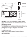
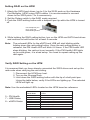
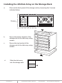
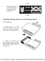
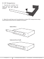
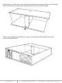
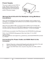
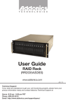
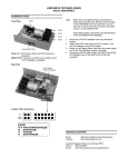
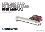
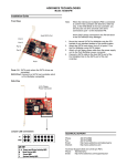
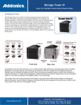
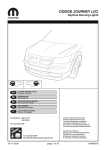
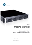
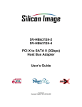
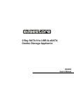
T E C H N O L O G I E S
User Guide
Storage Rack
(SR46S4R5HM)
www.addonics.com
v8.1.11
Technical Support
If you need any assistance to get your unit functioning properly, please have your
product information ready and contact Addonics Technical Support at:
Hours: 8:30 am - 6:00 pm PST
Phone: 408-453-6212
Email: http://www.addonics.com/support/query/
I
O
Front
Power Switch
POWER
System Reset
RESET
Buzzer Reset
Back
Buzzer
Punch out for USIB connectors
Fans
POWER
LED Display
FAN
I
O
I
O
TEMP
Punch out for USIB connectors
Power Supply
HDD
Punch out for eSATA
Punch out for port multipliers/bridges
Power Switch: This is the switch to power on devices connected to the power
supply. The power LED will light up to indicate power is supplied.
Note: The main power switch located at the back of the enclosure must be turned
on first.
Reset Button: Not operational.
Buzzer Reset: Pressing the button stops the overheat buzzer from making a sound.
The buzzer will make a sound when temperature inside the storage rack exceeds the
temperature setting on the Thermal Management card.
Note: Buzzer reset switch does not silence the port multiplier buzzer.
Power LED: Lights up when the power switch is turned on.
Temp LED: Lights up when temperature setting inside the storage rack exceeds
the setting on the thermal card.
Fan LED: Normally on when fan is operational. If an abnormal condition is
detected, the LED flashes.
HDD LED: Not operational.
www.addonics.com
Technical Support (M-F 8:30am - 6:00pm PST)
Phone: 408-453-6212
Email: www.addonics.com/support/query/
I
O
I
O
Top Cover Screws
O
3.
I
2.
Locate the 2 screws at the back of the
storage rack
Turn screws counterclockwise to
loosen.
Lift the top cover and pull towards the
rear end of the rack.
O
1.
I
How to Remove the Top Cover:
3.
O
I
2.
Align the top cover with the edges of
the rack.
Lay it flat on the rack and slide it
towards the front of the rack.
Turn screws clockwise to tighten.
O
1.
I
To Mount Back the Top Cover:
Lift the chassis up.
www.addonics.com
Technical Support (M-F 8:30am - 6:00pm PST)
O
3.
I
Locate the 4 screws on the drive cage.
Turn screws counterclockwise to
loosen.
O
1.
2.
I
How to Remove the 5 ¼” Drive
Cage:
Phone: 408-453-6212
Email: www.addonics.com/support/query/
How to Remove the 5 ¼”
Drive Bay Front Panels:
1.
2.
3.
Locate the 3 screws for each
front panel.
Turn screws
counterclockwise to loosen.
Pull the front panel forward,
away from the drive cage. 3 screws for each panel
Thermal Management Card on the RAID Rack
Fan Connectors
Overheat Buzzer
Floppy Power Connector
Ambient Detect Terminal
Temp. Setting
(40°C, 50°C, 60°C)
Fan, Temperature and Power LED Connectors
Fan Detect Selection
Features
Fan1 to Fan8 could be set either “ENABLE” or “DISABLE”. When all the fans are set
on “DISABLE”, the Fan LED will have no light on.
When Ambient temperature (or temperature inside the storage rack) is over the set
temperature, the LED will flash and the buzzer will sound.
www.addonics.com
Technical Support (M-F 8:30am - 6:00pm PST)
Phone: 408-453-6212
Email: www.addonics.com/support/query/
4x1 Hardware Port Multiplier (AD4SR5HPMU-E)
RAID config rotary switch
USB port connection
to any USB controller
RAID setting button
eSATA Port
PM Health LED
eSATA LED
USB LED
SATA
Port 4
SATA
Port 1
Pin 1
SATA
Port 2
USB 5-Pin Header
Pin 1
LED pins
SATA
Port 3
Rotary Switch
USB 5-Pin Header Pin Assignment
LED Pin Assignment
LED Status
Drive Activity LED: Always ON. The LED blinks when there is drive activity.
PM Health: Always OFF when RAID volume is working correctly. The LED starts
blinking when the RAID volume is degraded.
PM Power: Always ON when power is provided to the HPM.
USB Status: ON when USB port is connected.
eSATA Status: ON when eSATA port is connected.
Instruction for Special RAID Modes
BIG 2 - 2 Drives Spanned
o
Note: Do not connect more than 2 SATA drives to the hardware port
multiplier. Doing so will hang the system when you configure the raid.
o
For SATA drives with different capacities, the hardware port multiplier will
use the smallest drive capacity of the 2 drives connected to create the total
partition size.
FAST 2 - 2 Drives Striped
Note: Do not connect more than 2 SATA drives to the hardware port multiplier.
Doing so will hang the system when you configure the raid.
www.addonics.com
Technical Support (M-F 8:30am - 6:00pm PST)
Phone: 408-453-6212
Email: www.addonics.com/support/query/
Setting RAID on the HPM
1. Attach the SATA hard drives (up to 4) to the SATA ports on the Hardware
Port Multiplier (HPM) using SATA cables. It is recommended to connect
drives to the SATA ports 1 to 4 successively.
2. Set the Rotary switch to the RAID mode required.
3. Push the RAID setting button with a ballpoint pen tip while the HPM is turned
off.
Use a ballpoint pen
tip to press the
RAID Setting Button
4. While holding the RAID setting button, turn on the HPM and SATA hard drives
and continue to hold button for at least 5 seconds.
Note:
The onboard LEDs for the eSATA and USB will start blinking while
holding down the raid setting button. Once the raid setting button is
released, the PM Health LED will blink 4-6 times. If the PM Health LED
stops blinking, the raid set is set correctly. If the PM Health LED lights
up as solid green, it is a bad setup. You need to repeat setting up the
raid again.
Verify RAID Setting on the HPM
It is assumed that you have already connected the SATA drives and set up the
raid mode when verifying the raid setting.
1. Disconnect the HPM from host.
2. Turn on the Storage Rack.
3. Hold down the RAID setting button with the tip of a ball point pen.
Using the table below, verify if the LEDs are lighting up. The selected
LEDs will light up.
Note: Use the embedded LED’s located on the HPM board as reference
5 – PM Health
7 – USB Status
8 – eSATA Status
www.addonics.com
RAID Mode
LEDs
BIG 2
BIG 4
FAST 2
FAST 4
SAFE FAST
SAFE 2
RAID 3 + S
RAID 5 + S
LEDs 5, 7 & 8 all OFF
5 ON, 7 & 8 OFF
7 ON, 5 & 8 OFF
8 ON, 5 & 7 OFF
5 & 7 ON, 8 OFF
5 & 8 ON, 7 OFF
7 & 8 ON, 5 OFF
5, 7 & 8 all ON
Technical Support (M-F 8:30am - 6:00pm PST)
Phone: 408-453-6212
Email: www.addonics.com/support/query/
Installing the 4th Disk Array on the Storage Rack
a.
Remove the back panel of the storage rack by loosening the 4 screws
indicated below.
I
O
I
O
Screws
b.
Secure the bottom bracket of the
storage rack to the disk array using
screws.
c.
Secure the top bracket of the
storage rack to the disk array using
screws.
R
d.
Slide the disk array
into the storage rack.
www.addonics.com
Technical Support (M-F 8:30am - 6:00pm PST)
Phone: 408-453-6212
Email: www.addonics.com/support/query/
Screws
Secure the Disk array
by screwing the top
and bottom brackets
to the frame of the
storage rack.
I
O
R
I
O
e.
Screws
Installing Storage Devices on the Storage Rack
A. 3.5” hard drive
1. Attach the 3.5” to 5.25”
mounting brackets onto both
sides of the 3.5” SATA or IDE hard
drive using the included screws.
2. Attach the ventilation front
panel and base onto one side of
the mounting bracket using the
black screws included with the
Storage Rack.
www.addonics.com
Technical Support (M-F 8:30am - 6:00pm PST)
Phone: 408-453-6212
Email: www.addonics.com/support/query/
B. 5.25” Storage devices
1. Separate the ventilation front
panel and the metal base by
removing the two flat-head
screws.
2. Attach the metal base onto the optical drive or other 5.25” storage device using
the flat head screws from the ventilation front panel.
Optical Drive
Addonics Drive Cradle
www.addonics.com
Technical Support (M-F 8:30am - 6:00pm PST)
Phone: 408-453-6212
Email: www.addonics.com/support/query/
C. 3.5” Mobile Rack
1. Separate the ventilation front panel
and the metal base by removing the two
flat-head screws.
2.
Attach the 3.5” drive cradle onto
the 3.5” to 5.25” drive bay mounting
bracket at the six aligned screw hole
locations.
3.
Attach the metal base onto the
optical drive or other 5.25” storage device
using the flat head screws from the
ventilation front panel.
With the storage device connected, slide
the metal base back into the drive cage.
Secure the storage device onto the top of
the drive cage using the included screws.
www.addonics.com
Technical Support (M-F 8:30am - 6:00pm PST)
Phone: 408-453-6212
Email: www.addonics.com/support/query/
At the bottom of the drive cage, locate the metal base corresponding to the storage
device inserted in the previous step and secure it onto the drive cage.
O
I
O
I
When you finished, install the drive cage now populated with the devices back
into the Storage Rack.
www.addonics.com
Technical Support (M-F 8:30am - 6:00pm PST)
Phone: 408-453-6212
Email: www.addonics.com/support/query/
Installing Additional Bridge Boards on Mounting Poles
Inside the Storage Rack
Separate PM or HPM from bracket by unscrewing 4 screws on the PCB. Install
the PM or HPM onto the desired mounting pole.
Installing Bridge Boards onto Back Panel
I
O
I
O
Remove punch outs from the rear panel of the Storage Rack. Using the included
screws, attach bridge board onto the desired back panel mounting location.
Connect storage devices onto the internally mounted PM or HPM, then connect
the host connection onto the rear mounted bridge board.
SATA Device
www.addonics.com
PM/HPM
Technical Support (M-F 8:30am - 6:00pm PST)
Bridge Board
Phone: 408-453-6212
Email: www.addonics.com/support/query/
Power Supply
O
I
This power supply provides 500W of
power. Before turning on the main
switch located on the front panel of
the storage rack, turn on the power
switch of the power supply.
Power Switch
Fan
Storage Rack DA with Port Multiplier Using Multilane
Connection
Note: The Port Multiplier will only work with Port Multiplier aware multilane host
controllers. It is compatible with multilane host controllers using the Silicon Image
Chip SiI3124 & SiI3132.
When the port multiplier (PM) is connected to the multilane host controller with
SiI3124 or SiI3132 chip, in the RAID BIOS of the host controller, you will only see
one drive and that is the drive connected to SATA port 1 on the Port Multiplier.
All SATA drives connected to the PM will show in the SATARAID5 Array Manager.
Refer to the SATARAID5 Management Utility User Guide V1.6 for RAID
implementation
http://www.addonics.com/support/user_guides/host_controller/SATARAID5-UserGuid
e_v1.60.pdf
Connecting the Power Cable and RAID Rack to the
Computer
a.
b.
c.
Connect the power cord provided from the wall outlet to the back of the rack.
Make sure the power is off (power LED light should be off).
Connect the RAID Rack to the computer using either the USB or eSATA
cable.
www.addonics.com
Technical Support (M-F 8:30am - 6:00pm PST)
Phone: 408-453-6212
Email: www.addonics.com/support/query/
CONTACT US
www.addonics.com
Phone:
Fax:
Email:
408-573-8580
408-573-8588
http://www.addonics.com/sales/query/