1
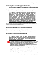
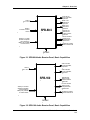
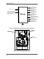
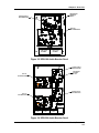
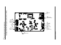
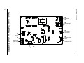
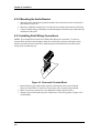
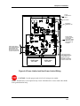
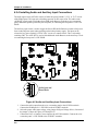
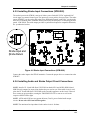
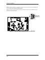
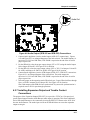
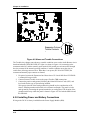
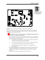
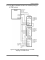
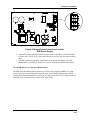
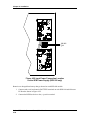
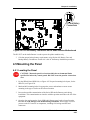
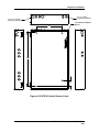
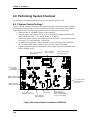
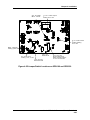
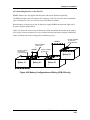
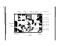
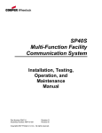
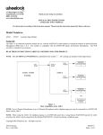
Chapter 4: Installation
Audio Out
Figure 4-8 Audio Output (SPB-160 and SPB-320) Connections
1. Connect Audio Appliance circuit to Audio Output (AUD OUT) connection(s). Figures
4-12 and Figure 4-13 are enlarged diagrams of the referred areas. The Audio Output(s) is
supervised. A UL Listed 10K Ohm, 1/2W EOLR is required at the end of the circuit for
proper supervision.
2. For the SPB-80/4, select the proper output voltage (25V or 70V) using the Audio Output
Select Jumper J1B and J3. See Figure 4-25 for location.
3. For the SPB-160, select the proper output voltage (25V or 70V). Use Jumpers J1A and J3
for AUD1 and Jumpers J1 and J2 for AUD2. See Figure 4-26 for location.
4. Connect Strobe Appliance circuit to STB Outputs (STB1 OUT, STB2 OUT) connections.
Figure 4-12 is an enlarged diagram of the referred area. The strobe outputs are
supervised. A UL Listed 10K Ohm, 1/2W EOLR is required at the end of the circuit for
proper supervision.
5. Select the proper strobe-operating mode (Wheelock sync, Cooper Wheelock Pass through
Sync, or 24VDC constant), Select Jumper JP5. See Figure 4-25 for location.
Note: Both outputs of the SPB-80/4 are synchronized. If system wide synchronization is
required, remove JP5 for pass-through operations.
4.2.7 Installing Expansion Output and Trouble Contact
Connections
The purpose of the Expansion Output (EXP OUT) is to provide a 27VDC at 0.5A supervised,
power-limited output when the Audio Booster audio output is operating. This allows additional
Series SPB Audio Boosters to be connected by having the EXP OUT connect to the AUX IN of
the next Audio Booster. The strobe input circuit on an SPB-80/4 does not cause the expansion
output to energize.
Series SPB Audio Boosters Manual, Revision A
4-11