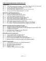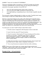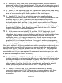
1
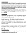
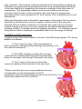
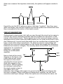
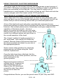
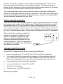
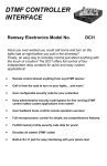
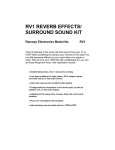
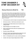
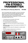
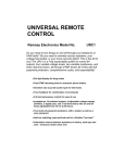
ELECTROCARDIOGRAM HEART MONITOR KIT Ramsey Electronics Model No. ECG1 An educational kit to apply the principles of differential amplifiers while monitoring your heart rhythm! Actually monitors your heart rhythm and displays it with a flashing light! A must for the budding intern, with ultra safe low voltage operation. Easy Oscilloscope hookup to give a true EKG display! Have some fun with this truly unique kit ! • Visible and audible display of your heart rhythm ! • Learn about what makes your heart beat , and how we monitor the heart rhythm! • Examine and use differential amplifiers and learn about how they are used ! • Re-usable sensors included, just like visiting the lab in your health care facility ! • Adjustable gain and volume controls. • Super safe 9VDC operation, high impedance input . • Check your resting heartbeat, monitor your heart health. • Add our matching case and knob set for a professional appearance ECG1 • 1 RAMSEY TRANSMITTER KITS • FM100B Professional FM Stereo Transmitter • FM25B Synthesized Stereo FM Transmitter • MR6 Model Rocket Tracking Transmitter • TV6 Television Transmitter RAMSEY RECEIVER KITS • FR1 FM Broadcast Receiver • AR1 Aircraft Band Receiver • SR2 Shortwave Receiver • SC1 Shortwave Converter RAMSEY HOBBY KITS • SG7 Personal Speed Radar • SS70A Speech Scrambler • BS1 “Bullshooter” Digital Voice Storage Unit • AVS10 Automatic Sequential Video Switcher • WCT20 Cable Wizard Cable Tracer • LABC1 Lead Acid Battery Charger • LC1 Inductance-Capacitance Meter RAMSEY AMATEUR RADIO KITS • DDF1 Doppler Direction Finder • HR Series HF All Mode Receivers • QRP Series HF CW Transmitters • CW700 Micro Memory CW Keyer • CPO3 Code Practice Oscillator • QRP Power Amplifiers RAMSEY MINI-KITS Many other kits are available for hobby, school, Scouts and just plain FUN. New kits are always under development. Write or call for our free Ramsey catalog. ECG1 KIT INSTRUCTION MANUAL Ramsey Electronics publication No. MECG1 Rev 1.1 First printing: August 2001 COPYRIGHT 2001 by Ramsey Electronics, Inc. 590 Fishers Station Drive, Victor, New York 14564. All rights reserved. No portion of this publication may be copied or duplicated without the written permission of Ramsey Electronics, Inc. Printed in the United States of America. ECG1 • 2 Ramsey Publication No. MECG1 Price $5.00 KIT ASSEMBLY AND INSTRUCTION MANUAL FOR ELECTOCARDIOGRAM HEART MONITOR KIT TABLE OF CONTENTS Introduction ................................. 4 Circuit Description....................... 7 Schematic Diagram .................... 9 Parts Layout Diagram ................. 10 Parts List .................................... 11 Assembly Instructions ................. 13 Using your ECG1 ........................ 20 Troubleshooting Guide ............... 21 Warranty ..................................... 23 RAMSEY ELECTRONICS, INC. 590 Fishers Station Drive Victor, New York 14564 Phone (585) 924-4560 Fax (585) 924-4555 www.ramseykits.com ECG1 • 3 IMPORTANT NOTE: This Ramsey Electronics kit is NOT intended for any medical usage. It is simply for experimenters and hobbyists who wish to observe an EKG waveform using common components and commercially available sensors. Every reasonable precaution was used in the design and manufacture of this product to make it an accurate monitor, but you cannot draw any conclusions from the results (you may, however, astound your physician with your knowledge of EKG operation). Please leave any diagnosis of illness based on the analysis of EKG’s to health care professionals using certified equipment. Also, we realize that our customers are experimenters and on occasion have modified our kits to suit their individual needs. PLEASE DO NOT MODIFY THIS KIT IN ANY WAY as you will be hooking electrodes to the human body to monitor the EKG waveform. DO NOT EVER use a battery eliminator connected to 110 vac power. INTRODUCTION It has been said “What a piece of work is man”. The complexities of the human body and our biological systems exceed the most complex machines that we can produce. Our nervous system and synaptic processes are still not fully understood by the most clever scientists. Consider the heart muscle. This delicate and complex bit of tissue can be likened to a simple pump. Now if we take the averages, this pump moves roughly two and one-half ounces of liquid per heartbeat. If we assume an average heart rate of 72 beats in a minute, our heart muscle moves over a gallon per minute, about 1900 gallons a day, over 700,000 gallons per year. If we carry this out over a lifetime, by the time we reach seventy years of age our heart has pumped over 45 million gallons! Not bad for a half pound pump that is the size of your fist! Another fascinating feature of the heart muscle is its ability to continue to beat automatically, day in and day out, for our entire life. The heart contains a built in pacemaker that regulates the rhythm of the muscle. This can be adjusted by the rest of our nervous system. All these nerves “firing” cause an electrical output that we can actually measure. That is what brought about our Ramsey ECG1 kit. Ramsey Anatomy 101: Let’s take a closer look at the heart muscle and its operation. The heart muscle contains four individual chambers, with left and right atriums and ventricles that contract when pushing blood throughout the body. ECG1 • 4 This filling and pushing action is accomplished using specialized one way valves. There are four of these valves, one for each chamber. These valves allow the blood to exit when the chamber contracts, then close to allow the chamber to fill with fresh blood for the next beat. The right side of the heart is devoted to pumping the oxygen depleted blood to the lungs. After the lungs have oxygenated the blood it is returned to the left side of the heart where it is pumped throughout the body. Left atrium Pulmonary valve Aortic valve Mitral valve Left ventricle Right atrium Tricuspid valve Right ventricle Setting the “Pace” As long ago as 1855, researchers Kollicker and Mueller discovered that when a motor nerve from a frog’s leg was laid over its beating heart, the leg would kick with a regular beat. In 1901 this research lead Dr. Willem Einthoven to create a simple machine that could observe and record the electric impulses created in the heart muscle. The invention was called an electrokardiogram, or EKG (note that the modern English spelling is electrocardiogram or ECG. These names are commonly interchanged). Einthoven noted the characteristic waveform created by the heart had specific regularities which he defined as the P, QRS, and T waves (more about this later). Our modern research has more clearly defined the electrical operation that takes place with each beat. The Sinoatrial (SA) node, located in the right atrium sets the natural pace of the heart rhythm. This nerve causes both atria to contract together, depolarizing the charge in the cells, while filling both ventricles with blood. The electrical impulse has now traveled to the Atrioventricular node (AV), then through the bundle of His, where it branches to both the left and ECG1 • 5 right ventricles. The impulse continues through the Purkinje fibers causing the ventricles to contract and squeezing the blood on its way throughout the body. In the time that this is happening, the atria are resetting for the next beat, or repolarizing. The polarization effect on the muscle cells is due to ionicmolecular level function of the individual cells, and the ionic compounds (including sodium (Na), potassium (K), and calcium (Ca)) contained in the cells themselves. While the Sinoatrial node is the built in pacemaker of the heart, this too can be adjusted by the autonomic nervous system, which reacts to the everyday stresses that we subject ourselves to. Consider the range we put our heart muscle through every day, from rest (sleeping), through moderated activity (walking, talking), to aerobic workouts (jogging, bicycling). It is certainly a good thing that we have a feedback mechanism wired in for our range of activity. The EKG (or ECG) waveform: A typical cycle of the heart rhythm is shown in the following diagram. The timing pattern is a follows: 1) The P wave is seen. This corresponds to both the atrium contracting (depolarizing) and priming the ventricle with blood. P Wave 2) The QRS complex is where the stronger ventricles fire, pushing blood through the pulmonary artery to the lungs, and through the aorta to the body. 3) The T wave is the time at which the ventricles repolarize themselves for the next beat . *Please note that there are many additional sources of information on the interpretation of ECG waveforms; visit your local library or search the World Wide Web (search for ECG or EKG). ECG1 • 6 QRS & T Wave When we measure the impulses electrically, the pattern will appear similar to this: QRS T P Atrial Ventricular Depolarization Depolarization Ventricular Repolarization Hopefully now the ECG patterns seem a little less “mystical ” than they were when we began, and we have cleared up how the pulses are created and how they correspond to the action of the heart muscle. CIRCUIT DESCRIPTION Getting back to electronics, let’s talk our way through the circuit we’re using to monitor the minute electrical impulses that are present due the action of the nerves of the heart muscle. These signals are in the microvolt range, and are swamped out by other noise and static present on our body at any time (if you don’t believe me, try and touch the probe tip of an oscilloscope sometime and have a look at the output waveform). So what we need is a circuit that will eliminate any common noise present on the inputs and amplify the difference between two common voltages. The circuitry used on the ECG1 is a common application for operational amplifiers, or op-amps, known as a differential amplifier. Have a look at the circuit diagram in the figure, and notice that we are using two inputs to the circuit, and that the circuit mirrors itself with respect to the two inputs. Without getting too involved, notice that the single ended output is only taken off of one transistor; this voltage with respect to ground is the difference between the two input voltages. When both inputs change level together, we call that a common mode input change. When the inputs are not exactly the same, we ECG1 • 7 call the differential change a normal mode. A well designed differential amplifier has a large common mode rejection level (CMRR), or the ratio of response for the normal mode to the response of the common mode signal of the same level. The differential circuit is used extensively in modern electronics circuits. There is a great amount of common noise present on most long runs of wire (telephone transmission, theater audio, computer networking, etc.), and the differential amplifier can be used to recover the original signal provided that the common mode signals are not too large. Take a look at the circuit schematic for the ECG1 kit and follow the two inputs. Notice first that the input voltages are capacitively coupled to the circuit, with extremely high resistances following the capacitors. [Note that at no time should you EVER attempt to run a current through the skin in the vicinity of your heart]. Notice that they are both tied to differential inputs of the LM324 op amp. Resistor R5 acts as a gain control for the differential voltage with a range of about 100 to almost 10,000, ideally suited for the bioelectric potentials we are attempting to measure. Since the action of the nerves in the heart muscle are relatively slow (on the order of milliseconds), we can incorporate several “low pass” filters to eliminate any high frequency noise that may be present on our signal as well. You’ll notice a few R-C combinations (R8 and C7, R9 and C8, R10 and C9) that effectively filter off any high frequency noise that is present on the signal leaving our “thump-thump” heartbeat signal intact for analysis. Our output signal is coupled to the indicator light (led D2) that is triggered whenever transistor Q1 is turned on by a positive peak. We have also included an audio amplifier (U2) to provide gain for a small speaker or headphone output. The monitor output provides a convenient connection for an oscilloscope to view the EKG pattern directly. Our circuit runs directly using an alkaline 9V battery, keeping us away from any nasty ground loops or potential differences that could affect the performance of the kit. This also limits the possibility of bodily harm through the improper use of an external power supply. ECG1 • 8 ECG1 SCHEMATIC DIAGRAM ECG1 • 9 ECG1 PARTS PLACEMENT DIAGRAM ECG1 • 10 PARTS SUPPLIED WITH YOUR ECG1 KIT Capacitors 7 .1 µF disc capacitor (marked .1 or 104 or 100 nF) [C1,2,6,7,8,9,18] 1 470 pF disc capacitor (marked 470 or 471) [C5] 1 1 µF electrolytic capacitors [C4] 7 10 µF electrolytic capacitors [C3,10,12,13,14,16,17] 3 100 µF electrolytic capacitors [C11,15,19] Resistors and Potentiometers 1 2 ohm (red-black-gold) [R16] 1 470 ohm (yellow-violet-brown) [R17] 1 4.7K ohm (yellow-violet-red) [R11] 3 10K ohms (brown-black-orange) [R3,4,13] 1 47K ohms (yellow-violet-orange) [R15] 5 100K ohms (brown-black-yellow) [R7,8,9,10,12] 3 10M ohms (brown-black-blue) [R1,2,6] 1 PC mount 10K ohm potentiometer (marked 103) [R14] 1 PC mount 100K ohm potentiometer (marked 104) [R5] Semiconductors and Integrated Circuits 1 1N4148 diodes (small glass diode) [D1] 1 2N3904 transistor (three leads TO-92 package marked 3904) [Q1] 1 JUMBO red LED [D2] 1 LM 324 Quad Op-Amp (14 pin DIP) [U1] 1 LM 386 IC (8 pin DIP) [U2] Miscellaneous Components 2 3.5mm stereo jack (5 leads) [J1-2] 1 3.5mm mono jack (3 leads) [J3] 1 DPDT PC mount pushbutton switch [S1] 1 9 Volt rectangular battery clip with leads [BAT1] 1 Battery holder mounting bracket (silver steel bracket) Probe Components 1 3.5mm stereo plug (for use with probe wires) 3’ #24 AWG black hookup wire 6’ #24 AWG red hookup wire 3 Alligator clips 1 Sheet of 10 ECG Electrode Tabs ECG1 • 11 RAMSEY "Learn-As-You-Build KIT ASSEMBLY There are numerous solder connections on the ECG1 printed circuit board. Therefore, PLEASE take us seriously when we say that good soldering is essential to the proper operation of your EKG kit! • • • Use a 25-watt soldering pencil with a clean, sharp tip. Use only rosin-core solder intended for electronics use. Use bright lighting; a magnifying lamp or bench-style magnifier may be helpful. Do your work in stages, taking breaks to check your work. Carefully brush away wire cuttings so they don't lodge between solder connections. We have a two-fold strategy for the order of the following kit assembly steps. First, we install parts in physical relationship to each other, so there's minimal chance of inserting wires into wrong holes. Second, whenever possible, we install in an order that fits our "Learn-As-You Build" Kit building philosophy. This entails describing the circuit that you are building, instead of just blindly installing components. We hope that this will not only make assembly of our kits easier, but help you to understand the circuit you’re constructing. For each part, our word "Install" always means these steps: 1. Pick the correct component with the proper value to start with. 2. Insert it into the correct PC board location. 3. Orient it correctly, following the PC board drawing and the written directions for all parts - especially when there's a right way and a wrong way to solder it in. (Diode bands, electrolytic capacitor polarity, transistor shapes, dotted or notched ends of IC's, and so forth.) 4. Solder all connections unless directed otherwise. Use enough heat and solder flow for clean, shiny, completed connections. 5. Trim or nip the excess component lead wire after soldering. NOTE: Save some of the longer wire scraps nipped from resistors and capacitors. These will be used to form wire jumpers (JMP1, etc.) to be soldered in just like parts during these construction steps. Enough of that ... let’s get started! ECG1 • 12 ECG1 ELECTROCARDIOGRAM KIT ASSEMBLY Although we know that you are anxious to complete the assembly of your electrocardiogram kit it is best to follow the step-by-step instructions in this manual. Try to avoid the urge to jump ahead installing components. Since you may appreciate some warm-up soldering practice as well as a chance to put some landmarks on the PC board, we’ll first install some of the larger mounting components. This will also help us to get acquainted with the up-down, left-right orientation of the circuit board. Remember that the majority of the components will be mounted on the component side of the circuit board and soldered on the solder side of the circuit board, the side that contains the printed circuit traces. Have a look at the parts layout diagram to help with your assembly. Use the boxes to check off your progress. Check all received parts against the parts list. The parts list describes the various markings that may be found on the kit parts. Carefully sort the parts into small piles, (an empty egg tray does nicely for this purpose) to aid in finding the correct part at the required time. Although not necessary, you may install an IC socket in the U1 position. Today's IC’s have achieved remarkable performance levels and it is extremely unlikely that any of your chips will have problems, yet we know that some of our hobbyists insist on socketing all IC components. The addition of these will not “void” your warranty, but if a problem arises from a socketed component you will be required to pay the additional technician fee for labor in the repair of your kit, if necessary. Now we will install the input and output connectors of the circuit. We use several printed circuit (PC) type jacks to accomplish our interfaces. These jacks typically have several mounting pins associated with each connector. Notice on the schematic how these connectors use extra contacts as switches so that when the plug is inserted the contacts will open. That’s how your transistor radio turns off the speaker when you plug in your headphones! 1. Identify and install audio connector J2, 3.5mm stereo, towards the rear of the printed circuit board. Gently slide the leads through the board until the connector is mounted flush, with the connection hole facing towards the outside of the PC board. Solder all the connections using enough heat to flow the ground connection completely. This may take a little while depending on the wattage of your soldering pencil. Use caution when soldering the other leads so that too much time or heat is not applied; it may cause the printed circuit trace to lift away from the circuit board. ECG1 • 13 2. Identify J3, the 3.5mm mono jack. Again, slide this through the circuit board and solder all three leads securely. This jack will act a monitor output port for your kit, providing a convenient hookup for an oscilloscope to give a visual display of an EKG waveform. 3. Install J1, the last stereo type jack. Careful with those leads; make sure that they all make it through the board before you solder them into place. J1 acts as the connection point for the probes to the circuit inputs. 4. Identify C19, the 100 uF electrolytic capacitor (small cylindrical component coated with plastic and marked 100). Electrolytic capacitors are polarized with a (+) and (-) lead and must be installed in the correct orientation. Ordinarily, only the negative side is marked on the capacitor body with a dark band and the (-) sign clearly shown, while the PC boards will usually show the (+) hole location. Use care to ensure proper polarity. See the parts diagram for proper placement. The capacitor should fit snugly down to the PC board. Save those long leads that you trim off to fashion jumper connections later in the assembly. 5. In the same manner, install C15, another 100 uF electrolytic (small cylindrical component coated with plastic and marked 100). Electrolytic capacitors store a large amount of charge and keep the supply voltage from “sagging” when a large current is momentarily required. Notice on the schematic how C15 is used in this manner; the cap stores energy so that when the “thump” of the EKG signal is sent to the headphone, the audio amplifier (U2) is not starved for power. Use care to ensure proper polarity. See the parts diagram for proper placement. The capacitor should fit snugly down to the PC board. Now we’re getting to it! Have a look at your solder connections and retouch any less than perfect ones. We will continue our assembly with the audio amplifier section of the circuit, using the versatile LM386 audio amp IC. This integrated circuit is one of the standards in today's electronic industry so don’t be surprised to see it if you open a piece of commercial electronics gear (one with a speaker or headphone output, of course). 6. Install U2, the LM386 Audio Amplifier 8 pin IC (marked 386). Make sure to align the notch or dot associated with pin one with the notch shown in the parts layout diagram. It may be helpful to gently “rock” the IC on its side on a hard flat surface before installing to align the rows of pins so that they slide in easily. Don’t be afraid to use enough solder and heat for a good solder connection, and be extra careful not to “bridge” any solder connections together. 7. Install C14, one of the 10 uF electrolytic capacitors (in a small cylindrical case marked 10 uF). Remember to observe polarity with those electrolytic capacitors! Check the parts placement diagram for correct orientation. ECG1 • 14 8. Install R16, 2 ohms (red-black-gold). 9. Install C18, .1 µF disc capacitor (marked 104 or .1). Disc capacitors are not polarized; they can be installed in either direction. The reason we call them “disc” caps can be seen in the package. The capacitor itself is two conductive discs separated by a dielectric compound. Take a moment now to check your previous solder joints for “opens” where the solder did not completely flow around the connection, or solder bridges between closely spaced pads or IC pins. It seems the best time to identify these types of problems is now when you’re focused on this section of the board, saving you time to try to retrace your steps later. 10. Install C13, 10 uF electrolytic capacitors (in a small cylindrical case marked 10 uF). Check the parts placement diagram for correct orientation. Watch that polarity! 11. Using a scrap component lead, form a jumper wire and install in the JMP3 holes. Jumpers act like electronic “bridges” that carry power or signals over active traces on the circuit trace side of the board. Solder both ends of the jumper into place. 12. Install C3, 10 uF electrolytic capacitor (in a small cylindrical case marked 10 uF). Check the parts placement diagram for correct orientation. 13. Install R13, 10k ohms (brown-black-orange). Next we will move on to the amplifier section of the kit, constructing the differential amplifier and associated circuitry. We will continue from the rear of the circuit board and work our way forward. Remember to keep the lead lengths as short as possible (to avoid any noise being introduced in the circuit). Also, keep a few more of those scrap leads handy as we will need a few more jumper wires later. 14. Install C1 and C2, both .1 µF disc capacitor (marked 104 or .1). 15. Install R1 and R2, both 10 M ohms (brown-black-blue). 10 meg, that’s 10 million ohms! 16. Install R3 and R4, 10 k ohms (brown-black-orange). These resistors form a “voltage divider” that sets the input voltage for our op-amp inputs. 17. Install U1, the LM324 Quad Op-Amp 14 pin IC (marked 324). Make sure to align the notch or dot associated with pin one with the notch shown in the parts layout diagram. It may be helpful to gently “rock” the IC on its side on a hard flat surface before installing to align the rows of pins so that they slide in easily. Don’t be afraid to use enough solder and heat for a good solder connection, and be extra careful not to “bridge” any solder connections together. ECG1 • 15 18. Install C8, .1 µF disc capacitor (marked 104 or .1). 19. Install R9, 100k ohms (brown-black-yellow). 20. Install R12 and R10, both 100k ohms (brown-black yellow). 21. Identify C11, 100 uF electrolytic capacitor (small cylindrical component coated with plastic and marked 100uF). Electrolytic capacitors are polarized with a (+) and (-) lead and must be installed in the correct orientation. Use care to ensure proper polarity. See the parts diagram for proper placement. The capacitor should fit snugly down to the PC board. 22. Install C6 and C7, both .1 uF disc capacitors (marked .1 or 104). 23. Install R8, 100k ohms (brown-black-yellow). 24. Install C9, .1 uF (marked .1 or 104). Have you figured out what that 104 value stands for yet? Here’s the answer. Disc capacitors are typically marked in their value in picofarads, or pF (pronounced “puff”), equal to a value of 1x10-12 Farad. A 104, or 100,000 pF disc cap has an equivalent value of 0.1 microfarad or 0.1 uF. Mathematically speaking, 100,000 x 10-12 = 0.1 x10⁻⁶. That’s how we switch between the 104 and .1 values so easily. 25. Install R11, 4.7k ohms (yellow-violet-red). 26. Install C10,C12, and C16, all 10 uF electrolytics (in a small cylindrical case marked 10 uF). Check the parts placement diagram for correct orientation. Careful here, they do not all face in the same direction! 27. Install R15, 47k ohms (yellow-violet-orange). 28. Install C5, 470 pF disc capacitor (marked 470 or 471). 29. Install R6, 10M ohms (brown-black-blue). 30. Install R7, 100k ohms (brown-black-yellow). 31. Install C4, 1 uF electrolytic capacitor (in a small cylindrical case marked 1 uF). Check the parts placement diagram for correct orientation. Whew! That was some work. But we’re almost done, so now is a good time to recheck all your work up to this point. Carefully inspect the circuit board for stray leads or open solder connections, trim and touch up any that need work. 32. Identify and install D1, the 1N4148 small signal diode (small glass case with a black band). Remember that diodes are polarized, so face the banded end as shown in the parts layout diagram. This is one of the more fragile parts we’ll install; use caution so as not to flex the leads of the device at the junction of the lead wire and the glass case. Solder in place and remove any excess lead. 33. Identify and install transistor Q1, the three leaded component marked 2N3904. The flat side must be placed as shown on the PC board for proper ECG1 • 16 operation. Mount it as close to the board as possible without forcing it. Carefully solder all three leads 34. Using a scrap component lead, form a jumper wire and install in the JMP2 holes. 35. Install R17, 470 ohms (yellow-violet-brown). Next we will install the LED beat indicator for the display. (L)ight (E)mitting (D) iodes are just that, a diode junction that emits light of a particular wavelength when forward biased. Pay close attention to the polarity of the diode as shown in the parts layout diagram. 36. Install LED D2. The flat side is oriented as shown in the diagram. Leave it standing about 3/4 of an inch off of the board when soldering. After soldering bend it over to a 90º angle at its midpoint so that it faces the outside of the board. Observe the following diagrams for proper orientation. LED Flat Leave leads approximately 3/4 inch in length LED PC Board Front View Flat Leave leads approximately 3/4 inch in length PC Board Front View after Bending 37. Identify the battery holder clip. Notice that there are two holes punched through the metal. Fashion a small jumper wire to fit through the holes and solder securely on the solder side of the circuit board. This will hold the battery “holder” in place. 38. Locate the 9 volt battery snap included with your kit. Install the black and red wire as shown in the parts placement diagram. Almost there! Pretty soon you will be monitoring your heart’s electrical impulses. Even though you can hardly wait to fire up the kit, take a few minutes to recheck your assembly up to now. Touch up any solder connections, recheck electrolytic/diode/transistor orientations. A few minutes now can save time tenfold once you have energized the circuit, since incorrectly installed parts can be damaged once power is applied. 39. Install pushbutton switch S1 by inserting all six leads through the circuit board. The switch should fit flat to the circuit board before soldering. 40. Identify the 10k PC mount potentiometer (labeled 103) and install it in the R14 position. 41. Identify the 100k PC mount potentiometer (labeled 104) and install it in the R5 position. Great job! You’ve made it through the circuit board assembly of your ECG kit. Now we will work on the input probe and associated wires. First, here are a ECG1 • 17 couple of pointers. Remember to install the connector cover when requested; it can save time and the aggravation of unsoldering and resoldering the connectors. When soldering to the connectors themselves use enough time and solder to create a robust connection but don’t leave your iron on the connection for an excessive amount of time as it can melt the plastic insulator on the connector itself. It is helpful to hold the connector in place with a small vise to aid in soldering. 42. Identify the stereo plug included with your kit, as well as the lengths of red and black wire. You will need to cut the red wire in half before proceeding any further, so that you have three lengths of wire to work with. Remove the cover from the stereo jack by unscrewing it from the connector. 43. Carefully trim 1/8” of insulation from both ends of each wire, leaving all six ends exposed. Re-twist any frayed ends before proceeding. 44. Carefully insert one of the red wires into the tip (center pin) connection of the stereo plug, solder into place. 45. Repeat this process with the second red wire to the ring connection. Be sure to trim off any excess wire so that the connections will not “short circuit” when the cover is reinstalled. 46. Carefully insert one end of the black wire through the “ground” connection of the stereo jack, and solder into place. Solder Black 47. Inspect all connections and Red Red when you are satisfied that each is acceptable, insert the unconnected end of each of the three wires through the plastic cover. Slide the cover until it reaches the plug, and screw it into place. 48. With the three remaining ends of the wires, solder each to one of the alligator clips provided with your kit. Once soldered you may use small pliers to bend the strain relief tabs of the alligator clips to mechanically hold the wires in place. This will prevent Solder the wires from fracturing when you connect them to the sensor tabs that will be mounted on your skin. 49. Please note that we have not installed either jumper wire JMP1 or C17, a10 uF electrolytic capacitor. Install jumper wire JMP1 if you are using a stereo headphone set to listen to the ECG rhythm. Capacitor C17 will significantly limit the audio output, and may be desired if using a single earpiece speaker when listening. ECG1 • 18 CONGRATULATIONS ! Your ECG monitor is now complete! Have a final look over your work, paying particular attention to the orientation of diodes, capacitors, and IC’s. Remember that any problems you find now can save time and effort after the unit has been cased up. ASSEMBLY INSTRUCTIONS FOR CUSTOM CASE The enclosure is a key element to the overall pride you will have upon completing your Ramsey kit. The enclosure will show how you were able to “build from scratch” a commercial piece of high-tech electronics. For some of us, the enclosure will also hide a number of “not-so-pretty” assembly mistakes. Once the kit is enclosed, your friends will never know that you were new to soldering. Finally, the enclosure case will protect your electronics from many possible causes of damage so that you can receive years worth of enjoyment using, talking about, and remembering the fun you had building your kit. In short, TAKE YOUR TIME when assembling the enclosure. This is the part that you and your friends will look at and admire for years! 1. Lay the front and rear plastic plates over their corresponding labels to verify which sticker goes with which panel. You’ll want to work with one panel at a time to avoid possible mix-ups. 2. Remove the backing material from one of the stickers and line it up properly on its pre-punched panel. Make sure that they are aligned correctly before allowing them to touch the plastic plates. They stick the first time; line them up right! 3. Use a sharp hobby knife to cut out the holes in the labels along the prepunched holes. A short sawing motion works well around the inner circumference of the holes. 4. Repeat the above steps for the other panel. 5. Insert the board into the case with the knobs and LED extending through the holes in the front panel. 6. Raise the rear portion of the PC board and extend the jacks through the rear plastic plate. Insert the plate into the grooves on the base tray. 7. Secure the PC board to the bottom base tray with 4 short Phillips head screws. ECG1 • 19 USING YOUR ECG1 ELECTROCARDIOGRAM Now we’re ready for the moment of truth, the initial power up and running of your ECG1. Be ready to energize the unit by installing a fresh 9 volt battery in place and connected to the snap tab. You may want to install a set of headphones or small speaker to the audio out jack as well. Start with both the volume and gain set to the lowest (rotate CCW) positions. ELECTRODE PLACEMENT FOR OPTIMUM PERFORMANCE There really aren’t too many “wrong ways” to hook up your electrodes, and since we figure you are a full fledged experimenter (you did build this kit!) we realize that you will be tinkering around with your electrode placement. A few of the test books and web sites consulted did recommend some placement positions so these will be included with the text. It was emphasized, however, that multiple placements of electrodes could give insights to the operation of the heart muscle. Just as a picture of a jumbo jet head-on can look quite different than one from an oblique angle, EKG Limb Lead Electrode placement results from different places can give clues to the overall operation of the heart. The “classic” method of probe connection is the “limb leads”, first used by Dr Einthoven himself. Remove three of the sensor tabs from the sheet provided and attach to your skin in the appropriate places. Electrode Electrode Some various other positions for electrode placement are as follows using the “trunk” method of placement. Once the tabs have been attached, clip the red electrodes to the active positions, and the black electrode to the ground position. Ground Electrode Modified Limb Lead Electrode placement Depress the power switch to activate the kit. Increase the gain adjustment until you observe the LED blinking at a repetitive rate, then adjust the volume to hear the pulses. Ground Electrode Ground Electrode Electrode positions 1-6 Ground Electrode Ground Electrode Congratulations Doctor, you are the proud owner of your very own EKG ECG1 • 20 monitor. Feel free to experiment with other electrode positions. One of the favorites around the lab here is the “valley” method. The ground probe is placed on the stomach or wrist and the differential probes placed at the base of the sternum and the other just below the neck line. The newlyweds have also come up with a method of placing a differential probe on each chest while the ground is placed on one wrist, and listening for the two sets of ECG waveforms. A tight embrace is required to “equalize the ground potential” between the love birds. OSCILLOSCOPE HOOKUPS Your ECG kit has been equipped with an output jack exclusively for hookups to connect your monitor to an oscilloscope. Simply fabricate a hookup cable that adapts from a 3.5 mm (miniature) type monaural plug (with the center lead being wired as the signal input) to the connector type of your scope. Set your vertical amplifier on the scope to 0.5 volt/division and set the sweep time to 0.5 to 1 second per division. Now sit back and observe the ECG waveform. This is by far the most fun method of operation, and lends itself well to the current “handheld “ portable scope meters as well as digital scopes. By changing the probe positions you can notice changes in the ECG waveforms and begin to investigate the attributes of the different positions. ECG Monitor TROUBLESHOOTING GUIDE If your ECG1 does not work at all, re-check the following: • correct orientation of U1 and U2 (see PC board layout diagram) • You should be able to measure the voltage on the supply pins of both IC’s. Check for 9 volts at pin 8 of the LM386 and Pin 4 of the LM324. Make sure that the ground connections are soldered securely as well. • correct polarity of all electrolytic capacitors. • correct orientation of diodes D1 and D2 • all solder connections • Jumper wires at all JMP locations. Still having trouble? ECG1 • 21 While we had hoped that it wouldn’t come to this, if you are still having trouble with your ECG, here are a few additional suggestions. Use a methodical, logical troubleshooting technique. Most problems can be solved using common sense. A volt-ohm meter and a clear head are usually all that are needed to correct any problem. Most problems are due to misplaced parts and/or bad solder connections. Working backwards through the assembly steps will often lead you to the problem. Re-visit the extensive theory of operation include in this manual, and try to apply to your specific problem. Have another set of eyes look through your work. Here at the shop we have often run into a “stone wall” of a problem only to have a fellow technician see our obvious error. It is sometimes very difficult to see your own mistake; taking a break can often solve this common problem. Also, make sure that you have “checked” all the assembly steps boxes. You may have forgotten one or two of them. Please understand that it is nearly impossible to “troubleshoot” by phone. Any specific questions should be documented and sent to us by email or snailmail. Email questions should be sent to [email protected]. CONCLUSION We sincerely hope that you enjoy the use of this Ramsey product. As always, we have tried to compose our manual in the easiest, most user-friendly format that is possible. As our customers, we value your opinions, comments, and additions that you would like to see in future publications. Please submit comments or ideas to: Ramsey Electronics Inc. Attn. Hobby Kit Department 590 Fishers Station Drive Victor, NY 14564 or by email to [email protected] Please also feel free to visit our Website at www.ramseyelectronics.com and offer your observations to other kit enthusiasts as well. And once again, thanks from the folks at Ramsey! ECG1 • 22 The Ramsey Kit Warranty Please read carefully BEFORE calling or writing in about your kit. Most problems can be solved without contacting the factory. Notice that this is not a "fine print" warranty. We want you to understand your rights and ours too! All Ramsey kits will work if assembled properly. The very fact that your kit includes this new manual is your assurance that a team of knowledgeable people have field-tested several "copies" of this kit straight from the Ramsey Inventory. If you need help, please read through your manual carefully. All information required to properly build and test your kit is contained within the pages! 1. DEFECTIVE PARTS: It's always easy to blame a part for a problem in your kit, Before you conclude that a part may be bad, thoroughly check your work. Today's semiconductors and passive components have reached incredibly high reliability levels, and it’s sad to say that our human construction skills have not! But on rare occasions a sour component can slip through. All our kit parts carry the Ramsey Electronics Warranty that they are free from defects for a full ninety (90) days from the date of purchase. Defective parts will be replaced promptly at our expense. If you suspect any part to be defective, please mail it to our factory for testing and replacement. Please send only the defective part(s), not the entire kit. The part(s) MUST be returned to us in suitable condition for testing. Please be aware that testing can usually determine if the part was truly defective or damaged by assembly or usage. Don't be afraid of telling us that you 'blew-it', we're all human and in most cases, replacement parts are very reasonably priced. 2. MISSING PARTS: Before assuming a part value is incorrect, check the parts listing carefully to see if it is a critical value such as a specific coil or IC, or whether a RANGE of values is suitable (such as "100 to 500 uF"). Often times, common sense will solve a mysterious missing part problem. If you're missing five 10K ohm resistors and received five extra 1K resistors, you can pretty much be assured that the '1K ohm' resistors are actually the 'missing' 10 K parts ("Hum-m-m, I guess the 'red' band really does look orange!") Ramsey Electronics project kits are packed with pride in the USA. If you believe we packed an incorrect part or omitted a part clearly indicated in your assembly manual as supplied with the basic kit by Ramsey, please write or call us with information on the part you need and proof of kit purchase. 3. FACTORY REPAIR OF ASSEMBLED KITS: To qualify for Ramsey Electronics factory repair, kits MUST: 1. NOT be assembled with acid core solder or flux. 2. NOT be modified in any manner. 3. BE returned in fully-assembled form, not partially assembled. 4. BE accompanied by the proper repair fee. No repair will be undertaken until we have received the MINIMUM repair fee (1/2 hour labor) of $25.00, or authorization to charge it to your credit card account. 5. INCLUDE a description of the problem and legible return address. DO NOT send a separate letter; include all correspondence with the unit. Please do not include your own hardware such as non-Ramsey cabinets, knobs, cables, external battery packs and the like. Ramsey Electronics, Inc., reserves the right to refuse repair on ANY item in which we find excessive problems or damage due to construction methods. To assist customers in such situations, Ramsey Electronics, Inc., reserves the right to solve their needs on a case-by-case basis. The repair is $50.00 per hour, regardless of the cost of the kit. Please understand that our technicians are not volunteers and that set-up, testing, diagnosis, repair and repacking and paperwork can take nearly an hour of paid employee time on even a simple kit. Of course, if we find that a part was defective in manufacture, there will be no charge to repair your kit (But please realize that our technicians know the difference between a defective part and parts burned out or damaged through improper use or assembly). 4. REFUNDS: You are given ten (10) days to examine our products. If you are not satisfied, you may return your unassembled kit with all the parts and instructions and proof of purchase to the factory for a full refund. The return package should be packed securely. Insurance is recommended. Please do not cause needless delays, read all information carefully. ECG1 • 23 ECG1 ELECTROCARDIOGRAM KIT Quick Reference Page Guide Introduction ...................................... 4 Circuit description ............................ 7 Schematic diagram .......................... 9 Parts layout Diagram ....................... 10 Parts list ........................................... 11 Assembly instructions ...................... 13 Using your ECG1 ............................. 20 Troubleshooting guide ..................... 21 Warranty .......................................... 23 REQUIRED TOOLS • Soldering Iron Ramsey WLC-100, • Thin Rosin Core Solder Ramsey RTS12 • Needle Nose Pliers Ramsey RTS05 • Small Diagonal Cutters Ramsey RTS04 <OR> Complete Soldering Tool Set RS64-2801 ADDITIONAL SUGGESTED ITEMS • Optivisor Magnifier Headband • Holder for PC Board/Parts • Desoldering Braid Ramsey OPMAG Ramsey RTS13, Ramsey RTS08 Price: $5.00 Ramsey Publication No. MECG1 Assembly and Instruction manual for: RAMSEY MODEL NO. ECG1 TOTAL SOLDER POINTS 140 ESTIMATED ASSEMBLY TIME Beginner ........... 3.5 hrs Intermediate .........2 hrs Advanced .............1.5 hrs RAMSEY ELECTRONICS, INC. 590 Fishers Station Drive Victor, New York 14564 Phone (585) 924-4560 Fax (585) 924-4555 www.ramseyelectronics.com ECG1 • 24