1
A D T O U C H T R A C K E R
®
O p e r a t o r 's M a n u a l
P N : 8 0 0 0 -1 6 5 7 -0 2
F
1
F
2
D ispla
U se
Site
Iris
Cl
PG ose
UP
y
ON
Aux
iliary
OFF
L
o
c
k
r
P
s
w
d
Se
Sho t
t
Call
ON
Prog
Mon
A rm
LC D
Cl ear
OF
F
Op
PG en
DN
Ru
n
Cle
ar
Ca libr
Ho
ld
Mon
Exit
CAM
B_P
Sa
lvo
ate
AS
Las
t
Nex
t
Ack
ENT
ER
AD TOUCH TRACKER®
Operator’s Manual
Version 1.0, Rev. A
EQUIPMENT MODIFICATION CAUTION
Equipment changes or modifications not expressly approved by Sensormatic Electronics Corporation,
the party responsible for FCC compliance, could void the user's authority to operate the equipment and
could create a hazardous condition.
FCC COMPLIANCE
This equipment has been tested and complies with the limits for a Class A digital device, according to
Part 15 of the FCC Rules. These limits provide reasonable protection against harmful interference
when the equipment operates in a commercial environment. This equipment generates, uses, and can
radiate radio frequency energy, and, if not installed and used according to these instructions, may cause
harmful interference to radio communications.
Operation of this equipment in a residential area is likely to cause harmful interference. If this
equipment is used in a residential area, users must correct the interference at their own expense.
WARRANTY DISCLAIMER
Sensormatic Electronics Corporation makes no representation or warranty of the contents of this
manual and disclaims any implied warranties of merchantability or fitness. Sensormatic Electronics
Corporation reserves the right to revise this manual and change its content without obligation to notify
any person of these revisions.
SOFTWARE LICENSE AGREEMENT
A Software License Agreement appears in Appendix A of this manual. Please read it
carefully. Using the AD TOUCH TRACKER system software indicates that you accept the
terms and conditions of this agreement.
Copyright 1997
All rights reserved.
No part of this manual may be reproduced in any form without written permission from Sensormatic®
Electronics Corporation.
Sensormatic and the Sensormatic logo are registered trademarks of Sensormatic Electronics
Corporation.
Product names mentioned herein may be trademarks or registered trademarks of other companies.
PN- 8000-1657-02
F
1
F
2
D ispla
U se
Site
Iris
Cl
PG ose
UP
y
ON
Aux
iliary
OFF
L
o
c
k
r
P
s
w
d
Se
Sho t
t
Call
ON
Prog
Mon
A rm
LC D
Cl ear
OF
F
Op
PG en
DN
Ru
n
Cle
ar
Ca libr
Ho
ld
Mon
Exit
CAM
B_P
Sa
lvo
ate
AS
Las
t
Nex
t
Ack
ENT
ER
Table of Contents
Table of Contents ................................................................................................................... iii
Before You Begin..................................................................................................................... v
How To Use This Manual ............................................................................................ vi
Text Conventions ......................................................................................................... vi
Related Documents .....................................................................................................vii
Support Services..........................................................................................................vii
Chapter 1 ..............................................................................................................................1-1
About Your New TOUCH TRACKER .........................................................................................1-1
TOUCH TRACKER Features..........................................................................................1-2
TOUCH TRACKER Overview .........................................................................................1-4
Chapter 2 ..............................................................................................................................2-1
Getting Started ......................................................................................................................2-1
LCD Display Overview ...............................................................................................2-2
System Lock Feature.................................................................................................2-3
Enabling and Disabling the System Lock......................................................2-3
Working with Passwords............................................................................................2-4
Setting or Changing a Password ..................................................................2-4
Chapter 3 ..............................................................................................................................3-1
Everyday Tasks.....................................................................................................................3-1
Selecting Monitors .....................................................................................................3-2
Controlling Cameras ..................................................................................................3-2
Selecting a Camera ......................................................................................3-3
Controlling a Camera's Pan and Tilt .............................................................3-3
Controlling Zoom and Focus.........................................................................3-4
Controlling the Iris .........................................................................................3-4
Stepping Through the Cameras ...................................................................3-5
Working with Shots ....................................................................................................3-5
Setting Up Shots ...........................................................................................3-5
Viewing Preset Shots....................................................................................3-6
Running Monitor Tours ..............................................................................................3-6
Bypassing Camera Input ..............................................................................3-7
Universal (System) Tours .............................................................................3-7
Running Salvos..........................................................................................................3-7
Acknowledging Alarms ..............................................................................................3-8
Auxiliary Control.........................................................................................................3-8
Viewing Satellite Sites................................................................................................3-9
Setting Up Users......................................................................................................3-10
Chapter 4 ..............................................................................................................................4-1
Utilities and Advanced User Tasks .....................................................................................4-1
Selecting the Language .............................................................................................4-2
Arming / Disarming Monitors .....................................................................................4-3
Displaying the Switching System Main Menu ............................................................4-4
Calibrating the Tracker Ball .......................................................................................4-4
Displaying Calibration Values ....................................................................................4-6
Displaying the Firmware Version ...............................................................................4-7
Setting the Baud Rate................................................................................................4-7
iv
Operator's Manual
F
1
F
2
D ispla
U se
Site
Iris
Cl
PG ose
UP
y
ON
Aux
iliary
OFF
L
o
c
k
r
P
s
w
d
Se
Sho t
t
Call
ON
Prog
Mon
A rm
LC D
Cl ear
OF
F
Op
PG en
DN
Ru
n
Cle
ar
Ca libr
Ho
ld
Mon
Exit
CAM
B_P
Sa
lvo
ate
AS
Las
t
Nex
t
Ack
ENT
ER
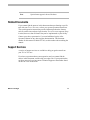
Before You Begin
The Operator's Manual explains the features, operation, and application of
the TOUCH TRACKER. It explains the tasks that can be performed when using
this product as part of your system.
In This Chapter
•
•
•
•
How to Use This Manual
Text Conventions
Related Documents
Support Services
How To Use This Manual
This manual is organized as follows:
•
Chapter 1: About Your New TOUCH TRACKER describes the TOUCH
TRACKER and its use. It also identifies buttons found on the keypad.
•
Chapter 2: Getting Started describes the fields on the TOUCH TRACKER
LCD. It also includes information about using the system lock, as well as
how to set and change the password.
•
Chapter 3: Everyday Tasks discusses how you use the TOUCH TRACKER
to control cameras. This chapter also includes setting up shots,
acknowledging alarms, and controlling auxiliaries, such as lights or
locks.
•
Chapter 4: Utilities and Advanced User Tasks describes system utilities
that can be run from the TOUCH TRACKER. These utilities include setting
the language, arming or disarming monitors, displaying the main menu
of the switching system, calibrating the Tracker Ball, and displaying the
firmware version.
•
Appendix A: Software License
Text Conventions
This book uses text in different ways to identify different kinds of
information.
italics
monospace
bold
vi
used for terms specific to TOUCH TRACKER and text
that requires emphasis
used for LCD messages and prompts, as well as items
that you select from the LCD menu
used for names of buttons on the keypad, for example,
Mon
vi
Operator's Manual
Note
Special notes appear in boxes like these.
Related Documents
If you cannot find the answers in this document about performing a specific
task with your TOUCH TRACKER, refer to your system operation instructions.
The system operation instructions provide information about the features,
such as satellite sites and user login, that the TOUCH TRACKER supports. Keep
in mind, however, that all features may not be implemented at your facility.
Contact your sales representative if you need additional copies of the
Operator's Manual or any other support documentation. The document
number for this manual is 8000-1657-02; use this number when ordering the
manual.
Support Services
A variety of support services are available to help you get the most from
your TOUCH TRACKER.
If you have a question about system operation, and you cannot find the
answer in this document, consult with your supervisor. If your question has
not been answered, you can contact Technical Support at the number found
on the rear cover of this book.
Before You Begin
vii
C H A P T E R
1
F
1
F
2
D ispla
U se
Site
Iris
Cl
PG ose
UP
y
ON
Aux
iliary
OFF
L
o
c
k
r
P
s
w
d
Se
Sho t
t
Call
ON
Prog
Mon
A rm
LC D
Cl ear
OF
F
Op
PG en
DN
Ru
n
Cle
ar
Ca libr
Ho
ld
Mon
Exit
CAM
B_P
Sa
lvo
ate
AS
Las
t
Nex
t
Ack
ENT
ER
About Your New TOUCH TRACKER
This chapter describes the features of the TOUCH TRACKER. It also identifies the
location of the buttons on the keypad, along with a brief description of their
functions.
In This Chapter
•
•
TOUCH TRACKER Features
TOUCH TRACKER Keypad Overview
TOUCH TRACKER Features
The TOUCH TRACKER is a video control station that functions the same as the Model
AD 2078 System Keyboard. It is compatible with all models of American Dynamics
switches. It allows you to operate cameras installed around your facility. You can
also control auxiliaries, such as lights and door locks, if your system is configured
with those features.
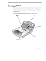
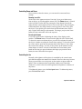
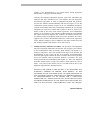
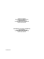
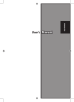
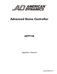
The following illustration identifies the features of the TOUCH TRACKER:
Zoom
LCD
F
1
F
2
Disp
lay
Use
r
ON
A ux
iliar
y
O FF
L
o
c
k
P
S
Sh et
s
w
d
ot
Site
Call
Iris
P ro
ON
Mon
g
PG
U
P
Ope
n
P
GD
A rm
LCD
Cle
ar
OF
F
Clo
se
Run
Hold
N
Cle
ar
Mon
Ex
it
Keypad
B_P
AS
Sa
lvo
CA
M
Cal
ibra
te
Las
t
Ne
xt
A
EN ck
TE
R
Focus
Tracker Ball
1-2
Operator's Manual
The Tracker Ball provides variable speed control of a camera's pan and tilt.
The zoom and focus buttons enable you to control a camera's zoom and focus.
The keypad enables you to call up video from individual cameras and control their
pre-programmed movement. It also provides for camera iris control, auxiliary
control, monitor selection, and the ability to clear alarms.
The LCD displays status information, the selected monitor and camera numbers, and
system lock status. It also displays system prompts and messages.
About Your New TOUCH TRACKER
1-3
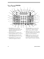
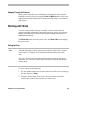
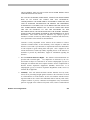
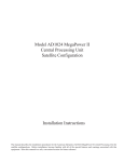
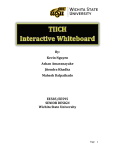
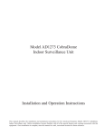
TOUCH TRACKER Overview
3
2
4
1
30
5
6
29
7
28
27
STS
MON
1024
CAM
8
L
9
26
Display
ON
1
Auxillary
25
2
ON
Mon Arm
3
OFF
User
24
Site
23
Iris
22
Close
PG UP
LCD
Clear
10
OFF
Set
Shot
Call
4
Prog
7
5
11
Callibrate
6
Run
12
Hold
8
B_PAS
9
Salvo
13
Open
PG DN
Clear
Mon
Exit
0
Last
Cam
Next
Ack
ENTER
14
21
20
19
1. Status field shows the status of the
connected switching system. Refer to the
appropriate operating instructions for
additional information.
2. Monitor field shows the number of the
monitor controlled by the TOUCH TRACKER.
3. Camera field shows the number of the
camera controlled by the TOUCH TRACKER.
4. Entry field shows the numbers being
entered on the keypad (see item 18).
1-4
18
17
16
15
5. Lock Status field shows the status of the
system lock. If “L” appears, the lock is
enabled; if blank, the lock is disabled.
6. Lock button toggles the state of the system
lock when used with the password. Refer to
Chapter 2 for specific instructions.
7. Pswd button sets or changes the system
lock password. There are two types of
passwords: Permanent and User Defined.
Refer to Chapter 2 for specific instructions.
Operator's Manual
8. LCD Clear button refreshes the LCD after
setting the password or performing
calibration. Compare to Clear (see 20).
9. Mon Arm On / Mon Arm Off buttons are
used to enable or disable system alarms
from appearing on monitors. Refer to the
appropriate operating instructions for
specific instructions. This feature is under
system lock protection.
10. Calibrate button is used to calibrate the
Tracker Ball and set the LCD language.
Refer to Chapter 4 for additional
instructions.
11. Run / Hold (↑
↑) buttons are used with
predefined monitor tours. Run starts a
monitor tour or universal (system) tour;
Hold halts the tour. These buttons also
operate during alarm tours. The Hold button
also serves as the Cursor Up function
during menu programming.
12. B-PAS button removes a selected camera's
input from a monitor tour. This button also
operates during alarm tours.
13. Salvo (↓
↓) displays a pre-defined group
(salvo) of camera inputs on a group of
contiguous monitors, beginning with the
currently selected monitor. Refer to the
appropriate operating instructions for
additional details. The Salvo button also
serves as the Cursor Down function
during menu programming.
14. Ack (Enter) button acknowledges system
alarms. The TOUCH TRACKER will beep until
the alarm is acknowledged. The Ack button
also serves as the Enter function during
menu programming.
About Your New TOUCH TRACKER
15. Next button displays the next camera's
input in a monitor tour that is currently on
hold. This button also operates during an
alarm tour.
16. Last (→
→) button displays the previous
camera's input in a monitor tour that is
currently on hold. This button also operates
during alarm tours. The Last button also
serves as the Cursor Right function during
menu programming.
17. Cam (←
←) button calls a specified camera's
input to the monitor that is currently
controlled by the TOUCH TRACKER. Refer to
Chapter 3 for specific instructions. The Cam
button also serves as the Cursor Left
function during menu programming.
18. Numeric Keypad is used to enter numbers
associated with Monitors, Cameras,
Passwords, and Users.
19. Mon (Exit) button calls a specified monitor
to be controlled by the TOUCH TRACKER.
Refer to Chapter 3 for specific instructions.
The Mon button also serves as the Exit
function during menu programming.
20. Clear button erases numbers entered on the
numeric keypad (see 18) before pressing an
action key, such as Cam, Mon, or Pswd.
Compare to LCD Clear (see 8).
21. Iris Open (PG-DN) button allows more
light into a camera controlled by the TOUCH
TRACKER. Refer to Chapter 3 for additional
details. The Iris Open button also serves as
the Page Down function during menu
programming.
1-5
22. Iris Close (PG-UP) button allows less
light into a camera controlled by the TOUCH
TRACKER. Refer to Chapter 3 for additional
details. The Iris Close button also serves as
the Page Up function during menu
programming.
23. Prog button is used to program monitor
tours and other system programming
features. Refer to the system operating
instructions for additional information. This
button is under system lock protection.
24. Site button controls satellite systems. Refer
to the system operating instructions for
additional information.
25. Shot Set / Shot Call buttons create and
display pre-defined scenes from a specified
camera. The Shot Set button creates the
pre-defined scenes and is under system lock
protection. The Shot Call button displays
the pre-defined scenes.
26. User button allows authorized users to log
on to the system. Refer to the system
operating instructions for additional details.
1-6
27. Display button is used to call up the main
menu of the attached switching system. It
also enables the use of the menu
programming buttons. This button is under
system lock protection.
28. Auxiliary On / Auxiliary Off buttons
activate and deactivate features such as
lights, locks, or alarms that can be
controlled by the TOUCH TRACKER. Refer to
Chapter 3 for additional information.
29. F2 button is a function key whose use is
determined by the system to which it is
connected. Refer to the system operating
instructions for additional information.
30. F1 button is a function key whose use is
determined by the system to which it is
connected. Refer to the system operating
instructions for additional information. The
F1 button also serves to set the baud rate
and display the firmware version of the
TOUCH TRACKER. For information about
setting the baud rate or displaying the
firmware version, refer to Chapter 4.
Operator's Manual
C H A P T E R
2
F
1
F
2
D ispla
U se
Site
Iris
Cl
PG ose
UP
y
ON
Aux
iliary
OFF
L
o
c
k
r
P
s
w
d
Se
Sho t
t
Call
ON
Prog
Mon
A rm
LC D
Cl ear
OF
F
Op
PG en
DN
Ru
n
Cle
ar
Ca libr
Ho
ld
Mon
Exit
CAM
B_P
Sa
lvo
ate
AS
Las
t
Nex
t
Ack
ENT
ER
Getting Started
This chapter provides an overview of the fields displayed on the LCD. It tells
you how to determine if the system lock is enabled, and it provides the
instructions for setting the system lock. It also explains how to set or change
the user defined password.
In This Chapter
•
•
•
LCD Display Overview
System Lock Feature
Working with Passwords
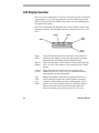
LCD Display Overview
The TOUCH TRACKER display is a 2 line by 16 character back lit LCD (liquid
crystal display). It serves the same purpose as the four LED displays on the
AD2078 system keyboard. In addition, it provides a field for identifying the
lock status of the system.
The LCD is divided into five functional areas: status, monitor, camera, entry
field, and lock status. The following illustration provides an overview of the
LCD.
Monitor
Camera
Entry
Field
Status
STS
MON
CAM
003
0005
1024
L
Lock
Status
Status
(STS)
Monitor
(MON)
Camera
(CAM)
Entry
Field
Lock
Status
2-2
3-digit field that provides the current status of the connected
switching system. Refer to your switching system's operating
instructions for information about the displayed status.
3-digit field that shows which monitor is being controlled by the
TOUCH TRACKER. This monitor is also referred to as the “called”
monitor.
4-digit field that shows which camera is currently being
controlled by the TOUCH TRACKER. The information from the
camera appears on the called monitor.
Displays the numbers entered by an operator from the TOUCH
TRACKER numeric keypad. This field is limited to four digits.
1-character field that shows the state of the System Lock. “L”
appears if the lock is enabled. If the lock is disabled, nothing
appears in the field. The System Lock function limits the
activities available to the operator of the TOUCH TRACKER.
Operator's Manual
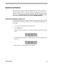
System Lock Feature
The system lock feature prevents unauthorized use of the TOUCH TRACKER
advanced features. When “L” appears in the lower right corner of the LCD,
operators cannot access certain system features. The features that cannot be
accessed are: Shot Set, Mon Arm On, Mon Arm Off, Prog, Display, and the
dual function menu programming keys, such as PG DN and Enter.
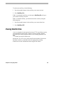
Enabling and Disabling the System Lock
The system lock feature is enabled or disabled by entering the password. For
more information about the password, refer to "Working with Passwords" in
this chapter.
1. Use the numeric keypad to type the password.
2. Press Lock button.
If the lock has been enabled, “L” appears in the lower right corner of the
LCD.
STS
MON
CAM
003
0005
1024
L
If the lock has been disabled, nothing appears in the lower right corner of
the LCD.
STS
MON
003
CAM
0005
1024
3. Repeat steps 1 and 2 to toggle the system lock.
Getting Started
2-3
Working with Passwords
Passwords allow you to limit access to advanced features of the TOUCH
TRACKER, such as arming or disarming monitors and the dual function menu
programming keys (such as, PG DN, PG UP). Passwords can be 1 to 4 digits
in length. There are two types of passwords available on the system:
permanent and user defined.
The permanent password is set at the factory and cannot be changed or
removed. Its value is 1963.
The user defined password is set using Pswd button. It also provides access
to the advanced features of the TOUCH TRACKER. You can change or disable
this password using the set password feature.
Note
Anyone who knows the permanent password will be able to gain access to
the advanced features of the TOUCH TRACKER. The permanent password
can override a system lock that has been set using the user defined
password. Be aware of this capability before passing out the permanent
password to multiple users.
Setting or Changing a Password
The following instructions imply that the permanent password can be
changed by using these steps. The permanent password cannot be changed or
removed.
When setting a user defined password for the first time, you must first enter
the permanent password.
2-4
Operator's Manual
To set or change a password, do the following:
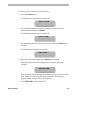
1. Press the Pswd button.
The following message appears on the LCD:
Enter Old PSWD
2. Use the number buttons to enter the permanent or the current user
defined password, then press Pswd.
The following message appears on the LCD:
Enter New PSWD
3. Use the number buttons to enter the new password. Press Pswd when
finished.
The following message appears on LCD:
ReEnter PSWD
4. Enter the new password again. Press Pswd when finished.
If the password successfully changed, you will see the following
message:
Successful PSWD
If the password was not changed successfully, the TOUCH TRACKER will
beep, and the LCD refreshes and displays the status fields. If this
happens, return to step 1 and repeat the process.
5. Press LCD Clear to refresh the LCD.
Getting Started
2-5
C H A P T E R
3
F
1
F
2
D ispla
U se
Site
Iris
Cl
PG ose
UP
y
ON
Aux
iliary
OFF
L
o
c
k
r
P
s
w
d
Se
Sho t
t
Call
ON
Prog
Mon
A rm
LC D
Cl ear
OF
F
Op
PG en
DN
Ru
n
Cle
ar
Ca libr
Ho
ld
Mon
Exit
CAM
B_P
Sa
lvo
ate
AS
Las
t
Nex
t
Ack
ENT
ER
Everyday Tasks
This chapter describes everyday tasks that all users can perform on the
TOUCH TRACKER. It also explains how to zoom, focus and operate the iris of a
camera with the TOUCH TRACKER. In addition, it explains procedures for
acknowledging alarms and controlling auxiliaries, such as lights or door
locks.
In This Chapter
•
•
•
•
•
•
•
•
Selecting Monitors
Controlling Cameras
Working with Shots
Running Monitor Tours
Acknowledging Alarms
Auxiliary Control
Viewing Satellite Sites
Setting Up Users
Selecting Monitors
Monitors display the video from the cameras installed around your facility.
Each monitor has an identification number associated with it. To select a
monitor, use the number buttons to enter the monitor number, and then press
Mon. Once a monitor has been called by the TOUCH TRACKER, you will see
its identification number in the MON field of the LCD. This monitor is
referred to as the called monitor.
The number of monitors available to display video input is determined by
your system configuration. Refer to the appropriate operating instructions to
determine the number of supported monitors.
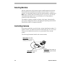
Controlling Cameras
Each camera installed at your facility has a unique identification number. To
control a camera, you must first select the camera with your TOUCH TRACKER.
Then you can control the zoom, focus, iris, pan and tilt of the selected
camera.
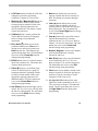
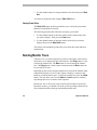
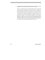
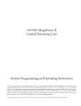
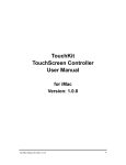
The following illustration identifies the camera controls:
Zoom button: Press away
from you to zoom in; press
towards you to zoom out.
F
1
F
2
Disp
lay
User
O
A uxi N
li ary
O FF
oL
c
k
P
Set
Site
Iris
C
P Glose
UP
ws
d
Shot
Call
ON
M on
P rog
Ar m
LCD
C lear
OFF
O
P Gpen
DN
Run
Clear
C ali
Hold
M
Ex iton
CA
M
bra
te
B_
PAS
Sal
vo
La st
Ne
xt
Ack
ENTE
R
Tracker Ball: Controls the
camera's pan and tilt.
3-2
Focus button: Press away from
you to focus near; press towards
you to focus far.
Operator's Manual
The number of cameras that can be controlled by the TOUCH TRACKER
depends upon the system configuration. Refer to the system operating
instructions for additional information about the number of cameras your
system can support.
Selecting a Camera
Each camera has a unique number associated with it. To select a camera, use
the number buttons to enter the camera number, then press Cam. The video
from the camera appears on the called monitor, and the camera number
appears in the bottom left corner of the monitor. Once a camera has been
called by the TOUCH TRACKER, you will also see its number displayed in the
CAM field of the LCD.
Controlling a Camera's Pan and Tilt
Once you have selected a camera, you can manually control the movement of
that camera. Pan is the side-to-side movement of the camera; tilt is the up
and down movement of the camera.
The Tracker Ball controls the panning and tilting of cameras connected to
the system. When the Tracker Ball moves to the right, the camera pans to the
right; when the Tracker Ball moves to the left, the camera pans to the left. By
moving the Tracker Ball up or down, the camera will tilt to the appropriate
angle.
For cameras that support the variable speed features of the TOUCH TRACKER,
how fast or slowly the camera moves is proportional to how far you move the
Tracker Ball from its center position. If you move the Tracker Ball slightly to
the right, the camera will pan slowly to the right. As you move the Tracker
Ball farther to the right, the camera's panning speed will increase until it
reaches its maximum speed. The camera continues to move until the Tracker
Ball is in the center position.
You can simultaneously pan and tilt the camera for diagonal movement. For
example, move the Tracker Ball diagonally up and to the right; this moves
the camera up and to the right.
Chapter 3: Everyday Tasks
3-3
Controlling Zoom and Focus
Once you have selected a camera, you can control its zoom and focus
settings.
Zooming In and Out
Zoom refers to the apparent action of “moving” closer to or farther away
from an object, as seen through the camera lens. The Zoom button is located
to the left of the Tracker Ball. By pressing the Zoom button forward, the
image from the camera appears to move closer to the object. By pressing the
Zoom button back, the image from the camera appears to move away from
the object. If you quickly press and release the Zoom button, there will be
only a slight visible change on the monitor. The longer you press the Zoom
button, the more noticeable will be the response.
Focusing the Camera
Focus refers to the action of adjusting the clarity of the display on the
monitor. The Focus button is located on the right side of the Tracker Ball.
To focus the camera on a distant object, press the Focus button forward (if
the object is farther away than the current focus setting). To focus the camera
on a nearer object, press the Focus button back (if the object is closer than
the current focus setting). You will see the picture on the monitor become
either sharper or fuzzier. Like the Zoom button, the Focus button reacts
based on how long you press the button; the longer you press the Focus
button, the more noticeable the response.
Controlling the Iris
Normally, the brightness of the picture is controlled by the camera's auto
gain function and the auto/manual iris function. However, there may be times
when you would like to see the picture on the monitor to appear darker or
lighter. There are buttons on the keypad that enable you to control the
camera's iris, which is the device that regulates the brightness or darkness of
the picture.
To brighten the picture, press the Iris Open button. To darken the picture,
press the Iris Close button.
3-4
Operator's Manual
Stepping Through the Cameras
Some systems may allow you to manually step through all of the cameras
installed at your facility by pressing the Last and Next buttons. Refer to the
appropriate operating instructions to determine if this feature is available on
your system.
Working with Shots
A shot is a memorized location or scene that a camera with motorized
pan/tilt can display on demand. Depending upon your system, you can have
multiple pre-defined shots. Refer to the system operating instructions for
additional information.
The Shot Set button saves the preset scene; the Shot Call button displays
the preset scene.
Setting Up Shots
Note
The Shot Set button is under system lock protection. Refer to the “System
Lock Feature” in Chapter 2 for information about disabling the system
lock.
You can overwrite an existing shot without warning using the following
procedure. Use caution to ensure that you do not overwrite a shot that you
want to keep.
To set up a shot, do the following:
1. Use the number buttons to select the camera for which you are setting up
the shot, then press Cam.
2. Using the Tracker Ball, Zoom, Focus, and Iris controls, adjust the
camera until you have the scene that you want to save.
Chapter 3: Everyday Tasks
3-5
3. Use the number buttons to assign a number to this shot, then press Shot
Set.
You can now display this shot using the Shot Call button.
Viewing Preset Shots
The Shot Call button on the keypad allows you to call up the preset shots
that have been defined for cameras.
The following procedure describes how to display a preset shot.
1. Use the number buttons to enter the number of the camera whose shot
you want to display. Then press the Cam button.
2. Use the number buttons to enter the number of the shot you want to
display, then press the Shot Call button.
The camera will immediately point to the preset shot, then zoom and focus
automatically.
Running Monitor Tours
A monitor tour is a selected sequence of camera video inputs, with selected
dwell times, to be displayed on the called monitor. The Prog button is used
to define the monitor tour. The Run button is used to initiate the monitor
tour. The Prog button is under system lock protection; the Run button can
be accessed by all users.
Depending on the system setup and monitor tour selected, the monitor either
continuously displays a series of video inputs or displays a sequence and
holds on a selected camera input. To pause the monitor tour, press the Hold
button. This will allow you to use the Next and Last buttons to manually
step through the series of cameras in the sequence.
Because the TOUCH TRACKER works with all current models of American
Dynamics switches, you should refer to the system operating instructions for
more information about setting up and running monitor tours.
3-6
Operator's Manual
Bypassing Camera Input
If you want skip a specified camera's input from a monitor tour, use the
B-PAS button when the monitor tour is in a Hold pattern. Refer to the
appropriate operating instructions for additional information.
Universal (System) Tours
Another type of tour that your system may support is the Universal Tour. A
universal tour is a programmed sequence of cameras with assigned dwell
times, presets, auxiliaries, and connect next designations. This is also known
as the System Tour. For more information about the universal tour, refer to
the appropriate operating instructions.
To run a universal tour, do the following:
1. Use the number buttons to enter the tour number, then press Run.
2. Press Ack.
Once the universal tour is running, the Next, Last, Hold, and B-PAS
buttons operate in the same manner as with the monitor tour.
Running Salvos
A salvo displays a pre-defined group (salvo) of camera inputs to a group of
contiguous monitors, beginning with the presently controlled monitor. The
Salvo button is used to initiate the display of the cameras input. Because the
TOUCH TRACKER works with all current models of American Dynamics
switches, you should refer to the system operating instructions for more
information about setting up and running salvos.
Acknowledging Alarms
Your system can be configured to handle multiple alarms. Each alarm can be
configured to automatically call up video and initiate an auxiliary, such as an
audible alarm. In addition, whenever an alarm is triggered, the TOUCH
Chapter 3: Everyday Tasks
3-7
TRACKER beeps, signaling an active alarm. The TOUCH TRACKER beeps
intermittently until the alarm is cleared.
To acknowledge an active alarm, press the Ack button. Continue to press the
Ack button until all active alarms have been cleared. Once all active alarms
have been acknowledged, the TOUCH TRACKER will stop beeping.
Refer to the appropriate operating instructions to determine the number of
alarms your system can handle, as well as to determine how many alarms can
be active at one time.
If a monitor is armed for alarm display, the Run, Hold, B-PAS, Next, and
Last buttons are used to control the alarm sequence. Press Run to start the
Alarm Tour of the inputs in an abnormal state. Press Hold to pause the
Alarm Tour. Press Next to step forwards through an Alarm Tour that is on
hold; press Last to step backwards through an Alarm Tour that is on hold.
Press B-PAS to remove a camera from the active Alarm Tour.
For additional information about Alarm Tours, refer to the appropriate
operating instructions.
Auxiliary Control
An auxiliary is a device, such as a light, audible alarm, or door lock, that can
be controlled using the TOUCH TRACKER. Auxiliaries can also be initiated
automatically in response to an alarm when they have been configured to do
so. The Auxiliary On and Auxiliary Off buttons are used to control the
operation of both momentary and latched auxiliaries.
A momentary auxiliary remains active as long as its control button is
pressed. An example of a momentary auxiliary is a door that remains
unlocked as long as the Auxiliary On button is pressed. When the button is
released, the door returns to its locked state.
A latched auxiliary remains active until it is deactivated using the
appropriate off switch. An example of latched auxiliary is a light. When the
Auxiliary On button is pressed, the light is turned on. When the Auxiliary
Off button is pressed, the light is turned off.
3-8
Operator's Manual
To activate an auxiliary, do the following:
1. Press the number buttons for the auxiliary you want to activate.
2. Press Auxiliary On.
If this is a momentary auxiliary, you must press Auxiliary On as long as
you want the auxiliary activated.
If this is a latched auxiliary, you must deactivate the auxiliary using the
following steps:
1. Press the number buttons for the auxiliary you want to deactivate.
2. Press Auxiliary Off.
Viewing Satellite Sites
A site is a complete closed caption television (CCTV) surveillance system,
providing both local and remote control of resources within a satellite
network. If your facility supports satellite site switching capabilities, the
Site button accesses the satellite sites.
Because the TOUCH TRACKER works with all current models of American
Dynamics switches, you should refer to the appropriate operating
instructions for more information about using the Site feature.
Chapter 3: Everyday Tasks
3-9
Setting Up Users
Users are people authorized to operate the TOUCH TRACKER. Users can be
classified by their levels of privilege on the system. Some users may have
access to only the basic system functions, such as selecting cameras and
monitors. Other users may have access to the more advanced features of the
system, such as arming and disarming monitors. Once users have been set
up, the User button allows authorized personnel to log in to the system.
Because the TOUCH TRACKER works with all current models of American
Dynamics switches, you should refer to the appropriate operating
instructions for more information about setting up users.
3-10
Operator's Manual
C H A P T E R
4
F
1
F
2
D ispla
U se
Site
Iris
Cl
PG ose
UP
y
ON
Aux
iliary
OFF
L
o
c
k
r
P
s
w
d
Se
Sho t
t
Call
ON
Prog
Mon
A rm
LC D
Cl ear
OF
F
Op
PG en
DN
Ru
n
Cle
ar
Ca libr
Ho
ld
Mon
Exit
CAM
B_P
Sa
lvo
ate
AS
Las
t
Nex
t
Ack
ENT
ER
Utilities and Advanced User Tasks
This chapter describes tasks that should only be performed by advanced
users of the TOUCH TRACKER. These tasks include setting the language,
arming and disarming monitors, displaying the main menu of the switching
system, calibrating the TOUCH TRACKER, and displaying the firmware version.
Many of these tasks are under system lock protection.
In This Chapter
•
•
•
•
•
•
•
Selecting the Language
Arming / Disarming Monitors
Displaying the Switching System Main Menu
Calibrating the Tracker Ball
Displaying the Tracker Ball Calibration Values
Displaying the Firmware Version
Setting the Baud Rate
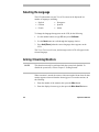
Selecting the Language
The LCD information on your TOUCH TRACKER can be displayed in a
number of languages, including:
•
•
•
English
German
French
•
•
•
Portuguese
Spanish
Italian
To change the language that appears on the LCD, do the following:
1. Use the number buttons to type 35, then press Calibrate.
2. Use the Next button to scroll through the language choices.
3. Press Ack (Enter) when the correct language choice appears on the
LCD.
The TOUCH TRACKER will reset, and messages on the LCD will appear in the
selected language.
Arming / Disarming Monitors
NOTE
This function can only be performed with the system lock disabled. To
disable the system lock, refer to Chapter 2 “Getting Started.”
When a monitor is armed, the camera video associated with an alarm for that
monitor appears when an alarm has been triggered. To arm the monitor, do
the following:
1. Enter the number of the monitor, then press the Mon button.
2. Enter the display/clearance type, then press the Mon Arm On button.
4-2
Operator's Manual
When a monitor is disarmed, the camera video from alarms is not displayed
when an alarm has been triggered. To disarm the monitor, do the following:
1. Enter the number of the monitor, then press the Mon button.
2. Enter the display/clearance type, then press the Mon Arm Off button.
For specific information about arming and disarming monitors, refer to the
appropriate operating instructions for your system.
Once a monitor is armed for alarm display, the Run, Hold, B-PAS, Next,
and Last buttons are used to control the Alarm Tour. Press Run to start the
Alarm Tour of the inputs in an abnormal state. Press Hold to pause the
Alarm Tour. Press Next to step forwards through an Alarm Tour that is on
hold; press Last to step backwards through an Alarm Tour that is on hold.
Press B-PAS to remove a camera from the active Alarm Tour.
For additional information about Alarm Tours, refer to the appropriate
operating instructions.
Displaying the Switching System Main Menu
NOTE
This function can only be performed with the system lock disabled. To
disable the system lock, refer to Chapter 2 “Getting Started.”
The Display button allows you to view the main menu of the attached
switching system. When the main menu for the switching system has been
displayed, the functions associated with the dual function buttons are
enabled. These functions are: PG DN, PG UP, Exit, Enter, Cursor Left (←),
Cursor Right (→), Cursor Up (↑), and Cursor Down (↓).
For information about the what tasks you can do from the main menu, refer
to the appropriate system's operating instructions. When you complete using
the main menu, press Display. The dual function buttons will return to their
normal operation.
Chapter 4: Utilities and Advanced User Tasks
4-3
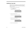
Calibrating the Tracker Ball
Calibration “tunes” the Tracker Ball sensors for maximum range of motion
and balance. This function is performed at the factory prior to shipping.
However, if you need to calibrate the Tracker Ball, the following procedure
describes how to do this.
To calibrate the Tracker Ball, do the following:
1. Press the Calibrate button.
The following message appears on the display:
Push Tracker Ball Left
2. Push the Tracker Ball to the left.
The following message appears on the display:
Push Tracker Ball Right
3. Push the Tracker Ball to the right.
The following message appears on the display.
Push Tracker Ball Down
4. Push the Tracker Ball towards you.
4-4
Operator's Manual
The following message appears on the display:
Push Tracker Ball Up
5. Push the Tracker Ball away from you.
The following message appears on the display:
Release Tracker Ball
6. Release the Tracker Ball.
Tracker Ball calibration is complete.
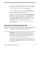
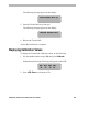
Displaying Calibration Values
To display the Tracker Ball calibration values, do the following:
1. Use the number buttons to type 34, then press Calibrate.
Information similar to the following will appear on the LCD:
LD2 R00 UD6 D9D
10 10 10 10
2. Press LCD Clear to refresh the LCD.
Chapter 4: Utilities and Advanced User Tasks
4-5
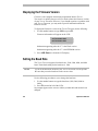
Displaying the Firmware Version
Firmware is the computer instructions programmed into the TOUCH
TRACKER. It is unlikely that you will ever need to know the firmware version
of your TOUCH TRACKER. However, if you should experience a problem with
your TOUCH TRACKER, you may need to provide information about the
firmware version.
To display the firmware version of the TOUCH TRACKER, do the following:
1. Use the number buttons to type 100; then press F1.
Firmware information will appear on the LCD.
F 0701-2940-0100
E 0701-2941-0100
Information appearing after the “F” is the Flash version.
Information appearing after the “E” is the EEPROM version.
2. Press LCD Clear to refresh the LCD display.
Setting the Baud Rate
The TOUCH TRACKER supports four baud rates: 1200, 2400, 4800, and 9600
baud. The default setting for the baud rate is 1200.
NOTE
If you set the baud rate incorrectly, the TOUCH TRACKER will not operate.
Be sure that you set the baud rate to the correct value.
Use the following procedure to set or change the baud rate.
1. Use the number buttons to type the baud rate (1200, 2400, 4800 or
9600).
2. Press F1 (located to left of the LCD).
No prompts appear on the screen to inform you that the baud rate has been
changed.
4-6
Operator's Manual
A P P E N D I X
A
F
1
F
2
D ispla
U se
Site
Iris
Cl
PG ose
UP
y
ON
Aux
iliary
OFF
L
o
c
k
r
P
s
w
d
Se
Sho t
t
Call
ON
Prog
Mon
A rm
LC D
Cl ear
OF
F
Op
PG en
DN
Ru
n
Cle
ar
Ca libr
Ho
ld
Mon
Exit
CAM
B_P
Sa
lvo
ate
AS
Las
t
Nex
t
Ack
ENT
ER
Software License Agreement
By using the TOUCH TRACKER software, you accept the terms and conditions
of this license agreement. Read this license agreement carefully.
Software License Agreement
A-1
SOFTWARE LICENSE AGREEMENT
A-2
1.
General. Software is being licensed to the Customer pursuant to the following
terms and conditions, which supplement any purchase or lease agreement (the
"Equipment Agreement") between Customer and Sensormatic Electronics
Corporation ("SEC"). By accepting receipt of, or by using, such Software, the
Customer agrees to be bound by the terms of this Software License Agreement
(the "License Agreement"). The term “Software” means all computer programs,
instructions, data and databases, in any form or on any media, supplied by SEC
(or its suppliers) to Customer and all current and future versions, revisions,
updates, upgrades and new releases thereof. Except as otherwise provided in this
License Agreement, the terms and conditions of the Equipment Agreement apply
to the Software, the related technical and user manuals ("Documentation") and
the license provided herein.
2.
License. SEC licenses the Software and the Documentation to Customer, for the
license fee(s) set forth (or included in the product prices set forth) in the
Equipment Agreement and subject to the terms and conditions of this License
Agreement. The license is non-exclusive and is limited by the terms of this
License Agreement. Customer may not transfer the license except to a party to
whom the equipment is transferred and then only with the written consent of
SEC. The Software and Documentation are being licensed and not sold or leased
to Customer. SEC or its suppliers who have authorized SEC to sublicense
certain of the Software and Documentation retain ownership of the Software and
Documentation. The Software is being licensed for use only on (i) a single
computer (A) owned or leased by Customer and identified in the Equipment
Agreement or (B) otherwise identified in the Documentation as compatible with
the Software, or (ii) a back-up machine if and so long as such computer becomes
temporarily inoperable.
3.
Term. The term of the license is perpetual, except that it will terminate
automatically if Customer sells or otherwise disposes of the Software or its
related equipment or Customer breaches any provision of this License
Agreement or the Equipment Agreement. If the license terminates, SEC will
have the right to take possession of all copies of the Software and
Documentation in the possession of Customer or to require Customer to destroy
all such copies and certify such destruction in writing to SEC.
Operator's Manual
4.
Ownership. Customer agrees and acknowledges that (i) SEC (or its suppliers) is
the sole owner of the Software and Documentation (including all copies thereof,
in whatever form or media, delivered to or made by Customer) and all patent,
copyright and other intellectual property rights with respect thereto and (ii) the
Software and Documentation constitute valuable trade secrets, confidential
information and proprietary properties of SEC and its suppliers. Accordingly,
Customer agrees that it will have no rights in the Software or Documentation
other than those granted under this License Agreement and agrees to abide by the
restrictions on its use of the Software and Documentation set forth in Section 5
of this License Agreement.
5. Use and Copies. Customer may use the Software and Documentation only in
conjunction with the other equipment identified in the Equipment Agreement, as
part of the access control, closed circuit television or other security system being
acquired from SEC and for Customer's internal business purposes. SEC will
furnish the Software to Customer solely in object code form.
Customer may make up to 2 copies of the Software solely for back-up and
archival purposes. Customer will not remove or modify the copyright and other
proprietary notices and legends of SEC and its suppliers contained in the
Software and Documentation and will reproduce all such notices and legends on
all copies of the Software made by Customer. Customer may not make copies of
the Documentation, but may obtain additional copies of the Documentation from
SEC at its established rates. Except as permitted above, copying of the Software
and Documentation is forbidden.
Customer will not sell, assign, sublicense or transfer this license or sell or
otherwise transfer the Software or Documentation (or any portion thereof) to
others. Customer will maintain the Software and Documentation in confidence
and not disclose any data or other information contained in the Software or
Documentation to any party, except for Customer's employees and agents who
require access to the Software for the purposes of Customer's internal business
and who use it in accordance with the terms of this License Agreement.
Customer will not use the Software for the provision of time-sharing services to
others. Customer will not modify the Software or decompile, disassemble or
otherwise reverse engineer the Software and will not have the right to create
derivative works of the Software, including, without limitation, translated or
localized versions of the Software. Customer will not export or re-export the
Software License Agreement
A-3
Software or the Documentation or any portion thereof without appropriate
United States or foreign governmental licenses.
Customer will implement appropriate measures, such as the requirement that
employees and others permitted access to the Software enter into appropriate
non-disclosure agreements, to satisfy its obligations hereunder and, generally,
will treat the Software and Documentation with the same degree of care and
confidentiality which Customer provides for its own confidential information.
Customer acknowledges that it may be held legally responsible for any copyright
infringement or trade secret violation that is caused, in whole or in part, by its
failure to abide by the terms of this License Agreement. Since unauthorized
transfer, use or disclosure of the Software and Documentation would diminish
their value to SEC and its suppliers, who would have no adequate remedy at law
if Customer breaches its obligations under this License Agreement, SEC and its
suppliers (who are direct and intended beneficiaries of this License Agreement)
will be entitled to injunctive relief, in addition to such other remedies and relief
that would be available to them in the event of such a breach.
6.
Limited Warranty; Limitation of Liability. The provisions of the Equipment
Agreement respecting maintenance and warranty will not apply to the Software
or the Documentation, unless specifically stated otherwise and agreed to in
writing by both parties. SEC's sole warranties with respect to the Software and
Documentation are that (i) SEC has title to the Software and Documentation
and/or the right to grant Customer the license set forth in this License Agreement
and (ii) the magnetic media on which the Software is recorded is free from
defects in materials and workmanship under normal use. SEC's sole obligation
under this warranty will be to replace any defective media returned to it free of
charge. The period of this warranty will be 12 months from the date of the
Equipment Agreement (the “Warranty Period”).
EXCEPT AS SET FORTH IN THIS SECTION 6, SEC DISCLAIMS ANY
WARRANTY, EXPRESS OR IMPLIED, WITH RESPECT TO THE
SOFTWARE OR THE DOCUMENTATION OR THEIR OPERATION OR
USE, INCLUDING, WITHOUT LIMITATION, ANY IMPLIED WARRANTY
OF MERCHANTABILITY OR OF FITNESS FOR A PARTICULAR
PURPOSE OR USE. SOME STATES DO NOT ALLOW THE EXCLUSION
OF IMPLIED WARRANTIES, SO THE ABOVE EXCLUSION DOES NOT
APPLY IN SUCH STATES. THIS WARRANTY GIVES YOU SPECIFIC
A-4
Operator's Manual
LEGAL RIGHTS, AND YOU MAY ALSO HAVE OTHER RIGHTS THAT
VARY FROM STATE TO STATE.
SEC AND ITS SUPPLIERS, EMPLOYEES, AGENTS AND FRANCHISEES
WILL IN NO EVENT BE LIABLE FOR ANY INCIDENTAL,
CONSEQUENTIAL OR OTHER DIRECT OR INDIRECT DAMAGES (FOR
LOSS OF BUSINESS INFORMATION OR PROFITS OR OTHERWISE)
SUFFERED BY CUSTOMER, ANY OF ITS EMPLOYEES OR AGENTS OR
ANY OTHER PERSON ARISING OUT OF OR IN CONNECTION WITH
THE USE OR INABILITY TO USE THE SOFTWARE OR THE
DOCUMENTATION, OR THE MAINTENANCE OR SUPPORT THEREOF,
EVEN IF THEY HAVE BEEN ADVISED OF THE POSSIBILITY OF SUCH
DAMAGES. SEC neither assumes nor authorizes any employee, agent or
franchisee to assume for SEC any other liability in connection with the license,
use or performance of the Software or Documentation.
Customer is solely responsible for the selection of the Software to achieve
Customer’s intended results, for the conformity of the computer on which the
Software is run to SEC’s specifications or requirements and for the maintenance
of such computer in good working order and repair. SEC’s suppliers do not
warrant the Software, assume any liability regarding the use of the Software or
undertake to provide any maintenance, support or information regarding the
Software.
7.
U.S. Government Restricted Rights. The Software and Documentation are
provided with restricted rights. Use, duplication or disclosure by the U.S.
Government is subject to restrictions as set forth in subparagraphs (c)(1)(ii) of
the Rights in Technical Data and Computer Software Clause of Department of
Defense Federal Acquisition Supplement (DFARS) 252.227-7013 or in
subparagraph (g)(3)(i) of Federal Acquisition Regulations (FAR) 52.227-14,
Alternate III, as applicable.
8.
Indemnity. SEC will defend and hold Customer harmless from any claim,
action, suit or proceeding brought against Customer to the extent that it is based
on a claim that the use of the Software, as such, in accordance with this License
Agreement and not as a result of the combination thereof with any other article,
computer software or process, constitutes an infringement of any United States
patent or copyright or the violation of any trade secret, if SEC is notified thereof
Software License Agreement
A-5
promptly after its commencement and is given control of the defense thereof and
any negotiations for its settlement and full cooperation by Customer.
SEC will pay all damages and costs awarded against Customer in connection
with any such claim, except that SEC will not be liable for any amounts paid
under any compromise or settlement made without its consent. If the Software is
either claimed or held to infringe or violate any patent or copyright, SEC may, at
its sole option and expense, and Customer will permit SEC to, procure for
Customer the right to continue using the Software or modify it so that it becomes
non-infringing or replace it with a non-infringing counterpart. If neither of such
alternatives is available on terms which are reasonable in SEC's judgment,
Customer will return all copies of the Software and Documentation in the
possession of Customer to SEC, at SEC's request, and SEC will refund a
reasonable portion of the license fees paid by Customer to SEC. This Section 8
sets forth SEC's entire liability regarding infringement and the like.
A-6
Operator's Manual
F
1
F
2
D ispla
U se
Site
Iris
Cl
PG ose
UP
y
ON
Aux
iliary
OFF
L
o
c
k
r
P
s
w
d
Se
Sho t
t
Call
ON
Prog
Mon
A rm
LC D
Cl ear
OF
F
Op
PG en
DN
Ru
n
Cle
ar
Ca libr
Ho
ld
Mon
Exit
CAM
B_P
Sa
lvo
ate
AS
Las
t
Nex
t
Ack
ENT
ER
Glossary
alarm
The system's response when a camera input changes from its normal state to
its abnormal state (if the system has been configured to respond to such a
condition). When an alarm is triggered, the TOUCH TRACKER beeps until you
acknowledge the alarm via the Ack button.
automatic system function
A system operation that, once you program it, can be initiated automatically
via the TOUCH TRACKER. Shots, monitor tours, and alarms are examples of
automatic system functions
auxiliary
Devices such as lights, audible alarms, door locks, that can be controlled via
the TOUCH TRACKER. Auxiliaries can also be initiated automatically in
response to an alarm when they have been configured to do so. See also
latched auxiliary and momentary auxiliary.
calibrate
To check or adjust the graduations of the Tracker Ball. Do this if the Tracker
Ball is not responding as expected when you move it.
Called Monitor
The monitor that displays the video that is being controlled by the TOUCH
TRACKER.
camera command
A directive issued to the camera via the TOUCH TRACKER—a pan, tilt, zoom,
focus, or iris command.
camera control mode
The condition of the TOUCH TRACKER when an operator is manually selecting
or controlling cameras, selecting a monitor, displaying shots, and running a
monitor tour.
dwell time
The amount of time that an event within the monitor tour will remain on the
monitor before it is replaced by another event.
fixed shot
The view of whatever a camera happens to be “looking at” when it is called
up on the monitor.
focus
The process of adjusting the clarity of a scene or an object, as seen through a
camera
input
A device such as a smoke detector or twilight sensor that, when configured
to do so, can trigger an alarm when it undergoes a change in state.
iris
The camera component that determines how much light enters the camera.
By adjusting the iris, you can adjust the brightness and darkness of the video
on the monitor.
G-2
Operator's Manual
keypad
The portion of the TOUCH TRACKER containing the buttons that enable
you to call up an individual camera, control a camera's iris, display shots, run
Monitor Tours, and arm or disarm monitors.
LCD
Liquid Crystal Display. The portion of the TOUCH TRACKER that enables
you to view which the status of the connected switch, the monitor and
camera currently being controlled, the numbers entered from the keypad, and
the state of the system lock feature. In addition, the LCD displays system
prompts when setting the password or when calibrating the Tracker Ball.
latched auxiliary
An auxiliary that remains active until it is deactivated using the appropriate
off switch. An example of latched auxiliary is a light. When the Auxiliary
On button is pressed, the light is turned on. When the Auxiliary Off button
is pressed, the light is turned off. See also auxiliary and momentary
auxiliary.
momentary auxiliary
An auxiliary that is active as long as its control button is pressed. An
example of a momentary auxiliary is a door that remains unlocked as long as
the Auxiliary On button is pressed. When the button is released, the door
returns to its locked state. See also auxiliary and latched auxiliary.
monitor
The screen where camera video is displayed.
monitor tour
A collection of video inputs with specified dwell times that are displayed one
after the other on the called monitor. It provides a broad surveillance of a
facility.
pan
Side to side camera movement.
Glossary
G-3
permanent password
The password that is preset at the factory. It is used to enable or disable the
system lock. This password cannot be changed or removed from the TOUCH
TRACKER by using the Pswd button. The permanent password can be used
to override the user defined password. See also system lock and user defined
password.
programmable camera
A camera that can be programmed to perform automatic functions.
salvo
A group of pre-defined camera inputs displayed on a group of contiguous
monitors, beginning with the currently controlled monitor.
shot
A preset view from a camera that can be automatically and instantaneously
displayed on a monitor, regardless of where that camera is currently pointing.
system lock
A feature of the TOUCH TRACKER that prevents unauthorized use of certain
functions of the system. When the system lock is enabled, “L” appears in the
lower right corner of the LCD. The system lock is enabled or disabled by
using the permanent or user defined password. See also permanent password
and user defined password.
tilt
Up and down camera movement.
toggle
To alternate the current state of the system lock feature.
TOUCH TRACKER
The video control station that provides you with easy access to various video
control features. It is functionally equivalent to the AD2078 system
keyboard.
G-4
Operator's Manual
Tracker Ball
The portion of the TOUCH TRACKER that enables you to pan and tilt the
camera and scroll through the selections on the menu.
universal (system) tour
A programmed sequence of cameras with assigned dwell times, presets,
auxiliaries, and connect next designations.
user defined password
The password that is set or changed using the Pswd button on the TOUCH
TRACKER. It is used to enable or disable the system lock. The user defined
password can be used to override the permanent password. See also
permanent password and system lock.
utility
A menu selection that either assists you in self-help system diagnostics, or
provides you with a convenience feature for system operation. The utilities
are accessed via special keystrokes.
zoom
The apparent action of “moving” closer to or away from an object, as seen
through the camera lens.
Glossary
G-5
F
1
F
2
D ispla
U se
Site
Iris
Cl
PG ose
UP
y
ON
Aux
iliary
OFF
L
o
c
k
r
P
s
w
d
Se
Sho t
t
Call
ON
Prog
Mon
A rm
LC D
Cl ear
OF
F
Op
PG en
DN
Ru
n
Cle
ar
Ca libr
Ho
ld
Mon
Exit
CAM
B_P
Sa
lvo
ate
AS
Las
t
Nex
t
Ack
ENT
ER
Index
—A—
Acknowledge button, 1-5
Alarms
acknowledging, 3-8
Arming monitors, 4-3
Auxiliaries
controlling, 3-8
—B—
Baud Rate
setting / changing, 4-7
values supported, 4-7
Buttons
Ack (Enter), 1-5
B-PAS, 1-5
calibrate, 1-5
Display, 1-7
F1, 1-7
F2, 1-7
Hold (↑), 1-5
Iris Open (PG DN), 1-6
Last (→), 1-5
Lock, 1-4
Mon Arm Off, 1-5
Mon Arm On, 1-5
Next, 1-5
Prog, 1-6
Run, 1-5
Salvo (↓), 1-5
Bypass (B-PAS) button, 1-5
—C—
Calibrate button, 1-5
Calibration
displaying values, 4-6
Tracker Ball, 4-4
Camera
controlled by Touch Tracker, 2-2
Camera field, 2-2
Cameras
bypassing input, 3-7
controlling, 3-2
focusing, 3-4
iris control, 3-4
panning and tilting, 3-3
selecting, 3-3
zooming, 3-4
Change password, 2-4
Clearing alarms, 3-8
Cursor Down button, 1-5
Cursor Right button, 1-5
Cursor Up button, 1-5
F2, 1-7
—H—
Hold (↑) button, 1-5
—I—
Iris Close button, 3-4
Iris Open button, 1-6, 3-4
—K—
—D—
Disarming monitors, 4-3
Display button, 1-7
Displaying calibration values, 4-6
Displaying firmware version, 4-7
Displaying main menu, 4-4
Displaying shots, 3-6
—E—
Enter button, 1-5
Entry field, 2-2
—F—
F1 Function Key, 1-7
F2 Function Key, 1-7
Features
focus button, 1-3
keypad, 1-3
LCD display, 1-3
system lock, 2-3
system lock password, 2-3, 2-4
TOUCH TRACKER, 1-2
Tracker Ball, 1-3
zoom button, 1-3
Firmware, 4-7
Focus button, 3-4
Function Keys
F1, 1-7
I-2
Keypad
Ack (Enter), 1-5
Calibrate, 1-5
camera field, 1-4
Display, 1-7
entry field, 1-4
F1, 1-7
F2, 1-7
Hold (↑), 1-5
Iris Open (PG DN), 1-6
Last (→), 1-5
Lock button, 1-4
lock status field, 1-4
Mon Arm Off, 1-5
Mon Arm On, 1-5
monitor field, 1-4
Next, 1-5
Prog, 1-6
Run, 1-5
Salvo (↓), 1-5
status field, 1-4
—L—
Language
selecting, 4-2
Languages
available, 4-2
Last (→) button, 1-5
LCD, 2-2
Operator's Manual
available languages, 4-2
camera field, 2-2
entry field, 2-2
monitor field, 2-2
status field, 2-2
Lock, 2-2, 2-3
Lock button, 1-4
setting up, 3-5
viewing, 3-6
Program button, 1-6
—R—
Run button, 1-5
—M—
Main Menu
displaying, 4-4
Mon Arm Off button, 1-5
Mon Arm On button, 1-5
Monitor
controlled by TOUCH TRACKER, 2-2
Monitor field, 2-2
Monitor Tours, 3-6
bypassing cameras, 3-7
Monitors
arming / disarming, 4-3
selecting, 3-2
—N—
Next button, 1-5
—O—
Overview
keypad, 1-4
LCD, 2-2
TOUCH TRACKER, 1-2
—P—
Page Down button, 1-6
Pan, 3-3
Passwords, 2-3, 2-4
permanent, 2-4
setting / changing, 2-4
user defined, 2-4
Permanent password, 2-4
Preset shots, 3-5
Index
—S—
Salvo (↓), 1-5
Salvos, 3-7
Satellite Sites, 3-9
Shots, 3-5
setting up, 3-5
viewing, 3-6
Sites
viewing, 3-9
Status field, 2-2
Switch Status, 2-2
Switching System
displaying main menu, 4-4
System alarms
clearing, 3-8
System Lock
enabling / disabling, 2-3
status, 2-2, 2-3
System Tours, 3-7
—T—
Tilt, 3-3
Tracker Ball
calibration, 4-4
calibration values, 4-6
pan and tilt control, 3-3
—U—
Universal (System) Tours, 3-7
User defined password, 2-4
Users, 3-10
Utilities
arming / disarming monitors, 4-3
I-3
baud rate, 4-7
displaying calibration values, 4-6
firmware version, 4-7
language set up, 4-2
main menu, 4-4
Tracker Ball, 4-4
I-4
—Z—
Zoom button, 3-4
Operator's Manual
A M E
S e n s o r m a tic
O n
P e a rl R
T e c h n ic a l S u p
B u s in
R IC
s C
e B
iv e
p o
e s
S E N S O R M A T IC S E
9 5 1
B o c a R a to
T e c h n ic a l S u p p
B u s in e
P N : 8 0 0 0 -1 6 5 7 -0 2
A N
C T
lu e
r, N
rt C
s (9
L E C
Y a
n , F
o rt
s s
D Y N
V S y
H ill
e w Y
e n te
1 4 ) 6
T R
m a
lo r
C e
(5 6
O
to
id
n
A M IC S
s te m s D iv is io n
P la z a
o rk 1 0 9 6 5
r 1 -8 0 0 -4 4 2 -2 2 2 5
2 4 -7 6 0 0
N IC S
R o a d
a 3 3 4
te r 1 -8
1 ) 9 8 9 -9
C O R P O R A T IO N
3 1 -4 4 2 5
0 0 -5 4 3 -9 7 4 0
7 4 0