1
Your Resource for Advanced Dicing Solutions
ADT 7100
Dicing Series
Vectus/Fortis Model Types
Operations Manual
Software Version 5.6.3
P/N 97100-9002-000-14
June 2005
Customer Support
Advanced Dicing Technologies Ltd.
Advanced Technologies Center
Haifa, Israel, 31905
Telephone: (+972)-4-8545222
Fax: (+972)-4-8550007
Confidential
This information is the property of Advanced Dicing Technologies Ltd.
Any reproduction, publication or distribution to a third party is strictly forbidden
unless written permission is given by an authorized agent of Advanced Dicing Technologies Ltd.
Advanced Dicing Technologies Ltd.
ADT Model 7100 Semi-Automatic Dicing System Operations Manual
Record of Changes
RECORD OF CHANGES
Item
New Part
Number
New Page
Number
Revision Date
Comments
P/N 97100-9002-000-14
Ver 06/05
iii
Safety First
SAFETY FIRST
Advanced Dicing Technologies Ltd. believes that the safety of personnel
working with and around our Systems is the most important consideration.
Please read all Safety information below before attempting to operate the
System, and in the Maintenance Manual before attempting to perform any
maintenance function.
Warnings
1
Obey and follow all warnings and cautions given in the manuals.
2
Comply with all approved and established precautions for operating
electrical and mechanical equipment.
3
All maintenance tasks should be performed only by trained, authorized
personnel.
4
Verify that all the power, air and water facilities are turned off before
beginning any maintenance procedure, replacement, or repair of parts
(including insertion or removal of connectors or boards).
Danger – Electrical Shock Hazard: High voltage is present at points
throughout the System. Contact with high voltage can result in injury or death.
Before opening the System Panels or attempting any maintenance task,
ensure that there is no voltage present:
•
Power down the System.
•
Disconnect the AC power cord plug from the wall outlet and wait ten
minutes for any remaining current to dissipate.
•
Turn off the Uninterruptible Power Supply (UPS) on Systems where a
UPS is present.
Danger – Moving Parts Hazard: There are two kinds of hazards presented by
moving parts:
•
Some components (e.g. Spindles and Blades) rotate at high speeds
and can cause injury even after power has been turned off. Do not
touch either the Spindle or the Blade while they are still in motion.
Wait until the rotation stops completely before working on or near
moving parts. Do not operate the System with any of the covers open.
•
Beware of loose clothing, jewelry and other loose or dangling items
which might get caught in moving or rotating parts.
Danger – Burn Hazard: Be careful not to touch the solenoid valves inside the
System. Some solenoid valves may reach high temperatures; direct contact
may cause burns.
Advanced Dicing Technologies Ltd.
iv
ADT Model 7100 Semi-Automatic Dicing System Operations Manual
Safety First
Danger – Bodily Injury Hazard: Be careful not to drop any of the Covers while
opening or closing them. Let go only once they are completely opened or
closed. Failure to do so could cause bodily injury or damage to the Covers.
Danger – High Pressure Water and Air Hazards: Observe standard operating
procedures to avoid contact with High Pressure Air and Water, which can
present hazards, especially to eyes.
Danger – Ultraviolet Light (UVL) Tape Curing System: The UVL Tape Curing
System makes use of potentially harmful levels of ultraviolet light. Although all
reasonable safety precautions have been taken to overcome the potential
dangers, those operating and servicing the UVL Tape Curing System should
be aware of the existence of this inherently harmful light source. The UVL
System can reach extremely high temperatures. Do not touch the UVL System
while in operation and allow thirty minutes cooling time after
operation.Personnel must wear UV-protective glasses which meet ANSI Z80.3
requirements when inspecting and replacing UV Lamps.
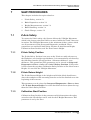
Safety Features
Our Systems are equipped with the following safety features. Look at them
and get to know them.
•
EMERGENCY STOP BUTTON: Pressing the red EMERGENCY
STOP BUTTON stops ALL activities in the System and cuts off power
to the System.
•
CIRCUIT BREAKER SWITCH: Operate the CIRCUIT BREAKER
SWITCH immediately if it becomes necessary to cut off power to the
System.
•
GROUNDING CABLES: Grounding Cables are attached to the inside
of each System Panel and must be disconnected each time a System
Panel is removed, and reconnected each time a System Panel is
replaced. An Electrostatic Discharge Device (ESD) should be worn
when handling the Grounding Cables.
•
INTERLOCK COVERS: Lock the Covers so they cannot be opened
during dicing.
•
Spindle Interlock
The Spindle Interlock prevents injury to the User by:
•
Preventing the Spindle Cover from opening while the Spindle
is rotating
•
Preventing the Axes from being moved while the Spindle
Cover is open
•
Stopping an Axis if the Spindle Cover is opened while the Axis
is moving
Any attempt to move an Axis while the Spindle Cover is open
results in an error message. An error message is also
P/N 97100-9002-000-14
Ver 06/05
v
Safety First
displayed if the Spindle Cover is opened while an Axis is
moving or when a bypass key is used. The Axes stop
immediately and the spindle keep moving mechanically.
The Spindle Interlock is automatically engaged while the
Dicer is initializing, and disengaged when initialization is
completed. In addition, the Spindle Interlock is disengaged
whenever the System is powered down. The Model 7100
cannot be powered down while the spindle is rotating.
During the Blade Change procedure, the Spindle Interlock
automatically disengages when the Spindle is turned off by
the System. At the end of the procedure, the Software reminds
the User to close the cover before clicking Finish. The Spindle
Interlock then re-engages automatically to protect the User
while the Dicer initializes. For more information about
changing the Blade, see Chapter 7.
Note: Once the Blade Change button is pressed, the Spindle Interlock is
unlocked and cover can be opened. The user has 20 seconds to open the
cover. If the cover has not been opened within 20 seconds, the interlock locks
back and can be bypassed by means of a key.
The Spindle Interlock can be locked and unlocked from the
Dicer screen in the Setup & Diagnostics workbook. Access
rights to this function can be restricted. For more information
about the Setup & Diagnostics workbook, see Chapter 2. For
more information about access rights and Access Levels, see
Chapter 4.
•
Load/Unload Interlock (7100EUR only)
The Load/Unload Interlock prevents the Load/Unload Cover from
being opened while the Model 7100 is operating. The Interlock is only
disengaged when Workpieces are loaded or unloaded from the Cutting
Chuck.
Unlike the Spindle Interlock, the Load/Unload Interlock is
automatically engaged after initialization. It disengages only after the
User initiates the Load procedure. X, Y and Theta Axes are initialized
when the procedure is completed.
During the Load procedure, another message appears after the
Workpiece has been accepted by the Cutting Chuck, reminding the
User to close the Load/Unload Cover before continuing. (This enables
the User to leave the cover open in cases where the Workpiece needs to
be manually held in place by the User before it can be accepted by the
Chuck.) An error message appears if the Load/Unload Cover is not
closed within a reasonable time by the User.
Advanced Dicing Technologies Ltd.
vi
ADT Model 7100 Semi-Automatic Dicing System Operations Manual
Safety First
The Load/Unload Interlock can be locked and unlocked from the Dicer
screen in the Setup & Diagnostics workbook. Access rights to this
function can be restricted. For more information about the Setup &
Diagnostics workbook, see Chapter 2. For more information about
access rights and Access Levels, see Chapter 4.
Note: Once the Unload button is pressed, the Load/Unload Interlock is
unlocked and cover can be opened. The user has 20 seconds to open the
cover. If the cover has not been opened within 20 seconds, the interlock locks
back and can be bypassed by means of a key.
P/N 97100-9002-000-14
Ver 06/05
vii
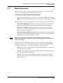
Before You Begin
BEFORE YOU BEGIN
This Manual
Before you begin to work with the 7100 Dicing Series machine, please read
this Manual. It explains how to work with the System, where and when to
perform operations, and why to do them.
Please be sure to read the section on Conventions. This section makes it
easier for you to perform procedures and understand concepts by
explaining the standards used in this Manual.
The Model 7100 Glossary, explains the technical terms used in describing
the System and System functions. Please use it as a reference tool while
working with the Manual.
Reading Chapter 3, System Operation, and Chapters 4 through 10 will give
you tools to perform the operation procedures.
Please read every procedure through to the end before starting the
procedure, whether it effects the System hardware or software. Thorough
understanding of what you are about to do will prevent unnecessary loss of
time due to confusion while you are performing the procedure.
Note: After Power On, and before normal operation, it is recommended to
warm up the system by running a simulated dicing session for thirty minutes.
The User should place a Workpiece on the Cutting Chuck, define and assign a
Recipe, and run simulated dicing for thirty minutes. The User must ensure that
the Cut Depth is set so that the Blade does not enter the Workpiece and no
Kerf Check or Cut Verification algorithm is selected. The spindle should rotate
at typical speed (the speed used for dicing) with cutting water on.
This simulated dicing, in the system steady state, warms up the Model 7100 to
prepare it for normal operation. Advanced Dicing Technologies Ltd. suggest
creating a warm-up recipe.
Advanced Dicing Technologies Ltd.
viii
ADT Model 7100 Semi-Automatic Dicing System Operations Manual
Contents at a Glance
Contents at a Glance
Chapter 1: Introduction
Chapter 2: System Description
Chapter 3: System Operation
Chapter 4: Administration
Chapter 5: Building Recipes
Chapter 6: Dicer Procedures
Chapter 7: Saw Procedures
Chapter 8: Special Features
Chapter 9: Configuration Options
Chapter 10: Troubleshooting
Appendices
Index
P/N 97100-9002-000-14
Ver 06/05
ix
Reference Documents
Reference Documents
•
ADT Model 7100 Semi-Automatic Dicing System Maintenance
Manual. It provides information and procedures to aid in the
performance of preventative maintenance, as well as troubleshooting
and repair procedures.
•
ADT Model 7100 Semi-Automatic Dicing System Large Area
Option
Advanced Dicing Technologies Ltd.
x
ADT Model 7100 Semi-Automatic Dicing System Operations Manual
Conventions
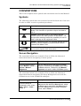
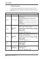
CONVENTIONS
This section explains basic symbols and conventions used in this Manual.
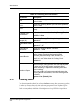
Symbols
The following symbols have been inserted on the left hand side of the text
in order to make it easier to perform procedures:
Symbol
Description
Note: Information given in a note describes how the
Model 7100 functions or provides a tip on how best to
use it.
Caution: Information given in a message labeled
caution refers to the safe operation of the Model 7100
and provides warnings where the possibility for loss of
data or damage to the equipment exists.
Danger: Information given in a message labeled danger
warns of possible hazard to personnel and extreme
hazard to the Model 7100.
A wrench indicates that a procedure deals with hardware
and requires physical User intervention.
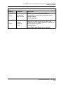
Screen Navigation
The convention below is an example of how to follow the shortened
instruction form for navigating to menu options.
Convention
Description
From the Manual menu,
select Manual > Dicer >
Vision > Manual
Alignment
Click the Manual menu and select the Dicer
submenu, followed by the Vision option within
the Dicer submenu, followed by the Manual
Alignment sub-option within the Vision option.
The convention below is an example of how to follow the shortened
instruction form for navigating the Setup & Diagnostics tree and the
Calibration tree in the Workbook workspace.
Convention
Description
From the Setup &
Diagnostics tree, select
Saw > Dicer > Axes >
Front Y
From the Setup & Diagnostics tree, select the
Saw branch and within the Saw branch, select
the Dicer branch and within the Dicer branch,
select the Axes branch and within the Axes
branch, select Front Y.
P/N 97100-9002-000-14 Ver 06/05
xi
ADT Model 7100 Semi-Automatic Dicing System Operations Manual
Abbreviations and Acronyms
A
Amps
BBD
Broken Blade Detector
gf
Grams of force
GUI
Graphical User Interface
Hz
Hertz (frequency)
in.
Inch
in. Hg
Inch of Mercury (vacuum pressure unit)
kgf*cm
Kilograms of force times lever length, in centimeters (torque
unit)
mil
0.001 inch
mm
Millimeter
MPU
Main Power Unit
ms
Millisecond
NCHD
Non-Contact Height Device
psi
Pounds per Square Inch
scfm
Standard Cubic Feet per Minute (gas flow unit)
UPS
Uninterruptible Power Supply
V
Volts
VAC
AC Voltage
VDC
DC Voltage
Advanced Dicing Technologies Ltd.
xii
ADT Model 7100 Semi-Automatic Dicing System Operations Manual
Table of Contents
TABLE OF CONTENTS
Safety First ______________________________________ iv
Before You Begin ________________________________ viii
Conventions _____________________________________ xi
Table of Contents ________________________________ xiii
List of Figures ___________________________________ xix
List of Tables __________________________________ xxv
1
2
3
INTRODUCTION ____________________________________ 1-1
1.1
Overview ____________________________________________ 1-1
1.2
Standard Features ____________________________________ 1-2
1.3
Modes of Operation ___________________________________ 1-2
1.4
Available Models _____________________________________ 1-3
1.5
Options _____________________________________________ 1-3
1.6
Available Models ____________________________________ 1.6-1
SYSTEM DESCRIPTION ______________________________ 2-1
2.1
Main Subsystems ___________________________________ 2.1-1
2.1.1
Front Panel _____________________________________________________2.1-1
2.1.2
Dicer __________________________________________________________2.1-4
2.1.3
Light Tower _____________________________________________________2.1-6
2.1.4
Un-Interruptible Power Supply ______________________________________2.1-8
2.2
Graphical User Interface ______________________________ 2.2-1
2.2.1
Menu Bar ______________________________________________________2.2-2
2.2.2
Toolbar ________________________________________________________2.2-5
2.2.3
Gauges ________________________________________________________2.2-8
2.2.4
Dicer Status Indicator _____________________________________________2.2-9
2.2.5
Active User Field _______________________________________________2.2-10
2.2.6
Activity Log ____________________________________________________2.2-10
2.2.7
Blade Indicator _________________________________________________2.2-10
2.2.8
Run Button_____________________________________________________2.2-11
2.2.9
Stop Button ____________________________________________________2.2-11
2.2.10
Workspaces ___________________________________________________2.2-12
2.3
System Configuration ________________________________ 2.3-1
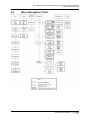
2.4
Menu Navigation Chart _______________________________ 2.4-1
SYSTEM OPERATION _______________________________ 3-1
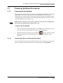
3.1
Powering Up/Down Procedures ________________________ 3.1-1
P/N 97100-9002-000-14
Ver 06/05
xiii
ADT Model 7100 Semi-Automatic Dicing System Operations Manual
Table of Contents
4
5
3.1.1
Powering Up the System __________________________________________3.1-1
3.1.2
Powering Down the System ________________________________________3.1-3
3.2
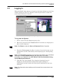
Logging In _________________________________________ 3.2-1
3.3
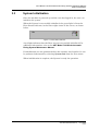
System Initialization _________________________________ 3.3-1
3.4
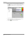
Defining the Job ____________________________________ 3.4-1
3.5
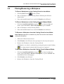
Placing/Removing a Workpiece ________________________ 3.5-1
3.6
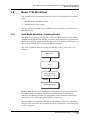
Model 7100 Workflows _______________________________ 3.6-1
3.6.1
Auto Mode Workflow - Existing Recipe _______________________________3.6-1
3.6.2
Auto Mode Workflow - New Recipe __________________________________3.6-3
3.6.3
Manual Mode Workflow ___________________________________________3.6-5
3.6.4
Procedures Included in the Workflows ________________________________3.6-5
3.7
Stopping System Operation ___________________________ 3.7-1
3.7.1
Emergency Stop _________________________________________________3.7-1
3.7.2
STOP/OFF Button and Soft Stop Button ______________________________3.7-1
3.7.3
Pausing a Process _______________________________________________3.7-2
3.7.4
Manual Stop ____________________________________________________3.7-2
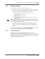
3.8
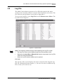
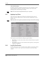
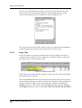
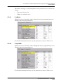
Log File ____________________________________________ 3.8-1
3.8.1
Applying Log Filters ______________________________________________3.8-2
3.8.2
Log File Find Feature _____________________________________________3.8-2
3.8.3
Exporting Log Files _______________________________________________3.8-3
3.8.4
Periodical backup ________________________________________________3.8-3
ADMINISTRATION __________________________________ 4-1
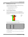
4.1
Access Levels ______________________________________ 4.1-1
4.2
Modifying Access Levels _____________________________ 4.2-1
4.2.1
Process Program Parameters ______________________________________4.2-1
4.2.2
User Interface Elements ___________________________________________4.2-2
4.2.3
Protected Mode _________________________________________________4.2-5
4.3
Adding and Removing Users __________________________ 4.3-1
4.3.1
Adding Users ___________________________________________________4.3-1
4.3.2
Removing Users _________________________________________________4.3-1
BUILDING RECIPES _________________________________ 5-1
5.1
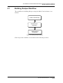
Building Recipes Workflow ___________________________ 5.1-1
5.2
Creating a New Recipe _______________________________ 5.2-1
5.3
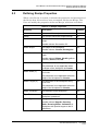
Defining Recipe Properties ____________________________ 5.3-1
5.3.1
Defining Blade Properties __________________________________________5.3-4
5.3.2
Displaying Blade Properties ________________________________________5.3-4
5.4
Specifying Recipe Parameters _________________________ 5.4-1
5.4.1
Accessing Parameters ____________________________________________5.4-1
Advanced Dicing Technologies Ltd.
xiv
ADT Model 7100 Semi-Automatic Dicing System Operations Manual
Table of Contents
6
5.4.2
Monitoring the Cutting Process _____________________________________5.4-4
5.4.3
General and Angle Parameters _____________________________________5.4-5
5.5
Importing and Exporting Recipes ______________________ 5.5-1
5.6
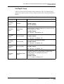
Recipe Templates ___________________________________ 5.6-1
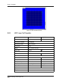
5.6.1
APC Standard Template ___________________________________________5.6-1
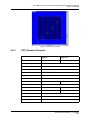
5.6.2
APC Loop Cut Template ___________________________________________5.6-2
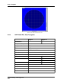
5.6.3
GPC Standard Template __________________________________________5.6-3
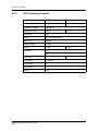
5.6.4
GPC Multi Die Size Template _______________________________________5.6-4
5.6.5
Standard Dressing Template _______________________________________5.6-5
5.6.6
GPC Dressing Template ___________________________________________5.6-6
DICER PROCEDURES _______________________________ 6-1
6.1
Workpiece Alignment ________________________________ 6.1-1
6.1.1
Manual Alignment ________________________________________________6.1-2
6.1.2
Auto Alignment __________________________________________________6.1-4
6.1.3
Teach Alignment _________________________________________________6.1-9
6.1.4
Choice of Cutting Angle by Panel ___________________________________6.1-19
6.1.5
Model Types ___________________________________________________6.1-22
6.1.6
Model Processing Filters _________________________________________6.1-23
6.1.7
Rotational Shrinkage ____________________________________________6.1-25
6.1.8
Average Index _________________________________________________6.1-26
6.1.9
Updating the Workpiece Alignment __________________________________6.1-28
6.2
Cut Verification _____________________________________ 6.2-1
6.2.1
Cut Verification: Special Search _____________________________________6.2-2
6.2.2
Auto Cut Verification ______________________________________________6.2-3
6.3
Kerf Checking ______________________________________ 6.3-1
6.3.1
Kerf Check Glossary ______________________________________________6.3-1
6.3.2
Standard Kerf Check Algorithm _____________________________________6.3-1
6.3.3
Kerf Check Workflow _____________________________________________6.3-2
6.3.4
Automatic Kerf Checking __________________________________________6.3-4
6.3.5
Manual Kerf Check _______________________________________________6.3-7
6.3.6
Teach Kerf Check ________________________________________________6.3-9
6.3.7
Kerf Check Options _____________________________________________6.3-13
6.4
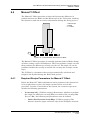
Manual Y Offset _____________________________________ 6.4-1
6.4.1
Required Recipe Parameters for Manual Y Offset _______________________6.4-1
6.4.2
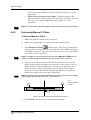
Performing Manual Y Offset ________________________________________6.4-2
6.4.3
Y-Offset Reference Positions _______________________________________6.4-3
6.4.4
Y-Offset on Dress Block ___________________________________________6.4-3
6.5
Special Cut Procedures ______________________________ 6.5-1
6.5.1
Partial Wafer Cut ________________________________________________6.5-1
6.5.2
Sub-Index ______________________________________________________6.5-1
6.5.3
Loop Cut _______________________________________________________6.5-2
P/N 97100-9002-000-14
Ver 06/05
xv
ADT Model 7100 Semi-Automatic Dicing System Operations Manual
Table of Contents
7
8
6.5.4
Chopping ______________________________________________________6.5-4
6.5.5
Multi-Panel Alignment _____________________________________________6.5-4
6.5.6
Cut Depth Compensation _________________________________________6.5-11
6.5.7
Negative Index _________________________________________________6.5-11
SAW PROCEDURES _________________________________ 7-1
7.1
Z-Axis Safety _______________________________________ 7.1-1
7.1.1
Z-Axis Safety Position ____________________________________________7.1-1
7.1.2
Z-Axis Return Height _____________________________________________7.1-1
7.1.3
Calibration Start Position __________________________________________7.1-1
7.1.4
Pre Non Contact Height ___________________________________________7.1-2
7.2
Blade Expansion ____________________________________ 7.2-1
7.3
Height Procedures ___________________________________ 7.3-1
7.3.1
Height Reference Device __________________________________________7.3-3
7.3.2
Chuck Height ___________________________________________________7.3-5
7.3.3
Chuck to Height Device Delta Measurement ___________________________7.3-5
7.3.4
Sample Blade Calibration __________________________________________7.3-6
7.3.5
Auto Height Compensation _________________________________________7.3-7
7.4
Blade Handling _____________________________________ 7.4-1
7.4.1
Blade Information ________________________________________________7.4-1
7.4.2
Blade Replacement (Change) ______________________________________7.4-7
7.4.3
Blade Dressing _________________________________________________7.4-15
7.5
Chuck Change ______________________________________ 7.5-1
7.5.1
Replacing the Chuck _____________________________________________7.5-1
7.5.2
Reteaching the Focus on the Chuck _________________________________7.5-3
SPECIAL FEATURES ________________________________ 8-1
8.1
Load Monitoring ____________________________________ 8.1-1
8.1.1
Load Monitoring with DC or AC Spindle _______________________________8.1-1
8.1.2
Online Monitoring ________________________________________________8.1-1
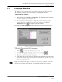
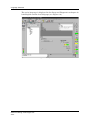
8.2
Language Selection __________________________________ 8.2-1
8.3
Wafer Vacuum Check ________________________________ 8.3-1
8.4
Open Loop Theta Accuracy Procedures _________________ 8.4-1
8.4.1
Stress Release __________________________________________________8.4-1
8.4.2
Theta Motion Replay _____________________________________________8.4-2
8.5
Spindle Velocity _____________________________________ 8.5-1
8.5.1
Reduced Height Velocity __________________________________________8.5-1
8.5.2
Reduced Vision Spindle Velocity ____________________________________8.5-2
8.6
Focus Change (Initial Focus Position) __________________ 8.6-1
8.7
Manual Inspection Illumination ________________________ 8.7-1
Advanced Dicing Technologies Ltd.
xvi
ADT Model 7100 Semi-Automatic Dicing System Operations Manual
Table of Contents
9
10
8.8
Database Backup ____________________________________ 8.8-1
8.9
Theta Safety Limits on X-Axis _________________________ 8.9-1
8.10
Change of Length Unit Type __________________________ 8.10-1
8.11
Multi-Panel Bar Code _______________________________ 8.11-1
8.11.1
Activating the Bar Code Feature ___________________________________8.11-1
8.11.2
Using the Bar Code Reader _______________________________________8.11-2
CONFIGURATION OPTIONS __________________________ 9-1
9.1
Autoloader _________________________________________ 9.1-1
9.1.1
Autoloader Description ____________________________________________9.1-1
9.1.2
Autoloader User Interface __________________________________________9.1-3
9.1.3
Autoloader Operation ____________________________________________9.1-12
9.2
Tilted Spindle _______________________________________ 9.2-1
9.2.1
Changing the Spindle Angle in a Recipe ______________________________9.2-2
9.2.2
Height Procedure Changes ________________________________________9.2-2
9.2.3
Changing the Spindle Angle ________________________________________9.2-3
9.2.4
Mechanical Adjustments ___________________________________________9.2-7
9.3
Dress Station _______________________________________ 9.3-1
9.3.1
Configuring the Dress Station _______________________________________9.3-1
9.3.2
Teaching the Dress Station ________________________________________9.3-2
9.3.3
Dress Station Setup ______________________________________________9.3-5
9.3.4
Dressing Modes _________________________________________________9.3-6
9.4
Wash Pipe _________________________________________ 9.4-1
9.4.1
Manual Operation ________________________________________________9.4-3
9.4.2
Model 7100 Vectus and ProVectus __________________________________9.4-4
9.4.3
Model 7100 Fortis and ProFortis ____________________________________9.4-5
TROUBLESHOOTING _______________________________ 10-1
10.1
Error Message Information ___________________________ 10.1-1
10.2
Recipe Problems ___________________________________ 10.2-1
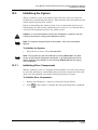
10.3
Initializing the System _______________________________ 10.3-1
10.3.1
Initializing Dicer Components ______________________________________10.3-1
10.4
Height Problem ____________________________________ 10.4-1
10.5
Database Restoration and PC Recovery ________________ 10.5-1
10.6
Camera Installation After Emergency Stop ______________ 10.6-1
10.7
If Nothing Helps ____________________________________ 10.7-1
10.7.1
KMI and Database ______________________________________________10.7-1
10.8
UPS Bypass _______________________________________ 10.8-1
P/N 97100-9002-000-14
Ver 06/05
xvii
ADT Model 7100 Semi-Automatic Dicing System Operations Manual
Table of Contents
Appendices ____________________________________________ A-1
The Model 7100 Glossary _____________________________________ A-1
Algorithms _________________________________________________ A-8
Cut Algorithms _______________________________________________________ A-8
Align Algorithms ______________________________________________________ A-9
Kerf Check Algorithm _________________________________________________ A-10
Bright Kerf Algorithm _________________________________________________ A-10
Full Teach Alignment Algorithm _________________________________________ A-10
Kerf Check Teach Algorithm ___________________________________________ A-11
Recipe Parameters __________________________________________ A-12
Air Parameters ______________________________________________________ A-12
Align Parameters ____________________________________________________ A-13
Align Kerf Model Parameters ___________________________________________ A-18
Auto Height Compensation ____________________________________________ A-19
Average Index Parameters ____________________________________________ A-20
Bar Code Parameters ________________________________________________ A-21
Blade Parameters ___________________________________________________ A-22
Cut Depth Comp ____________________________________________________ A-23
Cut Parameters _____________________________________________________ A-24
Cut Verify Parameters ________________________________________________ A-28
Cut Verify Limit Parameters ____________________________________________ A-30
Diagnostisc Parameters _______________________________________________ A-31
Dressing Parameters _________________________________________________ A-31
Dress Block Parameters ______________________________________________ A-32
Height Parameters ___________________________________________________ A-34
Kerf Check Parameters _______________________________________________ A-35
Kerf Check Limit Parameters ___________________________________________ A-37
Load Monitor Cutting Parameters _______________________________________ A-39
Load Monitor Baseline ________________________________________________ A-39
Loop Cut Parameters _________________________________________________ A-40
Manual Inspection Parameters _________________________________________ A-40
Model Precessing Parameters __________________________________________ A-42
MHS Parameters ____________________________________________________ A-43
Multi-Panel Parameters _______________________________________________ A-43
Override Parameters _________________________________________________ A-43
Shrinkage Parameters ________________________________________________ A-44
Teach Center Parameters _____________________________________________ A-46
Tilted Spindle Parameters _____________________________________________ A-47
Wash Pipe Parameters _______________________________________________ A-47
Y Offset Parameters __________________________________________________ A-48
Index ______________________________________ Index-i
Advanced Dicing Technologies Ltd.
xviii
ADT Model 7100 Semi-Automatic Dicing System Operations Manual
List of Figures
LIST OF FIGURES
Figure 1-1:
Figure 2-1:
Figure 2-2:
Figure 2-3:
Figure 2-4:
Figure 2-5:
Figure 2-6:
Figure 2-7:
Figure 2-8:
Figure 2-9:
Figure 2-10:
Figure 2-11:
Model 7100 ProVectus __________________________________ 1-1
Model 7100 External Parts at a Glance_____________________ 2-1
Model 7100 Series Front Panel __________________________ 2.1-1
Stop Button Parameters _______________________________ 2.1-3
Dicer _______________________________________________ 2.1-4
Vision System________________________________________ 2.1-5
Illumination Accessories Attached to the Microscope_______ 2.1-6
Buzzer in Light Tower _________________________________ 2.1-7
Enabling the Digital I/O PCB ____________________________ 2.1-8
UPS ________________________________________________ 2.1-8
Model 7100 Series Opening Screen ______________________ 2.2-1
Help/About Screen ____________________________________ 2.2-5
Figure 2-12:
Figure 2-13:
Figure 2-14:
Figure 2-15:
Figure 2-16:
Figure 2-17:
Figure 2-18:
Figure 2-19:
Figure 2-20:
Figure 2-21:
Figure 2-22:
Figure 2-23:
Figure 2-24:
Figure 2-25:
Figure 2-26:
Figure 3:
Figure 4:
Dicer Status Indicator _________________________________ 2.2-9
Activity Log_________________________________________ 2.2-10
Stop Button Parameters ______________________________ 2.2-12
Workspace Buttons __________________________________ 2.2-13
Main Workspace _____________________________________ 2.2-14
Top View Area_______________________________________ 2.2-15
Top View Popup Menu ________________________________ 2.2-15
Load Monitor Graph __________________________________ 2.2-16
Side View Area ______________________________________ 2.2-17
Dicing from the Side View _____________________________ 2.2-17
Video Workspace ____________________________________ 2.2-18
FOV Display Guides __________________________________ 2.2-19
Zeroed Axis Buttons _________________________________ 2.2-21
Zoom Option Configured______________________________ 2.2-23
Zoom Controls ______________________________________ 2.2-24
Enabling Digital Magnification _________________________ 2.2-24
Using Digital Magnification ____________________________ 2.2-25
Figure 2-1:
Figure 2-2:
Figure 2-3:
Figure 2-4:
Figure 2-5:
Figure 2-6:
Figure 2-7:
Wizard Tab _________________________________________ 2.2-26
Model Tab __________________________________________ 2.2-27
Main Workspace Window in Video Workspace ____________ 2.2-28
Programming Workspace _____________________________ 2.2-29
Recipe Parameters ___________________________________ 2.2-30
Setup & Diagnostics Workbook ________________________ 2.2-31
Overflow Sensor Indication____________________________ 2.2-32
P/N 97100-9002-000-14
Ver 06/05
xix
ADT Model 7100 Semi-Automatic Dicing System Operations Manual
List of Figures
Figure 2-8:
Figure 2-9:
Figure 2-10:
Figure 2-11:
Figure 2-12:
Figure 2-13:
Figure 2-14:
Figure 2-15:
Figure 3-1:
Figure 3-2:
Figure 3-3:
Figure 3-4:
Figure 3-5:
Figure 3-6:
Figure 3-7:
Figure 3-8:
Figure 4-9:
Figure 4-10:
Figure 4-11:
Figure 4-12:
Figure 4-13:
Figure 4-14:
Figure 4-15:
Figure 4-16:
Figure 5-1:
Figure 5-2:
Water Overflow Message______________________________ 2.2-32
Calibration Workbook ________________________________ 2.2-33
Calibration Workbook: Sensor Calibration _______________ 2.2-34
Load Monitor Workspace _____________________________ 2.2-35
Dressing Workspace _________________________________ 2.2-36
Override Workspace _________________________________ 2.2-36
Blade Info Screen ____________________________________ 2.2-37
Configuration Dialog Box ______________________________ 2.3-1
Database Restore dialog window ________________________ 3.1-2
Login Dialog Box _____________________________________ 3.2-1
Dicer Status Indicator _________________________________ 3.3-1
Job Dialog Box _______________________________________ 3.4-1
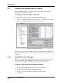
Assigning Recipe from Saw Screen ______________________ 3.4-2
Emergency Stop Button _______________________________ 3.7-1
Log File Viewer _______________________________________ 3.8-1
Log File Filter Configuration ____________________________ 3.8-2
Access Rights Columns _______________________________ 4.2-1
Access Rights Bar ____________________________________ 4.2-2
Extending Access Rights ______________________________ 4.2-2
Access Rights Bar ____________________________________ 4.2-4
Access Rights to Parameter Buttons _____________________ 4.2-4
Protection Access Rights Bar___________________________ 4.2-5
Access Rights to Unprotected Mode _____________________ 4.2-6
User Manager Dialog Box ______________________________ 4.3-1
Groups and Recipes in Tree Display)______________________ 5-1
Building Recipes Workflow _____________________________ 5.1-1
Figure 5-3:
Figure 5-4:
Figure 5-5:
Figure 5-6:
Figure 5-7:
Figure 5-8:
Figure 5-9:
Figure 5-10:
Figure 5-11:
Figure 5-12:
Figure 5-13:
Duplicate Recipe Dialog Box____________________________ 5.2-1
Recipe Properties_____________________________________ 5.3-3
Missing Parameters Report_____________________________ 5.3-3
Blade Properties (2" Hub Blade)_________________________ 5.3-4
Blade Selection List ___________________________________ 5.3-6
Blade Properties______________________________________ 5.3-6
Duplicate Blade Dialog Box_____________________________ 5.3-7
Delete Blade Message _________________________________ 5.3-8
Parameter Categories in the Programming Tree____________ 5.4-1
Recipe Parameters ____________________________________ 5.4-4
Workpiece with Two Defined Angles _____________________ 5.4-5
Advanced Dicing Technologies Ltd.
xx
ADT Model 7100 Semi-Automatic Dicing System Operations Manual
List of Figures
Figure 5-14:
Figure 5-15:
Figure 5-16:
Figure 5-17:
Figure 5-18:
Figure 5-19:
Figure 5-20:
Figure 5-21:
Figure 5-22:
Figure 5-23:
Figure 5-24:
Figure 5-25:
Figure 5-26:
Figure 5-27:
Figure 6-1:
Figure 6-2:
Figure 6-3:
Figure 6-4:
Figure 6-5:
Figure 6-6:
Figure 6-7:
Figure 6-8:
Figure 6-9:
Figure 6-10:
Figure 6-11:
Figure 6-12:
Angle Tab Popup Menu ________________________________ 5.4-6
PP Insert Dialog Box __________________________________ 5.4-6
Angle Tab Added _____________________________________ 5.4-6
PP Move Dialog Box___________________________________ 5.4-7
Moving an Angle Tab __________________________________ 5.4-7
PP Change Dialog Box_________________________________ 5.4-8
Parameter Category List _______________________________ 5.4-9
Parameter List _______________________________________ 5.4-9
Recipe Export Dialog Box ______________________________ 5.5-1
Recipe Import Dialog Box ______________________________ 5.5-2
APC Standard Cut Map ________________________________ 5.6-2
APC Loop Cut Map____________________________________ 5.6-3
GPC Standard Cut Map ________________________________ 5.6-4
GPC Multi-Die Size Cut Map ____________________________ 5.6-5
Workpiece Before and After Alignment ___________________ 6.1-1
Aligning the Reticle ___________________________________ 6.1-3
Sample Cut Position __________________________________ 6.1-4
Index _______________________________________________ 6.1-5
Teach Parameter Button Enabled________________________ 6.1-6
Teach Alignment Process Message Box __________________ 6.1-6
Teach Index Process Dialog Box ________________________ 6.1-7
Update Parameters Dialog Box__________________________ 6.1-8
Copy From Angle - Enhancement Parameters ____________ 6.1-11
Selecting an Align Type_______________________________ 6.1-12
Teach Alignment Opening Wizard ______________________ 6.1-13
Spiral Search _______________________________________ 6.1-15
Figure 6-13:
Figure 6-14:
Figure 6-15:
Figure 6-16:
Figure 6-17:
Figure 6-18:
Figure 6-19:
Figure 6-20:
Figure 6-21:
Figure 6-22:
Figure 6-23:
Directional Search ___________________________________ 6.1-15
Main Model Search___________________________________ 6.1-16
Alignment Algorithm _________________________________ 6.1-17
Conceptual Cutting by Angle diagram ___________________ 6.1-20
Multi-Panel Teach Screen _____________________________ 6.1-21
Multi angles View ____________________________________ 6.1-21
Model Options ______________________________________ 6.1-23
Model Processing Filter Parameters ____________________ 6.1-25
Rotational Shrinkage Parameters_______________________ 6.1-26
Average Index Parameters ____________________________ 6.1-27
Kerf Check Glossary __________________________________ 6.3-1
P/N 97100-9002-000-14
Ver 06/05
xxi
ADT Model 7100 Semi-Automatic Dicing System Operations Manual
List of Figures
Figure 6-24:
Figure 6-25:
Figure 6-26:
Figure 6-27:
Figure 6-28:
Figure 6-29:
Figure 6-30:
Figure 6-31:
Figure 6-32:
Figure 6-33:
Figure 6-34:
Figure 6-35:
Figure 6-36:
Figure 6-37:
Figure 6-38:
Figure 6-39:
Figure 6-40:
Figure 6-41:
Figure 6-42:
Figure 6-43:
Figure 7-1:
Figure 7-2:
Figure 7-3:
Figure 7-4:
Figure 7-5:
Figure 7-6:
Kerf Check Workflow __________________________________ 6.3-4
Kerf Check Measurements _____________________________ 6.3-5
Main Workspace Window Showing Kerf Check Results _____ 6.3-6
Model Tab Kerf Check Results __________________________ 6.3-6
Manual Kerf Check Screen _____________________________ 6.3-8
Cut Depth Compensation value list ______________________ 6.3-9
Reference Position Options ___________________________ 6.3-10
Pattern: “Kerf Up” with Reference Position: “Lower Edge” _ 6.3-11
Teach Kerf Check ____________________________________ 6.3-12
Two-step Kerf Check Parameter Table___________________ 6.3-14
Kerf Check Algorithm Options _________________________ 6.3-15
Y Offset Between Microscope and Blade__________________ 6.4-1
Manual Y Offset: Positioning the Microscope ______________ 6.4-2
Y-Offset Reference Position ____________________________ 6.4-3
Loop Cut Screen______________________________________ 6.5-2
Loop Cut Map ________________________________________ 6.5-4
The Align Lines_______________________________________ 6.5-6
Wizard - Model Not Found ______________________________ 6.5-8
Multi-Panel Angle Tabs ________________________________ 6.5-8
Removing Links ______________________________________ 6.5-9
Height Procedure _____________________________________ 7.3-1
Button Height Procedure Tools in GUI____________________ 7.3-2
Non-Contact Height Procedure Tools in GUI_______________ 7.3-3
Height Devices _______________________________________ 7.3-3
Auto Height Compensation _____________________________ 7.3-7
Blade Information Screen ______________________________ 7.4-1
Figure 7-7:
Figure 7-8:
Figure 7-9:
Figure 7-10:
Figure 7-11:
Figure 7-12:
Figure 7-13:
Figure 7-14:
Figure 7-15:
Figure 7-16:
Figure 7-17:
Blade Exposure Chart _________________________________ 7.4-2
Wear Rate Chart ______________________________________ 7.4-4
Blade Change Tab (2" and 4" Systems without BBD) _______ 7.4-5
Blade Change Tab (2" Systems with BBD) ________________ 7.4-5
Blade Type Tab (Hub Blade) ____________________________ 7.4-6
Blade Type Tab (Hubless Blade)_________________________ 7.4-6
Blade Status Tab _____________________________________ 7.4-6
4" Blade Removing Tool _______________________________ 7.4-9
Full Blade Handling Toolkit for 2" Spindle _______________ 7.4-10
Define Blade Screen__________________________________ 7.4-11
2" Spindle with Cooling Block _________________________ 7.4-11
Advanced Dicing Technologies Ltd.
xxii
ADT Model 7100 Semi-Automatic Dicing System Operations Manual
List of Figures
Figure 7-18:
Figure 7-19:
Figure 7-20:
Figure 7-21:
Figure 7-22:
Figure 8-1:
Figure 8-2:
Figure 8-3:
Figure 8-4:
Figure 8-5:
Figure 8-6:
Figure 8-7:
Figure 8-8:
Figure 8-9:
Figure 8-10:
Figure 8-11:
Figure 8-12:
Figure 8-13:
Figure 8-14:
Figure 8-15:
Figure 8-16:
Figure 9-1:
Figure 9-2:
Figure 9-3:
Figure 9-4:
Figure 9-5:
4" Spindle with Cooling Block _________________________ 7.4-12
2" Blade Holder _____________________________________ 7.4-13
Tuning the BBD _____________________________________ 7.4-14
Override Steps Screen________________________________ 7.4-19
Dressing Screen _____________________________________ 7.4-22
Load Monitor Workspace During Cutting _________________ 8.1-2
Display and Hide Lines Popup Menu (Top Graph) __________ 8.1-3
Display and Hide Lines Popup Menu (Bottom) _____________ 8.1-3
Control Screen _______________________________________ 8.1-5
Language Local Selection Screen _______________________ 8.2-1
Simplified Chinese GUI ________________________________ 8.2-2
Theta Align Stress Disabled ____________________________ 8.4-2
Theta Align Stress Enabled_____________________________ 8.4-2
Automatic Backup Enabled_____________________________ 8.8-1
Backup Drop-Down List________________________________ 8.8-2
Dicer Tree ___________________________________________ 8.9-1
Right X Limit _________________________________________ 8.9-2
Left X Limit __________________________________________ 8.9-2
Activating the Bar Code Reader ________________________ 8.11-1
Bar Code Dialog Box _________________________________ 8.11-2
Bar Code Validation Failed ____________________________ 8.11-2
Model 7100 with Autoloader ____________________________ 9.1-1
Autoloader Features in the Model 7100 User Interface ______ 9.1-3
CassComp Workbook _________________________________ 9.1-5
Elevator Screen ______________________________________ 9.1-6
Finger Screen ________________________________________ 9.1-8
Figure 9-6:
Figure 9-7:
Figure 9-8:
Figure 9-9:
Figure 9-10:
Figure 9-11:
Figure 9-12:
Figure 9-13:
Figure 9-14:
Figure 9-15:
Figure 9-16:
CassComp > Cassette1 Workbook_______________________ 9.1-9
MHS General Screen _________________________________ 9.1-10
MHS Axes Screen____________________________________ 9.1-11
Main Load Screen____________________________________ 9.1-13
Main Unload Screen __________________________________ 9.1-13
Manual Load Screen _________________________________ 9.1-14
Manual Unload Screen________________________________ 9.1-14
Configuration Screen_________________________________ 9.1-16
Tilted Spindle ________________________________________ 9.2-1
Programming Screen __________________________________ 9.2-2
Setup Screen ________________________________________ 9.2-4
P/N 97100-9002-000-14
Ver 06/05
xxiii
ADT Model 7100 Semi-Automatic Dicing System Operations Manual
List of Figures
Figure 9-17:
Figure 9-18:
Figure 9-19:
Figure 9-20:
Figure 9-21:
Figure 9-22:
Figure 9-23:
Figure 9-24:
Figure 9-25:
Figure 9-26:
Figure 9-27:
Figure 9-28:
Figure 9-29:
Figure 9-30:
Figure 9-31:
Figure 9-32:
Figure 10-1:
Figure 10-2:
Figure 10-3:
Figure 10-4:
Figure 10-5:
Figure A-1:
Spindle Holding Screws _______________________________ 9.2-5
Camera Holding Screws _______________________________ 9.2-5
Error Message _______________________________________ 9.2-6
Dress Station ________________________________________ 9.3-1
Dress Station Screen __________________________________ 9.3-3
Replacing the Dressing Block___________________________ 9.3-4
Dressing Cut Map Animation ___________________________ 9.3-8
Dress Block Change Wizard ____________________________ 9.3-8
Wash Pipe ___________________________________________ 9.4-1
Wash Pipe Feature Schematic Diagram___________________ 9.4-1
Wash Pipe Setup and Diagnostic Parameters______________ 9.4-2
Stop and Pause Wash Pipe Operation ____________________ 9.4-3
Wash Pipe Activation Icon _____________________________ 9.4-4
Spray/Wash Indicator__________________________________ 9.4-4
No Water Flow Indicator _______________________________ 9.4-5
Wash Pipe Water Flow Indicator_________________________ 9.4-5
Sample Error Messages________________________________ 10-2
Subsystem Initialization Screen _________________________ 10-2
Stopping the 7100 Software ____________________________ 10-1
Stopping the PowerMon II ______________________________ 10-2
Changing the Startup Type _____________________________ 10-3
Velocity of X-Axis _____________________________________ A-28
Advanced Dicing Technologies Ltd.
xxiv
ADT Model 7100 Semi-Automatic Dicing System Operations Manual
List of Tables
LIST OF TABLES
Table 6-1:
Table 2-1:
Table 4-1:
Table 4-2:
Table 5-1:
Table 5-2:
Table 5-3:
Table 6-1:
Table 6-2:
Table 7-1:
Table 7-2:
Table 7-3:
Available Models of the 7100 Dicing Series ______________ 1.6-1
Light Tower States __________________________________ 2.1-6
Access Rights Color Codes __________________________ 4.2-1
User Interface Elements Access Color Codes ____________ 4.2-4
Recipe Properties ___________________________________ 5.3-1
Blade Properties ____________________________________ 5.3-5
Parameter Categories _______________________________ 5.4-2
APC Loop Cut Parameters ____________________________ 6.5-3
Multi-Panel Cutting Sequences _______________________ 6.5-10
Dressing vs. Override ______________________________ 7.4-16
Override Parameters _______________________________ 7.4-18
Dressing Parameters _______________________________ 7.4-20
Table 8-1:
Table 8-2:
Table 9-1:
Table A-1:
Table A-2:
Table A-3:
Table A-4:
Table A-5:
Table A-6:
Table A-7:
Table A-8:
Table A-9:
Table A-10:
Table A-11:
Table A-12:
Table A-13:
Table A-14:
Parameters for Cutting _______________________________ 8.1-4
Baseline Parameters ________________________________ 8.1-4
Dressing Block Parameters ___________________________ 9.3-6
Air Parameters _____________________________________ A-12
Align Parameters ___________________________________ A-13
Align Keft Model Parameters __________________________ A-18
Auto Height Compensation Parameters _________________ A-19
Average Index Parameters ___________________________ A-20
Bar Code Reader Parameters _________________________ A-21
Blade Parameters ___________________________________ A-22
Cut Depth Comp Parameters __________________________ A-23
Cut Parameters _____________________________________ A-24
Cut Verify Parameters _______________________________ A-28
Cut Verify Limit Parameters __________________________ A-30
Dressing Parameters ________________________________ A-31
Dressing Parameters ________________________________ A-31
Dress Block Parameters _____________________________ A-32
Table A-15:
Table A-16:
Table A-17:
Table A-18:
Table A-19:
Table A-20:
Table A-21:
Height Parameters __________________________________
Kerf Check Parameters ______________________________
Kerf Check Limit Parameters _________________________
Load Monitor Cutting Parameters ______________________
Load Monitor Baseline Parameters ____________________
Loop Cut Parameters ________________________________
Manual Inspection Parameters ________________________
P/N 97100-9002-000-14
A-34
A-35
A-37
A-39
A-39
A-40
A-40
Ver 06/05
xxv
K&S Model 7100 Semi-Automatic Dicing System Operations Manual
List of Tables
Table A-22:
Table A-23:
Table A-24:
Table A-25:
Table A-26:
Table A-27:
Table A-28:
Table A-29:
Table A-30:
Model Processing Parameters ________________________
MHS Parameters ____________________________________
Material Handling System Parameters __________________
Override Parameters ________________________________
Shrinkage Parameters _______________________________
Teach Center _______________________________________
Tilted Spindle Parameters ____________________________
Wash Pipe Parameters _______________________________
Y Offset Parameters _________________________________
Advanced Dicing Technologies Ltd.
xxvi
A-42
A-43
A-43
A-43
A-44
A-46
A-47
A-47
A-48
ADT Model 7100 Semi-Automatic Dicing System Operations Manual
1
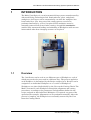
INTRODUCTION
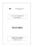
The Model 7100 Series is a semi-automatic dicing system, manufactured by
Advanced Dicing Technologies Ltd. Semiconductor, glass, and plastic
workpieces of all types can be automatically cut after the workpiece has
been loaded by a user. Any part of the cutting process can also be
performed manually by a user, if required. Each workpiece must be
manually removed and cleaned after cutting. An optional autoloader
enables fully automated loading and unloading of Workpieces with no user
intervention other than changing cassettes as required.
Figure 1-1: Model 7100 ProVectus
1.1
Overview
The 7100 Series can be used to cut different types of Workpieces, each of
which may need to be processed in a different way. The process applied to
each Workpiece is determined by the Recipe assigned to it. Recipes can be
assigned to an individual Workpiece or to a series of Workpieces.
Workpieces are placed individually by the User on the Cutting Chuck. The
Model 7100 moves each Workpiece through the alignment and cutting
procedures, according to the parameters and algorithms defined in the
recipe assigned to that individual Workpiece. If required, any part of the
operation (for example, Alignment) can be performed manually. After the
process is complete, the Workpieces are manually removed by the User
from the Cutting Chuck.
P/N 97100-9002-000-14
Ver 06/05
1-1
Introduction
1.2
Standard Features
The Model 7100 Series includes the following features:
1.3
•
Single Head dicing machine
•
Single Magnification Vision System
•
Kerf Check Monitoring
•
Brushless Spindle:
•
DC, 60,000 RPM, speed controlled Front Mount Air Bearing
2" Spindle (7100 Vectus and 7100 ProVectus)
•
AC, 30,000 RPM, speed controlled Air Bearing 4" Spindle
(7100 Fortis)
•
DC, 30,000 RPM, speed controlled Air Bearing 4" Spindle
(7100 ProFortis)
•
Quick-Change Chucks that hold Workpieces in place using vacuum
suction
•
Load Monitoring: enables the User to measure the load on the
Spindle (measured in Amps) caused by resistance encountered by the
blade during operation.
•
Daily Database Backup
•
Water Cleaning Jets: enables additional cleaning of the Workpiece.
•
Un-Interruptible Power Supply (UPS) for the PC - used in case of
an emergency stop to prevent abnormal computer shut down.
Modes of Operation
The Model 7100 Series is operable as follows:
•
Auto Mode: Requires no User intervention once Run is clicked.
Workpieces commonly used in the Customer’s System are processed in
Auto mode. The entire process, including Alignment, dicing, Kerf
Checking and getting to the Unload station after the process is
finished, is completely automatic.
•
Manual Mode: This mode is used for dicing Workpieces that are
difficult to process automatically, for example:
•
Damaged or partial Workpieces
•
Workpieces that are difficult to align automatically
•
Partially cut Workpieces
•
After the process is finished, the user needs to click the Unload
button to remove the workpiece from the dicer.
Advanced Dicing Technologies Ltd.
1-2
ADT Model 7100 Semi-Automatic Dicing System Operations Manual
•
1.4
Exhibition Mode: This mode is intended for exhibition use and
allows to operate the System without connecting to a water supply. For
more information, refer to Appendix 5, "Exhibition Mode" of the
Maintenance Manual.
Available Models
The 7100 Series includes four models:
•
4" Fortis - 4" AC Spindle with Cable Type Turntable
•
4" Pro Fortis - 4" DC Spindle with Closed Loot Theta
•
Vectus - 2" DC Spindle with Open Loop Theta
•
Pro Vectus - 2" DC Spindle with Closed Loop Theta
Note: For detailed hardware configurations refer to section 1.6
1.5
Options
The Model 7100 can include one or more of the following options:
•
Autoloader: enables automatic loading and unloading of workpieces
from cassettes.
•
Multi-Language Interface: enables the GUI to switch between
English and the local language. For more information about currently
supported languages, refer to the latest Release Note.
•
Tilted Spindle: This option enables the System to cut wafers at any
angle that falls between 0 and 15 degrees by changing the orientation
of the Spindle and the Microscope. Systems that include the Tilted
Spindle option, are delivered pre-configured with all the settings
necessary for cutting at both standard and tilted orientation.
•
DC brushless, 30,000 RPM speed-controlled 4" Air Bearing Spindle
•
Magnification: x30 (Pro Vectus and Pro Fortis only), x60, x120
(standard), x240.
•
High Accuracy Theta Axis
•
Dress Station - intended to periodically reshape and/or clean the
cutting blade in order to enhance the Kerf quality, without
interrupting the cutting process.
•
Broken Blade Detector (BBD) - Optional for 7100 Vectus and 7100
ProVectus (2")
•
Wash Pipe - used in addition to the spray bars for washing during the
dicing process.
P/N 97100-9002-000-14
Ver 06/05
1-3
Introduction
Advanced Dicing Technologies Ltd.
1-4
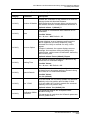
1.6
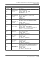
Vectus (2")
Standard
NA
NA
Standard
NA
NA
Commercial
Window
Standard
Optional
Standard
NA
Standard
Standard
Standard
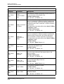
Models/ Features
2" DC Spindle
4" AC Spindle
4" DC Spindle
Open Loop Theta Table
Closed Loop Theta Table
Closed Loop Theta Table (high
accuracy)
Digital Camera
Covers
Non-Contact Height Device (NCHD)
Mechanical Height Button
2"/ 3"Cooling Block
4"/ 5”Cooling Block
Three-Flow Cooling Control
Cleaning Jets
Spray Bars
Standard
Standard
Standard
NA
Standard
Optional
Standard
Transparent
Industrial
Optional
Standard
NA
NA
NA
Standard
ProVectus (2")
NA
NA
Standard
Standard
Standard
NA
Standard
Optional
Transparent
Industrial
Optional
Standard
NA
Standard
NA
NA
ProFortis (4")
P/N 97100-9002-000-14 Ver 06/05
1.6-1
Standard
Standard
Standard
NA
Standard
Optional
Window
Commercial
NA
NA
Standard
NA
Standard
NA
Fortis (4")
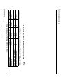
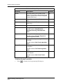
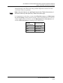
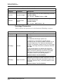
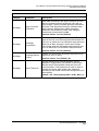
Table 6-1: Available Models of the 7100 Dicing Series
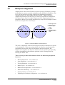
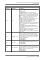
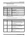
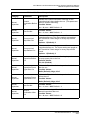
Several configurations of the 7100 Series are available, each offering different features and options, as described
in Table 6-1.
Available Models
ADT Model 7100 Semi-Automatic Dicing System Operations Manual
Available Models
NA
Standard
Standard
Standard
Standard
Standard
N/A
Optional
Standard
Optional
Standard
Optional
Optional
Optional
Optional
Optional
High Cooling
Water Separator
Venturi Vacuum Pump
Y Axis Linear Encoder
Vacuum Sensor
High Definition Vision System with
x120 Magnification
Vision Magnification x30
Vision Magnification x60, x240
Pattern Recognition System (PRS)
with Vertical and Oblique LED
Illumination
Pattern Recognition System (PRS)
with Vertical and Oblique (Ring)
Halogen Illumination
Load Monitor
Chuck Frame Adapter
Quick-Change Cutting Chuck
Broken Blade Detector (BBD)
Light Tower
Air Purification Kit
Advanced Dicing Technologies Ltd.
1.6-2
Vectus (2")
Models/ Features
Optional
Optional
Optional
Optional
Optional
Standard
Optional
Standard
Optional
Optional
Standard
Standard
Standard
Standard
Standard
NA
ProVectus (2")
Optional
Optional
Optional
Optional
Optional
Standard
Optional
Standard
Optional
N/A
Standard
Standard
Standard
Standard
Standard
Optional
Fortis (4")
Table 6-1: Available Models of the 7100 Dicing Series
ADT Model 7100 Semi-Automatic Dicing System Operations Manual
Available Models
Optional
Optional
Optional
Optional
Optional
Standard
Optional
Standard
Optional
Optional
Standard
Standard
Standard
Standard
Standard
Optional
ProFortis (4")
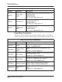
Optional
NA
NA
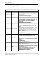
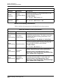
CE Interlocks
Tilted Spindle (0 to 15 degrees)
Autoloader Handling System
Optional
Optional
Optional
ProVectus (2")
NA
NA
Optional
Fortis (4")
Optional
NA
Optional
ProFortis (4")
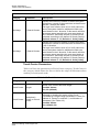
Note: Not all the configurations can be upgraded on the customer’s site.
P/N 97100-9002-000-14 Ver 06/05
1.6-3
Additional Models: Tilted Spindle, Autoloader, Large Area (for dicing 300 mm circular or 12"x9"rectangular
workpieces) on the Pro-type machines, according to the above configurations.
Vectus (2")
Models/ Features
Table 6-1: Available Models of the 7100 Dicing Series
ADT Model 7100 Semi-Automatic Dicing System Operations Manual
Available Models
Advanced Dicing Technologies Ltd.
1.6-4
ADT Model 7100 Semi-Automatic Dicing System Operations Manual
Available Models
ADT Model 7100 Semi-Automatic Dicing System Operations Manual
System Description
2
SYSTEM DESCRIPTION
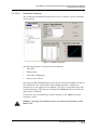
This chapter describes the Model 7100 Series elements. The first section
describes the main subsystems (Front Panel, Dicer and Vision System).
The second section describes the Graphic User Interface of the Model 7100
Series software.
3
1
2
4
5
12
11
10
6
9
7
8
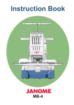
1 Monitor
2 Light Tower
3 Cut Cover
Interlock Key
4 Main Circuit
Breaker
5 Front Panel
6 Cut Cover
7 Mouse
8 Front Door
9 Keyboard
10Air and Water
Gun
11Load/Unload
Cover
12Load/Unload
Interlock Key
(7100EUR)
Figure 2-1: Model 7100 External Parts at a Glance
P/N 97100-9002-000-14
Ver 06/05
2-1
System Description
Advanced Dicing Technologies Ltd.
2-2
ADT Model 7100 Semi-Automatic Dicing System Operations Manual
Main Subsystems
2.1
Main Subsystems
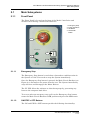
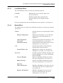
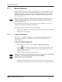
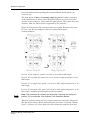
2.1.1
Front Panel
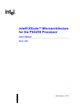
The Front Panel is located on the front of the Model 7100 Series and
includes the following controls and indicators:
1
2
3
4
Emergency Stop
Power Indicators
ON Button
STOP/OFF
Button
1
3
2
4
Figure 2-2: Model 7100 Series Front Panel
2.1.1.1
Emergency Stop
The Emergency Stop button is used when a hazardous condition exists in
the System or if the User needs to stop the System immediately.
Once the Emergency Stop button is pressed, the Main Circuit Breaker (see
Figure 2-1) disconnects the power from the saw. The System immediately
stops all Axes and disengages the Motor Drivers.
The PC UPS allows the software to shut down properly, preventing any
harm to the computer hard drive.
To recover after an emergency stop, pull out the Emergency Stop button,
rotate the Main Circuit Breaker to ON position and press the ON button.
2.1.1.2
ON/STOP > OFF Buttons
The ON and STOP > OFF buttons provide the following functionality:
P/N 97100-9002-000-14
Ver 06/05
2.1-1
Main Subsystems
The ON button powers on the Components and the PC, which then
starts loading the software. When the ON button is pressed, it
lights.
The STOP > OFF button stops the system operation (if pressed
once) and shuts down the System (if pressed twice). To start the
System up again, press ON and wait for the GUI screen asking for
the User Password.
This button enables the operator to immediately stop any activity in order
to prevent self-injury or damaging the material.
Note: The STOP/OFF button is spring-loaded to always be ready in its "out"
position.
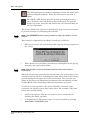
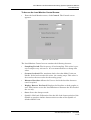
This feature is supported by the Model 7100 Series as follows:
•
When pressed once, the system stops and a pop-up message appears on
the screen:
•
When pressed a second time (equivalent to clicking Yes in the pop-up
message), the system shuts down.
Note: Wait at least one second between the first button press and the
confirmation.
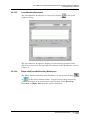
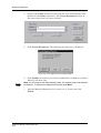
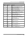
When the Stop button is pressed for the first time, the system stops at its
current location in all axes, excluding the Z-axis, which moves up (if stop is
pressed during the first init, the Z-axis also freezes). The user can also
define in the Setup and Diagnostics parameters that the Spindle and the
Cooling Block water should stop when the Stop button is pressed.
In order to resume operation, the system should be activated. Upon
activation, the regular system logic takes effect. For example, if the Stop
button was pressed during:
•
Any Teach sequence: The process stops. It can be resumed by reteaching the whole sequence.
•
A cutting process: The process stops. It can be resumed by pressing
Auto Run or Full Wafer Cut.
Advanced Dicing Technologies Ltd.
2.1-2
ADT Model 7100 Semi-Automatic Dicing System Operations Manual
Main Subsystems
In systems with Autoloader, the Stop button behaves the same way as in
a standard system. Upon Stop confirmation (the second press), the system
becomes idle, while the Autoloader performs initiation. All buttons are
disabled until the Autoloader initiation is completed.
Note: The user is prompted to manually remove all the workpieces that are not
properly positioned in the cassette but are situated elsewhere between the
Cassette Compartment and the Cutting Chuck. The workpieces are to be
removed before Stop confirmation.
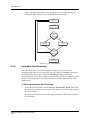
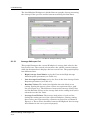
If the Stop button is pressed, while the system is in Auto Run mode, the
system finishes the current process and brings the workpiece to the
manual unload station. The user is prompted to manually unload the
workpiece. In order to return to the Auto Run mode, press Auto Run.
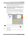
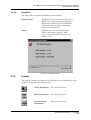
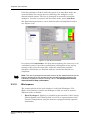
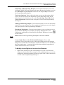
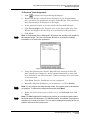
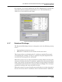
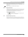
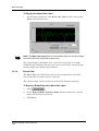
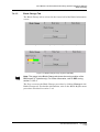
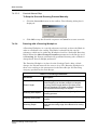
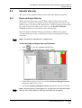
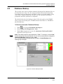
The Stop button parameters can be defined under Cutting Block station
(see Figure 2-3).
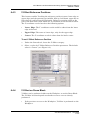
Figure 2-3: Stop Button Parameters
Note: Power Up the system only after the monitor LED indicator has gone off.
The system can be also stopped by clicking the stop icon
(see section 2.2.9).
2.1.1.3
on the screen
Power Lights
The two power lights indicate the power status in the Main Power Unit
(MPU), as follows:
P/N 97100-9002-000-14
Ver 06/05
2.1-3
Main Subsystems
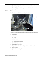
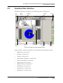
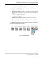
2.1.2
•
The AC Input light is lit to indicate presence of AC power in the
System.
•
The 24 VDC light is lit when power is available in all outlets of the
power supply.
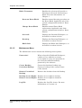
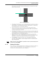
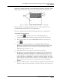
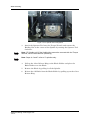
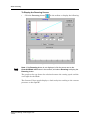
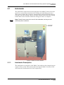
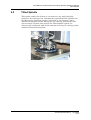
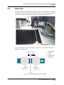
Dicer
The Dicer is where Workpieces are aligned and then cut.
1
2
3
4
5
3
Cutting Chuck
Vision System
Cooling Block
Spindle Unit
Height Device
2
4
1
5
Figure 2-4: Dicer
The Dicer includes the following main components and sub-components:
1
Cutting Axes
a.
X-Axis
b.
Y-Axis
c.
Z-Axis
d.
Theta Axis
e.
Rotational Axis (Spindle)
2
Spindle Unit (2" or 4")
3
Cooling Block (2"/3" or 5")
4
Height Device (Non-Contact Height Device or Mechanical Button)
5
Vision System
6
Quick-Change Cutting Chuck
Advanced Dicing Technologies Ltd.
2.1-4
ADT Model 7100 Semi-Automatic Dicing System Operations Manual
Main Subsystems
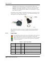
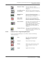
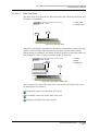
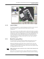
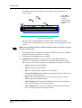
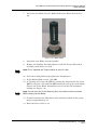
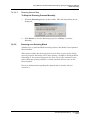
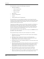
2.1.2.1
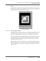
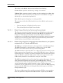
Vision System
The Model 7100 Series incorporates a high-performance Vision System
that executes precise positioning of Workpieces for Alignment and Kerf
Checking.
1 Camera
2 Microscope
3 Illumination Unit
1
2
3
Figure 2-5: Vision System
The Vision System includes the following Components:
2.1.2.1.1
•
Camera
•
Microscope
•
LED Illumination Unit (Oblique and Vertical)
Microscope and Camera
The Vision System of the Model 7100 Series includes a Camera with x30
(ProFortis and ProVectus only), x60, x120 (standard), or x240
magnification Microscope. Once the Model 7100 has been initialized, the
Vision System provides real-time images from the Camera, displayed in
the Field of View (FOV) of the Video Workspace. The images are supplied
by a monochrome video acquisition board contained in the Model 7100
Series PC.
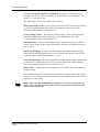
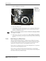
2.1.2.1.2
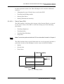
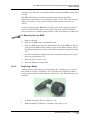
Illumination
The Microscope features two standard types of LED illumination:
P/N 97100-9002-000-14
Ver 06/05
2.1-5
Main Subsystems
•
Coaxial: Vertical illumination passing through the Microscope,
generally used on silicon Workpieces, which have reflective surfaces.
•
Oblique: Surrounding illumination on the sides of the Microscope,
generally used on Ball Grid Array (BGA) or metal Workpieces, which
have diffusive surfaces.
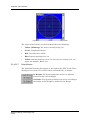
Illumination of the Workpiece intensifies the display of each pixel viewed
using a range of 0-255, where 0 produces a very dark (black) display, and
255 produces a very light (white) display.
2
1 Oblique
2 Coaxial
1
Figure 2-6: Illumination Accessories Attached to the Microscope
The 7100 Series machines can also be equipped with optional Halogen
illumination accessories for Coaxial or Oblique illumination (see also
Table 6-1).
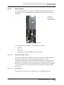
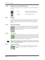
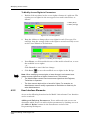
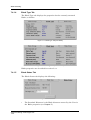
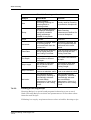
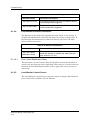
2.1.3
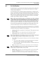
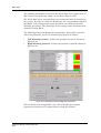
Light Tower
The Light Tower indicates the status of the Model 7100. In general,
a green light indicates normal system operation, yellow light
indicates that there is a need of a user interference, while a red light
indicates that an error has occurred. The Light Tower indications
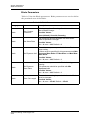
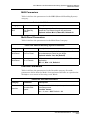
are given in Table 2-1.
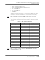
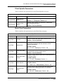
Table 2-1: Light Tower States
Red
Yellow
Green
System State
Med Flash
Off
Off
Error.
Off
Off
Off
The system is not initiated.
Off
On
Off
The system is idle
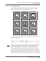
Off
Med Flash
Off
Process paused, operator call.
Off
Off
On
The system is running in Auto mode
Off
Off
On
Manual Operation
Advanced Dicing Technologies Ltd.
2.1-6
ADT Model 7100 Semi-Automatic Dicing System Operations Manual
Main Subsystems
Table 2-1: Light Tower States
Red
Yellow
Green
System State
Off
Off
On
The last workpiece is being processed
(relevant for systems with Autoloader)
Off
Rapid Flash Off
User interference required (operator call)
Off
Med Flash
Wizard is displayed, operator action is
required.
Off
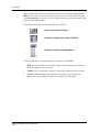
Note: The Light Tower indicators may vary since they can be configured to
meet individual customer requirements.
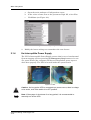
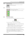
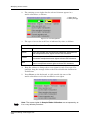
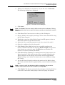
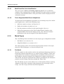
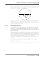
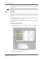
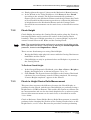
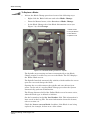
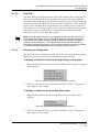
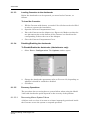
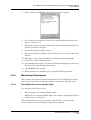
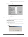
2.1.3.1
Stand-alone Buzzer on Light Tower
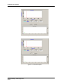
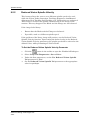
The standard light tower has a buzzer installed above the red light (see
Figure 2-7). This buzzer is wired to the red light and is activated whenever
the red light illuminates. Software Version 5.6 or later support a standalone buzzer configuration. This means that the buzzer is wired separately
and operates independently of the lights.
Figure 2-7: Buzzer in Light Tower
When this feature is enabled, the buzzer goes off only when the following
events take place:
•
Dress Block Change
•
Alignment Failure
•
Blade Change
•
Cutting Cycle Completed
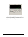
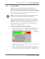
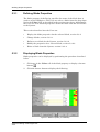
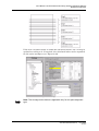
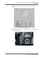
To Enable the Stand Alone Buzzer:
1
Configure the I/O PCB:
P/N 97100-9002-000-14
Ver 06/05
2.1-7
Main Subsystems
a.
Open the main workspace Configuration screen.
b.
In the value column, next to the parameter Digit I/O, select: Yes.
c.
Click Save (see Figure 2-8).
Figure 2-8: Enabling the Digital I/O PCB
2
2.1.4
Modify the buzzer wiring to accommodate the new feature.
Un-Interruptible Power Supply
The PC Un-Interruptible Power Supply assures that in case of an abnormal
System stopping (such as pressing the Emergency Stop button or in case
of a power failure) the computer still has an independent power input to
shut down properly. The UPS is located inside the system bench.
Figure 2-9: UPS
Caution: As long as the UPS is connected to a power source, there is voltage
on its outlet, even if the switch is in OFF position.
Note: If the system is shut down for a long period, it is recommended to
manually turn off the UPS.
Advanced Dicing Technologies Ltd.
2.1-8
ADT Model 7100 Semi-Automatic Dicing System Operations Manual
Graphical User Interface
2.2
Graphical User Interface
When the software is launched, the following screen is displayed:
Run
Button
Blade
Indicator
Stop
Button
Toolbar
Menu Bar
Activity
Log
Workspace
Active User
Field
Gauges
Dicer Status
Indicator
Figure 2-10: Model 7100 Series Opening Screen
Each element of the main window is described in the following sections:
•
Menu Bar, section 2.2.1
•
Toolbar, section 2.2.2
•
Gauges, section 2.2.3
•
Dicer Status Indicator, section 2.2.4
•
Active User Field, section 2.2.5
•
Activity Log, section 2.2.6
•
Blade Indicator, section 2.2.7
•
Run Button, section 2.2.8
•
Stop Button, section 2.2.9
•
Workspaces, section 2.2.10
P/N 97100-9002-000-14
Ver 06/05
2.2-1
Graphical User Interface
2.2.1
Menu Bar
The menu bar in the main window contains seven menus, described on the
following pages.
2.2.1.1
User Menu
The User menu contains the following options:
2.2.1.2
System Init
Initializes the System.
Logout & Login
Allows to log out the current user and
log in a different one.
Registration
Defines new Users, their access level
and password.
Configuration
Defines different system configuration
options
Calculator
Provides access to an online calculator.
Language
Enables the User to change the
interface language. For more
information, see section 8.2.
Communication
Status
Displays the status of communication
between the PC and DSPs within the
System.
Exit to Windows
Exits the Model 7100 Series software
and returns to Windows.
Auto Menu
The Auto menu contains the following options:
Run
Starts the System running in Auto
mode.
Define Job
Enables Recipes to be assigned to a
Workpiece or group of Workpieces.
Auto Stop
Stops the operation of the System in
Auto mode.
Advanced Dicing Technologies Ltd.
2.2-2
ADT Model 7100 Semi-Automatic Dicing System Operations Manual
Graphical User Interface
2.2.1.3
Load Monitor Menu
The Load Monitor menu contains the following options:
Control
Enables the user to specify upper and
lower load limits.
Load
Displays graphs that represent the
measured load on the Spindle during
dicing.
For more information about Load Monitor menu options, see Chapter 8.
2.2.1.4
Manual Menu
The Manual menu contains the following options for carrying out manual
operations:
Vision
Includes options for operating the Vision
System.
Manual Alignment
Enables the Workpiece to be manually
aligned. For more information, see
Chapter 6.
Auto Alignment
(execute)
Automatically aligns the Workpiece. For
more information, see section 6.1.2.
Auto Kerf Check
Automatically checks the kerf. For more
information, see section 6.3.4.
Cut
Includes an option for initiating the
Partial Wafer Cut procedure.
Partial Wafer Cut
Services
Enables the cutting of a partially cut
Workpiece to resume, see section 6.5.1
Includes options for Blade changing and
placing Workpieces, and for performing
Process Height.
Process Height
Executes the Blade Height procedure.
For more information, see section 7.3.
Blade Change
Initiates the Blade Change procedure.
For more information, see section 7.4.
Execute
Place Workpiece
Enables a Workpiece to be placed on the
Cutting Chuck. For more information,
see section 3.5.
Remove Workpiece
Enables a Workpiece to be removed
from the Cutting Chuck. For more
information, see section 3.5.
P/N 97100-9002-000-14
Ver 06/05
2.2-3
Graphical User Interface
Blade Treatment
2.2.1.5
Enables the selection of Override or
Dressing as the mode for Dressing a
Blade. For more information, see
Chapter 7.
Dress on Dress Block
Enables manual dressing procedure on
the Dress Block. Applicable only if the
system configuration includes a Dress
Station.
Change Dress Block
Enables manual Dress Block
replacement. Applicable only if the
system configuration includes a Dress
Station.
Override
Displays the Override Workspace, as
described in section 2.2.10.6.
Dressing
Displays the Dressing Workspace, as
described in section 2.2.10.6.
Blade Info
Displays the Blade Info Workspace, as
described in section 2.2.10.6.
Maintenance Menu
The Maintenance menu contains the following menu options:
Protection!
When selected in Workbook Workspace,
enables a User with the necessary
access rights to carry out operations in
the selected workbook normally
protected by the software.
Create Backup
Creates the database backup copy
Periodical Backup
Creates a backup of the current status
of the System.
Restore Periodical
Backup
Restores the database from the Backup.
Backup Access Rights Displays access rights to backup.
Restore Access Rights Displays access rights to database
restoration.
Log File
Advanced Dicing Technologies Ltd.
2.2-4
Displays the Log File viewer. For more
information, see section 3.8.
ADT Model 7100 Semi-Automatic Dicing System Operations Manual
Graphical User Interface
2.2.1.6
Help Menu
The Help menu contains the following menu options:
Books Online
Enables the User to open the soft copy of
Model 7100 Series Operations Manual,
Maintenance Manual, Pre-Installation
Guide and the manuals for additional
options (see Chapter 9).
About
Displays the version number of the
Model 7100 Series software, DCE
version and the Vision Card type (see
Figure 2-11).
Figure 2-11: Help/About Screen
2.2.2
Toolbar
The toolbar changes according to the Workspace. In all Workspaces, the
toolbar contains the following buttons:
Video Workspace
See section 2.2.10.2.
Main Workspace
See section 2.2.10.1.
Programming
Workspace
See section 2.2.10.3.
P/N 97100-9002-000-14
Ver 06/05
2.2-5
Graphical User Interface
Load Monitor
Workspace
See section 2.2.10.5.
Multiview
1, 4 or 12
Displays the current Kerf Check.
Displays the last four models found.
Displays up to 12 Kerf Checks.
2.2.2.1
Workbook
Workspace
See section 2.2.10.4.
Blade Info/
Override/
Dressing
Workspace
See section 2.2.10.6
Help
Loads the Operation Manual file.
Additional Tools - Main & Video Workspace
In the Main Workspace and Video Workspace, the toolbar contains the
following additional buttons:
Load/Unload
Wafer
Enables a Workpiece to be placed on
and removed from the Cutting
Chuck. For more information, see
Chapter 3.
Wafer AutoAlignment
Performs Auto Alignment on the
selected Workpiece. For more
information, see Chapter 6.
Wafer Manual
Alignment
Starts the Manual Alignment
process. For more information, see
Chapter 6.
Advanced Dicing Technologies Ltd.
2.2-6
ADT Model 7100 Semi-Automatic Dicing System Operations Manual
Graphical User Interface
2.2.2.2
Manual Y Offset
Starts the Manual Y Offset
procedure. For more information, see
Chapter 6.
Auto/Manual Cut
Verification
Starts the Cut Verification process.
For more information, see Chapter 6.
Manual Kerf
Check
Starts the Manual Kerf Check
process. For more information about
Kerf Checking, see Chapter 6.
Wafer Full/
Partial Cut
Gives the user two options: Full
Wafer Cut and Partial Wafer Cut.
For more information, see Chapter 6.
Dress Station
Gives the user two options: Dress on
Dress Block and Change Dress
Block. Applicable only if the system
configuration includes a Dress
Station.For more information, see
Chapter 9
Unlock LU Cover
Disengages the Load/Unload Cover
Interlock. (Available on EUR and LA
configured systems).
Additional Tools - Programming Workspace
In the Programming Workspace, the toolbar contains the following
additional buttons:
Save
Saves the current parameters
defined in the Programming
Workspace.
Cancel
Cancels the last changes.
Delete
Deletes any selected recipe except
for the templates or the active
recipe.
Apply
Applies the last change.
P/N 97100-9002-000-14
Ver 06/05
2.2-7
Graphical User Interface
2.2.2.3
Additional Tools - Workbook Workspace
In the Workbook Workspace, the toolbar contains the following additional
buttons:
2.2.3
Save
Saves the current parameters
defined in Workbook Workspace.
Cancel
Cancels the last changes.
Gauges
The Gauges on the right side of the main window indicate the speed of the
Spindle, current load on the Spindle, Blade Cooling Water and Spray
indication, Main Air Inlet Pressure and Vacuum level on the Workpiece
Holder.
2.2.3.1
Spindle Speed Gauge
The speed of the Spindle (in KRPM) is indicated by the needle
on the gauge. The Spindle can be activated or deactivated by
right-clicking the Spindle gauge and selecting Operate from
the menu that appears.
2.2.3.2
Load Gauge
The Load Gauge indicates the electrical current of the Spindle
Motor during dicing, and represents the dicing behavior. Load
Monitor indicates if the motor is overloaded with torque due to
dicing failure or bad dicing parameters. For more information
about Load Monitoring, refer to Chapter 8.
Note: On the Fortis machines (AC Spindle), the Load Gauge is not presented,
because with the AC type of spindle, the load changes as a function of velocity
and does not represent the load.
2.2.3.3
Air Pressure Gauge
Air Pressure Gauge indicates the Main Inlet Air Pressure
supplied to X-axis, spindle and other subsystems of the
machine.
Advanced Dicing Technologies Ltd.
2.2-8
ADT Model 7100 Semi-Automatic Dicing System Operations Manual
Graphical User Interface
2.2.3.4
Wafer Holder Gauge
Wafer Holder Gauge indicates the status of the wafer
(substrate) Vacuum level.
2.2.3.5
Water Adjust
The Water Adjust Gauge indicates the flow rate and spray of
the cutting water and cleaning jets.
Pressing the Water Adj. button activates the water flow.
2.2.4
Dicer Status Indicator
The lower right section of the main window displays the status of the Dicer.
Figure 2-12: Dicer Status Indicator
The status of the Dicer is indicated by the following LEDs:
•
Red: An error/failure exists. The System stops working and an error
message appears on the screen.
•
Yellow: User assistance required. A message appears on the screen.
•
Green: When blinking, the station is carrying out an operation.
Otherwise, green indicates that the station is in idle mode.
For example, when placing a Workpiece on the Cutting Chuck, at the point
when the User should load the Workpiece, the yellow light goes on.
The User can also initialize the Dicer by right-clicking the Dicer Status
Indicator and selecting (Dicer) Init from the popup menu displayed. For
further information about initialization, refer to Chapter 10.
Double-clicking on the Dicer Status Indicator displays the last error
message.
P/N 97100-9002-000-14
Ver 06/05
2.2-9
Graphical User Interface
2.2.5
Active User Field
The Active User field displays the current recipe file name assigned to the
loaded workpiece, and the operations performed, according to the recipe.
2.2.6
Activity Log
The Activity Log is located in the lower left corner. It provides a history log
of activities performed by the system.
Figure 2-13: Activity Log
Events that have scrolled off the display can be reviewed using the scroll
buttons.
2.2.7
Blade Indicator
The Blade Indicator on the left side of the main window displays
the Blade exposure. The bar, which represents the Blade in the
system, provides a guide as to the condition of the Blade based on
the Blade parameters specified in the Blade properties and the
current Recipe. The black pointer moves slowly up the guide as
the Blade wears down.
The colors in the Blade Indicator bar indicate the following:
•
Green: Blade exposure satisfactory, cutting can continue
•
Yellow: Blade exposure critical, cutting can only continue for a short
time
•
Red: Blade requires changing, no cutting possible
For more information about Blades and Blade changing, see Chapter 7.
Advanced Dicing Technologies Ltd.
2.2-10
ADT Model 7100 Semi-Automatic Dicing System Operations Manual
Graphical User Interface
2.2.8
Run Button
The Run Button serves both as a control and an indicator while the system
is in Auto Mode.
2.2.9
Ready
The system is idle. Press the button
to run the process.
In Progress
System is active. A process in
progress.
Paused
Process paused. The machine stops
at the end of the current kerf.
Stop Button
The Stop Button
stops any activity in order to prevent self-injury or
damaging the material.
The soft Stop button functions similarly to the Stop-Off button on
the Model 7100 Series Front Panel (see section 2.1.1.2). Clicking the Stop
Button stops the system and a pop-up message appears on the screen:
At this point, after clicking OK, the User can either press the OFF button
to power down the System, or continue the interrupted process from the
point, at which the soft Stop button was clicked.
Note: Wait at least one second between the first button press and the
confirmation.
Upon clicking the Stop Button, the system stops at its current location in
all axes, excluding the Z-axis, which moves up (if Stop is clicked during the
first init, the Z-axis also freezes) and the spindle, which turns off only if so
defined in the recipe. Stopping the cooling block water can also be defined
in the recipe.
P/N 97100-9002-000-14
Ver 06/05
2.2-11
Graphical User Interface
If the Stop button is clicked, while the system is in Auto Run mode, the
system finishes the current process and brings the workpiece to the
manual unload station. The user is prompted to manually unload the
workpiece. In order to return to the Auto Run mode, press Auto Run.
The Stop button parameters can be defined under Cutting Block station
(see Figure 2-14).
Figure 2-14: Stop Button Parameters
In systems with Autoloader, the Stop button behaves the same way as in
a standard system. Upon Stop confirmation (clicking Yes in the pop-up
message), the system becomes idle, while the Autoloader performs
initiation. All buttons are disabled until the Autoloader initiation is
completed.
Note: The user is prompted to manually remove all the workpieces that are not
properly positioned in the cassette but are situated elsewhere between the
Cassette Compartment and the Cutting Chuck. The workpieces are to be
removed before Stop confirmation.
2.2.10
Workspaces
The central portion of the main window is called the Workspace. The
Model 7100 software contains six Workspaces that are used to perform
different tasks, as follows:
•
Main Workspace: Displays a graphical representation of the Cutting
Chuck, Spindle and Vision System, as well as a representation of the
Cassette Compartment (only for Systems equipped with the optional
Autoloader).
Advanced Dicing Technologies Ltd.
2.2-12
ADT Model 7100 Semi-Automatic Dicing System Operations Manual
Graphical User Interface
•
Video Workspace: Displays a real-time video image of the Workpiece
on the Cutting Chuck. The Video Workspace also displays the Cut Map
and the Wizards that guide the User through selected procedures.
•
Programming Workspace: Enables the User to create and edit
Recipes assigned to Workpieces.
•
Workbook Workspace: Displays a set of operations and parameters
used to prepare the System for operation. There are two Workbooks, as
follows:
•
Setup & Diagnostics Workbook
•
Calibration Workbook
•
Load Monitor Workspace: Displays load monitoring statistics.
•
Blade Info/Override/Dressing Workspace: Displays the Blade
parameters and the set of operations and parameters used for Blade
Dressing.
The Workspace displayed in the main window is selected by clicking one of
the following buttons from the toolbar:
Main
Video
Programming
Workbook
Load
Monitoring
Override/
Dressing
Blade Info
MultiLanguage
Support
Figure 2-15: Workspace Buttons
P/N 97100-9002-000-14
Ver 06/05
2.2-13
Graphical User Interface
2.2.10.1
Main Workspace
The Main Workspace is automatically displayed when the software is
launched and can be redisplayed at any time by clicking the Main
Workspace toolbar button. When selected, the Main Workspace displays
the following:
Figure 2-16: Main Workspace
The Main Workspace displays an animated graphical representation of the
Workpiece being processed in real-time.
Advanced Dicing Technologies Ltd.
2.2-14
ADT Model 7100 Semi-Automatic Dicing System Operations Manual
Graphical User Interface
2.2.10.1.1
Top View Area
The Top View area depicts the System stations from above, including the
Workpiece (if present), Spindle, Blade and Camera. When cutting is
performed, the Blade is shown moving across the surface of the Workpiece.
1 Y-Axis
2 Spindle with
Blade
3 Camera
4 X Bellows
5 Cutting Chuck
1
2
3
5
4
Figure 2-17: Top View Area
The presence of a Workpiece within the System is indicated by a blue disk
on the Chuck.
Right-clicking anywhere in the Top View area displays the following popup
menu:
Figure 2-18: Top View Popup Menu
The options in the popup menu enable the Top View to be manipulated, as
follows:
•
Wafer zoom: Displays a close-up view of the Top View area.
•
Full View: Displays the Top View area in full, along with an insert
displaying the side view of the Theta Table.
P/N 97100-9002-000-14
Ver 06/05
2.2-15
Graphical User Interface
•
Show Z view: Toggles the display of the Side View area (see section
2.2.10.1.2).
•
Show Cameras: Toggles the display of the Camera, Microscope, and
Spindle with Blade in the Top View area.
•
Auto Switch Views: The System automatically switches between
Main Workspace and Video Workspace when necessary, for example,
after Manual Alignment is completed in Video Workspace and the
User clicks Finish, the Main Workspace is automatically displayed.
•
Load Monitoring: Specifies whether the current on the load monitor
is reflected in the color of the cuts displayed in the cut map.
•
Load Monitor Graph: Displays a real-time Load Monitor graph at
the bottom of the Top View area showing the current of the Spindle.
1
1 Upper Limit
2 Lower Limit
2
Figure 2-19: Load Monitor Graph
If the current is above the Upper Limit or below the Lower Limit, the
Spindle stops.
The User can click in the Load Monitor graph to zoom in and click
to display the Load Monitor graph in full again. The graph can be
resized by clicking and dragging its borders.
Additionally, the buttons at the top of the Top View area enable the Top
View area to be manipulated as follows:
Gradually zooms in on the Top View area.
Gradually zooms out of the Top View area.
Displays the Top View area in full.
Displays a close-up view of the Cut Map.
Advanced Dicing Technologies Ltd.
2.2-16
ADT Model 7100 Semi-Automatic Dicing System Operations Manual
Graphical User Interface
2.2.10.1.2
Side View Area
The Side View area depicts the Dicer from the side, showing the Dicer and
Workpiece (if present).
1 Theta Table
2 Cutting Chuck
2
1
Figure 2-20: Side View Area
When Process Height is performed, the Blade is shown being lowered to the
surface of the Cutting Chuck before returning to its previous position.
When dicing is performed, the Blade is shown moving across the surface of
the Workpiece, one cut index at a time, in the Y direction.
1 Spindle
2 Blade
3 Workpiece
2
1
3
Figure 2-21: Dicing from the Side View
The buttons at the top of the Side View area enable the Side View area to
be manipulated as follows:
Gradually zooms in on the Side View area.
Gradually zooms out of the Side View area.
Displays the Side View area in full.
P/N 97100-9002-000-14
Ver 06/05
2.2-17
Graphical User Interface
2.2.10.2
Video Workspace
The Video Workspace is selected by clicking
toolbar.
Main Workspace Window (Reduced)
Wizard/Model
in the main window
Field of View
Illumination Controls
Axes Controls
Figure 2-22: Video Workspace
The Video Workspace displays a real-time video image of the Cutting
Chuck from the camera mounted on the Spindle. The area of the Video
Workspace where the video image is displayed is called the Field of View
(FOV). The portion of the Workpiece in focus in the FOV can be precisely
positioned using the Display Controls.
Right-clicking in the Video Workspace enables the User to refresh the
image, save it or load an image stored on the computer.
Illumination of the Workpiece is set with the Illumination Controls. These
controls define the type of light used to illuminate the part of the
Workpiece in focus and its intensity.
The Video Workspace contains tools for setting magnification levels (Zoom)
used to display, align and cut objects, according to specific needs.
Note: The Zoom option is available only on machines that support a “Teli”
camera type.
Advanced Dicing Technologies Ltd.
2.2-18
ADT Model 7100 Semi-Automatic Dicing System Operations Manual
Graphical User Interface
In other operation modes, the Video Workspace also contains additional
tools for:
2.2.10.2.1
•
Changing the type of Search Area used in the FOV
•
Teaching and finding models
•
Setting Auto Focus
•
Setting illumination intensity
Field of View (FOV)
The FOV displays real-time video images of the Cutting Chuck, as viewed
by the active camera. The FOV is used when doing any of the following
procedures:
•
Teaching Alignment
•
Teaching Index
•
Teaching Kerf Checking
•
Inspection
Note: Procedures performed with the FOV are described in detail in Chapter 6.
The FOV includes three visual Guides that are used to precisely position a
particular location of the Workpiece in the center of the FOV display:
•
Reticle
•
Search Area
•
Teach Area
Search Area (green)
Teach Area
(blue)
Reticle (green)
Figure 2-23: FOV Display Guides
P/N 97100-9002-000-14
Ver 06/05
2.2-19
Graphical User Interface
Reticle
The Reticle consists of green crosshairs that are used to pinpoint a location
on the part of the Workpiece displayed in the FOV. In addition, the
horizontal line of the Reticle is used when teaching Alignment or
performing Manual Alignment. The length of the lines of the Reticle can be
adjusted by using the Guide Control (the central Display Control.)
Teach Area
The Teach Area is a blue box that is used when Teaching Alignment or
Kerf Checking. The Teach Area defines the area to be taught to the system
when performing these procedures. The size of the Teach Area can be
adjusted by using the Guide Control (the central Display Control) or by
clicking and dragging its borders with the mouse.
Search Area
The Search Area is used to define the field the Vision System will use to
search for anything taught in the Teach Area box.
In addition, the Search Area is a guide that can be used to focus on a
particular area of a Workpiece when performing certain operations. For
example, when performing Alignment, the Search Area helps the User to
focus on a particular street. The Search Area has a green outline, and its
shape is selected from the following options in the drop-down list to the
right of the FOV:
•
Box: A box centered in the FOV.
•
Parallel: Two horizontal parallel lines centered in the FOV.
•
Dashed: Two dashed horizontal parallel lines centered in the FOV.
The size of the Search Area can be adjusted using the Guide Control (the
central Display Control) or by clicking and dragging with the mouse.
2.2.10.2.2
Display Controls
The Video Workspace contains three Display Controls beneath the FOV
that are used to move the X, Y, Z and Theta axes and to precisely position
the image of the Workpiece displayed by the active camera.
X/Y-Axis Controls
The X/Y-Axis Controls (left Display Control) move the image displayed in
the FOV along the X and Y Axes of the Workpiece.
The left and right arrows move the Cutting Chuck along the X-Axis. The
exact position is displayed in the X field. The up and down arrows move the
camera along the Y-Axis. The exact position is displayed in the Y field.
Advanced Dicing Technologies Ltd.
2.2-20
ADT Model 7100 Semi-Automatic Dicing System Operations Manual
Graphical User Interface
Clicking on an axis button turns the coordinate value on the current axis
into a reference point (zero) as shown in Figure 2-24.
Figure 2-24: Zeroed Axis Buttons
The Axis buttons turn blue and an "r" (reference) letter appears next to the
Axis letter.
Clicking the central box changes the type of movement, as follows:
F: Moves at the Fast Velocity, as defined in the X and Y Axes
parameters in the Setup & Diagnostics workbook.
S: Moves at the Slow Velocity, as defined in the X and Y Axes
parameters in the Setup & Diagnostics workbook.
P: Moves one pixel at a time.
I: Moves Index by Index along the Y-Axis, using the Index value
specified in the Recipe (relevant only if a Cut Map exists).
Note: The Workpiece and the Vision head can be moved along the X and Y
Axes by double-clicking a location inside the FOV.
Guide Controls
The Guide Control (central Display Control) is used to change the size of
the Guides (Reticle, Teach Area and Search Area) displayed in the FOV.
Clicking the central box toggles the item to be resized, as follows:
S: Search Area
R: Reticle
T: Teach Area
The left and right buttons adjust the width of the selected Guide, while the
up and down buttons adjust the height of the selected Guide.
Note: When the Search Area is Parallel or Dashed, the left and right buttons
are disabled. Only the height can be changed when using these Search Areas.
P/N 97100-9002-000-14
Ver 06/05
2.2-21
Graphical User Interface
Click here to move 1 pixel up
Y Axis
X Axis
Click here to move 1 pixel down
Click here to move 1 pixel to the right
Click here to move 1 pixel to the left
Double-clicking any point in the FOV bring the FOV center to that point.
Center-clicking moves the FOV center 1 pixel along the axes, depending on
the zone clicked:
Note: The axes can also be moved by typing in coordinates values and
pressing Enter.
Z/T Axis Controls
The Z/T Axis Controls (right Display Control) move the image displayed in
the FOV along the Z and Theta Axes.
The left and right arrows rotate the Cutting Chuck along the Theta Axis.
The exact position on the Theta Axis is displayed in the T field. The up and
down arrows move the camera along the Z-Axis (change the focus of the
camera on the Workpiece). The exact position on the Z-Axis is displayed in
the Z field.
Clicking the central box changes the type of movement, as follows:
F: Moves at the Fast Velocity, as defined in the Z and T Axis
parameters in the Setup & Diagnostics workbook.
S: Moves at the Slow Velocity, as defined in the Z and T Axis
parameters in the Setup & Diagnostics workbook.
P: Moves one pixel at a time.
A: Toggles between the angles defined in the Recipe.
Note: For more information about the Setup & Diagnostics workbook, refer to
the ADT Model 7100 Semi-Automatic Dicing System Maintenance Manual.
Advanced Dicing Technologies Ltd.
2.2-22
ADT Model 7100 Semi-Automatic Dicing System Operations Manual
Graphical User Interface
2.2.10.2.3
Zoom Controls
Note: The Zoom option is available only on machines that support a “Teli”
camera type.
Digital Magnification enables using digital zoom to improve system
performance regarding alignment and accuracy. The Video Workspace
contains the tools for setting magnification levels used to display, align and
cut objects, according to specific needs. The feature supports a continuous
digital magnification range between X0.5 and X2.0.
Note: This option is available only on machines supporting Scorpion cameras.
The user can set magnifications for a variety of applications, including:
•
Inspection
•
Y-Offset
•
Teaching models
•
Alignment Procedure
•
Teaching Kerf Checking
To Enable the Zoom Option:
1
Open the main workspace Configuration screen by selecting
Configuration from the User menu.
2
In the value column, next to the parameter Zoom, select: Yes.
The camera type automatically changes to Teli (see Figure 2-25).
3
Click Save.
Figure 2-25: Zoom Option Configured
P/N 97100-9002-000-14
Ver 06/05
2.2-23
Graphical User Interface
After configuring the Zoom option, magnification can be set in the Video
Workspace by using the following controls (see Figure 2-26):
•
Manually adjusting the Magnification/Zoom ComboBox control to x1,
x2 or x4
•
Clicking the +/- button in the video screen of the Video Workspace GUI
Figure 2-26: Zoom Controls
Note: During the Teach Align Mode Pre-Condition state, the user must choose
the Magnification size. It is also possible to teach Magnification for each model
individually.
To Enable Digital Magnification:
1
Open the main workspace Configuration screen.
2
In the value column, next to the parameter Zoom, select: Yes.
The camera type automatically changes to Scorpion.
3
Click Save (see Figure 3).
Figure 3: Enabling Digital Magnification
To Use Digital Magnification:
In the Video Workspace, magnification can be set according to the
following:
Note: The magnification increment unit is X0.1.
•
Manually entering a Magnification value between X0.5 and X2.0.
Advanced Dicing Technologies Ltd.
2.2-24
ADT Model 7100 Semi-Automatic Dicing System Operations Manual
Graphical User Interface
•
Clicking the “ticker” up and down arrows next to the magnification
value in the Video Workspace GUI.
Figure 4: Using Digital Magnification
2.2.10.2.4
Illumination Controls
The two Illumination Controls to the right of the FOV are used to adjust
the following display values:
The intensity of the Vertical (Coaxial) illumination used
on the part of the Workpiece displayed in the FOV.
The intensity of the Oblique (Ring) illumination used on
the part of the Workpiece displayed in the FOV.
Each setting is defined by entering a value in the box to the right of each
control or by using the arrows. Illumination of the Workpiece intensifies
the display of each pixel viewed using a range of 0-255, where 0 produces a
very dark (black) display, and 255 produces a very light (white) display.
In addition, the vertical (coaxial) or oblique (ring) illumination can be
turned on and off (set to zero) by clicking the small box next to the
arrows. The box is green when the Illumination Control is activated
and gray when it is deactivated.
2.2.10.2.5
Wizard/Model Area
The Wizard/Model area at the lower left of the Video Workspace helps
guide the User through the steps needed to carry out a procedure, such as
Manual Alignment or Removing a Workpiece, and displays a close-up of
the Models being taught or searched for.
P/N 97100-9002-000-14
Ver 06/05
2.2-25
Graphical User Interface
Wizard
The Wizard tab displays step-by-step instructions for carrying out a
selected procedure.
Figure 2-1: Wizard Tab
In the example given in Figure 2-1, the User would place the workpiece on
the Cutting Chuck, and then click Finish.
The buttons located beneath the Wizard are used to do the following:
Aborts the current procedure.
Reverts to the previous step in a procedure.
Proceeds to the next step in a procedure.
Instructs the System to complete the procedure.
When a step in a procedure includes a physical action that the User has to
perform, the Wizard displays the appropriate instruction. For example,
when placing or removing a Workpiece from the Cutting Chuck, the
Wizard indicates when the User should perform the action before returning
to the software to click Finish.
Advanced Dicing Technologies Ltd.
2.2-26
ADT Model 7100 Semi-Automatic Dicing System Operations Manual
Graphical User Interface
Model
After the Teach procedure has been performed, the Model tab displays the
Model that was taught. During Alignment or Kerf Checking, the Model tab
displays the Model currently being searched.
Figure 2-2: Model Tab
2.2.10.2.6
Main Workspace Window
The Main Workspace Window provides a small representation of the Main
Workspace, as described in section 2.2.10.1. It depicts the Dicer from
above, including the Workpiece (if present), the Spindle and the Blade.
The User can manipulate the Main Workspace Window the same way as in
the Main Workspace. For example, right-clicking anywhere in the Main
Workspace Window displays the popup menu shown in Figure 2-18 and
described in section 2.2.10.1.1.
When working in the Video Workspace, it is useful if the Main Workspace
Window displays a close-up of the Cutting Chuck showing the Cut Map of
the current Workpiece (if one has been defined), including the position of
all Index cuts.
P/N 97100-9002-000-14
Ver 06/05
2.2-27
Graphical User Interface
Figure 2-3: Main Workspace Window in Video Workspace
The colors of the Indexes on the Cut Map reflect the following:
2.2.10.2.7
•
Yellow (blinking): The Index currently being cut.
•
Green: Completed Indexes.
•
Red: Cuts that have failed.
•
Blue: Indexes waiting to be cut.
•
Yellow: Indexes that have been cut once but are waiting to be cut
again, for example, Bevel cuts.
Other Buttons
The additional buttons that appear to the right of the FOV in the Video
Workspace are used to focus the Camera automatically, as follows:
At Height: The System performs auto focus with the
Camera at the current height.
On Wafer: The System performs auto focus according to
the height of the Workpiece defined in the Recipe.
Advanced Dicing Technologies Ltd.
2.2-28
ADT Model 7100 Semi-Automatic Dicing System Operations Manual
Graphical User Interface
2.2.10.3
Programming Workspace
The Programming Workspace, selected by clicking
in the main
window toolbar, enables the User to create and edit Recipes assigned to
Workpieces.
Figure 2-4: Programming Workspace
Selecting a Recipe in the Programming tree on the left of the Programming
Workspace displays its properties on the right of the Workspace. For
example, in the above figure, the properties for the TMPL_GPC Recipe are
displayed. Properties are modified by double-clicking in the Value field
and entering a value or selecting a value from a drop-down list.
Recipes include parameters that are divided into categories, listed below
the Recipe in the Programming tree. Selecting a category displays the
P/N 97100-9002-000-14
Ver 06/05
2.2-29
Graphical User Interface
parameters for that category on the right of the Programming Workspace,
as follows:
Figure 2-5: Recipe Parameters
Parameters are modified by double-clicking in the Value field and entering
a value or selecting a value from a drop-down list.
The buttons (tools) in the lower pane of the Programming Workspace
enable the User to perform the following operations:
•
Add parameters to and delete parameters from a Recipe, for more
details see Chapter 5.
•
Import and export Recipes, for more details see Chapter 5.
•
Teach Alignment, for more details see Chapter 6.
•
Teach Kerf Checking, for more details see Chapter 6.
•
Teach other parameters, for example, the Index, for more details see
Chapter 6.
For a detailed description of the Programming Workspace, see Chapter 5.
For a detailed description of Recipe parameters, refer to Appendix 3.
2.2.10.4
Workbook Workspace
The Workbook Workspace is selected by clicking
toolbar.
Advanced Dicing Technologies Ltd.
2.2-30
in the main window
ADT Model 7100 Semi-Automatic Dicing System Operations Manual
Graphical User Interface
There are three workbooks, as follows:
•
Setup & Diagnostics workbook, see section 2.2.10.4.1.
•
Calibration workbook, see section 2.2.10.4.2.
The User can open workbooks by selecting them from the Select
Workbook drop-down list or using the Explorer-style tree on the left of the
Workbook Workspace.
2.2.10.4.1
Setup & Diagnostics Workbook
By default, the Setup & Diagnostics workbook is displayed after clicking
the Workbook Workspace button in the main window toolbar, as follows:
Figure 2-6: Setup & Diagnostics Workbook
The Setup & Diagnostics Workbook enables the User to perform setup and
diagnostics procedures on all System components and sub-components.
Selecting a station, or one of its elements, in the Setup & Diagnostics tree
on the left of the workbook displays its setup parameters on the upper right
of the workbook. The lower pane changes according to the selected axis.
For example, Figure 2-6 displays the setup parameters for the X Axis in
the upper right pane of the workbook, as well as diagnostic functions
relating to the X Axis in the lower right pane. Setup parameters are
modified by double-clicking in the Value field and entering a value or by
selecting a value from a drop-down list.
P/N 97100-9002-000-14
Ver 06/05
2.2-31
Graphical User Interface
Overflow Sensor
In the Setup & Diagnostics tree, under Saw, the Overflow sensor is
displayed. This sensor is intended to prevent the damage to the System due
to the drain pan overflow, which may be caused by clogged drain outlet
Figure 2-7: Overflow Sensor Indication
If the drain pan becomes overflown, the indicator (see Figure 2-7) changes
its color from gray to red, and an error message appears (see Figure 2-8).
Figure 2-8: Water Overflow Message
Once an overflow is indicated the di-water supply to the cooling block and
to the Non-Contact Height Device becomes disabled. During the time that
the overflow sensor is on, the operator cannot operate the water. For more
details about the Overflow sensor, refer to the 7100 Series Maintenance
Manual.
For a detailed description of the setup parameters and diagnostic tests for
each station, refer to the ADT Model 7100 Semi-Automatic Dicing System
Maintenance Manual.
Advanced Dicing Technologies Ltd.
2.2-32
ADT Model 7100 Semi-Automatic Dicing System Operations Manual
Graphical User Interface
2.2.10.4.2
Calibration Workbook
The Calibration Workbook enables the User to calibrate specific elements
in the System.
Figure 2-9: Calibration Workbook
The following elements of the System can be calibrated:
•
Pixel Size
•
Illumination
•
Axes (Error Mapping)
•
Sensors (see below)
Selecting the High Magnifying Camera for the Vision Head (Microscope) in
the Calibration tree on the left of the workbook displays calibration
parameters on the right of the workbook. The User can perform pixel size
and illumination calibration by clicking the Calibrate buttons on the top
right of the workbook.
Parameters can be modified by double-clicking in the Value field and
entering a value.
Caution: Changing the calibration values can affect the performance of the
Model 7100.
P/N 97100-9002-000-14
Ver 06/05
2.2-33
Graphical User Interface
Sensors
The following sensors are listed under Sensor Calibration (see
Figure 2-10):
•
Main Air Sensor
•
Wafer Holder Vacuum Sensor
•
Chuck Holder Vacuum Sensor
•
Theta Vacuum Sensor
•
Theta Air Sensor
Figure 2-10: Calibration Workbook: Sensor Calibration
This section is designed for use by version 4.5.2 or later.
Advanced Dicing Technologies Ltd.
2.2-34
ADT Model 7100 Semi-Automatic Dicing System Operations Manual
Graphical User Interface
2.2.10.5
Load Monitor Workspace
The Load Monitor Workspace is selected by clicking
window toolbar.
in the main
Figure 2-11: Load Monitor Workspace
The Load Monitor Workspace displays load monitoring statistics from
different perspectives. For a detailed description of this Workspace, refer to
Chapter 8.
2.2.10.6
Blade Info/Override/Dressing Workspace
The Blade Info/Override/Dressing Workspace is selected by clicking
or
in the main window toolbar. Toggle between these buttons by
clicking the arrow next to the button and selecting either Dressing,
Override, or Blade Info from the options displayed.
P/N 97100-9002-000-14
Ver 06/05
2.2-35
Graphical User Interface
Figure 2-12: Dressing Workspace
Figure 2-13: Override Workspace
Advanced Dicing Technologies Ltd.
2.2-36
ADT Model 7100 Semi-Automatic Dicing System Operations Manual
Graphical User Interface
Figure 2-14: Blade Info Screen
The Blade Info/Override/Dressing Workspace enables the User to start
and stop Blade Dressing and displays information about the Blade
Dressing procedure. Blade Dressing is performed to prepare a Blade for
use, either using a Dressing Workpiece or by Override cutting.
The Blade Info/Override/Dressing Workspace is described in section
7.4.3.
P/N 97100-9002-000-14
Ver 06/05
2.2-37
Graphical User Interface
Advanced Dicing Technologies Ltd.
2.2-38
ADT Model 7100 Semi-Automatic Dicing System Operations Manual
System Configuration
2.3
System Configuration
The Configuration Dialog box shown in Figure 2-15 enables the user to see
what components are installed on the system. The user can update the
system configuration if there are any changes (e.g. Height Device type
change). Once configured, the System is aware of which features it is
equipped with.
To Configure the System:
1
From the User Menu, select Configuration. The Configuration screen
appears.
Figure 2-15: Configuration Dialog Box
2
Configure the features according to the System by double-clicking the
Value cell of each feature and selecting Yes or No from the drop-down
list.
3
Click Save. A pop-up dialog box appears informing the user that after
saving the changes, the system will exit to Windows, and the user will
need to restart the GUI.
P/N 97100-9002-000-14
Ver 06/05
2.3-1
System Configuration
Advanced Dicing Technologies Ltd.
2.3-2
ADT Model 7100 Semi-Automatic Dicing System Operations Manual
Menu Navigation Chart
2.4
Menu Navigation Chart
P/N 97100-9002-000-14
Ver 06/05
2.4-1
Menu Navigation Chart
Advanced Dicing Technologies Ltd.
2.4-2
ADT Model 7100 Semi-Automatic Dicing System Operations Manual
System Operation
3
SYSTEM OPERATION
This chapter describes the Model 7100 operation in automatic and manual
workflows and includes the following sections:
•
Powering Up and Down, section 3.1
•
Logging in, section 3.2
•
System Initialization, section 3.3
•
Defining Jobs, section 3.4
•
Placing/Removing Workpieces, section 3.5
•
Model 7100 Workflows, section 3.6
•
Stopping System Operation, section 3.7
•
Log File, section 3.8
P/N 97100-9002-000-14
Ver 06/05
3-1
System Operation
Advanced Dicing Technologies Ltd.
3-2
ADT Model 7100 Semi-Automatic Dicing System Operations Manual
Powering Up/Down Procedures
3.1
Powering Up/Down Procedures
3.1.1
Powering Up the System
This section describes the procedure for powering up the Model 7100 at the
beginning of a session. Once powered on, the Model 7100 can be run
continuously. It only needs to be powered down in order to perform repair
and maintenance procedures. For additional information about powering
down the System, see section 3.1.2.
Note: Before powering up the system, make sure that both the computer and
the monitor are powered off (monitor LED is off).
To Power Up the System:
3.1.1.1
1
Turn on the main Circuit Breaker at the right side of the System, if it
has been turned off (normally it is left in the On position).
2
On the System Front Panel, press the ON
button. The PC inside
the System turns on and automatically launches the Model 7100
software.
Powering Up After an Abnormal Shut Down
In case the System has abnormally shut down, the user has to restore the
process database. Follow the on-screen instruction of the Database
P/N 97100-9002-000-14
Ver 06/05
3.1-1
Powering Up/Down Procedures
Restore dialog window that appears on the monitor screen after an
abnormal shut down:
Figure 3-1: Database Restore dialog window
Checking the "Allow Database Restoration" checkbox enables the options of
database restoration from backup.
Note: After Power On, and before normal operation, it is recommended to
warm up the system by running a simulated dicing session for thirty minutes.
The User should place a Workpiece on the Cutting Chuck, define and assign a
Recipe, and run simulated dicing for thirty minutes. The User must ensure that
the Cut Depth is set so that the Blade does not enter the Workpiece and no
Kerf Check or Cut Verification algorithm is selected. The spindle should rotate
at typical speed (the speed used for dicing) with cutting water on.
This simulated dicing, in the system steady state, warms up the Model 7100 to
prepare it for normal operation. Advanced Dicing Technologies Ltd. suggest
creating a warm-up recipe.
Advanced Dicing Technologies Ltd.
3.1-2
ADT Model 7100 Semi-Automatic Dicing System Operations Manual
Powering Up/Down Procedures
3.1.2
Powering Down the System
Powering down is required to perform maintenance on the Model 7100.
Powering down the System every night is not required.
Note: It is recommended to stop System operation before initiating the power
down procedure.
To Power Down the System:
1
Press the Stop>OFF
button. The system stops and a pop-up
message appears on the screen:
2
Press the Stop>OFF button a second time (equivalent to clicking Yes
in the pop-up message), the system shuts down. For more details about
the Stop>OFF button, refer to section 2.1.1.2,
Note: Wait at least one second between the first button press and the
confirmation.
Danger: Voltage remains in the inlet of the Main Power Unit (MPU) even after
completing the preceding Power Down procedure. Be sure to totally disconnect
the System from the electricity supply before performing maintenance or repair
procedures.
The system powers down in the following order:
1
The computer shuts down
2
The machine turns off
3
The monitor turns off in about 45 seconds after the machine.
The powering down process takes 1 to 1.5 minutes.
Note: Before powering the system up, make sure that both the computer and
the monitor are powered off (monitor LED is off).
3.1.2.1
Lockout/Tagout
To Lockout/Tagout the System:
1
Shut down the main circuit breaker on the right side of the machine.
2
In order to lock the machine in power-off state, lock the main circuit
breaker door.
P/N 97100-9002-000-14
Ver 06/05
3.1-3
Powering Up/Down Procedures
Advanced Dicing Technologies Ltd.
3.1-4
ADT Model 7100 Semi-Automatic Dicing System Operations Manual
Logging In
3.2
Logging In
When the Model 7100 software is launched, the login dialog box is the first
window displayed. The User Interface will not open unless a valid user
name and password are entered.
Figure 3-2: Login Dialog Box
To Log into the System:
1
Select a name from the User drop-down list.
2
Enter the password in the Password field. Asterisks are displayed in
place of each character.
Note: Click Reset to clear the User and Password fields, if required.
3
Check the Unit system checkbox in order to have the System run its
initialization routine immediately after displaying the 7100 Opening
Screen.
Note: If the Init system checkbox is not checked, the System can be initialized
manually by selecting System Init from the User menu. For further
information, see Chapter 4 of the ADT Model 7100 Semi-Automatic Dicing
System Maintenance Manual.
4
Click OK. The 7100 Graphic User Interface Opening Screen is
displayed, and the System automatically begins running its
initialization routine (unless the Init system checkbox has not been
selected).
Note: For information about adding new Users and User access levels, see
Chapter 4.
P/N 97100-9002-000-14
Ver 06/05
3.2-1
Logging In
Advanced Dicing Technologies Ltd.
3.2-2
ADT Model 7100 Semi-Automatic Dicing System Operations Manual
System Initialization
3.3
System Initialization
Once the machine is powered up and the user has logged in, the user can
initialize the system.
When the System is successfully initialized, the green light is lit on the
Dicer Status Indicator, in the lower right corner of the screen, as shown
below:
Figure 3-3: Dicer Status Indicator
A red light indicates that the Dicer was not successfully initialized. For
additional information, refer to the ADT Model 7100 Semi-Automatic
Dicing System Maintenance Manual.
If initialization was not performed when the software was launched, it can
be performed afterwards by selecting System Init from the User menu.
When initialization is complete, the System is ready for operation.
P/N 97100-9002-000-14
Ver 06/05
3.3-1
System Initialization
Advanced Dicing Technologies Ltd.
3.3-2
ADT Model 7100 Semi-Automatic Dicing System Operations Manual
Defining the Job
3.4
Defining the Job
Defining the job means defining specific recipe as active so that this recipe
is assigned when the Workpiece is loaded.
To Assign a Recipe From the Auto menu:
1
Select Define Job to display the following:
Figure 3-4: Job Dialog Box
2
The name of the currently assigned recipe is displayed in the field in
the upper left corner. The adjacent field displays a description of the
Recipe, if one has been defined.
Note: Check Dicer to assign the recipe to the Workpiece currently mounted on
the cutting chuck. There is no need to unload the Workpiece and load it again.
Check Default Recipe to define the chosen recipe as the active recipe. The
system will remember this setting at the next power up.
3
Select a Recipe from the tree displayed in the Recipe area. (To view
the properties of a particular Recipe in the Programming Workspace,
click Quick View, then click Cancel to return to the Define Job
screen.)
4
In the Job dialog box, click Apply to assign the Recipe without closing
the dialog, or OK to assign the Recipe and close the dialog box.
P/N 97100-9002-000-14
Ver 06/05
3.4-1
Defining the Job
To Assign a Recipe From the Setup & Diagnostics Workbook:
1
Click
in the toolbar to display the Setup & Diagnostics workbook.
From the Setup & Diagnostics tree, select Saw to display the
following:
Figure 3-5: Assigning Recipe from Saw Screen
2
Double-click the Value cell for the Recipe parameter and select a
Recipe from the drop-down list that appears in the cell.
3
Click Save
Advanced Dicing Technologies Ltd.
3.4-2
. The Recipe becomes active.
ADT Model 7100 Semi-Automatic Dicing System Operations Manual
Placing/Removing a Workpiece
3.5
Placing/Removing a Workpiece
To Place a Workpiece on the Cutting Chuck in Auto Mode:
1
Click the Run button
in the toolbar.
2
Place a Workpiece on the Cutting Chuck, following the Wizard
instructions.
3
Close the Load/Unload Cover and click Finish in the Wizard.
To Place a Workpiece on the Cutting Chuck in Manual Mode:
1
Click the Load/Unload Wafer button
, or from the Manual
menu, select Services > Place Workpiece, or press Ctrl+L.
2
Place a Workpiece on the Cutting Chuck.
3
Close the Load/Unload Cover and click Finish in the Wizard.
To Remove a Workpiece from the Cutting Chuck in Auto Mode:
Note: Remove operation is available only after the machine has finished
cutting the Workpiece.
1
Follow the Wizard instructions.
2
Click Finish in the Wizard, when prompted to do so by the System.
3
Remove the Workpiece from the Cutting Chuck.
A Workpiece can also be unloaded by pausing the process and clicking
, or using manual unload while the process is paused.
To Remove a Workpiece from the Cutting Chuck in Manual Mode:
1
Click the Load/Unload Wafer button
, or from the Manual
menu, select Services > Remove Workpiece, or press Ctrl+R. The
Load/Unload Cover disengages.
2
Click Finish in the Wizard.
3
Remove the Workpiece from the Cutting Chuck
P/N 97100-9002-000-14
Ver 06/05
3.5-1
Placing/Removing a Workpiece
Advanced Dicing Technologies Ltd.
3.5-2
ADT Model 7100 Semi-Automatic Dicing System Operations Manual
Model 7100 Workflows
3.6
Model 7100 Workflows
The workflows for operating the Model 7100 can be divided into two basic
types:
•
Workflows for existing recipes
•
Workflows for new recipes
The procedures included in the workflows are described in sections 3.6.4.1
through 3.6.4.6
3.6.1
Auto Mode Workflow - Existing Recipe
The Model 7100 has been designed so that once Recipes have been defined,
Alignment taught and the Height procedure performed, the System can be
operated merely by assigning the Recipe to be used, placing a Workpiece on
the Cutting Chuck, and selecting the Run command.
The basic workflow when operating the Model 7100 in Auto mode is as
follows:
Define Job
Run
Place Workpiece
on Cutting Chuck
Dicing
Replace Workpiece
Define Job: The Recipe contains the information about properties of the
Workpiece to be cut and the Blade that will be doing the cutting. In
addition, the Recipe includes the algorithms and parameters that define
exactly how the cutting procedure will be carried out.
The procedure of assigning a Recipe to a Workpiece is known as defining
the job. If the User does not assign a Recipe to a Workpiece, the last Recipe
used is assigned.
P/N 97100-9002-000-14
Ver 06/05
3.6-1
Model 7100 Workflows
For additional information about Defining Jobs, see section 3.4. For
additional information about Recipes, see Chapter 5 and Appendix 3.
Run: Once the job has been defined, the System can be activated in Auto
mode by clicking the Run button
on the toolbar. From that point on,
System operation is entirely automatic. The User only needs to intervene
when changing a Workpiece or replacing the Blade.
Auto mode is halted if an error occurs while a Workpiece is being processed
or if the System detects any of the following:
•
Alignment has not been taught
•
Blade does not fit the assigned recipe
•
Kerf Check has not been taught
Place Workpiece on Cutting Chuck: Each Workpiece must be properly
placed on the Cutting Chuck in order for the System to function properly.
For additional information about placing Workpieces on the Cutting
Chuck, see 3.6.4.2.
The User can perform the missing procedure, then continue running the
System in Auto mode.
For additional information about performing Alignment and teaching the
Index, see Chapter 6.
Advanced Dicing Technologies Ltd.
3.6-2
ADT Model 7100 Semi-Automatic Dicing System Operations Manual
Model 7100 Workflows
3.6.2
Auto Mode Workflow - New Recipe
Additional steps must be added to the Auto mode workflow when cutting
the first in a new series of workpieces (First Work).
Create Recipe
Define Job
Place Workpiece
on Cutting Chuck
Teach Pre-conditions,
Focus and Illumination
Teach Index
& Teach Alignment
Run
Pause System
After 2nd Cut
Teach Kerf Checking
(if algorithm is specified)
Continue
The additional steps are as follows:
Create Recipe: Creating the Recipe includes defining the Workpiece and
Blade properties, as well as specifying algorithms and parameters that
define exactly how the Workpiece will be processed by the System.
For additional information about creating a Recipe, see Chapter 5.
P/N 97100-9002-000-14
Ver 06/05
3.6-3
Model 7100 Workflows
Inspection Illumination: Teaching the Inspection Illumination for the
best view of the workpiece inspected. This setting is used later during
Manual inspection and Y-offset operations. For the instruction as to how to
teach the Inspection Illumination, refer to section 8.7.
Note: The above is correct for manual Mode Workflow as well
Teach Focus & Illumination: Teaching the Focus and Illumination for
the best view of the workpiece to be diced. This setting is used later on for
the Inspection mode.
Teach Index & Teach Alignment: Teaching the Index involves defining
the exact distance between Streets on a Workpiece. Knowing the exact
Index is essential to ensure accurate cuts. The Index is taught by defining
a repetitive pattern on the Workpiece that can be used by the System as a
Model. The index can be taught either automatically or manually.
Teaching alignment is performed for future manual or automatic
alignment.
Teaching Alignment for auto-alignment involves teaching Models that
enable the System to precisely align a Workpiece on the Cutting Chuck
before cutting.
For additional information about teaching the Index and teaching
Alignment, see Chapter 6.
Teach Kerf Checking (if Kerf Check algorithm is specified): After
the first cut has been performed on the First workpiece, the System must
be paused to enable the User to teach Kerf Checking. This involves using
the Vision System to examine the cut made by the Blade and to ensure that
it falls along the center of the Street of the Workpiece. The kerf is usually
checked at several points along the length of the cut to ensure that the cut
quality and position are within the parameters specified in the Recipe.
Once Kerf Checking has been successfully taught, the System can
automatically perform Kerf Checking throughout the dicing process at
regular intervals according to the parameters specified in the Recipe. All
subsequent Workpieces assigned the same Recipe are kerf checked in the
same way.
For additional information about Kerf Checking, see section 6.3.
After this full Auto workflow has been performed for the First workpiece,
the basic Auto mode workflow can be used on Workpieces that share the
same characteristics and Recipe as the First workpiece, as described in
section 3.6.1.
Advanced Dicing Technologies Ltd.
3.6-4
ADT Model 7100 Semi-Automatic Dicing System Operations Manual
Model 7100 Workflows
3.6.3
Manual Mode Workflow
When operating entirely in Manual mode (for example, when cutting a
single Workpiece), the typical workflow is as follows:
Define Job
Place Workpiece
on Cutting Chuck
Align & Cut
Workpiece
Remove the Workpiece
From the Dicer
Each of these steps can be performed manually, using the commands
available in the Manual menu or the toolbar icons.
3.6.4
Procedures Included in the Workflows
When operating the Model 7100, the most frequently used procedures
include the following:
•
Creating Recipes, Chapter 5.
•
Defining Jobs, section 3.6.4.1
•
Placing/Removing Workpieces, section 3.6.4.2
•
Teaching Focus, Zoom and Illumination, sections 2.1.2.1.2, 8.6,
2.2.10.2.3
•
Teaching the Index, section 3.6.4.4
•
Teaching Alignment, section 3.6.4.3
•
Manual Alignment, section 3.6.4.5
•
Height Procedures, section 7.3
•
Blade Changing, section 3.6.4.6
•
Y-Offset, section 3.6.4.7
•
Height Button Replacement, section 7.3.1.1
P/N 97100-9002-000-14
Ver 06/05
3.6-5
Model 7100 Workflows
3.6.4.1
Defining Jobs
When defining jobs, the User selects a Recipe to be assigned to a Workpiece
or series of Workpieces. The Recipe contains information about the Blade
that will do the cutting, the Workpiece that will be cut and the algorithms
and parameters that define exactly how the Workpieces are processed.
3.6.4.1.1
Assigning Recipes
When a Workpiece enters the System it is assigned the default Recipe,
unless a new Recipe is assigned using the Define Jobs procedure.
The Define Jobs procedure is executed from the Auto menu by clicking
Auto > Define Job.
3.6.4.2
Placing/Removing Workpieces
Once the recipe is created and assigned, the next step of operating the
Model 7100 is to place a Workpiece onto the Cutting Chuck.
The actual instructions as to how to place and remove the Workpiece are
given in section 3.5.
3.6.4.3
Teaching Alignment
When teaching Alignment, the User uses the Vision System to teach the
System how to perform Manual or Auto Alignment on a particular type of
Workpiece. Once Alignment has been successfully taught, the System is
able to process any Workpiece to which the Recipe that includes that
Alignment information, has been assigned.
For additional information about Teaching Alignment, see Chapter 6.
3.6.4.4
Teaching the Index
Along with Teaching Alignment (see section 3.6.4.3), Teaching the Index is
required in order for the System to perform Auto Alignment.
When teaching the Index, the User operates the Vision System to teach the
System the exact distance along the Y-Axis between Streets on the
Workpiece. When teaching the Index, the User must first define a Model,
which is a pattern that is repeated at regular intervals throughout the
Workpiece. Teaching the correct Index is essential for creating a cut map
and for dicing accuracy.
For additional information about Teaching the Index, see section 6.1.2.1.
Advanced Dicing Technologies Ltd.
3.6-6
ADT Model 7100 Semi-Automatic Dicing System Operations Manual
Model 7100 Workflows
3.6.4.5
Manual Alignment
When performing Manual Alignment, the User operates the Vision System
to precisely align a Workpiece for cutting. This includes using the Vision
System to ensure that the Streets on the Workpiece are parallel to the
Blades, as well as defining a Cut Position as a reference point. Proper
Alignment is required in order to cut Workpieces accurately.
Manual Alignment is often used when only one or two Workpieces require
cutting.
For additional information about Manual Alignment, see section 6.1.1.
3.6.4.6
Blade Changing
The Model 7100 provides the User with several indicators when Blade
replacement is required, including:
•
Error messages displayed on the screen
•
Flashing lights on the Light Tower
In addition, the User may decide to perform the Blade Change procedure at
any time during operation.
For additional information about Blade Changing, see section 7.4.
3.6.4.7
Manual Y Offset
The Manual Y Offset procedure teaches the System the difference in
position between the Blade and the Microscope in the Y direction, enabling
the System to make the necessary adjustments during the dicing process.
The Manual Y Offset procedure is performed after a Blade change or before
cutting a series of Workpieces. The User performs a single cut and then
positions the Microscope exactly over the cut. The single cut can be
performed within the cut map or outside the cut map on the tape.
The Y Offset is a parameter that can be automatically calculated and
taught to the System during the Kerf Check process.
For more information about Y Offset, refer to section 6.4.
P/N 97100-9002-000-14
Ver 06/05
3.6-7
Model 7100 Workflows
Advanced Dicing Technologies Ltd.
3.6-8
ADT Model 7100 Semi-Automatic Dicing System Operations Manual
Stopping System Operation
3.7
Stopping System Operation
System operation can be halted in different ways, depending on whether it
is operating in Auto mode or Manual mode:
•
Emergency Stop, see section 3.7.1
•
Stop/OFF Button, see section 3.7.2
•
Pausing Process in Auto mode, see section 3.7.3
•
Manual Stop, see section 3.7.4
Each way of halting System operation has a different effect on the System
and on the Workpiece currently being processed.
3.7.1
Emergency Stop
The Emergency Stop button on the System Front Panel is used to
immediately stop all System operation to avert potential harm to the User
or System.
Figure 3-6: Emergency Stop Button
When the Emergency Stop button is pressed, the Main Circuit Breaker is
turned off, cutting power to the System. All System operation comes to an
immediate halt. The Air Tank continues to supply air to the Spindle for a
short period of time in order to prevent damage to the Spindle.
To recover from an Emergency Stop, pull the plastic cover off the button,
pull the button outward, and then turn the Main Circuit Breaker back on.
3.7.2
STOP/OFF Button and Soft Stop Button
The operator can immediately stop any activity in order to prevent selfinjury or damaging the material. The system can be stopped
either by clicking the Stop icon
on the screen, or by pressing the OFF
button on the control panel of the system (see also section 2.1.1.2 and
section 2.2.9).
Note: The STOP/OFF button is spring-loaded to always be ready in its "out"
position.
P/N 97100-9002-000-14
Ver 06/05
3.7-1
Stopping System Operation
3.7.3
Pausing a Process
When running in Auto mode, System operation can be paused at any time
by clicking the Run button
in the toolbar. The button’s appearance
changes to
. This is useful when the User needs to suspend System
operation for a moment in order to check a component or perform a quick
inspection on the substrate.
To resume System operation, click Run button again. The System resumes
operation from the point at which it stopped.
3.7.4
Manual Stop
When performing a manual operation using the Wizard/Model area in the
Video Workspace, clicking the Cancel button aborts the manual operation.
When running in Manual mode, the System operation can be paused any
time by clicking on the Full Wafer Cut button
to
(The icon changes
) or by clicking on the Cancel button below the Wizard/Model area.
Advanced Dicing Technologies Ltd.
3.7-2
ADT Model 7100 Semi-Automatic Dicing System Operations Manual
Log File
3.8
Log File
The Model 7100 software generates a Log File that contains the main
system events, the time of their occurance, their Attributes and values. The
list of Events and Attributes is provided in Appendix 3.
To access the Log File, select Log File from the Maintenance Menu. The
Log File Viewer appears:
Figure 3-7: Log File Viewer
Note: The following restictions apply while operating the Log File viewer:
•
The Log File viewer can be opened only when the machine is idle.
•
Whenever the Auto Run or Manual Cut buttons are pressed, the Log File
viewer is closed automatically.
•
Only one Log File viewer window can be opened.
File Name
The top line of the screen displays the name and path of the displyed Log
File. By clicking the browse button (...), the user can select a different Log
File to view (see section 3.8.3).
P/N 97100-9002-000-14
Ver 06/05
3.8-1
Log File
Time and Date Settings
By default, the Time and Date setting for the current Log File is twelve
hours backwards and twelve forward in relation to the current time
(defined by the current OS time settings).
Note: The user can view Log Files that are up to 1-year old.
3.8.1
Applying Log Filters
The user can set a filter for the Events for viewing only the events of
interest. Click the Filter button to open the Filter configuration screen
(Figure 3-8).
Note: By default, the Log data is presented according to the last Filter settings.
Figure 3-8: Log File Filter Configuration
The Log data can be filtered by using two types of filters:
3.8.2
•
Date filter: set start and end time values to limit the log to a specific
time period.
•
Event filter: limit the events included in the log file by selecting their
respective checkboxes.
Log File Find Feature
Use the find feature to locate specific values within a selected log column.
To locate a numeric value, type in the full number in the Find dialog
window.
Advanced Dicing Technologies Ltd.
3.8-2
ADT Model 7100 Semi-Automatic Dicing System Operations Manual
Log File
3.8.3
Exporting Log Files
Log data can be exported as two different file types:
•
*.mdb. The file will be exported according to the Time and Date data
defined in the Log File, but ignoring the Event Filter. When this file
type is used, the following folder and files are created:
•
Log - The Folder that contains the Log Files per day
•
GUI_DB.mdb - Database file
•
PERS_DB.mdb - Database file
•
LOG_DBfile name.mdb - Database file with the name of the
exported Log file.
Note: The .mdb file type is used when sending the Log File for debugging
purposes. Before sending the Log File for debugging, the user must create a
zip file of all exported files and folders.
•
*.csv. This type will export the Log File as a text file that can be
imported into an Microsoft Excel file (*.xls). This exporting type
exports the Log File according to the Time, Date and Event filter
settings.
The Log Files are saved daily in the folder: D:\7700sw\db\log. The names of
the files are Log_machine serial number_date_time.mdb
3.8.4
Periodical backup
When the Automatic Periodical Backup parameter is set to Yes
(Maintenance menu > Periodical Backup), the Log Files are backed up
with the rest of the database and can be found as zip files under the same
location where the system Periodical Backups are stored, or under D:\
7700sw\db\Recent\Log (default).
P/N 97100-9002-000-14
Ver 06/05
3.8-3
Log File
Advanced Dicing Technologies Ltd.
3.8-4
ADT Model 7100 Semi-Automatic Dicing System Operations Manual
Administration
4
ADMINISTRATION
Access Levels are categories that provide security by enabling the
Customer to determine which personnel (Users) are authorized to perform
specific activities, including the viewing and modification of parameters in
the Model 7100 software. Each User is registered in the System as a
member of a particular level (group). Each level is configured to permit
access to those activities and parameters that the Customer decides are
appropriate for the specific tasks to be performed by the Users at that level.
This chapter includes the following sections:
•
Access Levels, section 4.1
•
Modifying Access Levels, section 4.2
•
Adding and Removing Users, section 4.3
P/N 97100-9002-000-14
Ver 06/05
4-1
Administration
Advanced Dicing Technologies Ltd.
4-2
ADT Model 7100 Semi-Automatic Dicing System Operations Manual
Access Levels
4.1
Access Levels
There are five Access Levels. Four of these allow for User designation by
the Customer, while the highest level ("ADT software eng.") is intended for
ADT personnel only.
The Customer levels in ascending order are as follows:
•
Operator: Users who only perform basic operating procedures.
•
Technician: Users who have received additional training and/or are
more experienced in operating the System, and are authorized to
perform mechanical repairs.
•
Engineer: Users who have the authorization to perform high level
tasks.
•
Administrator: Users who manage and control the access rights of
other Users and who have authorization to perform any task on the
Model 7100, including adding and removing other Users.
The ADT level is as follows:
•
Software Engineer: ADT software development personnel.
The color of the Model 7100 software title bar changes according to the
Access Level of the current User, as follows:
•
Operator: blue
•
Technician: maroon
•
Engineer: green
•
Administrator: black
P/N 97100-9002-000-14
Ver 06/05
4.1-1
Access Levels
Advanced Dicing Technologies Ltd.
4.1-2
ADT Model 7100 Semi-Automatic Dicing System Operations Manual
Modifying Access Levels
4.2
Modifying Access Levels
Users with read-write access to a parameter or software function can
modify the access rights allowed to Users with a lower access level than
themselves. The following can be modified:
4.2.1
•
Process Program Parameters, section 4.2.1
•
User Interface Elements, section 4.2.2
•
Protected Mode, section 4.2.3
Process Program Parameters
Users with read-write access can limit access to Setup&Diagnostics,
Calibration and Manual Functions, as well as to each parameter in a
Recipe individually. Each parameter grid in the Workbook Workspace has
four columns on the far right side that specify access rights, one for each
Access Level.
1 Green
2 Yellow
3 Red
2
1
3
Figure 4-9: Access Rights Columns
The color of the square below each Access Level indicates the type of access
that the User has to that specific parameter, as follows:
Table 4-1: Access Rights Color Codes
Color
Access
Explanation
Green
Read-write
User can see a parameter and modify it.
Yellow
Read-only
User can see a parameter but not modify it.
Red
Hidden
User cannot see or modify a parameter.
Users with read only access can see the detail of the parameters and the
access rights columns. However, the parameters are disabled (grayed out)
and cannot be modified.
Users with hidden access cannot see the parameters at all, including the
access rights columns.
P/N 97100-9002-000-14
Ver 06/05
4.2-1
Modifying Access Levels
To Modify Access Rights to Parameters:
1
Double-click anywhere in the access rights columns of a grid row. The
existing access rights for the row appear in a multi-colored bar, as
follows:
1 Slider (blue)
2 Slider (orange)
1
2
Figure 4-10: Access Rights Bar
2
Drag the sliders to change the access rights for each User type. For
example, drag the orange slider to the right to extend read only access
to the Users defined as Technicians.
Figure 4-11: Extending Access Rights
3
Press Enter, or click outside the area of the multi-colored bar, to save
the modified access rights
- or Click Cancel to cancel the last change.
4
Click Save
to save the modified access rights in the Recipe.
Note: When modifying access rights, a lower Access Level cannot have
greater access rights than a higher Access Level. This means:
•
The Administrator cannot have less access rights than the Engineer,
Technician or Operator.
•
4.2.2
The User cannot deprive him or herself of rights. For example, an
Administrator cannot modify a parameter to be hidden or read-only for
other Administrators.
User Interface Elements
Access to the following functions in the Model 7100 software User Interface
can be restricted:
Adding and Deleting Parameters: Users with read-write access can
determine which Users can add or delete parameters by limiting access to
the Add and Delete buttons in the Parameters section of the
Programming Workspace.
Advanced Dicing Technologies Ltd.
4.2-2
ADT Model 7100 Semi-Automatic Dicing System Operations Manual
Modifying Access Levels
Importing and Exporting Recipes: Users with read-write access can
determine which Users can import and export Recipes by limiting access to
the PP Import and PP Export buttons in the Import/Export section of
the Programming Workspace.
Teaching Options: Users with read-write access can determine which
Users can execute the Teach Alignment, Teach Kerf Check and Teach
Index functions by limiting access to the Teach Align, Teach Kerf and
Teach Parameter buttons in the Program section of the Programming
Workspace.
Adding and Moving Angles: Users with read-write access can determine
which Users can add, move or delete angles by limiting access to the Angle
tab popup menu in the Programming Workspace.
Workbook Workspace: Users with read-write access can limit access to
the Workbook Workspace (including the Setup & Diagnostics and
Calibration workbooks) by disabling the Workbook Workspace button
in the toolbar.
Note: Access to the Programming Workspace cannot be modified.
Lower Right Pane of the Workbook Workspace: Users with
read-write access can limit access to the lower right pane of the Setup &
Diagnostics workbook and Calibration workbook. When access is blocked to
the lower right pane, it remains blocked for that workbook regardless of
which element of the tree is selected.
To Modify Access Rights to User Interface Elements:
1
Right-click anywhere in the surrounding area of the User Interface
element to be modified. For example, when modifying the access to the
adding and deleting parameters buttons, right-click in the Parameters
section of the Programming Workspace.
P/N 97100-9002-000-14
Ver 06/05
4.2-3
Modifying Access Levels
2
The existing access rights for the selected element appear in a
multi-colored bar, as follows:
1 Slider (blue)
2 Slider (orange)
1
2
Figure 4-12: Access Rights Bar
3
The type of access for each User is indicated by color, as follows:
Table 4-2: User Interface Elements Access Color Codes
Color
Access
Green
User can operate the GUI elements inside the selected area
and manipulate access rights to those GUI elements.
Yellow
User can operate the GUI elements inside the selected area
but cannot manipulate access rights to those GUI elements.
Red
User cannot operate the GUI elements inside the selected
area or manipulate access rights to those GUI elements.
4
Drag the sliders to change the access rights for each User type. For
example, drag the orange slider to the left to disable the buttons for
Technicians.
5
Press Enter on the keyboard, or click outside the area of the
multi-colored bar to save the modified access rights.
Figure 4-13: Access Rights to Parameter Buttons
Note: The access rights for Sample Blade Calibration are set separately, as
it is a very delicate procedure.
Advanced Dicing Technologies Ltd.
4.2-4
ADT Model 7100 Semi-Automatic Dicing System Operations Manual
Modifying Access Levels
4.2.3
Protected Mode
The Model 7100 software normally operates in Protected mode. The
software prevents performing diagnostic operations. Switching to
Unprotected mode enables such operations to be performed in the Setup &
Diagnosis workbook, for example, on the flow of water to the Cooling Block.
When working in unprotected mode, the responsibility passes from the
software to the User performing the task.
Danger: Care should always be taken when working in Unprotected mode
that the User is very familiar with the operation of the Model 7100.
Users with read-write and read-only access can switch to Unprotected
mode by selecting Protection! from the Maintenance menu or pressing
Ctrl+P on the keyboard. Protected mode is automatically restored when
the User leaves the screen on which Unprotected mode was used.
Users with read-write access can limit access to Unprotected mode, as
described in the following procedure.
To Modify Access Rights to Unprotected Mode:
1
From the Maintenance menu, select Protection access rights. The
existing access rights appear in a multi-colored bar, as follows:
1 Slider (blue)
2 Slider (orange)
1
2
Figure 4-14: Protection Access Rights Bar
2
The type of access for each User is indicated by color, as described in
the table on the previous page.
3
Drag the sliders to change the access rights for each User type. For
example, drag the blue slider to the left to change a Technician User’s
access from read-write to read only. This provides a Technician User
P/N 97100-9002-000-14
Ver 06/05
4.2-5
Modifying Access Levels
with access to unprotected mode but with no ability to modify the
access rights of other Users to unprotected mode.
Figure 4-15: Access Rights to Unprotected Mode
4
Press Enter on the keyboard, or click outside the area of the multicolored bar to save the modified access rights.
Advanced Dicing Technologies Ltd.
4.2-6
ADT Model 7100 Semi-Automatic Dicing System Operations Manual
Adding and Removing Users
4.3
Adding and Removing Users
Administrators can add and remove Users using the Registration
command in the User menu.
Note: Registration is enabled only when an Administrator is logged in. This
option is disabled for Users with other Access Levels.
4.3.1
Adding Users
Administrators can add Users by performing the following procedure.
To Add a User:
1
From the User menu, select Registration to display the User
Manager dialog box, as shown below:
Figure 4-16: User Manager Dialog Box
4.3.2
2
Enter a name in the User name field.
3
Select an Access Level from the Group drop-down list.
4
Enter a password for the new User in the Password field, and retype
it in the Confirmed Password field.
5
Click Add. The User is added to the selected Access Level group.
Removing Users
Administrators can remove Users by performing the procedure described
below.
To Remove a User:
1
From the User menu, select Registration to display the User
Manager dialog box.
2
Select a User from the User name drop-down list.
3
Click Remove. The User is immediately removed from the list of
registered users.
P/N 97100-9002-000-14
Ver 06/05
4.3-1
Adding and Removing Users
Advanced Dicing Technologies Ltd.
4.3-2
ADT Model 7100 Semi-Automatic Dicing System Operations Manual
Building Recipes
5
BUILDING RECIPES
Recipes are the settings, algorithms and parameters that control the
operation of the Model 7100. Recipes can either be assigned to an
individual Workpiece, or used by an unlimited number of Workpieces that
share the same characteristics. Usually, Recipes are assigned to
Workpieces at the beginning of the dicing process. For more information
about assigning Recipes to Workpieces, see section 3.4.
The Model 7100 has a number of Default Recipes that can be used as a
base for creating further Recipes to meet the exact requirements of a
particular dicing application. Some Recipes specify the details of every
stage of the cutting process. Other Recipes may define only a few particular
stages.
Recipes are organized into groups, enabling selected Recipes to belong to a
particular category or a particular User. This logical grouping helps the
User store and locate Recipes. When viewed in the tree display in
Workbook Workspace, groups and Recipes appear as follows:
Group
Recipe
Figure 5-1: Groups and Recipes in Tree Display)
A Recipe is made up of the following:
•
Properties: The properties of a Recipe define the following:
•
Recipe name.
•
Recipe group.
P/N 97100-9002-000-14
5-1
Building Recipes
•
•
The type of blade to be used for this recipe, including the size,
exposure, and thickness.
•
The type of Workpiece, its shape and its dimensions.
•
The algorithms that control the operation of the System.
•
The Author (see Table 5-1) of the Recipe, the date it was created,
and the date it was updated.
Parameters: The parameters included in a Recipe contain the
essential information for operating the System. Parameters are
divided into categories.
The following sections are included in this chapter:
•
Building Recipes Workflow, section 5.1
•
Creating a New Recipe, section 5.2
•
Defining Recipe Properties, section 5.3
•
Specifying Recipe Parameters, section 5.4
•
Importing and Exporting Recipes, section 5.5
•
Recipe Templates, section 5.6
Advanced Dicing Technologies Ltd.
5-2
ADT Model 7100 Semi-Automatic Dicing System Operations Manual
Building Recipes Workflow
5.1
Building Recipes Workflow
The workflow for building Recipes using the Model 7100 software is as
follows:
Create a New Recipe
Define Recipe
Properties
Specify Recipe
Parameters
Figure 5-2: Building Recipes Workflow
Each step in the workflow is described in the following sections.
P/N 97100-9002-000-14
Ver 06/05
5.1-1
Building Recipes Workflow
Advanced Dicing Technologies Ltd.
5.1-2
ADT Model 7100 Semi-Automatic Dicing System Operations Manual
Creating a New Recipe
5.2
Creating a New Recipe
When first installed, the Model 7100 software contains the following
Default Recipes:
•
APC Standard Template (for details, see section 5.6.1)
•
APC Loop Cut Template (for details, see section 5.6.2)
•
GPC Standard Template (for details, see section 5.6.3)
•
GPC Multi Die Size Template (for details, see section 5.6.4)
•
Standard Dressing Template (for details, see section 5.6.5)
•
GPC Dressing Template (for details, see section 5.6.6)
These Default Recipes cannot be deleted or changed. They can be used as is
or as a template for new Recipes. New Recipes are created by duplicating
an existing Recipe. The new Recipe initially has the same properties and
parameters as the old one, but these can be modified as required.
To Create a New Recipe:
1
Click
to display the Programming Workspace.
2
Select an existing Recipe from the Programming tree.
3
Click the Duplicate Recipe button at the bottom of the Programming
Workspace to display the following:
Figure 5-3: Duplicate Recipe Dialog Box
4
Enter a name for the new recipe in the New recipe name field and
select or create a different group if required from the drop-down list. To
P/N 97100-9002-000-14
Ver 06/05
5.2-1
Creating a New Recipe
create a new Template Recipe that will be kept permanently, type
"Template_" before the name of the recipe.
5
Click OK. The new Recipe is created based on the Recipe selected in
Step 2, including all of its properties and parameters. When the save is
complete, the new Recipe appears in the Programming tree.
Note: Recipes cannot be renamed. The only way to rename a recipe file is to
duplicate it and assign a new name to the copy.
Advanced Dicing Technologies Ltd.
5.2-2
ADT Model 7100 Semi-Automatic Dicing System Operations Manual
Defining Recipe Properties
5.3
Defining Recipe Properties
When a new Recipe is created, it inherits the properties and parameters of
the Recipe that was used as a base or template for the new Recipe. The
User can modify the properties of the new Recipe, which are as follows:
Table 5-1: Recipe Properties
Property
Description
Editable
Name
The name of the recipe.
No
Group
The group to which the recipe belongs.
No
Blade
The name of the blade assigned to the
recipe.
Yes
Possible values: See section 5.3.
Wafer Shape
The shape of the Workpiece.
Yes
Possible values: Circular, Rectangular.
Wafer Material
The material from which the Workpiece is
made.
Yes
Possible values: Silicon, GA-AS (gallium
arsenide), Glass, PZT, N/A.
Wafer Diameter
The diameter of the Workpiece.
Yes
This parameter is only applicable when
the shape of the Workpiece is Circular.
Wafer Width (Y)
The dimension of the Workpiece along
the Y-Axis.
Yes
This parameter is not applicable when the
shape of the Workpiece is Circular.
Wafer Length (X)
The dimension of the Workpiece along
the X Axis.
Yes
This parameter is not applicable when the
shape of the Workpiece is Circular.
Wafer Thickness
The thickness of the Workpiece.
Yes
Tape Thickness
The thickness of the tape to which the
Workpiece is attached.
Yes
Wafer Type
The type of Workpiece.
Yes
Possible values: Regular, Dressing
Wafer, Dressing Block, Calibration (a
Workpiece with special targets to aid in
calibration).
P/N 97100-9002-000-14
Ver 06/05
5.3-1
Defining Recipe Properties
Table 5-1: Recipe Properties
Property
Description
Editable
Author
The User Name of the creator of the
Recipe. The creator is the person logged
into the System at the time the Recipe is
created (read-only).
No
Created
The creation date of the Recipe (readonly).
No
Updated
The date when the Recipe was last edited
(read-only).
No
Comment
Optional description field.
Yes
Cut
The algorithm for cutting the Workpiece.
Yes
Possible values: Standard APC,
Standard Dressing, Standard GPC,
None.
Align
The algorithm for aligning the Workpiece.
Yes
Possible values: Process Alignment,
Dress Alignment, None.
Kerf Check
The algorithm for performing Kerf
Checking.
Yes
Possible values: Kerf Check algorithm,
None.
Recipe Teach
The algorithm that teaches Alignment to
the System.
Yes
Possible values: Full Teach algorithm,
None.
Kerf Teach
The algorithm that teaches Kerf Checking
to the System.
Possible values: Kerf Check Teach,
None.
To Define Recipe Properties:
1
Click
to display the Programming Workspace.
Advanced Dicing Technologies Ltd.
5.3-2
Yes
ADT Model 7100 Semi-Automatic Dicing System Operations Manual
Defining Recipe Properties
2
Select the Recipe from the Programming tree. The properties for the
Recipe are displayed on the right.
Figure 5-4: Recipe Properties
3
Double-click the Value cell for each property in turn and enter a value
or select a value from a drop-down list.
Note: To add a descriptive comment to any Recipe, double-click the
Comments cell and enter the desired text.
4
Click Save
. The new Recipe is saved to the System. The System
checks which parameters are required in the Recipe according to the
algorithms selected. If it is found that the Recipe does not include some
of the required parameters, the Missing Parameters Report is
displayed, as follows:
Figure 5-5: Missing Parameters Report
5
Click Close. The missing parameters are added to the Recipe.
Note: The missing parameters are added with their default values, which might
not fit the process program (recipe). Refer to the programming panel to modify
the values so that they fit the recipe.
P/N 97100-9002-000-14
Ver 06/05
5.3-3
Defining Recipe Properties
5.3.1
Defining Blade Properties
The blade property of the Recipe specifies the name of the blade that is
used to cut the Workpiece. The User can select a blade from the drop-down
list in the Value field, as described in the previous procedure. Additionally,
the User can view detailed properties about the blade and add new blades
to the System.
This section describes how the User can:
5.3.2
•
Display the blade properties for the selected blade, section 5.3.2.
•
Change blades, section 5.3.2.1.
•
Define a new blade for the System, section 5.3.2.2.
•
Modify the properties for a selected blade, section 5.3.2.3.
•
Delete a blade from the System, section 5.3.2.4.
Displaying Blade Properties
Blade properties can be displayed by performing the procedure described
below.
1
Click once in the Value cell of the blade property to display a browse
button
.
2
Click the browse button to display the following:
Figure 5-6: Blade Properties (2" Hub Blade)
Advanced Dicing Technologies Ltd.
5.3-4
ADT Model 7100 Semi-Automatic Dicing System Operations Manual
Defining Recipe Properties
A list of existing blades defined in the System is displayed in the upper
pane.
The properties of the blade selected in the upper pane are displayed in the
lower pane, as follows:
Table 5-2: Blade Properties
Parameter
Description
Blade
The name of the blade. Any name, up to 255
characters in length, can be entered.
Blade Type
The type of blade.
Possible values: Regular, Bevel, Step.
Diameter
The diameter of the blade.
Exposure
The blade exposure nominal value. Relevant for hub
blades only.
Exp. Tolerance
The exposure tolerance, within which the actual
exposure can differ from the nominal value.
Thickness
The thickness of the blade.
Dress Wafer
Whether or not Dressing Workpieces are used for
Dressing the specific blade.
Possible values: Name of the Dress Recipe
assigned to the blade, None.
Hub Type
Whether or not the blade is a hub or hubless blade.
Possible values: Hub Blade, Hubless Blade.
Matrix
The Matrix of the blade.
Possible values: Matrix Nickel, Matrix Resinoid.
Density
The concentration of diamonds.
Possible values: Density S, Density L.
Size Diamond
The size of the diamonds.
Possible values: Size Diamond S, Size Diamond F,
Size Diamond K.
Bond
The matrix of the blade.
Possible values: Bond Q, Bond E, Bond L, Bond V.
Company
The company that manufactures the blade.
Identifier
A unique Id number for the blade.
P/N 97100-9002-000-14
Ver 06/05
5.3-5
Defining Recipe Properties
5.3.2.1
Changing Blades in a Recipe
A blade assigned to the recipe can be changed by performing the procedure
described below.
To Change Blades:
1
Double-click the Value cell for the blade property to display a dropdown list arrow .
2
Click
. The Blade Selection List appears.
Figure 5-7: Blade Selection List
5.3.2.2
3
Select the desired blade.
4
Click Save
.
Defining New Blades
A new blade can be added to the System by performing the procedure
described below.
Figure 5-8: Blade Properties
Advanced Dicing Technologies Ltd.
5.3-6
ADT Model 7100 Semi-Automatic Dicing System Operations Manual
Defining Recipe Properties
To Define a new blade:
1
Click once in the Value cell of the blade property to display a browse
button
.
2
Click the browse button
Figure 5-8).
3
Select a blade that has the most similar properties to the blade you
want to define.
4
Click Duplicate Blade. The Duplicate Blade dialog box appears.
to display the Blade Properties screen (see
Figure 5-9: Duplicate Blade Dialog Box
5.3.2.3
5
Enter the name of the new blade and click OK.
6
Change the appropriate Values of the new blade.
7
Click Save
.
Modifying Blade Properties
The properties of a blade can be modified in the Blade Properties screen by
performing the procedure described below.
To Modify Blade Properties:
1
In the Blade Properties screen, double-click the Value cell for a
property and enter the appropriate value.
2
Repeat step 1 for as many properties as required.
Note: When properties are modified, a Save button
the blade properties.
is displayed below
3
Click Save.
4
Click OK to return to the Recipe properties in the Programming
Workspace.
P/N 97100-9002-000-14
Ver 06/05
5.3-7
Defining Recipe Properties
5.3.2.4
Deleting Blades
Blades can be deleted from the System by performing the procedure
described below.
To delete a blade:
1
Select a blade from the list in the upper pane of the Blade Properties
screen.
2
Click Delete blade to display the following message.
Figure 5-10: Delete Blade Message
3
Click Yes. The selected blade is removed from the list in the upper
pane and is no longer available as a selection for the Blade Recipe
property in the Programming Workspace.
Note: If this blade is used in a different recipe a message notifies the User that
they blade cannot be deleted.
Advanced Dicing Technologies Ltd.
5.3-8
ADT Model 7100 Semi-Automatic Dicing System Operations Manual
Specifying Recipe Parameters
5.4
Specifying Recipe Parameters
When a new Recipe is created, it inherits the properties and parameters of
the Recipe that was used a base or template for the new Recipe. The User
can modify the parameters of the Recipe, as required.
5.4.1
Accessing Parameters
Recipe parameters may be compulsory, optional or automatic:
•
Compulsory: Parameters that must be included in the Recipe in order
for an algorithm to function.
•
Optional: Parameters that can be added by the User to further
customize System operation.
•
Automatic: Parameters that are automatically defined by the System.
Compulsory parameters must be added to the Recipe when a Recipe’s
properties are defined. When the Recipe is saved, the System checks which
parameters are compulsory according to the algorithms selected. If any
compulsory parameters are missing from the Recipe, the System displays
them in the Missing Parameters Report and adds them with their default
values (see section 5.3).
Recipe parameters are divided into categories, displayed beneath the
Recipe in the Programming tree, as follows:
Figure 5-11: Parameter Categories in the Programming Tree
Each category includes parameters that define a particular aspect of
System operation, as shown below. For a more detailed description of
Recipe parameters and their categories, see Appendix 3.
P/N 97100-9002-000-14
Ver 06/05
5.4-1
Specifying Recipe Parameters
Table 5-3: Parameter Categories
Parameter Category
Description
Air
Defines the duration of the air puff used to release
Workpieces from the Cutting Chuck.
Align
Defines how Alignment is performed.
Align Model
Contains the Kerf model options when the Align Kerf
type models are used.
Align Pos
Defines the conditions under which Alignment is
performed.
Average Index
Contains parameters required for Average Index
calculation.
Blade
Defines the wear and exposure limits of the blade and
the new blade treatment.
Camera
Defines settings for oblique and vertical illumination in
the Camera.
Cut
Defines how Workpieces are cut, including the Index,
Cut Depth and Cut Length.
Cut Depth Comp
Defines the Cut Depth Compensation procedure.
Cut Verify
Contains general parameters for the Cut-Verification
procedure.
Cut Verify Limit
Contains the limit parameters for the Cut-Verification
procedure.
Dress Block
Contains the Optional Dress Station parameters.
Dressing
Defines how the blade is dressed. Applicable when
using the dressing wafer or dressing block mounted on
the Chuck.
Height
Contains parameters, according to which the system
performs the height procedure (rate, type and settling
time).
Kerf Check
Defines how Kerf Checking is performed.
Kerf Check Limit
Contains the limit parameters for the Kerf Check
procedure.
Kerf Check pos
Defines the Camera settings, Field of View settings
and Model settings when performing Kerf Check.
LM Baseline
Defines how the Baseline load is monitored.
LM Cutting
Defines how the load is monitored during the cutting
process. Refer to section 5.4.2 below.
LM Override and
Dressing
Defines how the load is monitored during override and
dressing.
Advanced Dicing Technologies Ltd.
5.4-2
ADT Model 7100 Semi-Automatic Dicing System Operations Manual
Specifying Recipe Parameters
Table 5-3: Parameter Categories
Parameter Category
Description
Loop cut
Defines how to cut using repetitive patterns.
Manual Inspection
Defines the regularity of Automatic Inspection and the
Inspection Illumination settings.
Model Processing
Contains parameters for special model processing
models with a variation in gray levels.
Multi-panel
Contains parameters required for Multi-panel
applications.
Override
Defines how the System performs Dressing Using
Override.
Shrinkage
Contains parameters used when dicing substrates that
suffer from shrinkage.
Teach Center
Defines whether the workpiece is centered on the
Chuck.
Tilted Spindle
Contains parameters used by the Tilted Spindle
Option.
Y Offset
Defines location and limits for Y Offset procedure.
P/N 97100-9002-000-14
Ver 06/05
5.4-3
Specifying Recipe Parameters
To Display Recipe Parameters:
1
Expand the Recipe in the Programming tree to display its parameter
categories.
2
Select any parameter category in the Programming tree. The
parameters for the Recipe are displayed in the Parameter Table in the
upper right pane of the Programming Workspace, as follows:
Figure 5-12: Recipe Parameters
Note: The Parameter Table is automatically scrolled to the category selected
in the Programming tree.
5.4.2
Monitoring the Cutting Process
The load monitor feature allows data collection using the Log file. The load
can be presented per cut or at the beginning of each angle. The Cut Monitor
is defined in a recipe by the parameter: “Load Logging”, located under the
LM Cutting Recipe Parameter category. This parameter has three states:
•
“No” - don't execute cut monitoring
•
“First cut” - execute cut monitoring on first cut in angle
•
“Each cut” - execute cut monitoring on each cut in angle
When this feature is activeted, the monitoring data is collected and
recorded in the Log File. Refer section 3.8 to for more information about the
Log File.
Advanced Dicing Technologies Ltd.
5.4-4
ADT Model 7100 Semi-Automatic Dicing System Operations Manual
Specifying Recipe Parameters
5.4.3
General and Angle Parameters
Certain parameters in a Recipe are defined for each angle to be cut in the
Workpiece, while others are considered general because they apply to the
Workpiece as a whole. Angle parameters appear in the Angle tabs, and
general parameters appear in the General tab. Before specifying
parameters, define the angles along which the Workpiece will be cut.
Note: If a parameter is defined under both General and angle tabs, the value
under an angle tab is the effective one.
5.4.3.1
Defining Angles
When defining a Recipe, the User must define the angles along which the
Workpiece will be cut. The User can define as many angles as needed.
Angles can be redefined or deleted at any time.
Note: Only positive values can be used to define the angles.
Angle 90
Workpiece
Angle 0
Figure 5-13: Workpiece with Two Defined Angles
5.4.3.1.1
Adding New Angles
New angles can be added to the Recipe by performing the procedure
described below.
P/N 97100-9002-000-14
Ver 06/05
5.4-5
Specifying Recipe Parameters
To Define New Angles:
1
In the Programming Workspace, right-click on any existing Angle tab
to display the following popup menu:
Figure 5-14: Angle Tab Popup Menu
2
Click Insert to display the following dialog box:
Figure 5-15: PP Insert Dialog Box
3
Enter the desired angle and select whether to have the parameter tab
for the angle added Before or After the parameter tab selected in the
text box.
4
Click OK. A tab for the angle is added to the Parameter Table, as
shown below.
Figure 5-16: Angle Tab Added
The parameters defined in the tab will be the same as those for the existing
angle. The parameters can then be modified, as described below in section
5.4.3.2.
5.4.3.1.2
Moving Angle Tabs
The order in which Angle tabs are displayed in the Parameter Table can be
modified by performing the procedure described below.
Note: The order in which Angle tabs are displayed in the Parameter Table has
no affect on the functionality of the Recipe.
Advanced Dicing Technologies Ltd.
5.4-6
ADT Model 7100 Semi-Automatic Dicing System Operations Manual
Specifying Recipe Parameters
To Move Angle Tabs in the Parameter Table:
1
In the Parameter Table, right-click the tab to be moved to display the
popup menu (see Figure 5-14).
2
Click Move to display the following dialog box:
Figure 5-17: PP Move Dialog Box
3
Select the place to move the tab by selecting one of the parameter tabs
displayed and then clicking After or Before.
4
Click OK. The Angle tab is moved to its new location in the Parameter
Table.
Figure 5-18: Moving an Angle Tab
5.4.3.1.3
Modifying Angles
The angles defined for the Recipe can be modified at any time by
performing the procedure described below.
To Modify Angles:
1
In the Parameter Table, right-click the tab to be modified to display
the popup menu (see Figure 5-14).
P/N 97100-9002-000-14
Ver 06/05
5.4-7
Specifying Recipe Parameters
2
Click Change to display the following dialog box:
Figure 5-19: PP Change Dialog Box
3
5.4.3.1.4
Enter the new angle, then click OK. The angle is redefined in the
Parameter Table. The parameters defined in the tab remain the same
as before.
Angle Access Rights
Users with read-write access can determine which Users can add, move
and modify angles by limiting access to the popup menu (see Figure 5-14).
For further information on limiting access rights, refer to Chapter 4.
5.4.3.2
Specifying Parameters
After defining the cutting angles, Users with read-write access to
parameters can add, modify and delete the parameters for each angle as
needed. The User can also add, modify and delete the parameters in the
General tab, which are applicable to all angles. The values defined for each
parameter determine the way the algorithms in the Recipe control the
operation of the System.
5.4.3.2.1
Adding Parameters
Parameters are added to the Recipe by selecting them from the relevant
parameter category and adding them to the Parameter Table, as described
below. It is recommended that parameters first be defined for the General
tab, before adding parameters for each defined angle.
To Add Parameters to the General and Angle Tabs:
1
In the Parameter Table, click the General tab. The General tab
displays those parameters that were defined for the Recipe from which
this new Recipe was created (see section 5.2).
Advanced Dicing Technologies Ltd.
5.4-8
ADT Model 7100 Semi-Automatic Dicing System Operations Manual
Specifying Recipe Parameters
2
In the Parameter area below the Parameter Tree, select a parameter
category from the Category drop-down list, as shown below:
Figure 5-20: Parameter Category List
3
Select a parameter from the Parameter drop-down list, as shown
below:
Figure 5-21: Parameter List
5.4.3.2.2
4
Click Add. The parameter is added to the Parameter Table with the
default value for the parameter assigned. (For more information about
default parameter values, see Appendix 1. To modify these values, see
section 5.4.3.2.2.)
5
Repeat steps 2-4 until all the parameters required for the tab have
been added.
6
Click
7
Click the first Angle tab and repeat steps 2 through 6 to define the
parameters that are specific to that angle.
8
Repeat steps 2 through 6 for all additional Angle tabs.
. The new settings are saved to the Recipe.
Modifying Parameters
Users with read-write access can modify the values of parameters in the
Recipe at any time by performing the procedure described below.
P/N 97100-9002-000-14
Ver 06/05
5.4-9
Specifying Recipe Parameters
To Modify Parameter Values:
5.4.3.2.3
1
In the Parameter Table, double-click the Value cell of the parameter
to be modified. If the User can choose from among a list of preset
values, a drop-down list with those values appears in the cell.
Otherwise, a blinking cursor appears.
2
Select a value from the drop-down list or enter the value directly. Only
values within the min and max range are valid.
3
Click
. The new settings are saved to the Recipe.
Deleting Parameters
Parameters can be deleted from the Recipe by performing the following
procedure.
To Delete Parameters from the Recipe:
1
Select a parameter in the Parameter Table. Any cell on the line,
including the parameter name, can be selected.
2
In the Parameter area, click Delete. The selected parameter is
deleted from the Parameter Table.
If more than one index was defined for the parameter, clicking Delete
deletes the value for the selected index. (Click Delete additional times
to delete other indexes, where applicable.)
3
Click
to confirm the deletion of the parameter or
to cancel the
procedure and restore the parameter to its previous value.
Advanced Dicing Technologies Ltd.
5.4-10
ADT Model 7100 Semi-Automatic Dicing System Operations Manual
Importing and Exporting Recipes
5.5
Importing and Exporting Recipes
Recipes can be imported from other Systems or exported to other Systems,
by using the network (if the System is connected to a network) or by using
a diskette. This enables the same Recipe to be copied and used on multiple
Systems.
To Export a Recipe:
1
In the Programming Workspace, click Recipe Export to display the
following dialog box:
Figure 5-22: Recipe Export Dialog Box
The Export Info area displays instructions for continuing the
procedure. The Name of the Recipe and the Group to which the Recipe
belongs appear in the Recipe Info area.
2
Select the path to which to export the Recipe.
3
In the File List, select the type of the file to be exported (database or
zip.)
P/N 97100-9002-000-14
Ver 06/05
5.5-1
Importing and Exporting Recipes
4
[optional] Change the name of the Recipe by entering a new name in
the Change Recipe Name field, if required.
5
Click OK. The Recipe is exported to the selected System.
Note: The exported recipe contains a file pecipe.mdb and a folder named
"Blobs of recipe".
To Import a Recipe:
1
In the Programming Workspace, click Recipe Import to display the
following dialog box:
Figure 5-23: Recipe Import Dialog Box
The Import Info area displays instructions for continuing the
procedure.
2
Select the path from which to import the Recipe. The Name of the
Recipe and the Group to which the Recipe belongs appear in the Recipe
Info area.
3
[optional] Change the name of the Recipe by entering a new name in
the Change Recipe Name field, if required.
Advanced Dicing Technologies Ltd.
5.5-2
ADT Model 7100 Semi-Automatic Dicing System Operations Manual
Importing and Exporting Recipes
4
[optional] Change the name of the blades by entering a new name in
the Change Blade Name fields, if required.
5
Click OK. The Recipe is imported into the System.
Note: If the recipe/blade being imported already exists in the System, a dialog
box is displayed to give the user two options: add the recipe/blade, changing
its name, or replace the existing recipe/blade, with the new one being
imported.
P/N 97100-9002-000-14
Ver 06/05
5.5-3
Importing and Exporting Recipes
Advanced Dicing Technologies Ltd.
5.5-4
ADT Model 7100 Semi-Automatic Dicing System Operations Manual
Recipe Templates
5.6
Recipe Templates
As explained above, a new recipe is created by duplicating an existing
recipe template file. This section contains the recipe templates of the Model
7100 and the cut maps based on these templates.
All the Model 7100 templates have the Taught parameter (Align
category) set to "Yes". The user can create a cut map (see Figures 5-24,
5-25, 5-26 and 5-27) in three steps given below:
5.6.1
1
Load a workpiece.
2
Press the Auto Align button.
3
Follow the wizard instruction.
APC Standard Template
Angle 0
Angle 90
Parameters
Workpiece Shape
Rectangular
Workpiece Size
100 x 100 mm
Thickness
1 mm
Blade
00777-6045-010-QIP
Align type
Manual
Spindle speed
20 krpm
Index
18 mm
Sub index
N/A
Cut count
5
6
Cut speed
6 mm/sec
20 mm/sec
Loop offset
NA
Loop count
NA
Depth
3 mm
N/A
15 mm
P/N 97100-9002-000-14
Ver 06/05
5.6-1
Recipe Templates
Figure 5-24: APC Standard Cut Map
5.6.2
APC Loop Cut Template
Angle 0
Angle 90
Parameters
Work piece Shape
Rectangular
Work piece Size
100 x 100 mm
Thickness
1 mm
Blade
00777-6045-010-QIP
Align type
Manual
Spindle speed
20 krpm
Index
3 mm
Sub index
N/A
Cut count
5
5
Cut speed
10 mm/sec
10 mm/sec
Chop velocity
0.5 mm/sec
N/A
Loop
From Ang.1
to Ang.1
Loop offset
X=20mm
Y=22mm
Loop count
5
Depth
3 mm
Advanced Dicing Technologies Ltd.
5.6-2
N/A
20 mm
ADT Model 7100 Semi-Automatic Dicing System Operations Manual
Recipe Templates
Figure 5-25: APC Loop Cut Map
5.6.3
GPC Standard Template
Angle 0
Angle 90
Parameters
Work piece Shape
Circular
Work piece Size
150 mm
Thickness
0.635 mm
Blade
00777-6045-010-QIP
Align type
Manual
Spindle speed
20 krpm
Index
18 mm
Sub index
N/A
Cut count
5
6
Cut speed
6 mm/sec
20 mm/sec
Loop offset
NA
Loop count
NA
Depth
3 mm
15 mm
P/N 97100-9002-000-14
Ver 06/05
5.6-3
Recipe Templates
Figure 5-26: GPC Standard Cut Map
5.6.4
GPC Multi Die Size Template
Angle 0
Angle 90
Parameters
Workpiece Shape
Circular
Workpiece Size
150 mm
Thickness
0.635 mm
Blade
00777-4300-050-BLO
Align type
Manual
Spindle speed
30 krpm
Index
20 mm
20 mm
Sub index
5
N/A
5
N/A
Cut count
5
6
Cut speed
45 mm/sec
Loop offset
NA
Loop count
NA
Depth
3 mm
Advanced Dicing Technologies Ltd.
5.6-4
ADT Model 7100 Semi-Automatic Dicing System Operations Manual
Recipe Templates
Figure 5-27: GPC Multi-Die Size Cut Map
5.6.5
Standard Dressing Template
Angle 0
Angle 90
Parameters
Workpiece Shape
Rectangular
Workpiece Size
75 mm
Thickness
0.635 mm
Blade
00777-4300-050-BLO
Align type
Manual Dress
75 mm
Spindle speed
Index
Sub index
Cut count
Cut speed
Loop offset
Loop count
Depth
P/N 97100-9002-000-14
Ver 06/05
5.6-5
Recipe Templates
5.6.6
GPC Dressing Template
Angle 0
Angle 90
Parameters
Workpiece Shape
Rectangular
Workpiece Size
100 mm
Thickness
1 mm
Blade
00777-4300-050-BLO
Align type
Manual
Spindle speed
40 krpm
Index
18 mm
Sub index
N/A
100 mm
15 mm
N/A
Cut count
5
Cut speed
30 mm/sec
Loop offset
NA
Loop count
NA
Depth
3 mm
Advanced Dicing Technologies Ltd.
5.6-6
6
ADT Model 7100 Semi-Automatic Dicing System Operations Manual
6
DICER PROCEDURES
This chapter contains the instructions that deal with:
1
Workpiece Alignment, section 6.1
2
Cut Verification, section 6.2
3
Kerf Checking, section 6.3
4
Y-Offset, section 6.4
5
Special Cut Procedures, section 6.5
P/N 97100-9002-000-14
Ver 06/05
6-1
Dicer Procedures
Advanced Dicing Technologies Ltd.
6-2
ADT Model 7100 Semi-Automatic Dicing System Operations Manual
Workpiece Alignment
6.1
Workpiece Alignment
Alignment uses the Vision System to precisely align a Workpiece parallel
to the Blade to ensure accurate cutting down the middle of each Street. The
User has the option of choosing either Auto Alignment (performed
automatically by the Pattern Recognition System - PRS) or Manual
Alignment (performed by the User). In order to perform Auto Alignment,
the System must first be taught Alignment. Once Alignment has been
taught for a Recipe, the System automatically align all the Workpieces that
have been assigned the same Recipe.
5
1
2
1 First Align Point
2 Alignment Line
3 Second Align
Point
4 X-Axis
5 Alignment Line
parallel to the XAxis
3
4
Figure 6-1: Workpiece Before and After Alignment
The idea of alignment is based on having the System remember two points
on the workpiece. These two points define the baseline for adjusting the
parallelism of the kerfs. Once the Workpiece has been aligned, the
alignment is taught to the System. Afterwards, the System automatically
updates (straightens) the substrate position on the Cutting Chuck by
turning the Theta Axis.
This section provides information about the following alignment
features:
•
Manual Alignment - see section 6.1.1
•
Auto Alignment - see section 6.1.2
•
Teach Alignment - see section 6.1.3
•
Model Types - see section 6.1.5
•
Model Processing Filters - see section 6.1.6
•
Rotational Shrinkage - see section 6.1.7
•
Average Index - see section 6.1.8
•
Updating the Workpiece Alignment - see section 6.1.9
P/N 97100-9002-000-14
Ver 06/05
6.1-1
Workpiece Alignment
6.1.1
Manual Alignment
Manual Alignment is generally used when there are no eyepoints for Auto
Alignment. It may also be used when making one or two cuts on a single
Workpiece in order to test the results of a Recipe before it is put into use.
Likewise, Manual Alignment is a part of the Teach Alignment procedure
(see section 6.1.3.2).
Note: As Manual Alignment is performed by the operator of the System, the
accuracy achieved depends upon the skill of the operator and is therefore
subject to human error.
Once Manual Alignment has been performed, the Workpiece can be cut,
using the parameters defined in the Recipe.
Manual Alignment comprises the following steps:
6.1.1.1
•
Aligning the Workpiece, to ensure the Streets are parallel to the Blade
•
Defining the Cut Position.
Aligning a Workpiece
The first step in Manual Alignment is aligning the Workpiece parallel to
the Blade, by aligning the Reticle in the Field of View (FOV) with a
selected Street.
To Perform Manual Alignment:
1
From the Manual menu, select Vision > Manual Alignment,
or click
in the toolbar. The display automatically switches to the
Video Workspace, where the first step to be performed by the User is
displayed in the Wizard.
2
Follow the direction given in the Wizard.
Note: If a cut map for the wafer already exists, the system goes to the defined
cut position. To perform the alignment manually click Back.
Note: Adjust focus and illumination
3
Position the horizontal line of the Reticle along the edge of a Street on
the Workpiece using either the X/Y-Axis Controls or by double-clicking
Advanced Dicing Technologies Ltd.
6.1-2
ADT Model 7100 Semi-Automatic Dicing System Operations Manual
Workpiece Alignment
the location in the FOV. Adjust the Theta Axis, if required, by using
the Z/T Axis Controls.
Figure 6-2: Aligning the Reticle
4
Click Next. The Workpiece moves along the X-Axis until the left side of
the Workpiece is beneath the microscope. (This distance is limited by
the Area parameter in the Align category.)
5
Position the Reticle on the same Street edge using the X/Y-Axis
Control or by double-clicking the location in the FOV. Perform Theta
correction and Y-Axis correction.
6
Click Next. The Workpiece moves along the X-Axis until the right side
of the Workpiece is beneath the microscope. (This distance is limited by
the Area parameter in the Align category.)
7
Repeat Steps 4 to 6 by clicking Next to move from one side of the
Workpiece to the other and adjusting the position of the Reticle until
the Reticle remains on the edge of the Street in both positions.
8
Click Finish to complete the first step in the Manual Alignment
procedure. The Workpiece remains aligned until it is unloaded from
the Cutting Chuck
Note: Even after clicking Finish, it is possible to return to previous steps in the
procedure by clicking Back.
6.1.1.2
Defining Cut Position
The second step in Manual Alignment is defining a Cut Position, which is a
reference point on the Workpiece. It is recommended to select a Cut
Position at a well-defined point on the Workpiece.
P/N 97100-9002-000-14
Ver 06/05
6.1-3
Workpiece Alignment
To Define the Cut Position:
1
Use the X/Y-Axis Controls to move the Camera to the reference point.
2
Click Finish. The System automatically calculates and displays the
cut map for that angle in the Main Workspace Window in the Video
Workspace, according to the recipe parameters.
Note: For APC algorithm the defined cut position is normally the point where
the blade enters the Workpiece. For GPC algorithm, the defined cut position is
anywhere in a center of a street. The cut map is displayed according to the cut
position referred to the chuck center.
When the User has completed the two steps that comprise Manual
Alignment, the entire procedure is repeated for the other angles defined in
the Recipe for that Workpiece. For instance, if Angles 0º and 90º have been
defined, Manual Alignment is first performed at 0º then at 90º. Switch
between the two angles by changing the Theta using the Z/T Axis Controls
(selecting
then
or
).
Figure 6-3: Sample Cut Position
6.1.2
Auto Alignment
During normal operation, the Model 7100 uses Auto Alignment when
processing a large number of identical Workpieces. In order to use Auto
Alignment, the following two procedures must first be performed:
•
Teach Index (obligatory for "Street" alignment type only)
•
Teach Alignment
Advanced Dicing Technologies Ltd.
6.1-4
ADT Model 7100 Semi-Automatic Dicing System Operations Manual
Workpiece Alignment
6.1.2.1
Teach Index
Note: Teach Index procedure for Street alignment type must be performed
also to update the Align Index. This procedure is critical for the Street
alignment type, because otherwise Teaching Alignment will not succeed.
Teaching the Index defines the exact distance along the Y-Axis between
each Street on a Workpiece. Once defined, each cut to be performed along a
Street is called a Main Index Cut. Although the Index can be entered
directly into the Recipe, the exact value is usually not known, and is
therefore taught using the following procedure. The Index must be
specified for each angle defined in the Recipe.
Note: If the indexes are inconsistent, use also the Average Index feature (see
section 6.1.8) for substrates with Shrinkage (see section 6.1.7) that use twopoint alignment.
1 Cut
2 Index
1
2
Figure 6-4: Index
To Teach the Index:
1
Click
to display the Programming Workspace.
2
Expand the Recipe assigned to the Workpiece in the Programming tree
and select the Cut parameter category of that Recipe. The parameter
table for the Recipe is displayed on the right.
3
In the parameter table, select the tab for the first defined angle.
P/N 97100-9002-000-14
Ver 06/05
6.1-5
Workpiece Alignment
4
Scroll to the Index parameter and click the cell containing the value
defined for the Index parameter. The Teach Parameter button in
the lower right corner becomes enabled.
Figure 6-5: Teach Parameter Button Enabled
5
Click Teach Parameter. The following message box is displayed:
Figure 6-6: Teach Alignment Process Message Box
6
Click Update to modify a previously taught Index, or New to teach the
Index for the first time.
Note: If a cut map for the wafer already exists, the system goes to the defined
cut position. To perform the alignment manually click Back.
7
Perform Manual Alignment (see section 6.1.1). At the end, click
Finish.
Advanced Dicing Technologies Ltd.
6.1-6
ADT Model 7100 Semi-Automatic Dicing System Operations Manual
Workpiece Alignment
8
Define a Cut Position (see section 6.1.1.2). At the end, click Finish.
The following dialog box is displayed:
Figure 6-7: Teach Index Process Dialog Box
9
Click Auto.
Note: Click Auto if there are clearly visible models on the substrate. Clicking
Manual enables the User to teach the Index manually as described in section
6.1.2.1.1.
10 Click Next. The Camera moves to the top of the Workpiece.
11 Select a Model to be taught by moving it to the center of the FOV using
the X/Y-Axis Controls.
12 Toggle the center box of the Guide Control until T appears, then use
the Guide Control to size the Teach Area.
13 Adjust the Focus and Illumination for the best view of the model.
14 Select the confidence level for the model.
15 Click Teach. If the Model selected is successfully taught to the
System, the FOV will flash the message Model Taught, along with a
score (based on a scale of 0-100). Click Find to test whether the
System can correctly identify the Model.
16 Click Next. When updating an existing index, the System moves one
Index along the Y-Axis, based on the value currently defined for the
Index parameter in the Recipe and searches for the taught Model.
When teaching a new index, the System moves one millimeter along
the Y-Axis.
17 Use the X/Y-Axis Controls to adjust the position of the Reticle along
the Y-Axis until the Model is approximately centered inside the Search
Area.
Note: In order to verify the adjustment before completing the procedure,
another manual Index move can be made by clicking Next.
18 Click Finish. The System automatically attempts to find the Model at
each of five consecutive Index jumps. After each jump, the System
P/N 97100-9002-000-14
Ver 06/05
6.1-7
Workpiece Alignment
flashes a score indicating whether the Model has been successfully
found and displaying the index distance.
Note: If a Model is not found, the System prompts the user to move to the next
Model.
After the fifth Index jump, the Camera moves to the bottom of the cut
map (80% of the number of cuts defined in that angle) and attempts to
locate the Model again. If the attempt is successful, the System
calculates the remaining Index positions along the selected angle.
Once this is complete, a confirmation box appears asking the User
whether to update the Index and Align Index parameters with the new
values. (The Align Index parameter is the Cut Index for the opposite
angle. For example, the Cut Index defined for Angle 0º is the same
value as the Align Index for Angle 90º.)
Figure 6-8: Update Parameters Dialog Box
19 Click Yes. The new values for the Index and Align Index parameters
are saved to the Recipe.
6.1.2.1.1
Teaching the Index Manually
A Workpiece must contain a minimum of six streets in order for the System
to be taught the Index automatically. If a Workpiece contains fewer than
six streets, or in case the models are not clear or repeatable, the Index
must be taught manually by performing the following procedure:
To Teach the Index Manually:
1
Perform steps 1 to 8, as described in section 6.1.2.1.1.
2
Click Manual in the Teach Index Process dialog box (see Figure 6-7).
3
Click Next. The Camera moves to the top of the Workpiece.
4
Move to an align point on a Street where a cut is required, using the
X/Y-Axis Controls.
5
Click Next to move to the next align point.
6
Repeat steps 4 and 5 for each additional align point, as required. At the
last align point, click Finish. The System calculates the Index and the
Advanced Dicing Technologies Ltd.
6.1-8
ADT Model 7100 Semi-Automatic Dicing System Operations Manual
Workpiece Alignment
Index is defined and flashed on the screen. The Update Parameters
dialog box, shown in Figure 6-8, is displayed.
7
6.1.3
Click Yes. The new values for the Index and Align Index parameters
are saved to the Recipe.
Teach Alignment
In order to perform Auto Alignment on a group of Workpieces that share
the same Recipe, Alignment must first be taught to the System, using a
sample of the Workpieces to be cut. This procedure is known as Teach
Alignment. Before performing Teach Alignment, an Align Type must be
selected. The Align Type describes the method used by the System to align
the Workpiece. Once the Alignment is taught, it can be updated for the
whole Recipe or for a specific angle. For more details see section 6.1.9.
6.1.3.1
Selecting an Align Type
Before performing Teach Alignment, an Align Type must be selected for
each angle of the Workpiece. The Align Type defines the way Alignment is
performed by the System during the Auto Alignment process.
Note: The default for the Manual Alignment type is Horizontal. To perform
Manual Vertical Alignment, under the Align category, set the parameter
Vertical Manual Alignment to Yes. Then, select Manual as the Align Type.
The following Align Types are available:
No: No Alignment is performed on the Workpiece; instead, the center of the
Cutting Chuck is used by the System as a reference point. If Alignment has
been previously taught and then set to "No", the last taught Alignment and
reference point are used. This Align Type is useful when working with
blank Workpieces.
Note: The following diagrams illustrate the method of finding Models for the
different Align Types.
Cut position
Street
Dice
Manual: The System waits for the User to perform
Manual Alignment before proceeding to cut the
Workpiece.
Move manually
P/N 97100-9002-000-14
Ver 06/05
6.1-9
Workpiece Alignment
43
2 1
5
Street: Auto Alignment is performed by finding a
Model (repeating pattern) along the Street.
Align Index
2
1
3
2
1
2-Points: Auto Alignment is performed by finding two
different Models at two pre-defined locations.
The accuracy depends on the accuracy of the Manual
Alignment taught.
V-Street: Similar to the Street Align Type but
performed on the vertical (Y) axis.
V-Street is only recommended when cutting a
Workpiece that is vertically-oriented (that is, has a
very short X-Axis), such as capacitors.
4
1
V-2-Points: Auto Alignment is performed by finding
a Model on the vertical (Y) axis that is repeated at two
defined locations.
2
Copy - From: Alignment and dicing are carried out using the results of the
last alignment performed, according to the degrees in the angle. This
option can be used for more than one additional angle.
Copy - From Ref: Alignment and dicing are carried out using the results
of the last alignment performed, according to the degrees in the angle. The
user has to define a cut position for this angle. This option can be used for
more than one additional angle. For example, the alignment types can be
defined as follows:
•
angle 0/1 - Manual
•
angle 0/2 - Copy - From Ref
•
angle 0/3 - Copy - From Ref
•
angle 90/4 - 2-Point Alignment
Advanced Dicing Technologies Ltd.
6.1-10
ADT Model 7100 Semi-Automatic Dicing System Operations Manual
Workpiece Alignment
Note: In order for the entire cut map to be copied from one cut to another, the
following parameters must be identical in both cuts:
•
Index
•
Number of cuts
Figure 6-9: Copy From Angle - Enhancement Parameters
To Select an Align Type:
1
Click
to display the Programming Workspace.
2
Expand the Recipe assigned to the Workpiece in the Programming
tree, and select the Align parameter category of that Recipe. The
parameter table for the Recipe is displayed on the right, as shown in
Figure 6-10.
3
In the parameter table, select the tab for the first defined angle.
4
Scroll to the cell containing the value defined for the Type parameter.
5
Select an Align Type from the drop-down list.
6
Click
. The new value is saved to the Recipe.
Note: Once Teach Alignment has been performed, as described in the
following section, the Align Type should not be changed.
P/N 97100-9002-000-14
Ver 06/05
6.1-11
Workpiece Alignment
Figure 6-10: Selecting an Align Type
6.1.3.2
Performing Teach Alignment
After the Align Type has been selected and the Index has been taught,
Teach Alignment can be performed for each angle defined in the Recipe.
The Teach Alignment procedure begins by setting the focus, zoom and
illumination for the Vision System. Manual Alignment is then performed
as described in section 6.1.1. The Model is taught in the process of
alignment, so after Manual Alignment is complete, the Model is defined.
As it was mentioned above, the Models should be clear and repeatable. It is
recommended to use crosses, rectangle angles or the Models imprinted
with special material for alignment purposes.
The final step involves having the System test the Alignment to verify that
it has been taught successfully.
After Alignment has been successfully taught, the System can process
Workpieces using Auto Alignment.
Note: The procedure for teaching Alignment may vary according to the Align
Type selected. The following procedure is used when the Align Type is set to
Street.
Advanced Dicing Technologies Ltd.
6.1-12
ADT Model 7100 Semi-Automatic Dicing System Operations Manual
Workpiece Alignment
To Perform Teach Alignment:
1
Click
to display the Programming Workspace.
2
Expand the Recipe assigned to the Workpiece in the Programming
tree, and select any parameter category of that Recipe. The parameter
table for the Recipe is displayed on the right.
3
In the parameter table, select the tab for the first defined angle.
4
Click Teach Align in the Program area of the lower right pane. The
Wizard tab displays the first step to be performed in the procedure.
5
Click Next.
Note: A confirmation box is displayed if Alignment has already been taught for
the selected angle. The User can decide whether to override the existing
information or to cancel the procedure.
Figure 6-11: Teach Alignment Opening Wizard
6
Using the Illumination controls, Magnification settings and the Z/T
Axis controls (see Chapter 2), define optimal illumination, zoom and
focus settings for the Vision System, so these settings can be used later
on for inspection.
7
Click Next. The Pre-Conditions are now completed.
8
Manually Align the Workpiece (see section 6.1.1.1). Click Finish.
Note: If a cut map for the wafer already exists, the system goes to the defined
cut position. To perform the alignment manually click Back.
9
Define the Cut Position (see section 6.1.1.2). Click Finish, then click
Next.
Note: For APC algorithm the defined cut position is normally the point where
the blade enters the Workpiece. For GPC algorithm, the defined cut position is
anywhere in a center of a street. The cut map is displayed according to the cut
position referred to the chuck center.
P/N 97100-9002-000-14
Ver 06/05
6.1-13
Workpiece Alignment
10 Select the confidence level for the Model.
Note: Focus, Zoom and Illumination settings can be defined per Model.
11 Teach the Model by using the X/Y-Axis Control and the Guide Control
to set the Search Area and Teach Window around the selected Model.
Click Teach.
A flashing message is displayed indicating that the Model has been
successfully taught. To test the Model, click Find. Another flashing
message is displayed if the Model was successfully found by the
System. The same message displays both the taught and the final
scores.
12 Click Next to move to the next Model and follow the wizard.
Once the first angle for the Workpiece has been taught, the process is
repeated for all additional angles defined in the Recipe.
Auto Alignment can now be performed on all Workpieces that have been
assigned this Recipe, as part of the automatic cutting process. Auto
Alignment can also be activated at any time by the User by clicking.
in the toolbar or by selecting Vision > Auto Alignment from the
Manual menu.
It is important to take into account, that Final Accuracy and Maximum
no. of iterations settings depend on the camera magnification. In order to
achieve higher Theta accuracy, set the Maximum no. of iterations to 9
and the Final Accuracy according to the table below:
6.1.3.3
Camera
Magnification
Final Accuracy
X60
At least 0.08
X120
Up to 0.08
X240
Up to 0.05
Street Align Algorithm (Advanced)
To deal with the issue of corrupted models, allowing to complete Auto
Alignment without the operator’s interference, the Align algorithm
searches for better models in two stages:
•
Low Model Detection
•
Main Model Detection
Advanced Dicing Technologies Ltd.
6.1-14
ADT Model 7100 Semi-Automatic Dicing System Operations Manual
Workpiece Alignment
6.1.3.3.1
Low Model Detection
After the first low model is detected at the taught position, the system
starts searching for the second model. If the search fails, the system
performs an index spiral search (see Figure 6-12).
7
8
1
Small Spiral Search
6
2
Original Model
5
4
3
Figure 6-12: Spiral Search
In case the Index spiral search fails, the system performs a directional
search as shown below.
Figure 6-13: Directional Search
Note: A directional spiral search is a search in which the model is searched in
positions whose X coordinates are advanced in a defined direction by an
interval of the X align index. In each position a spiral search is performed.
After having found the second model (2), the system starts searching for
the third model (3). If it fails, it performs both an index spiral search and a
directional spiral search the same way as it does for the second model. The
starting position of the first directional spiral search is the mirror model of
the third model, which is related to the first model. The second directional
P/N 97100-9002-000-14
Ver 06/05
6.1-15
Workpiece Alignment
spiral search starts from the model situated after the third model. The
search ending positions are the same as for the second model.
Note: The search for the second model is performed in the direction from the
center to the edge and the search for the third model is performed from the
edge towards the center.
In case both directional spiral searches for the second model fail, the
system starts the whole alignment procedure again, on the upper 1/3 of the
wafer. This includes finding the first model again, and searching for the
second and the third models using index spiral search and directional
search if needed.
If the system still fails to find the second model, the alignment procedure is
repeated again on the lower 1/3 of the wafer. If finding the second model
still fails, the whole alignment procedure fails and the user assistance is
required.
The algorithm for finding the third model is identical to that for finding the
second model, given above.
The directional search areas are limited by the align area of the wafer. The
search is never performed outside the Align Area (parameter defined in
the Align category).
This limitation may cause any of the directional spiral searches not to take
place.
6.1.3.3.2
Main Model Detection
Once the low models have been found, the system starts looking for the
main model to perform the fine alignment. If the main model is not found,
the system performs an index spiral search..
Figure 6-14: Main Model Search
If the index spiral search fails, the system performs one directional spiral
search, starting from the model situated next to the first model, in the
direction of the second model on the X-Axis, as long as the distance from
the second model is more than ½ of the align area.
Unlike the search for low models, the search for main models is carried out
in the direction from the workpiece periphery to the center as shown in
Figure 6-14.
In case this search fails, the system begins the fine (main) alignment over
again on the upper 1/3 of the wafer. This includes a spiral search and a
Advanced Dicing Technologies Ltd.
6.1-16
ADT Model 7100 Semi-Automatic Dicing System Operations Manual
Workpiece Alignment
directional search if needed. If the system still fails to find the second
model, the fine (main) alignment procedure is repeated again on the lower
1/ of the wafer.
3
If finding the second model still fails, the whole fine (main) alignment
procedure fails and the user assistance is required.
For the second main model the procedure is similar.
The directional search areas are limited by the align area of the wafer. The
search is never performed outside the Align Area (parameter defined in
the Align category).
As in low alignment, this limitation may cause any of the directional spiral
searches not to take place.
Figure 6-15 below represents the Street Alignment algorithm as a whole.
Find the First Low
Model (L1)
Look in the Upper 1/3
of the Wafer
No
Yes
No
L1 Found
Yes
Find the Second
Low Model (L2)
Yes
Find the Third Low
Model (L3)
L2 Found
L1 Found
No
No
Look in the Loewr 2/3
of the Wafer
Manual
Assist
L3 Found
Look for M1
Yes
Look for M1
Yes
L1 Found
No
No
M1 Found
Look for M2
Manual
Assist
Manual
Assist
Yes
Yes
M2 Found
No
Manual
Assist
Manual
Assist
Figure 6-15: Alignment Algorithm
Note: The algorithm allows the user to find the models manually (Manual
Assist) or perform Manual Alignment instead.
6.1.3.3.3
Alignment High/Low Score Parameters
The algorithm also uses the concept of sub-model. The sub-model is used
for Main model verification purposes. For example, if the model is not
P/N 97100-9002-000-14
Ver 06/05
6.1-17
Workpiece Alignment
sharp enough, the user can teach a sub-model (clear model not on the same
street), which will be used to verify the main models’ thresholds.
Normally, the system is set up to use models, where the threshold would
not be lower than 80%. When teaching alignment for a workpiece with
corrupted models, models with threshold set between 65% and 80% are
used. These models require verification against the sub-model.
When teaching alignment for a workpiece with corrupted models, the
threshold for these models should be set to 65% - 70%. In the recipe, the
high score parameter should be set to 80% or higher. It is also
recommended to teach a sub-model for such a workpiece.
The algorithm is used in case the main model found has the threshold score
between the taught score and the high score (65% - 80%). If it succeeds, and
the found distance between the main and the low models is within
tolerance (see Main to Sub-model accuracy values below), the main
model is regarded as properly found.
The parameters are:
Use sub-model: Use the sub-model detection for low threshold main
model detection or not. If not then no change is made to the algorithm.
Low model high score (%): The high score for low models, above which
the low model is considered found, with no need to verify it through finding
a sub-model.
Main model high score (%): The high score for main models, above
which the main model is considered found, with no need to verify it through
finding a sub-model (currently not in use).
Sub-model high score (%): The high score for sub-models, above which
the sub-model is considered found.
Main to Sub-model accuracy: the maximum allowed distance (for both
X and Y coordinates) of the found sub-model from the found main model in
order for the detection to be considered successful. The recommended
values for this parameter are:
•
For x240 magnification systems: 2 microns.
•
For x120 magnification systems: 4 microns.
•
For x60 magnification systems: 7 microns.
Note: If parameter Use sub-model = Yes, the models should be taught with a
60%-70% threshold. Otherwise, they should be taught with a regular (80%)
score
Advanced Dicing Technologies Ltd.
6.1-18
ADT Model 7100 Semi-Automatic Dicing System Operations Manual
Workpiece Alignment
Note: If no sub-models are taught, this algorithm is not performed even if the
parameter Use Sub-model is set to "Yes".
The low and sub-models are always found using the taught (low) threshold.
Any score above it or equal to it is considered to be a success, so in these
cases there is no use for this algorithm.
The algorithm is performed as follows:
1
Find the main model as in the usual algorithm (no change for low
models).
2
Check the find score:
•
If it is above the parametric high threshold, the find succeeded (no
change).
•
If it is below the taught low threshold, the find failed (no change).
•
If it is between the high and the low thresholds:
3
Move the camera to the sub-model.
4
Find the sub-model.
5
Determine if the distance (X, Y) between the main model and the submodel is within tolerance.
6
Move back to the main model and find it again.
In case the threshold score at which the sub-model was found, and the
distance between the main model and the sub-model are within tolerance,
the main model is regarded as successfully found. Otherwise, the model
finding procedure is considered failed.
Note, that during spiral/directional searches the system searches for
models with the taught (low) threshold. If the model with this low
threshold is found, a regular find operation will be performed at the finding
location, this time using the algorithm, described above. The new
parameters - Low Model High Score, Main Model High Score and Sub
Model High Score are given in the parameter tables in Appendix 3.
6.1.4
Choice of Cutting Angle by Panel
There are two viable options for aligning and cutting Multi-Panels, each
appropriate for certain situations.
Standard: cut all angles on all panels either by:
•
Cutting each angle on all panels in turn or
•
Cutting all angles on each panel in turn.
P/N 97100-9002-000-14
Ver 06/05
6.1-19
Workpiece Alignment
For more information regarding the standard Multi-Panel option, see
section 6.5.5.
The new option “Choice of cutting angle by panel” enables cutting in
such a manner as to always have the debris-laden water directed to the
outside of the workpiece, away from the other panels. This option does not
interfere with any other feature supported by the software.
Figure 6-16 illustrates the concept of this new option. Between each view
(A, B, C, and D), the workpiece has been rotated 90 degrees
counterclockwise.
Figure 6-16: Conceptual Cutting by Angle diagram
In view “A”(at angle 0), panels 1 and 2 are cut at their idx0 angle.
In view “B” (at angle 90), panel 2 is cut at its idx1 angle and panel 3 at its
idx0 angle.
In view “C” (at angle 180), panel 3 is cut at its idx1 angle and panel 4 at its
idx0 angle.
In view “D” (at angle 270), panel 4 is cut at its idx1 angle and panel 1 at its
idx1 angle, completing both angles for all four panels.
Note: The parameter idx contains the information regarding the Workpiece
position. For more details, refer to Model 7100 Operation Manual.
This new option requires the use of new parameters and some changes in
the Teach procedures. When performing the procedure “Creating a MultiPanel”, section 6.5.5, notice that four new parameters and four new tabs
Advanced Dicing Technologies Ltd.
6.1-20
ADT Model 7100 Semi-Automatic Dicing System Operations Manual
Workpiece Alignment
are added to a recipe as shown in Figure 6-17. Before running the Teach
Align, modify the recipe with the new parameters as shown in Figure 6-17.
Figure 6-17: Multi-Panel Teach Screen
At the end of the teach process, there will be new tabs of angless, as shown
in Figure 6-18.
Figure 6-18: Multi angles View
P/N 97100-9002-000-14
Ver 06/05
6.1-21
Workpiece Alignment
6.1.4.1
Multi-Panel Bar Code Identification
The new option “Choice of cutting angle by panel” can synchronize
with bar code reading ability to enable naming each of the panels according
to the bar code identified with it. The panel name will be displayed on the
animated cut map.
6.1.4.2
Teach Alignment Multi-Panel Adaptations
To adjust the Teach Alignment procedure in an existing recipe for a multipanel application, conduct the following steps:
6.1.5
1
Add new angles to recipe, see Figure 6-17.
2
Define the number of panels (1 to 4).
3
Set the parameter values for each panel (angles, idx, etc.).
4
Follow the instructions of the Teach Align Wizard, similar to the
standard Multi-Panel Teach Align process, only with Cut Position
definition for the specific angles for the different panels.
Model Types
The 7100 Dicing Series machines use two major types of alignment models:
•
Die Model, see section 6.1.5.1
•
Align Kerf Model, see section 6.1.5.2
The model option can be selected from the drop-down menu to the right
from the Video Workspace, as shown in Figure 6-19.
6.1.5.1
Die Model
The Die models are the models used for the traditional alignment based on
having the System remember two eye-points on the workpiece. These two
points define the baseline for adjusting the parallelism of the kerfs. Once
the Workpiece has been aligned, the alignment is taught to the System.
Afterwards, the System automatically updates (straightens) the substrate
position on the Cutting Chuck by turning the Theta Axis.
The Die Models can be used as Main, Low or Sub-models. Before teaching
alignment, add all the categories and parameters for each angle in the
recipe, save the recipe, and then teach the alignment.
Advanced Dicing Technologies Ltd.
6.1-22
ADT Model 7100 Semi-Automatic Dicing System Operations Manual
Workpiece Alignment
Figure 6-19: Model Options
6.1.5.2
Align Kerf Model
The Align Kerf Model is a standard alignment model that can be selected
from the model list. It allows detection of black streets on white
background.
These streets can be used as Main models or Sub-models (the Low model is
always the die model). A model needs to be defined as an Align Kerf Model
during every step of Teach Alignment procedure. The Align Kerf Model can
be found only if the street width falls between the W-min and W-max
values (see Table A-3). Before teaching alignment, add all the categories
and parameters for each angle in the recipe, save the recipe, and then
teach the alignment.
6.1.6
Model Processing Filters
The model preprocessing mechanism enables detecting the gray levels
variation in the model images during the Teach Alignment process
When the "Model Processing” filter option is defined in the recipe, the
Teach Model and Find Model processes activate the selected option and
perform the defined number of iterations. The results of the preprocessing
are displayed for the user to view.
Note: Activating this option requires the user to teach/re-teach alignment with
the defined filter.
Each model can be preprocessed by using a different Processing Method.
However, it is possible to assign one Method to all the models, by defining
P/N 97100-9002-000-14
Ver 06/05
6.1-23
Workpiece Alignment
the Processing Method for All Models parameter. This parameter
provides the Vision with a capability to perform pre-processing for each
model, i.e., sub, main, low.
The following is a list of possible filter options:
Horizontal Edge Filter - detects the horizontal edges of the model image
by enhancing horizontal edges and removing the vertical ones. The
recommended number of iterations is 1.
Vertical Edge Filter - detects the vertical edges of the model image by
enhancing horizontal edges and removes the horizontal ones. The
recommended number of iterations is 1.
Smooth Filter - reduces the random noise, and selectively smooths the
model image; removes the edge information. Number of iterations may be
one or more.
Open Morphology- removes small extraneous graphic information by
taking all neighboring pixels into account. Makes the model cleaner. The
recommended number of iterations is 3 to 6.
Close Morphology- fills in the gaps between the model image components
by taking all neighboring pixels into account. Makes the model sharper.
The recommended number of iterations is 3 to 6.
Edge Filter - emphasizes the boundaries of the Model that is to undergo
preprocessing.
It is recommended to combine filters in order to improve the model image
detection, especially because the models can vary slightly from one batch of
substrates to the other.
Note: Define the "No. of iteration" parameter for every filter included in the
recipe. The index that appears to the left of the parameter identifies the filter
related to this parameter.
Advanced Dicing Technologies Ltd.
6.1-24
ADT Model 7100 Semi-Automatic Dicing System Operations Manual
Workpiece Alignment
For example, in a ceramic application, the Close Morphology is usually the
main filter with the number of iterations set to 5. The Smooth filter is
added once to smooth the model image.
Figure 6-20: Model Processing Filter Parameters
6.1.7
Rotational Shrinkage
The Rotational Shrinkage feature is designed to solve the following cutting
issues:
•
Varying distance between streets
•
Different Y coordinates of two models on the same street
This feature allows recalculating the Y coordinates and the Theta angle
and updating the existing cut map. It supports two-point alignment and
uses the Cut Verify option for calculation.
When the system is set up only to handle the varying distance between the
streets, it calculates the new Y coordinate, and does not calculate the Theta
angle. The system uses the first and second Cut Verify models to find their
Y coordinates and calculate the average Y shift accordingly. The cut map is
updated according to the new calculated Y value.
When the system is set up to handle two models that are on the same street
but are not on the same Y coordinate, then it calculates both Y and Theta
P/N 97100-9002-000-14
Ver 06/05
6.1-25
Workpiece Alignment
coordinate values. The system uses the first and second Cut Verify models
to find their Y coordinates and Theta angle (see Figure 6-21).
Figure 6-21: Rotational Shrinkage Parameters
Setting the Yes/No parameter called "Shrinkage before cutting" to Yes
allows the shrinkage algorithm to be fully activated prior to the cutting
stage.
6.1.8
Average Index
When the index in a part of the cut map changes, the system can be set up
to calculate the average index. The system finds the first and the last
model of each cut verification sequence and calculates the average index
for each group of indexes.
When the nominal distance between the first and last index of an
application is known, a Nominal Distance algorithm can be employed.
Nominal Distance defines the assumed, or estimated, distance between the
highest and lowest points along the Y-Axis, between which the streets are
located. It enables measuring a vertical distance between two cut-verify
models and calculating an average index. This feature is based on the
existing average index State Machine.
Advanced Dicing Technologies Ltd.
6.1-26
ADT Model 7100 Semi-Automatic Dicing System Operations Manual
Workpiece Alignment
If the new calculated index is within the allowed tolerance, the cut map is
updated according to it. If required, the calculated index can be expanded
for the entire workpiece (see Figure 6-22).
Figure 6-22: Average Index Parameters
Note: The Average Index feature is applicable only for two-point alignment
type.
P/N 97100-9002-000-14
Ver 06/05
6.1-27
Workpiece Alignment
6.1.9
Updating the Workpiece Alignment
Once the workpiece alignment has been taught, and there is a complete cut
map, the operator can use the Align Update tool in order to update the
existing cut map as required without having to reteach the whole sequence.
The Align Update tool allows the operator to choose which angle to modify
and which angle to skip (leave as it is), should there be any changes to be
done to the existing cut map. Likewise, the operator can modify specific
parameters for each alignment angle.
Clicking the Teach Align button pops up a dialog box:,
The operator can select one of the following:
•
Full Teach: Update the whole cut map angle by angle
•
Cut Positions: Update cut position only by moving the camera above
the cut position and updating it. The operator is instructed to click
Finish in the wizard once the cut position is updated.
•
New: Teach a completely new alignment, i.e. create a new cut map
•
Cancel: Cancel the procedure
Clicking Full Teach pops up an additional dialog box:
Advanced Dicing Technologies Ltd.
6.1-28
ADT Model 7100 Semi-Automatic Dicing System Operations Manual
Workpiece Alignment
This window refers to a specific angle in the recipe. At this stage, the
operator can perform one of the following:
•
Full angle: Re-teach all the settings for the current angle
•
Skip: Skip the current angle
•
Cut Position: Update only the cut position by moving the camera
above the cut position and updating it
•
Cancel: Cancel the procedure and return to the previous screen
Clicking Cut Position pops up the following dialog box:
The operator can click:
•
Skip: To skip the current angle
•
Cut Position: Update the cut position by moving the camera above
the cut position and updating it
•
Cancel: Cancel the procedure and return to the previous screen
P/N 97100-9002-000-14
Ver 06/05
6.1-29
Workpiece Alignment
Advanced Dicing Technologies Ltd.
6.1-30
ADT Model 7100 Semi-Automatic Dicing System Operations Manual
Cut Verification
6.2
Cut Verification
Cut Verification is a procedure that checks the position of the verification
model in order to define the next cut position and update the Cut Map
created during Alignment.
Cut Verification can be performed either automatically, as defined in the
recipe, or manually, at any time during the dicing process to check the cut
position and verify the Cut Map. The System finds the Model, and if the
Model position is different from that found during Alignment, the System
creates a new shifted Cut Map. The Cut Position is relative to the Model
taught. The Cut Map is updated accordingly.
Note: In APC mode, the Model used for cut verification (Low, Main, Verification
or Sub) should be as close as possible in the Y-Axis to the cut position. The
system refers to the Cut Verification Models in the order they were taught. For
example, in two-point alignment, if the right model was taught before the left
model, during the Cut Verification, the system will search for the right model.
In case the selected model was not taught in the Teach Align Process the
system automatically activates the Manual Cut Verification process.
In order for Cut Verification to be performed automatically on a Workpiece
during dicing, the following parameters in the Cut Verify category must be
specified in the Recipe assigned to the Workpiece:
•
Activate: Whether to perform Cut Verification. This parameter must
be set to Yes.
•
First Cut No: The cut number where Cut Verification begins.
•
Last Cut No: The cut number where Cut Verification ends.
Note: Multiple First Cut and Last Cut parameters can be defined, allowing the
user to define different ranges for different areas on the cut map.
•
•
Use Y Shift. This parameter influences the Cut Verification settings
as follows:
a.
If it is set to "Yes” (default), the Cut Verify models are searched
relatively to the cut position and Cut Map Y Shift.
b.
If it is set to "No”, the Cut Verify models are searched relatively to
the cut position only.
Rate: The number of cuts between each instance of Cut Verification.
Note: Multiple Rate parameters can be defined, allowing the user to define
different rates for different areas on the cut map.
•
Model Type: The type of cut verification model used as main model.
•
Number of Models: This feature enables the verification of two
models to be used for the Average Index. Additionally, it defines the
P/N 97100-9002-000-14
Ver 06/05
6.2-1
Cut Verification
required cut position and updates the Cut Map created during
Alignment. Refer to section 6.1.8 for more information on the Avarage
Index feature.
For information about setting the above parameters, refer to Chapter 5.
When the Activate parameter is set to Yes, the System dices the
Workpiece as normal until it reaches the cut specified in First Cut No.
After that cut, the System finds the Model and revises the Cut Map, if
necessary. Subsequent cuts are diced according to the revised Cut Map.
After every number of cuts specified in the Rate parameter, the System
repeats the verification procedure until the cut specified in Last Cut No. is
reached.
By defining additional First Cut No, Last Cut No and Rate parameters,
Cut Verification can be performed several times at different areas on the
cut map.
Cut Verification can also be activated manually at any time by clicking
in the toolbar.
Cut verification results are recorded in the Log File. For more information
about this feature, refer to section 3.8.
6.2.1
Cut Verification: Special Search
The Special Search parameter should be used in order to enhance cut
verification on partial wafers (see section 6.5.1) or wafers with poor models.
Advanced Dicing Technologies Ltd.
6.2-2
ADT Model 7100 Semi-Automatic Dicing System Operations Manual
Cut Verification
In case the system fails to detect a cut verification model (X1 in the drawing
below), it starts looking for a secondary cut verification model (X2 in the
drawing below), jumping one index at a time.
X1
X2
The next cut verification is performed according to the last X2 model found.
The X2 position updates the Kerf Check coordinates according to the delta
between X1 and X2. In case X2 is not found, the system requests the user to
perform manual cut verification.
6.2.2
Auto Cut Verification
Sometimes, due to model inconsistency or color variations, the Cut Verify
process fails. When the Auto Cut Verify option is selected, the system
automatically searches for a replacement Cut Verify model, if the expected
one is not detected.
The system searches for the Cut Verify model in alternative positions. By
default, it searches one street down from the current position, then another
street down, and finally one street in the X direction towards the substrate
center from the original position. If all the searches fail, the system
activates the Manual Cut Verification procedure, which requires user
assistance.
This function works only if the Special Search (Cut Verify category)
option is deactivated.
The Manual Cut Verification procedure can be activated from either the
User Menu or the Toolbar, under the Cut Verify entry.
P/N 97100-9002-000-14
Ver 06/05
6.2-3
Cut Verification
Advanced Dicing Technologies Ltd.
6.2-4
ADT Model 7100 Semi-Automatic Dicing System Operations Manual
Kerf Checking
6.3
Kerf Checking
Kerf Checking uses the Vision System to inspect the Kerf to check the
quality and position of the cut. This section describes the various Kerf
Check functions available in the 7100 Series.
6.3.1
Kerf Check Glossary
The following terms are used when describing Kerf Check functions:
Alignment Center: The position of the center of the Street as taught
during Teach Alignment (see section 6.1.3).
Cut Center: The center of the actual Cut-line (Kerf).
Chipping Area: The area of chipping measured in either front (lower) or
rear (upper) part of the Kerf.
dY: The deviation of the Blade center from the Alignment center (also
called Y-Offset).
Rear Chipping: The maximum chipping measured from WMin to the
rear-most (uppermost) chipped point.
Front Chipping: The maximum chipping measured from WMin to the
front-most (lowermost) chipped point.
Center-to-Max Chipping: The maximum chipping from the Alignment
center.
WMax: The maximum Kerf width.
WMin: The minimum Kerf width.
Figure 6-23: Kerf Check Glossary
6.3.2
Standard Kerf Check Algorithm
When the Kerf Check Algorithm parameter value is set to Standard, the
Kerf Teach and Kerf Identification are performed according to the taught
P/N 97100-9002-000-14
Ver 06/05
6.3-1
Kerf Checking
black/white threshold. The system memorizes the number of checks per cut
and the positions, on which it performs the Kerf Check later on.
The Kerf Check is performed on each position, until the system passes a
sufficient number of Kerf Checks or until the number of allowed fails is
reached.
The user should define the number of Kerf Checks per street and the
number of check points, on which the Kerf Check is allowed to fail. For
example, if the Kerf Check is performed on five points, and the user has
defined that there can be no more than three fails, the system will perform
the Kerf Check procedure until one of the two results is reached:
•
The Kerf Check has failed three times - Fail
•
The Kerf Check has been successful twice - Pass
If the Kerf Check fails, the system displays an error message. If the Kerf
Check is successful, the system resumes dicing.
There are seven options of the Kerf Check Algorithm:
6.3.3
1
Standard Kerf Check Algorithm (see above)
2
Adaptive, see section 6.3.7.1
3
Advanced, see section 6.3.7.2
4
Adaptive Only, see section 6.3.7.3
5
Advanced Only, see section 6.3.7.4
6
Upper Bar, see section 6.3.7.5
7
Upper Bar, see section 6.3.7.6
Kerf Check Workflow
Kerf Checks are performed automatically by the Model 7100 according to
the Kerf Check algorithm specified in the Recipe. If no Kerf Check
algorithm has been specified, no Kerf Check is performed. In addition to
the algorithm, Kerf Checks are influenced by Kerf Check parameters,
defined for each angle in the Recipe. The Kerf Check parameters and
algorithm are described in detail in Appendix 1 and Appendix 3. The Kerf
Check Algorithm is specified in the main recipe screen shown in
Figure 6-34, and can be activated or disabled by selecting "Yes" or "No"
under the General tab of the recipe.
Advanced Dicing Technologies Ltd.
6.3-2
ADT Model 7100 Semi-Automatic Dicing System Operations Manual
Kerf Checking
Kerf Checks are performed at defined intervals throughout the cutting
process. The workflow is as follows:
Step 1: Cut n Streets: The number of Streets cut in Auto mode
between Kerf Checks, where n is the number specified in the Rate
parameter (Kerf Check category).
Step 2: Cutting Process Pauses: When n Streets have been cut, the
automatic cutting process pauses.
Step 3: Kerf Check Taught?: If the Kerf Check has already been
taught, a Kerf Check is performed automatically on the current cut.
Automatic Kerf Checks are described in section 6.3.4. If the results of
the Kerf Check are within the boundaries specified by the Kerf Check
parameters, the automatic cutting process resumes.
If the Kerf Check has not been taught, a yellow error message is
displayed instructing the User to perform the Teach Kerf Check
procedure, as described in section 6.3.6. When the Kerf Check has been
taught successfully, the automatic cutting process resumes.
Step 4: Final Cut Reached?: The automatic cutting process
continues, pausing every n Streets, and a Kerf Check is performed
until the final cut for the first angle has been completed.
Step 5: Move to Next Angle: When cutting of the first angle is
completed, the cutting process automatically continues on the next
P/N 97100-9002-000-14
Ver 06/05
6.3-3
Kerf Checking
angle. The Kerf Check has to be taught for the second angle before
automatic Kerf Checks can be performed on that angle.
Step 1:
Cut n Streets
Step 2: Cutting
Process Pauses
Step 3: Kerf
Check
Taught?
Yes
No
Kerf Check
Performed
No
Teach Kerf
Check
Step 4:
Final Cut
Reached?
Yes
Step 5: Move
to Next Angle
Figure 6-24: Kerf Check Workflow
6.3.4
Automatic Kerf Checking
After the Kerf Check has been taught, a Kerf Check is performed
automatically after every interval of cuts specified in the Rate parameter
in the Kerf Check category. The No. Checks per Cut parameter
determines how many Kerf Checks are performed along the length of each
Street. Performing three checks per Street is usually sufficient for most
applications.
To Perform Automatic Kerf Checking:
•
From the Manual menu, select Vision > Auto Kerf Check. The Video
Workspace is displayed and the Camera moves to each check point and
checks the Kerf.
The measurements performed during an automatic Kerf Check include
the following:
Advanced Dicing Technologies Ltd.
6.3-4
ADT Model 7100 Semi-Automatic Dicing System Operations Manual
Kerf Checking
Figure 6-25: Kerf Check Measurements
The distance between the red lines is the maximum Kerf width (Wmax in
Figure 6-25) and the distance between the green lines is the minimum Kerf
width (Wmin in Figure 6-25). The yellow line is the center of the Kerf.
The results of each Kerf Check are displayed in the FOV.
If the limits are exceeded, the System’s action depends on the option
specified in the Recover parameter, as follows:
•
Pause: An error is shown, and the automatic cutting process does not
resume. The User then decides whether to continue the cutting
procedure, change the Kerf Check parameters or cancel the cutting
process.
•
Ignore: No error is shown, and the automatic cutting process
continues.
•
Report: An error is shown, but the automatic cutting process
continues.
The results of a Kerf Check are also displayed in the Top View Area and
the Multiview-12.
P/N 97100-9002-000-14
Ver 06/05
6.3-5
Kerf Checking
6.3.4.1
Main Workspace Window
The Main Workspace Window, in the top left corner of the Video
Workspace, shows the cut map for the current Workpiece.
Figure 6-26: Main Workspace Window Showing Kerf Check Results
The Kerf Checks performed on each cut are marked by a small square. The
color of the square indicates if the Kerf Check passed (cyan) or failed (red).
Clicking on a Kerf Check mark displays a close-up of the Kerf in the FOV,
which may help the User understand why a Kerf Check failed.
Note: The Main Workspace Window is described in detail in Chapter 2.
Figure 6-27: Model Tab Kerf Check Results
Clicking on a Kerf Check mark displays a close-up of the Model in the
Model tab, in the lower left corner of the Video Workspace.
Advanced Dicing Technologies Ltd.
6.3-6
ADT Model 7100 Semi-Automatic Dicing System Operations Manual
Kerf Checking
Double-clicking on the Model displays a close-up of the Kerf in the
Multiview of the FOV, which may help the User to understand why a Kerf
Check failed.
Note: The Model tab is described in detail in Chapter 2.
6.3.5
Manual Kerf Check
Although the Model 7100 automatically performs Kerf Checking according
to the Kerf Check algorithm specified in the Recipe, once Kerf Check has
been taught, Manual Kerf Checking can be performed at any time. For
more information on Teaching Kerf Check, see section 6.3.6.
To Perform Manual Kerf Check:
6.3.5.1
1
Click
in the toolbar. The Wizard in the Video Workspace guides
the User through each step of the procedure.
2
Click Finish.
Manual Cut Depth Compensation
This of Manual Kerf Check is applicable for systems that use Bevel-type
blades. The option allows the user to manually adjust the Kerf Check using
calculations or by visual confirmation. The Manual Kerf Check option can
P/N 97100-9002-000-14
Ver 06/05
6.3-7
Kerf Checking
be selected from the main screen by activating the pulldown menu next to
the Automatic Kerf Check button, as shown in Figure 6-28.
Figure 6-28: Manual Kerf Check Screen
This Manual Kerf Check option allows the user to manually adjust the kerf
by moving the inner box and selecting the limit of the kerf. Another way of
manually adjusting the kerf is by adding a numeric value to a new textbox
titled Kerf Width. The inserted value changes the inner box according to
the kerf paramters. After finishing the correction, clicking on Finish ends
the Manual Kerf session. The screen options are shown in Figure 6-28
Note: The limits of the Automatic Kerf Check also apply for the Manual Kerf
Check. Adjusting the box or inserting a value that is out of bounds will prompt
an error message.
To activate the Manual Kerf Check option, the following steps should be
completed:
1
Install a Bevel-type blade on the system.
2
Partially cut a wafer and leave it on the Cutting Chuck.
Advanced Dicing Technologies Ltd.
6.3-8
ADT Model 7100 Semi-Automatic Dicing System Operations Manual
Kerf Checking
3
Add the Activate parameter in Cut Depth Compensation category.
4
Change the Activate option on the Cut Depth Compensation recipe list
value to YES, as shown in Figure 6-29.
Figure 6-29: Cut Depth Compensation value list
There are two methods of conducting a Manual Kerf Check. The first one is
selecting the Cancel option during dicing and stop the system after it had
partially cut the Wafer. The second method is to define, in Manual
Inspection Category, the Rate and Number of Cuts parameters, enabling
the user to change the kerf, if needed, after the Wafer is partially diced.
6.3.6
Teach Kerf Check
The Teach Kerf Check procedure involves teaching the System a Model and
sets the limits for the automatic Kerf Check. Models are taught for each
check point along the Kerf.
The Teach Kerf Check procedure must be carried out separately for all
angles defined in the Recipe.
Before the Kerf Check can be taught, it is recommended to modify the
following Recipe parameters in the Kerf Check category:
•
No. Checks per Cut, default is 5
•
Area, default is 80%
P/N 97100-9002-000-14
Ver 06/05
6.3-9
Kerf Checking
The Teach Kerf-Check procedure is carried out according to the following
attributes: Pattern Type and Model Reference Position.
To Define Teach Kerf Attributes:
1
Select a Model Reference Position (see Figure 6-30):
•
Center (default)
•
Lower Edge
•
Upper Edge
Figure 6-30: Reference Position Options
2
Choose a pattern type:
•
Kerf Up - to force the reference position “Lower edge”
•
Kerf Down - to force the reference position “Upper edge”
•
Middle - to force the reference position “Center” (default)
Advanced Dicing Technologies Ltd.
6.3-10
ADT Model 7100 Semi-Automatic Dicing System Operations Manual
Kerf Checking
Figure 6-31 below illustrates a user choosing a Reference Position: Lower
Edge Model and Pattern Type: Kerf up during the Kerf Teach process.
Figure 6-31: Pattern: “Kerf Up” with Reference Position: “Lower Edge”
Other parameters relating to Kerf Checks are either optional or are
automatically specified by the Teach procedure.
For more information about Kerf Check parameters, see Appendix 3.
To Teach the Kerf Check:
1
Click Run
. The System starts dicing the Workpiece
automatically, according to the parameters defined in the Recipe.
2
After two or three cuts, select Auto Stop from the Auto menu or
click
.
3
In the Programming Workspace, click Teach Kerf. The Video
Workspace is displayed with a blue Teach Area in the Field of View
(FOV). The Camera moves over the Cut Position defined during
Alignment (see section 6.1.1.2).
4
Click Next. The Camera moves to the first check point.
5
Set the focus, zoom and illumination using the Z/T Axis, Zoom and
Illumination Controls respectively, so that the image is clear. It is
recommended to set illumination so that outside information on the
edge of the Kerf is eliminated as much as possible. Ideally, the Kerf
should appear as dark and the outside area as white/light as possible.
Refer to section 2.2.10.2 for more information about setting these
features.
6
Move to the Kerf center: using the Display Controls, position the Teach
Window so that it fully surrounds a section of Kerf in the Y direction,
P/N 97100-9002-000-14
Ver 06/05
6.3-11
Kerf Checking
including some of the Workpiece beyond the edges of the Kerf, as
shown below:
3
2
4
1
1 Kerf (Black)
2 Search Area
(Green)
3 Reticle (Green)
4 Teach Window
(Blue)
Figure 6-32: Teach Kerf Check
7
Set the value for Black/White threshold. (The threshold setting is
located below the illumination setting windows on the right pane of the
screen.)
Note: When teaching the Kerf for angle 0 degrees, make sure it does not cross
the Kerf of 90 degrees.
8
Click Teach. The first Model is taught. The Wizard confirms whether
the Model has been taught successfully.
9
Click Next. The Find button is enabled.
10 [Optional] Click Find to verify that the taught Model (Kerf) is
satisfactory. The System searches for the taught Model in the FOV.
The results of the Find procedure are displayed in the FOV, as follows:
•
Wmax: Maximum Kerf Width.
•
Wmin: Minimum Kerf Width.
•
DY: Cut displacement (equivalent to Y Offset).
•
Center-To-Max Chip: The distance from the center of the Kerf to
the maximum chipped point.
•
Skew: The maximum offset in the Y-Axis between the current
Model and the last Model found.
•
Top Chipping: The maximum chipping measured from Wmin to
the front-most (lowermost) chipped point.
•
Bot Chipping: The maximum chipping measured from Wmin to
the rear-most (uppermost) chipped point.
Advanced Dicing Technologies Ltd.
6.3-12
ADT Model 7100 Semi-Automatic Dicing System Operations Manual
Kerf Checking
•
Top Chip Area: The area of all chipping measured from WMin to
WMax at the front of the Kerf (ddY).
•
Bot Chip Area: The area of all chipping measured from WMin to
WMax at the rear of the Kerf (ddY).
Select the Model tab on the lower left of the Video workspace to see the
taught Model.
11 Click Next. The System finds the current Model and moves the
Camera to the next check point to learn the next Model (the distance of
this move is the second angle Align Index). The parameters for the first
Model (including Y, Z and Theta values) remain the same; only the X
value must be learned. The User can only make adjustments in the X
direction when setting up the second Model.
12 Repeat Step 10 for as many check points as specified in the No.
Checks per Cut parameter in the Recipe.
13 Click Finish. The System finds the final Model, completing the Teach
procedure.
14 Click Run to resume dicing. The System is now set to automatically
check the kerf after every number of cuts, according to the values,
defined in the Kerf Check parameter of the recipe.
15 After two or three cuts of the second angle (Angle 90/2), select Auto
Stop from the Auto menu.
16 Repeat steps 3 through 13 for the Angle 90/2.
When the Teach procedure is completed, the User is prompted to save the
Recipe. Click Yes to save the information learned during the Teach
procedure.
6.3.7
Kerf Check Options
The parameter Number of Steps per Check defines whether the Kerf
Check is performed in one step or in two steps. When set to 2, all Kerf
Check parameters have two lines in the parameter table (as shown in
P/N 97100-9002-000-14
Ver 06/05
6.3-13
Kerf Checking
Figure 6-33) in order to enable the user to set values for each step of the
process.
Figure 6-33: Two-step Kerf Check Parameter Table
This feature was developed for the applications that deal with two-layer
workpieces and one-edged Kerfs (section 6.3.7.5 provides an example). The
Kerf Check can be performed in two steps:
1
Y-Offset Correction
2
Z-Compensation, according to the measured Kerf width.
The two-Step Kerf Check is also referred to as One-Edge Model Z
Compensation.
Teaching two-step Kerf Check is a longer procedure than that for a onestep Kerf-Check. Start the Teach Kerf Check procedure as usual and follow
the wizard that gives guiding instructions throughout the process.
There are seven options of the Kerf Check Algorithm (see Figure 6-34):
1
Standard Kerf Check Algorithm (see above)
2
Adaptive
3
Advanced
4
Adaptive Only
5
Advanced Only
6
Upper Bar
7
Lower Bar
Advanced Dicing Technologies Ltd.
6.3-14
ADT Model 7100 Semi-Automatic Dicing System Operations Manual
Kerf Checking
Figure 6-34: Kerf Check Algorithm Options
6.3.7.1
Adaptive
This option is intended to solve the issue of ink dots and dark areas
situated close to the Kerf Areas. While performing Find Kerf, the system
calculates the black/white threshold, disregarding the threshold data of the
taught Kerf.
Note: In case the Adaptive option is selected, the system performs Standard
Kerf Check first. If all the Kerf Check attempts fail, the system performs Kerf
Check according to the Adaptive Kerf Check Algorithm for all the taught
positions. If there is no problem, it continues dicing.
Whenever teaching Kerf Check on a dark area or on a ink-dotted area, open
a larger search box. According to this algorithm, the system detects the ink
dots and removes them from the taken picture. The Kerf width is measured
after the picture is corrected.
6.3.7.2
Advanced
This option combines the Standard mode and Chipping Removal. Use this
option to measure the Kerf width (W-min) in order to define the Y-Offset
correction if necessary. The system uses only the W-min and Y-Offset
correction parameters set in the Kerf Check limit parameters of the recipe.
6.3.7.3
Adaptive Only
This option is intended for ink dots removal. When the Adaptive Only
option is selected, the system does not perform the standard Kerf Check
procedure. The system calculates the black/white threshold according to
P/N 97100-9002-000-14
Ver 06/05
6.3-15
Kerf Checking
the current cut and not according to the taught one. All the Kerf Check
tests are performed on the taught X-positions.
6.3.7.4
Advanced Only
When this option is selected, the system performs Chipping Removal only.
Use this option to measure the Kerf width (W-min) in order to define the YOffset correction if necessary. The system uses only the W-min and YOffset correction parameters set in the Kerf Check limit parameters of the
recipe. The found W-min value that falls between the W-min and W-max
set in the recipe, will be taken by the system as legal.
6.3.7.5
Upper Bar
This option should be chosen when working with one side bar on the upper
side of the street. It allows performing kerf check on one pad ignoring any
"noise" that might appear on the opposite side of the pad.
6.3.7.6
Lower Bar
This option should be chosen when working with one side bar on the lower
side of the street. It allows performing kerf check on one pad ignoring any
"noise" that might appear on the opposite side of the pad.
Advanced Dicing Technologies Ltd.
6.3-16
ADT Model 7100 Semi-Automatic Dicing System Operations Manual
Manual Y Offset
6.4
Manual Y Offset
The Manual Y Offset procedure teaches the System the difference in
position between the Blade and the Microscope in the Y direction, enabling
the System to make the necessary adjustments during the dicing process.
1 Microscope
2 Blade
3 Y Offset
2
1
3
Figure 6-35: Y Offset Between Microscope and Blade
The Manual Y Offset procedure is normally performed after a Blade change
or before cutting a series of Workpieces. The User performs a single cut and
then positions the Microscope exactly over the cut. The single cut can be
performed within the cut map or outside the cut map (for example, on the
tape.)
The Y Offset is a parameter that can be automatically calculated and
taught to the System during the Kerf Check process.
6.4.1
Required Recipe Parameters for Manual Y Offset
Before the Manual Y Offset adjustment can be performed, the System has
to be taught where to place the single cut that will be used in the
procedure. In order to teach this to the System, the current recipe must
include the following parameters:
•
In cut map only: (Y Offset category) Determines, whether to perform
the single cut within the cut map (Yes), or outside of the cut map (No).
If set to "No", the following two parameters must be defined:
•
Define End Location from Edge: (Y Offset category) The
distance from the upper and lower edge of the Workpiece towards
P/N 97100-9002-000-14
Ver 06/05
6.4-1
Manual Y Offset
the center of the Workpiece within which the single cut can be
performed.
•
Define Start Location from Edge: (Y Offset category) The
distance from the upper and lower edge of the Workpiece towards
the edge of the frame within which the single cut can be
performed.
Note: For information regarding adding parameters to a recipe, see Chapter 5.
6.4.2
Performing Manual Y Offset
To Perform Manual Y Offset:
1
Make sure that the water flow is adjusted
2
Make sure the Workpiece is loaded onto the cutting chuck
3
Click Manual Y Offset
in the toolbar. The User is prompted to
either perform a single cut or to abort the Manual Y Offset procedure.
Click Yes to continue. The cut is performed and the User is prompted
to find the center of the Kerf.
Note: If a single cut was performed before clicking Manual Y Offset in the
toolbar, the Microscope automatically moves to the center of that cut.
4
Use the up and down arrows of the X/Y-Axis Controls to move the
reticle (representing the Microscope position) to the center of the cut.
Select S or P to move the Microscope slowly or one pixel at a time.
Select T at the center of the Guide Controls, then use the Guide
Controls to size the blue Teach Window around the cut so that its
borders are aligned over the edges of the Kerf.
Note: The reticle can also be positioned over the center of the cut by clicking
and dragging the blue borders of the Teach Window.
2
1
1 Cut
2 Teach Window
3 Reticle
3
Figure 6-36: Manual Y Offset: Positioning the Microscope
5
Click Finish. The System is automatically updated.
Advanced Dicing Technologies Ltd.
6.4-2
ADT Model 7100 Semi-Automatic Dicing System Operations Manual
Manual Y Offset
6.4.3
Y-Offset Reference Positions
This feature enables Teaching the reference position (center, lower edge or
upper edge) and the pattern type (middle, kerf up, kerf down, upper bar or
lower bar) of each kerf model separately. Reference position refers to the
part of the kerf model from which the Y coordinate result should be taken.
The Y-coordinate can be based on the following options:
•
Lower Edge: The Y coordinate result would be taken from the lower
edge of the kerf.
•
Upper Edge: The same as lower edge, only for the upper edge.
•
Center: The Y coordinate result is taken from the kerf's center.
To set Y-Offset Reference Position
1
Under the General tab, locate the Y-Offset category.
2
Select a value for Y-Offset Reference Position parameter. The default
value is “Center”. (see Figure 2-5).
Figure 6-37: Y-Offset Reference Position
6.4.4
Y-Offset on Dress Block
Y-Offset can be performed either on the Workpiece or on the Dress Block.
The Y-Offset location depends on whether or not a cut was already
performed:
•
If the previous cut was on the Workpiece, Y-Offset is performed on the
Workpiece.
P/N 97100-9002-000-14
Ver 06/05
6.4-3
Manual Y Offset
•
If the previous cut was on the Dress Block, Y-Offset is performed on
the Dress Block.
•
If there is no previous cut, the Y-Offset location is determined by
Cutting Location parameter.
Advanced Dicing Technologies Ltd.
6.4-4
ADT Model 7100 Semi-Automatic Dicing System Operations Manual
Special Cut Procedures
6.5
Special Cut Procedures
This section contains instructions as to how to perform the special cut
procedures, such as:
6.5.1
1
Partial Wafer Cut, section 6.5.1.
2
Sub-Index, section 6.5.2.
3
Loop Cut, section 6.5.3.
4
Chopping, section 6.5.4.
5
Multi-Panel Alignment, section 6.5.5
6
Cut Depth Compensation, section 6.5.6
7
Negative Index, section 6.5.7
Partial Wafer Cut
The Partial Wafer Cut option enables the user to:
•
Resume cutting a Workpiece that has already been partially cut.
•
Dice a partial substrate.
Note: The Kerf Check and Cut Verify positions are updated according to the
Cut Verify model. In case X-position correction takes place, the new coordinate
stays in the recipe up until the system fails to detect a model again.
The Cut command in the Manual menu enables the initiation of the
Partial Wafer Cut procedure, as described below:
To Perform Partial Wafer Cut:
6.5.2
1
Load a partially cut Workpiece on the Cutting Chuck.
2
Press the Wafer Cut button and select the Partial Wafer Cut from
the drop-down menu, or from the Manual menu, select Cut > Partial
Wafer Cut. The software switches to the Video Workspace and
displays the next step to be performed in the wizard.
3
Follow the wizard step-by-step instructions.
Sub-Index
The Sub-Index option enables the System to create a cut map, where
there is one set of main indexes and one or more sets of sub-indexes.
To create a recipe with sub-indexes, add more indexes in the desired angle
of the recipe.
Every index is indicated by (idx)# in the left column of the recipe.
P/N 97100-9002-000-14
Ver 06/05
6.5-1
Special Cut Procedures
The cut map and basic parameters for building sub-index recipes are given
in section 5.6.
Note: After a cut map is generated, with all main and sub-indexes, the saw
dices from rear to front, regardless of whether the next index is a main index or
a sub-index.
6.5.3
Loop Cut
The Loop-Cut option enables the System to create a cut map, where the
existing angles can be duplicated an unlimited number of times with fixed
X/Y shift.
The User can configure the Loop-Cut so that different combinations of the
angles existing in the recipe are looped.
The cut map and basic parameters for building Loop-Cut recipes are given
in section 5.6.
To Create a Loop-Cut Recipe
1
In the General recipe field, add the Loop-Cut category (see Figure 638).
Figure 6-38: Loop Cut Screen
2
Define the First Angle parameter.
Advanced Dicing Technologies Ltd.
6.5-2
ADT Model 7100 Semi-Automatic Dicing System Operations Manual
Special Cut Procedures
3
Define the Last Angle parameter.
4
Define the Number of repetitions parameter.
5
Set the X-shift value.
6
Set the Y-shift value.
7
Click Save.
The User can create several loops in the same recipe. In this case, there
should be an additional set of the Loop-Cut parameters for each loop.
Note: Every loop is indicated by (idx)# in the left column of the recipe.
Table Table 6-1 and Figure 6-39 illustrate Loop Cut parameter set and a
cut map.
Table 6-1: APC Loop Cut Parameters
Parameters
Angle 0
Angle 90
Work piece Shape
Rectangular
Work piece Size
100 x 100 mm
Thickness
1 mm
Blade
00777-6045-010-QIP
Align type
Manual
Spindle speed
20 krpm
Index
3 mm
Sub index
N/A
Cut count
5
5
Cut speed
10 mm/sec
10 mm/sec
Chop velocity
0.5 mm/sec
N/A
Loop
From Ang.1
to Ang.1
Loop offset
X=20mm
Y=22mm
Loop count
5
Depth
3 mm
N/A
20 mm
Note: In a Lop Cut recipe, the parameter Optimized Order (under Cut
category) must be set to "No".
P/N 97100-9002-000-14
Ver 06/05
6.5-3
Special Cut Procedures
Figure 6-39: Loop Cut Map
6.5.4
Chopping
"Chopping” is cutting within the substrate, as opposed to the usual cutting
that starts at the circumference.
To use this feature, the User should specify the Chopping Z Start (default
value is 20 mil/0.5 mm above the substrate) and the Chopping Velocity
parameters. After the saw reaches the cut position in X and Y axes, it
descends to the Chopping Z Start height and from there slows down to
Chopping Velocity.
If in a chopping recipe the Cut Length parameter value is set other than
0, the blade will descend and cut the workpiece at the defined length.
6.5.5
Multi-Panel Alignment
This option is intended for those applications that use multiple identical
rectangular workpieces loaded on the same cutting chuck.
The idea is to teach the system to align and dice multiple workpieces, using
one of them as a reference. The system is taught the models for the
alignment of the first workpiece (panel). Once the first panel has been
taught, the user should define the reference positions for the rest of the
panels. The system is now capable of performing automatic alignment on
all the panels loaded on the same chuck.
The Multi-Panel category can be added to a standard recipe (template).
Advanced Dicing Technologies Ltd.
6.5-4
ADT Model 7100 Semi-Automatic Dicing System Operations Manual
Special Cut Procedures
This section contains the following features:
•
Create a Multi-Panel Recipe
•
Teach Multi-Panel Alignment
•
Angle Tabs
•
Multipanel Animation
•
Deleting an Angle/Panel
•
Multi-Panel Recipes with Loop Cuts
•
Changing a Multi-Panel Recipe to a Regular Recipe
•
Multi-Panel Cutting Sequences
To Create a Multi-Panel Recipe
1
Open an existing recipe or template.
2
Select the Multi-Panel category.
3
Under the Multi-Panel category, select No. of panels.
4
Add this parameter to the recipe.
5
Save the recipe. The Multi-Panel category and the No. of panels
parameter will now appear in the recipe data field.
The difference between a standard recipe and a Multi-Panel recipe is in the
Teach Alignment process.
To Teach Multi-Panel Alignment
1
Open the Multi-Panel recipe (see above)
2
Select the Alignment type.
3
Click the Teach Alignment button to teach the 0/1 (0 degrees) angle
on panel #1 (the reference workpiece), following the instructions given
P/N 97100-9002-000-14
Ver 06/05
6.5-5
Special Cut Procedures
by the wizard. At the end of teaching process the following message
appears:
4
Click Yes.
Note: It is important to take into consideration, that the workpieces in the MultiPanel applications must be rectangular unlike most wafers.
Figure 6-40 illustrates the alignment lines for the two alignment
angles in a Multi-Panel application.
4
1
3
1
4
2
2
3
0/1 (0 Degrees Alignment Line)
90/5 (90 Degrees Alignment Line)
Figure 6-40: The Align Lines
5
Teach the 90/5 (90 degrees) angle on panel #1 (the reference
workpiece), following the instructions given by the wizard. At the end
of the teaching process, the following message appears:
Advanced Dicing Technologies Ltd.
6.5-6
ADT Model 7100 Semi-Automatic Dicing System Operations Manual
Special Cut Procedures
6
Click Yes. At this point the System performs automatic alignment of
the reference panel.
7
Define the 0 degrees cut positions for all the panels.
Note: The angles’ reference numbers and panel numbers appear in the lowerright corner of the video workspace. By default, after defining a cut position, the
vision system returns to the first panel. Therefore, when moving to the next
panel, the user has to move the camera manually.
8
Define the 90 degrees cut positions for all the panels.
Having defined cut position for all the panels, the System performs
alignment and asks the user to define the exact cut positions for every
angle. These cut positions are based on the previously taught models and
alignment. Once the exact cut positions are assigned, the Teach Alignment
process is completed. The alignment can now be performed automatically.
P/N 97100-9002-000-14
Ver 06/05
6.5-7
Special Cut Procedures
In case one of the alignment models is not found, the System stops the
process and an error message asking for manual help appears on the
screen. The wizard gives four options as shown in Figure 6-41.
Figure 6-41: Wizard - Model Not Found
The User can now either find a model, or proceed with manual alignment,
or skip alignment for this specific angle of this specific panel.
6.5.5.1
Angle Tabs
Once the number of panels is defined and the Teach Align procedure is
completed, the number of tabs is updated accordingly. Figure 6-42 shows
the angle tabs of a multi-panel recipe.
Figure 6-42: Multi-Panel Angle Tabs
Each angle is associated with a group of angles, which is reflected by L0 or
L1, appearing on each tab.
The tabs P1 L0 and P1 L1 are the master tabs (being those of first panel).
Any parameter changes in either of the master angles result in parameter
changes in all the angles of the same link. For example, changing the
Depth parameter value in the angle 0/1 P1 L0 would result in changing
the Depth parameter value in the angles 0/2 P2 L0, 0/3 P3 L0, 0/4 P4 L0.
Advanced Dicing Technologies Ltd.
6.5-8
ADT Model 7100 Semi-Automatic Dicing System Operations Manual
Special Cut Procedures
6.5.5.2
Multipanel Animation
In the Simulation Workspace, the workpiece animation reflects the
quantity and location of the workpieces on the Chuck, once the cut map has
been built.
6.5.5.3
Deleting an Angle/Panel
To Delete an Angle or Panel:
6.5.5.4
1
Right-click on the angle tab.
2
Choose Delete from the pop-up menu. The specific angle/tab is
deleted.
Multi-Panel Recipes with Loop Cuts
To Create a Multi-Panel Recipe with Loop Cuts
1
Create a Loop Cut recipe (see section 6.5.3).
2
Define the angles for the Lop Cut.
3
Save the links according to the Multi-Panel procedure.
Note: To delete one of the loops, insert an irrelevant value, such as "0", in the
start/end loop cut index. The system will now disregard the loop.
6.5.5.5
Changing a Multi-Panel Recipe to a Regular Recipe
Do one of the following to change a Multi-Panel Recipe to a Regular Recipe:
•
Duplicate the recipe and remove the links. The links can be removed
during the duplication process, by checking the Remove Links
checkbox as shown in Figure 6-43.
Figure 6-43: Removing Links
•
Change the No. of panels under Multi-Panel category to 1.
P/N 97100-9002-000-14
Ver 06/05
6.5-9
Special Cut Procedures
6.5.5.6
Multi-Panel Cutting Sequences
The Multi-Panel cutting sequences can vary depending on the users
requirements. Table 6-2 shows the cutting sequences according to the
combination of the three parameter values:
•
Cut per Panel
•
Alignment Algorithm
•
Optimize Order
Table 6-2: Multi-Panel Cutting Sequences
No.
1
2
3
4
Cut per
Panel set
to
No
No
No
No
Alignment
Algorithm
AACC
ACAC
AACC
ACAC
Optimize
Order set
to
Cutting Sequence
Yes
Align: 0/1, 0/2, 0/3, 0/4, 90/5,
90/6, 90/7, 90/8
Cut: 90/8, 90/7, 90/6, 90/5, 0/4,
0/3, 0/2, 0/1
Yes
Align: 0/1, 0/2, 0/3, 0/4
Cut: 0/4, 0/3, 0/2, 0/1
Align: 90/5, 90/6, 90/7, 90/8
Cut: 90/8, 90/7, 90/6, 90/5
No
Align: 0/1, 0/2, 0/3, 0/4, 90/5,
90/6, 90/7, 90/8
Cut: 0/1, 0/2, 0/3, 0/4, 90/5,
90/6, 90/7, 90/8
No
Align: 0/1, 0/2, 0/3, 0/4
Cut: 0/1, 0/2, 0/3, 0/4
Align: 90/5, 90/6, 90/7, 90/8
Cut: 90/5, 90/6, 90/7, 90/8
5
Yes
AACC
Yes
Align: 0/1, 90/5; Cut: 90/5, 0/1
Align: 0/2, 90/6; Cut: 90/6, 0/2
Align: 0/3, 90/7; Cut: 90/7, 0/3
Align: 0/4, 90/8; Cut: 90/8, 0/4
6
Yes
ACAC
Yes
As above
7
Yes
AACC
No
Align: 0/1, 90/5; Cut: 90/1, 90/5
Align: 0/2, 90/6; Cut: 0/2, 90/6
Align: 0/3, 90/7; Cut: 0/3, 90/7
Align: 0/4, 90/8; Cut: 0/4, 90/8
8
Yes
ACAC
No
As above
Advanced Dicing Technologies Ltd.
6.5-10
ADT Model 7100 Semi-Automatic Dicing System Operations Manual
Special Cut Procedures
6.5.6
Cut Depth Compensation
When Cut Depth Compensation category is activated, the System
automatically lowers or raises the Z-Axis to ensure a uniform cut width of
mid-way between the limits specified by the Max Cut Depth, Max and
Min Cut Width parameters. The System measures the width of the Bevel
cut during a Kerf Check. Cut Depth Compensation can only be performed
when the Kerf Check algorithm is selected in the Recipe’s properties and
the System is performing Kerf Checks.
When the cut is deeper than the limit (the street is too wide), an error
message appears and the cut depth is corrected for the next cut. After
performing a Teach Kerf Check during the process, followed by a manual or
automatic Kerf Check, the above correction is made based on the results
from the most recent Kerf Check.
The Cut Depth Compensation parameters define values used as
compensation when cutting with Bevel Blades. For more information, see
Table A-8.
6.5.7
Negative Index
This feature enables cutting in both directions: front to back and back to
front. Furthermore, it allows deciding the direction that the cut map is
built. To enable this feature, define the required parameters under the Cut
category. Refer to Table A-10 , located under Appendix 3: “Recipe
Parameters”.
P/N 97100-9002-000-14
Ver 06/05
6.5-11
Special Cut Procedures
Advanced Dicing Technologies Ltd.
6.5-12
ADT Model 7100 Semi-Automatic Dicing System Operations Manual
Saw Procedures
7
SAW PROCEDURES
This chapter includes the topics related to:
7.1
1
Z-Axis Safety, section 7.1
2
Blade Expansion, section 7.2
3
Height Measurements, section 7.3
4
Blade Handling, section 7.4
5
Chuck Change, section 7.5
Z-Axis Safety
To ensure the Z-Axis safety, the System defines the Z Height Movement,
which is the lowest point that Z-Axis can travel while the X and Y Axes are
in motion. The Z Height Movement is the minimum of three values which
are all parameters in the Setup and Diagnostics workbook. These
parameters are entitled Z-Axis Safety Position, Z-Axis Return Height,
Calibration Start Position, and Pre Non Contact Height.
7.1.1
Z-Axis Safety Position
The Z-Axis Safety Position is an area on the Z-Axis set with reference to
the Workpiece used and its tape thickness. It is automatically calculated by
the following formula: [Chuck position - Substrate thickness - tape
thickness - Safe parameter].This parameter can be viewed in Setup and
Diagnostics > Dicer > Axes > Z > Axis Z Safety Position. If this value
is lower (from the top) than Calibration Safety Position or Pre Non Contact
Height, it is used for the Z Height Movement.
7.1.2
Z-Axis Return Height
The Z-Axis Return Height is the height at which the blade should move
above the workpiece while returning from the end of the finished cut to the
beginning of the next one.
This parameter can be viewed in Setup and Diagnostics > Dicer > Axes
> Z > Z-Axis Return Height. Its value should not be lower (from the top)
than the Z-Axis Safety Position.
7.1.3
Calibration Start Position
Calibration Start Position is the parameter which determines the safety
area above the Chuck that can be used for the Z Height Movement. This
parameter is set by the User.
P/N 97100-9002-000-14
Ver 06/05
7-1
Saw Procedures
Z-Axis Safety
To set the Calibration Start Position:
7.1.4
1
Manually set the largest blade in use approximately 2 mm above the
Chuck. (If the system uses more than one type of chuck, perform this
step with the thickest chuck.)
2
In the Setup and Diagnostics workbook, select Dicer > Axes > Z.
3
Double-click Calibration Start Position. Teach is activated.
4
Click Teach. The Calibration Start Position is recorded as one of the
possibilities for the Z Height Movement.
Pre Non Contact Height
Pre Non Contact Height is the parameter which determines the safety area
above the NCHD/Mechanical Height Button (depending on what the
System is equipped with) that can be used for the Z Height Movement. This
parameter is set by the User.
To set Pre Non Contact Height:
1
Manually set the largest blade in use approximately 2 mm above the
NCHD/Mechanical Height Button.
2
In the Setup and Diagnostics workbook, select Dicer > Axes > Z.
3
Double-click Non Contact Height Device. Teach is activated.
4
Click Teach. The Calibration Start Position is recorded as one of the
possibilities for the Z Height Movement.
Note: The Z Height Movement is constantly updated according to which of the
three values is the lowest (from the top).
Advanced Dicing Technologies Ltd.
7-2
ADT Model 7100 Semi-Automatic Dicing System Operations Manual
Blade Expansion
7.2
Blade Expansion
There are three blade expansion parameters that are set in the Setup &
Diagnostics workbook to monitor blade expansion.
To access the blade expansion parameters:
•
In the Setup & Diagnostics workbook, select Saw > Dicer > Cutting
Block. The blade expansion parameters appear on the parameters list.
The following is a list and explanation of the blade expansion parameters:
•
Max. Blade Expansion: The amount that the blade is permitted to
expand between Height procedures until a response is triggered.
•
Max. Blade Expansion after init: The amount that the blade is
permitted to expand between Height procedures after initialization
until a response is triggered.
•
Button Height/NCHD Repetitions: The number of times the Height
procedure is repeated if the blade expansion value is beyond the Max.
Blade Expansion or the Max Wear value.
Note: It is important to repeat the Height procedure in case the blade
surpassed the maximum expansion on the first reading due to excess dirt or
water on the blade.
If the Max. Blade Expansion parameter has been surpassed during the
Height procedure more times than allowed by the Button Height/NCHD
Repetitions parameter, a message with three options appears:
•
Retry: The System performs the Height procedure again to measure
the expansion of the blade.
•
Accept: The System accepts the measured blade expansion as the new
value for Max. Blade Expansion.
•
Cancel: The error message "Blade is bigger than expected” appears.
The User can continue the cutting process by pressing either Run or
Full Wafer Cut.
P/N 97100-9002-000-14
Ver 06/05
7.2-1
Blade Expansion
Advanced Dicing Technologies Ltd.
7.2-2
ADT Model 7100 Semi-Automatic Dicing System Operations Manual
Height Procedures
7.3
Height Procedures
The Height procedure is performed in order to determine the Cutting
Chuck position along the Z-Axis.
Figure 7-1: Height Procedure
Height is performed by lowering the Spindle until the edge of the Blade
makes contact with either the Cutting Chuck (Contact Height) or the
Height Device (Button Height). The Height Device, located next to the
Cutting Chuck, can be either a Mechanical Button or an optical device
(Non-Contact Height Device).
Height procedure performed during the cutting process is referred to as
Process Height. Process Height is performed throughout the cutting
process in order to compensate for changes in the Z position of the cutting
edge due to the Blade wear. Process Height is usually a non-Chuck Height,
meaning it is performed on the Height Device.
However, the User can configure the System so that Process Height is a
Contact Height, meaning it is performed on the Cutting Chuck by changing
the Height Type parameter in the Recipe from Regular (process height
performed in the Height Device) to Defer (process height performed on the
Cutting Chuck). This option is generally used in case there is a problem
with the Height Device. It allows the user to keep using the machine, while
the problem is being solved.
The User determines when Process Height is performed by configuring the
following two parameters in the Height category of the Recipe:
•
Height Check Units: Determines whether Process Height is
performed after a defined number of cuts or after a defined cut length.
•
Height Check Rate: Determines the number of cuts or the total cut
length after which Process Height is performed.
P/N 97100-9002-000-14
Ver 06/05
7.3-1
Height Procedures
Process Height can be performed manually at any point during the cutting
process.
To Manually Perform Process Height:
Pause the dicing process, exit to Inspection. Then,
•
Right-click on the spindle icon and select Height from the drop-down
menu.
or
•
From the Manual menu, select Services > Process Height.
The System moves to the NCH station and lowers the Blade towards the
Height Device. The System calculates the exact distance traveled. When
completed, the message "Button/Non-Contact Height completed"
appears in the Wizard.
Height can also be performed when dicing is not in progress using the
Height tools in the Setup & Diagnostics Workbook in the Workbook
Workspace, as follows:
•
NCH/Button Height section 7.3.1
•
Chuck Height, section 7.3.2
•
Chuck to Non-Chuck (Height Device) Delta Measurement, section
7.3.3
•
Sample Blade Calibration section 7.3.4
Figure 7-2: Button Height Procedure Tools in GUI
Advanced Dicing Technologies Ltd.
7.3-2
ADT Model 7100 Semi-Automatic Dicing System Operations Manual
Height Procedures
Figure 7-3: Non-Contact Height Procedure Tools in GUI
The user can configure the system to perform Height procedure upon every
initialization by setting the Height After Init parameter to "Yes". This
parameter, under Saw > Dicer in Setup & Diagnostics screen,
determines whether to perform a Height procedure after saw initialization,
regardless of the height rate value in the recipe.
7.3.1
Height Reference Device
Height Device (height reference point) determines the Cutting Chuck
position along the Z-Axis by lowering the Blade until the edge either makes
contact with the Mechanical Button, or breaks the beam of light emitted by
the Non-Contact Height Device (NCHD).
There are two advantages to performing the Height procedure on the
Height Device rather than the Cutting Chuck:
•
Can be performed with a Workpiece on the Cutting Chuck
•
Does not damage the Chuck and the Blade
•
Using a Non-Contact Height Device (NCHD), does not cause wear to
the Blade
Non-Contact Height Device
Mechanical Button
Figure 7-4: Height Devices
P/N 97100-9002-000-14
Ver 06/05
7.3-3
Height Procedures
To Perform Button Height:
7.3.1.1
1
In the Setup & Diagnostics Workbook, select Saw > Dicer > Height to
display the Height tools, as shown in Figure 7-2.
2
Click NCH/Button. The System lowers the Blade to the Height Device
and calculates the exact distance traveled. When completed, the
message "Contact Height completed" appears in the Wizard.
Change Button Procedure
When using a Mechanical Button as the Height device, the System
automatically tracks the number of Height procedures that can be
performed before the Button must be replaced. This number is displayed
after each Height procedure in the Activity Log at the lower left pane of the
screen. When the limit is reached, the System displays a message
instructing the User to perform the Change Button procedure to replace
the worn Mechanical Button with a new one.
To Replace the Mechanical Button:
Note: Remove the Workpiece from the Cutting Chuck before performing the
button replacement.
1
Clean the area around the Mechanical Button so that it is free of dust
and water.
2
Click
3
From the Setup & Diagnostics tree, select Saw > Dicer > Height.
4
In the lower right pane, click Change Button. The software switches
to the Video Workspace and displays the Wizard with instructions that
guide the User step by step through the procedure.
in the toolbar to display the Setup & Diagnostics workbook.
Note: The instructions given in the wizard do not replace the instructions given
in steps 5 through 16 of the present section.
5
On the Mechanical Button housing, loosen the screw securing the
upper C-clamp and remove the C-clamp.
6
Remove the Mechanical Button by inserting a small screwdriver into
any of the four slots and prying upwards to release the Button.
7
Insert the new Mechanical Button into its housing, leaving it slightly
higher than it needs to be.
8
Replace and partially tighten the upper C-clamp.
9
Place a Straitness Block across the Chuck and Mechanical Button and
use the Block to press firmly on the Mechanical Button to ensure that
it is flat and parallel to the to the top surface of the Cutting Chuck.
Advanced Dicing Technologies Ltd.
7.3-4
ADT Model 7100 Semi-Automatic Dicing System Operations Manual
Height Procedures
10 Firmly tighten the upper C-clamp on the Mechanical Button housing.
11 In the Wizard in the Video Workspace, click Next and then Finish
(according to the wizard). The System automatically performs a
flatness check on the Mechanical Button and then performs the Chuck
to Non-Chuck Delta Measurement procedure to calibrate the difference
in height between the Mechanical Button and the Cutting Chuck.
Several delta measurements can be carried out, as described in section
7.3.3.1.
7.3.2
Chuck Height
Chuck Height determines the Cutting Chuck position along the Z-Axis by
lowering the Blade until it touches the surface of the Cutting Chuck
boundary. This type of Height procedure is a contact Height, as physical
contact is made between the Blade and the Cutting Chuck.
Note: The contact height can be performed on a ceramic chuck either on the
left or right side of the chuck. This ip done by defining the Chuck Height Side
parameter, located under Diagnostics > Chuck.
There are two disadvantages to using Chuck Height:
•
Having the Blade make physical contact with the Cutting Chuck wears
both Blade and the Chuck.
•
Chuck Height can only be performed when no Workpiece is present on
the Cutting Chuck.
To Perform Chuck Height:
7.3.3
1
In the Setup & Diagnostics Workbook, select Saw > Dicer > Height to
display the Height tools, as shown in Figures 7-2 or 7-3.
2
Click Chuck. The System lowers the Blade to the Cutting Chuck and
calculates the exact distance traveled. When completed, the message
"Contact Height completed” appears in the Wizard.
Chuck to Height Device Delta Measurement
This procedure measures the difference between the Chuck Height, as
performed on the Chuck, and the non-Chuck Height, as performed using a
Height Device (NCHD or Button). This enables the System to calibrate the
two measurements and use the non-chuck height device as reference point.
Several delta measurements can be carried out, as described in section
7.3.3.1 below.
Chuck to Reference Point (Height Device) Delta Measurement is normally
performed after changing the position of the Cutting Chuck relative to the
Height Device, or vice versa. Because the procedure involves performing
P/N 97100-9002-000-14
Ver 06/05
7.3-5
Height Procedures
contact Height, it can only be done when no Workpiece is present on the
Cutting Chuck.
Note: This procedure should be performed using a dressed blade (especially,
for the systems equipped with NCHD).
To Perform Chuck to Height Device Delta Measurement:
7.3.3.1
1
In the Setup & Diagnostics Workbook, select Saw > Dicer > Height to
display the Height tools, as shown in Figures 7-2 or 7-3.
2
Click Chuck to Height Device Delta Measurement. The System
performs Chuck Height, followed by Button Height, then calibrates the
two values. When completed, the message "Button/Non-Contact
Height completed" appears in the Wizard.
Multi-Delta/Contact Calculations
To increase chuck to non-chuck delta measurement validity and increase
accuracy, several measurements can be performed and avaraged. This is
done by checking the delta several times and comparing the current result
to the previous one. The machine seeks two results that are within a
defined tolerance. After this is established, the machine calculates the
average of these two results and compares it to a second tolerance
parameter. This logic is also used when performing Sample blade
calibration, except that the calculated results are of the contact height and
not the delta.
To Enable Multi-Delta/Contact Calculations:
7.3.4
1
Access the Workbook Workspace by clicking
toolbar.
2
Select the Height category.
3
Define the following parameters as required:
in the main window
•
Number of delta measurement: 1 to 10 measurements
•
Chuck to non-chuck init tolerance: this value defines the initial
tolerance between measuraments.
•
Chuck to non-chuck tolerance: this value defines the calculated
avarage tolerance.
Sample Blade Calibration
Sample Blade Calibration is performed using a new Blade of known
diameter to set the benchmark spindle position value. This value is then
used during operation to determine the accurate exposure of the current
Blade when performing Process Height (e.g. using a high accuracy and
high magnification microscope).
Advanced Dicing Technologies Ltd.
7.3-6
ADT Model 7100 Semi-Automatic Dicing System Operations Manual
Height Procedures
Sample Blade Calibration is performed at the factory and should be carried
out after Spindle adjustment or replacement.
Note: Since this procedure is very delicate, it has its own access rights setting.
To Perform Sample Blade Calibration
7.3.5
1
Accurately Measure the blade diameter (e.g. using microscope.)
2
Go to SetUp > Saw > Cutting Block > Sample Diameter, enter the
blade diameter value in the relevant field and click Save.
3
Click on the Sample Blade Calibration button. The system performs
contact height on the chuck.
4
Wait until the wizard displays a message that calibration height is
completed.
Auto Height Compensation
The Auto Height Compensation feature is used to calculate the rate of
blade exposure and use this information to automatically adjust the blade
height in order to compensate for the exposure.
When this feature is activated, the calculated blade exposure as a function
of cut length is displayed in the exposure graph next to the actual
exposure. In addition, whenever the ADT Model 7100 Semi-Automatic
Dicing System uses the exposure calculation to automatically compensate
for the exposure, a blue caption is displayed on screen (see Figure 7-5).
1 Compensation
Indication
2 Exposure
graphs:
green - actual
blue - calculated
11
2
Figure 7-5: Auto Height Compensation
P/N 97100-9002-000-14
Ver 06/05
7.3-7
Height Procedures
Advanced Dicing Technologies Ltd.
7.3-8
ADT Model 7100 Semi-Automatic Dicing System Operations Manual
Blade Handling
7.4
Blade Handling
This chapter describes the software and hardware procedures related to
Blade functions for the 7100 Series.
Note: Setting parameter values and selecting a blade per recipe are described
in Chapter 5.
The following topics are discussed in this chapter:
7.4.1
•
Blade Information, section 7.4.1
•
Blade Replacement, section 7.4.2
•
Blade Dressing, section 7.4.3
Blade Information
Information about the current Blade wear and exposure is displayed in the
Blade Information screen.
To Display the Blade Information Screen:
Right-click the Blade Indicator in the left lower corner of the main
window, and select Blade Info from the popup menu or click the
Blade Info button in the toolbar. The Blade Information screen is
displayed:
Figure 7-6: Blade Information Screen
P/N 97100-9002-000-14
Ver 06/05
7.4-1
Blade Handling
The Blade Information screen includes the following sections:
7.4.1.1
•
Blade Exposure Chart/Wear Rate Chart, section 7.4.1.1
•
Export Data Tab, section 7.4.1.2
•
Blade Change Tab, section 7.4.1.3
•
Blade Type Tab, section 7.4.1.4
•
Blade Status Tab, section 7.4.1.5
Blade Exposure Chart/Wear Rate Chart
In the upper half of the Blade Information screen, the User can toggle
between a chart depicting Blade Exposure and a chart displaying
information about the Blade Wear Rate.
7.4.1.1.1
Blade Exposure Chart
The Blade Exposure Chart shows changes in the Blade exposure during
cutting as a function of the cut length.
To Display the Blade Exposure Chart:
•
If not already displayed, click Exposure chart in the center of the
Blade Information screen.
Figure 7-7: Blade Exposure Chart
The Blade Information screen cursor can be used as a graphic tool. To use
this feature, double-click in the graph field. The graphic tool options are as
follows:
Advanced Dicing Technologies Ltd.
7.4-2
ADT Model 7100 Semi-Automatic Dicing System Operations Manual
Blade Handling
•
Arrow-shaped cursor - click on a point in the graph to get the Cut
Length and Blade Exposure values
•
Cross-shaped cursor - click and drag to zoom in
•
Arrowed Cross-shaped cursor - click and drag to move the zoomed
graph
The red line in the graph is the maximum Blade wear or minimum Blade
exposure permitted, and the yellow line is a warning that Blade exposure
has reached a critical level.
These values are specified in the Recipe in the following parameters:
Either,
•
Min Exposure Left: The minimum blade exposure permitted before a
blade stops cutting.
•
Min Exposure Warn Delta: The minimum blade exposure that
triggers a warning.
or
•
Max Wear: The maximum amount of wear permitted on the Blade and
after which the Blade has to be replaced.
•
Max Wear Warn Delta: The maximum amount of wear on the Blade
that triggers a warning.
For further information about Blade parameters, see Appendix 3.
7.4.1.1.2
Wear Rate Chart
The Wear Rate Chart displays the relation between the cut length and
Blade wear.
P/N 97100-9002-000-14
Ver 06/05
7.4-3
Blade Handling
To Display the Wear Rate Chart:
•
If not already displayed, click Wear rate chart in the center of the
Blade Information screen.
Figure 7-8: Wear Rate Chart
Note: The Wear rate chart button is only enabled when the Process Height
procedure has been performed at least once.
The graph displays the Blade wear versus the cut length. A straight
horizontal line indicates that the wear rate is consistent, whereas peaks
stand for high wear within short distance.
7.4.1.2
Export Data
The Blade Exposure/ Wear Rate charts can be exported to a location
selected by the user and saved as a text file.
The exported data can be used later on for blade behavior analysis.
To Export a Blade Exposure/ Wear Rate chart
1
Click
2
In the Export Blade Statistics Data window, define the *.txt file
name and location to be saved.
3
Click Save.
Advanced Dicing Technologies Ltd.
7.4-4
.
ADT Model 7100 Semi-Automatic Dicing System Operations Manual
Blade Handling
7.4.1.3
Blade Change Tab
The Blade Change tab is selected in the lower half of the Blade Information
screen.
Figure 7-9: Blade Change Tab (2" and 4" Systems without BBD)
Figure 7-10: Blade Change Tab (2" Systems with BBD)
Note: The gauge in the Blade Change tab shows the tuning position of the
BBD sensor (2” Spindle only). For further information, refer to BBD tuning,
section 7.4.2.2.2.
The User can start the Blade Change procedure by clicking Change in the
Blade Change tab. For further information, refer to the Blade Replacement
procedure described in section 7.4.2.
P/N 97100-9002-000-14
Ver 06/05
7.4-5
Blade Handling
7.4.1.4
Blade Type Tab
The Blade Type tab displays the properties for the currently mounted
Blade, as follows:
Figure 7-11: Blade Type Tab (Hub Blade)
Figure 7-12: Blade Type Tab (Hubless Blade)
Blade properties are described in section 5.3.1.
7.4.1.5
Blade Status Tab
The Blade Status tab displays the following:
Figure 7-13: Blade Status Tab
•
The Standard Diameter is the Blade diameter entered by the User in
the Blade properties (see Chapter 5.)
Advanced Dicing Technologies Ltd.
7.4-6
ADT Model 7100 Semi-Automatic Dicing System Operations Manual
Blade Handling
•
The Measured Diameter is the Blade diameter measured by the
System during the Height Procedure. The measured diameter is a
reference for the next Height procedure. This value is also displayed in
the log window.
•
When changing a blade, if the System detects that the measured blade
diameter is smaller than the minimal standard diameter, the Apply
button becomes active and the user is prompted to confirm the current
blade usability by clicking Apply.
Note: If the System prompts the user to confirm the blade usability, this
confirmation is obligatory. Having closed the Blade Status screen without
clicking Apply, the user will have to go back to this screen by right-clicking on
the Blade Gauge and selecting Blade Info.
7.4.2
Blade Replacement (Change)
Blades are replaced on the Model 7100 for a variety of reasons, including:
•
Worn Blades
•
Blade type or size is not appropriate for the required job
•
Bad kerfs (which may indicate a problem with a Blade)
•
Broken Blades
Danger: The Spindle and Blade rotate at extremely high speeds. Touching
either of these components while the Spindle is rotating will cause bodily harm.
For safety reasons, the Spindle Cover features an Interlock that prevents the
Cover from opening while the Spindle is rotating. First, toggle the Spindle off
and wait for it to stop rotating before opening the Spindle Cover and performing
the procedures given in this chapter.
7.4.2.1
Conditions for Blade Change
The system detects that a Blade needs replacing in one of the following
ways:
7.4.2.2
•
Performing Process Height
•
Detection by the BBD (2” Spindle only)
•
Performing a Kerf Check
Blade Indicator
In addition, the Blade lifespan estimate is shown in the Blade
Indicator on the lower left corner of the main window. The bar,
representing the Blade in the system, provides a guide as to the
condition of the Blade based on the Blade parameters specified in
the Recipe. The black pointer moves slowly up the guide as the
Blade is worn.
P/N 97100-9002-000-14
Ver 06/05
7.4-7
Blade Handling
The colors in the Blade Indicator bar indicate the following:
Green: Blade exposure satisfactory, cutting can continue.
Yellow: Blade exposure critical, cutting can only continue for a short time.
(The length of time is defined by the parameters in the Blade category of
the Recipe, as described in Appendix 1.)
Red: Blade requires changing, no cutting possible.
The system provides the following indicators when Blade replacement is
required:
7.4.2.2.1
•
An error message is displayed on the screen
•
The yellow light of the Light Tower flashes
Blade Change Detection by Performing Process Height
The System automatically performs the Process Height procedure during
the cutting process at intervals specified in the Recipe, as described in
Chapter 3. If the System calculates a Z position that is outside the
boundaries set in the Recipe (indicating excessive Blade wear), the System
displays an error message with details and troubleshooting instructions,
which indicates that the Blade needs replacing.
7.4.2.2.2
Blade Change Detection Using the Broken Blade Detector (for Systems
equipped with a 2” Spindle and BBD only)
The BBD uses an Optical Sensor to detect partial or total Blade breakage.
The BBD Transmitter, which provides a light source, and the BBD
Receiver are both located at the top of the Cooling Block.
The BBD should be adjusted whenever a Blade is changed or whenever the
Blade exposure has changed due to wear. (The BBD may detect a Blade as
broken when it is, actually, just worn.) Adjustment is not always necessary
when the Blade is replaced with another of the same type; however, the
BBD reading should be checked before using the new Blade.
The BBD is equipped with two Securing Nuts and an Adjustment Nut that
allow manual adjustment and securing of the BBD position. The top
securing nut is a limit nut (a split nut with a securing screw). It can be set
at the required position and then locked in place. This securing nut
position is pre-set at the factory. It is set so that it limits the BBD lowering
and prevents the BBD form touching the Blade (hub type) or the Blade
Flange (hubless type).
The Lower (Adjustment) Nut enables setting the BBD in correct position.
Once the position is adjusted, the BBD is locked in place by the Middle
Advanced Dicing Technologies Ltd.
7.4-8
ADT Model 7100 Semi-Automatic Dicing System Operations Manual
Blade Handling
Securing Nut. This nut is intended for final locking the BBD in place after
setting.
The BBD adjusting is performed automatically during the Blade
Replacement procedure, as described in section 7.4.2.3. The user needs to
adjust it manually so the readout of the analog sensor is between 12
and 18.
Periodic cleaning of the BBD with a cotton swab and isopropyl alcohol or
water is required daily and at every blade change in order to eliminate
false results due to muddy cutting debris on the Transmitter and Receiver.
To Manually Tune the BBD:
7.4.2.3
1
Stop the spindle.
2
Release the BBD Lower and Middle Nuts.
3
Tune the BBD by turning the Adjustment Nut of the BBD (see Figure
7-20) until the BBD Analog Sensor gauge in the Blade Change tab of
the Blade Information screen reaches the maximum setting (see Figure
7-9).
4
Continue turning the Adjustment Nut until the reading in the gauge
drops to approximately 12.
5
Raise the above value to 18.
6
Lock the Middle Securing Nut.
Replacing a Blade
A Blade can be replaced at any point during the cutting process, even in
the middle of cutting a Workpiece. The procedure for replacing a Blade
includes both software and hardware components. The following tools are
required:
Figure 7-14: 4" Blade Removing Tool
•
4" Blade Removing Tool (see Figure 7-14)
•
Blade Handling Toolkit for 2" Spindle (see Figure 7-15)
P/N 97100-9002-000-14
Ver 06/05
7.4-9
Blade Handling
To Replace a Blade:
1
Initiate the Blade Change procedure in one of the following ways:
•
Right-click the Blade Indicator and select Blade Change.
•
From the Manual menu, select Services > Blade Change.
•
In the Blade Change tab of the Blade Information screen (see
Figure 7-9), click Change.
1
2
3
4
3
Blade Holder
Torque Wrench
Hex Wrench
Spanner Tool
4
2
1
Figure 7-15: Full Blade Handling Toolkit for 2" Spindle
The Spindle stops rotating and moves automatically to the Blade
Change station to enable easy access to the Blade. The GUI displays
the Define Blade screen.
The Spindle Interlock automatically unlocks, which enables the user to
open the cover and change the blade.
Opening the cover disconnects the spindle and axes drivers from
power. At the end of a regular Blade Change procedure the System
automatically performs initialization.
The Flange diameter field of the Define Blade screen becomes active,
when the blade type is defined as hubless.
Set the lot number in the Set Lot Number field. This information is
later saved in the Log File. For more information about this feature,
refer to section 3.8.
Check the Leave current blade checkbox, if the Blade is not being
replaced, for example, if there was a false alarm.
Advanced Dicing Technologies Ltd.
7.4-10
ADT Model 7100 Semi-Automatic Dicing System Operations Manual
Blade Handling
The new exposure value is displayed once the process height is
finished.
Figure 7-16: Define Blade Screen
2
Open the Cooling Block by unscrewing the Thumbscrew and lifting it
away from the Spindle.
Figure 7-17: 2" Spindle with Cooling Block
P/N 97100-9002-000-14
Ver 06/05
7.4-11
Blade Handling
Figure 7-18: 4" Spindle with Cooling Block
3
Attach the Spanner Tool onto the Torque Wrench and remove the
Holding Nut in the center of the Spindle by turning the Spanner Tool
clockwise.
Note: [2" Spindle only] If the Holding Nut cannot be removed with the Torque
Wrench, use the Hex Wrench (Allen Key).
Note: Steps 4, 6 and 7 refer to 2" spindles only.
4
Pull up the silver Release Ring on the Blade Holder and place the
Blade Holder over the Blade.
5
Remove the Blade by pulling it off the Spindle.
6
Release the old Blade from the Blade Holder by pulling up on the silver
Release Ring.
Advanced Dicing Technologies Ltd.
7.4-12
ADT Model 7100 Semi-Automatic Dicing System Operations Manual
Blade Handling
7
Insert the new Blade into the Blade Holder (the Blade must be face
up).
Figure 7-19: 2" Blade Holder
8
Install the new Blade onto the Spindle.
9
Replace the Holding Nut and tighten it with the Torque Wrench (if
available) until there is a click.
Note: For 2" spindles the Torque wrench is set to 2.2 Nm
10 Close the Cooling Block and tighten the Thumbscrew.
11 In the Define Blade screen, click OK.
12 (2” Spindle only) Tune the BBD by turning the Adjustment Nut of the
BBD (see Figure 7-20) until the BBD Analog Sensor gauge in the Blade
Change tab of the Blade Information screen reaches the maximum
setting (see Figure 7-9).
Note: Do not touch the Travel Securing Nut. It is preset in order to prevent
BBD crashing into the Blade.
13 Continue turning the Adjustment Nut until the reading in the gauge
drops to approximately 12.
14 Raise the above value to 18.
P/N 97100-9002-000-14
Ver 06/05
7.4-13
Blade Handling
15 Lock the Middle Securing Nut.
1
2
3
1 BBD Travel
Securing Nut
2 Middle Securing
Nut
3 Adjustment Nut
Figure 7-20: Tuning the BBD
16 Close the cutting cover.
17 Click Finish. The Blade Information screen is displayed. The System
performs initialization. The Spindle starts rotating and the System
performs a Height procedure.
Note: It is recommended to perform manual Y Offset after changing the Blade.
See Chapter 6 for details.
18 If Dressing or Override is specified in the After Change Treatment
parameter in the Recipe, the System automatically starts the Dressing
process.
7.4.2.4
Blade Change to a Different Type
When performing Blade Change to a different type of blade, the system
performs either a standard height procedure or both standard and Chuck
to Non-Chuck Delta Measurement. Several delta measurements can be
carried out, to incease accuracy, as described in section 7.3.3.1.
If the system is configured with a Non-Contact Height Device, it performs
only the Non-Contact Height procedure.
If the system is configured with a Button Height Device, during blade
change (to a different type of blade) the system performs Contact Height on
the Chuck, followed by a Button height.
Advanced Dicing Technologies Ltd.
7.4-14
ADT Model 7100 Semi-Automatic Dicing System Operations Manual
Blade Handling
This process updates the value of Chuck to NCH/Button Delta under
Saw > Dicer > Cutting Blocks in Setup and Diagnostics screen.
Note: It is recommended to perform a Chuck to Non-Chuck Delta
Measurement procedure only with a blade that has been dressed or worked
with.
7.4.3
Blade Dressing
Blade Dressing is performed in order to prepare a Blade for use. Blade
Dressing has three main purposes:
•
Expose the new diamonds
•
Shape the blade
•
Reduce runout
There are three methods of Dressing a Blade:
•
Using a Dressing Workpiece (wafer or block) mounted on the Cutting
Chuck
•
Performing Override cutting on the same substrate under process
•
Using the Dress Station that enables the user to perform Blade
dressing as part of the dicing process (For more details about this
option, refer to section 9.3.)
When the Dressing algorithm has been selected in a Recipe and a Blade is
changed, the System automatically performs Dressing according to the
method specified in the After Change Treatment parameter (Blade
category). If the After Change Treatment parameter is set to None, no
automatic Dressing is performed, but the User can perform manual
Dressing if required.
7.4.3.1
Comparison Between Dressing with a Dressing Workpiece and
Override
The two major differences between dressing with a Dressing Workpiece
and Override are:
•
Dressing is performed on a specially designated workpiece, whereas
Override is performed on a production workpiece
•
Only one speed can be defined for the entire length of the cut in
Override. That speed is less than the speed used for a normal cut.
Table 7-1 describes in detail the differences between the two methods.
P/N 97100-9002-000-14
Ver 06/05
7.4-15
Blade Handling
Table 7-1: Dressing vs. Override
7.4.3.2
Subject
Dress Mode
Override
Use
Usually used for
performing Dressing on
Dressing Block or
Dressing wafers.
Usually used for Dressing
on production Workpieces.
Setup
Assign a cutting algorithm
for a specific Workpiece,
and specify standard
cutting parameters.
Suitable for any Blade.
Blade Dressing
parameters are defined for
a normal Workpiece.
Steps
Unlimited
Unlimited
Increment
Increment is gradual. Each
cut of every step is
performed faster than the
previous cut.
Increment is by steps. All
cuts of a specific step are
performed at the same
speed.
Feed Rate
Feed rate during Dressing
can be higher than the
final Cutting Feed Rate.
Feed rate during Dressing
cannot exceed the final
Cutting Feed Rate.
Cut Depth
Each step can be
performed at a different
Cut Depth.
Cut Depth is the same for
all steps.
Step Length
The length of each step
can only be set as the
Cutting Length.
The length of each step
can only be set as the
Cutting Length.
Step Feed Rate
The feed rate of each step The feed rate of each step
is set as an absolute value. is set as an absolute value.
Activation
With standard System
configuration, Dressing is
automatically activated
after each Blade
replacement, if there is no
Workpiece on the Cutting
Chuck.
With standard System
configuration, Override is
automatically activated
after each Blade
replacement, if there is a
Workpiece on the Cutting
Chuck.
Building a Dressing Recipe
Dressing Recipe is a special work program for dressing a new or used
blade. Dressing Recipes use their own parameters as well as those taken
from the main recipes.
Following is a step-by step instruction as to how to build a dressing recipe.
Advanced Dicing Technologies Ltd.
7.4-16
ADT Model 7100 Semi-Automatic Dicing System Operations Manual
Blade Handling
7.4.3.2.1
Creating a Dressing Program
Note: Dress recipes are based on GPC concept except for defining cut
positions.
Once a new dressing recipe file is created, do the following:
1
Open the first recipe screen.
2
Define the wafer shape.
3
Define the wafer dimensions.
4
Define the wafer type (select either Dressing Wafer or Dressing Block).
5
Define the cut type as Standard Dressing.
6
Define the Align Type as Full Dress Alignment.
7
Click the General tab.
8
Define the height check rate.
9
Define the Y-Offset parameters.
10 Define the overcut and overtravel parameters for both X and Y Axes.
Note: The spindle speed value is taken from the main recipe.
11 Click the Angle tab.
12 Under the Angle tab, define the Align Type as Dress_Manual_Once.
13 Add parameter Y Overtravel under Cut category.
14 Define the Y Overtravel value (usually - negative).
Note: Since the dressing recipe is based on GPC concept, the Overtravel
values are defined for both X and Y axes. In order to prevent cutting outside
the workpiece, the Y Overtravel should be set negative.
15 Click Save.
7.4.3.2.2
Dressing Settings in the Main Recipe
Since the dressing recipes use a number of the main recipe parameters, it
is necessary to do the following:
1
Open the main recipe.
2
In the recipe General screen, add the category Dress with all the
relevant parameters.
3
Under the General tab, Open the Blade category.
P/N 97100-9002-000-14
Ver 06/05
7.4-17
Blade Handling
4
Set the After Change Treatment parameter to Dressing.
5
Open the Blade properties, double-click the Dress Wafer parameter
and enter the filename of the dressing recipe described in section
7.4.3.2.1.
Note: Dressing program does not create a cut map.
7.4.3.3
Performing Dressing Using the Override Option
In this method of Dressing, a production Workpiece is used to dress the
Blade during the actual cutting process. Dressing using Override can be
performed while continuing to cut the production Workpiece. There is no
need to remove a partly cut Workpiece and replace it with a special
Dressing Workpiece.
The cutting process changes while the Blade is Dressed, and operates
according to the parameters in the Override category specified in the
Recipe. Only one cutting speed can be defined when using Override.
Table 7-2: Override Parameters
Parameter
Description
Override Length
The length of the cut when performing Override.
Override Start Speed
The speed of the X-Axis at the beginning of the
Override process.
Override End Speed
The speed of the X-Axis at the end of the Override
process.
When dicing has been completed for the specified Override Length, the
System automatically switches from Override mode to Auto mode and
continues the dicing process.
7.4.3.3.1
Manual Dressing Using Override
The User can select Override mode manually at any time and perform
Dressing using Override by performing the following procedure.
To Perform Dressing Using Override Manually:
1
Click Pause to pause the dicing process.
2
From the Manual menu, select Blade Treatment > Override. The
label is displayed below the Run button.
3
Click Run to resume dicing in Override mode.
Advanced Dicing Technologies Ltd.
7.4-18
ADT Model 7100 Semi-Automatic Dicing System Operations Manual
Blade Handling
7.4.3.3.2
Override Screen
Information about Dressing using Override is displayed in the Override
Screen.
To Display the Override Screen
•
Click the Override button
in the toolbar to display the following:
Figure 7-21: Override Steps Screen
Note: If the Override button is not displayed, click the arrow next to the
Dressing/Blade Info button in the toolbar, and select Override to display the
Override button.
The graph at the top shows the relation between the cutting speed and the
cut length for the Blade.
The Sensor Values graph displays a load analysis according to the current
pressure on the Spindle.
P/N 97100-9002-000-14
Ver 06/05
7.4-19
Blade Handling
7.4.3.3.3
Override Manual Stop
To Stop the Override Dressing Process Manually
7.4.3.4
1
Click the Override button in the toolbar. The following dialog box is
displayed:
2
Click OK to stop the Override sequence or Cancel to resume override.
Dressing with a Dressing Workpiece
A Dressing Workpiece is a special substrate used only to dress the Blade in
order to condition it for cutting. The Blade is abraded by the special
substrate, which can be either the Workpiece itself or a dedicated Dressing
Block. When the After Change Treatment parameter in the Recipe is set
to Dressing, the System automatically performs Dressing after a Blade is
changed and Process Height performed.
The Dressing Workpiece is placed on the Cutting Chuck. After a blade
change, the wizard instructs the user to do so. The Dressing Workpiece is
then cut according to the parameters in the Dress Recipe and Dressing
category specified in the main Recipe.
Table 7-3: Dressing Parameters
Parameter
Description
Dress Length
The total length of the cut to be performed.
Blade Dressing can include multiple cut lengths.
For every Dress Length defined, the User must
define a Dressing Cut Depth (or Depth), Dressing
Start Speed and Dressing End Speed.
Dressing Start Speed
The speed of the X-Axis at the beginning of the
Dressing process.
Dressing End Speed
The speed of the X-Axis at the end of the Dressing
process.
Dressing Depth
The distance along the Z-Axis between Chuck
Level and the cutting edge of the Blade in its cutting
position.
Advanced Dicing Technologies Ltd.
7.4-20
ADT Model 7100 Semi-Automatic Dicing System Operations Manual
Blade Handling
Table 7-3: Dressing Parameters
Parameter
Description
Dressing Cut Depth
The distance along the Z-Axis between the top of
the Dressing Workpiece (or Dressing Block) and
the cutting edge of the Blade in its cutting position.
Dressing Index
The distance along the Y-Axis between adjacent
cuts in a Workpiece.
Additionally, in the Wafer Type property of the Recipe, the type of
Workpiece must be defined as a Dressing Wafer or a Dressing Block.
7.4.3.4.1
Manual Dressing With a Dressing Workpiece
Dressing is performed automatically after a Blade change when specified
in the Recipe. The User can also initiate the Dressing process at any time
by performing the following procedure.
To Perform Dressing Manually:
1
Place a Dressing Workpiece on the Cutting Chuck.
2
From the Manual menu, select Blade Treatment > Dressing. The
label is displayed below the Run button, and the user is
prompted to load the dressing workpiece.
3
Perform manual Alignment following the instructions given by the
wizard. After the Alignment is finished, the Dressing screen (Figure 722) is displayed.
4
Click Continue to perform Blade Dressing or Exit to quit.
When Dressing is in progress, selecting Blade Treatment > Dressing
from the Manual menu, displays the Dressing Policy dialog box with the
buttons Abort, Retry and Ignore. This enables the User to stop and
restart the Dressing process.
7.4.3.4.2
Dressing Screen
Information about the Dressing process is displayed in the Dressing
screen.
P/N 97100-9002-000-14
Ver 06/05
7.4-21
Blade Handling
To Display the Dressing Screen:
•
Click the Dressing button
in the toolbar to display the following.
Figure 7-22: Dressing Screen
Note: If the Dressing button is not displayed, click the arrow next to the
Override/Blade Info button in the toolbar, and select Dressing to display the
Dressing button.
The graph at the top shows the relation between the cutting speed and the
cut length for the Blade.
The Sensors Values graph displays a load analysis according to the current
pressure on the Spindle.
Advanced Dicing Technologies Ltd.
7.4-22
ADT Model 7100 Semi-Automatic Dicing System Operations Manual
Blade Handling
7.4.3.4.3
Dressing Manual Stop
To Stop the Dressing Process Manually
7.4.3.5
1
Click the Dressing button in the toolbar. The following dialog box is
displayed:
2
Click Abort to exit the Dressing sequence or Retry to resume
Dressing.
Dressing on a Dressing Block
Another way to perform Blade dressing involves the Model 7100 optional
Dress Station.
This option enables the dressing process to be done as part of the dicing
process program. Dressing can be done during a workpiece dicing without
unloading it. In a process program, the User can set the amount of cuts,
after which the system performs a certain amount of dress cuts on the
Dress Station.
For more information regarding the optional dress station, refer to
section 9.3
P/N 97100-9002-000-14
Ver 06/05
7.4-23
Blade Handling
Advanced Dicing Technologies Ltd.
7.4-24
ADT Model 7100 Semi-Automatic Dicing System Operations Manual
Chuck Change
7.5
Chuck Change
The Model 7100 can use various cutting chucks, designed for different
production needs and applications. Chuck replacement can be carried out
on-site and does not require ADT Field Service staff involvement.
The chuck replacement procedure is performed in two steps, completed in
the following order:
7.5.1
1
Replacing the Chuck
2
Reteaching the Focus on the Chuck
Replacing the Chuck
When replacing a chuck on the 7100 dicing saw, there are three
replacement options, depending on the chuck’s thickness:
•
replace a chuck of the same thickness
•
replace a Thin chuck with a Thick one
•
replace a Thick chuck with a Thin one
Note: the following rules apply to possible scenarios while replacing chucks:
•
If both Thin and Thick Chucks are in use, ALWAYS set the saw for the
Thick Chuck.
•
If the system is equipped with the Dressing Station option, adjust it to the
same level as the NCH / Button as described in this procedure.
•
If the system is equipped with the Wash-pipe option, adjust it up/down by
the measured difference of Chuck's thickness.
To replace a chuck of the same thickness
Note: When physically replacing the chuck, ensure that the Theta table is
clean.
1
Access Z-Axis parameters: Workbook Workspace
Axes > Z.
2
Check the following Z-Axis parameters and verify that they are correct
with regards to the new chuck:
3
•
Pre Non Contact Height Position
•
Calibration Start Position
> Saw > Dicer >
Browse to Chuck screen (Workbook Workspace -> Saw -> Dicer ->
Chuck) and click Chuck Change icon
P/N 97100-9002-000-14
Ver 06/05
7.5-1
Chuck Change
4
Follow the Wizard instructions. Click Next to install a new chuck or
Finish to leave the current chuck.
Note: After chuck replacement, set the Calibration Start Position according to
the largest blade and the highest chuck.
Note: It is recommended to perform the Chuck to Non-chuck Height procedure
using a dressed blade.
5
Update the Auto-Focus on dicer chuck, as described in section 7.5.2
below.
To replace a Thin chuck with a Thick one
Note: When physically replacing the chuck, ensure that the Theta table is
clean.
1
Measure the thickness of the New and Old Chucks.
2
Access Z-Axis parameters: Workbook Workspace
Axes > Z.
3
Check and increase the following Z-Axis parameters according to the
measured difference of Chuck thickness:
•
Pre Non Contact Height Position
•
Calibration Start Position
> Saw > Dicer >
4
Browse to Chuck screen (Workbook Workspace
Chuck) and click Chuck Change icon
> Saw > Dicer >
5
Replace the chuck and lift the NCH or Button device. Use the NCH/
Button Adjustment Bar to level the height device with the chuck top
surface.
Note: For Vectus and Fortis series, lift the NCH or Button by lifting the whole
assembly (Open screw on the X-table bracket). For older series, lift NCH or
Button device. Make sure, that the device is not taken out from the internal Oring of the device base.
6
Follow the Wizard instructions. Click Next to install a new chuck or
Finish to leave the current chuck.
Note: After chuck replacement, set the Calibration Start Position according to
the largest blade and the highest chuck.
Note: It is recommended to perform the Chuck to Non-chuck Height procedure
using a dressed blade.
7
Update the Auto-Focus on dicer chuck, as described in section 7.5.2
below.
Advanced Dicing Technologies Ltd.
7.5-2
ADT Model 7100 Semi-Automatic Dicing System Operations Manual
Chuck Change
To replace a Thick chuck with a Thin one
Note: When physically replacing the chuck, ensure that the Theta table is
clean.
1
Measure the thickness of the New and Old Chucks.
2
Access Z-Axis parameters: Workbook Workspace
Axes > Z.
3
Check and decrease the following Z-Axis parameters according to the
measured difference of Chuck thickness:
•
Pre Non Contact Height Position
•
Calibration Start Position
> Saw > Dicer >
4
Browse to Chuck screen (Workbook Workspace
Chuck) and click Chuck Change icon
> Saw > Dicer >
5
Replace the chuck and lower the NCH or Button device. Use the NCH/
Button Adjustment Bar to level the height device with the chuck top
surface.
Note: For Vectus and Fortis series, lower the NCH or Button by lowering the
whole assembly (Open screw on the X-table bracket). For older series, lower
NCH or Button device. Make sure, that the device is not taken out from the
internal O-ring of the device base.
6
Follow the Wizard instructions. Click Next to install a new chuck or
Finish to leave the current chuck.
Note: After chuck replacement, set the Calibration Start Position according to
the largest blade and the highest chuck.
Note: It is recommended to perform the Chuck to Non-chuck Height procedure
using a dressed blade.
7
7.5.2
Update the Auto-Focus on dicer chuck, as described in section 7.5.2
below.
Reteaching the Focus on the Chuck
To Re-Teach Focus on Chuck:
1
Click
in the toolbar to display the Video Workspace.
2
Using the Z/T Axis Controls, manually focus the new Microscope on the
Cutting Chuck.
3
Click
4
From the Setup & Diagnostics tree, select saw > Dicer > Axes > Z.
5
In the upper right area of the screen, scroll to the Axis Points category.
to display the Setup & Diagnostics workbook.
P/N 97100-9002-000-14
Ver 06/05
7.5-3
Chuck Change
6
Click on the field name Autofocus on Dicer Chuck to display the
Teach button.
7
Click Teach.
8
Click Apply
in the toolbar to apply the new settings for the
current work session.
9
Click Save
in the toolbar to save the new settings.
Perform the camera adjustment procedure as described in
section 8.1.1 of the Model 7100 Maintenance Manual.
Advanced Dicing Technologies Ltd.
7.5-4
ADT Model 7100 Semi-Automatic Dicing System Operations Manual
Special Features
8
SPECIAL FEATURES
This chapter describes the special features available for the Model 7100,
including:
•
Load Monitoring, section 8.1.
•
Multi-Language GUI, section 8.2
•
Wafer Vacuum Check, section 8.3
•
Open Loop Theta Accuracy Procedures, section 8.4
•
Spindle Velocity, section 8.5.
•
Focus Change, section 8.6
•
Manual Inspection Illumination, section 8.7
•
Daily Database Backup, section 8.8
•
Theta Safety Limits on X-Axis, section 8.9
•
Change of Length Unit Type, section 8.10
P/N 97100-9002-000-14
Ver 06/05
8-1
Special Features
Advanced Dicing Technologies Ltd.
8-2
ADT Model 7100 Semi-Automatic Dicing System Operations Manual
Load Monitoring
8.1
Load Monitoring
The Load Monitor consists of a sensor that measures the electrical current
of the spindle motor and provides the relevant statistics that represent the
cutting behavior.
8.1.1
Load Monitoring with DC or AC Spindle
If the system is equipped with a DC Spindle, the Load Monitor graph
shows the change in current. The current is a function reflecting the
spindle torque, i. e. if the Workpiece requires a greater torque, the spindle
uses more current and this can be seen on the load monitor graph.
If the system is equipped with an AC Spindle, the Load Monitor graph
shows the change in current as well, but in this case the current is a
function of the Spindle Velocity. Therefore, if the spindle velocity is higher
the current grows higher, thus the graph shows a higher value. It
represents the load as well: if the workpiece requires a greater torque, the
spindle should be rotating at a higher velocity, which is reflected by the
load monitor graph.
Note: On the Fortis machines (AC Spindle), the Load Gauge is not presented.
For more information about the Load Gauge, refer to section 2.2.3.2.
8.1.2
Online Monitoring
The Online Monitoring mode provides information and statistics about the
load exerted during dicing of the current Workpiece. This monitoring is
termed "Online” because it monitors the current Workpiece while the
Spindle is operating and the cutting process is running.
Load monitoring statistics are viewed from the Load Monitor Workspace.
To Access the Load Monitor Workspace:
The User can access the Load Monitor Workspace in one of the following
ways:
•
Click the Load Monitor Workspace button
in the toolbar.
•
From the Load Monitor menu, click Load
•
On the right of the GUI main window, right-click the Load Monitor
gauge.
P/N 97100-9002-000-14
Ver 06/05
8.1-1
Load Monitoring
The Load Monitor Workspace is divided into two graphs, the top measuring
the Average Value per Cut and the bottom measuring the Raw Data.
Figure 8-1: Load Monitor Workspace During Cutting
8.1.2.1
Average Value per Cut
This graph illustrates the current Workpiece’s average load value for the
last several cuts. The vertical axis measures the spindle current in Amps,
while the horizontal axis displays the last several cuts. The graph displays
four different lines:
•
High Average Load Limit: set by the User in the High Average
Limit Response parameter (see Table 8-1).
•
Low Average Load Limit: set by the User in the Low Average Limit
Response parameter (see Table 8-1).
•
Baseline Values: The load of the Spindle when the blade is not
cutting. During the process, these values are represented by a pink
line (see Figure 8-1). The difference between the Average Load Value
and the Baseline Values is the average load of the cutting itself and is
referred to as the Net Value.
•
Average Load Values: The average load values of each cut line
during the cutting process of the current Workpiece. During cutting,
these values are represented by a fluorescent green line as shown in
Figure 8-1. These values should be between the High and Low Average
Load Limits for the cut to proceed properly.
Advanced Dicing Technologies Ltd.
8.1-2
ADT Model 7100 Semi-Automatic Dicing System Operations Manual
Load Monitoring
8.1.2.2
Raw Data
The Raw Data graph illustrates the load values during the cutting process.
The vertical axis measures the spindle current value in Amps while the
horizontal axis shows the progress of the current cut in seconds. This graph
displays two lines, the Baseline Values and the Load Values. When cutting
begins, the lower Raw Data graph displays the spindle current values for
the current cut. If cutting pauses or stops, the line of the Raw Data graph
continues as long as the Spindle is running.The Load Monitor gauges
reflect the activity in the Raw Data graph.
Note: On both graphs, the User can change the interval of the vertical axis.
The lowest value shown can be lowered by clicking the downward pointing
arrow at the each graph’s bottom right and raised by clicking the upward
pointing arrow just above it. The highest value shown can be lowered by
clicking the downward pointing arrow at the each graph’s top right and raised
by clicking the upward pointing arrow just above it (see Figure 8-1).
8.1.2.3
Displaying or Hiding Lines
The User can choose to display or hide any of the lines from the two graphs.
Hiding lines helps to focus on the data that requires analysis.
To display or hide lines from the Average Value per Cut graph:
1
Right-click anywhere inside the Average Value per Cut graph. A popup
menu appears.
Figure 8-2: Display and Hide Lines Popup Menu (Top Graph)
2
Check or uncheck the lines you want to display or hide. The desired
lines appear on the graph.
To display or hide lines from the Raw Data graph:
1
Right-click anywhere inside the Raw Data graph. A popup menu
appears.
Figure 8-3: Display and Hide Lines Popup Menu (Bottom)
2
Check or uncheck the lines you want to display or hide. The desired
lines appear on the graph.
P/N 97100-9002-000-14
Ver 06/05
8.1-3
Load Monitoring
Table 8-1: Parameters for Cutting
8.1.2.4
Parameter Name
Parameter Description
F Sp High AVG Limit
The highest average load the Load Monitor allows
until the response is triggered.
F Sp Low AVG Limit
The lowest average load the Load Monitor allows
until the response is triggered.
Load Monitor Baseline Parameters
The Baseline is the load of the Spindle when the blade is not cutting. It
includes the Spindle Idle Load and the drag force of the cooling water. If
the Baseline measurements are taken incorrectly, the Net Load limit
values will be inaccurate.
Table 8-2: Baseline Parameters
8.1.2.4.1
Parameter Name
Parameter Description
F Sp Flow Control
Stabilization Delay
The delay before measuring the Baseline which
allows the System to stabilize the water flow rate
(See section 8.1.2.4.1).
Flow Control Stabilization Delay
This parameter is set to ensure that the Baseline measurement taken is
correct once the flow rates have stabilized. There may be a need to increase
the Flow Control Stabilization Delay if the supply line water pressure is
not steady.
8.1.2.5
Load Monitor Control Screen
The Load Monitor control Screen contains certain settings with which the
User controls the variables of Load Monitor.
Advanced Dicing Technologies Ltd.
8.1-4
ADT Model 7100 Semi-Automatic Dicing System Operations Manual
Load Monitoring
To Access the Load Monitor Control Screen:
•
From the Load Monitor menu, click Control. The Control screen
appears.
Figure 8-4: Control Screen
The Load Monitor Control screen contains the following features:
•
Sampling Period: The frequency of load sampling. This value is preset to sample every 100 msecs. It is recommended not to change this
value.
•
System Overload: The maximum load value that Model 7100 can
handle. If the load exceeds this value, the cutting stops. This value is
also used as the max value for the analog gauge.
•
Measure Baseline: Allows the User to check the baseline between
cuts if required.
•
Display Data as Net Load: Displays the Baseline on both graphs as
zero. This feature causes the Load Monitor to illustrate the Net Load of
the cut only.
•
Save: Saves the changes made.
•
Spindle’s Idle Load Calibration: Sets the idle load characteristics of the
Spindle to produce similar characteristics as that of the Spindle of
another Model 7100.
P/N 97100-9002-000-14
Ver 06/05
8.1-5
Load Monitoring
Advanced Dicing Technologies Ltd.
8.1-6
ADT Model 7100 Semi-Automatic Dicing System Operations Manual
Language Selection
8.2
Language Selection
The Model 7100 is supplied with an option to change the GUI language.
The software supports one local language and English (default).
To Activate the Feature
1
In the menu bar click User > Language. The Language local selection
screen is displayed (see Figure 8-5).
2
Set one of the local languages to Yes. The system is now set up to
support English and another pre-defined language. The Multi
Language button
is displayed on the Toolbar.
Pressing the Multi Language button switches between the languages.
Figure 8-5: Language Local Selection Screen
To Switch Between the GUI Languages
1
Click
to enter the Maintenance mode.
2
Click the Language Change button in the toolbar
3
Select the required interface language.
4
Click Save. A pop-up dialog box appears informing the user that after
saving the changes, the system will exit to Windows, and the user will
need to restart the GUI.
.
Note: The changes will apply only after the computer is restarted. If the User
decides not to restart the computer, the language setting will not change.
P/N 97100-9002-000-14
Ver 06/05
8.2-1
Language Selection
The active language is displayed in the Setup and Diagnostic workspace in
both English and the local language (see Figure 8-6)
Figure 8-6: Simplified Chinese GUI
Advanced Dicing Technologies Ltd.
8.2-2
ADT Model 7100 Semi-Automatic Dicing System Operations Manual
Wafer Vacuum Check
8.3
Wafer Vacuum Check
During initialization, the System checks if there is a Workpiece on the
Chuck. The User can set exactly when this check takes place by setting the
Vacuum Check Delay parameter. This parameter determines how much
time in seconds elapses between the initial operation of the vacuum during
initialization and performance of the check by the sensor. This parameter
should be optimized according to the chuck type.
To set Vacuum Check Delay:
1
In the Setup & Diagnostics workbook, select Saw > Dicer. Vacuum
Check Delay appears on the parameters list.
2
Double-click Vacuum Check Delay and type the amount of seconds
desired.
P/N 97100-9002-000-14
Ver 06/05
8.3-1
Wafer Vacuum Check
Advanced Dicing Technologies Ltd.
8.3-2
ADT Model 7100 Semi-Automatic Dicing System Operations Manual
Open Loop Theta Accuracy Procedures
8.4
Open Loop Theta Accuracy Procedures
8.4.1
Stress Release
This function, when enabled, serves to follow the Theta axis motions and
detect when the Theta axis exceeds the defined limits (see below). If the
Theta axis exceeds one of these limits, the system performs back and forth
movement between the defined Theta Stress Release Left and Right
coordinate points (see below) before any angle move or alignment. For
instance, if the alignment procedure takes place for the first time after the
Theta initiation (i.e. the Theta axis reaches the 0 degrees, which is less
than Theta Stress Right Crd), the axis moves back and forth a number of
times.
Changing the Theta Align Stress Enable parameter from "No" to "Yes"
enables the following parameters:
•
Theta Stress Move Delay - pause between the Theta movements
while performing the Stress Release.
•
Theta Stress Right Limit - the right-most point of the Theta
axis motion. In case the Theta axis moves beyond this limit, the
system performs Stress Release. This parameter value should be
less than that of Theta Stress Right Crd. The default value for
this parameter is 20 degrees.
•
Theta Stress Left Limit - the left-most point of the Theta axis
motion. In case the Theta axis moves beyond this limit, the system
performs Stress Release. This parameter value should be greater
than that of Theta Stress Left Crd. The default value for this
parameter is 160 degrees.
•
Theta Stress Right Crd (coordinate) - the right-most point of the
process. The default value for this parameter is 40 degrees.
•
Theta Stress Left Crd (coordinate) - the left-most point of the
process. The default value for this parameter is 140 degrees.
•
Theta Number of SR Repetitions - number of times the Theta
axis moves between the left and right coordinates while
P/N 97100-9002-000-14
Ver 06/05
8.4-1
Open Loop Theta Accuracy Procedures
performing the Stress Release. The default value for this
parameter is 3.
Figure 8-7: Theta Align Stress Disabled
Figure 8-8: Theta Align Stress Enabled
8.4.2
Theta Motion Replay
While the system is being taught the Workpiece Alignment, it records
every movement of the Theta axis. Once the Theta Stress Release is
enabled, the system replays all the Theta motions, which had been taught
for a specific workpiece, each time when performing angle move. Having
Advanced Dicing Technologies Ltd.
8.4-2
ADT Model 7100 Semi-Automatic Dicing System Operations Manual
Open Loop Theta Accuracy Procedures
changed angles, the Theta axis may perform slight movements for final
correction of the new position.
Note: Using this feature can significantly improve the Theta Axis accuracy. It
should be used only with open loop Theta Axis (cable type).
It is important to take into account, that Final Accuracy and Maximum
no. of iterations settings depend on the camera magnification. In order to
achieve higher Theta accuracy, set the Maximum no. of iterations to 9
and the Final Accuracy according to the table below:
Camera
Magnification
Final Accuracy
X60
At least 0.08
X120
Up to 0.08
X240
Up to 0.05
P/N 97100-9002-000-14
Ver 06/05
8.4-3
Open Loop Theta Accuracy Procedures
Advanced Dicing Technologies Ltd.
8.4-4
ADT Model 7100 Semi-Automatic Dicing System Operations Manual
Spindle Velocity
8.5
Spindle Velocity
The speed of the spindle rotation can be varied for different purposes.
8.5.1
Reduced Height Velocity
When the blade descends to the NCHD, it creates "mist" between the
prisms due to high-speed spindle rotation. This phenomenon reduces the
NCH accuracy, or prevents the photoelectric cell from properly registering
the moment when the blade crosses the ray. The Reduced Height
Velocity parameter is intended to solve this problem.
Once the Reduced Height Velocity parameter is defined, the system
automatically reduces the revolting speed when performing the height
procedure.
Note: This feature is intended for 4” systems only.
To Set the Reduced Height Velocity Parameter
1
Click
to open the Workbook Workspace
2
Select Setup and diagnostics > Saw > Dicer.
3
Under Dicer parameters, locate the Use Reduced Height Velocity
parameter and set it to "Yes".
4
Locate the Reduced Height Velocity parameter and set it to 7000.
Note: Advanced Dicing Technologies Ltd. recommends the Reduced Height
Velocity value falling between 6000 rpm and 8000 rpm as optimal.
P/N 97100-9002-000-14
Ver 06/05
8.5-1
Spindle Velocity
8.5.2
Reduced Vision Spindle Velocity
This feature allows the user to set a different spindle speed to be used
while the Vision Tasks (Inspection, Teaching Alignment, Auto/Manual
Alignment, Kerf Teaching and Checking, Cut Verification) are performed.
This feature is useful if the spindle vibration affects the image on the
monitor. This may happen if the Blade and the Flange are not balanced.
If the image looks blurry:
•
Ensure that the Blade and the Flange are balanced
•
If possible, work at a different spindle speed.
If the problem of the blurry image still persists, use the Reduced Vision
Spindle Velocity function. Upon setting the desired value in the Reduced
Vision Spindle Velocity parameter, the spindle speed will be reduced to the
defined value, while performing all Vision Tasks.
To Set the Reduced Vision Spindle Velocity Parameter
1
Click the
2
Select Setup and Diagnostics > Saw > Dicer.
3
Under the Saw parameters, set the Use Reduced Vision Spindle
Vel parameter to "Yes".
4
Set the Reduced Vision Spindle Vel parameter to the appropriate
value in rpm/krpm.
Advanced Dicing Technologies Ltd.
8.5-2
button in the toolbar to open the Workbook Workspace.
ADT Model 7100 Semi-Automatic Dicing System Operations Manual
Focus Change (Initial Focus Position)
8.6
Focus Change (Initial Focus Position)
When the thickness of the Workpiece is changed after Alignment has been
taught (for example, change in the tape thickness), instead of reteaching
Alignment, there is a simpler and faster process of updating the Initial
Focus Shift parameter (Align category). This parameter specifies a
position of the Z-Axis that provides an acceptable default focus.
Note: This effect all the Z-Axis focus values, such as focus for models, etc.
To Teach the Initial Focus Shift:
1
Click
to display the Programming Workspace.
2
Expand the Recipe assigned to the Workpiece in the Programming tree
and select the Align parameter category of that Recipe. The parameter
table for the Recipe is displayed on the right.
3
In the General tab of the parameter table, scroll to the Align category,
in the Programming tree, and click the cell containing the value
defined for the Initial Focus Shift parameter. The Teach Parameter
button becomes enabled.
4
Click Teach Parameter.
5
In the Wizard area of the Video Workspace, click Next.
6
Using the Z/T Axis Controls, set the optimal focus for the Camera.
Click Finish. The Focus Position is now taught.
7
Click Yes to save the parameter to the Recipe.
P/N 97100-9002-000-14
Ver 06/05
8.6-1
Focus Change (Initial Focus Position)
Advanced Dicing Technologies Ltd.
8.6-2
ADT Model 7100 Semi-Automatic Dicing System Operations Manual
Manual Inspection Illumination
8.7
Manual Inspection Illumination
To provide the best illumination for manual workpiece inspection, the user
can pre-set the illumination parameters in the Manual Inspection
category:
•
Coaxial Illumination After Cut - Defines the Coaxial illumination
intensity for the inspection that is done after the cut.
•
Oblique Illumination After Cut - Defines the Oblique illumination
intensity for the inspection that is done after the cut.
•
Inspection Focus Type Before Cut - Defines the Z position for the
inspection that is done before the cut.
•
Coaxial Illumination Before Cut - Defines the Coaxial illumination
intensity for the inspection that is done before the cut. (This parameter
is inserted manually).
•
Oblique Illumination Before Cut - Defines the Oblique
illumination intensity for the inspection that is done before the cut.
(This parameter is inserted manually).
Note: The Yes/No parameter "Inspection before Cut" allows performing
inspection on the street prior to the cut.
The value for each parameter is the light intensity the saw will use during
Manual Inspection. The values can be taught at any point during process.
To Teach the Manual Inspection Illumination
1
Pause the saw. The system switches to Inspection mode.
2
Set the best illumination for inspection.
3
Insert the Before Cut parameters, if required.
4
Right click in the main video screen and select "set illumination".
For more information, refer to Table A-21 in Manual Inspection
Parameters.
P/N 97100-9002-000-14
Ver 06/05
8.7-1
Manual Inspection Illumination
Advanced Dicing Technologies Ltd.
8.7-2
ADT Model 7100 Semi-Automatic Dicing System Operations Manual
Database Backup
8.8
Database Backup
The system can be set to perform automatic backup of the database files, to
prevent data loss. Once set, the system performs the automatic backup
according to the set Frequency and Time, unless it is in the middle of any
auto-cycle or manual operation. In this case, the automatic backup is
postponed until the operation is completed.
The default drive for the backup is drive D. Set the path to the CD-RW
drive to store the backup on a CD-RW. Ensure that there is a CD-RW in
the CD-RW drive.
To Perform Automatic Database Backup:
1
Click
to open the Workbook Workspace.
2
Select Setup and Diagnostics > Saw.
3
Under Saw parameters, locate the Automatic Backup Enabled
parameter (see Figure 8-9).
Note: The default value for this parameter is "Yes". To change it, choose "No"
from the drop-down list (see Figure 8-10). It is not recommended to change the
Automatic Backup parameter value to No.
ADT recommends performing Backup procedure (Create Backup) after
making major changes
Figure 8-9: Automatic Backup Enabled
P/N 97100-9002-000-14
Ver 06/05
8.8-1
Database Backup
4
To perform the backup on a CD-RW, type the CD-RW drive (for
example: E:\) in the Value line. If the user does not define the backup
location, the system automatically saves the backup files on drive D:\.
Figure 8-10: Backup Drop-Down List
Advanced Dicing Technologies Ltd.
8.8-2
ADT Model 7100 Semi-Automatic Dicing System Operations Manual
Theta Safety Limits on X-Axis
8.9
Theta Safety Limits on X-Axis
When the Height Theta Safety Zone in system configuration is set to
Yes (see Figure 2-15), the following stations become enabled:
•
Theta Safety Right
•
Theta Safety Left
Figure 8-11: Dicer Tree
Note: Using this option requires a hardware change: additional hardware limit
and a special double flag on the X-Axis.
Each of the stations contains only one parameter - axX, which is associated
with the Model 7100 hardware X-Axis limits.
P/N 97100-9002-000-14
Ver 06/05
8.9-1
Theta Safety Limits on X-Axis
The axX values define the Right (see Figure 8-12) and Left (see Figure 813) X-limits respectively.
Figure 8-12: Right X Limit
Figure 8-13: Left X Limit
The left limit is more critical for systems that use Autoloader option and
square cutting chucks, because the frame/chuck can damage the curtain
between the Model 7100 and the Autoloader.
Advanced Dicing Technologies Ltd.
8.9-2
ADT Model 7100 Semi-Automatic Dicing System Operations Manual
Change of Length Unit Type
8.10
Change of Length Unit Type
By default, all the length units used by the System are set in millimeters.
The user can change the unit type to inches.
To Change the Length Unit Type
1
Click
to open the Workbook Workspace.
2
Select Setup and Diagnostics > Saw.
3
Under Saw parameters, double-click the Length Units parameter.
4
Select the desired option (mm/inch) from the drop-down menu.
5
Click Save in the toolbar.
When the change is completed, all the length units are converted to the
new type.
Note: It is also possible to change the unit type for a specific parameter. To do
so, double-click the unit type box and choose the desired type from the dropdown menu.
P/N 97100-9002-000-14
Ver 06/05
8.10-1
Change of Length Unit Type
Advanced Dicing Technologies Ltd.
8.10-2
ADT Model 7100 Semi-Automatic Dicing System Operations Manual
Multi-Panel Bar Code
8.11
Multi-Panel Bar Code
The Bar Code feature allows tracking and monitoring of parts that are
being processed in the machine. It logs the part number that is either
manually typed in or scanned by using a bar code scanner (not supplied).
This feature allows the user to use the log file data in order to understand
or track process parameters.
This feature must be added to the current recipe before it can be uses.
8.11.1
Activating the Bar Code Feature
1
Access the Recipe Parameters screen.
2
Select the Align group of categories.
3
In the Bar Code category, toggle the Activate parameter to "Yes" (see
Figure 8-14.)
Figure 8-14: Activating the Bar Code Reader
P/N 97100-9002-000-14
Ver 06/05
8.11-1
Multi-Panel Bar Code
8.11.2
Using the Bar Code Reader
While performing an Auto-Run operation or Wafer-Cut operation, the Bar
Code screen appears (see Figure 8-15.).
Figure 8-15: Bar Code Dialog Box
In the Lot column next to Panel 1, manually enter a number (the panel
number is defined during the Teach Alignment procedure.) The system
then automatically enters the same Lot number for the remaining three
panels. If a different Lot number is entered, the system continues to enter
that number for the remaining panels. The same procedure is followed
when entering Substrate numbers.
Note: The system software automatically validates the lot number according to
customer specifications. If the validation fails, the number appears in Red (see
Figure 8-15.) To continue working, the user must enter a valid number.
Note: If Lot numbers are missing for specific applications, the user must return
to the Bar Code Reader Screen and change the Activate parameter value to
"No" for the relevant recipe.
Figure 8-16: Bar Code Validation Failed
The following Bar Code attributes are recorded in the Log File:
•
Blade Change - Lot number
•
Cut Start - Bar Code, Substrate number, Panel number.
Advanced Dicing Technologies Ltd.
8.11-2
ADT Model 7100 Semi-Automatic Dicing System Operations Manual
Configuration Options
9
CONFIGURATION OPTIONS
This Chapter contains the descriptions and instructions for the following
Model 7100 Series optional features:
•
Autoloader, see section 9.1
•
Tilted Spindle, see section 9.2
•
Dress Station, see section 9.3
•
Wash Pipe, see section 9.4
The 7100 Series Configuration Options can be divided by two categories:
•
Machine Configuration Options available at the factory and
unavailable as field retrofit (Autoloader, Tilted Spindle and Dress
Station)
•
Machine Configuration Option available both at the factory and as
field retrofit (Wash Pipe)
P/N 97100-9002-000-14
Ver 06/05
9-1
Configuration Options
Advanced Dicing Technologies Ltd.
9-2
ADT Model 7100 Semi-Automatic Dicing System Operations Manual
Autoloader
9.1
Autoloader
The Autoloader option has been developed for the Model 7100 to meet the
need for a system that automates the loading and unloading processes.
This option enables the system to automatically load metal frames from a
Cassette onto the Cutting Chuck, and later unload them from the Cutting
Chuck back to the Cassette when the dicing procedure is complete.
Note: Plastic frames cannot be used in the Autoloader, as they are not
sufficiently flat or reflective.
1 7100 model
2 Autoloader
1
2
Figure 9-1: Model 7100 with Autoloader
9.1.1
Autoloader Description
The Autoloader is attached to the Model 7100 and uses the internal power
supply of the system. This means that turning the Model 7100 On or Off
also turns the Autoloader On or Off, respectively.
P/N 97100-9002-000-14
Ver 06/05
9.1-1
Autoloader
The Autoloader consists of the following components:
•
Mechanical Modules
•
Linear Arm (X Axis)
•
Elevator (Z Axis)
•
Finger (Y Axis)
•
Dry System
•
Cassette Compartment
•
Curtain
•
Utility and Electrical Compartment
The Autoloader uses its mechanical modules to move frames from the
Cassette to the Cutting Chuck and back. The entire load/unload procedure
is handled automatically by the Autoloader. The user is required only to
change Cassettes when necessary.
Turning On the Model 7100 also turns On the Autoloader, and begins its
initialization process: Each axis learns its limit position and the home
location of the system. The Frame Scanner Sensor scans the Cassette to
learn the location of each existing frame, and to ensure that all frames
have been properly placed in the Cassette.
The Autoloader begins operation when the user presses the RUN button on
the Model 7100's main window.
The operational steps carried out by the Autoloader are as follows:
1
The Elevator moves to the lowest slot of the Cassette that contains a
frame to be processed.
2
The Finger moves towards the Cassette and grabs the frame.
3
The Finger pulls out the frame and places it on the Elevator Load/
Unload Station, then returns to its home position.
4
The Elevator rises to its Load/Unload Station to meet the Linear Arm
and the Pick-Up Arm.
5
The Pick-Up Arm grabs the frame using four vacuum cups and holds it
while the Linear Arm moves the frame from the Autoloader to the
Cutting Chuck. After the Pick-Up Arm releases the Frame onto the
Cutting Chuck, the Linear Arm returns to its home position.
6
The Curtain rises in order to prevent water from entering the
Autoloader. The dicing procedure is then carried out as usual.
7
When the dicing procedure is complete, the Curtain is lowered and the
Linear Arm moves into position above the Cutting Chuck. As the
Advanced Dicing Technologies Ltd.
9.1-2
ADT Model 7100 Semi-Automatic Dicing System Operations Manual
Autoloader
Linear Arm moves into position, the Upper Dry System at the front of
the Pick-Up Arm dries the top surface of the frame.
8
The Pick-Up Arm grabs the frame with its four vacuum cups and holds
it while the Linear Arm returns the frame to the Autoloader. As the
Frame passes over the lowered Curtain, the Lower Dry System
attached to the Curtain dries the bottom surface of the frame.
9
The Linear Arm returns to its Load/Unload Station. The Pick-Up Arm
places the frame on the Elevator.
10 The Elevator moves to the level of the slot from which the frame was
taken.
11 The Finger grabs the frame and slides it into its slot.
These steps are automatically repeated on the remaining frames until all
frames are processed. The system notifies the user when the Cassette
needs to be replaced.
For more information regarding the Autoloader mechanical units, refer to
the 7100 Series Maintenance Manual.
9.1.2
Autoloader User Interface
This section describes the features added to the Model 7100 user interface,
in order to support the Autoloader.
Figure 9-2: Autoloader Features in the Model 7100 User Interface
P/N 97100-9002-000-14
Ver 06/05
9.1-3
Autoloader
Most Autoloader features are implemented in two dedicated Workbooks:
MHS (see section 9.1.2.2), which monitors and controls the Pick-Up Arm,
and CassComp (see section 9.1.2.1), which monitors and controls all other
aspects of the Autoloader.
In the User field two Status Indicators are added:
Linear Arm status indicator.
Cassette Compartment status indicator.
Cassette Compartment Simulation
Next to each Status Indicator there are three virtual LEDs:
•
Red: An error/failure exists. The system stops working and an error
message appears on the screen.
•
Yellow: User assistance required. A message appears on the screen.
•
Green: When blinking, the station is carrying out an operation.
Otherwise, green indicates that the station is in idle mode.
Advanced Dicing Technologies Ltd.
9.1-4
ADT Model 7100 Semi-Automatic Dicing System Operations Manual
Autoloader
9.1.2.1
CassComp Workbook
Select CassComp from the Setup & Diagnostics tree to display the
following:
Figure 9-3: CassComp Workbook
The CassComp screen enables the user to do the following:
•
•
Initialize the Autoloader Parts:
•
Cassettes Compartment
•
Elrvator
•
Finger
Perform a New Cassette Setup
The CassComp section of the Setup & Diagnostics tree includes the
following subsections:
•
Axes (see section 9.1.2.1.1), used for positioning and teaching the axes
(Elevator and Finger).
•
Cassette1, (see section 9.1.2.1.2), used for elevating and lowering the
Curtain and providing indications about the Cassette status.
P/N 97100-9002-000-14
Ver 06/05
9.1-5
Autoloader
9.1.2.1.1
Axes
The Axes subsection of the CassComp section of the Setup &
Diagnostics tree includes the following:
•
Elevator
•
Finger
The Setup & Diagnostics screens for each axis are very similar. These
screens enable the user to initialize the individual axes, perform self tests
and manually position the axis at a specific location.
Elevator and Finger Axes
Select an axis from the Setup & Diagnostics tree to display the following:
Figure 9-4: Elevator Screen
The lower right pane (identical for Elevator and Finger screens) displays a
representation of the travel of the selected axis, with its home position on
the left and the farthest distance it can travel on the right.
Advanced Dicing Technologies Ltd.
9.1-6
ADT Model 7100 Semi-Automatic Dicing System Operations Manual
Autoloader
In the lower right pane (identical for Elevator and Finger screens), the user
can do the following:
•
Position the axis manually: Move the module along its axis in one of
the following ways:
•
Click and hold one of the arrow buttons.
Clicking the button between the arrows selects whether the slider
moves fast (F) or slow (S), as defined by the Fast Velocity and
Slow Velocity parameters in the upper pane.
•
Enter an axis position in the edit box (next to the Move button)
and click Move.
•
Initialize the selected axis: Click Init.
•
Perform a Self Test: Click Toggle Self Test to have the axis move
automatically between its home position and its limit. The axis
continues to move back and forth until Toggle Self Test is clicked
again.
The upper right pane includes parameters that define the Scale Factor,
speed and travel of the selected axis.
The following parameters can be defined in the upper right pane of the
Elevator screen:
•
Fast velocity - velocity, at which the Elevator moves when the button
between the arrows (see above) is set to (F).
•
Acceleration
•
Slow acceleration
•
Deceleration
•
Kill deceleration
•
Self test delay
•
LU - Elevator Load/Unload station coordinate
•
Elevator wafer wait position
•
Cassette setup start pos - Elevator position, when starting a New
Cassette Setup
•
Elevator cassette slot 1 - Z-coordinate, to which the Elevator
descends to pick up the frame from the lowest slot
The following parameters can be defined in the upper right pane of the
Finger screen:
•
Fast velocity - velocity, at which the Finger moves when the button
between the arrows (see above) is set to (F).
•
Acceleration
P/N 97100-9002-000-14
Ver 06/05
9.1-7
Autoloader
•
Slow acceleration
•
Deceleration
•
Kill deceleration
•
Self test delay
•
LU - Finger Load/Unload station coordinate
•
Home
•
Finger safety position
•
Finger cassette slot 1 - Y-coordinate, to which the Finger moves to
pick up the frame from the lowest slot
Figure 9-5: Finger Screen
Advanced Dicing Technologies Ltd.
9.1-8
ADT Model 7100 Semi-Automatic Dicing System Operations Manual
Autoloader
9.1.2.1.2
Cassette1
Select Cassette1 from the Setup & Diagnostics tree to display the
following:
Figure 9-6: CassComp > Cassette1 Workbook
The upper right pane includes parameters that define the number of
slots, and the pitch between the slots. It also contains the Dress
parameter. The lower right pane displays the Cassette Compartment
status.
If the Dress parameter is set to Yes, the user should define the Dress
frame. The Dress frame turns grey in the Cassette simulation under the
Stop button.
9.1.2.2
MHS Workbook
The Setup & Diagnostics screens for the MHS enable the user to initiate
the MHS, release and engage vacuum, lower and elevate the Pick-Up Arm,
accept or release frames, activate the Backside and Top Side Dry System,
and define the Dry Speed settings.
P/N 97100-9002-000-14
Ver 06/05
9.1-9
Autoloader
Select MHS from the Setup & Diagnostics tree to display the following:
Figure 9-7: MHS General Screen
In the upper left pane of the MHS main screen, the user can define the
values of Dry system speed. In the Software Version 5.1 or later, the Top
Side Dry Speed parameter can be added to a Process Program a number
of times so that the workpiece is dried several times before it is placed back
into cassette.
In the lower right pane, the user can do the following:
•
Engage and release vacuum:
Clear the Vacuum check box to release the vacuum. Select the
Vacuum check box to engage the vacuum in the Vacuum Cups.
The gauge within the Vacuum area indicates the level of the vacuum when
engaged. To set the vacuum level, press CTRL+P in order to enable the
Vacuum gauge, then click within the green zone of the gauge and drag
until the desired level is displayed above the gauge.
•
Activate and deactivate the Vacuum Cups:
Click Pick Up to activate the Vacuum Cups while elevating the Pick-Up Arm.
Click Drop On to deactivate the Vacuum Cups while lowering the Pick-Up
Arm.
•
Activate/Deactivate the backside Dry System:
Select the Backside Dry check box to activate the Dry System. Clear
the Backside Dry check box to deactivate it.
Advanced Dicing Technologies Ltd.
9.1-10
ADT Model 7100 Semi-Automatic Dicing System Operations Manual
Autoloader
•
Initiate the MHS:
Click MHS Init to initiate the the whole Material Handling System.
•
Initiate the Linear Axis:
Click Linear Axis Init to initiate the Linear Axis.
•
Elevate or Lower the Curtain:
•
Click Close to elevate the Curtain.
•
Click Open to lower it.
Figure 9-8: MHS Axes Screen
The following parameters can be defined in the upper right pane for the
Linear Arm:
•
Fast velocity - velocity, at which the Arm moves when the button
between the arrows (see above) is set to (F).
•
Acceleration
•
Slow acceleration
•
Deceleration
•
Kill deceleration
•
Self test delay
•
Linear axis air
P/N 97100-9002-000-14
Ver 06/05
9.1-11
Autoloader
9.1.3
•
LU Dicer - the Linear Arm Load/Unload position coordinate for the
Dicer station
•
LU Prealign - the Linear Arm Load/Unload position coordinate for
the Prealign station
Autoloader Operation
This section describes the operation of the Model 7100 with the Autoloader,
including the following topics:
9.1.3.1
•
Loading and Unloading workpieces using the Autoloader
(see section 9.1.3.1)
•
Running the Model 7100 with the Autoloader (see section 9.1.3.2)
•
Loading a Cassette to the Autoloader (see section 9.1.3.3)
•
Disable / Enable the Autoloader (see ssection 9.1.3.4)
•
Recovery Operations (see section 9.1.3.5)
Loading / Unloading a Workpiece
If the Model 7100 is equipped with Autoloader, the Load/Unload procedure
can be carried out in three ways:
9.1.3.1.1
•
Automatic Loading/Unloading a Workpiece using the Autoloader
•
Manual Loading/Unloading from the Autoloader
•
Manual Loading/Unloading without using the Autoloader
Automatic Loading/Unloading of a Workpiece
To Automatically Load/Unload a Workpiece:
Click the Run button. The system starts an Autorun cycle and
performs Loading/Unloading automatically
Advanced Dicing Technologies Ltd.
9.1-12
ADT Model 7100 Semi-Automatic Dicing System Operations Manual
Autoloader
9.1.3.1.2
Manual Loading/Unloading from the Autoloader
To Manually Load a Workpiece from the Autoloader:
In the Main Load screen, click the Load button (see Figure 9-9).
Figure 9-9: Main Load Screen
To Manually Unload a Workpiece to the Autoloader:
In the Main Unload screen, click the Unload button (see Figure 9-10).
Figure 9-10: Main Unload Screen
P/N 97100-9002-000-14
Ver 06/05
9.1-13
Autoloader
9.1.3.1.3
Manual Loading/Unloading a Workpiece
To Manually Load a Workpiece:
Press Ctrl+L to neutralize the Autoloader and enable the Manual
Load procedure. The Manual Load screen appears:
Figure 9-11: Manual Load Screen
To Manually Unload a Workpiece:
Press Ctrl+R to neutralize the Autoloader and enable the Manual
Unload procedure. The Manual Unload screen appears:
Figure 9-12: Manual Unload Screen
Advanced Dicing Technologies Ltd.
9.1-14
ADT Model 7100 Semi-Automatic Dicing System Operations Manual
Autoloader
9.1.3.2
Running the Model 7100 with the Autoloader
The 7100-Autoloader model operates exactly as a regular Model 7100,
except for loading and unloading frames automatically by the Autoloader.
It is possible, however, to disable the Autoloader option and operate a
7100-Autoloader model as if it was a regular Model 7100, loading and
unloading wafers manually. This option is described in section 9.1.3.4.
To Run the 7100 Auto Mode with the Autoloader:
1
Load a Cassette into the Cassette Compartment, as instructed in
section 9.1.3.3.
2
Select the desired recipe and click the Run icon.
3
The Autoloader moves the first frame from the Cassette to the Cutting
Chuck.
4
Once the Frame has been diced, the Autoloader returns it to the
Cassette and proceeds to the next frame, and so on.
5
Once the system has processed all the frames in the Cassette and
returned them to their slots, the system displays the message “Change
Cassette”.
6
Unload the processed Cassette.
7
If there are more Cassettes to be processed, load the next Cassette into
the Cassette Compartment, as instructed in section 9.1.3.3, and click
the Run icon.
8
Repeat steps 3-4 until all Cassettes are processed.
To Run the 7100 Manual Mode with the Autoloader:
1
Load a Cassette into the Cassette Compartment, as instructed in
section 9.1.3.3.
2
Make sure that the Autoloader scans the Cassette.
3
Select the desired recipe and click the Manual icon.
4
The Autoloader moves the first frame from the Cassette to the Cutting
Chuck.
5
Click the (Auto or Manual) Alignment icon.
6
Click the Full Wafer Cut icon. The wafer is processed.
7
Click the Unload icon. The Autoloader returns the wafer to the
Cassette.
P/N 97100-9002-000-14
Ver 06/05
9.1-15
Autoloader
9.1.3.3
Loading Cassettes to the Autoloader
Before the Autoloader can be operated, you must load a Cassette, as
follows:
To Load the Cassette:
9.1.3.4
1
Fill the Cassette with frames, as needed. Not all slots need to be filled
in order to operate the Autoloader.
2
Open the Cassette Compartment Cover.
3
Place the Cassette on the Adapter (see Figure 16). Make sure that the
two placement-pins at the bottom of the Cassette are fitted into the
corresponding voids at the rear of the Adapter.
4
Close the Cassette Compartment Cover.
Disabling/Enabling the Autoloader
To Disable/Enable the Autoloader (Administrator only):
1
Select User > Configuration. The Options window opens:
Figure 9-13: Configuration Screen
9.1.3.5
2
Change the Autoloader parameter value to Yes or to No, depending on
whether it should be enabled or disabled
3
Click Save.
Recovery Operations
The procedure for recovering from a system failure when using the Model
7100 with Autoloader option depends on the severity of the problem.
9.1.3.5.1
Recovering After a System Failure
A failure such as a loss of vacuum or a frame improperly positioned inside
the Cassette causes the system to suspend operation.
Advanced Dicing Technologies Ltd.
9.1-16
ADT Model 7100 Semi-Automatic Dicing System Operations Manual
Autoloader
The system notifies the user by
•
Displaying an error message
•
Flashing the yellow light on the Light Tower
•
Indicating the fault location by illuminating the appropriate virtual
LEDs on the Model 7100 window.
The system does not resume operation until the problem is corrected,
following the steps outlined below.
To Recover From a System Failure:
1
Remove the frame that was being processed at the time the failure
occurred. The frame must be removed regardless of its location in the
system.
Note: In the case of a frame improperly positioned in the Cassette, the frame
may be repositioned without removing it from the system.
2
In the error message box, click OK. The Model 7100 initiates.
3
Click Run.
Note: The system resumes operation with the next available frame.
4
If the problem persists, use the Troubleshooting Flow Diagram
given in section 14.9 of the Maintenance Manual to isolate the problem
and correct it.
P/N 97100-9002-000-14
Ver 06/05
9.1-17
Autoloader
9.1.3.5.2
Recovery After a Severe System Failure
A severe failure, such as the loss of air or water pressure, causes the
system to immediately suspend operation.
The system notifies the user by flashing the red light on the Light, but will
not necessarily display an error message on the screen.
Once the problem has been corrected, the system restarts the programmed
cutting procedure from the first available frame in the Cassette (and not
from the frame that was being processed when the severe failure occurred).
To Recover From a Severe System Failure:
1
Remove the frame that was being processed at the time the failure
occurred. The frame must be removed regardless of its location in the
system.
2
Use the Troubleshooting Flow Diagram given in the Autoloader section
of the Model 7100 Maintenance Manual to isolate the problem and
correct it.
3
In case a error message is displayed, click OK to close it and initiate
the Model 7100.
Otherwise, click Init on the Model 7100 GUI main window.
4
Click Run.
Advanced Dicing Technologies Ltd.
9.1-18
ADT Model 7100 Semi-Automatic Dicing System Operations Manual
Tilted Spindle
9.2
Tilted Spindle
This option enables the System to cut wafers at any angle that falls
between 0 and 15 degrees by changing the orientation of the Spindle and
the Microscope. Proximity sensors, controlled by the software, detect
whether the Spindle and the Microscope are correctly positioned at the
selected angle. Systems that include the Tilted Spindle option, are
delivered pre-configured with all the settings necessary for cutting at both
standard and tilted orientation.
Figure 9-14: Tilted Spindle
P/N 97100-9002-000-14
Ver 06/05
9.2-1
Tilted Spindle
9.2.1
Changing the Spindle Angle in a Recipe
Once the Spindle Angle is changed in the Setup screen, it should be
changed in the relevant recipes.
To Change the Spindle Angle in a Recipe
1
Locate the relevant recipe on the programming screen.
2
Select the Spindle Angle parameter under the Titled category and
type the new Spindle Angle value (see Figure 9-15).
Figure 9-15: Programming Screen
Before any cutting process starts, the Model 7100 Software verifies that
the Spindle Angle is set according to the parameters of the specific process
program.
9.2.2
Height Procedure Changes
Since in the tilted position the blade wear causes the Y-Offset to change,
the new option has been added to the Software: the System can be
programmed to perform Y-Offset after every Height procedure.
To Define Y-Offset After Each Height Procedure
1
In the Programming screen, locate the relevant recipe.
2
Locate the Tilted Spindle parameter category.
3
Set the Y Offset After Height parameter value to Yes.
4
Click Save.
Advanced Dicing Technologies Ltd.
9.2-2
ADT Model 7100 Semi-Automatic Dicing System Operations Manual
Tilted Spindle
9.2.3
Changing the Spindle Angle
Changing the Spindle Angle on Model 7100 does not require powering
down the System. Follow the instructions given in this chapter in order to
perform the Spindle Angle change.
It is important not to change the blade, while changing the Spindle
Angle. If, for any reason, a new blade was installed, while changing the
Spindle Angle, run Sample Blade Calibration before operating the
System.
The procedures given in this chapter use the Spindle Angle parameter
values (0 and 15) as sample values. The Tilt Angle may be set to any value
between 0 and 15.
Changing the Spindle Angle From Level to Tilted Position
Once a recipe that involves Tilted Spindle has been assigned to the System,
the Spindle Angle should be adjusted accordingly, by carrying out the
procedure given below.
To Change the Spindle Angle From Level to Tilted Position
1
Click on the Change button (see Figure 9-16). The yellow light on the
Light Tower lights, and the "Spindle Angle change in progress"
message appears in the lower left corner of the screen.
Note: This message and the Light Tower indication remain until the Y-Offset
procedure is performed.
2
In the wizard click Next. The GUI returns to the Setup screen.
3
In the Setup screen, locate the Spindle Angle parameter and change
the angle value from 0 to 15, by selecting the new value from the dropdown list.
P/N 97100-9002-000-14
Ver 06/05
9.2-3
Tilted Spindle
4
Click Save.
Figure 9-16: Setup Screen
5
In the wizard click Finish. The dicer moves to the Change station.
The following message appears:
6
Use an 8 mm socket wrench to release the three Spindle holding
screws shown in Figure 9-17.
7
Change the angle using the 8 mm socket wrench (keep rotating the tool
until it reaches the stopper).
Advanced Dicing Technologies Ltd.
9.2-4
ADT Model 7100 Semi-Automatic Dicing System Operations Manual
Tilted Spindle
8
Secure the Spindle holding screws.
1 Spindle Holding
Screws
1
Figure 9-17: Spindle Holding Screws
9
Release the Camera holding screws (see Figure 9-18) using 5 mm alien
wrench.
1 Camera Holding
Screws
1
Figure 9-18: Camera Holding Screws
10 Manually set the camera height by sliding the Camera downwards.
11 Secure the Camera holding screws.
12 Click Next in the wizard. The System performs the Init procedure and
Chuck-to-Non-Chuck Height procedure.
13 Click Finish in the wizard.
14 Before running any working cycle, perform Y-Offset procedure.
P/N 97100-9002-000-14
Ver 06/05
9.2-5
Tilted Spindle
If one of the sensors detects that the Spindle or the Camera is at a wrong
angle, no angle indicator illuminates and an error message is displayed
(see Figure 9-19).
Figure 9-19: Error Message
9.2.3.1
Changing the Spindle Angle From Tilted to Level Position
To Change the Spindle Angle From Tilted to Level Position
1
Click on the Change button (see Figure 9-16). The dicer moves to the
Change station. The yellow light on the Light Tower lights, and the
"Spindle Angle change in progress" message appears in the lower
left corner of the screen.
Note: This message and the Light Tower indication remain until the Y-Offset
procedure is performed.
2
In the wizard click Next. The GUI returns to the Setup screen.
3
In the Setup screen, locate the Spindle Angle parameter and change
the angle value from 15 to 0, by selecting the new value from the dropdown list.
4
Click Save.
Advanced Dicing Technologies Ltd.
9.2-6
ADT Model 7100 Semi-Automatic Dicing System Operations Manual
Tilted Spindle
5
In the wizard click Finish. The following message appears:
6
Use 8 mm socket wrench to release the three Spindle holding screws
shown in Figure 9-17.
7
Change the angle using the 8 mm socket wrench (keep rotating the tool
until it reaches the stopper).
8
Secure the Spindle holding screws.
9
Release the Camera holding screws (see Figure 9-18) using 5 mm alien
wrench.
10 Manually set the camera height by sliding the Camera upwards.
11 Secure the Camera holding screws.
12 Click Next in the wizard. The System performs the Init procedure and
Chuck-to-Non-Chuck Height procedure.
13 Click Finish in the wizard.
14 Before running any working cycle, perform Y-Offset procedure.
9.2.4
Mechanical Adjustments
This chapter documents mechanical adjustments and additional teaching
procedures required for modifying and fine tuning of the Spindle Angle.
9.2.4.1
Fine Adjustment of the Spindle Angle
Use this procedure in two cases:
•
Fine-tuning for an existing Spindle Angle
•
Modifying the existing Spindle Angle (for example, changing the Tilted
Angle from 8 to 15 degrees
Before performing any of the procedures given below, verify that the
System setup is corresponding the angle being adjusted.
P/N 97100-9002-000-14
Ver 06/05
9.2-7
Tilted Spindle
To Adjust the Spindle Angle
9.2.4.2
1
Release the three spindle holding screws.
2
Release the Spindle upper stopper lock.
3
Move the Spindle up or down, using an 8 mm socket wrench, so that it
does not rest on the stopper.
4
Rotate the stopper clockwise to reduce the angle or counterclockwise to
increase it.
5
Lock the stopper.
6
Rotate the adjusting screw until the Spindle reaches the stopper.
7
Secure the holding screws.
Adjusting the Camera position.
To Adjust the Camera position
1
Release the two Camera holding screws.
2
Release the securing nut of the relevant stopper.
3
Rotate the relevant (upper or lower) adjusting screw to set the camera
height.
4
Close the securing nut.
5
Secure the holding screws.
6
Release the securing nut of the Camera position sensor.
7
Move the sensor in the direction of adjustment until the sensor LED
goes on.
Caution: After the saw and the Camera have been adjusted to the tilted angle,
they are lower than they were in the level position. Move them carefully and
only in manual mode.
Once the mechanical parts have been adjusted to the new angle, initiate
the System and teach the new stations.
9.2.4.3
Modifying the Spindle Angle
Follow the instructions given in this section only when modifying the
Spindle Angle value.
To Modify the Tilted Spindle Angle
1
Open the Setup and Diagnostic screen.
2
Locate the Spindle Angle parameter under Saw > Dicer.
Advanced Dicing Technologies Ltd.
9.2-8
ADT Model 7100 Semi-Automatic Dicing System Operations Manual
Tilted Spindle
3
Update this parameter value according to the mechanical change.
4
Click Save.
9.2.4.4
Tilted Spindle Stations Setup
9.2.4.4.1
Teaching the Chuck center
To Teach the Chuck center
9.2.4.4.2
1
Open the Calibration screen.
2
Locate the Dicer station.
3
Manually bring the Camera to the Chuck center.
4
Click the Chuck Center parameter and then click Teach.
5
Click Save.
Teaching the Auto Focus on Dicer Chuck Under Z
To Teach the Auto Focus on Dicer Chuck
1
Focus the Camera on the Chuck center.
2
Locate the Z-Axis screen.
3
Click on the Auto focus Parameter.
4
Click Teach.
5
Click Save.
Note: If the Z-Axis does not reach the desired height, change the Z travel value
and click Apply. Then check if the new value fits and teach again.
9.2.4.4.3
Teaching the NCH Station
To Teach the NCH Station
1
Manually bring the blade over the NCHD slit center.
2
In the Setup screen locate the NCH station and click on it.
3
Click Teach.
4
Click Save.
Note: After changing the Spindle Angle, the Y-Offset has also changed. This
might influence the blade-to-Height device contact position.
P/N 97100-9002-000-14
Ver 06/05
9.2-9
Tilted Spindle
9.2.4.4.4
Sample Blade Calibration
Note: Before performing Sample Blade Calibration, update the Z Calibration
start position according to the new Blade height.
To Perform Sample Blade Calibration
9.2.4.4.5
1
Open the Blade screen.
2
Enter the current Blade diameter as the Sample Blade diameter.
3
Open the Height screen.
4
Perform Sample Blade Calibration.
5
Click Save.
Chuck to Non-Chuck Height
To Perform Chuck to Non-Chuck Height Procedure
1
In the Height screen, click Chuck to Non-Chuck Height.
2
Click Save.
Note: Several Chuck to Non-Chuck measurements can be carried out, to
increase accuracy, as described in section 7.3.3.1.
9.2.4.4.6
Teaching the New Y-Offset
To Teach the New Y-Offset
1
Perform a single cut.
2
Click the Y-Offset calibration icon.
Advanced Dicing Technologies Ltd.
9.2-10
ADT Model 7100 Semi-Automatic Dicing System Operations Manual
Dress Station
9.3
Dress Station
The Dress Station is intended to periodically clean and reshape the cutting
blade in order to enhance the Kerf quality, without interrupting the cutting
process, i.e. without having to unload the workpiece from the Cutting
Chuck (see Figure 9-20)
1 Dressing Block
2 Holding Clamps
3 Clamp-Opening
Button
2
1
3
Figure 9-20: Dress Station
This option enables the dressing process to be done as part of the dicing
process program. Dressing can be done during a workpiece dicing without
unloading it. In a process program, the user can set the amount of cuts,
after which the system performs a certain amount of dress cuts on the
Dress Station.
9.3.1
Configuring the Dress Station
In order to enable the Dress Station option the System configuration
should be changed as follows:
To Configure the Dress Station
1
Run the Model 7100 GUI.
P/N 97100-9002-000-14
Ver 06/05
9.3-1
Dress Station
2
In the Menu Bar click User > Configuration. Configuration screen
appears.
3
Set the Dress Station value to Yes.
4
Click Save.
Once the Dress Station is enabled, it can be setup in the recipes so that the
System performs Blade Dressing as required by the process. Dressing
procedure can also be run by the user regardless of the process program
settings, by clicking the Dress Station arrow button and selecting Dress
on Dress Block:
9.3.2
Teaching the Dress Station
The Model 7100 supports two types of Dressing Blocks:
•
8” Cutting Chucks can be used with 1”x 1” Dressing Blocks
•
6” Cutting Chucks can be used with 1”x 3” Dressing Blocks
Advanced Dicing Technologies Ltd.
9.3-2
ADT Model 7100 Semi-Automatic Dicing System Operations Manual
Dress Station
The new Dress Station position parameters (see Figure 9-21) are
automatically updated upon running the Changing Dress Block procedure.
Figure 9-21: Dress Station Screen
•
By selecting Manual > Blade Treatment > Change Dress Block
from the Menu Bar;
•
By clicking the Dress Block button in the Toolbar and selecting
Change Dress Block from the drop-down menu;
•
By clicking the Change Dress Block button in the Dicer setup screen.
P/N 97100-9002-000-14
Ver 06/05
9.3-3
Dress Station
Once the Change Dress Block procedure is started, follow the Wizard
instructions. Perform the following procedure when asked to physically
replace the Dressing Block:
To Replace the Dressing Block
1
Push the Clamp-Opening buttons as shown in Figure 9-22. The
Clamps open.
Figure 9-22: Replacing the Dressing Block
2
Slide the Dressing Block to the right and remove it from the Dress
Station.
3
Slide in the new Dressing Block into the Dress Station.
4
Release the buttons.
5
Click Finish in the wizard.
At this point, the System asks the User to define the upper-left corner of
the Dressing Block. This location is saved under Dress Station parameters
and serves for building the Dressing Block Cut Map.
Advanced Dicing Technologies Ltd.
9.3-4
ADT Model 7100 Semi-Automatic Dicing System Operations Manual
Dress Station
To Teach the Dressing Block Lower-left Corner Location
1
Manually bring the Camera over the Dressing Block lower-left corner.
2
Focus the Camera on the Dressing Block.
3
Click Finish in the Wizard.
Running the Change Dress Block procedure updates the Dress Station
parameters that are taught in the Dress Station setup screen.
9.3.3
Dress Station Setup
After the Dress Station location has been taught, the following dressing
block parameters can be setup:
Dressing Block size and Height parameters
•
Dress Block Length (X)
•
Dress Block Width (Y)
•
Dress Block Thickness
•
Dress Block to Chuck Delta
The Y Safety from Boundaries parameter serves to prevent the blade
from collision into the Dressing Block holding clamps. The fine adjustment
of this value can be performed manually, so that the user can visually
ensure that there is enough distance between the clamps and the first/last
cut line of the Dressing Block Cut Map.
The Continue Option enables the user to decide what to do after the
Dressing Block is finished: continue cutting without dressing or replace the
Dressing Block and resume cutting.
The Illumination parameters define the illumination type used for the
Dressing Block inspection. The illumination parameters can be updated by
right clicking in the video workspace and selecting Set Dress Illumination.
P/N 97100-9002-000-14
Ver 06/05
9.3-5
Dress Station
For more information about specific parameters, see Table 9-1.
Table 9-1: Dressing Block Parameters
9.3.4
Parameter
Description
axX
Defines the Dressing Block upper-left corner position
on the X-Axis
axY1
Defines the Dressing Block upper-left corner position
on the Y-Axis
axZ1
Defines the Z-Axis height above the Dressing Block
(focus).
Y Safety From
Boundaries
Defines the distance taken from the Dressing Block
holding clamps on two sides of the Dressing Block.
Default = 3 mm
Dress Block
Length (X)
Defines the Dressing Block length along the X-Axis.
Options: 1”
Dress Block Width
(Y)
Defines the Dressing Block length along the X-Axis.
Options: 1”; 3”
Dress Block
Thickness
Defines the Dressing Block Thickness.
Options: 1 - 3 mm
Dress Block to
Chuck Delta
Defines the height delta between the Dress Station
surface (does not include the Dressing Block
thickness) and the Cutting Chuck surface. For
example, if this parameter value is set to 1, the Dress
Station is 1 mm higher than the Cutting Chuck.
Default = 0
Continue Option
When set to Yes, when the dressing block is finished
while running a cutting process, the user is prompted
to select one of the two options: continue cutting
without dressing or replace the Dressing Block and
resume cutting.
When set to No, the System automatically starts the
Dressing Block replacement, when the dressing block
is finished.
Options: Yes (Default), No
Dressing Modes
The dressing mode should be selected before setting the parameter values,
in order to ensure that only the relevant parameters are updated. The
System also enables the user to change the Dressing parameters (Dress
Mode or any other) while the Cutting process is paused for inspection.
Advanced Dicing Technologies Ltd.
9.3-6
ADT Model 7100 Semi-Automatic Dicing System Operations Manual
Dress Station
The blade dressing on a Dressing Block can be performed in one of the two
modes:
9.3.4.1
•
Cut, see section 9.3.4.1
•
Chop, see section 9.3.4.2
Cut Mode
When the selected dressing mode is Cut, the recipe programming screen
displays the relevant parameters:
For detailed information about specific parameters, refer to Table A-13.
9.3.4.2
Chop Mode
When the selected dressing mode is Chop, the recipe programming screen
displays the relevant parameters:
For detailed information about specific parameters, refer to Table A-13.
P/N 97100-9002-000-14
Ver 06/05
9.3-7
Dress Station
9.3.4.3
Dressing Block Cut Mapping
Once the Dressing parameters (see section 9.3.4.1 and section 9.3.4.2) have
been setup, follow the Dress Block Change Wizard instructions in order
to build the dressing Cut Map, which is displayed in the Simulation
window as shown in Figure 9-23
1
2
1 Chop Mode Cut
Map
2 Cut Mode Cut
Map
Figure 9-23: Dressing Cut Map Animation
Note: The Dressing Cut Maps are built in different directions: when in Cut
Mode, the System builds the Cut Map from the top of the Dressing Block to the
bottom, whereas in the Chop mode it builds the Cut Map from the bottom of the
Dressing block to its top ("Top" and "Bottom" are as related to the animation
displayed). The animation is updated as the current cut is completed.
After replacing a dress block, click Finish in the Dress Block Change
Wizard to maintain the previous dress block setup.
Figure 9-24: Dress Block Change Wizard
Advanced Dicing Technologies Ltd.
9.3-8
ADT Model 7100 Semi-Automatic Dicing System Operations Manual
Wash Pipe
9.4
Wash Pipe
The Wash Pipe is an optional feature that enhances the ability to clean the
workpiece during or after cutting. The wash pipe is a metal pipe with spray
nostrils that can be mounted on the Dicer as shown in Figure 9-25.
Figure 9-25: Wash Pipe
For the Wash Pipe mounting instructions refer to the Model 7100 Series
Maintenance Manual.
1
2
3
4
5
Dicing Blade
Camera
X-Axis
Cutting Chuck
Wash Pipe
Figure 9-26: Wash Pipe Feature Schematic Diagram
P/N 97100-9002-000-14
Ver 06/05
9.4-1
Wash Pipe
The washing mechanism is based on the Wash Pipe and a toggle move of
the X axis between the two points - A and B (see Figure 9-26).
The Wash Pipe can be retrofitted into an existing machine or installed at
the factory. In order to enable the Wash Pipe, the corresponding option in
the Model 7100 configuration screen should be set to Yes (refer to the
following procedure). The Wash Pipe water supply works simultaneously
with the Cooling Block.
The following Setup and Diagnostics parameters, that reside under the
Axis Point Category, need to be defined (see Figure 9-27 below):
•
Left Washing Position - defines the position of point A, shown in
Figure 9-26.
•
Right Washing position - defines the position of point B, shown in
Figure 9-26.
Figure 9-27: Wash Pipe Setup and Diagnostic Parameters
Refer to Table A-29 in Appendix 3 for a list of Wash Pipe program
parameters that have to be defined before using this feature.
Advanced Dicing Technologies Ltd.
9.4-2
ADT Model 7100 Semi-Automatic Dicing System Operations Manual
Wash Pipe
To Activate the Wash Pipe
9.4.1
1
Click User > Configuration. The Configuration screen appears.
2
Scroll down to the Wash Pipe.
3
Set the value to Yes.
4
Click Save. The Wash Pipe option is now active.
Manual Operation
The Wash Pipe feature can be activated manually, using the Wash Pipe
icon (see Figure 9-29) in the GUI Toolbar. Once this icon is pressed, the
washing procedure is activated.
The following operation options are available through the wash pipe
activation window (see Figure 9-28):
•
Pause - Stops the wash pipe activation and restarts the countdown to
the next activation
•
Stop - Cancels the wash pipe activation until the next cut is
performed.
Figure 9-28: Stop and Pause Wash Pipe Operation
P/N 97100-9002-000-14
Ver 06/05
9.4-3
Wash Pipe
Figure 9-29: Wash Pipe Activation Icon
9.4.2
Model 7100 Vectus and ProVectus
The Model 7100 Vectus/ProVectus standard configuration uses the
standard Spray Bars. Optionally, the user can also enable the Wash Pipe
option. Once the Wash Pipe option is enabled, the GUI displays a sensor or
the water flow on both Spray Bars and optional Wash Pipe
(see Figure 9-30).
Figure 9-30: Spray/Wash Indicator
Advanced Dicing Technologies Ltd.
9.4-4
ADT Model 7100 Semi-Automatic Dicing System Operations Manual
Wash Pipe
9.4.3
Model 7100 Fortis and ProFortis
The optional Wash Pipe is not included in the Model 7100 Fortis/ProFortis
default configuration, so the sensor is not connected to the System, and no
GUI indication is provided (see Figure 9-31).
Figure 9-31: No Water Flow Indicator
However, the optional Wash Pipe can be installed on the Model 7100
Fortis/ProFortis as an option. In this case, once the water flow sensor is
connected to the System, the GUI indicator is displayed as shown in
Figure 9-32.
Figure 9-32: Wash Pipe Water Flow Indicator
P/N 97100-9002-000-14
Ver 06/05
9.4-5
Wash Pipe
Advanced Dicing Technologies Ltd.
9.4-6
ADT Model 7100 Semi-Automatic Dicing System Operations Manual
Troubleshooting
10
TROUBLESHOOTING
The Model 7100 provides several options for troubleshooting problems that
may occur while operating the System, including:
•
Error Message Information, Section section 10.1.
•
Recipe Problems, section 10.2
•
Initializing the System, section 10.3
•
Height Problem, section 10.4
•
Database Restoration, section 10.5
•
Camera Installation After Emergency Stop, section 10.6
•
If Nothing Helps, section 10.7
•
KMI and Database, section 10.7.1
•
UPS Bypass, section 10.8
Note: For more detailed information about diagnostic and maintenance
procedures for the Model 7100, refer to the ADT Model 7100 Semi-Automatic
Dicing System Maintenance Manual.
P/N 97100-9002-000-14
Ver 06/05
10-1
Troubleshooting
Advanced Dicing Technologies Ltd.
10-2
ADT Model 7100 Semi-Automatic Dicing System Operations Manual
Error Message Information
10.1
Error Message Information
Error messages, described in the Model 7100 Maintenance Manual, can be
used to help diagnose problems that occur while operating the System.
Each error message is divided by three fields:
•
Main Field
•
Details Field
•
Troubleshooting
The user can identify the problem source using the data given in the Main
Screen and the Details Screen. The Troubleshooting Screen contains
specific steps that may help solving the problem. The Troubleshooting
steps are numbered as separate tasks. The first step is the most likely to
solve the problem.
The color of the error massage frame indicates to which type the error
belongs:
•
Green - user interference is required (e.g. change blade)
•
Yellow - user interference is required to verify if the system is
functioning properly
•
Red - user interference is required due to a serious problem (e.g.
software, machinery)
The errors are also indicated by the Light Tower (if installed). For more
details about the Light Tower states, see section 2.1.3.
If a problem occurs that cannot be resolved using the details and/or
troubleshooting information, write down the information displayed in the
Error Details field of the error message and the Details pane before
contacting the ADT service representative.
Note: If there is an error, the Light Tower indicator in the lower-right corner of
the GUI screen blinks red. To display an error message, double-click the
indicator.
P/N 97100-9002-000-14
Ver 06/05
10.1-1
Error Message Information
Figure 10-1: Sample Error Messages
Note: To view Troubleshooting, select the Troublehooting checkbox. To view
the Error Details, select the Details checkbox.
The Error Messages Browser, located at the bottom of the error message
window, is useful when several errors occur simultaneously. Instead of
having all of them display at once, the System enables the User to use the
drop-down list to select the error message to display.
The error messages displayed by the System can be saved for reference as
follows:
1
Once an Error message is displayed, check the Detail and
Troubleshooting boxes.
2
Press the Print Screen key on the keyboard.
3
Press Ctrl+Esc on the keyboard.
4
Scroll to: Programs > Accessories > Paint.
5
Paste (Ctrl+V) the copied screen.
6
Save the file.
7
Compress the file using the Zip program.
Advanced Dicing Technologies Ltd.
10.1-2
ADT Model 7100 Semi-Automatic Dicing System Operations Manual
Recipe Problems
10.2
Recipe Problems
If the system reports a recipe problem (e.g. missing model message), the
user can try doing the following:
•
Check the recipe parameters.
•
Ensure that the active recipe and the workpiece on Dicer fit. If they do
not fit, either redefine the job, or unload and reload the workpiece.
•
Reteach Alignment.
•
Recreate the recipe (in some cases, the user has to create the recipe
from scratch because the file itself is corrupted). It is important to use
a working recipe or template, and not the corrupted file for duplication.
P/N 97100-9002-000-14
Ver 06/05
10.2-1
Recipe Problems
Advanced Dicing Technologies Ltd.
10.2-2
ADT Model 7100 Semi-Automatic Dicing System Operations Manual
Initializing the System
10.3
Initializing the System
When a problem occurs in the Model 7100, the user can try to solve the
problem by re-initializing the System. This will often solve the problem and
enable normal operation to resume.
Before re-initializing the whole system, it is recommended to first try reinitializing a specific system component (see section 10.3.1), then the Dicer,
and only if the problem persists, the whole system.
Caution: It is recommended to remove the Workpiece, if present, from the
Cutting Chuck before running the initialization routine.
Note: For systems equipped with an Autoloader, refer to the Autoloader
Manual.
To Initialize the System:
•
From the User menu, select System Init.
Note: The System can also be initialized by clicking Dicer Init in the Saw
screen of the Setup & Diagnostics workbook, or by right-clicking the Dicer
Status Indicator (see Chapter 2) and selecting (Dicer) Init from the popup
menu displayed.
10.3.1
Initializing Dicer Components
When a problem occurs in a component of the Model 7100, the User can try
to solve the problem by reinitializing that particular component. This will
often solve the problem and enable normal operation to resume.
To Initialize Dicer Components:
1
Remove the Workpiece, if present, from the Cutting Chuck.
2
Click
in the toolbar to display the Setup & Diagnostics workbook.
P/N 97100-9002-000-14
Ver 06/05
10.3-1
Initializing the System
3
From the Setup & Diagnostics tree, select Saw > Dicer to display the
following:
Figure 10-2: Subsystem Initialization Screen
4
Click Init Z initialize the Z-Axis.
5
Initialize the X, Y and T (Theta) axes by clicking the buttons provided.
The X, Y and T axes may be initialized in any order.
6
Click Init Spindle to initialize the Spindle.
7
Click Init Vision to initialize the Vision System
Note: While Dicer components must be initialized in the order described
above, there is no need to wait for one initialization procedure to finish before
performing the next one.
Advanced Dicing Technologies Ltd.
10.3-2
ADT Model 7100 Semi-Automatic Dicing System Operations Manual
Height Problem
10.4
Height Problem
If there is a problem with performing a Height process, and it can neither
be solved by Blade Change, nor it is a hardware problem (the Height device
is functioning properly), then try performing a sample Blade Calibration
procedure.
Note: Carefully read the instructions on how to perform this procedure.
P/N 97100-9002-000-14
Ver 06/05
10.4-1
Height Problem
Advanced Dicing Technologies Ltd.
10.4-2
ADT Model 7100 Semi-Automatic Dicing System Operations Manual
Database Restoration and PC Recovery
10.5
Database Restoration and PC Recovery
If when powering up the system, the Database Restore screen is displayed,
use the instructions given in section 3.1.1.1.
All the 7100 Series machines starting from version 4.3 are supplied with
an Image disc, providing a complete backup of the PC hard drives
(including the database). The Image disc, together with the Ghost software
(supplied on a floppy disc), enables the user to restore the Software and the
Operating System in case of a crash.
If the database problem persists, use instructions given in the Model 7100
Maintenance Manual, regarding the PC recovery and the Database
restoration. Contact ADT field service.
P/N 97100-9002-000-14
Ver 06/05
10.5-1
Database Restoration and PC Recovery
Advanced Dicing Technologies Ltd.
10.5-2
ADT Model 7100 Semi-Automatic Dicing System Operations Manual
Camera Installation After Emergency Stop
10.6
Camera Installation After Emergency Stop
After using the Emergency Stop, the following message may appear:
For correct and proper functioning of the System, follow the camera
installation procedure given below:
1
Click No on the MIL DLL Message and Exit to Windows.
2
On the Desktop, right-click the My Computer icon and select
Properties. System Properties window appears:
3
Select Hardware > Device Manager.
P/N 97100-9002-000-14
Ver 06/05
10.6-1
Camera Installation After Emergency Stop
4
In the Device Manager, double-click Imaging Devices.
5
Right-click on 1394 Digital Camera and select Uninstall. The
Confirm Device Removal dialog box appears.
6
Click OK.
7
Close all the windows.
8
Right click My Computer icon and select Properties. System
Properties window appears.
Advanced Dicing Technologies Ltd.
10.6-2
ADT Model 7100 Semi-Automatic Dicing System Operations Manual
Camera Installation After Emergency Stop
9
Select Hardware > Add Hardware Wizard. Add Hardware
Wizard appears.
10 Click Next. Found New Hardware Wizard appears.
Note: Make sure, that Install the software automatically (Recommended)
check box is checked.
P/N 97100-9002-000-14
Ver 06/05
10.6-3
Camera Installation After Emergency Stop
11 Click Next. Hardware Installation dialog box appears.
12 Click Continue Anyway.
13 In the Completing the Found New Hardware Wizard window,
click Finish.
During the installation process, the Found New Hardware label
appears in the Taskbar.
Advanced Dicing Technologies Ltd.
10.6-4
ADT Model 7100 Semi-Automatic Dicing System Operations Manual
Camera Installation After Emergency Stop
Once the installation process is completed, the Completing the Add
Hardware Wizard window appears.
14 Click Finish.
15 Close all windows.
16 Restart the computer.
If Nothing Helps
As in most computerized systems, not all the problems, which occur while
running the Model 7100, are identifiable. If the steps, suggested in the
Troubleshooting field of the error messages do not solve the problem,
powering the system down and then back up can be a solution.
KMI and Database
The Model 7100 software has two fundamental components: the KMI
software and the Model 7100 Database. Higher level troubleshooting may
require access to these components. Contact ADT for details.
P/N 97100-9002-000-14
Ver 06/05
10.6-5
Camera Installation After Emergency Stop
Advanced Dicing Technologies Ltd.
10.6-6
ADT Model 7100 Semi-Automatic Dicing System Operations Manual
If Nothing Helps
10.7
If Nothing Helps
As in most computerized systems, not all the problems, which occur while
running the Model 7100, are identifiable. If the steps, suggested in the
Troubleshooting field of the error messages do not solve the problem,
powering the system down and then back up can be a solution.
10.7.1
KMI and Database
The Model 7100 software has two fundamental components: the KMI
software and the Model 7100 Database. Higher level troubleshooting may
require access to these components. Contact ADT for details.
P/N 97100-9002-000-14
Ver 06/05
10.7-1
If Nothing Helps
Advanced Dicing Technologies Ltd.
10.7-2
ADT Model 7100 Semi-Automatic Dicing System Operations Manual
UPS Bypass
10.8
UPS Bypass
The following procedure covers the situations of UPS battery Discharge or
Failure.
Caution: if the UPS is bypassed the PC may be damaged by a loss of power.
This procedure defines the steps that should be taken to bypass the UPS in
the 7100 Software.
Caution: This process must be finished within 110 seconds.
To Bypass the UPS in case of its Discharge or Failure
1
Verify that the Windows is UP.
2
Start the 7100.
3
Press Alt+Ctrl+Delete to open the Windows Task Manager.
4
Click the Application Tab.
5
Mark "7000 Dicing System" and click End Task (see Figure 10-3).
6
Click End Task in the additional dialog window.
Figure 10-3: Stopping the 7100 Software
7
Click Start > Settings > Control Panel > Services.
P/N 97100-9002-000-14
Ver 06/05
10.8-1
UPS Bypass
8
In the Services screen, mark PowerMon II and click Stop
(see Figure 10-4). The status changes from "Started" to " __ " (empty).
Figure 10-4: Stopping the PowerMon II
9
Click Start in the Services window.
10 Change the Startup Type from Automatic to Disable (see Figure 10-5).
Advanced Dicing Technologies Ltd.
10.8-2
ADT Model 7100 Semi-Automatic Dicing System Operations Manual
UPS Bypass
11 Click OK.
Figure 10-5: Changing the Startup Type
12 Click the Dicing System icon in the Desktop to start the 7100 GUI and
operate the machine.
13 After replacing the UPS, change the Startup Type (see step 10 and
Figure 10-5) back from Disable to Automatic.
14 Click Start in the Services window (services control will pop up and
the status will change from "_________" to Started).
15 Click Close to close the Service windows.
P/N 97100-9002-000-14
Ver 06/05
10.8-3
UPS Bypass
Advanced Dicing Technologies Ltd.
10.8-4
ADT Model 7100 Semi-Automatic Dicing System Operations Manual
The Model 7100 Glossary
A
APPENDICES
This chapter includes the following appendices:
•
Appendix 1: “The Model 7100 Glossary”
•
Appendix 2: “Algorithms”
•
Appendix 3: “Recipe Parameters”
Appendix 1: The Model 7100 Glossary
Access Level
Categories that permit or deny to Users the right to perform specific
activities, view or change program specific parameters.
Administrator
The highest Access Level. See also Access Level.
Align Kerf Model
Orientational referencing model based on a performed cut position and not
on the eye-points, as opposed to Die Model.
Alignment
Precise rotation of the Workpiece in relation to the X-Axis (on the Cutting
Chuck) in preparation for cutting.
Alignment Types
Classification of alignment conditions by category.
Angle
A set of parallel streets on a Workpiece. See Channel.
Auto Mode
Semi-automatic System operation which requires no User intervention
during processing, other than placing and removing the Workpiece on the
Cutting Chuck.
Axis
(plural: Axes)
Coordinates along which System components move; as well as the (Axis)
components themselves.
Blade
A sharp sawing tool that cuts Workpieces by rotating at high speed in an
upright position. Blades are classified into two main categories: see Hub
Blade and Hubless Blade.
Blade Center
The center of the Cut-line (Kerf).
Blade Exposure
See Exposure.
Blade Properties
P/N 97100-9002-000-14
Ver 06/05
A-1
The Model 7100 Glossary
The characteristics of a particular Blade.
Block
A series of cuts which are defined in a recipe (0/1, 90/2, 90/3 etc).
Button Height
See Height.
Channel
Set of parallel streets. There are usually two channels (CH1 and CH2) on
each Workpiece, located at 90-degree angles to each other. The Workpiece
is completely cut in one channel and then the Cutting Chuck is rotated 90
degrees to enable cutting in the other channel. See Angle.
Chipping Area
The area of chipping measured on either side of the Kerf.
Chuck
Rotating table on which a Workpiece is mounted and held in place by
vacuum during processing.
Chuck Height
See Height.
Configuration
Defines the particular arrangement, presence or absence of System
components (such as Mechanical Height Button or Non-Contact Height
Device).
Cross-Point
Street center intersection.
Cut Depth
The depth to which the Blade is inserted into the Workpiece measured
from its top surface.
Cut-Line
The cutting path; the Kerf.
Cutting Chuck
The table on which the Workpiece is mounted and held by vacuum during
cutting.
Cutting Table
See Cutting Chuck.
Developer
ADT software development personnel.
DI Water
De-ionized water.
Dice
(1) To cut a Workpiece into segments. (2) Plural of die (see Die).
Die
Advanced Dicing Technologies Ltd.
A-2
ADT Model 7100 Semi-Automatic Dicing System Operations Manual
(plural: Dice)
That portion of a Workpiece which has been cut into a segment separate
from the Workpiece.
Die Model
Reference eye-point used in two-point alignment.
Downcut
The Blade enters the Workpiece from the top and exits from the bottom.
Dress
To prepare a Blade for use by cutting it into a dedicated Dressing block in
order to condition the Blade for cutting.
Dress Station
An optional Dicer component intended to Dress the Blade as part of a
process program.
Engineer
The second-highest Access Level. See also Access Level.
Exposure
The amount of the Blade edge that is usable for cutting.
Feed Rate
The speed at which the Workpiece on the Cutting Chuck is moved into the
Blade.
Flange
The wheel that holds a Hubless Blade in place on the Spindle Shaft.
Flow Control
The rate at which the s sprays water on the blades to cool and clean them
in preparation for cutting.
Frame
The ring that holds the tape on which a Workpiece is mounted.
Height
The Height procedure is performed in order to determine Chuck position
along the Z-Axis. Height is performed by lowering the Spindle until the
edge of the Blade makes contact with either the Cutting Chuck or the
Height Device. Height is updated regularly by the System in order to
compensate for differences in Z position due to Blade wear.
There are four types of Height procedures:
1
Chuck Height determines Chuck position by lowering the Blade onto
theCutting Chuck.
2
Button Height determines Chuck position by lowering the Blade
until the makes contact with the Mechanical Button and the System
detects an electrical shortage.
P/N 97100-9002-000-14
Ver 06/05
A-3
The Model 7100 Glossary
3
Non-Contact Height Secondary Device detects if the beam is
obstructed by the Blade.
4
Chuck to Non-Chuck Delta Measurement measures the difference
between Chuck Height and Button Height/NCHD.
5
Sample Blade Calibration, performed after Spindle adjustment or
replacement, uses a new Blade of known diameter to set the
benchmark Chuck position value, which is then used during operation
to determine the accurate exposure of the current Blade by performing
Chuck or Button Height.
Hub Blade
A circular Blade that has an integral center section and which therefore
does not need a flange to hold it in place.
Hubless Blade
A circular Blade that consists only of a cutting surface and which must be
held to the Spindle Shaft with an external flange.
Initialization
Also known as homing
The act of finding the specific points for the different Axes and components.
Inspection
The act of stopping the cutting process for the purpose of inspecting the
quality of the cut.
Kerf
The cut made in a Workpiece by a Blade.
Kerf Check
Visual inspection of the Kerf. Can be performed manually or automatically
by the Pattern Recognition System (PRS).
Load Monitoring
Enables the User to measure the load on the Spindle (measured in Amps)
caused by resistance encountered by the Blade during operation.
Login
Enables use of the System according to the designated Access Level.
Loop Cut
A repetition of a cut or Block.
Manual Mode
Requires User intervention for procedures, for example, Manual
Alignment.
Mechanical Button
A Height Device onto which the Blade is lowered while performing Button
Height. The Blade height is computed at the point where the Blade makes
contact with the flat surface of the Mechanical Button.
Advanced Dicing Technologies Ltd.
A-4
ADT Model 7100 Semi-Automatic Dicing System Operations Manual
Mixed
The workpiece is cut in both directions, i.e. it is fed in the right-to-left
direction at one index and left-to-right at the next index.
Model
(also known as eyepoint or fiducial)
A set of points which constitute a pattern, located on the Workpiece, and
used by the Vision System for locational and orientational referencing. See
also Die Model and Align Kerf Model.
Model Scoring
Rating an Alignment Model in order to determine reliability of the
recognizable patterns.
Model Teaching
See Teaching.
Non-Contact Height (Optical)
The Blade is lowered into a light beam emitted from the Non-Contact
Height Device. The Blade height is computed at the point where the light
beam is blocked.
Operator
The lowest Access Level; can perform only basic operations. See also Access
Level.
Override
Dressing a Blade while cutting a regular Workpiece. Initial cutting speed is
reduced and gradually returns to regular cutting speed in accordance with
the steps programmed by the User.
Pattern Recognition System (PRS)
The aspect of the Vision System that learns and identifies patterns to be
used as locational reference points.
Recipe
Setting algorithm or parameter that controls the operation of the Model
7100. Recipe can be either assigned to an individual Workpiece, or to an
unlimited number of Workpieces that share the same characteristics.
Setup
(1) The preparation and adjustment of the System or any of its components
to perform its assigned tasks. (2) The set of parameters that are defined for
components in order to prepare and adjust them to perform their assigned
tasks.
Street
Usually the path in which to cut. Streets are physically predefined during
Workpiece manufacture.
Substrate
See Workpiece.
P/N 97100-9002-000-14
Ver 06/05
A-5
The Model 7100 Glossary
Supplier
ADT production personnel, field engineers and customer support
personnel.
Table
Rotating platform on which a Workpiece is mounted and held in place by
vacuum during processing.
Teaching
The System is taught Models. In Teach Alignment, the System is taught to
find the center of the streets to be cut and in Teach Kerf Check, the System
is taught which part of the kerf to inspect.
Technician
(formerly known as Keeper)
Middle-rank Access Level. Technicians have received training and are
experienced in performing the maintenance of the System. See also Access
Level.
Theta (T) Axis
Theta components rotate around the T Axis. See also Axis. Also referred to
as Turntable, on which the cutting chuck is mounted.
UPS
(Un-interrupted Power Supply)
The backup power source that allows completion of the currently running
operation in the case of power failure.
Uni-directional Cutting
All cutting is performed in one direction (the Workpiece is fed into the
rotating Blade from left to right).
Upcut
The Blade enters the Workpiece from the bottom and exits from the top.
User
A general term to describe any person who operates, adjusts or maintains
the System, regardless of Access Level. See also Access Level.
Wash Pipe
A metal pipe mounted on the Dicer and intended for cleaning the
Workpiece before, after or while dicing.
WMax
Maximum Kerf width.
WMin
Minimum Kerf width.
Work
Workpiece(s).
Workpiece
Also known as a wafer, substrate, semiconductor material or work.
Advanced Dicing Technologies Ltd.
A-6
ADT Model 7100 Semi-Automatic Dicing System Operations Manual
X-Axis
X-Axis components move left and right. See also Axis.
Y-Axis
Y-Axis components move front and back. See also Axis.
Y Offset
The deviation of the Blade Center from the Camera/Vision System Center.
Y Offset Correction
Automatic compensation and correction for deviation of the Blade center
from the Camera/Vision System Center.
Z-Axis
Z-Axis components move up and down. See also Axis.
P/N 97100-9002-000-14
Ver 06/05
A-7
Algorithms
Cut Algorithms
Appendix 2: Algorithms
The Model 7100 software contains the algorithms described in the
following sections. Each section describes an algorithm and the compulsory
parameters that must be defined in order for the algorithm to function. For
more information about the function of algorithms and selecting
algorithms in Recipes, see Chapter 5. For a detailed description of each
parameter, see Appendix 3. The following algorithms are described in this
appendix:
•
Cut Algorithms
•
Align Algorithms
•
Kerf Check Algorithm
•
Bright Kerf Algorithm
•
Full Teach Alignment Algorithm
•
Kerf Check Teach Algorithm
Cut Algorithms
The Cut algorithm controls the manner in which cutting is performed by
the System. The following Cut algorithms can be selected:
•
Standard APC
•
Standard Dressing
•
Standard GPC
Standard APC
The Standard APC algorithm offers an advance method for dicing complex
Workpieces. Workpieces diced with this algorithm can include multiple
angles (blocks), with each angle containing a defined series of cuts. For
each series of cuts, the User can define:
•
Cut position (reference point)
•
Cut length
•
Cut index
•
Number of repetitions
The Standard APC algorithm makes this level of definition possible by
making use of loop cutting. Loop cutting involves the repetition of a cut or
series of cuts. For this reason, the Standard APC algorithm is often used to
control the cutting process when working with irregular shaped
Workpieces, multiple Workpieces on a single frame or Workpieces that
require special processing. The Standard APC algorithm can also be used
Advanced Dicing Technologies Ltd.
A-8
ADT Model 7100 Semi-Automatic Dicing System Operations Manual
Align Algorithms
to cut regular round or rectangular Workpieces placed in the center of the
Cutting Chuck.
Standard Dressing
The Standard Dressing algorithm is used to control the Blade Dressing
procedure. It is used for both dressing Workpieces and dressing blocks. For
more information about Blade Dressing, see Chapter 7.
Note: The Standard Dressing algorithm is applicable only when using a
dressing block or workpiece mounted on the Chuck as the dressing medium.
Standard GPC
The Standard GPC algorithm is used to control the cutting process when
working with round or rectangular Workpieces placed in the center of the
Cutting Chuck. In Standard GPC, once the Index and reference point have
been defined for a Workpiece, it is possible to perform all the necessary
cuts in that Workpiece.
Align Algorithms
The Align algorithms control the manner in which the System performs
Auto Alignment and Alignment on a Workpiece. The following Align
algorithms can be selected:
•
Full Auto Alignment
•
Full Dress Alignment
Full Auto Alignment
The Full Auto Alignment algorithm is used to control the Auto Alignment
procedure. Auto Alignment can only be performed once Alignment has been
taught. There are no compulsory parameters that have to be included in
the Recipe in order for Auto Alignment to be performed, since all necessary
parameters are generated by the Full Teach Alignment procedure.
However, it is recommended that the default values assigned to the
parameters when they are generated be modified as necessary.
Note: Do not change the following parameters: Alignment X-Shift, Alignment
Y-Shift, Align Exact Angle, Align Points No and Alignment Taught.
Full Dress Alignment
The Full Dress Alignment algorithm is used to control the Alignment
procedure on a Dressing Workpiece. Full Dress Alignment can only be
performed once Alignment has been taught. In order for Full Dress
P/N 97100-9002-000-14
Ver 06/05
A-9
Algorithms
Kerf Check Algorithm
Alignment to be performed, the Align Type parameter must be specified
as Dress Manual Once.
Note: The Full Dress Alignment algorithm is applicable only when using a
dressing block or workpiece mounted on the Chuck as the dressing medium.
Kerf Check Algorithm
The Kerf Check algorithm controls the manner in which the System
performs Kerf Checking on Workpieces. Kerf Checking can only be
performed once the Teach Kerf Check procedure has been completed. There
are no compulsory parameters that have to be included in the Recipe in
order for Kerf Checking to be performed, since all necessary parameters
are generated by the Teach Kerf Check procedure. However, it is
recommended that the default values assigned to the parameters when
they are generated be modified as necessary.
There is no need to change the values of the Head Taught parameter.
Note: The values of the following parameters can only be adjusted
downwards: Kerf Checks Per Cut and Kerf Checks per Area.
Bright Kerf Algorithm
Note: This algorithm is available only when a specially designed Illuminated
Chuck is installed and configured on the system.
By means of this algorithm, the Model 7100 software causes the system to
search for the cutting area according to dark-bright-dark sections, which
means once the system receives a pattern of dark section-bright sectiondark section on the wafer, the system knows how to process the image. In
order for the Bright Kerf algorithm to function, Bottom Illumination
must be installed on the system and enabled under the User
Configuration Options.
Full Teach Alignment Algorithm
The Full Teach Alignment algorithm controls the manner in which
Alignment is taught to the System. In order for the Full Teach Alignment
algorithm to function, the following parameters must be included in the
Recipe:
•
Align category
•
Align-Cut Sequence
•
Angle Difference Tolerance
•
Index
Advanced Dicing Technologies Ltd.
A-10
ADT Model 7100 Semi-Automatic Dicing System Operations Manual
Kerf Check Teach Algorithm
•
Type
•
Wafer Mounting Angle Tolerance
Once the Full Teach Alignment procedure has been performed, some
parameters are automatically generated and included in the Recipe, and
default values assigned. These default values can be changed before
performing the Alignment procedure.
Kerf Check Teach Algorithm
The Kerf Check Teach Algorithm controls the manner in which Kerf
Checking is taught to the System. For more information about Kerf
Checks, see Chapter 6. There are no compulsory parameters that have to
be included in the Recipe in order for Kerf Check Teach to be performed,
however, it is recommended that the following two parameters be included
in the Recipe:
•
Kerf Check category
•
Area
•
No. Checks per Cut
Once the Teach Kerf Check procedure has been performed, the following
parameters are automatically generated and included in the Recipe, and
assigned default values. These default values can be changed before
performing the Kerf Check procedure.
P/N 97100-9002-000-14
Ver 06/05
A-11
Recipe Parameters
Air Parameters
Appendix 3: Recipe Parameters
The Model 7100 software contains the parameters described in the
following sections. Parameters are listed alphabetically by category.
For information about how to specify parameters and adding parameters to
Recipes, see Chapter 5.
Note: When defining parameters in a Recipe (for example, Index), the User
can select a different unit of measurement for each parameter, including:
•
millimeters
•
inches
•
mils
•
centimeters
•
meters
•
microns
•
degrees
•
radians
The Possible Values provided for each parameter in this Appendix are
rendered in millimeters, unless otherwise specified.
Air Parameters
Table A-1 lists the Air parameter available in the Model 7100. This
parameter is used for the air puff feature employed by the System when
unloading Workpieces from the Cutting Chuck.
Table A-1: Air Parameters
Category
Air
Air
Parameter
Description
Stop Air After Air
Puff
Defines whether or not to stop the air puff after the
Unload Air Puff time has elapsed.
Possible Values:
Yes (Default); No
Unload Air Puff
The duration (in sec.) of the air puff used for releasing
Workpieces from the Cutting Chuck.
Possible Values:
min = 0, max = 100, Default = 2
Advanced Dicing Technologies Ltd.
A-12
ADT Model 7100 Semi-Automatic Dicing System Operations Manual
Align Parameters
Align Parameters
Table A-2 lists the Align parameters available in the Model 7100. Align
parameters are used to define how Alignment is performed.
Table A-2: Align Parameters
Category
Parameter
Description
Align-Cut
Sequence
The sequence of the cutting process.
Possible Values:
Align, Align Cut, Cut (default): Align all angles and
then cut all angles (A,AC,C).
Align, Cut, Align, Cut: Align first angle and cut it,
align second angle and cut it, and so on (A,C,A,C).
Angles Difference
Tolerance
The maximum acceptable deviation (in degrees)
between the X, Y and Theta axes.
Possible Values:
min = 0.001, max = 10
Area
The percentage length of the Workpiece where
Alignment is performed.
Possible Values:
min = 10, max = 100, Default = 80
Center Coordinate X
The place where the User defines the center of the
substrate along the x-axis (used by the camera in
Teach Center, see Table A-27).
Possible Values:
min = -300, max = 300, Default = 0
Align
Center Coordinate Y
The place where the User defines the center of the
substrate along the y-axis (used by the camera in
Teach Center, see Table A-27).
Possible Values:
min = -300, max = 300, Default = 0
Align
Copy From Angle
Defines from which previous angle the cut information
is copied.
Final Accuracy
The maximum misalignment (in microns) permitted
after Alignment. This amount represents the final
accuracy to be achieved by Alignment procedure.
Possible Values:
min =.001, max =.99, Default =.01
Align
Align
Align
Align
Align
P/N 97100-9002-000-14
Ver 06/05
A-13
Recipe Parameters
Align Parameters
Table A-2: Align Parameters
Category
Align
Align
Align
Align
Align
Align
Align
Align
Parameter
Description
Index Tolerance
The permitted variation between the index found
during Alignment and the index specified in the
Recipe.
Possible Values:
min =.001, max = 900, Default =.01
Initial Focus-Shift
The relative position of the Z-Axis that provides an
acceptable default focus. (This can be used when the
thickness of the Workpiece is changed after
Alignment has been taught. Instead of reteaching
Alignment, the User can use the simpler and faster
process of updating the focus.)
Possible Values:
min = -20, max = 20, Default = 0
Initial Theta-Shift
The difference in the Theta Axis position (in degrees)
between the current Workpiece and the taught
Workpiece.
Possible Values:
min = -300, max = 300, Default = 0
Initial X-Shift
The difference in the X-Axis position between the
current Workpiece and the taught Workpiece.
Possible Values:
min = -300, max = 300, Default = 0
Initial Y-Shift
The difference in the Y-Axis position between the
current Workpiece and the taught Workpiece.
Possible Values:
min = -300, max = 300, Default = 0
Low Alignment
Verification
When set to Yes, the System performs Alignment by
Low Model until the final accuracy value is reached.
It is recommended to set this parameter to Yes, when
the Align Kerf Model is used as the Main Model.
Default value: No
Low Model
Enabled
If set to "Yes", the option to teach and use the Low
Models in the second angle is enabled.
Possible Values: "Yes", "No"
Should be set to "Yes"
Low Model High
Score (%)
The threshold value after which the verification of the
model is not required
Possible Values: 50% - 100%
Should be set to 70%
Advanced Dicing Technologies Ltd.
A-14
ADT Model 7100 Semi-Automatic Dicing System Operations Manual
Align Parameters
Table A-2: Align Parameters
Category
Parameter
Description
Main Model High
Score (%)
The threshold value after which the verification of the
model is not required
Possible Values: 50% - 100%
Should be set to 70%
Main to Sub model
accuracy
It defines the accuracy to accept low threshold model
as a valid model based on the sub model.
Possible values:
1 - 50 µm
Default - 2 µm
Maximum No. of
Iterations
The amount of times the system will repeat the
alignment in order to enter Align - Final Accuracy.
Possible Values:
min = 0, max = 10, Default = 0
Recover Option
The action taken by the 7100 if Alignment fails or the
Model is not found.
Possible Values: Manual; Reject
Manual (default): Waits for User intervention, for
example, for the User to find the Model.
Settling Time
The amount of time the Workpiece is allowed to dry
before Alignment begins.
Possible Values:
min = 0, max = 20, Default = 0
Spiral Search
Length (X)
The length of the spiral search area within the Index.
Defined per Angle.
Possible Values:
min = 0, max = 50, Default = 5
Align
Spiral Search
Width (Y)
The width of the spiral search area within the Index.
Defined per Angle.
Possible Values:
min = 0, max = 50, Default = 5
Align
The length of the spiral search area outside the Index.
When the System fails to find a Model, it makes a
spiral search around the area. The parameter is
Spiral-Index
Search Length (X) defined per Angle.
Possible Values:
min = 0, max = 300, Default = 50
Align
Align
Align
Align
Align
Align
P/N 97100-9002-000-14
Ver 06/05
A-15
Recipe Parameters
Align Parameters
Table A-2: Align Parameters
Category
Parameter
Description
Spiral-Index
Search Width (Y)
The width of the spiral search area outside the Index.
When the System fails to find a Model, it makes a
spiral search around the area. The parameter is
defined per Angle.
Possible Values:
min = 0, max = 300, Default = 50
Align
Street Index
During the Teach Index procedure, this parameter is
updated according to the Cut Index of the second
angle. Only relevant if Street is selected as the Align
Type.
Possible Values:
min = 0.1, max = 300, Default = 1
Align
Sub Model High
Score (%)
The threshold value which serves for model
verification
Should be set to 80% or higher
Taught
Whether Alignment has been taught. If Alignment has
already been taught, the User can teach it again and
override or update existing parameters. Defined per
Angle.
Possible Values:
Yes, No (default)
Align
Align
Advanced Dicing Technologies Ltd.
A-16
ADT Model 7100 Semi-Automatic Dicing System Operations Manual
Align Parameters
Table A-2: Align Parameters
Category
Align
Align
Align
Align
Parameter
Description
Type
The way Auto Alignment is performed. Defined per
Angle.
Possible Values:
No (default): No Alignment is performed on the
Workpiece. The center of the Cutting Chuck is used
as a reference point or the previous taught alignment.
Manual: The User must perform Manual Alignment.
Street: Auto Alignment is performed by finding a
Model (repeating pattern) along a Street.
2-Points: Auto Alignment is performed by finding two
different Models at two pre-defined locations.
V-Street: Similar to the Street Align Type but
performed on the vertical Y-Axis.
V-2-Points: Auto Alignment is performed by finding a
Model on the vertical Y-Axis that is repeated at two
defined locations.
Dress Manual Once: Type of Manual Alignment
performed on a Dressing Workpiece (relevant only for
dressing recipes).
Copy-From: Dicing is performed using the same Cut
Position defined for the previous Angle.
Copy-From Ref: The user has to define a cut position
for this angle.
Use Model Angle
Whether to roughly align the Workpiece using the first
Model found before continuing with the Alignment
process. This option is used (1) when the mounting
angle is unknown or is larger than the Wafer Mounting
Angle Tolerance or (2) when the model is clear and
has a defined orientation.
Possible Values:
Yes (default), No
Verification
Whether the Model 7100 should confirm Alignment by
finding two Models to re-check Alignment accuracy.
Possible Values:
Yes, No (default)
Verify All Models
Whether the Model 7100 should confirm Alignment by
bringing each Model in turn to the center of the FOV
and performing Find. This option is rarely used unless
there is a problem with the axes or pixel.
Possible Values:
Yes, No (default)
P/N 97100-9002-000-14
Ver 06/05
A-17
Recipe Parameters
Align Kerf Model Parameters
Table A-2: Align Parameters
Category
Align
Align
Align
Parameter
Description
Vertical Manual
Alignment
When a vertical Alignment Type is specified, whether
manual Alignment is still horizontal.
Possible Values:
Yes, No (default)
Verification
Whether the Model 7100 should confirm Alignment by
finding two Models to re-check Alignment accuracy.
Possible Values: Yes, No (default)
For Cree purposes this parameter should be set to
Yes.
Wafer Mounting
Angle Tolerance
The maximum acceptable deviation (in degrees)
between horizontal Streets and the horizontal edge of
the frame holding the Workpiece.
Possible Values:
min = 0.01, max = 30, Default = 3
Align Kerf Model Parameters
Table A-3 lists the parameters in the Align Keft Model category.
Table A-3: Align Keft Model Parameters
Category
Parameter
Description
Align Keft
Model
Kerf Model Mask
Box Width*
Defines the Kerf model masking width (Y direction
value). Should be added to each angle in the recipe.
Units [mm], Min = 0, Max=1 default=0
Kerf Model W-min*
Defines the minimum allowed kerf width for "Align
Kerf Model”. If the actual kerf width is below the
defined value, the software fails to find the "Align Kerf
Model” and displays an error message. Should be
added to each angle in the recipe.
Units [mm], Min = 0.005, Max = 1, Default 0.01
Align Kerf
Model
Kerf Model W-max*
Defines the maximum allowed kerf width for "Align
Kerf Model”. If the actual kerf width is above the
defined value, the software fails to find the "Align Kerf
Model” and displays an error message. Should be
added to each angle in the recipe.
Units [mm], Min = 0.005, Max = 1, Default 0.02
Align Kerf
Model
Defines the number of iterations for each filter defined
in the Processing Method. This feature follows the
Kerf Model
same principles as those of sub-indexes.
Processing Iteration
Possible Values:
min = 1, max = 20, Default = 1
Align Kerf
Model
Advanced Dicing Technologies Ltd.
A-18
ADT Model 7100 Semi-Automatic Dicing System Operations Manual
Auto Height Compensation
Table A-3: Align Keft Model Parameters
Category
Parameter
Description
Align Kerf
Model
Kerf Model
Processing
Methods
Defines the algorithm to be used. It works like sub
indexes. Read the chapter describing each filter.
Optional values: Close Morphology, Open
Morphology, Vertical Edge Filter, Horizontal Edge
Filter, Smooth Filter.
Align Kerf
Model
Cut Position
Centering
Configures the machine to cut in the center of the kerf
and ignore the learned cut position. (The default value
is No).
* These parameters are available for each module (Low, Main, Sub, and
Verification) separately.
Auto Height Compensation
Table A-4 lists the parameters are involved in activating and using the
Auto Height Compensation feature.
Table A-4: Auto Height Compensation Parameters
Category
Height
Compensation
Height
Compensation
Height
Compensation
Height
Compensation
Parameter
Description
Activate
Activates the exposure calculation and teaching
process. The information is used only if the
Compensate parameter is enabled.
Possible values:
Yes, No (default)
Compensate
Toggles the compensation process ON/OFF.
Possible values:
Yes, No (default)
Cut Depth
Tolerance
Determines the depth tolerance in microns by which
the calculations take place. A high tolerance value
means that the exposure calculations are more easily
made, at the expense of accuracy.
Possible values:
5 - 500 microns, default: 10
Rate
Determines the rate in which non contact height
procedure is performed, by effecting the Height Rate
parameter. The non contact height results are used to
calculate blade exposure.
Possible values:
1 (default) - 3
P/N 97100-9002-000-14
Ver 06/05
A-19
Recipe Parameters
Average Index Parameters
Average Index Parameters
Table A-5 lists the parameters in the Average Index category.
Table A-5: Average Index Parameters
Category
Parameter
Description
Average Index Active
When set to Yes, the system calculates the Average
Index between the Start Index and Stop Index and
defined category
Optional values: Yes, No (default)
Average Index Extend
When set to Yes, the system uses the calculated
Average Index throughout the cut map. The cut map
can be extended to cover unmapped areas. The
extension is based on the closest mapped area, for
which the Average Index was calculated (see
Figure 6-22).
Optional values: Yes, No (default)
Average Index Index Tolerance
Defines the tolerance for acceptable value of
calculated index based on original value (defined by
the user in the cutting index for each angle in the
recipe).
If the calculated value exceeds the tolerance value,
the system fails to build a cut map, and an error
message is displayed. The user should check the
actual index and update the value of the expected
index or tolerance.
Possible values:
min=.001, max=1, Default=.015
Average Index Nominal Distance
Defines the assumed, or estimated, distance between
the highest and lowest points along the Y-Axis,
between which the streets are located. It enables
measuring a vertical distance between two cut-verify
models and calculating an average index. This
feature is based on the existing Average Index State
Machine.
Possible values:
min=0, max=300, Default=95
No. of models per
street
Defines the number of Cut Verify models used to
calculate the Average Index.
Since the measurement takes place between a single
high point and a single low point along the Y-Axis, the
user selects the value: 1
Two Cut Verify models can be taught only if the
Rotational Shrinkage category is activated.
Optional values: 1, 2 (default)
Average Index
Advanced Dicing Technologies Ltd.
A-20
ADT Model 7100 Semi-Automatic Dicing System Operations Manual
Bar Code Parameters
Table A-5: Average Index Parameters
Category
Parameter
Description
Average Index Start Index
Defines the position, from which the system will start
calculating the Average Index using the Cut Verify
models.
Units: Index
Possible Values:
min = 1, max = 5000, Default = 1
Average Index Stop Index
Defines the position, from which the system will stop
calculating the Average Index using the Cut Verify
models.
Units: Index
Possible Values:
min = 3, max = 5000, Default = 3
Average Index Y Range
Defines the subgroups within the area between the
Start Index and Stop Index, according to which the
system calculates the Average Index for the specific
group.
Possible Values:
min = 1, max = 5000, Default = 2
Bar Code Parameters
Table A-6 lists the Bar Code parameters. Blade parameters are used to
define the permitted wear of the Blade.
Table A-6: Bar Code Reader Parameters
Category
Bar Code
Reader
Parameter
Description
Activate
Activates the Bar Code feature for Multi-Panel.
Possible Values:
No (default), Yes
P/N 97100-9002-000-14
Ver 06/05
A-21
Recipe Parameters
Blade Parameters
Blade Parameters
Table A-7 lists the Blade parameters. Blade parameters are used to define
the permitted wear of the Blade.
Table A-7: Blade Parameters
Category
Blade
Blade
Blade
Blade
Blade
Parameter
Description
After Change
Treatment
Whether to perform Dressing, Override or neither
after a Blade Change.
Possible Values:
None (default), Override, Dressing
Max Wear Rate
The maximum amount the Blade can wear down
within a specified cut length.
Possible Values:
min = 0, max = 100, Default = 0
Min Exposure Left
The minimum exposure permitted before a Blade
stops cutting.
A value must be specified for this parameter and Min
Exposure Warn Delta OR Max Wear and Max Wear
Warn Delta.
Possible Values:
min = 0, max = 100, Default =.1
Min Exposure
Warn Delta
The minimum exposure on the Blade that triggers a
warning.
This parameter should be specified with Min
Exposure Left.
Possible Values:
min = 0, max = 100, Default =.1
Warn Cut Length
The maximum cut length permitted before the Blade
must be changed.
Possible Values:
min = 0, max = 1E+06, Default = 1E+06
Advanced Dicing Technologies Ltd.
A-22
ADT Model 7100 Semi-Automatic Dicing System Operations Manual
Cut Depth Comp
Cut Depth Comp
Table A-8 lists the Cut Depth Comp parameters. The Cut Depth Comp
parameters define values used as compensation when cutting with Bevel
Blades.
Table A-8: Cut Depth Comp Parameters
Category
Cut Depth
Comp
Cut Depth
Comp
Cut Depth
Comp
Cut Depth
Comp
Cut Depth
Comp
Cut Depth
Comp
Parameter
Description
Activate
Whether to perform Cut Depth Compensation.
Possible Values:
Yes, No (default)
Blade Angle
Factor
The number by which you divide the amount of
compensation in order to determine by how much you
need to lower the Z-Axis.
Possible Values:
min = 0, max = 10, Default = 0
Min Cut Depth
The minimum permitted variation in cut depth.
Possible Values:
min = 0, max = 1, Default = 0
Max Cut Width
The maximum permitted cut width.
Possible Values:
min = 0, max = 1, Default = 0
Min Cut Width
The minimum permitted cut width.
Possible Values:
min = 0, max = 1, Default = 0
Shift Depth Every
Angle
The amount by which the Z-Axis is moved during the
Turntable rotation to compensate for shifts in the
Cutting Chuck. The default value of 0 is
recommended.
Possible Values:
min = -1, max = 1, Default = 0
P/N 97100-9002-000-14
Ver 06/05
A-23
Recipe Parameters
Cut Parameters
Cut Parameters
Table A-9 lists the parameters in the Cut category. Cut parameters define
the way Workpieces are cut in the Model 7100.
Table A-9: Cut Parameters
Category
Cut
Cut
Cut
Cut
Cut
Cut
Cut
Parameter
Description
Chopping Velocity
The speed of the Z-Axis (mm/sec) when performing a
chop into a Workpiece. Usually performed with the
Standard APC algorithm.
Possible Values:
min =.05, max = 2, Default =.1
Chopping Z Start
The height above the workpiece, at which the spindle
switches to the chopping velocity.
Default = 20 mil (0.5 mm)
Copy All Cut Map
When set to Yes, all the cut information, including
shrinkage, average index and cut angle are copied
and used.
When set to No, only the absolute angle is copied and
used (this is similar to the method before the feature
update).
Cut Depth
The distance along the Z-Axis between the top of the
Workpiece and the cutting edge of the Blade in its
cutting position.
Possible Values (mm):
min =.001, max = 8, Default =.1
Cut Entry Speed
The speed of the Cutting Chuck (mm/sec) in the X
direction during the entry to the Workpiece.
(See Figure A-1.)
Possible Values:
min =.01, max = 300, Default = 10
Cut Exit Speed
The speed of the Cutting Chuck (mm/sec) in the X
direction during the exit from the cut.
(See Figure A-1.)
Possible Values:
min =.01, max = 300, Default = 10
Cut Length
The length of each cut. This parameter is relevant
when cutting using the Standard APC algorithm.
Possible Values:
min = 0, max = 400, Default = 200
Advanced Dicing Technologies Ltd.
A-24
ADT Model 7100 Semi-Automatic Dicing System Operations Manual
Cut Parameters
Table A-9: Cut Parameters
Category
Parameter
Description
Cut
Cut Map Build
Direction
Defines the direction in which the Cut Map is built.
Possible Values:
Front to Back, Back to Front (default)
Cut Map - X Shift
Defines an offset in the X direction for determining the
cut position used to draw the Cut Map.
Possible Values:
min = -200, max = 200, Default = 0
Cut Map - Y Shift
Defines an offset in the Y direction for determining the
cut position used to draw the Cut Map.
Possible Values:
min = -200, max = 200, Default = 0
Cut Type
The cutting direction.
Possible Values:
Normal (default): The direction of the Chuck during
cutting is from left to right.
Back: The direction of the Chuck during cutting is
from right to left.
Mixed: The direction of the Chuck during cutting
alternates after each cut.
Cuts No.
The number of cuts. This parameter is relevant when
cutting using the Standard APC algorithm.
Possible Values:
min = 0, max = 9999, Default = 16
Cutting Direction
Defines the cutting direction.
Possible Values:
Front to Back, Back to Front (default)
Cutting Speed
The speed of the Cutting Chuck (mm/sec) in the X
direction during the cut. (In effect, this is the speed at
which the Blade moves through the Workpiece.) (See
Figure A-1.)
Possible Values:
min =.01, max = 300, Default = 10
Depth
The distance along the Z-Axis between Chuck Level
and the cutting edge of the Blade in its cutting
position.
Possible Values:
min =.015, max = 30, Default =.045
Cut
Cut
Cut
Cut
Cut
Cut
Cut
P/N 97100-9002-000-14
Ver 06/05
A-25
Recipe Parameters
Cut Parameters
Table A-9: Cut Parameters
Category
Cut
Cut
Cut
Cut
Cut
Cut
Parameter
Description
Entry Overcut
The distance for which the entry speed is maintained
to ensure the Blade enters the Workpiece at the
specified speed.
Possible Values (µ/sec):
min = 0, max = 30, Default = 0
Exit Overcut
The distance the exit speed is maintained to ensure
the Blade actually exits the Workpiece at the specified
speed.
Possible Values (µ/sec):
min = 0, max = 30, Default = 0
From Index
The number of the Index in the Cut Map at which to
start cutting.
Possible Values:
min = 1, max = 999, Default = 1
Index
The distance along the Y-Axis between adjacent cuts
in a Workpiece. Multiple Indices of various lengths
can de defined for a Workpiece. The first Index is the
Main Index and subsequent Indices are subindices.
Each Index can have a different Cut Depth and
Speed.
Possible Values:
min =-300, max = 300, Default =.1
Optimized Order
The cutting sequence. If set to "Yes" the cutting starts
from the last alignment angle.
Possible Values:
No: Align Angle 0, align Angle 90, cut Angle 0, cut
Angle 90
Yes: Align Angle 0, align Angle 90, cut Angle 90, cut
Angle 0
Overcut
The distance for which the entry and exit speed is
maintained to ensure the Blade enters and exits the
Workpiece at the specified speed.
Possible Values:
min = 0, max = 100, Default = 0
Advanced Dicing Technologies Ltd.
A-26
ADT Model 7100 Semi-Automatic Dicing System Operations Manual
Cut Parameters
Table A-9: Cut Parameters
Category
Parameter
Description
Overtravel
The distance along the X-Axis that is added to the cut
to ensure that all cuts begin from beyond the edge of
the Workpiece.
For APC, this distance is added only to the start cut.
The cut length should compensate for this addition.
For GPC, this distance is added to both X and Y. (See
Overtravel - Y-Axis.)
This value compensates for any inaccuracies in
placement of the Workpiece on the Cutting Chuck.
Possible Values:
min = 0, max = 100, Default = 10
Cut
Overtravel - YAxis
The distance along the Y-Axis that is added to the
cuts to ensure that all cuts begin from beyond the
edge of the Workpiece.
This value compensates for any inaccuracies in
placement of the Workpiece on the Cutting Chuck.
Possible Values:
min = -100, max = 100, Default = 10
Cut
Spindle Speed
(KRPM)
The rotational speed of the Spindle (in KPRM).
Possible Values:
min = 1, max = 30, Default = 4
To Index
The number of the Index in the Cut Map at which to
stop cutting.
Possible Values:
min = 1, max = 999, Default = 999
Cut
Cut
P/N 97100-9002-000-14
Ver 06/05
A-27
Recipe Parameters
Cut Verify Parameters
The following diagram illustrates the velocity and travel of the X-Axis
during cutting:
Speed
Cutting Speed
Cut Exit Speed
Cut Entry Speed
X Axis
A
B C
Overtravel:
Distance between A - B and D - F
Overcut:
Distance between A - C and D
–F
(A – C is cut at Entry speed. D
– F is cut at Exit speed.)
D E
F
Cut:
Distance between C – D
(Cut at Cutting Speed.)
Figure A-1: Velocity of X-Axis
Cut Verify Parameters
Table A-10 lists the parameters in the Cut Verify category. The Cut Verify
parameters define the Cut Verification procedure.
Table A-10: Cut Verify Parameters
Category
Cut Verify
Cut Verify
Cut Verify
Cut Verify
Parameter
Description
Activate
Whether to perform Cut Verification.
Possible Values:
Yes, No (default)
First Cut No.
The cut number where Cut Verification begins.
Possible Values:
min = 1, max = 999, Default = 0
Last Cut No.
The cut number where Cut Verification ends.
Possible Values:
min = 1, max = 999, Default = 999
Model Type
Allows to select the type of the model used for Cut
Verification.
Possible Values: Main, Low, Sub, Verification.
Advanced Dicing Technologies Ltd.
A-28
ADT Model 7100 Semi-Automatic Dicing System Operations Manual
Cut Verify Parameters
Table A-10: Cut Verify Parameters
Category
Parameter
Description
Cut Verify
Enables the verification of two models to be used for
Average Index with Nominal Distance.
Number of Models While performing the Average Index procedure with
two models, the value of this parameter should be: 2
Optional values: 1 (default), 2
Rate
The number of cuts between each instance of Cut
Verification.
Possible Values:
min = 0, max = 999, Default = 10
Recover Option
When Pause is selected, if model detection fails, the
system displays an error message and forces the
user to repeat the Cut Verify sequence, using
automatic Cut Verify or manual cut verify, until it
passes.
If Report is selected, the system displays an error
message, but continues cutting according to the
original index, until the next cut verification, defined by
the Cut Verify rate.
Optional values: Pause (default), Report
Settling Time
The amount of time the Workpiece is allowed to dry
before the Cut Verification begins.
Possible Values:
min = 0, max = 20, Default = 0.5
Special Search
If "Yes" is selected and in case the original model has
not been found, the system performs a search along
the X-Axis for Cut Verification Models.
Possible Values:
Yes, No (default)
Cut Verify
Use Y Shift
If it is set to Yes, the Cut Verify models are searched
relatively to the cut position and Cut Map Y Shift.
If it is set to No, the Cut Verify models are searched
relatively to the cut position only.
Optional values: Yes (default), No
Cut Verify
Verification Offset
Tolerance
This parameter defines the acceptable offset
deviation during cut.
This parameter is used when the X Search parameter
value is greater than 1.
Cut Verify
Cut Verify
Cut Verify
Cut Verify
P/N 97100-9002-000-14
Ver 06/05
A-29
Recipe Parameters
Cut Verify Limit Parameters
Table A-10: Cut Verify Parameters
Category
Parameter
Description
Cut Verify
X Pos
The position on the X-Axis where Cut Verification is
performed.
This value is automatically specified.
Possible Values:
min = 0, max = 300, Default = 0
Cut Verify
X Searches
The number of places for which the machine will
search. These points are taught in the “Teach Align”
procedure.
Y Pos
The position on the Y-Axis where Cut Verification is
performed.
This value is automatically specified.
Possible Values:
min = 0, max = 300, Default = 0
Cut Verify
Cut Verify Limit Parameters
Table A-11 lists the Cut Verify Limit parameters. The Cut Verify Limit
parameters define limits for the Cut Verification procedure.
Table A-11: Cut Verify Limit Parameters
Category
Cut Verify
Limit
Cut Verify
Limit
Cut Verify
Limit
Cut Verify
Limit
Parameter
Description
Head1 X-Shift
The maximum shift of the new cut position in the X
direction. Used for Auto Cut Verification.
Possible Values:
min = 0, max = 600, Default = 3
Head1 Y-Shift
The maximum shift of the new cut position in the Y
direction. Used for Auto Cut Verification
Possible Values:
min = 0, max = 600, Default = 3
Manual Head1
X-Shift
The maximum shift of the new cut position in the X
direction. Used for Manual Cut Verification.
Possible Values:
min = 0, max = 600, Default = 3
Manual Head1
Y-Shift
The maximum shift of the new cut position in the Y
direction. Used for Manual Cut Verification.
Possible Values:
min = 0, max = 600, Default = 3
Advanced Dicing Technologies Ltd.
A-30
ADT Model 7100 Semi-Automatic Dicing System Operations Manual
Diagnostisc Parameters
Diagnostisc Parameters
Table A-13 lists the parameters in the Dressing category. Dressing
parameters define how the Blade is dressed.
Table A-12: Dressing Parameters
Category
Parameter
Description
Diagnostics >
Chuck
Chuck height side
Possible Values:
Left, Right (default)
Diagnostics
Chuck to non
chuck tolerance
Possible Values:
min = 0, max = -, Default = 10
Diagnostics
Chuck to non
chuck Init
Tolerance
Possible Values:
min = 0, max = -, Default = 30
Diagnostics
Number of delta
measurement
Possible Values:
min = 1, max = 10, Default = 1
Dressing Parameters
Table A-13 lists the parameters in the Dressing category. Dressing
parameters define how the Blade is dressed.
Table A-13: Dressing Parameters
Category
Dressing
Dressing
Dressing
Parameter
Description
Dress Length
The total length of the cut to be performed.
Blade Dressing can include multiple Cut Lengths. For
every Cut Length defined, the User must define a Cut
Depth (or Depth), Begin Speed and End Speed.
Possible Values:
min = 0, max = 200000, Default = 5000
Dressing Cut
Depth
The distance along the Z-Axis between the top of the
dressing Workpiece (or Dressing Block) and the
cutting edge of the Blade in its cutting position.
Possible Values:
min = 0, max = 18, Default = 0
Dressing Depth
The distance along the Z-Axis between Chuck Level
and the cutting edge of the Blade in its cutting
position.
Possible Values:
min =.015, max = 30, Default =.05
P/N 97100-9002-000-14
Ver 06/05
A-31
Recipe Parameters
Dress Block Parameters
Table A-13: Dressing Parameters
Category
Dressing
Dressing
Dressing
Parameter
Description
Dressing End
Speed
The speed of the X-Axis (mm/sec) at the end of the
Dressing process.
Possible Values:
min = 1, max = 200, Default = 30
Dressing Index
The distance along the Y-Axis between adjacent cuts
in a Dressing Workpiece.
Possible Values:
min =.05, max = 100, Default = 2
Dressing Start
Speed
The speed of the X-Axis (mm/sec) at the beginning of
the Dressing process.
Possible Values:
min = 1, max = 200, Default = 30
Dress Block Parameters
Table A-14 lists the parameters in the Dress Block category. Dress Block
parameters define the Dress Block settings for the Model 7100 applications
Table A-14: Dress Block Parameters
Category
Parameter
Description
Dress Block
Activate
Defines if the Dress Block is activated.
Options: Yes (Default), No
Dress Block
Animation Chop
Length
Defines the animation lines displayed after every
chop.
Options: 1- 30 mm. Default = 2
Dress Block
Chop X-Index
Defines the X-Index at which the saw jumps between
the chops within the X-Axis.
Options: 0.1 - 30 mm. Default = 5
Dress Block
Chop Z-Start
Defines the Z-Axis position above the Dressing Block,
at which the Chopping Velocity is applied.
Options: 0.1 - 5 mm. Default = 0.3
Dress Block
Chopping Velocity
Z-Axis velocity at the last stage of chopping.
Options: 0.001 - 5 mm/sec. Default = 0.2
Dress Block
Dress/Chop Cut
Depth
Cut depth to which the blade enters the Dressing
Block.
Options: 0.1 - 5 mm. Default = 1
Advanced Dicing Technologies Ltd.
A-32
ADT Model 7100 Semi-Automatic Dicing System Operations Manual
Dress Block Parameters
Table A-14: Dress Block Parameters
Category
Parameter
Description
Dress Block
Cut depth to which the blade enters the Dressing
Dress/Chop Depth Block as related to the Dress Station surface.
Options: 0.1 - 5 mm. Default = 1
Dress Block
Dress/Chop Rate
Defines the number of wafer cuts, after which the
System performs blade dressing.
Options: 0 - 100 cuts. Default = 0
Dress Block
Dress After a No.
of Heights
Defines the number of Height procedures, after which
the System performs blade dressing.
Options: 0 - 100 Height Procedures. Default = 0
Dress Block
Dress Cut Length
Defines the total cut length of the Dressing Block,
including the over-travel.
Options: 0 - 60 mm. Default = 40
Dress Block
Dress Cutting
Speed
Defines the X-Axis speed in dressing process
(relevant only for Cut mode).
Options: 0.001 - 100 mm/sec. Default = 1
Dress Block
Dressing Mode
Defines the dressing mode used in a specific recipe. It
is important to select the mode before setting the
other parameter values.
Options: Cut (Default), Chop
Dress Block
Defines if dressing should be followed by Height
Height After Dress procedure.
Options: Yes (Default), No
Dress Block
Height Before
Dress
Defines if dressing should be preceded by Height
procedure.
Options: Yes, No (Default)
Dress Block
Number of Dress/
Chop Cuts
Defines the number of cuts in either dressing mode,
required for sufficient blade dressing.
Options: 1-100, Default = 2
Dress Block
Dress Spindle
Speed
Defines the Dressing process spindle speed.
Options: 1 - 60 KRPM, Default = 10
P/N 97100-9002-000-14
Ver 06/05
A-33
Recipe Parameters
Height Parameters
Height Parameters
Table A-15 lists the parameters in the Height category. Height parameters
define the way the Model 7100 performs the Height procedure.
Table A-15: Height Parameters
Category
Parameter
Description
Height
Height Check
Units
The unit of measurement for height checks.
Possible Values:
Length, No of Cuts (default)
Height Type
Whether to postpone the Process Height procedure
for the normal Blade.
Possible Values:
Regular (default): Perform the Process Height
procedure as normal.
Defer: Postpone the Process Height procedure after
cutting the current Workpiece. (Used to perform
height only after the Workpiece is removed.)
Height
Settling Time
Time delay between the time the saw reaches the
NCH/Button station and the beginning of blade
descending to perform the Height procedure. This
gives more time for the air to clean and dry the
workpiece.
Possible Values:
min = 0, max = 20, Default = 0.5
Height
Height Check
Rate
How often a height check is performed.
Possible Values:
min = 1, max = 2x10⁶, Default = 10
Height
Advanced Dicing Technologies Ltd.
A-34
ADT Model 7100 Semi-Automatic Dicing System Operations Manual
Kerf Check Parameters
Kerf Check Parameters
Table A-16 lists the parameters in the Kerf Check category. Kerf Check
parameters define the way the Model 7100 performs Kerf Checks, which
examine the quality and position of cuts performed on a Workpiece.
Table A-16: Kerf Check Parameters
Category
Parameter
Description
Active
Enables/disables the Kerf Check function.
Possible Values:
Yes, No
Kerf Check
Area
The percentage area of the cut map that should be
checked.
Possible Values:
min = 10, max = 100, Default = 80
Kerf Check
Auto Y Offset
Correction
Whether to correct the Y Offset automatically.
Possible Values:
Yes (default), No
Bevel Mask Box
Height
The size of the mask that covers the center of the Kerf
when cutting with a Bevel Blade. Without a mask, the
variation in color of a Bevel cut may lead the System
to misjudge the cut (for example, find two cuts) during
the Teach Kerf Check procedure. The parameter
should be about 25% less than the width of the Kerf.
Possible Values:
min = 0, max = 1, Default = 0
Check Main Street
Only
Defines whether the Kerf Check should check only
the main street (Yes) or all the streets (No).
Possible Values:
Yes, No (default)
First Cut No.
The Street where Kerf Checking begins.
Possible Values:
min = 1, max = 999, Default = 1
The default value of 0 means a Kerf Check is
performed on the first cut.
Kerf Check
Head1 Taught
Whether Kerf Checking has been taught.
Possible Values:
Yes, No (default)
Kerf Check
Kerf Check
Algorithm
Possible values: N/A, Standard (default),
Adaptive, Advanced, Adaptive Only, Advanced
Only, Upper Bar, Lower Bar (see section 6.3)
Kerf Check
Kerf Check
Kerf Check
Kerf Check
P/N 97100-9002-000-14
Ver 06/05
A-35
Recipe Parameters
Kerf Check Parameters
Table A-16: Kerf Check Parameters
Category
Parameter
Description
Last Cut No.
The Street where Kerf Checking ends.
Possible Values:
min = 1, max = 999, Default = 999
The default value of 999 means Kerf Checking is
performed to the last cut.
Kerf Check
Max. Failures per
Cut
The number of Kerf Check failures permitted per cut.
If more than this number of Kerf Checks fail, the
Recover option comes into play.
Possible Values:
min = 0, max = 99, Default = 10
Kerf Check
No. Checks per
Cut
The number of Kerf Checks performed on each cut.
Possible Values:
min = 0, max = 99, Default = 5
Kerf Check
Number of Steps
per Check
Defines whether the Kerf Check will be performed in
one step or in two steps. When set to 2, all Kerf Check
parameters have two lines in the parameter table (see
Figure 6-33)
Possible Values: 1-2
Default value: 1
Kerf Check
Perform Y-Offset
in Step
Defines the Kerf Check step, in which the Y-Offset
procedure is performed.
Options: 1 (Default), 2
Kerf Check
Perform
Z-Compensation
in Step
Defines, according to which Kerf Check step the
System performs Z-Compensation.
Options: 1, 2 (Default)
Rate
The number of Streets cut before a Kerf Check is
performed.
Possible Values:
min = 0, max = 999, Default = 5
Recover Option
The action taken by the Model 7100 should the Kerf
Check fail.
Possible Values:
Pause (default): Machine stops and waits for User
intervention, for example, for the user to find a Model.
Report: Failure reported, machine continues cutting.
Ignore: Failure ignored, machine continues cutting.
Kerf Check
Kerf Check
Kerf Check
Advanced Dicing Technologies Ltd.
A-36
ADT Model 7100 Semi-Automatic Dicing System Operations Manual
Kerf Check Limit Parameters
Table A-16: Kerf Check Parameters
Category
Parameter
Description
Kerf Check
Settling Time
The amount of time the Workkpiece is allowed to dry
before the Kerf Check begins.
Possible Values:
min = 0, max = 20, Default = 0.5
Kerf Check
Whether the System checks the Model during a Kerf
Check and uses the Model-to-Kerf distance to check
the position of the cut. If the Kerf Check finds that the
Model to Kerf distance is more or less than a specified
value, dicing stops. This method is used when the
Index is not constant (Y-Axis offset is based on the
Index), or the Workpiece is not stable and moves
Use Model-to-Kerf during cutting (for example, ceramic Workpieces).
In order for this method to be used, the Kerf Check
algorithm must be selected in the Recipe’s properties
and the Activate parameter in the Cut Verify category
must be No.
Possible Values:
Yes, No (default)
Kerf Check Limit Parameters
Table A-17 lists the parameters in the Kerf Check Limit category. Kerf
Check Limit parameters define the range of acceptable Kerf Check results.
Table A-17: Kerf Check Limit Parameters
Category
Kerf Check
Limit
Kerf Check
Limit
Parameter
Description
Head1 Bottom
Chipping
The maximum distance permitted from the lowest
point of a chip to the tip of the largest chip on the
lower-cut edge. If this figure is exceeded, even for
one Kerf Check on a cut, the entire cut fails and the
Recover option comes into effect.
Possible Values:
min = 0, max = 9999, Default = 0
Head1 Bottom
Chipping Area
The maximum area permitted for the total chipping
area on the lower edge of the cut. If this figure is
exceeded, even for one Kerf Check on a cut, the
entire cut fails and the Recover option comes into
effect.
Possible Values:
min = 0, max = 1, Default = 0
P/N 97100-9002-000-14
Ver 06/05
A-37
Recipe Parameters
Kerf Check Limit Parameters
Table A-17: Kerf Check Limit Parameters
Category
Parameter
Description
Kerf Check
Limit
Head1
Center-To-Max
Chip
The maximum distance permitted from the center of
the cut to the tip of the largest chip.
Possible Values (mm):
min = 0, max = 1, Default = 0
Head1 Correction
DY Offset
When the Kerf Check finds a dY Offset above this
value, no automatic Y Offset correction is performed
but an error is found. When the Kerf Check finds a dY
Offset below this value, automatic Y Offset correction
is performed.
This parameter only takes effect when Auto Y Offset
Correction is Yes.
Possible Values (mm):
min = 0, max = 1, Default = 0
Head1 No
Correction DY
Offset
When the Kerf Check finds a dY Offset below this
value, no automatic Y Offset correction is performed.
When the Kerf Check finds a dY Offset above this
value, automatic Y Offset correction is performed.
This parameter only takes effect when Auto Y Offset
Correction is Yes.
Possible Values:
min = 0, max = 9999, Default = 0
Head1 Skew
The maximum offset permitted in the Y-Axis between
the first and last Model found.
Possible Values:
min = 0, max = 1, Default = 0
Head1 Top
Chipping
The maximum distance permitted from the lowest
point of a chip to the tip of the largest chip on the
upper-cut edge.
Possible Values (mm):
min = 0, max = 1, Default = 0
Head1 Top
Chipping Area
The maximum area permitted for the total chipping
area on the upper edge of the cut.
Possible Values:
min = 0, max = 9999, Default = 0
Head1 WMax
The maximum allowed cut width.
Possible Values:
min = 0, max = 1, Default = 0
Head1 WMin
The minimum allowed cut width.
Possible Values:
min = 0, max = 1, Default = 0
Kerf Check
Limit
Kerf Check
Limit
Kerf Check
Limit
Kerf Check
Limit
Kerf Check
Limit
Kerf Check
Limit
Kerf Check
Limit
Advanced Dicing Technologies Ltd.
A-38
ADT Model 7100 Semi-Automatic Dicing System Operations Manual
Load Monitor Cutting Parameters
Load Monitor Cutting Parameters
Table A-18 lists the parameters in the Load Monitor Cutting category.
Load Monitor parameters define the way Model 7100 monitors the
electrical charge required to spin the Spindle and allow the blades to
function for cutting.
Note: Load Monitor Cutting Parameters apply to future versions of the Model
7100 only.
Table A-18: Load Monitor Cutting Parameters
Category
LM Cutting
LM Cutting
LM Cutting
Parameter
Description
F Sp High AVG
Limit
The highest average load the Load Monitor allows
until the response is elicited.
Possible Values:
min = 0 max = 15 Default = 13
F Sp Low AVG
Limit
The lowest average load the Load Monitor allows until
the response is elicited.
Possible Values:
min = 0 max= 15 Default= 0
Load Logging
Defines cut monitoring.
Possible Values:
First Cut, Each Cut, No (default)
Load Monitor Baseline
Table A-19 lists the parameters in the Load Monitor Baseline category.
Load Monitor parameters define the way Model 7100 monitors the load of
the Spindle excluding the load of the actual cutting process.
Note: Load Monitor Baseline Parameters apply to future versions of the Model
7100 only.
Table A-19: Load Monitor Baseline Parameters
Category
Parameter
Description
LM Baseline
The delay before measuring the Baseline which
F Sp Flow Control allows the water flow rate to stabilize.
Stabilization Delay Possible Values:
min = 0 max= 100 Default= 2
P/N 97100-9002-000-14
Ver 06/05
A-39
Recipe Parameters
Loop Cut Parameters
Loop Cut Parameters
Table A-20 lists the parameters in the Loop Cut category. Loop Cut
parameters define the way the Model 7100 cuts using the Standard APC
algorithm and repetitive patterns.
Table A-20: Loop Cut Parameters
Category
Parameter
Description
First Angle
The angle where the loop starts.
Possible Values (Pure):
min = 0, max = 99, Default = 0
Loop Cut
Last Angle
The angle where the loop ends.
Possible Values (Pure):
min = 0, max = 99, Default = 0
Loop Cut
Number of
Repetition
The number of times a loop is performed.
Possible Values:
min = 0, max = 1024, Default = 0
X Shift
The offset from the last cut position in the X direction,
between the loop repetitions.
Possible Values:
min = -990, max = 999, Default = 0
Y Shift
The offset from the last cut position in the Y direction,
between the loop repetitions.
Possible Values:
min = -990, max = 999, Default = 0
Loop Cut
Loop Cut
Loop Cut
Manual Inspection Parameters
Table A-21 lists the parameters in the Manual Inspection category.
Table A-21: Manual Inspection Parameters
Category
Manual
Inspection
Manual
Inspection
Parameter
Description
Activate
Defines whether or not the Manual Inspection feature
is activated.
Optional Values:
Yes, No (Default)
Coaxial
Illumination After
Cut
Defines the Coaxial illumination intensity for the
inspection that is done after the cut. (This parameter
value is inserted manually).
Possible Values:
min = 0, max = 255, Default = 0
Advanced Dicing Technologies Ltd.
A-40
ADT Model 7100 Semi-Automatic Dicing System Operations Manual
Manual Inspection Parameters
Table A-21: Manual Inspection Parameters
Category
Parameter
Manual
Inspection
Defines the Coaxial illumination intensity for the
inspection that is done before the cut. (This parameter
Coaxial
Illumination Before value is inserted manually).
Possible Values:
Cut
min = 0, max = 255, Default = 0
Manual
Inspection
First Cut No.
Possible Values:
min = 1, max = 999, Default = 1
Focus on Kerf
Step After Cut
Defines what focus settings are used for manual
inspection after cut. The focus setting are taught at
the Teach Kerf Check stage for every step of Kerf
Check.
Options: 1 (Default); 2
Focus on Kerf
Step Before Cut
Defines what focus settings are used for manual
inspection before cut. The focus setting are taught at
the Teach Kerf Check stage for every step of Kerf
Check.
Options: 1 (Default); 2
Inspection Before
Cut
When set to Yes, enables performing inspection on a
cut map street prior to the cut.
Optional Values:
Yes, No (Default)
Inspection Focus
Type After Cut
Defines the Z position for the inspection that is done
after the cut.
Possible Values:
Wafer (Default), Align, Kerf
Manual
Inspection
Inspection Focus
Type Before Cut
Defines the Z position for the inspection that is done
before the cut.
Possible Values:
Wafer (Default), Align, Kerf
Manual
Inspection
Last Cut No.
Possible Values:
min = 1, max = 999, Default = 1
Manual
Inspection
Oblique
Illumination After
Cut
Defines the intensity of Coaxial Illumination for the
Manual Inspection after cut.
Possible Values:
min = 0, max = 255, Default = 0
Manual
Inspection
Manual
Inspection
Manual
Inspection
Manual
Inspection
Description
P/N 97100-9002-000-14
Ver 06/05
A-41
Recipe Parameters
Model Precessing Parameters
Table A-21: Manual Inspection Parameters
Category
Parameter
Description
Manual
Inspection
Defines the intensity of Coaxial Illumination for the
Oblique
Manual Inspection before cut.
Illumination Before
Possible Values:
Cut
min = 0, max = 255, Default = 0
Manual
Inspection
Rate
Possible Values:
min = 0, max = 255, Default = 124
Model Precessing Parameters
Table A-22 lists the parameters in the Model Processing category.
Table A-22: Model Processing Parameters
Category
Parameter
Description
Model
Delay After
Preprocessing Preprocessing
Defining the delay enables the user to review the
models after preprocessing. The delay is used only
for defining the preprocessing parameters for the
specific process.
Optional values: 0 - 20, default = 0. Units [Sec]
Model
Method Iterations
Preprocessing
Defines the number of iterations for each filter defined
in the Processing Method. This feature follows the
same principles as those of sub-indexes.
Possible Values:
min = 1, max = 20, Default = 1
Model
Processing
Preprocessing Method
Defines the algorithm to be used. It works like sub
indexes. Read the chapter describing each filter.
Optional values: Close Morphology, Open
Morphology, Vertical Edge Filter, Horizontal Edge
Filter, Smooth Filter, Edge Filter.
Processing
Model
Method for All
Preprocessing
Models
Provides the Vision a capability to perform the preprocessing for each model, i.e., sub, main, low.
Optional values: Close Morphology, Open
Morphology, Vertical Edge Filter, Horizontal Edge
Filter, Smooth Filter, Edge Filter.
Advanced Dicing Technologies Ltd.
A-42
ADT Model 7100 Semi-Automatic Dicing System Operations Manual
MHS Parameters
MHS Parameters
Table A-23 lists the parameters in the MHS (Material Handling System)
category.
Table A-23: MHS Parameters
Category
Parameter
Description
MHS
Top Side Dry
Speed
This parameter defines how many times and at what
speed the Top Side drying will be performed.
Optional values: Min=1, Max=200, Default 50
Multi-Panel Parameters
Table A-24 lists the parameters in the Multi-Panel category.
Table A-24: Material Handling System Parameters
Category
Multi-Panel
Multi-Panel
Parameter
Description
Cut Per Panel
Defines whether the Multi-Panel application will cut
the substrates per Panel or per Angle.
Optional values: Yes, No (Default)
No. of Panels
Defines the number of substrates in a Multi-Panel
application.
Min = 1, Max = 10, Default 1
Override Parameters
Table A-25 lists the parameters in the Override category. Override
parameters define how the Model 7100 performs Override on a production
Workpiece as a means of dressing a new Blade.
Table A-25: Override Parameters
Category
Override
Parameter
Description
Override End
Speed
The speed of the X-Axis (mm/sec) at the end of the
Override process.
Possible Values:
min = 1, max = 200, Default = 30
P/N 97100-9002-000-14
Ver 06/05
A-43
Recipe Parameters
Shrinkage Parameters
Table A-25: Override Parameters
Category
Override
Override
Parameter
Description
Override Length
The total length of the cut when performing Override.
Possible Values:
min = 0, max = 200000, Default = 5000
Override Start
Speed
The speed of the X-Axis (mm/sec) at the beginning of
the Override process.
Possible Values:
min = 1, max = 200, Default = 30
Shrinkage Parameters
Table A-26 lists the parameters in the Rotational Shrinkage category.
Table A-26: Shrinkage Parameters
Category
Shrinkage
Shrinkage
Parameter
Description
Activate
When Yes is selected, the rotational option is
activated.
The Rotational Shrinkage options are:
1. Performing Y Correction for specific street,
according to two Cut Verify models (relevant only for
two-point alignment). The software calculates the
average Y cut position, based on the Cut Verify model
detection. The "Align Correction” parameter should be
set to No.
2. The second option is to perform full two-point
alignment according to the Cut Verify models (The
"Align Correction” parameter should be set to Yes.
The "Align Correction Verification" can also be
activated in order to verify this alignment.)
Optional values: Yes, No (default)
Align Correction
When Yes is selected, the system performs two-point
alignment on the specific street, using the Cut Verify
models. When No selected, and Active is set to Yes,
the system performs only Y correction without Theta
correction.
Optional values: Yes, No (default)
Advanced Dicing Technologies Ltd.
A-44
ADT Model 7100 Semi-Automatic Dicing System Operations Manual
Shrinkage Parameters
Table A-26: Shrinkage Parameters
Category
Parameter
Description
Align Correction
Verification
When Yes is selected, and Align Correction is set to
Yes, the system performs alignment using the cut
verify models. Then the system performs verification
using the Final Alignment Accuracy, defined under
Align category (General tab). When using this
parameter, the Iteration(s) under Align category
(General tab) should be set to No.
Optional values: Yes, No (default)
Shrinkage
Shrinkage
Interpolation
When set to No, Average Y Index and the Theta
angle of the first cut will be implemented between the
two cuts, on which the Cut Verification was perfomed.
When set to Yes, Average Y Index and Average
Theta angle Index will be implemented between two
cuts, on which the Cut Verification was performed.
Optional values: Yes, No (default)
Shrinkage
Shrinkage Before
Cutting
Defines if to perform the Shrinkage algorithm during
Alignment, prior to dicing.
Optional values: Yes (default), No
Theta Tolerance
Defines the tolerance allowed between original
alignment Theta position (as defined in the recipe)
and the actual Theta position observed in the cut
verify procedure. This parameter is used in order to
prevent the system from aligning the workpiece
according to the model fount in the wrong street (one
street below).
Default = 0.5, Units [degree], Min = 0.001, Max = 3
Shrinkage
Shrinkage
P/N 97100-9002-000-14
Ver 06/05
A-45
Recipe Parameters
Teach Center Parameters
Table A-26: Shrinkage Parameters
Category
Shrinkage
Shrinkage
Parameter
Description
X Search Streets
Defines the numbers of streets on which the system
will perform a search if the model has not been found
and the Y search also failed.
The logic is as follows: when a Cut Verify cannot be
found, the system looks for additional models one
street below in the Y direction, if this search still fails,
the system starts searching the next street below in
the Y direction, and finally it looks on street into the
substrate according to the defined X Search Streets.
Optional values: 0 - 15; Default =1. Units [index]
Y Search Streets
Defines the numbers of streets on which the system
will perform a search if the model has not been found
in the Y direction.
The logic is as follows: when a Cut Verify cannot be
found, the system looks for additional models one
street below in the X direction, if this search still fails,
the system starts searching the next street below in
the X direction, and finally it looks on street into the
substrate according to the defined Y Search Streets.
Optional values: 0 - 15; Default =2. Units [index]
Teach Center Parameters
Table A-27 lists the parameters in Teach Center category. Teach Center is
the category which allows the User to define the edges of Substrates when
working in multi panel mode.
Table A-27: Teach Center
Category
Teach Center
Teach Center
Parameter
Description
Taught
Shows if the Center has been taught.
Possible Values:
Yes, No (default)
Workpiece’s
Center on Chuck
Center
If yes is selected, the camera finds the center of the
substrate by locating the center of the Chuck.
Correlated by using the Align parameters, Center Coordinate X, Center Co-ordinate Y, and Number of
Substrates (See Table A-2).
Possible Values:
Yes (default), No
Advanced Dicing Technologies Ltd.
A-46
ADT Model 7100 Semi-Automatic Dicing System Operations Manual
Tilted Spindle Parameters
Tilted Spindle Parameters
Table A-28 lists the parameters in the Tilted Spindle category.
Table A-28: Tilted Spindle Parameters
Category
Parameter
Description
Tilted Spindle
Tilted Spindle
Angle
Defines the Spindle tilt angle value.
Options: 0 - 15 degrees. Default = 2
Tilted Spindle
Y-Offset After
Height
Defines if the System is to perform Y-Offset after
every Height procedure.
Options: Yes; No (Default)
Wash Pipe Parameters
Table A-29 lists the parameters in the Wash Pipe category.
Table A-29: Wash Pipe Parameters
Category
Parameter
Description
Wash Pipe
Activate
Defines whether the wash pipe is active or not.
Options: Yes; No (Default)
Wash Pipe
Display time
defines the time that elapses between displaying the
wash delay message and the activation of the
washing procedure.
Possible Values:
min = 1, max = 1000 (sec), Default = 10
Wash Pipe
Wash Pipe After
Cut
Once set to yes will perform a washing action after the
cut and before the next vision action.
Options: Yes; No (Default)
Wash Pipe After
Cut No.
Number of wash actions after the cut and before the
next vision action.
Possible Values:
min = 1, max = 10 (times), Default = 1
Wash Speed
Defines the X-Axis speed while washing.
Possible Values:
min = 0.01, max = 300 (mm/sec), Default = 10
Washing Start
Delay
Defines the time that passes after the dicing stops
and before the washing procedure is activated.
Possible Values:
min = 6, max = 10000 (sec), Default = 30
Wash Pipe
Wash Pipe
Wash Pipe
P/N 97100-9002-000-14
Ver 06/05
A-47
Recipe Parameters
Y Offset Parameters
Y Offset Parameters
Table A-30 lists the parameters in the Y Offset category. The Y Offset
parameters define how the Model 7100 performs the Y Offset procedure
that measures the difference between the Blade and the Microscope in the
Y direction.
Table A-30: Y Offset Parameters
Category
Y-Offset
Y Offset
Y Offset
Y Offset
Y Offset
Parameter
Description
Cutting Location
Defines the Y-Offset location in cases where there is
no previous cut.
Next Cut (default): the next Y-Offset cut location
(Workpiece or Dress Block) is determined by the
user’s choice.
Workpiece: the next Y-Offset cut is performed on the
Workpiece.
Dress Block: the next Y-Offset cut is performed on
the Dress Block.
Define End
Location from
Edge
The distance from the upper and lower edge of the
Workpiece towards the center of the Workpiece within
which the single cut can be performed.
This parameter is relevant when Manual Y Offset is
performed outside the cut map, meaning In Cut Map
Only is set to No.
Possible Values:
min = 0, max = 300, Default = 10
Define Start
Location from
Edge
The distance from the upper and lower edge of the
Workpiece towards the edge of the frame within which
the single cut can be performed.
This parameter is relevant when Manual Y Offset is
performed outside the cut map, meaning In Cut Map
Only is set to No.
Possible Values:
min = 0, max = 300, Default = 3
In Cut Map Only
Whether the Y Offset procedure can be performed
outside the Cut Map.
Possible Values:
Yes, No (default)
New to Old Y
Offset Max Delta
Maximum allowable change between current Y Offset
and previous Y Offset.
Possible Values:
min = 0, max = 300, Default = 0.01
Advanced Dicing Technologies Ltd.
A-48
ADT Model 7100 Semi-Automatic Dicing System Operations Manual
Y Offset Parameters
Table A-30: Y Offset Parameters
Category
Y Offset
Y Offset
Parameter
Description
Y Offset After
Blade Change
Whether the Y Offset procedure should be
automatically performed after each Blade change.
Possible Values:
Yes, No (default)
Y Offset
Reference
Position
Enables Teaching the reference position (center,
lower edge or upper edge) and the pattern type
(middle, kerf up, kerf down, upper bar or lower bar) of
each kerf model separately.
Possible Values:
Lower Edge, Upper Edge, Center (default)
P/N 97100-9002-000-14
Ver 06/05
A-49
Recipe Parameters
Y Offset Parameters
Advanced Dicing Technologies Ltd.
A-50
ADT Model 7100 Semi-Automatic Dicing System Operations Manual
Index
INDEX
A
Access Levels, 4-1, A-1
Administrator, A-1
modifying, 4.2-1
Operator, A-5
Protected mode, 2.2-4
Technician, A-6
Access Rights. See Access Levels
Activate, A-23
Activate (Cut Verify) parameter, 6.2-1
Activate Dress Block Parameter, A-32
Activate Parameter, A-28
Activate Wash Pipe Parameter, A-47
Active User Field, 2.2-10
Activity Log, 2.2-10
Administration, 4-1
Administrator, 4.1-1, A-1
After Change Treatment, 7.4-14
After Change Treatment Parameter, A-22
Air Parameters, A-12
Air Pressure Gauge, 2.2-8
Algorithms, 6.3-2, A-8, A-12
Align, A-9
Bright Kerf, A-10
Cut, A-8
Full Auto Alignment, A-9
Full Dress Alignment, A-9
Full Teach Alignment, A-10
Kerf Check, A-10
Kerf Check Teach, A-11
Standard APC, A-8
Standard Dressing, A-9
Standard GPC, A-9
Align Correction Parameter, A-44
Align Correction Verification Parameter, A-45
Align Index, 6.1-8
Align Kerf Model, A-1, A-18
Align Parameters, A-13
Align Type, 6.1-9, 6.1-11, A-10
2-Points, 6.1-10
Copy - From, 6.1-10
Dress Manual All, 6.1-10
Manual, 6.1-9
Street, 6.1-10
Street and Map, 6.1-12
V-2-Points, 6.1-10
V-Street, 6.1-10
Align Type Parameter, A-17
Align-Cut Sequence, A-10
Align-Cut Sequence Parameter, A-13
Aligning a Workpiece, 6.1-2
Alignment, 3.6-4, A-1
Auto, 6.1-4, 6.1-14, A-9
Manual, 3.6-7, 6.1-2, 6.1-12
Teaching, 3.6-4, 3.6-6, 6.1-12, A-6
Alignment Types, A-1
Angle, A-1
Angle Difference Tolerance, A-10
Angle Difference Tolerance Parameter, A-10, A-13
Angles
access rights, 5.4-8
adding, 4.2-3
defining, 5.4-5
modifying, 5.4-7
moving tabs, 5.4-6
Animation Chop Length Parameter, A-32
Area (Align) Parameter, 6.1-3
Area (Kerf Check), 6.3-9, A-11
Area Parameter (Align Category), A-13
Area Parameter (Kerf Check Category), A-35
Assigning Recipes, 2.2-2, 3.6-2, 3.6-6
Auto Alignment, 6.1-4
Auto Focus, 2.2-28
Auto Loader, 1-3
Auto Menu, 2.2-2
Auto Mode, 1-2, A-1
Auto Mode Workflows
Existing Recipe, 3.6-1
New Recipe, 3.6-3
Auto Y Offset Correction Parameter, A-35
Autoloader, 9.1-1
Autoloader User Interface, 9.1-3
Available Models, 1-3, 1.6-1
Average Index, 6.1-26
Average Index, Nominal Distance, 6.1-26
Average Value per Cut, 8.1-2
Axes, A-1
Theta Axis, A-6
X-Axis, A-7
Y-Axis, A-7
Z-Axis, A-7
B
Bar Code, 8.11-1
Bar Code attributes in Log File, 8.11-2
Bar Code Parameters, A-21
Bar Code Reader, using the, 8.11-2
Bar Code, activating, 8.11-1
Baseline Parameters, 8.1-4
BBD, 7.4-7, 7.4-8
tuning, 7.4-9, 7.4-13
Bevel Mask Box Height Parameter, A-35
Bi-directional cutting, A-1
Blade, 5.3-1, 5.3-5, A-1
Changing, 3.6-7
Dressing. See Dressing
exposure, A-3
Height. See Height
Hub, A-4
P/N 97100-9002-000-14
Ver 06/05
Index-i
Index
Hubless, A-4
Indicators, 2.2-10, 7.4-7
Information, 7.4-1
Wear, 7.4-2
Blade Angle Factor, A-23
Blade Change, 2.2-3, 3.6-7
BBD, 7.4-8
conditions, 7.4-7
detection, 7.4-7
procedure, 7.4-9
Process Height, 7.4-8
Blade Change procedure, 1.1-vi
Blade Change Tab, 7.4-5
Blade Expansion, 7.1-2, 7.2-1
Blade Indicator, 7.4-7
Blade Indicators, 2.2-10, 7.4-7
Blade Parameters, A-22
Blade Replacement, 7.4-7
Blade Status Tab, 7.4-6
Blade Treatment
menu options, 2.2-4
Blade Type, 5.3-5
Blade Type Tab, 7.4-6
Blade Wear Chart, 7.4-2
Bottom illumination, A-10
Bright Kerf, A-10
Building Recipes, 5-1
Button Height, A-3
C
Calibration, 2.2-33
Calibration Start Position, 7.1-1
Calibration Workbook, 2.2-33
Cameras, 2.1-5
Center Co-ordinate X, A-13
Center Co-ordinate Y, A-13
Change Button Procedure, 7.3-4
Channel, A-2
Check Main Street Only Parameter, A-35
Chipping Area. See Kerf Check
Chop Velocity, A-24
Chop X-Index Parameter, A-32
Chop Z-Start Parameter, A-32
Chopping Velocity Parameter, A-32
Chuck, A-2
Chuck Change, 7.5-1
Chuck Height, 7.3-5, A-2, A-3
Chuck Illumination, A-10
chuck replacement
same thickness, 7.5-1
thick to thin, 7.5-3
thin to thick, 7.5-2
chuck thickness, 7.5-1
Chuck to Non-Chuck Delta Measurement, A-4
chuck to non-chuck, multiple calculations of, 7.3-6
chuck, replaceing a, 7.5-1
Configuration, A-2
contact height, 7.3-5
on both sides, 7.3-5
Advanced Dicing Technologies Ltd.
Index-ii
Copy All Cut Map Parameter, A-24
Copy From Angle Parameter, A-13
Creating a Dressing Program, 7.4-17
Creating Recipes, 3.6-3, 5-1, 5.2-1, 5.4-1
workflow, 5.1-1
Cross-Point, A-2
Cut
menu options, 2.2-3
Cut Depth, A-2
Cut Depth Parameter, A-24
Cut Entry Speed Parameter, A-24
Cut Exit Speed Parameter, A-24
Cut Length Parameter, A-24
Cut Map - X Offset Parameter, A-25
Cut Map - Y Offset Parameter, A-25
Cut Monitoring, 5.4-4
Cut Position
defining, 6.1-2, 6.1-3
Cut Type Parameter, A-25
Cut Verification, 6.2-1
Auto cut verification, 6.2-3
Special Search, 6.2-2
Cut Verify Limit Parameters, A-30
Cut Verify Parameters, A-28
Cut-line, A-2
Cuts No. Parameter, A-25
Cutting
Uni-directional, A-6
Cutting Chuck, A-2
Cutting Direction, A-25
Cutting Location Parameter, A-48
cutting process, monitoring the, 5.4-4
Cutting Speed Parameter, A-24, A-25
Cutting Table, A-2
D
Database Backup, 8.8-1
Database Restoration, 10.5-1
Define End Location from Edge, 6.4-1
Define Jobs procedure, 3.6-6
Define Start Location from Edge, 6.4-2
Define Start Location from Edge Parameter, A-48
Defining
angles, 5.4-5
Blade Properties, 5.3-4
Cut Position, 6.1-2, 6.1-3
parameters, 5.4-8
Defining Jobs. See Assigning Recipes
Defining New Blades, 5.3-6
Defining the Job, 3.4-1
Depth Parameter, A-25
Diagnostics, 2.2-31
Diagnostisc Parameters, A-31
Diameter (Blade), 5.3-5
Diameter (Workpiece), 5.3-1
Dicer, 2.1-4
Dicer Procedures Overview, 6-1
Dicer Status Indicator, 3.3-1
Dicer Status Indicators, 2.2-9
ADT Model 7100 Semi-Automatic Dicing System Operations Manual
Index
Die Model, 6.1-22, A-3
Display Controls, 2.2-20
Guide Control, 2.2-21
X/Y Axis Control, 2.2-20
Z/T Axis Control, 2.2-22
Downcut, A-3
Dress after a No. of Heights Parameter, A-33
Dress Cut Length Parameter, A-33
Dress Cutting Speed Parameter, A-33
Dress Length, 7.4-20
Dress Length Parameter, A-31
Dress Spindle Speed Parameter, A-33
Dress Station, 9.3-1, A-3
Configuring, 9.3-1
Dressing Modes, 9.3-6
Teaching, 9.3-2
Dress Station Setup, 9.3-5
Dress Wafer, 5.3-5
Dress/Chop Cut Depth Parameter, A-32
Dress/Chop Depth Parameter, A-33
Dress/Chop Rate Parameter, A-33
Dressing, 7.4-14, 7.4-20, A-3, A-9
comparison to Override, 7.4-15
manual, 7.4-21
Override. See Override
Workpiece, 7.4-20
Dressing Cut Depth, 7.4-21
Dressing Cut Depth Parameter, A-31
Dressing Depth, 7.4-20
Dressing Depth Parameter, A-31
Dressing End Speed, 7.4-20
Dressing End Speed Parameter, A-32
Dressing Index, 7.4-21
Dressing Index Parameter, A-32
Dressing Mode Parameter, A-33
Dressing Parameters, A-31, A-32
Dressing Settings in the Main Recipe, 7.4-17
Dressing Start Speed, 7.4-20
Dressing Start Speed Parameter, A-32
E
Emergency Stop, 2.1-1, 3.7-1
Engineer, 4.1-1, A-3
Entry Overcut Parameter, A-26
Error messages, 10.1-1
Exhibition Mode, 1-3
Exit Overcut Parameter, A-26
Exp. Tolerance, 5.3-5
Exposure, 5.3-5
F
Feed Rate, A-3
Field of View. See FOV
Final Accuracy Parameter, A-13
First Angle Parameter, A-40
First Cut No (Cut Verify) parameter, 6.2-1
First Cut No. Parameter, A-28, A-35
Flange, A-3
Flow Control, A-3
Flow Control Stabilization Delay, A-39
FOV, 2.1-5, 2.2-19
Reticle, 2.2-20
Search Area, 2.2-20
Teach Window, 2.2-20
Frame, A-3
From Index, A-26
Front Panel
Emergency Stop, 2.1-1
On/Off buttons, 2.1-1
Power Lights, 2.1-3
Full Auto Alignment Parameter, A-9
Full Dress Alignment Parameter, A-9
G
Gauges
Load, 2.2-8
Spindle Speed, 2.2-8
Glossary, A-1
Guide Control, 2.2-21
H
Head1 Bottom Chipping Area Parameter, A-37
Head1 Bottom Chipping Parameter, A-37
Head1 Center-To-Max Chip Parameter, A-38
Head1 Correction dY Offset Parameter, A-38
Head1 No Correction dY Offset Parameter, A-38
Head1 Skew Parameter, A-38
Head1 Taught Parameter, A-35
Head1 Top Chipping Area Parameter, A-38
Head1 Top Chipping Parameter, A-38
Head1 WMax Parameter, A-38
Head1 WMin Parameter, A-38
Head1 X-Shift Parameter, A-30
Head1 Y-Shift Parameter, A-30
Height, 5.3-1
Button, A-2
Chuck, 7.3-5, A-2, A-3
Chuck to Non-Chuck Delta Measurement, 7.3-5
Non-Contact, A-5
Process, 2.2-3, 7.4-7, 7.4-8
Sample Blade Calibration, 7.3-6
Height After Dress Parameter, A-33
Height After Init Parameter, 7.3-3
Height Before Dress Parameter, A-33
Height Check Rate, 7.3-1
Height Check Rate Parameter, A-34
Height Check Units, 7.3-1
Height Check Units Parameter, A-34
Height Device, 7.3-6
Height Parameters, A-34
Height Problem, 10.4-1
Height Process, 7.3-1
Height Type, 7.3-1
Height Type Parameter, A-34
P/N 97100-9002-000-14
Ver 06/05
Index-iii
Index
Help Menu, 2.2-5
High AVG Limit, A-39
I
Illumination, 2.1-5
coaxial, 2.1-6
oblique, 2.1-6
Oblique (Ring), 2.2-25
Vertical (Coaxial), 2.2-25
Illumination Controls, 2.2-25
In Cut Map Only Parameter, A-48
In cut map only parameter, 6.4-1
Index (Align), A-10
Index (Cut)
Teaching, 3.6-4, 3.6-6, 6.1-5
Index (Cut) Parameter, 6.1-6, 6.1-8
Index Parameter (Cut Category), A-26
Index Tolerance Parameter, A-14
Initial Focus, 8.6-1
Initial Focus Shift parameter, 8.6-1
Initial Focus-Shift Parameter, A-14
Initial Theta-Shift Parameter, A-14
Initial X-Shift Parameter, A-14
Initial Y-Shift Parameter, A-14
Initializing, 3.2-1, A-4
Dicer components, 10.3-1
Inspection, A-4
Inspection Illumination, 3.6-4
Interlock
Load/Unload, 1.1-vi
Spindle, 1.1-v
J
Job
defining, 3.4-1
K
Kerf, A-4
Kerf Check, 6.3-1, 7.4-7, A-4, A-10
Alignment Center, 6.3-1
automatic, 6.3-4
Bot Chip Area, 6.3-13
Bot Chipping, 6.3-12
Center-To-Max Chip, 6.3-12
Chipping Area, 6.3-1
Cut Center, 6.3-1
DY, 6.3-12
dY, 6.3-1
Front Chipping, 6.3-1
glossary, 6.3-1
Rear Chipping, 6.3-1
Skew, 6.3-12
Teaching, 3.6-4, 6.3-9, A-6, A-11
Top Chip Area, 6.3-13
Top Chipping, 6.3-12
Advanced Dicing Technologies Ltd.
Index-iv
WMax, 6.3-1
Wmax, 6.3-12
WMin, 6.3-1
Wmin, 6.3-12
workflow, 6.3-2
Kerf Check Active Parameter, A-35
Kerf Check Algorithm Parameter, A-35
Kerf Check Limit Parameters, A-37
Kerf Check Parameters, A-35
Kerf, Bright, A-10
L
Last Angle Parameter, A-40
Last Cut No (Cut verify) parameter, 6.2-1
Last Cut No. Parameter, A-36
Last No. Parameter, A-28
Light Tower, 2.1-6
Load, 2.2-8
Load Monitor, 2.2-35, 8.1-1
limits, 8.1-4
Online, 8.1-1
Load Monitor Control Screen, 8.1-4
Load Monitor Menu, 2.2-3
Load Monitor Workspace, 2.2-13, 2.2-35, 8.1-1
Load Monitoring, 1-2, A-4
Load/Unload Interlock, 1.1-vi
Log File, 3.8-1
accessing, 2.2-4
bar code attributes in, 8.11-2
exporting, 3.8-3
filters, 3.8-2
find, 3.8-2
periodical backup, 3.8-3
Log File Viewer, 3.8-1
Log File Viewer, restrictions, 3.8-1
Logging In, 3.2-1
Login, A-4
Loop Cut, 6.5-2, A-4
Loop Cut Parameters, A-40
Loop Cut Template, 5.6-2
Low Alignment Verification Parameter, A-14
Low AVG Limit, A-39
Low Model High Score Parameter, A-14
M
Main Index, 6.1-5
Main Model High Score Parameter, A-15
Main to Sub model accuracy, A-15
Main Workspace, 2.2-12, 2.2-14
Side View area, 2.2-17
Top View area, 2.2-15
Maintenance Menu, 2.2-4
Manual Head1 X-Shift Parameter, A-30
Manual Head1 Y-Shift Parameter, A-30
Manual Inspection
Activate Parameter, A-40
Coaxial Illumination After Cut Parameter, A-40, A-41
ADT Model 7100 Semi-Automatic Dicing System Operations Manual
Index
First Cut No. Parameter, A-41
Focus on Kerf Step Parameter, A-41
Inspection Before Cut Parameter, A-41
Inspection Focus Type After Cut Parameter, A-41
Last Cut No. Parameter, A-41
Oblique Illumination After Cut, A-41, A-42
Rate, A-42
Manual Kerf Check, 6.3-7
Manual Menu, 2.2-3
Manual Mode, 1-2, A-4
Workflow, 3.6-5
Manual Vertical Alignment Parameter, 6.1-9
Manual Y Offset, 3.6-7, 6.4-1
required parameters, 6.4-1
Material, 5.3-1
Max Cut Width, A-23
Max Wear, 7.4-3
Max Wear Rate Parameter, A-22
Max Wear Warn Delta, 7.4-3
Max. Failures Per Cut Parameter, A-36
Maximum No. of Iterations, A-15
Mechanical Button, A-4
Menu
Auto, 2.2-2
Help, 2.2-5
Load Monitor, 2.2-3
Maintenance, 2.2-4
Manual, 2.2-3
User, 2.2-2
Menu bar, 2.2-2
Menu Navigation Chart, 2.4-1
Microscopes, 2.1-5
Min Cut Depth, A-23
Min Cut Width, A-23
Min Exposure Left, 7.4-3
Min Exposure Left Parameter, A-22
Min Exposure Warn Delta, 7.4-3
Min Exposure Warn Delta Parameter, A-22
Mixed Cutting, A-5
Model, 3.6-6, A-5
Scoring, A-5
Model 7100
front panel, 2.1-1
glossary, A-1
graphic user interface, 2.2-1
initialization, 3.2-1
logging in, 3.2-1
overview, 1-1
pausing, 3.7-2
powering down, 3.1-3
powering up, 3.1-1
starting, 2.2-2, 3.1-1
stations, 2.2-15
status, 2.1-6
stopping, 2.2-2, 3.1-3, 3.7-1
workflows, 3.6-1
Model 7700
features, 1-2
Model tab, 2.2-27, 6.3-6
Model Type, 6.2-1
Model Type Parameter (Cut Verify Category), A-28
Model Types, 6.1-22
Model, processing filters, 6.1-23
Modes of operation, 1-2
Multi Language Support, 8.2-1
multi-delta calculations, 7.3-6
Multi-lingual Interface, 1-3
Multi-Panel Alignment, 6.5-4
Angle Tabs, 6.5-8
Animation, 6.5-9
Changing recipe to regular, 6.5-9
creating recipe, 6.5-5
cutting sequences, 6.5-10
deleting a panel, 6.5-9
Recipes with loop cuts, 6.5-9
teaching, 6.5-5
multiple contact calculations, 7.3-6
N
New Recipe, 5.2-1
New to Old Y Offset Max Delta Parameter, A-48
No. Checks Per Cut, A-11
No. Checks per Cut, 6.3-4, 6.3-9, 6.3-13
No. Checks Per Cut Parameter, A-36
No. Checks per Cut Parameter, A-11
Nominal Distance, 6.1-26, A.A-20
Non-Contact Height, A-5
Number of Dress/Chop Cuts Parameter, A-33
Number of Models, 6.2-1, A.A-29
Number of Repetitions Parameter, A-40
Number of Steps per Check Parameter, A-36
O
On/Off Buttons, 2.1-1
One-Edge Model Z Compensation, 6.3-14
Operation Overview, 3-1
Operator, 4.1-1, A-5
Optimized Order, A-26
optional features, Model 7100, 9-1
Options, 1-3
Options, Configuration, 9-1
Overcut Parameter, A-26
Override, 2.2-35, 7.4-14, 7.4-18
comparison to Dressing, 7.4-15
manual, 7.4-18
parameters, 7.4-18
Override End Speed, 7.4-18
Override End Speed Parameter, A-43
Override Length, 7.4-18
Override Length Parameter, A-44
Override Parameters, A-43
Override Start Speed, 7.4-18
Override Start Speed Parameter, A-44
Override/Dressing Workspace, 2.2-13, 2.2-35, 7.4-18, 7.421
Overtravel - Y axis Parameter, A-27
Overtravel Parameter, A-27
P/N 97100-9002-000-14
Ver 06/05
Index-v
Index
P
S
Parameters, A-12
access, 4.2-1
adding, 4.2-2, 5.4-8
categories, 5.4-2
defining, 5.4-8
deleting, 4.2-2, 5.4-10
modifying, 5.4-9
Parameters for Cutting, 8.1-4
Partial Wafer Cut, 6.5-1
Pattern Recognition System, A-5
PC Recovery, 10.5-1
Perform Y-Offset in Step Parameter, A-36
Perform Z-Compensation in Step Parameter, A-36
Placing Workpieces, 3.5-1
Placing/Removing Workpieces, 3.6-6
Power Lights, 2.1-3
Powering down, 3.1-3
Powering up, 3.1-1
Pre Non Contact Height, 7.1-2
Process Height, 2.2-3, 2.2-17, 7.3-1, 7.4-7, 7.4-8
Process Programs
browsing, 5.3-1
exporting, 4.2-3
importing, 4.2-3
Processing Method, for all models, 6.1-24
Processing, models, 6.1-23
Programming Workspace, 2.2-13, 2.2-29
Protected mode, 2.2-4, 4.2-5
access, 4.2-5
Sample Blade Calibration, A-4
Search Area, 2.2-20
Sensor
Chuck Holder Vacuum, 2.2-34
Main Air, 2.2-34
Overflow, 2.2-32
Theta Air, 2.2-34
Theta Vacuum, 2.2-34
Wafer Holder Vacuum, 2.2-34
Sensors Values graph, 7.4-19, 7.4-22
Services
menu options, 2.2-3
Settling Time, A-15, A-29, A-34, A-37
Setup, 2.2-31, A-5
Setup & Diagnostics Workbook, 2.2-31
Setup & Diagnostics workbook, 7.5-3
Shape, 5.3-1
Shift Depth Every Angle, A-23
Shrinkage Activate Parameter, A-44
Shrinkage Before Cutting Parameter, A-45
Shrinkage Interpolation Parameter, A-45
Special Features, 8-1
Special Search, A-29
Spindle Speed Parameter, A-27
Spiral Search Height Parameter, A-15
Spiral Search Width Parameter, A-15
Spiral-Index Search Height Parameter, A-15
Spiral-Index Search Width Parameter, A-16
Stations
Status Indicators, 2.2-9, 3.3-1
Statistics Menu, 2.2-5
Stop
Emergency, 3.7-1
Manual, 3.7-2
Stop Button (Soft), 2.2-11
Street, A-5
Street Index, A-16
Sub Model High Score, A-16
Substrate. See Workpiece
subsystems, 2-1
System Description, 2-1
R
Rate (Cut Verify) parameter, 6.2-1
Rate (Kerf Check), 6.3-4
Rate Parameter (Cut Verify Category), A-29
Rate Parameter (Kerf Check Category), A-36
Raw Load Data, 8.1-3
Recipe, A-5
adding parameters, 5.4-8
browsing, 5.3-1
components, 5-1
deleting parameters, 5.4-10
exporting, 5.5-1
importing, 5.5-1
modifying parameters, 5.4-9
parameters, 5.4-1
Recipe Parameters, 5.4-4
Recipe Properties, 5.3-1
Recipes, 2.2-29, 5-1
assigning, 2.2-2, 3.6-1, 3.6-6
creating, 3.6-3, 5-1, 5.2-1
properties, 3.4-1, 5.3-1, 5.4-1
Recover, 6.3-5
Recover Option Parameter, A-15, A-29, A-36
Reticle, 2.2-20
Rotational Shrinkage, 6.1-25
Run Button, 2.2-11
Run Button and Stop Button, 2.2-11
Advanced Dicing Technologies Ltd.
Index-vi
T
Table, A-6
Tape Thickness, 5.3-1
Taught Parameter, A-16
Teach Center - Taught Parameter, A-46
Teach Focus & Illumination, 3.6-4
Teach Parameter button, 6.1-6, 8.6-1
Teach Window, 2.2-20
Teaching, A-6
access, 4.2-3
Alignment, 3.6-4, 3.6-6, 6.1-12
Index, 3.6-4, 3.6-6, 6.1-5
Kerf Check, 3.6-4, 6.3-9, 6.3-11, A-11
Technician, 4.1-1, A-6
Theta Motion Replay, 8.4-2
ADT Model 7100 Semi-Automatic Dicing System Operations Manual
Index
Theta Safety Limits on X-Axis, 8.9-1
Theta Tolerance Parameter, A-45
Thickness (Blade), 5.3-5
Thickness (Workpiece), 5.3-1
Tilted Spindle
Changing the Spindle Angle in a Recipe, 9.2-2
Height Procedure Changes, 9.2-2
Mechanical Adjustments, 9.2-7
Y-Offset After Height Parameter, A-47
Tilted Spindle Angle Parameter, A-47
To Index, A-27
Toolbar, 2.2-5
Troubleshooting, overview, 10-1
Two-Step Kerf Check, 6.3-14
Type (Workpiece), 5.3-1
U
Uni-directional Cutting, A-6
Unload Air Puff Parameter, A-12
Upcut, A-6
Updating the Workpiece Alignment, 6.1-28
UPS, 1-2, 2.1-8, A-6
Use Model Angle Parameter, A-17
Use Model-to-Kerf Parameter, A-37
Use Y Shift, 6.2-1
Use Y Shift Parameter, A-29
User, A-6
User Interface Elements
access, 4.2-2
User Menu, 2.2-2
Users
adding, 4.3-1
removing, 4.3-1
V
Verification Offset Tolerance, A-29
Verification Parameter, A-17, A-18
Verify All Models Parameter, A-17
Vertical Manual Alignment Parameter, A-18
Video Workspace, 2.2-13, 2.2-18
Checklist tab, 2.2-27
Display Controls, 2.2-20
FOV, 2.2-19
Illumination Controls, 2.2-25
Model tab, 2.2-27, 6.3-6
other buttons, 2.2-28
Reticle, 2.2-20
Search Area, 2.2-20
Teach Window, 2.2-20
Wizard tab, 2.2-25, 2.2-26
Zoom Controls, 2.2-23
Vision
menu options, 2.2-3
Vision System, 2.1-5, 3.6-7
W
Wafer Holder Gauge, 2.2-9
Wafer Mounting Angle Tolerance, A-11
Wafer Mounting Angle Tolerance Parameter, A-11, A-18
Wafer Penetration Delta Parameter, A-48
Wafer. See Workpiece
Warn Cut Length Parameter, A-22
Wash Pipe, 9.4-1, A-6
Model 7100 Fortis and ProFortis, 9.4-5
Model 7100 Vectus and ProVectus, 9.4-4
Wash Pipe After Cut No. Parameter, A-47
Wash Pipe After Cut Parameter, A-47
Wash Pipe Parameter
Display time, A-47
Wash Speed, A-47
Washing Start Delay, A-47
Wash Pipe process parameters, A.A-47
Wash Pipe setup parameters, 9.4-2
Water Adjust, 2.2-9
Wear Rate Chart, 7.4-3
Width, 5.3-1
Wizard tab, 2.2-26
WMax. See Kerf Check
WMin. See Kerf Check
Work. See Workpiece
Workbook Workspace, 2.2-13, 2.2-30
access, 4.2-3
Calibration Workbook, 2.2-33
Setup & Diagnostics Workbook, 2.2-31
Workflow
Auto Mode, 3.6-1, 3.6-3
Manual Mode, 3.6-5
Workpiece Alignment
Update, 6.1-28
Workpiece’s Center on Chuck Center, A-46
Workpieces, A-6
placing, 3.5-1
Workspace, 2.2-12
Load Monitor, 2.2-13, 8.1-1
Main, 2.2-12, 2.2-14
Override/Dressing, 2.2-13, 7.4-18, 7.4-21
Programming, 2.2-13, 2.2-29
Video, 2.2-13, 2.2-18
Workbook, 2.2-13
X
X Pos Parameter, A-30
X Search Streets Parameter, A-46
X Searches Parameter, A-30
X Shift Parameter, A-40
X/Y Axis Control, 2.2-20
X-Axis, A-7
Y
Y Offset, 6.4-2, A-7
Y Offset After Blade Change Parameter, A-49
P/N 97100-9002-000-14
Ver 06/05
Index-vii
Index
Y Offset Parameters, A-48
Y Offset Reference Position Parameter, A-49
Y Offset, reference position, 6.4-3
Y Pos Parameter, A-30
Y Search Streets Parameter, A-46
Y Shift Parameter, A-40
Y-Axis, A-7
Y-coordinate, 6.4-3
Y-coordinate, reference position, 6.4-3
Advanced Dicing Technologies Ltd.
Index-viii
Z
Z/T Axis Control, 2.2-22
Z-Axis, A-7
Z-Axis Return Height, 7.1-1
Z-Axis Safety, 7.1-1
Z-Axis Safety Position, 7.1-1
Zoom Controls, 2.2-23
Zoom, controlling, 2.2-24
Zoom, enabling, 2.2-23