1
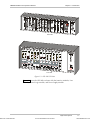
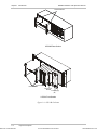
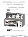
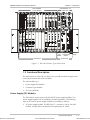
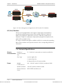
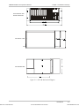
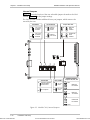
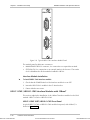
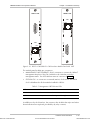
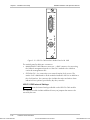
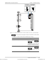
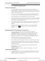
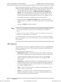
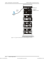
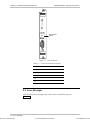
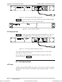
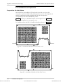
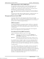
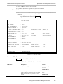
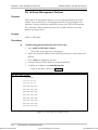
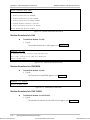
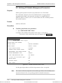
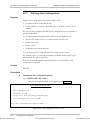
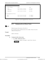
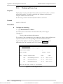
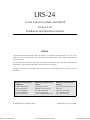
LRS-24 Installation and Operation Manual
Order from: Cutter Networks
Chapter 2 Installation and Setup
PS-LRS
48VDC
PS-LRS/230/115
POWER
POWER
+5V
+5V
-5V
-5V
LRS-24
LRS-24
AC Power Supply Module
DC Power Supply Module
Figure 2-3. PS Module Panels
Table 2-1. PS Modules, Front Panel Indicators
Indicator
POWER
+5V
–5V
Function
Status
At least one of the PS modules installed in LRS-24
is receiving input power and can provide +5V
Lights up (green)
LRS-24 is not receiving power
Off
This PS module is providing a normal +5V output
voltage
Green
+5V is not available in LRS-24
Off
This PS module is providing a normal –5V output
voltage
Green
–5V is not available in LRS-24
Off
Fuses
The PS modules include internal fuses that should not be replaced by the user.
In addition, the AC power supply (PS-LRS/230/115) is protected by an external,
user-replaceable fuse located in the AC power connector of the corresponding
interface module, which protects the input line.
Installation and Setup
Ph:727-398-5252/Fax:727-397-9610
2-7
www.bestdatasource.com