1
Appendix E: High-speed Input and Pulse Output Features
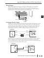
Writing Your Control Program
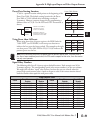
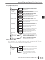
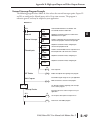
You may recall that the Up-Down counter instruction is standard in the DL05 instruction
set. Refer to the figure below. The mnemonic for the counter is UDC (up-down counter).
The DL05 can have up to 128 counters, labeled CT0 through CT177. The quadrature
counter in the HSIO circuit is accessed in ladder logic by using UDC CT76. It uses counter
registers CT76 and CT77 exclusively when the HSIO mode 20 is active (otherwise, CT76
and CT77 are available for standard counter use). The HSIO counter needs two registers
because it is a double-word counter. It also has three inputs as shown, but they are redefined.
The first input is the enable signal, the middle is a preload (write), and the bottom is the
reset. The enable input must be on before the counter will count. The enable input must be
off during a preload.
Standard Counter Function
UP Count
DOWN Count
Reset Input
UDC
CTxx
HSIO Counter Function
Enable Input
Preload Input
Kxxxxxxxx
Reset Input
UDC
CT76
Kxxxxxxxx
Counts UP and DOWN (from X0, X1)
Counts UP and DOWN
Can use Preload Input to change count
Preload counter by write to value
Reset input may be internal or external
Reset input is internal only
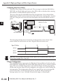
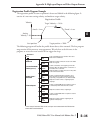
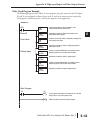
The next figure shows the how the HSIO quadrature counter will appear in a ladder program.
Enable Input
Preload Input
Reset Input
UDC
CT76
Kxxxxxxxx
Preset Range:
1-99999999
When the enable input is energized, the counter will respond to quadrature pulses on X0 and
X1, incrementing or decrementing the counter at CT76 – CT77. The reset input contact
behaves in a logical OR fashion with the physical reset input X2. This means the quadrature
counter can receive a reset from either the contact(s) on the reset rung in the ladder, OR the
external reset X2.
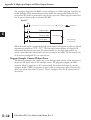
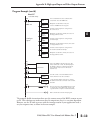
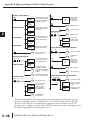
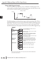
Quadrature Counter w/Preload Program Example
Since presets are not available in quadrature counting, this mode is best suited for simple
counting and measuring. The example program on the following page shows how to
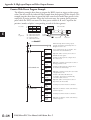
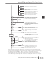
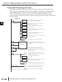
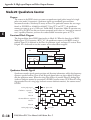
configure the quadrature counter. The program configures the HSIO circuit for Mode 20
operation, so X0 is Phase A and X1 is Phase B clock inputs. Counter w/Preload
DL05 Micro PLC User Manual, 6th Edition, Rev. C
1
2
3
D
E
6
7
8
9
10
11
1
1
14
A
B
C
D
E–21