1
Appendix E: High-speed Input and Pulse Output Features
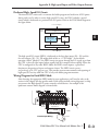
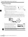
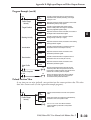
Dedicated High- Speed I/O Circuit
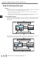
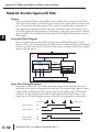
The internal CPU’s main task is to execute the ladder program and read/write all I/O points
during each scan. In order to service high-speed I/O events, the DL05 includes a special
circuit which is dedicated to a portion of the I/O points. Refer to the DL05 block diagram in
the figure below.
6 Discrete Outputs
DL05
PLC
D
Output Circuit
Y0, Y1
Y2 - Y5
High-Speed
I/O Circuit
CPU
X0 - X2
X3 -X7
Input Circuit
8 Discrete Inputs
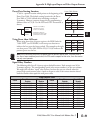
The high-speed I/O circuit (HSIO) is dedicated to the first three inputs (X0 – X2) and the
first two outputs (Y0 – Y1). We might think of this as a “CPU helper”. In the default
operation (called “Mode 60”) the HSIO circuit just passes through the I/O signals to or from
the CPU, so that all eight inputs behave equally and all six outputs behave equally. When the
CPU is configured in any other HSIO Mode, the HSIO circuit imposes a specialized
function on the portion of inputs and outputs shown. The HSIO circuit operates
independently of the CPU program scan. This provides accurate measurement and capturing of
high-speed I/O activity while the CPU is busy with ladder program execution.
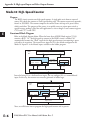
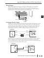
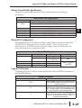
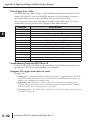
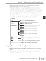
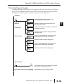
Wiring Diagrams for Each HSIO Mode
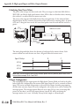
After choosing the appropriate HSIO mode for your application, you’ll need to refer to the
section in this chapter for that specific mode. Each section includes wiring diagram(s) to help
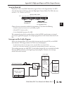
you connect the High-Speed I/O points correctly to field devices. An example of the
quadrature counter mode diagram is shown below.
Signal Common
Phase B
+
Phase A
Encoder Input Wiring
1
2
3
–
12 – 24 VDC
E
6
7
8
9
10
11
1
1
14
A
B
C
D
Encoder
DL05 Micro PLC User Manual, 6th Edition, Rev. C
E–3