1
Appendix E: High-speed Input and Pulse Output Features
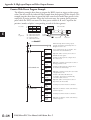
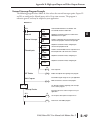
Pulse Catch Program Example
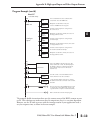
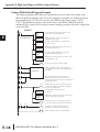
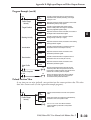
The following program selects Mode 50, then programs the pulse catch code for X0. Inputs
X1 and X2 are configured as filtered inputs with 10 and 30 ms time constants respectively.
The program is otherwise generic, and may be adapted to your application.
DirectSOFT
SP0
Load constant K50 into the accumulator. This
selects Mode 50 as the HSIO mode.
LD
K50
Mode 50
OUT
V7633
Pulse Catch
LD
K5
Filtered Inputs
D
Output this constant to V7633, the location of the
HSIO Mode select register.
Load the constant K5 which is required to configure X0
as the pulse catch input.
OUT
V7634
LD
K1006
OUT
V7635
LD
K3006
OUT
V7636
Output this constant to V7634, configuring the pulse
catch option for X0.
Load the constant K1006 which is required to select
filtered inputs with a 10 ms filter time constant.
Output this constant to V7635, configuring X1.
Load the constant K3006 which is required to select
filtered inputs with a 30 ms filter time constant.
Output this constant to V7636, configuring X2.
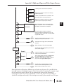
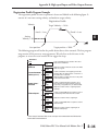
Main Program
X0
Y0
SET
END
Use the pulse catch input to set output Y0 on. This will
work even for a very short pulse on X0.
END coil marks the end of the main program.
DL05 Micro PLC User Manual, 6th Edition, Rev. C
1
2
3
E
6
7
8
9
10
11
1
1
14
A
B
C
D
E–51