1
Appendix E: High-speed Input and Pulse Output Features
1
2
3
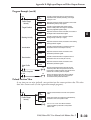
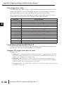
Setup for Mode 20
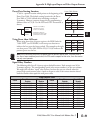
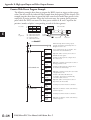
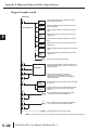
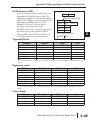
Recall that V7633 is the HSIO Mode Select register. Refer to the diagram below. Use BCD
20 in the lower byte of V7633 to select the High-Speed Counter Mode. The DL05 does not
use bits 8 - 12, 14 and 15 in V7633.
Memory Location V7633
Bits
15
14
13
12
11
10
9
8
7
6
5
4
3
2
1
0
0
0
0
0
0
0
0
0
0
1
0
0
0
0
D
E
6
7
8
9
10
11
1
1
14
A
B
C
D
E–20
0
See page E-5
0
2
0
0
HSIO Mode Setup (BCD)
20 = Quadrature Counter
Choose the most convenient method of programming V7633 from the following:
• Include load and out instructions in your ladder program
• DirectSOFT 5’s memory editor
• Use the Handheld Programmer D2–HPP
We recommend using the first method above so that the HSIO setup becomes an integral
part of your application program. An example program later in this section shows how to do
this.
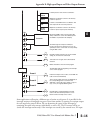
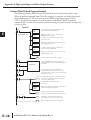
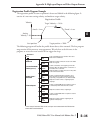
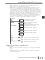
X Input Configuration
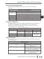
The configurable discrete input options for High-Speed Counter Mode are listed in the table
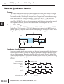
below. Input X0 is dedicated for Phase A, and input X1 is for Phase B. Input X2 is the reset
input to the quadrature counter, but it does not cause an interrupt. The section on Mode 60
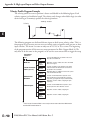
operation at the end of this chapter describes programming the filter time constants.
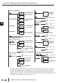
Input
Configuration
Register
Function
Hex Code Required
0002 (default) quadrature,
absolute 0 to 99999999
0012 quadrature, absolute
-8388608 to 8388607
X0
V7634
X1
V7635
X2
V7636
Phase A
1002 quadrature, absolute
0 to 99999999, X4 counting
1012 quadrature, absolute
-8388608 to 8388607,
X4 counting
Phase B
0000
Counter Reset (no interrupt)
0007
Discrete filtered input
1006
DL05 Micro PLC User Manual, 6th Edition, Rev. C