1
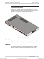
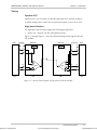
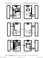
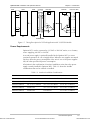
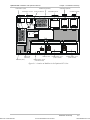
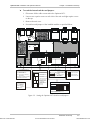
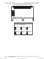
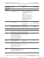
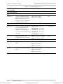
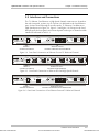
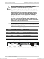
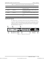
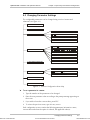
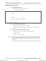
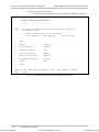
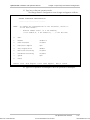
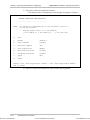
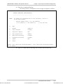
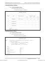
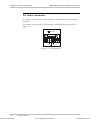
Chapter 3
Operation
3.1 Optimux-XLT1 Controls
This chapter presents information and description of the Optimux-XLT1 front
panel and rear panel controls and the operating procedure for turn ON.
Front Panel Controls
Order from: Cutter Networks
The Optimux-XLT1 front panel provides the LED indications and the connections
to the Ethernet LAN and to the T1 channels as shown in Figure 3-1. Table 3-1lists
the functions of the LEDs, switch and connectors located on the Optimux-XLT1
front panel. Figure 3-2and Figure 3-3 show the High Speed and Fast Ethernet
modules front panel. The index numbers in Table 3-1correspond to the balloon
numbers in Figure 3-1, Figure 3-2and Figure 3-3.
1
4
5
6
10
8
10
B
A
PWR
A
B
SYSTEM
LNK
SYNC A B
FLT
LOSS
TST RST AIS
ETHERNET
OK
OK
ACT
OP-M
2
3
7
9
11
12
11
13
D
C
ETHERNET
ACT
Optimux-XLT1
13
13
ETH/10BT
12
SYNC
LOSS
AIS
SYNC
LOSS
AIS
SYNC
LOSS
AIS
OP-M
4T1/BAL
14
OP-M
14
15
2T1/BAL
15
14
15
Figure 3-1. Optimux-XLT1 Front Panel
1
3
2
4
DCE
V.35
OP-M
4HSx1.5M
16
Figure 3-2. High Speed Module Panels
ETHERNET
100M
ACT
LINK
OP-M
ETH-10/100BT
17
11
18
Figure 3-3. Fast Ethernet Module Panel
Optimux-XLT1 Controls
Ph:727-398-5252/Fax:727-397-9610
3-1
www.bestdatasource.com